Embed Size (px)
Citation preview

SOUTH FORK AND HEART MOUNTAIN FAULTS: EXAMPLES OF CATASTROPHIC, GRAVITY-DRIVEN “OVERTHRUSTS,” NORTHWEST
WYOMING, USA Timothy L. Clarey, PhD, MS, MS, BS, 2878 Oaklawn Park, Saginaw, MI, 48603, KEYWORDS: break-away fault, denudation, detachment, gravity slide, gypsum dehydration, overthrust ABSTRACT Overthrust faults have been a source of debate and discussion in creation literature for many years. Their interpretation demands a better explanation in a Flood context. Two fault systems are examined as analogies for an “overthrust” model. The South Fork Fault System (SFFS) and the Heart Mountain Fault System (HMFS) exhibit folding and faulting consistent with thin-skinned overthrust systems. Both systems moved catastrophically under the influence of gravity. The South Fork Fault system (SFFS, southwest of Cody, Wyoming, exhibits tear faults, tight folds, a triangle zone, and flat-ramp geometries along the leading edge of the system. Transport was southeast, down a gentle slope during early to middle Eocene time (Late Flood), approximately coeval with the Heart Mountain Fault system (HMFS). The SFFS detaches in lower Jurassic strata, rich in gypsum-anhydrite, overlain by about 1250 m of Jurassic through Tertiary sedimentary and volcanic rocks. Movement between 5 km and 10 km to the southeast spread the allochthonous mass over an area exceeding 1400 km2. A break-away fault and an area of tectonic denudation mark the upper northwest part of the system. The exposed denuded surface was buried by additional Eocene-age volcanic rocks soon after slip. Catastrophic rear-loading during emplacement of HMFS may have initiated subsequent movement on the SFFS, with dehydration processes trapping water in a near frictionless anhydrite-water slurry. Rapid development of near-surface folds, as observed in the toe of the SFFS, could only have developed while the sediments were still unlithified.
INTRODUCTION The mechanical difficulty of moving large, coherent sheets of rock great distances down fairly flat slopes has never been fully explained in the geologic literature (Briegel 2001). Lithified sedimentary rock will not fold and behave plastically at surface conditions (Snelling 2009), yet we see the clear geometric results in overthrust belts around the globe. Creationists in the past have been right to criticize secular explanations for overthrusts (Whitcomb and Morris 1961; Lammerts, 1966, 1972; Burdick, 1969, 1974, 1977). Today, however, creationists must accept the results of 100s of drill-hole penetrations and 1000s of kilometers of seismic reflection data, collected since the 1970s, proving the existence of many overthrust faults (Royse et al., 1975; Jones, 1982; Lamerson, 1982; Boyer and Elliott, 1982; Price, 1988; Coogan, 1992). Authors who are critical of the geologic column should no longer use the denial of overthrusts as part of
Proceedings of the Seventh International Conference on Creationism. Pittsburgh, PA: Creation Science Fellowship

their argument. Instead, creationists should embrace these features as an opportunity to explain their unique features within a Flood context. The “rules” of overthrusting, established by the oil industry (Royse et al., 1975; Boyer and Elliot, 1982), suggest consistent movement directions away from uplifted regions. Overthrusts generally get younger in the direction of transport, often folding and further deforming the earlier-emplaced thrust sheets in the process. The apparent “uphill” movement of many overthrusts can be explained as a consequence of later folding by subsequent thrusts or by ramping uphill as the thrusting ceased. Overthrusts, generally, have a basal detachment from which all younger thrusts originate. Prior to development of the modern theory of plate tectonics, most overthrusts were thought of as gravity slides (Hubbert and Rubey, 1959; Eardley, 1963; Roberts, 1968; Mudge, 1970). More recently, and after the advent of plate tectonic theory, overthrusts became thought of as compressional features that are “pushed.” Davis et al. (1983) and Chappel (1978) have pointed out that thrust belts are commonly wedge-shaped and move only when the wedge reaches a critical taper angle. Davis and Reynolds (1996, p. 338) explain that “the critical shear stress required for sliding to occur is equal to the product of the coefficient of sliding friction and the effective stress.” However, published experiments (Davis et al., 1983) were performed with unconsolidated sediments where the basal detachment was “pulled” out from beneath the sediments. Actual “pushing” of rocks from the rear, as commonly believed, results in crushing of the rocks at the point of compression with no detachments and no thrust development (J.R. Baumgardner, pers. comm., 2009). Gravity seems to remain the only viable force to move overthrusts (Snelling, 2009). Uniformitarian geologists are coming back to gravity tectonics to explain some overthrusts. Alvarez (2009), in his discussion of the development of the Alps, believes gravity spreading of uplifted areas drive collapse. “Gravity carries the rising mountains away, thrust sheet by thrust sheet” (Alvarez, 2009, p. 166). High fluid pressures, developing during dewatering reactions, have the ability to create overpressured zones and “float” large thrust sheets down slope (Hubbert and Rubey, 1959; Guth et al. 1982; Clarey, 2012). The formation of supercritical carbon dioxide seems to be an additional method to move carbonate-rich sediments rapidly (Beutner and Gerbi 2005). This paper presents results of a study of the South Fork Fault system (SFFS), and the associated Heart Mountain Fault system (HMFS), as examples of overthrust development within a Flood model. The South Fork Fault system (SFFS) remains the lesser known of two large, enigmatic, gravity-driven fault systems in northwest Wyoming (Figure 1). The more well-known Heart Mountain Fault system (HMFS) has been described, discussed and debated in the geologic literature for over 100 years (Hauge, 1993). Field relations indicate the SFFS and HMFS moved during the early to middle Eocene, and in close proximity to one another. Both faults exhibit transport to the southeast (Pierce, 1986), and both have bedding plane detachments and ramps. Dake (1918) initially described and named the South Fork fault and Pierce further defined and mapped its extent (Pierce, 1941, 1957, 1966, 1970; Pierce and Nelson, 1968, 1969). Bucher (1936) first suggested gravity as a driving mechanism for movement while Blackstone (1985) and Pierce (1986) debated its unusual structural development and mode of emplacement. Clarey

(1990) concluded the South Fork fault is a “fault system” with a single detachment horizon within the Jurassic section, well above the Ordovician detachment horizon for the nearby HMFS. Beutner and Hauge (2009) attempted to link the SFFS and HMFS, but argued for initial slow movement on the SFFS, followed by later rapid movement of the HMFS. Clarey (2012) has resolved the timing relationship between the two fault systems, finding the SFFS to be younger than the HMFS.
GEOLOGIC SETTING The South Fork Fault System Exposures of the South Fork Fault system (SFFS) extend for over 35 km along the South Fork Shoshone River, southwest of Cody, Wyoming, and 30 km northwest up the western flank of Rattlesnake Mountain anticline, a basement-involved Laramide uplift (Figures 1 and 2). Earlier research has demonstrated the presence of tightly-folded sedimentary rocks, tear faults, a triangle zone and other thin-skinned geometries along the leading edge of the allochthonous slide mass, typical of overthrust belts (Figure 3; Clarey, 1990). Transport was to the southeast, down a relatively flat slope (< 5o), in early to middle Eocene time, approximately coeval with the Heart Mountain Fault system (HMFS) (Blackstone, 1985). Well data, seismic data and surface exposures indicate the system detaches in the lower Jurassic Sundance Formation and/or the underlying Jurassic Gypsum Spring Formation. The SFFS consists of nearly 1250 m of Jurassic through Tertiary strata, volcanic deposits, and possibly, several earlier-emplaced HMFS carbonate blocks. Movement between 5 km and 10 km to the southeast spread the allochthonous mass over an area exceeding 1400 km2 (Clarey, 1990, 2008). The SFFS broke into several pieces during transport bounded by tear faults above the detachment in Jurassic rocks, segregating deformation in each segment (Clarey, 1990). The northernmost extent of the SFFS, the break-away fault, was recently identified near the confluence of the Pat O’Hara and Rattlesnake Mountain anticlines (both previously-emplaced, Laramide-age, basement-involved uplifts) (Blackstone, 1985; Clarey, 2008; Figure2). The area comprising the compressional “toe” of the allochthonous slide mass is exposed along the South Fork Shoshone River valley (Figures 2 and 3; Clarey, 1990). This area has been intensely drilled for oil exploration, and contains excellent exposures of tightly-folded strata (Figure 3). The exact extent of the toe is obscured southwest of Hardpan fault (HPF in Figure 2) beneath alluvium and younger Eocene Absaroka volcanic deposits, including the Deer Creek volcanic slide mass described by Malone (1994, 1995, 1996). The northeastern extent of the toe area ends beneath the present Buffalo Bill Reservoir, along the western flank of Rattlesnake Mountain anticline (Figure 2). The Hardpan and Castle faults were described earlier by Clarey (1990) as tear faults in the SFFS that compartmentalized deformation in the toe of the slide. Each of these faults detaches in the Jurassic section as illustrated by published seismic data and well control (Clarey, 1990). These faults also parallel the SFFS transport direction to the southeast (Pierce, 1986). The area northeast of Castle fault (cross-section A’A’; Figure 3) shows a simple ramp thrust that places Jurassic through Eocene rocks upon Upper Cretaceous Cody Shale. Emplacement of the thrust mass either followed a shallow detachment in the upper Cody Shale (Beutner and Hauge, 2009),

or moved along the “former land surface,” similar to Pierce’s concept for emplacement of the HMFS in the Bighorn Basin (Pierce 1957, 1973). Folding of the HMFS is also implied on the northwestern end on A-A’. West of the Castle fault (CTF) and east of the Hardpan fault (cross-sections B-B’ and C-C’; Figure 3) a different style of emplacement is observed. A triangle zone formed in this segment where backthrusting by the Willow fault uplifted the initial southeast-directed thrust mass (Clarey, 1990). Transport along the SFFS placed Jurassic through Eocene rocks on a possible bedding plane detachment in the Cretaceous Cody Shale and cutting across the Eocene Willwood Formation. The area west of the Hardpan fault shows a simple ramp geometry (cross-section D-D’; Figure 3), placing Jurassic through Eocene rocks on an apparent detachment surface in the Upper Cretaceous Frontier Formation. The Cody Shale at this location was eroded away, leaving the Frontier Formation exposed at the surface, prior to SFFS emplacement. Published geologic maps in this area, and adjacent to the Castle fault, show folding and cross-cutting of the Eocene Willwood Formation, suggesting that the Willwood was involved in the SFFS and was transported along with the Mesozoic section beneath (Pierce and Nelson, 1969). All cross-sections across the toe of the SFFS assume southeast-directed transport, parallel to the Castle and Hardpan faults (Figure 2). The sections also illustrate some inconsistencies in transport distance, with cross-sections A-A’, B-B’ and C-C’ exhibiting nearly 10 km of movement while D-D’ indicates a transport distance closer to 5 km. The bedding plane detachment for the SFFS resides in Jurassic strata and extends about 25 km northwest of the South Fork Shoshone River valley, and includes the Sheep and Logan Mountain carbonate blocks, and the area immediately north of the North Fork Shoshone River valley (Figure 2). At least eight well penetrations of the SFFS detachment plane were drilled in the vicinity of the North Fork valley during the late 1960s through the late 1980s. Some duplication of section and dip direction changes were observed in the Jurassic Sundance and/or Gypsum Spring Formations in these wells.
The Heart Mountain Fault System Although this paper deals primarily with the SFFS, a brief introduction to the Heart Mountain Fault system (HMFS) is necessary as the two faults overlap in areal extent and in their near timing of movement. The HMFS (Figure 1) as described and mapped by Pierce (1957, 1966, 1970, 1973) and Pierce and Nelson (1968, 1969), is composed of a bedding plane detachment to the northwest (near the break-away fault), a footwall ramp up to the southeast in the middle part, and a “fault across a former land surface” to the southeast, placing Ordovician and Mississippian-age rocks on top of Eocene Willwood Formation in the northwestern Bighorn Basin (Figure 4). The primary detachment horizon originated within the carbonate rocks of the lower Ordovician section. Carbonate slide blocks nearest the break-away fault, to the northwest, are most coherent and organized, containing Ordovician through Mississippian-age strata, over 400 m thick, which were transported 10s of kilometers southeast during the early to middle Eocene. The amount and extent of the volcanic rocks involved in the sliding are debated.
Pierce’s (1973, 1987a, 1987b; Pierce and Nelson, 1986) model of “tectonic denudation” between blocks has been vigorously debated by Hauge (1985, 1990). Evidence exists for local tectonic transport of volcanic rock between carbonate blocks, but the extent of volcanic rocks deposited after movement took place is unresolved (Pierce et al., 1991). Most of the HMFS slide blocks become smaller and less coherent (disorganized) east of the footwall ramp in the system (Pierce, 1997). Movement of the gravity-driven, HMFS spread carbonate blocks nearly 50 km to the southeast, down a fairly flat slope (<2o), and covered an area greater than 3500 km2 (Beutner and Hauge, 2009). The role of fluids and fluid pressure involvement in the HMFS transport has been discussed since Hubbert and Rubey (1959) and Rubey and Hubbert (1959). Beutner and Gerbi (2005) have more recently made a strong case for catastrophic movement of the HMFS involving supercritical CO2 as the suspending medium, even suggesting that movement rates as high as 150 km/hr may not be unreasonable. Numerical simulations by Goren et al. (2010) have demonstrated a sliding velocity of 112 m/s may have been achieved during movement of the Heart Mountain carbonate block during its emplacement. The exposed HMFS detachment surface at White Mountain shows approximately 3 m of fault breccia in between the hanging wall and the footwall (Figure 5A, 5C). This outcrop exhibits a hanging wall of metamorphosed and folded allochthonous Ordovician Bighorn Dolomite. The autochthonous footwall beneath the HMFS breccia consists of 2 m of unmetamorphosed Bighorn Dolomite above Cambrian Snowy Range Formation. Several clastic dikes up to 1 m wide, originating in the detachment fault breccia and indicative of high fluid pressures, are also visible at the White Mountain site (Figure 5B, 5D). These clastic dikes, or “injectites,” were found to extend 120 m vertically into the hanging wall above the HMFS (Craddock et al., 2012). METHODS Field work was concentrated along the South and North Forks of the Shoshone River valley, supplementing the previous work by the U.S. Geological Survey (Pierce, 1966, 1970, 1997; Pierce and Nelson, 1969, 1969). Additional field work was carried out west of Pat O’Hara Mountain (Figure 2) to examine the SFFS break-away fault. The Heart Mountain Fault System (HMFS) was also studied at White Mountain, part of the bedding plane detachment for the fault system (Pierce, 1957, 1966, 1970, 1973). The location of White Mountain is shown in Figure 4. New structural orientation data were collected to define the extent of the SFFS and fill in areas previously devoid of published information. Rock samples were collected and outcrops of the SFFS and HMFS detachment surfaces were examined. Selected samples were sent to Calgary Rock and Materials Services, Inc. for petrographic thin-section preparation, macro-thin section images and for X-Ray diffraction analysis. Electric well logs and available dipmeter data were examined for orientation and penetrations of the SFFS and HMFS detachment surfaces. Cross sections were constructed using available well data. A detailed geologic map was prepared to illustrate the relationship between the SFFS and the HMFS in the South Fork valley.

RESULTS AND DISCUSSION Outcrop Exposures of the SFFS Detachment Surface in the Toe Area Two outcrops of the SFFS detachment surface were located within the compressional toe of the SFFS. Few exposures exist of the actual detachment surface due to substantial erosion and later Quaternary burial. One outcrop was within the “South Fork Window” along the southwestern end of the SFFS where Jurassic Sundance Formation is emplaced on Cretaceous Frontier Shale (location #1, Figure 2; cross-section D-D’, Figure 3; Figure 6A) (E.C. Beutner and T.A. Hauge, pers. comm., 2007). A second exposure of the SFFS detachment surface was located south of the river where the SFFS emplaced Sundance Formation on top of the exposed Cody Shale (location #2, Figure 2; A-A’ Figure 3; Figure 6B). Although separated by 20 km, both outcrops exhibit about 5 cm of fault gouge between the upper and lower plates. Found within the gouge are abundant selenite gypsum crystals, some exceeding 5 cm in length. There were no slickenlines observed on the detachment surface. Thin-section images of the fault gouge (Figures 6C and 6D) show preferential alignment of gypsum crystals and microfossils subparallel to the detachment plane. Quartz grains are more randomly disbursed within the gouge. An apparent clastic dike was identified about 15 m east of the SFFS window exposure within the upper plate of the SFFS, although the exact connection to the detachment surface was obscured by alluvium. The clastic dike, shown in Figure 7A, averages about 25-30 cm wide and cuts through the Sundance Formation for 3 m, before the exposure becomes lost beneath Quaternary river gravels. Internal laminar flow structures are visible parallel to the sides of the dike. About 10 cm of offset was observed in a sandstone unit cut by the clastic dike, with the east side up, indicating minor movement during or after dike emplacement. A thin-section from the dike material (Figure 7B) indicates a higher proportion of quartz grains are present in the dike samples compared to samples of SFFS gouge (Figure 6C) collected 15 m away. However, the size and angular nature of the quartz grains are similar in both thin-sections. The thin-section from the dike also shows a calcite-filled, vertical fracture running up the left side, paralleling the laminations visible in outcrop. Bulk powder X-ray diffraction (XRD) analysis was performed on two samples of the clastic dike and two samples from the nearby SFFS gouge (Clarey, 2012). Although many of the same minerals were found in all four of the samples, both samples from the dike show higher contents of quartz and orthoclase feldspar and lesser amounts of calcite. Higher amounts of calcite in the SFFS gouge samples may be a consequence of gypsum replacement during exposure and weathering (Figures 6C, 6D) (R. Strom, pers. comm., 2010). Overall, the XRD data show occurrences of many of the same minerals within the clastic dike and the SFFS gouge, but in different proportions. These results are not unexpected as the high fluid flow necessary to produce a clastic dike often results in slightly different textures (Pierce, 1987a, 1987b) and changes in composition between clastic dikes and their source rocks (Winslow, 1983). The

presence of a clastic dike, however, can indicate overpressure-induced hydraulic fracturing (Winslow, 1983; Levi et al., 2006).
New Interpretations within the SFFS Bedding Plane Detachment The construction of cross-section E-E’ (Figure 8) and the northwest extension of C-C’ (Figure 9) utilized two critical well penetrations, the Phillips Buffalo Bill #1 and the General Crude Krueger #1, respectively. Both of these wells drilled through the entire SFFS allochthon, showing virtually no interruption in the stratigraphic section as they passed through the detachment surface. Dipmeter data from the Phillips well showed a consistent 1-5o of southerly dip within the Mesozoic and Paleozoic section, matching available surface exposures, and demonstrating the relatively flat dip of the detachment surface of the SFFS. Only a slight shift in dip azimuth near the detachment plane is evident. The Phillips well (Sec. 26 T 53 N; R 104 W), spudded in allochthonous rocks of the HMFS, drilled through Mississippian, Devonian and Ordovician-age carbonates, and encountered an incomplete section of Cretaceous Cody Shale at 390 m (1235 feet). The well continued through a complete section of Mesozoic-age strata and the Jurassic bedding plane detachment of the SFFS, ending in nearly flat-lying Pennsylvanian-age rocks at total depth of 1985 m (6292 feet). The General Crude well (Sec. 8 T 52 N; R 105 W) spudded in Eocene-age Willwood Formation, encountered a thin Cretaceous Cody Shale section, and continued through a complete stratigraphic section until stopping in the Cambrian Flathead Sandstone at a total depth of 2344 m (7430 feet). Minor repetition along the detachment surface is indicated by stratigraphic thickening of the Jurassic section. Limited repetition of section was observed in the eight well penetrations within the bedding plane segment. These well data demonstrate that the SFFS operated as a bedding plane detachment over a large area, likely within the Jurassic Gypsum Spring Formation or lower Sundance Sandstone, and extending northward to the break-away fault (Figure 2). Based on the frontal imbrications shown on E-E’ (Figure 8), and the lack of a SFFS klippe south of the river, the total transport distance for this section of the SFFS is estimated at less than 5 km. The SFFS Break-away Fault and Denuded Zone Clarey (2008) identified the SFFS break-away fault (Figures 10A and 10B), finding an exposure along the eastern end of an unnamed west-northwest-trending fault mapped by Pierce and Nelson (1968), near the confluence of Rattlesnake Mountain anticline and Pat O’Hara anticline (“#3” on Figure 2). Pierce and Nelson (1968) mapped out the visible extent of this fault west-northwestward for 8 km where the fault was covered beneath younger Absaroka volcanic rocks. The break-away fault turns southeast from exposure #3 and becomes a near bedding plane fault in the Jurassic strata that parallel the basement-involved uplift of Rattlesnake Mountain anticline (Figure 2).
Hanging wall volcanic units against the break-away surface are consistently oriented N 85 W; 25 S and appear to be in depositional contact with the break-away fault plane (Figure 10A). Thin sections of hanging wall rock adjacent to the break-away fault surface show no clear evidence of tectonic deformation (Figures 10C and 10D). The interpretation of a depositional contact for the hanging wall volcanic rocks on to the break-away surface, and not by tectonic emplacement, is reminiscent of the “tectonically denuded” interpretation for the HMFS (Pierce, 1973, 1987a; Pierce and Nelson, 1986). The SFFS break-away is likewise interpreted as having developed as a tectonically-denuded, rift-like opening that was quickly filled with later volcanic rocks (Figure 11). The denuded zone may have been rapidly filled by the subsequent Deer Creek slide mass that is mapped across this area (Malone, 1995, 1996). The lack of carbonate blocks and other HMFS remnants in the denuded zone also supports this interpretation. TIMING OF THE SFF AND HMF SYSTEMS The time of movement of both the SFFS and the HMFS has been dated as early to middle Eocene (Beutner and Hauge, 2009; Clarey, 1990). Cross-cutting relations show that both the SFFS and the HMFS post-date deposition of the Willwood Formation (Pierce and Nelson, 1969; Clarey, 1990) and pre-date the Wapiti Formation (Pierce, 1986). Recently, Clarey (2009, 2012) reported on a critical area of overlap between the two systems constraining the timing relations. He demonstrated with cross-cutting relationships, and subsequent folding of the HMFS surface, that SFFS movement occurred after emplacement of the HMFS. Faulting in both systems probably occurred late in the Flood event (or immediately post-Flood) as deformation affected rocks as old as the Ordovician Period and as young as the Eocene Epoch. SUGGESTED MECHANISM FOR CATASTROPHIC EMPLACEMENT Most authors have concluded that the HMFS was emplaced catastrophically (Bucher, 1933; Pierce, 1973; Voight, 1974; Malone, 1995: Anders et al., 2000; Craddock et al., 2000, 2006; Buetner and Gerbi, 2005; Aharonov and Anders, 2006; Oard, 2006; Anders et al., 2010), with few exception (Sales, 1983; Hauge, 1985, 1990). William Pierce believed that the entire 3500 km2 HMFS was emplaced in a matter of hours (pers. comm., 1990). Beutner and Gerbi (2005) have suggested that the HMFS carbonate blocks moved rapidly, largely undeformed, across this area on a slope of < 2 degrees, and presented evidence of supercritical CO2 as the suspending medium, released by frictional heating and dissociation of carbonate rock along the detachment surface. Beutner and Gerbi (2005) interpreted initiation of movement on the HMFS may have begun by a volcanic or phreatomagmatic explosion, causing total emplacement in only a few minutes. Goren et al. (2010) confirmed high movement rates are plausible for upper plate blocks like Heart Mountain. The SFFS has also been interpreted by most authors as catastrophically emplaced, with the exception of Beutner and Hauge (2009). Pierce (1973) and Blackstone (1985) concluded by
analogy, that if the HMFS moved at cataclysmic rates, then similar rates seem likely for the SFFS. Field evidence to support high fluid pressures along the SFFS detachment includes the presence of abundant gypsum crystals within the fault gouge at both surface exposure locations (Figures 6A, 6B). Most of the gypsum crystals in the fault gouge were probably rehydrated from anhydrite or hemihydrate by recent weathering and exposure. Heard and Rubey (1966) also reported rapid rehydration in their experiments. In addition, the discovery of an apparent clastic dike in the exposed SFFS “window” area supports high fluid pressures within the detachment horizon (Figure 2, #1). “Jigsaw breccia” containing abundant cross-fibre, crack-seal veins along the SFFS detachment surface also supports the interpretation of high fluid pressure in the gypsum/anhydrite of the detachment horizon (Beutner and Hauge, 2009). The breccia experienced up to 40 percent volume gain, possibly reflecting elevated fluid pressures. Hubbert and Rubey (1959) initially advanced the concept that high fluid pressures can be critical in the mechanics of gravity sliding. They suggested that any combination of rapid sedimentary loading, tectonic compressive stresses, break-down of hydrous minerals, and/or melting of the eutectic fraction of a rock may serve to raise fluid pressures to near lithostatic levels and facilitate movement. Although other authors (Davis, 1965; Hsu, 1969; Guth et al., 1982) have been critical of Hubbert and Rubey for not considering the role of cohesive strength and the role of pore pressure, they have concluded that gravity sliding is possible for thrust blocks underlain by a weak layer of gypsum or anhydrite. Heard and Rubey (1964, 1966) demonstrated experimentally that the mechanism that initially raises the fluid pressure within gypsum-anhydrite layers is a dehydration reaction, converting gypsum crystals to a hemihydrates and anhydrite (anhydrite plus water paste). They presented a numerical model that assumed a column of shale above the gypsum layer so that interstitial water could not escape, concluding that gypsum would release 48.5 percent of its volume as water during conversion to anhydrite, thus supporting nearly the full weight of the overburden. This conversion via dehydration would, simultaneously, also produce a rapid drop in aggregate rock strength (Heard and Rubey, 1966). Implicit to their model is the requirement of rapid fault movement in order to maintain the high fluid pressures derived from dehydration reactions. The conditions described by Heard and Rubey (1966) are similar to the conditions present for the SFFS. The upper plate is approximately 1250 m thick, and composed of predominantly Jurassic through Upper Cretaceous shale-rich units, with 20-25 m of gypsum-anhydrite in the Gypsum Spring Formation to serve as the detachment. All that may have been required for movement of the SFFS was for something to “trigger” the action, starting the slide. Late Flood erosion by rapidly receding waters probably removed significant overburden and exposed lower Paleozoic rocks near the HMFS break-away. Similarly-exposed volcanic centers near the break-away likely initiated the explosive movement of the HMFS, as envisioned by Beutner and Gerbi (2005). Rapid loading, by the emplacement of the HMFS, may have been the trigger to initiate movement on the SFFS. Catastrophic emplacement of over 500 m of Ordovician through Mississippian carbonates, and unknown amounts of Absaroka volcanic deposits, on exposed Mesozoic and Tertiary rocks near the SFFS break-away (north of the North

Fork valley) would satisfy the conditions specified by Rubey and Hubbert (1959). Thus, rear loading, combined with the high fluid pressure and loss in cohesive strength from dehydration, overcame static friction and triggered southeast movement. Once movement of the SFFS was initiated by the emplacement of the HMFS, the Jurassic-level SFFS detachment surface would have ramped up section in the toe to the southeast, placing Jurassic though Tertiary rocks on Upper Cretaceous shale units. The forces required to keep the sliding SFFS in motion were lower than the initiation forces as the friction between surfaces in motion (dynamic friction) is lower than static friction (Nur and Burgess, 2008, p. 47). The impermeable Cody Shale likely served to maintain the high fluid pressure, favoring continued thrusting in the toe and the development of the Cody-level detachment surface (cross-sections A-A’, B-B’, C-C’, D-D’, Figure 3). Briegal (2001) has also pointed out that dehydrating gypsum encased in shale is an ideal detachment surface, exhibiting a large fluid source and no place for the fluid to go. Heard and Rubey (1966) further suggested that if the detached plate breaks across and rides over rocks that are relatively impermeable, and not yet fully consolidated, additional high fluid pressure may be generated directly by the loading of the overriding plate. This situation may explain why the SFFS detachment surface also cuts across small segments of Tertiary Willwood Formation in addition to the aforementioned Cody Shale. In summary, the SFFS exhibits all the requirements of a high fluid-pressure system emplaced rapidly: (1) it has a primary detachment surface in the Jurassic strata, rich in gypsum-anhydrite; (2) it has a fluid generation mechanism in the dehydration reaction to anhydrite, which simultaneously raised the internal fluid pressure to near lithostatic and decreased the aggregate strength; (3) it has the rapid emplacement of the HMFS to serve as the “triggering” process, initiating movement down the 3-5o slope by loading on the rear of the system; and (4) it has a toe detachment in the Cody Shale to maintain high fluid pressure during transport along the leading edge of the system. The discovery of a SFFS break-away fault, denuded zone, and detachment surface (analogous to the HMFS) further supports a model of catastrophic emplacement. The tight fold geometries observed in the “toe” area of the SFFS create another interpretation dilemma. Traditional, uniformitarian explanations demand slow development of folded sediments under great confining pressures. The folds in the toe of the SFFS, if developed rapidly, do not satisfy these conditions. They were not buried deeply and under sufficient confining pressure, nor were they developed slow enough to form the geometries that are observed. An alternative explanation, that they formed rapidly while the sediments were still unlithified, seems to better satisfy the documented conditions. CONCLUSIONS The SFFS is composed of coherent Mesozoic and limited Cenozoic-age sedimentary rocks and volcanic rocks. The timing and consistent structural geometries observed within the SFFS and the HMFS imply a connection. Field relations indicate transport on the SFFS and the HMFS during the early to middle Eocene (late or post-Flood). Both fault systems exhibit a consistent transport direction to the southeast, have bedding plane detachments, and have ramps placing older sediments on Eocene-age units. These similarities make it necessary to examine both faults, simultaneously, into one comprehensive interpretation, without exclusion.

The model presented here involves a three-stage history of development for the SFFS (Figure 12). All of the movement is assumed to have taken place in rapid succession during the early to middle Eocene, following a rapid erosional event by withdrawing Flood waters. Although some volcanic rocks were involved in movement, none are shown on the diagrams to emphasize the movement of the HMFS carbonate blocks. Stage 1 Late or post-Flood volcanic activity caused the recently exposed rocks comprising the HMFS to separate along a break-away fault and catastrophically slide southeast, transporting large carbonate blocks such as Logan Mountain to the southeast (Figure 12, Stage 1; Figure 13A). Rattlesnake Mountain apparently served as a buttress during emplacement the HMFS, splitting off the southern edge of the HMFS, and transporting it in a more southerly direction. Stage 2 Rapid loading by the carbonate blocks and volcanic rocks of the HMFS served as a kinetic “trigger” for the SFFS as it rifted along its incipient break-away fault. This rear loading, combined with the high fluid pressure and loss in cohesive strength from dehydration reactions in the Jurassic gypsum-rich layers, allowed transport to the southeast, possibly at the rate of a superfault (> 0.1 m/s) (Spray, 1997). Movement on the SFFS caused “piggy-back” style transport of several of the carbonate blocks of the HMFS, transporting Logan and Sheep Mountain farther southeast (Figures 12, 13B). The SFFS moved predominantly southeast, approximately parallel to the major tear faults. The end of Stage 2 left the tectonically denuded zones largely exposed for both the SFFS and the HMFS. Stage 3 Deposition of additional Absaroka volcanic units quickly buried both denuded surfaces, preserving the planar SFFS break-away fault and the HMFS break-away fault (Pierce, 1987b). Much of the SFFS and HMFS were covered with younger Absaroka volcanic rocks (the Wapiti Formation of Pierce and Nelson, 1968, 1969) and the Deer Creek slide mass (Malone, 1994, 1995, 1996). Completion of Stage 3, and the end of Absaroka volcanism, left the northwestern Wyoming region exposed to further withdrawal of the remaining Flood waters and weathering and erosion, resulting in the topography that is observed today (Figure 12). Final Conclusions All data suggest overthrust faults like the SFFS and HMFS moved rapidly. Some fault breccia and/or fault gouge was identified along the surface contact of both fault systems. The breccia/gouge thicknesses varied from several meters to just a few millimeters. In addition, clastic dikes were observed in the hanging wall of both fault systems, further supporting the catastrophic interpretation. Unlithified sediments are essential to the development of overthrust faults in order to explain the tightly-folded geometries that are observed in the toe areas. These conditions must have occurred late in the Flood after most of the sediments were deposited, but

while they were still uncemented. Rapid deposition during the Flood, combined with compaction and dewatering of clay-rich sediments and gypsum layers, created overpressured zones along impermeable boundaries. In the case of the SFFS and HMFS, rapidly receding Flood waters likely exposed the Paleozoic and Mesozoic section and the volcanic centers, allowing volcanic activity to initiate movement on the HMFS (Beutner and Gerbi 2005). Initiation of the SFFS followed in close succession as tectonic loading by the emplaced HMFS caused slippage in the underlying Jurassic section (Clarey, 2012). Likewise, late Flood uplift probably initiated sliding along overpressured horizons along many mountain fronts all over the world, causing thrusts to propagate into the so-called “thrust belts.” Once thrusting was initiated, tectonic loading likely caused subsequent thrusts to slide out from underneath, creating the “piggy-back” pattern of younger thrusts in the direction of transport. Secular explanations of overthrusts (Price, 1988), using slow movement and maintenance of overpressured horizons over great distances, still cannot resolve the glaring mechanical paradox. However, the Flood model of overthrusting, involving rapid downhill movement of unlithified sediments, provides both a cause and a mechanism for the development of large thrust sheets and the resulting tightly-folded geometries in the toe areas. Uniformitarian geologists rely on high confining pressures (deep burial), high temperatures, or vast amounts of time to increase the strength and ductility of rock, allowing folding to take place (Davis and Reynolds, 1996). The catastrophic development of tight folding in the SFFS effectively eliminates the factors of time and a slow strain rate. The shallow depth of the detachment (less than 1250 m) eliminates high confining pressures and high temperatures, leaving the resultant geometries baffling for uniformitarian explanation. However, folds in coherent thrust sheets have been shown to develop in unlithified sediments in laboratory settings (Davis et al., 1983). Therefore, the SFFS is interpreted to have moved and deformed while the sediments were still unlithified. This could only have occurred if the sediments were laid down rapidly and recently, either post-Flood or late in the Flood. Furthermore, rapid sedimentation, loading and compaction during the Flood provides the most likely scenario for overpressured horizons to develop and serve as detachment horizons for overthrusts. ACKNOWLEDGMENTS Brad Pretzer is thanked for his help as field assistant and endless help with drafting. I thank Ed Stratman and Stan Strike, for their guidance in the field. I am indebted to Ray Strom and Calgary Rock and Materials Services, Inc., for their help in preparing thin-sections and XRD analyses, and John Whitmore of Cedarville University, for assistance with imaging the thin-sections. I am indebted to Tom Hauge and Ed Beutner for their assistance with outcrop locations and thoughtful discussions. Also, I thank Curt Bales of the TE Ranch, Aldo Largura, Mary Anne Dingus, Dan Stewart, and Joel Gough, who gracefully allowed me access to their various properties. I also acknowledge Tina Kaczmarek for her acquisition of various documents and papers, allowing me to complete this research. Finally, I wish to thank Henry Morris III, Steve Austin, Charles McCombs and John Morris for their continued support of the project. This research was partially funded by National Creation Science Foundation Grant 2009-001 and ICR.

REFERENCES Aharonov, E., and Anders, M.H. (2006). Hot water: a solution to the Heart Mountain detachment
problem? Geology, 34(3), 165-168. Anders, M.H., Aharonov, E., and Walsh, J.J. (2000). Stratified granular media beneath large
slide blocks: implications for mode of emplacement. Geology, 28(11), 971-974. Anders, M.H., Fouke, B.W., Zerkle, A.W., Tavarnelli, E., Alvarez, W., and Harlow, G.E. (2010).
The role of calcining and basal fluidization in the long runout of carbonate slides: an example from the Heart Mountain slide block, Wyoming and Montana, U.S.A. The Journal of Geology, 118(6), 577-599.
Alvarez, W. (2009). The mountains of Saint Francis-discovering the geologic events that shaped
our Earth. New York: Norton. Beutner, E.C., and Gerb, G.P. (2005). Catastrophic emplacement of the Heart Mountain block
slide, Wyoming and Montana, USA. Geological Society of America Bulletin, 117(5/6), 724-735.
Beutner, E.C., and Hauge, T.A. (2009). Heart Mountain and South Fork fault systems:
architecture and evolution of the collapse of an Eocene volcanic system, northwest Wyoming. Rocky Mountain Geology, 44(2), 147-164.
Blackstone, D.L., Jr. (1985). South Fork detachment fault, Park County, Wyoming: geometry-
extent-source. Contributions to Geology, 23, 47-62. Boyer, S.E., and Elliott, D. (1982). Thrust systems. American Association of Petroleum
Geologists Bulletin, 66, 1196-1230. Briegel, U. (2001). Rock mechanics and the paradox of overthrusting tectonics. In U. Briegel,
and W. Xiao (Eds.), Paradoxes in geology (pp. 231-244). Amsterdam, Netherlands: Elsevier, B.V.
Bucher, W.H. (1933). Volcanic explosions and overthrusts. American Geophysical Union, 14th
Annual Meeting Transactions, 238-242. Bucher, W.H. (1947). Heart Mountain problem. Wyoming Geological Association and
Yellowstone-Bighorn Research Association Guidebook to Field Conference in the Bighorn Basin, University of Wyoming, 189-197.
Burdick, C.L. (1969). The Empire Mountains – a thrust fault? Creation Research Society
Quarterly, 6(1), 49-54. Burdick, C.L. (1974) Additional notes concerning the Lewis thrust-fault: Creation Research
Society Quarterly, 11(1), 56-60.

Burdick, C.L. (1977). Heart Mountain revisited. Creation Research Society Quarterly, 13(4),
207-210. Chapple, W.M. (1978). Mechanics of thin-skinned fold-and-thrust belts. Geological Society of
America Bulletin, 89, 1189-1198. Clarey, T.L. (1990). Thin-skinned shortening geometries of the South Fork fault: Bighorn basin,
Park County, Wyoming. The Mountain Geologist, 27, 19-26. Clarey, T.L. (2008). The break-away point of the South Fork superfault: a catastrophic gravity
slide, Wyoming, USA. Geological Society of America Abstracts with Programs, 40(6), 312-313.
Clarey, T.L. (2009). Timing relations between the South Fork and Heart Mountain fault systems
with implications for emplacement, Wyoming, USA. Geological Society of America Abstracts with Programs, 41(7), 570.
Clarey, T.L. (2012). South Fork fault as a gravity slide: its break-away, timing, and
emplacement, northwestern Wyoming, U.S.A. Rocky Mountain Geology, 47(1), 55-79.. Coogan, J.C. (1992). Structural evolution of piggyback basins in the Wyoming-Idaho-Utah thrust
belt. In P.K. Link, M.A. Kuntz, and L.B. Platt (Eds.), Regional Geology of Eastern Idaho and Western Wyoming (pp. 55-81). Geological Society of America Memoir 179.
Craddock, J.P., Geary, J., and Malone, D.H. (2012). Vertical injectites of detachment carbonate
ultracataclasite at White Mountain, Heart Mountain detachment, Wyoming. Geology, 40(5), 463-466.
Craddock, J.P., Malone, D.H., Magloughlin, J., Cook, A.L., Rieser, M.E., and Doyle, J.R.
(2009). Dynamics of the emplacement of the Heart Mountain allochthon at White Mountain: constraints from calcite twinning strains, anisotropy of magnetic susceptibility, and thermodynamic calculations. Geological Society of America Bulletin, 121(5/6), 919-938.
Craddock, J.P., Nielson, K.J., and Malone, D.H. (2000). Calcite-twinning strain constraints on
the emplacement rate and kinematic pattern of the upper plate of the Heart Mountain Detachment. Journal of Structural Geology, 22(7), 983-991.
Dake, C.L. (1918). The Hart Mountain overthrust and associated structures in Park County,
Wyoming. Journal of Geology, 26, 45-55. Davis, D.M., Suppe, J., and Dahlen, F.A. (1983). Mechanics of fold-and-thrust belts and
accretionary wedges. Journal of Geophysical Research, 88, 1153-1172.

Davis, G.A. (1965). Role of fluid pressure in mechanics of overthrust faulting: Discussion Geological Society of America Bulletin, 76, 463-468.
Davis, G.H., and Reynolds, S.J. (1996). Structural Geology of Rocks and Regions, 2nd, Ed. New
York: John Wiley and Sons, Inc. Eardley, A.J. (1963). Relation of uplifts to thrusts in Rocky Mountains. In Backbone of the
Americas. American Association of Petroleum Geologists Memoir 2, 209-219. Goren, L., Aharonov, E., and Anders, M.H. (2010). The long runout of the Heart Mountain
landslide: heating, pressurization, and carbonate decomposition. Journal of Geophysical Research, 115, B10210.
Guth, P.L., Hodges, K.V., and Willemin, J.H. (1982). Limitations on the role of pore pressure in
gravity gliding. Geological Society of America Bulletin, 93(7), 606-612. Hauge, T.A. (1985). Gravity-spreading origin of the Heart Mountain allochthon, northwestern
Wyoming. Geological Society of America Bulletin, 96, 1440-1456. Hauge, T.A. (1990). Kinematic model of a continuous Heart Mountain allochthon: Geological
Society of America Bulletin, 102, 1174-1188. Hauge, T.A. (1993). The Heart Mountain detachment, northwestern Wyoming: 100 years of
controversy. In A.W. Snoke, J.R. Steidtmann, and S.M. Roberts (Eds.), Geology of Wyoming (pp. 530-571). Geological Survey of Wyoming Memoir 5.
Heard, H.C., and Rubey, W.W. (1964). Possible tectonic significance of transformation of
gypsum to anhydrite plus water. The Geological Society of America, Abstracts for 1963. Geological Society of America Special Paper 76, 77-78.
Heard, H.C., and Rubey, W.W. (1966). Tectonic implications of gypsum dehydration:
Geological Society of America Bulletin, 77, 741-760. Hsu, K.J. (1969). Role of cohesive strength in the mechanics of overthrust faulting and of
landsliding. Geological Society of America Bulletin, 80, 927-952. Hubbert, M.K., and Rubey, W.W. (1959). Role of fluid pressure in mechanics of overthrust
faulting. I. Mechanics of fluid-filled porous solids and its application to overthrust faulting. Geological Society of America Bulletin, 70, 115-166.
Jones, P.B. (1982). Oil and gas beneath east-dipping underthrust faults in the Alberta Foothills.
In R.B. Powers (Ed.), Geologic Studies of the Cordilleran Thrust Belt, Volume 1 (pp. 61-74). Denver, Colorado: Rocky Mountain Association of Geologists.
Lamerson, P.R. (1982). The Fossil Basin and its relationship to the Absaroka thrust system,
Wyoming and Utah. In R.B. Powers (Ed.), Geologic Studies of the Cordilleran Thrust

Belt, Volume 1 (pp. 279-340). Denver, Colorado: Rocky Mountain Association of Geologists.
Lammerts, W.E. (1966). Overthrust faults of Glacier National Park. Creation Research Society
Quarterly, 3(1), 61-62. Lammerts, W.E. (1966). The Glarus overthrust. Creation Research Society Quarterly, 8(4), 251-
255. Levi, T., Weinberger, R., Aifa, Y., Eyal, Y., and Marco, S. (2006). Earthquake-induced clastic
dikes detected by anisotropy of magnetic susceptibility. Geology, 34(2), 69-72. Malone, D.H. (1994). A debris-avalanche origin for Eocene volcanic rocks overlying the Heart
Mountain detachment, northwest Wyoming [Ph.D. thesis] Madison, Wisconsin: University of Wisconsin, 294 p.
Malone, D.H. (1995). Very large debris-avalanche deposit within the Eocene volcanic succession
of the northeastern Absaroka Range, Wyoming. Geology, 23(7), 661-664. Malone, D.H. (1996). Revised stratigraphy of Eocene volcanic rocks in the lower North and
South Fork Shoshone River valleys, Wyoming. Wyoming Geological Association Annual Field Conference Guidebook, 47, 109-138.
Mudge, M.R. (1970). Origin of the Disturbed belt in northwestern Montana. Geological Society
of America Bulletin, 81, 377-392. Nur, A., and Burgess, D. (2008). Apocalypse-Earthquakes, Archaeology, and the Wrath of God.
Princeton, New Jersey: Princeton University Press. Oard, M. (2006). The Heart Mountain catastrophic slide. Journal of Creation 20(3), 3-4. Pierce, W.G. (1941). Heart Mountain and South Fork thrusts, Park County, Wyoming. American
Association of Petroleum Geologists Bulletin, 25, 2021-2046. Pierce, W.G. (1957). Heart Mountain and South Fork detachment thrusts of Wyoming: American
Association of Petroleum Geologists Bulletin, 41, 591-626. Pierce, W.G. (1960). The “break-away” point of the Heart Mountain detachment fault in
northwestern Wyoming. In Short papers in the geological sciences. U.S. Geological Survey Professional Paper 400-B, B236-B237.
Pierce, W.G. (1966). Geologic map of the Cody Quadrangle, Park County, Wyoming: USGS
Quadrangle Map GQ-542, 1:62,500. Pierce, W.G. (1970). Geologic map of the Devil’s Tooth Quadrangle, Park County, Wyoming:
USGS Quadrangle Map GQ-817, 1:62,500.

Pierce, W.G. (1973). Principal features of the Heart Mountain fault and the mechanism problem.
In K.A. DeJong, and R. Scholten (Eds.), Gravity and Tectonics (pp. 457-471). New York: John Wiley and Sons.
Pierce, W.G. (1980). The Heart Mountain break-away fault, northwestern Wyoming. Geological
Society of America Bulletin, Part 1, 91, 272-281. Pierce, W.G. (1986). The South Fork detachment fault, Park County, Wyoming: Discussion and
reply. Contributions to Geology, 24, 77-90. Pierce, W.G. (1987a). The case for tectonic denudation by the Heart Mountain fault - a response.
Geological Society of America Bulletin, 99, 552-568. Pierce, W.G. (1987b). Heart Mountain detachment and clastic dikes of fault breccia, and Heart
Mountain break-away fault, Wyoming and Montana. In Geological Society of America Centennial Field Guide – Rocky Mountain Section, 2, 147-154.
Pierce, W.G. (1997). Geologic map of the Cody 1o x 2o Quadrangle, northwestern Wyoming.
USGS Miscellaneous Investigation Series I-2500, 1:250,000. Pierce, W.G., and Nelson, W.H. (1968). Geologic map of the Pat O’Hara Mountain Quadrangle,
Park County, Wyoming. USGS Quadrangle Map GQ-755, 1:62,500. Pierce, W.G., and Nelson, W.H. (1969). Geologic map of the Wapiti Quadrangle, Park County,
Wyoming. USGS Quadrangle Map GQ-778, 1:62,500. Pierce, W.G., and Nelson, W.H. (1986). Some features indicating tectonic denudation by the
Heart Mountain fault. Montana Geological Society and Yellowstone-Bighorn Research Association Guidebook to Field Conference in the Bighorn Basin, 155-164.
Pierce, W.G., Nelson, W.H., Tokarski, A.K., and Piekarska, E. (1991). Heart Mountain
Wyoming, detachment lineations: are they in microbreccia or in volcanic tuff? Geological Society of America Bulletin, 103, 1133-1145.
Price. R.A. (1988). The mechanical paradox of large overthrusts. Geological Society of America
Bulletin, 100, 1898-1908. Roberts, R.J. (1968). Tectonic framework of the Great Basin. In A coast to coast tectonic study
of the United States. University of Missouri Research Journal 1, 101-119. Royse, F., Jr., Warner, M.A., and Reese, D.L. (1975). Thrust belt structural geometry and related
stratigraphic problems, Wyoming-Idaho-Northern Utah. Rocky Mountain Association of Geologists 1975 Symposium, 41-54.

Rubey, W.W., and Hubbert, M.K. (1959). Role of fluid pressure in mechanics of overthrust faulting. II. Overthrust belt in geosynclinals area of western Wyoming in light of fluid-pressure hypothesis. Geological Society of America Bulletin, 70, 167-205.
Sales, J.H. (1983). Heart Mountain-blocks in a giant volcanic rock glacier. In W.W. Boberg
(Ed.), Geology of the Bighorn Basin (pp. 117-167). Wyoming Geological Association Guidebook 34th Annual Field Conference.
Snelling, A.A. (2009). Earth’s catastrophic past: geology, creation and the Flood. Dallas,
Texas: Institute for Creation Research. Spray, J.G. (1997). Superfaults. Geology, 25(7), 579-582. Voight, B. (1974). Architecture and mechanics of the Heart Mountain and South Fork rockslides.
In B. Voight, and M.A. Voight (Eds.), Rock Mechanics: The American Northwest: 3rd Congress International Society of Rock Mechanics Expedition Guidebook (pp. 26-36), Special Publication, Experiment Station, College of Earth and Mineral Sciences, The Pennsylvania State University.
Whitcomb, J.C., and Morris, H.M. (1961). The Genesis Flood the Biblical record and its
scientific implications. Grand Rapids, Michigan: Baker Book House. Winslow, M.A. (1983). Clastic dike swarms and the structural evolution of the foreland fold and
thrust belt of the southern Andes. Geological Society of America Bulletin, 94(9), 1073-1080.

FIGURES
Figure 1. Index map showing the regional geologic features associated with the South Fork Fault system (SFFS), after Pierce and Nelson (1968), Pierce and Nelson (1969), Clarey (1990) and Pierce (1997). Darker, cross-hatched pattern represents allochthonous Heart Mountain Fault system (HMFS) carbonate blocks. Gray-shaded pattern represents Absaroka Supergroup volcanic deposits, both pre- and post-SFFS, undivided. BMF-Black Mountain fault; CFF-Clarks Fork fault; CM-Carter Mountain; CZ-Cenozoic rocks, undivided; HM-Heart Mountain; LM-Logan Mountain; MP-McCullough Peaks; MZ-Mesozoic rocks, undivided; NFSR-North Fork Shoshone River; PC-Precambrian rocks, undivided; POM-Pat O’Hara Mountain; PZ-Paleozoic rocks, undivided; RM-Rattlesnake Mountain; SFSR-South Fork Shoshone River; SM-Sheep Mountain; SR-Shoshone River.

Figure 2. Simplified geologic map of the SFFS (Pierce and Nelson, 1968; Pierce and Nelson, 1969; Clarey, 1990 and Pierce, 1997). Darker, cross-hatched pattern represents allochthonous HMFS carbonate blocks. Gray-shaded pattern represents Absaroka Supergroup volcanic deposits, both pre- and post-SFFS, undivided. White areas represent Precambrian-Cenozoic rocks, undivided. Cross-section locations indicated. CTF-Castle Tear fault; CZ-Cenozoic rocks, undivided; HPF-Hardpan fault; HM- Heart Mountain; LM-Logan Mountain; MZ-Mesozoic rocks, undivided; NFSR-North Fork Shoshone River; POM-Pat O’Hara Mountain; PZ-Paleozoic rocks, undivided; RF-Rimrock fault; RM-Rattlesnake Mountain; SFB-South Fork break-away fault; SFW-South Fork Window; SL-“slumped” limestone blocks; SLS-“squeezed” limestone remnants discussed in text; SMT-Sheep Mountain tear fault; SFSR-South Fork Shoshone River; SM-Sheep Mountain; WF-Willow fault. Numbers 1, 2 and 3 are locations of SFFS fault surface exposures discussed in text.

Figure 3. Cross-sections A-A’, B-B’, C-C’, D-D’ modified from Clarey (1990). Locations shown on Figure 2. Sections drawn parallel to interpreted direction of transport. All sections are 1:1.

Figure 4. Map of the Heart Mountain Fault System (HMFS), modified from Pierce (1987b). The location of White Mountain is shown.

Figure 5. Photographs of the HMFS detachment surface and clastic dike (injectite) at White Mountain (Figure 4) and respective macro-thin-section images. (A) HMFS breccia at White Mountain with a thickness of about 3 m. The hanging wall, composed of metamorphosed Ordovician Bighorn Dolomite (Ob), is out of view. The footwall consists of 2 m of unmetamorphosed, basal Bighorn Dolomite (Ob) on top of Cambrian Snowy Range Formation (out of view). (B) Clastic dike (injectite) in hanging wall of HMFS at White Mountain. Dike is over 1 m wide at base and is injected upwards into marbleized Bighorn Dolomite (Ob). (C) Macro-thin-section image of HMFS breccia or carbonate ultracataclasite (Craddock, et al., 2012); feldspar and double carbonate stained. (D) Macro-thin-section image of clastic dike carbonate ultracataclasite; feldspar and double carbonate stained. The green minerals are volcanic fragments. Vertical flow texture within injectite is visible.

Figure 6. Photographs of SFFS detachment surface exposures and respective thin-sections. (A) SFFS window exposure showing allochthonous Jurassic Sundance Formation (Js) on Cretaceous Frontier Formation (Kf), labeled #1 on Figure 2. Arrow indicates SFFS detachment surface. (B) Carter Ranch exposure showing allochthonous Jurassic Sundance Formation (Js) on Cretaceous Cody Shale (Ks), labeled #2 on Figure 2. Arrow indicates SFFS detachment surface. (C) Photomicrograph of fault gouge from SFFS window exposure, normal polarity, feldspar and double carbonate stained. Note long, bladed gypsum crystals that have been replaced partially by calcite. (D) Photomicrograph of fault gouge from Carter Ranch exposure, normal polarity, feldspar and double carbonate stained. Note long, bladed gypsum crystals that are partially replaced by calcite.

Figure 7. Photographs of clastic dike at SFFS window exposure within allochthonous Jurassic Sundance Formation (Js), labeled #1 on Figure 2. (A) Outcrop shows vertical flow texture within the dike and the slight offset on either side of the dike. (B) Photomicrograph of clastic dike, normal polarity, feldspar and double carbonate stained. Jurassic Sundance Formation (Js) is on both sides of the dike. Arrow points to calcite-filled fracture on left side.

Figure 8. Cross-section E-E’. Location shown on Figure 2. Split version of 1:1 cross-section shown with the north part above and the south part below. Section drawn parallel to interpreted direction of transport. Kc-Cretaceous Cody Shale; Kf-Kt-Cretaceous Frontier through Cretaceous Thermopolis Formations; Kd-Jm-Cretaceous Dakota through Jurassic Morrison Formations; Js-Jgs-Jurassic Sundance through Jurassic Gypsum Spring Formations; Tc-Triassic Chugwater and Dinwoody Formations; Pp-Pa-Permian Phosphoria through Pennsylvanian Amsden Formations; Mm-Ob; Mississippian Madison through Ordovician Bighorn Formations.
Figure 9. Cross-section Extended C-C’. Location shown on Figure 2. This cross-section extends the original C-C’ to the northwest and the SFFS break-away fault. Split version of 1:1 cross-section shown with the north part above and the south part below. Section drawn parallel to interpreted direction of transport. Rock units are the same as in Figure 8 with the addition of Twl, Eocene Willwood Formation.
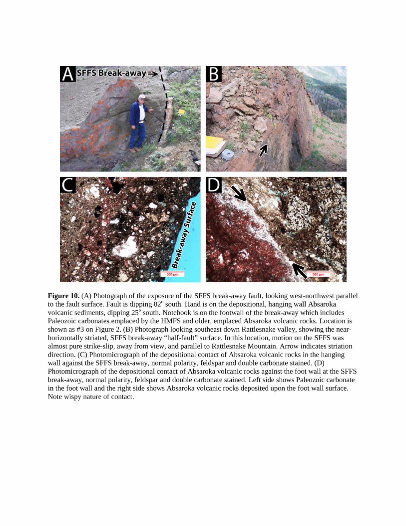
Figure 10. (A) Photograph of the exposure of the SFFS break-away fault, looking west-northwest parallel to the fault surface. Fault is dipping 82o south. Hand is on the depositional, hanging wall Absaroka volcanic sediments, dipping 25o south. Notebook is on the footwall of the break-away which includes Paleozoic carbonates emplaced by the HMFS and older, emplaced Absaroka volcanic rocks. Location is shown as #3 on Figure 2. (B) Photograph looking southeast down Rattlesnake valley, showing the near-horizontally striated, SFFS break-away “half-fault” surface. In this location, motion on the SFFS was almost pure strike-slip, away from view, and parallel to Rattlesnake Mountain. Arrow indicates striation direction. (C) Photomicrograph of the depositional contact of Absaroka volcanic rocks in the hanging wall against the SFFS break-away, normal polarity, feldspar and double carbonate stained. (D) Photomicrograph of the depositional contact of Absaroka volcanic rocks against the foot wall at the SFFS break-away, normal polarity, feldspar and double carbonate stained. Left side shows Paleozoic carbonate in the foot wall and the right side shows Absaroka volcanic rocks deposited upon the foot wall surface. Note wispy nature of contact.

Figure 11. Simplified map of the SFFS break-away fault and estimated denuded area. Darker, cross-hatched pattern represents allochthonous Heart Mountain fault carbonate blocks. Gray-shaded pattern represents Absaroka Supergroup volcanic deposits. CZ-Cenozoic rocks, undivided; MZ-Mesozoic rocks, undivided; PZ-Paleozoic rocks, undivided.

Figure 12. Three-stage model for development of the SFFS using the northwest end of cross-section E-E’, including Logan Mountain. Stage 1: Immediately after emplacement of the HMFS and associated Paleozoic carbonate blocks and selected Absaroka volcanic rocks (not shown). HMFS moved across a fairly flat, erosional surface developed in the early to middle Eocene. Stage 2: Immediately after movement on the SFFS, creating the SFFS break-away fault and denuded surface. Note Logan Mountain was moved, “piggy-back style,” an additional 5 km southeast as a result of the SFFS. Stage 3: Present day configuration showing later Absaroka volcanic rocks filling the denuded zone and covering much of the SFFS break-away fault. The Phillips well drilled through both the HMFS and the SFFS detachment surfaces.

Figure 13. (A) Reconstructed geologic map of the HMFS immediately after emplacement and before movement on the SFFS, after Pierce and Nelson (1968), Pierce and Nelson (1969), Clarey (1990) and Pierce (1997). Logan Mountain and Sheep Mountain carbonate blocks (of the HMFS) are drawn side-by-side in this reconstruction. Darker, cross-hatched pattern represents allochthonous HMFS carbonate blocks. Gray-shaded pattern represents Absaroka Supergroup volcanic deposits. CZ-Cenozoic rocks, undivided; HM-Heart Mountain; LM-Logan Mountain; MP-McCullough Peaks; MZ-Mesozoic rocks, undivided; PC-Precambrian rocks, undivided; PZ-Paleozoic rocks, undivided; RM-Rattlesnake Mountain; SM-Sheep Mountain. (B) Simplified geologic map of the extent of the SFFS, showing overlap with the earlier emplaced HMFS. The interpreted SFFS denuded area is also shown. Differential movement along the Sheep Mountain tear fault during SFFS transport caused separation of Sheep Mountain and Logan Mountain, moving 10 km and 5 km, respectively.