Embed Size (px)
Citation preview
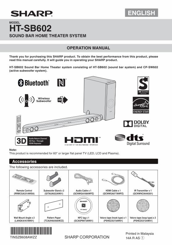
ENGLISHMODEL
HT-SB602SOUND BAR HOME THEATER SYSTEM
OPERATION MANUAL
Thank you for purchasing this SHARP product. To obtain the best performance from this product, please read this manual carefully. It will guide you in operating your SHARP product.
Note:This product is recommended for 60" or larger fl at panel TV (LED, LCD and Plasma).
HT-SB602 Sound Bar Home Theater system consisting of HT-SB602 (sound bar system) and CP-SW602 (active subwoofer system).
AccessoriesThe following accessories are included.
Remote Control(RRMCGA331AWSA)
Subwoofer Stand x 2(GITAUA022AW01)
Audio Cable x 1(QCNWGA108AWPZ)
HDMI Cable x 1(QCNWGA077AWPZ)
IR Transmitter x 1(QCNWNC064AS01)
Wall Mount Angle x 2(LANGKA167AW01)
Pattern Paper(TCAUHA036AWZZ)
NFC tag x 1(GCASP8973AW01)
Velcro tape (hook type) x 1(PSHEZA373AW01)
Velcro tape (loop type) x 2(PSHEZA372AW01)
TINSZB608AWZZPrinted in Malaysia14A R AS 1
E-1
Special Notes
CAUTION: TO REDUCE THE RISK OF ELECTRICSHOCK, DO NOT REMOVE COVER (OR BACK).NO USER-SERVICEABLE PARTS INSIDE. REFERSERVICING TO QUALIFIED SERVICE PERSONNEL.
Explanation of Graphical Symbols:
The lightning flash with arrowhead symbol,within an equilateral triangle, is intended toalert the user to the presence ofuninsulated “dangerous voltage” within theproduct’s enclosure that may be ofsufficient magnitude to constitute a risk ofelectric shock to persons.
The exclamation point within an equilateraltriangle is intended to alert the user to thepresence of important operating andmaintenance (servicing) instructions in theliterature accompanying the appliance.
WARNING: TO REDUCE THE RISK OF FIRE ORELECTRIC SHOCK, DO NOT EXPOSE THIS APPLIANCE TO RAIN OR MOISTURE.
FOR YOUR RECORDSFor your assistance in reporting this unit in case of lossor theft, please record below the model number andserial number which are located on the rear of the unit.Please retain this information.
Model number ........................................................Serial number ........................................................Date of purchase ........................................................Place of purchase ........................................................
NOTEThis equipment has been tested and found to comply with the limits for a Class B digital device, pursuant to Part 15 of the FCC Rules. These limits are designed to provide reasonable protection against harmful interference in a residential installation. This equipment generates, uses, and can radiate radio frequency energy and, if not installed and used in accordance with the instructions, may cause harmful interference to radio communications. However, there is no guarantee that interference will not occur in a particular installation. If this equipment does cause harmful interference to radio or television reception, which can be determined by turning the equipment off and on, the user is encouraged to try to correct the interference by one or more of the following measures:
Reorient or relocate the receiving antenna. Increase the separation between the equipment and
receiver. Connect the equipment into an outlet on a circuit
different from that to which the receiver is connected. Consult the dealer or an experienced radio/TV
technician for help.
WARNINGFCC Regulations state that any unauthorized changes ormodifi cations to this equipment not expressly approved by the manufacturer could void the user’s authority to operate this equipment.
FCC Radiation Exposure StatementThis device complies with the limits for a Class B digital device, pursuant to Part 15 of the FCC Rules. It must not be co-located or operating in conjunction with any other antenna or transmitter.Operation is subject to the following two conditions:1. This device may not cause harmful interference, and 2. This device must accept any interference received,
including interference that may cause undesired operation.
This equipment should be installed and operated with a minimum distance of 20 cm between the radiator and person’s body (excluding extremities: hands, wrists, feet and ankles.)
IC Radiation Exposure Statement (For users in Canada)The radio communications device incorporated into this apparatus meets all requirements of the Industry Canada Radio Frequency Exposure Rules RSS-210. This Class B digital apparatus complies with the Canadian ICES-003 Class B specifi cations.Operation is subject to the following two conditions:1. This device may not cause harmful interference, and2. This device must accept any interference received,
including interference that may cause undesired operation.
This equipment should be installed and operated with a minimum distance of 20 cm between the radiator and person’s body (excluding extremities: hands, wrists, feet and ankles.)
Note to CATV system installer:This reminder is provided to call the CATV system installer’s attention to Article 820 of the National Electrical Code that provides guidelines for proper grounding and, in particular, specifi es that the cable ground shall be connected to the grounding system of the building, as close to the point of cable entry as practical.
ENERGY STAR® Program Information
Products that have earnedthe ENERGY STAR® aredesigned to protect theenvironment throughsuperior energy efficiency.
ENERGY STAR® is a U.S. registered mark.
Manufactured under license under U.S. Patent Nos: 5,956,674; 5,974,380; 6,487,535 & other U.S. and worldwide patents issued & pending. DTS, the Symbol, & DTS and the Symbol together are registered trademarks & DTS Digital Surround and the DTS logos are trademarks of DTS, Inc. Product includes software.© DTS, Inc. All Rights Reserved.
Manufactured under license from Dolby Laboratories. Dolby and the double-D symbol are trademarks of Dolby Laboratories.
HDMI, the HDMI Logo, and High-Defi nition Multimedia Interface are trademarks or registered trademarks of HDMI Licensing LLC in the United States and other countries.
E-2
Important Safety Instructions
Electricity is used to perform many useful functions, but itcan also cause personal injuries and property damage ifimproperly handled. This product has been engineeredand manufactured with the highest priority on safety.However, improper use can result in electric shock and/orfire. In order to prevent potential danger, please observethe following instructions when installing, operating andcleaning the product. To ensure your safety and prolongthe service life of this product, please read the followingprecautions carefully before use.1) Read these instructions.2) Keep these instructions.3) Heed all warnings.4) Follow all instructions.5) Do not use this apparatus near water.6) Clean only with dry cloth.7) Do not block any ventilation openings. Install in
accordance with the manufacturer’s instructions.8) Do not install near any heat sources such as radiators,
heat registers, stoves, or other apparatus (includingAmplifiers) that produce heat.
9) Do not defeat the safety purpose of the polarized orgrounding-type plug. A polarized plug has two bladeswith one wider than the other. A grounding type plughas two blades and a third grounding prong. The wideblade or the third prong are provided for your safety. Ifthe provided plug does not fit into your outlet, consultan electrician for replacement of the obsolete outlet.
10) Protect the power cord from being walked on orpinched particularly at plugs, conveniencereceptacles, and the point where they exit from theapparatus.
11) Only use attachments/accessories specified by themanufacturer.
13) Unplug this apparatus during lightning storms or whenunused for long periods of time.
14) Refer all servicing to qualified service personnel.Servicing is required when the apparatus has beendamaged in any way, such as power-supply cord orplug is damaged, liquid has been spilled or objectshave fallen into the apparatus, the apparatus hasbeen exposed to rain or moisture, does not operatenormally, or has been dropped.
Additional Safety Information15) Power Sources - This product should be operated
only from the type of power source indicated on themarking label. If you are not sure of the type of powersupply to your home, consult your product dealer orlocal power company. For product intended to operatefrom battery power, or other sources, refer to theoperating instructions.
16) Overloading - Do not overload wall outlets, extensioncords, or integral convenience receptacles as this canresult in a risk of fire or electric shock.
17) Object and Liquid Entry - Never push objects of any kindinto this product through openings as they may touchdangerous voltage points or short-out parts that couldresult in a fire or electric shock. To prevent fire or shock hazard, do not expose thisappliance to dripping or splashing. No objects filled withliquids, such as vases, shall be placed on the apparatus.
18) Damage Requiring Service - Unplug this product fromthe wall outlet and refer servicing to qualified servicepersonnel under the following conditions:a) When the AC cord or plug is damaged,b) If liquid has been spilled, or objects have fallen
into the product,c) If the product has been exposed to rain or water,d) If the product does not operate normally by
following the operating instructions. Adjust onlythose controls that are covered by the operatinginstructions as an improper adjustment of othercontrols may result in damage and will oftenrequire extensive work by a qualified technician torestore the product to its normal operation,
e) If the product has been dropped or damaged inany way, and
f) When the product exhibits a distinct change inperformance - this indicates a need for service.
19) Replacement Parts - When replacement parts arerequired, be sure the service technician has usedreplacement parts specified by the manufacturer orhave the same characteristics as the original part.Unauthorized substitutions may result in fire, electricshock, or other hazards.
20) Safety Check - Upon completion of any service orrepairs to this product, ask the service technician toperform safety checks to determine that the product isin proper operating condition.
21) Wall or ceiling mounting - When mounting the producton a wall or ceiling, be sure to install the productaccording to the method recommended by themanufacturer.
22) Power Lines - An outside antenna system should notbe located in the vicinity of overhead power lines orother electric light or power circuits, or where it can fallinto such power lines or circuits. When installing anoutside antenna system, extreme care should betaken to keep from touching such power lines orcircuits as contact with them might be fatal.
23) Protective Attachment Plug - The product is equippedwith an attachment plug having overload protection.This is a safety feature. See Instruction Manual forreplacement or resetting of protective device. Ifreplacement of the plug is required, be sure theservice technician has used a replacement plugspecified by the manufacturer that has the sameoverload protection as the original plug.
24) Stand - Do not place the product on an unstable cart,stand, tripod or table. Placing the product on anunstable base can cause the product to fall, resultingin serious personal injuries as well as damage to theproduct. Use only a cart, stand, tripod, bracket or tablerecommended by the manufacturer or sold with theproduct. When mounting the product on a wall, besure to follow the manufacturer’s instructions. Useonly the mounting hardware recommended by themanufacturer.
12) Use only with the cart, stand, tripod, bracket, or table specified by the manufacturer, or sold with the apparatus. When a cart is used, use caution when moving the cart/apparatus combination to avoid injury from tip-over.
E-3
For U.S. customer only
CONSUMER LIMITED WARRANTYSHARP ELECTRONICS CORPORATION warrants to the first consumer purchaser that this Sharp brand product (the "Product"), when ship in its original container, will be free from defective workmanship and materials, and agrees that it will,at its option, either repair the defect or replace the defective Product or part thereof with a new or remanufactured equivalentat no charge to the purchaser for parts or labor for the period(s) set forth below.
This warranty does not apply to any appearance items of the Product nor to the additional excluded item(s) set forth below nor to any Product the exterior of which has been damaged or defaced, which has been subjected to improper voltage or other misuse, abnormal service or handling, or which has been altered or modified in design or construction.
In order to enforce the rights under this limited warranty, the purchaser should follow the steps set forth below and provide proof of purchase to the servicer.
The limited warranty described herein is in addition to whatever implied warranties may be granted to purchasers by law. ALL IMPLIED WARRANTIES INCLUDING THE WARRANTIES OF MERCHANTABILITY AND FITNESS FOR USE ARE LIMITED TO THE PERIOD(S) FROM THE DATE OF PURCHASE SET FORTH BELOW. Some states do not allow limitations on how long an implied warranty lasts, so the above limitation may not apply to you.
Neither the sales personnel of the seller nor any other person is authorized to make any warranties other than those described herein, or to extend the duration of any warranties beyond the time period described herein on behalf of Sharp.
The warranties described herein shall be the sole and exclusive warranties granted by Sharp and shall be the sole and exclusive remedy available to the purchaser. Correction of defects, in the manner and for the period of time described herein, shall constitute complete fulfillment of all liabilities and responsibilities of Sharp to the purchaser with respect to the Product, and shall constitute full satisfaction of all claims, whether based on contract, negligence, strict liability or otherwise.In no event shall Sharp be liable, or in any way responsible, for any damages or defects in the Product which were caused by repairs or attempted repairs performed by anyone other than an authorized servicer. Nor shall Sharp be liable or in any way responsible for any incidental or consequential economic or property damage. Some states do not allow the exclusion of incidental or consequential damages, so the above exclusion may not apply to you.
THIS LIMITED WARRANTY IS VALID ONLY IN THE FIFTY(50) UNITED STATES, THE DISTRICT OF COLUMBIA ANDPUERTO RICO.
Model Specific Section
Your Product Model Number & Description:
Warranty Period for this Product:
Additional Item(s) Excluded from Warranty Coverage (if any):
Where to Obtain Service:
What to do to Obtain Service:
HT-SB602 Sound Bar Home Theater System
(Be sure to have this information available when you need service for your Product.)
One (1) year parts and labor from the date of purchase.
Non-functional accessories, supplies, and consumable items.
At a Sharp Authorized Servicer located in the United States. To find a location of the nearest Sharp Authorized Servicer, call Sharp toll free at 1-800-BE-SHARP.
Ship prepaid or carry in your Product to a Sharp Authorized Servicer. Be sure to have Proof of Purchase available. If you ship the Product, be sure it is insured and packaged securely.
TO OBTAIN SUPPLY, ACCESSORY OR PRODUCT INFORMATION, CALL 1-800-BE-SHARP
SHARP ELECTRONICS CORPORATIONSharp Plaza, Mahwah, New Jersey 07495-1163
Special NotesThe Bluetooth® word mark and logos are registered trademarks owned by Bluetooth SIG, Inc. and any use of such marks by SHARP is under license. Other trademarks and trade names are those of their respective owners.
The N Mark is a trademark or registered trademark of NFC Forum, Inc. in the United States and in other countries.
E-4
Precautions
General
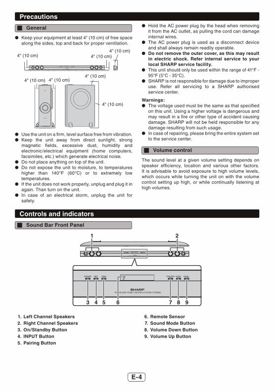
Keep your equipment at least 4" (10 cm) of free space along the sides, top and back for proper ventilation.
4" (10 cm)4" (10 cm) 4" (10 cm)
4" (10 cm)4" (10 cm) 4" (10 cm)
4" (10 cm)
Use the unit on a fi rm, level surface free from vibration. Keep the unit away from direct sunlight, strong
magnetic fi elds, excessive dust, humidity and electronic/electrical equipment (home computers, facsimiles, etc.) which generate electrical noise.
Do not place anything on top of the unit. Do not expose the unit to moisture, to temperatures
higher than 140°F (60°C) or to extremely low temperatures.
If the unit does not work properly, unplug and plug it in again. Than turn on the unit.
In case of an electrical storm, unplug the unit for safety.
Hold the AC power plug by the head when removing it from the AC outlet, as pulling the cord can damage internal wires.
The AC power plug is used as a disconnect device and shall always remain readily operable.
Do not remove the outer cover, as this may result in electric shock. Refer internal service to your local SHARP service facility.
This unit should only be used within the range of 41°F - 95°F (5°C - 35°C).
SHARP is not responsible for damage due to improper use. Refer all servicing to a SHARP authorised service center.
Warnings: The voltage used must be the same as that specifi ed
on this unit. Using a higher voltage is dangerous and may result in a fi re or other type of accident causing damage. SHARP will not be held responsible for any damage resulting from such usage.
In case of repairing, please bring the entire system set to the service center.
Volume control
The sound level at a given volume setting depends on speaker effi ciency, location and various other factors. It is advisable to avoid exposure to high volume levels, which occurs while turning the unit on with the volume control setting up high, or while continually listening at high volumes.
Controls and indicators
Sound Bar Front Panel
1
3 4 5 76 8 9
2
1. Left Channel Speakers2. Right Channel Speakers3. On/Standby Button4. INPUT Button5. Pairing Button
6. Remote Sensor7. Sound Mode Button8. Volume Down Button9. Volume Up Button
E-5
Controls and indicators (continued)
Display
DIGITAL
DIGITAL
1 2
3
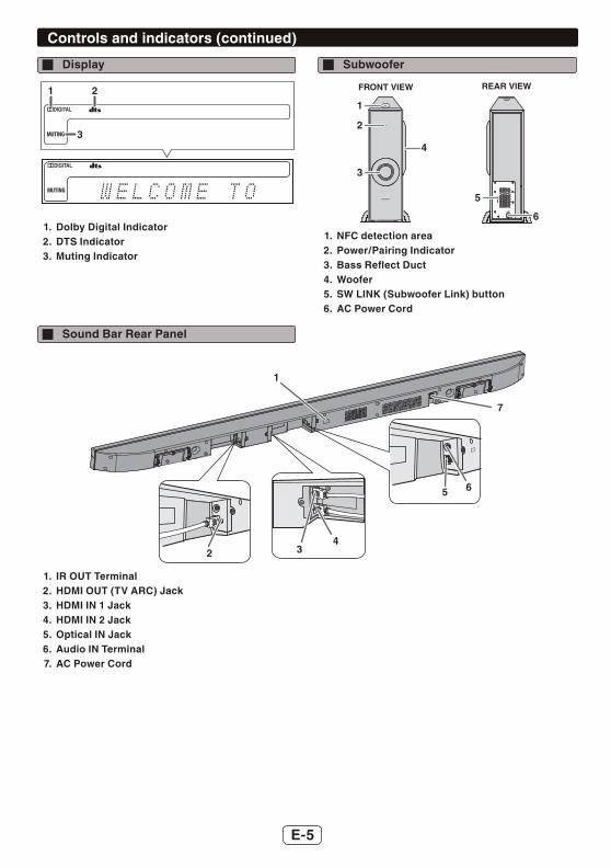
1. Dolby Digital Indicator2. DTS Indicator3. Muting Indicator
Subwoofer
5
3
4
2
6
FRONT VIEW REAR VIEW
1
1. NFC detection area2. Power/Pairing Indicator3. Bass Refl ect Duct4. Woofer5. SW LINK (Subwoofer Link) button6. AC Power Cord
Sound Bar Rear Panel
7
65
432
1
1. IR OUT Terminal2. HDMI OUT (TV ARC) Jack3. HDMI IN 1 Jack4. HDMI IN 2 Jack5. Optical IN Jack6. Audio IN Terminal7. AC Power Cord
E-6
Controls and indicators (continued)
1
2
4
5
7
8
9
12
16
17
18
19
13
15
14
3
6
1110
20
22
23
24
26
27
29
30
33
34
35
31
32
21
25
28
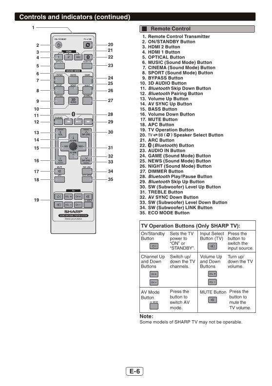
Remote Control1. Remote Control Transmitter2. ON/STANDBY Button3. HDMI 2 Button4. HDMI 1 Button5. OPTICAL Button6. MUSIC (Sound Mode) Button7. CINEMA (Sound Mode) Button8. SPORT (Sound Mode) Button9. BYPASS Button
10. 3D AUDIO Button11. Bluetooth Skip Down Button12. Bluetooth Pairing Button13. Volume Up Button14. AV SYNC Up Button15. BASS Button16. Volume Down Button17. MUTE Button18. APC Button19. TV Operation Button20. ( ) Speaker Select Button21. ARC Button22. (Bluetooth) Button23. AUDIO IN Button24. GAME (Sound Mode) Button25. NEWS (Sound Mode) Button26. NIGHT (Sound Mode) Button27. DIMMER Button28. Bluetooth Play/Pause Button29. Bluetooth Skip Up Button30. SW (Subwoofer) Level Up Button31. TREBLE Button32. AV SYNC Down Button33. SW (Subwoofer) Level Down Button34. SW (Subwoofer) LINK Button35. ECO MODE Button
TV Operation Buttons (Only SHARP TV):On/Standby
AV Mode Button
MUTE Button
ButtonSets the TV
Press the button to switch AVmode.
Press the button to mute the TV volume.
power to “ON” or “STANDBY”.
Input Select Button (TV)
Press the button to switch the input source.
Channel Up and Down Buttons
Switch up/down the TV channels.
Volume Up and Down Buttons
Turn up/down the TV volume.
Note:Some models of SHARP TV may not be operable.
E-7
Sound bar preparation
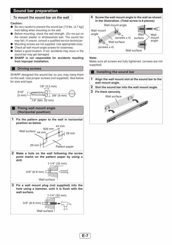
To mount the sound bar on the wall
Caution: Be very careful to prevent the sound bar [7.9 lbs. (3.7 kg)]
from falling when mounting on the wall. Before mounting, check the wall strength. (Do not put on
the veneer plaster or whitewashed wall. The sound bar may fall.) If unsure, consult a qualifi ed service technician.
Mounting screws are not supplied. Use appropriate ones. Check all wall mount angle screws for looseness. Select a good location. If not, accidents may occur or the
sound bar may get damaged. SHARP is not responsible for accidents resulting
from improper installation.
Driving screws
SHARP designed the sound bar so you may hang them on the wall. Use proper screws (not supplied). See below for size and type.
1/8" (3.2 mm)
3/8" (9 mm)
7/8" (Min. 22 mm)
3/16"(5 mm)
Fixing wall mount angle(Horizontal position)
1 Fix the pattern paper to the wall in horizontal position as below.
Wall surface
Pattern paper
44 mm
44 mm
29 mm
29 mm
926 mm
2 Make a hole on the wall following the screw point marks on the pattern paper by using a drill.
Wall surface
1-1/4" (32 mm)
3/8" (8-9 mm)
3 Fix a wall mount plug (not supplied) into the hole using a hammer, until it is fl ush with the wall surface.
Wall surface
1-1/4" (32 mm)
3/8" (8-9 mm)
4 Screw the wall mount angle to the wall as shown in the illustration. (Total screw is 8 pieces)
Wall mount angle
Wall mount angle Wall
mount angle
(screws x 4)
(screws x 4)
Wall surface
Wall surface
Wall surface
Note:Make sure all screws are fully tightened. (screws are not supplied)
Installing the sound bar
1 Align the wall mount slot at the sound bar to the wall mount angle.
2 Slot the sound bar into the wall mount angle.
3 Fix them securely.
Wall surface
E-8
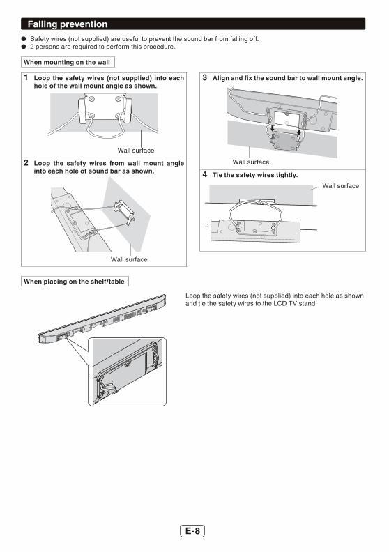
Falling prevention Safety wires (not supplied) are useful to prevent the sound bar from falling off. 2 persons are required to perform this procedure.
When mounting on the wall
1 Loop the safety wires (not supplied) into each hole of the wall mount angle as shown.
Wall surface
2 Loop the safety wires from wall mount angle into each hole of sound bar as shown.
Wall surface
3 Align and fi x the sound bar to wall mount angle.
Wall surface
4 Tie the safety wires tightly.
Wall surface
When placing on the shelf/table
Loop the safety wires (not supplied) into each hole as shownand tie the safety wires to the LCD TV stand.

E-9
Placing the systemInstallation image:
TV
VCR DVD player Subwoofer
Sound Bar
Place the system as shown.
Remove the protective fi lm covering the sound bar andsubwoofer before turn on the system.
Notes: The front panel of the sound bar is not removable. The transmission distance of the wireless signal
between the subwoofer and sound bar is about 32 feet (10m), but may vary depending on your operating environment. If a steel-concrete or metallic wall is between the subwoofer and the sound bar, the system may not operate at all, because the wireless signal cannot penetrate metal.
Caution: Do not change the installation direction when the
sound bar is turned on. Do not stand or sit on the sound bar and subwoofer as
you may be injured. Do not allow any objects to fall into or to be placed in
the bass refl ex duct.
Placing the stand
Place the stand as shown.
Stand
System connections
Make sure to unplug the AC power cord before making any connections.
Subwoofer
Sound Bar
AC outletAC 120 V ~ 60 Hz AC outlet
AC 120 V ~ 60 Hz
CAUTION:TO PREVENT ELECTRIC SHOCK, MATCH WIDE BLADE OF PLUG TO WIDE SLOT, FULLY INSERT.
E-10
System connections (continued)
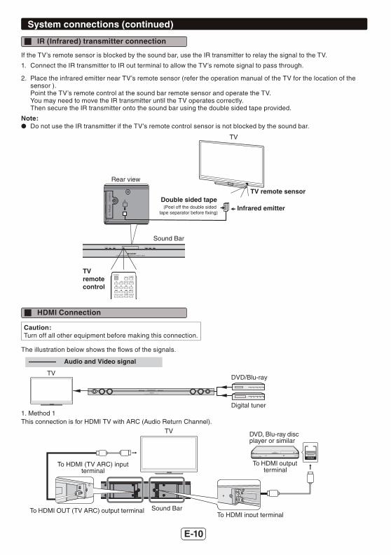
IR (Infrared) transmitter connection
If the TV’s remote sensor is blocked by the sound bar, use the IR transmitter to relay the signal to the TV.
1. Connect the IR transmitter to IR out terminal to allow the TV’s remote signal to pass through.
2. Place the infrared emitter near TV’s remote sensor (refer the operation manual of the TV for the location of the sensor ).Point the TV’s remote control at the sound bar remote sensor and operate the TV.You may need to move the IR transmitter until the TV operates correctly.Then secure the IR transmitter onto the sound bar using the double sided tape provided.
Note: Do not use the IR transmitter if the TV’s remote control sensor is not blocked by the sound bar.
Infrared emitterDouble sided tape
TV remote sensor
TVremotecontrol
TV
Sound Bar
(Peel off the double sided tape separator before fixing)
Rear view
HDMI Connection
Caution:Turn off all other equipment before making this connection.
The illustration below shows the fl ows of the signals.
1. Method 1This connection is for HDMI TV with ARC (Audio Return Channel).
Digital tuner
DVD/Blu-rayTV
Audio and Video signal
TV DVD, Blu-ray disc player or similar
To HDMI output terminal
To HDMI (TV ARC) input terminal
To HDMI OUT (TV ARC) output terminalTo HDMI input terminal
Sound Bar
E-11
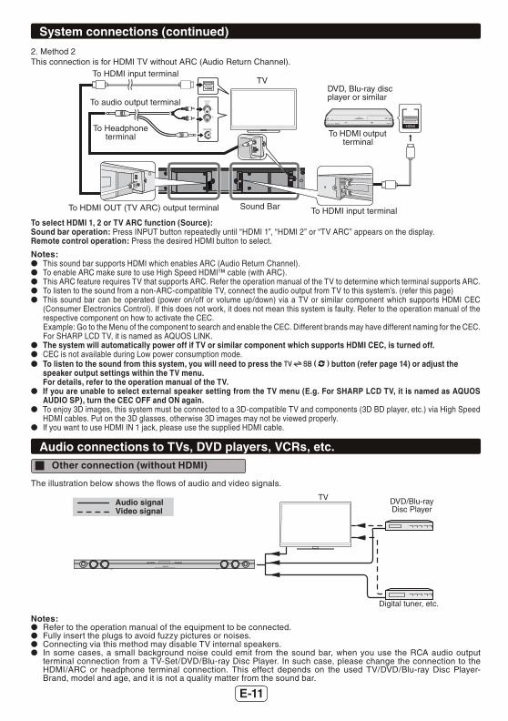
System connections (continued)
2. Method 2This connection is for HDMI TV without ARC (Audio Return Channel).
TVDVD, Blu-ray disc player or similar
To HDMI output terminal
To HDMI input terminal
To HDMI input terminalTo HDMI OUT (TV ARC) output terminal Sound Bar
To audio output terminal
To Headphone terminal
To select HDMI 1, 2 or TV ARC function (Source):Sound bar operation: Press INPUT button repeatedly until “HDMI 1”, “HDMI 2” or “TV ARC” appears on the display.Remote control operation: Press the desired HDMI button to select.
Notes: This sound bar supports HDMI which enables ARC (Audio Return Channel). To enable ARC make sure to use High Speed HDMI™ cable (with ARC). This ARC feature requires TV that supports ARC. Refer the operation manual of the TV to determine which terminal supports ARC. To listen to the sound from a non-ARC-compatible TV, connect the audio output from TV to this system’s. (refer this page) This sound bar can be operated (power on/off or volume up/down) via a TV or similar component which supports HDMI CEC
(Consumer Electronics Control). If this does not work, it does not mean this system is faulty. Refer to the operation manual of the respective component on how to activate the CEC.Example: Go to the Menu of the component to search and enable the CEC. Different brands may have different naming for the CEC. For SHARP LCD TV, it is named as AQUOS LINK.
The system will automatically power off if TV or similar component which supports HDMI CEC, is turned off. CEC is not available during Low power consumption mode. To listen to the sound from this system, you will need to press the ( ) button (refer page 14) or adjust the
speaker output settings within the TV menu.For details, refer to the operation manual of the TV.
If you are unable to select external speaker setting from the TV menu (E.g. For SHARP LCD TV, it is named as AQUOS AUDIO SP), turn the CEC OFF and ON again.
To enjoy 3D images, this system must be connected to a 3D-compatible TV and components (3D BD player, etc.) via High Speed HDMI cables. Put on the 3D glasses, otherwise 3D images may not be viewed properly.
If you want to use HDMI IN 1 jack, please use the supplied HDMI cable.
Audio connections to TVs, DVD players, VCRs, etc. Other connection (without HDMI)
The illustration below shows the fl ows of audio and video signals.
DVD/Blu-ray Disc Player
Digital tuner, etc.
TVAudio signalVideo signal
Notes: Refer to the operation manual of the equipment to be connected. Fully insert the plugs to avoid fuzzy pictures or noises. Connecting via this method may disable TV internal speakers. In some cases, a small background noise could emit from the sound bar, when you use the RCA audio output
terminal connection from a TV-Set/DVD/Blu-ray Disc Player. In such case, please change the connection to the HDMI/ARC or headphone terminal connection. This effect depends on the used TV/DVD/Blu-ray Disc Player-Brand, model and age, and it is not a quality matter from the sound bar.

E-12
Audio connections to TVs, DVD players, VCRs, etc. (continued)
Connecting a TV, or DVD player, etc.
Connect to the TV using an optical digital cable or an audio cable.
TV
Audio cable (commercially
available)
To AUDIO IN input terminals
Optical digital audio cable
(commercially available)
Sound Bar
Audio signal
To optical digital audio
output terminal
To audio output terminals
To HEADPHONE
terminal
To OPTICAL IN (optical)
input terminal
or
Blu-Ray/DVD player/Digital
Tuner
To select OPTICAL function:Sound bar operation: Press INPUT button repeatedly until “OPTICAL” appears on the display.Remote control operation: Press the “OPTICAL” button.
To select AUDIO IN function:Sound bar operation:Press INPUT button repeatedly until “AUDIO IN” appears on the display.Remote control operation: Press the “AUDIO IN” button.
Remote control
Battery installation
Use 2 “AAA” size battery (UM-4, R03, HP-16 or similar).Batteries are not included.
1 Open the battery cover.2 Insert the batteries according to the direction
indicated in the battery compartment.When inserting or removing the battery, push them toward the battery terminals.
3 Close the battery cover.
Caution: Remove the battery if the sound bar will not be used
for a long period of time. This will prevent potential damage due to battery leakage.
Do not use rechargeable battery (nickel-cadmium battery, etc.).
Installing the battery incorrectly may cause the sound bar to malfunction.
Batteries (battery pack or battery installed) shall not be exposed to excessive heat such as sunshine, fi re or the like.
Notes concerning use: Replace the battery if the operating distance is reduced
or if the operation becomes erratic. Periodically clean the transmitter on the remote control
and the sensor on the sound bar with a soft cloth. Exposing the sensor on the sound bar to strong light
may interfere with operation. Change the lighting or the direction of the sound bar.
Keep the remote control away from moisture, heat, shock, and vibrations.
E-13
Remote control (continued)
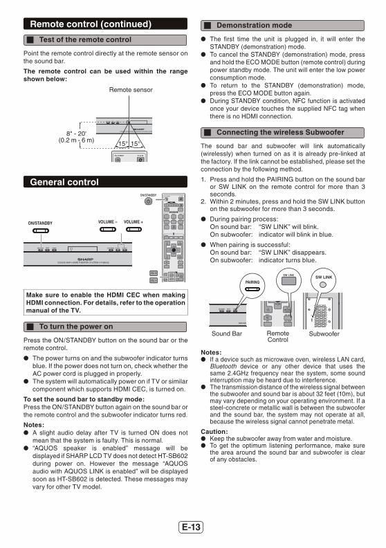
Test of the remote control
Point the remote control directly at the remote sensor on the sound bar.
The remote control can be used within the range shown below:
Remote sensor
8" - 20'(0.2 m - 6 m) 15°15°
General control
Make sure to enable the HDMI CEC when making HDMI connection. For details, refer to the operation manual of the TV.
To turn the power on
Press the ON/STANDBY button on the sound bar or the remote control.
The power turns on and the subwoofer indicator turns blue. If the power does not turn on, check whether the AC power cord is plugged in properly.
The system will automatically power on if TV or similar component which supports HDMI CEC, is turned on.
To set the sound bar to standby mode:Press the ON/STANDBY button again on the sound bar or the remote control and the subwoofer indicator turns red.
Notes: A slight audio delay after TV is turned ON does not
mean that the system is faulty. This is normal. “AQUOS speaker is enabled” message will be
displayed if SHARP LCD TV does not detect HT-SB602 during power on. However the message “AQUOS audio with AQUOS LINK is enabled” will be displayed soon as HT-SB602 is detected. These messages may vary for other TV model.
Demonstration mode
The fi rst time the unit is plugged in, it will enter the STANDBY (demonstration) mode.
To cancel the STANDBY (demonstration) mode, press and hold the ECO MODE button (remote control) during power standby mode. The unit will enter the low power consumption mode.
To return to the STANDBY (demonstration) mode, press the ECO MODE button again.
During STANDBY condition, NFC function is activated once your device touches the supplied NFC tag when there is no HDMI connection.
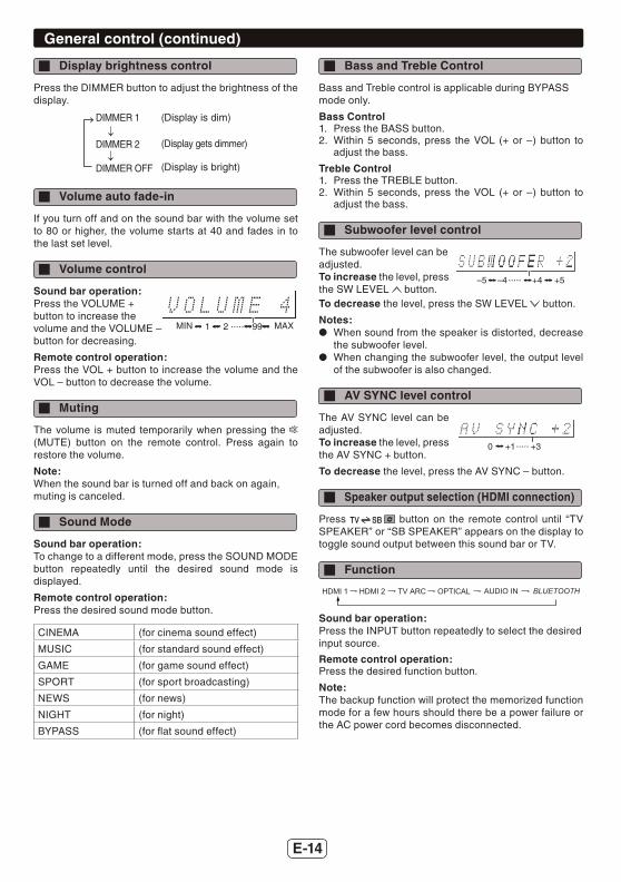
Connecting the wireless Subwoofer
The sound bar and subwoofer will link automatically (wirelessly) when turned on as it is already pre-linked at the factory. If the link cannot be established, please set the connection by the following method.
1. Press and hold the PAIRING button on the sound bar or SW LINK on the remote control for more than 3 seconds.
2. Within 2 minutes, press and hold the SW LINK button on the subwoofer for more than 3 seconds.
During pairing process:On sound bar: “SW LINK” will blink.On subwoofer: indicator will blink in blue.
When pairing is successful:On sound bar: “SW LINK” disappears.On subwoofer: indicator turns blue.
SW LINK
SW LINK
Sound Bar Remote Control
Subwoofer
Notes: If a device such as microwave oven, wireless LAN card,
Bluetooth device or any other device that uses the same 2.4GHz frequency near the system, some sound interruption may be heard due to interference.
The transmission distance of the wireless signal between the subwoofer and sound bar is about 32 feet (10m), but may vary depending on your operating environment. If a steel-concrete or metallic wall is between the subwoofer and the sound bar, the system may not operate at all, because the wireless signal cannot penetrate metal.
Caution: Keep the subwoofer away from water and moisture. To get the optimum listening performance, make sure
the area around the sound bar and subwoofer is clear of any obstacles.
E-14
General control (continued)
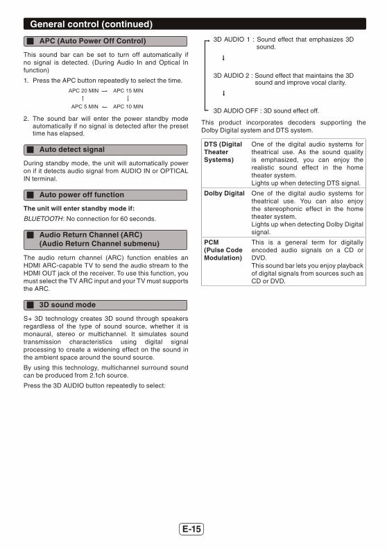
Display brightness control
Press the DIMMER button to adjust the brightness of the display.
(Display is dim)
(Display gets dimmer)
(Display is bright)
DIMMER 1
DIMMER 2
DIMMER OFF
Volume auto fade-in
If you turn off and on the sound bar with the volume set to 80 or higher, the volume starts at 40 and fades in to the last set level.
Volume control
Sound bar operation:Press the VOLUME +button to increase thevolume and the VOLUME –button for decreasing.
MIN MAX2 99.....1
Remote control operation:Press the VOL + button to increase the volume and the VOL – button to decrease the volume.
Muting
The volume is muted temporarily when pressing the (MUTE) button on the remote control. Press again to restore the volume.
Note:When the sound bar is turned off and back on again,muting is canceled.
Sound Mode
Sound bar operation:To change to a different mode, press the SOUND MODE button repeatedly until the desired sound mode is displayed.
Remote control operation:Press the desired sound mode button.
CINEMA (for cinema sound effect)
MUSIC (for standard sound effect)
GAME (for game sound effect)
SPORT (for sport broadcasting)
NEWS (for news)
NIGHT (for night)
BYPASS (for fl at sound effect)
Bass and Treble Control
Bass and Treble control is applicable during BYPASSmode only.
Bass Control1. Press the BASS button.2. Within 5 seconds, press the VOL (+ or –) button to
adjust the bass.
Treble Control1. Press the TREBLE button.2. Within 5 seconds, press the VOL (+ or –) button to
adjust the bass.
Subwoofer level control
The subwoofer level can beadjusted.To increase the level, press the SW LEVEL button.
+5–5 –4 +4.....
To decrease the level, press the SW LEVEL button.
Notes: When sound from the speaker is distorted, decrease
the subwoofer level. When changing the subwoofer level, the output level
of the subwoofer is also changed.
AV SYNC level control
The AV SYNC level can be adjusted.To increase the level, press the AV SYNC + button.
0 +1 +3.....
To decrease the level, press the AV SYNC – button.
Speaker output selection (HDMI connection)
Press button on the remote control until “TV SPEAKER” or “SB SPEAKER” appears on the display to toggle sound output between this sound bar or TV.
Function
TV ARCHDMI 2 OPTICAL AUDIO INHDMI 1 BLUETOOTH
Sound bar operation: Press the INPUT button repeatedly to select the desired input source.
Remote control operation: Press the desired function button.
Note:The backup function will protect the memorized function mode for a few hours should there be a power failure or the AC power cord becomes disconnected.
E-15
General control (continued)
APC (Auto Power Off Control)
This sound bar can be set to turn off automatically if no signal is detected. (During Audio In and Optical In function)
1. Press the APC button repeatedly to select the time.
APC 15 MINAPC 20 MIN
APC 10 MINAPC 5 MIN
2. The sound bar will enter the power standby mode automatically if no signal is detected after the preset time has elapsed.
Auto detect signal
During standby mode, the unit will automatically power on if it detects audio signal from AUDIO IN or OPTICAL IN terminal.
Auto power off function
The unit will enter standby mode if:
BLUETOOTH : No connection for 60 seconds.
Audio Return Channel (ARC) (Audio Return Channel submenu)
The audio return channel (ARC) function enables an HDMI ARC-capable TV to send the audio stream to the HDMI OUT jack of the receiver. To use this function, you must select the TV ARC input and your TV must supports the ARC.
3D sound mode
S+ 3D technology creates 3D sound through speakers regardless of the type of sound source, whether it is monaural, stereo or multichannel. It simulates sound transmission characteristics using digital signal processing to create a widening effect on the sound in the ambient space around the sound source.
By using this technology, multichannel surround sound can be produced from 2.1ch source.
Press the 3D AUDIO button repeatedly to select:
3D AUDIO 1 : Sound effect that emphasizes 3Dsound.
3D AUDIO 2 : Sound effect that maintains the 3Dsound and improve vocal clarity.
3D AUDIO OFF : 3D sound effect off.
This product incorporates decoders supporting the Dolby Digital system and DTS system.
DTS (Digital Theater Systems)
One of the digital audio systems for theatrical use. As the sound quality is emphasized, you can enjoy the realistic sound effect in the home theater system.Lights up when detecting DTS signal.
Dolby Digital One of the digital audio systems for theatrical use. You can also enjoy the stereophonic effect in the home theater system.Lights up when detecting Dolby Digital signal.
PCM(Pulse Code Modulation)
This is a general term for digitally encoded audio signals on a CD or DVD.This sound bar lets you enjoy playback of digital signals from sources such as CD or DVD.
E-16
Bluetooth one touch connection via NFC
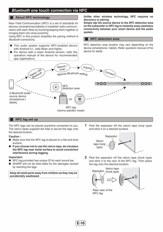
About NFC technology
Near Field Communication (NFC) is a set of standards for devices (smartphones/tablets) to establish radio communi - cation with each other by touching/tapping them together or bringing them into close proximity.Using NFC in this product simplifi es the pairing method of Bluetooth connectivity.
This audio system supports NFC-enabled device with Android 4.1, Jelly Bean and higher.
For device with a lower Android version, refer the operation manual of the device for recommended app (application).
Unlike other wireless technology, NFC requires no discovery or pairing.Simply tap the source device to the NFC detection area on the subwoofer or NFC tag to instantly enjoy seamless connectivity between your smart device and the audio system.
NFC detection area
NFC detection area location may vary depending on the device (smartphone / tablet). Refer operation manual of the device for detail.
A Bluetooth audio source device (smartphone / tablet).
NFC tag
NFC detection area
Or
(during standby mode)
Manual Bluetooth settingSwitch ‘ON’
Bluetooth
Search / scan Pairing
Connect
NFC tag set up
The NFC tags can be placed anywhere convenient to you. The velcro tapes supplied will help to secure the tags onto the desired location.
Caution : Make sure that the NFC tag is placed on a fl at and level
surface. If you choose not to use the velcro tape, do not place
the NFC tag near metal surface to avoid connection interference during tagging.
Important: NFC tag provided has unique ID for each sound bar. SHARP will not be held liable for the damages caused
by rewriting the tags.
Keep all small parts away from children as they may be accidentally swallowed.
1 Peel the separator off the velcro tape (loop type) and stick it on a desired surface.
Separator
Velcro tape (loop
type)
2 Peel the separator off the velcro tape (hook type) and stick it to the rear of the NFC tag. Then place the tag onto the desired location.
Separator
Rear view of the NFC tag
Velcro tape (hook type)
E-17
Bluetooth one touch connection via NFC (continued)
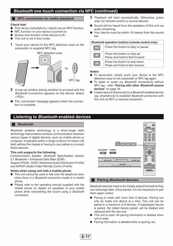
NFC connection for audio playback
Check that: Your device (smartphone / tablet) has an NFC function. NFC function on your device is turned on. Screen lock function of the device is off. This unit is not in Eco mode.
1 Touch your device to the NFC detection area on the subwoofer or supplied NFC tag.
NFC tag
NFC detection area
Or
2 A pop-up window asking whether to proceed with the Bluetooth connection appears on the device. Select <YES>.
The ‘connected’ message appears when the connec- tion is complete.
3 Playback will start automatically. Otherwise, press play (on remote control or source device).
Sound will be heard from the speakers of this unit via audio streaming.
Your device must be within 10 meters from the sound bar.
Bluetooth operation buttons (remote control only)
Press the button to play or pause.
Press the button to skip up.Press and hold to fast forward.
Press the button to skip down.Press and hold to fast reverse.
Notes: To disconnect, simply touch your device to the NFC
detection area on the subwoofer or NFC tag again. To listen to audio via Bluetooth connectivity without
NFC tag - refer “Pairing with other Bluetooth source devices” on page 18.
It takes about 6-8 seconds for a Bluetooth enabled device (eg. smartphone) to establish Bluetooth connection with this unit via NFC or manual connection.
Listening to Bluetooth enabled devices
Bluetooth
Bluetooth wireless technology is a short-range radio technology that enables wireless communication between various types of digital devices, such as mobile phone or computer. It operates within a range of about 10 meters (30 feet) without the hassle of having to use cables to connect these devices.
This unit supports the following:Communication System: Bluetooth Specifi cation version 2.1 Bluetooth + Enhanced Data Rate (EDR).Support Profi le : A2DP (Advanced Audio Distribution Profi le) and AVRCP (Audio/Video Remote Control Profi le)
Notes when using unit with a mobile phone This unit cannot be used to talk over the telephone even
when there is a Bluetooth connection made to a mobile phone.
Please refer to the operating manual supplied with the mobile phone for details on operation of your mobile phone while transmitting the sound using a Bluetooth connection.
Pairing Bluetooth devices
Bluetooth devices need to be initially paired fi rst before they can exchange data. Once paired, it is not necessary to pair them again unless:
Pairing is made with more than 8 devices. Pairing can only be made one device at a time. This unit can be paired to a maximum of 8 devices. If subsequent device is paired, the oldest device paired, will be deleted and replaced with the new one.
This unit is reset. All pairing information is deleted when unit is reset.
Pairing information is deleted while re-pairing, etc.
E-18
Listening to Bluetooth enabled devices (continued)Indicators:
Indicator Condition Bluetooth status
Blinks In waiting or pairing mode
Lights up Connected
No indication Unconnected
However, the indication status is not displayed during standby mode.
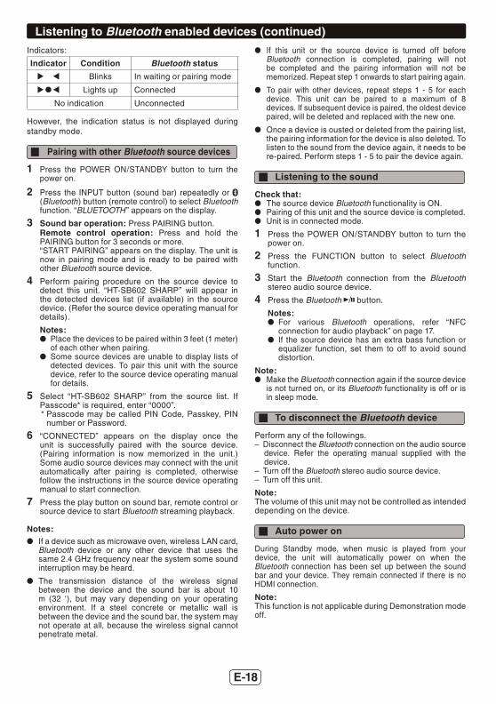
Pairing with other Bluetooth source devices
1 Press the POWER ON/STANDBY button to turn the power on.
2 Press the INPUT button (sound bar) repeatedly or (Bluetooth) button (remote control) to select Bluetooth function. “BLUETOOTH ” appears on the display.
3 Sound bar operation: Press PAIRING button.Remote control operation: Press and hold the PAIRING button for 3 seconds or more.“START PAIRING” appears on the display. The unit is now in pairing mode and is ready to be paired with other Bluetooth source device.
4 Perform pairing procedure on the source device to detect this unit. “HT-SB602 SHARP” will appear in the detected devices list (if available) in the source device. (Refer the source device operating manual for details).
Notes: Place the devices to be paired within 3 feet (1 meter) of each other when pairing.
Some source devices are unable to display lists of detected devices. To pair this unit with the source device, refer to the source device operating manual for details.
5 Select “HT-SB602 SHARP” from the source list. If Passcode* is required, enter “0000”.* Passcode may be called PIN Code, Passkey, PIN
number or Password.
6 “CONNECTED” appears on the display once the unit is successfully paired with the source device. (Pairing information is now memorized in the unit.) Some audio source devices may connect with the unit automatically after pairing is completed, otherwise follow the instructions in the source device operating manual to start connection.
7 Press the play button on sound bar, remote control or source device to start Bluetooth streaming playback.
Notes: If a device such as microwave oven, wireless LAN card,
Bluetooth device or any other device that uses the same 2.4 GHz frequency near the system some sound interruption may be heard.
The transmission distance of the wireless signal between the device and the sound bar is about 10 m (32 ‘), but may vary depending on your operating environment. If a steel concrete or metallic wall is between the device and the sound bar, the system may not operate at all, because the wireless signal cannot penetrate metal.
If this unit or the source device is turned off before Bluetooth connection is completed, pairing will not be completed and the pairing information will not be memorized. Repeat step 1 onwards to start pairing again.
To pair with other devices, repeat steps 1 - 5 for each device. This unit can be paired to a maximum of 8 devices. If subsequent device is paired, the oldest device paired, will be deleted and replaced with the new one.
Once a device is ousted or deleted from the pairing list, the pairing information for the device is also deleted. To listen to the sound from the device again, it needs to be re-paired. Perform steps 1 - 5 to pair the device again.
Listening to the sound
Check that: The source device Bluetooth functionality is ON. Pairing of this unit and the source device is completed. Unit is in connected mode.
1 Press the POWER ON/STANDBY button to turn the power on.
2 Press the FUNCTION button to select Bluetooth function.
3 Start the Bluetooth connection from the Bluetooth stereo audio source device.
4 Press the Bluetooth / button.
Notes: For various Bluetooth operations, refer “NFC connection for audio playback” on page 17.
If the source device has an extra bass function or equalizer function, set them to off to avoid sound distortion.
Note: Make the Bluetooth connection again if the source device
is not turned on, or its Bluetooth functionality is off or is in sleep mode.
To disconnect the Bluetooth device
Perform any of the followings.– Disconnect the Bluetooth connection on the audio source
device. Refer the operating manual supplied with the device.
– Turn off the Bluetooth stereo audio source device.– Turn off this unit.
Note:The volume of this unit may not be controlled as intended depending on the device.
Auto power on
During Standby mode, when music is played from your device, the unit will automatically power on when the Bluetooth connection has been set up between the sound bar and your device. They remain connected if there is no HDMI connection.
Note:This function is not applicable during Demonstration mode off.
E-19
Operating the TV with the remotecontrol
You can operate Sharp TVs with this system’s remote control.
Watching TV
Point the remote control at the TV.1 Press the TV ( ) ON/STANDBY button to turn
on the TV.
2 Pressing the TV CH + or – button enables TV channel switching.
3 Press the TV VOL + or – button to adjust the TV volume.
Other operable button
Input Select Button
Mute (TV)
AV mode
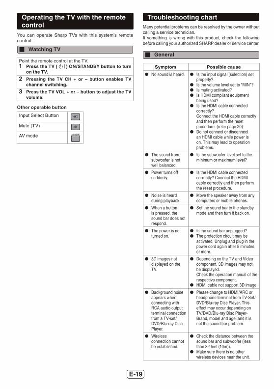
Troubleshooting chartMany potential problems can be resolved by the owner without calling a service technician.If something is wrong with this product, check the following before calling your authorized SHARP dealer or service center.
General
Symptom Possible cause
No sound is heard. Is the input signal (selection) set properly?
Is the volume level set to “MIN”? Is muting activated? Is HDMI compliant equipment
being used? Is the HDMI cable connected
correctly?Connect the HDMI cable correctly and then perform the reset procedure. (refer page 20)
Do not connect or disconnect an HDMI cable while power is on. This may lead to operation problems.
The sound from subwoofer is not well balanced.
Is the subwoofer level set to the minimum or maximum level?
Power turns off suddenly.
Is the HDMI cable connected correctly? Connect the HDMI cable correctly and then perform the reset procedure.
Noise is heard during playback.
Move the speaker away from any computers or mobile phones.
When a button is pressed, the sound bar does not respond.
Set the sound bar to the standby mode and then turn it back on.
The power is not turned on.
Is the sound bar unplugged? The protection circuit may be
activated. Unplug and plug in the power cord again after 5 minutes or more.
3D images not displayed on the TV.
Depending on the TV and Video component, 3D images may not be displayed.Check the operation manual of the respective component.
HDMI cable not support 3D image.
Background noise appears when connecting with RCA audio output terminal connection from a TV-set/ DVD/Blu-ray Disc Player.
Please change to HDMI/ARC or headphone terminal from TV-Set/DVD/Blu-ray Disc Player. This effect may occur depending on TV/DVD/Blu-ray Disc Player-Brand, model and age, and it is not the sound bar problem.
Wireless connection cannot be established.
Check the distance between the sound bar and subwoofer (less than 32 feet (10m)).
Make sure there is no other wireless devices near the unit.
E-20
Troubleshooting chart (continued)
Symptom Possible cause
Wireless connection cannot be established.
Make sure there is no obstacles (especially metal) blocking between the sound bar and subwoofer.
Manually re-link the sound bar and subwoofer (refer page 13).
NFC / Bluetooth
Symptom Possible cause
No sound is heard. The unit is too far from the Bluetooth stereo audio source device.
The unit is not paired with the Bluetooth stereo audio source device.
Bluetooth sound is interrupted or distorted.
The unit is too near to a device that generates electromagnetic radiation.
There is an obstacle between the unit and the Bluetooth stereo audio source device.
NFC-enabled device cannot connect to Bluetooth via NFC tag.
Sound bar is not in Bluetooth pairing mode. Perform “NFC connection for audio playback”. (Refer page 17.)
Remote control
Symptom Possible cause
The remote control does not operate properly.
Is the battery polarity correct? Is the battery dead? Is the distance or angle incorrect? Are there any obstructions in front
of the sound bar? Is there a strong light shining on
the remote sensor? Is the remote control for another
equipment used simultaneously?
The sound bar cannot be turned on with the remote control.
Is the AC power cord of the sound bar plugged in?
Is the battery inserted?
Condensation
Sudden temperature changes, storage or operation in an extremely humid environment may cause condensation inside the cabinet or on the transmitter on the remote control. Condensation can cause the sound bar to malfunction. If this happens, leave the power on until normal playback is possible (about 1 hour). Wipe off any condensation on the transmitter with a soft cloth before operating the sound bar.
If problem occurs during operation
When this product is subject to strong external interference (mechanical shock, excessive static electricity, abnormal supply voltage due to lightning, etc.) or if it is operated incorrectly, it may malfunction.
If such a problem occurs, do the following:1. Set the sound bar to the standby mode and turn the
power on again.2. If the sound bar is not restored in the previous operation,
unplug and plug in the sound bar again, and then turn the power on.
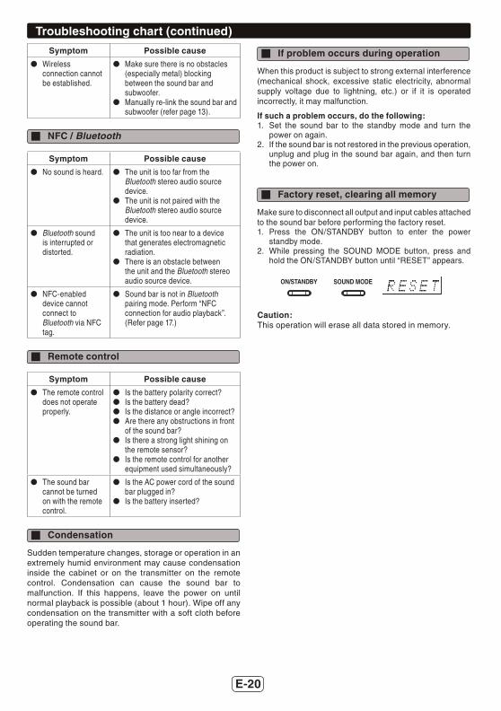
Factory reset, clearing all memory
Make sure to disconnect all output and input cables attached to the sound bar before performing the factory reset.1. Press the ON/STANDBY button to enter the power
standby mode.2. While pressing the SOUND MODE button, press and
hold the ON/STANDBY button until “RESET” appears.
Caution:This operation will erase all data stored in memory.

E-21
Maintenance
Cleaning the cabinet
Periodically wipe the cabinet with a soft cloth.Caution:
Do not use chemicals for cleaning (gasoline, paint thinner, etc.). It may damage the cabinet fi nish.
Do not apply oil to the inside of each component. It may cause malfunctions.
Error indicators and warningsWhen you fail to perform operations properly, the following messages are displayed on the sound bar.
Display Meaning
(Display blinks)
When there is no input signal.Play back the connected equipment.
Nonstandard signal. Cannot be recognized.
Signals other than DOLBY DIGITAL, DTS, Linear PCM cannot be recognized.
Poor connection of the digital audio input terminal.
Turn off the sound bar and check if the cable is connected properly.
Error indicator(blinks red)
When the protection circuit is activated.
(*): Should the same message appear even if the speaker is unplugged and plugged in, or is set to the standby mode and on again, contact your local dealer where you purchased the sound bar.
Specifi cationsAs part of our policy of continuous improvement, SHARPreserves the right to make design and specifi cation changes for product improvement without prior notice. The performance specifi cation fi gures indicated are nominal values of production unit. There maybe some deviations from these values in individual unit.
Sound Bar
Power source AC 120 V ~ 60 Hz
Powerconsumption
38 W
Dimension Width: 54 - 9/16” (1386 mm)Height: 2 - 15/16” (74 mm)Depth: 2 - 11/16” (68 mm)
Weight 7.9 lbs. (3.7 kg)
Output power RMS: Total 160 wattsRMS:Front Left/Right:80 watts per channel into 4 ohms at1 kHz, 10% total harmonic distortionFTC:Front: (Left/Right):Minimum 50 watts per channel into4 ohms at 120 Hz to 20 kHz, 1% totalharmonic distortion
Output terminal
HDMI™ output: (audio/video support up to 1080p) x 1
Input terminal 500 mV / 47 kohmsOptical digital input (OPTICAL):Square type x 1HDMI input: (audio/video support up to 1080p) x 2
Type 2 Way speaker system2 -1/4” (5.7 cm) woofer1” (2.5 cm) Soft Dome
Bluetooth Frequency band
2.400GHz - 2.480GHz
Compatible Bluetooth Profi le
A2DP (Advanced Audio DistributionProfi le), AVRCP (Audio/VideoRemote Control Profi le)Bluetooth 2.1 +EDR
Maximum input power
160 W
Rated input power
80 W
Impedance 4 ohms
Subwoofer
Power source AC 120 V ~ 60 Hz
Power consumption
33 W
Output power RMS:150 watts per channel into 3 ohms at 100 Hz, 10% total harmonic distortionFTC:Minimum 110 watts per channel into 3 ohms at 100 Hz, 1% total harmonic distortion
Type Subwoofer system6 - 5/16” (16 cm) woofer
Maximum input power
300 W
Rated input power
150 W
Impedance 3 ohms
Dimensions Width: 5 - 11/16” (144 mm)Height: 17” (432 mm)Depth: 12 - 1/16” (306 mm)
Weight 13.4 lbs. (6.1 kg)