Embed Size (px)
Citation preview

SOUND BAR SYSTEM
MODEL
HT-SB500OPERATION MANUAL
Thank you for purchasing this SHARP product. To obtain the bestperformance from this product, please read this manual carefully. Itwill guide you in operating your SHARP product.
Note:This product is recommended for flat panel TV (LCD andplasma).
SRS TruSurround HDTM creates an immersive, feature-rich surround sound experience from two speakers, complete with rich bass, high frequency detail and clear dialog.
is a trademark of SRS Labs, Inc.
TruSurround HD technology is incorporated under licensefrom SRS Labs, Inc.
HT-SB500Im
port
ant I
nstr
uctio
n
2
2009 October 29 HT-SB500_A6_EN_US.fm
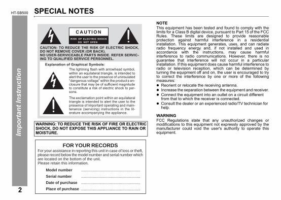
SPECIAL NOTESNOTEThis equipment has been tested and found to comply with thelimits for a Class B digital device, pursuant to Part 15 of the FCCRules. These limits are designed to provide reasonableprotection against harmful interference in a residentialinstallation. This equipment generates, uses, and can radiateradio frequency energy and, if not installed and used inaccordance with the instructions, may cause harmfulinterference to radio communications. However, there is noguarantee that interference will not occur in a particularinstallation. If this equipment does cause harmful interference toradio or television reception, which can be determined byturning the equipment off and on, the user is encouraged to tryto correct the interference by one or more of the followingmeasures:
Reorient or relocate the receiving antenna.Increase the separation between the equipment and receiver.Connect the equipment into an outlet on a circuit different from that to which the receiver is connected.Consult the dealer or an experienced radio/TV technician for help.
WARNINGFCC Regulations state that any unauthorized changes ormodifications to this equipment not expressly approved by themanufacturer could void the user's authority to operate thisequipment.
WARNING: TO REDUCE THE RISK OF FIRE OR ELECTRIC SHOCK, DO NOT EXPOSE THIS APPLIANCE TO RAIN OR MOISTURE.
CAUTION: TO REDUCE THE RISK OF ELECTRIC SHOCK,DO NOT REMOVE COVER (OR BACK).NO USER-SERVICEABLE PARTS INSIDE. REFER SERVIC-ING TO QUALIFIED SERVICE PERSONNEL.
Explanation of Graphical Symbols:The lightning flash with arrowhead symbol,within an equilateral triangle, is intended toalert the user to the presence of uninsulated“dangerous voltage” within the product s en-closure that may be of sufficient magnitudeto constitute a risk of electric shock to per-sons.
The exclamation point within an equilateraltriangle is intended to alert the user to thepresence of important operating and main-tenance (servicing) instructions in the lit-erature accompanying the appliance.
FOR YOUR RECORDSFor your assistance in reporting this unit in case of loss or theft,please record below the model number and serial number whichare located on the bottom of the unit.Please retain this information.
Model number .......................................................
Serial number .......................................................
Date of purchase .......................................................
Place of purchase .......................................................

2009 October 29 HT-SB500_A6_EN_US.fm
10) Protect the power cord from being walked on or pinchedparticularly at plugs, convenience receptacles, and the pointwhere they exit from the apparatus.
11) Only use attachments/accessories specified by themanufacturer.
HT-SB500
Impo
rtan
t Ins
truc
tion
IMPORTANT SAFETY INSTRUCTIONSElectricity is used to perform many useful functions, but it canalso cause personal injuries and property damage if improperlyhandled. This product has been engineered and manufacturedwith the highest priority on safety. However, improper use canresult in electric shock and/or fire. In order to prevent potentialdanger, please observe the following instructions wheninstalling, operating and cleaning the product. To ensure yoursafety and prolong the service life of this product, please readthe following precautions carefully before use.1) Read these instructions.2) Keep these instructions.3) Heed all warnings.4) Follow all instructions.5) Do not use this apparatus near water.6) Clean only with dry cloth.7) Do not block any ventilation openings. Install in accordance
with the manufacturer's instructions.8) Do not install near any heat sources such as radiators, heat
registers, stoves, or other apparatus (including amplifiers)that produce heat.
9) Do not defeat the safety purpose of the polarized orgrounding-type plug. A polarized plug has two blades withone wider than the other. A grounding type plug has twoblades and a third grounding prong. The wide blade or thethird prong are provided for your safety. If the provided plugdoes not fit into your outlet, consult an electrician forreplacement of the obsolete outlet.
12) Use only with the cart, stand, tripod, bracket, or tablespecified by the manufacturer, or sold with the apparatus.When a cart is used, use caution when moving the cart/apparatus combination to avoid injury from tip-over.
13) Unplug this apparatus during lightning storms or whenunused for long periods of time.
14) Refer all servicing to qualified service personnel. Servicingis required when the apparatus has been damaged in anyway, such as power-supply cord or plug is damaged, liquidhas been spilled or objects have fallen into the apparatus,the apparatus has been exposed to rain or moisture, doesnot operate normally, or has been dropped.
Additional Safety Information
15) Power Sources - This product should be operated only fromthe type of power source indicated on the marking label. Ifyou are not sure of the type of power supply to your home,consult your product dealer or local power company. Forproduct intended to operate from battery power, or othersources, refer to the operating instructions.
16) Overloading - Do not overload wall outlets, extension cords,or integral convenience receptacles as this can result in arisk of fire or electric shock.
17) Object and Liquid Entry - Never push objects of any kind intothis product through openings as they may touch dangerousvoltage points or short-out parts that could result in a fire orelectric shock. Never spill liquid of any kind on the product.
3

HT-SB500Im
port
ant I
nstr
uctio
n
4
IMPORTANT SAFETY INSTRUCTIONS (continued)18) Damage Requiring Service - Unplug this product from the
wall outlet and refer servicing to qualified service personnelunder the following conditions:
a) When the AC cord or plug is damaged,b) If liquid has been spilled, or objects have fallen into the
product,c) If the product has been exposed to rain or water,d) If the product does not operate normally by following
the operating instructions. Adjust only those controlsthat are covered by the operating instructions as animproper adjustment of other controls may result indamage and will often require extensive work by aqualified technician to restore the product to its normaloperation,
e) If the product has been dropped or damaged in anyway, and
f ) When the product exhibits a distinct change inperformance - this indicates a need for service.
19) Replacement Parts - When replacement parts are required,be sure the service technician has used replacement partsspecified by the manufacturer or have the samecharacteristics as the original part. Unauthorizedsubstitutions may result in fire, electric shock, or otherhazards.
20) Safety Check - Upon completion of any service or repairs tothis product, ask the service technician to perform safetychecks to determine that the product is in proper operatingcondition.
21) Wall or ceiling mounting - When mounting the product on awall or ceiling, be sure to install the product according to themethod recommended by the manufacturer.
22) Power Lines - An outside antenna system should not belocated in the vicinity of overhead power lines or otherelectric light or power circuits, or where it can fall into suchpower lines or circuits. When installing an outside antennasystem, extreme care should be taken to keep from touchingsuch power lines or circuits as contact with them might befatal.
23) Outdoor Antenna Grounding - If an outside antenna or cablesystem is connected to the product, be sure the antenna orcable system is grounded so as to provide some protectionagainst voltage surges and built-up static charges.Article810 of the National Electrical Code, ANSI/NFPA 70,provides information with regards to proper grounding of themast and supporting strcorducture, grounding of the lead-inwire to an antenna discharge unit, connection to groundingelectrodes, and requirements for the grounding electrode.
24) Protective Attachment Plug - The product is equipped withan attachment plug having overload protection. This is asafety feature. See Instruction Manual for replacement orresetting of protective device. If replacement of the plug isrequired, be sure the service technician has used areplacement plug specified by the manufacturer that has thesame overload protection as the original plug.
25) Stand - Do not place the product on an unstable cart, stand,tripod or table. Placing the product on an unstable base cancause the product to fall, resulting in serious personalinjuries as well as damage to the product. Use only a cart,stand, tripod, bracket or table recommended by themanufacturer or sold with the product. When mounting theproduct on a wall, be sure to follow the manufacturer'sinstructions. Use only the mounting hardwarerecommended by the manufacturer.
2009 October 29 HT-SB500_A6_EN_US.fm

HT-SB500
Gen
eral
Info
rmat
ion
5
2009 October 29 HT-SB500_A6_EN_US.fm
AccessoriesPlease confirm that only the following accessories are included.
Note:The AC/DC adaptor may be different from the one in the drawing.
ContentsPage
General InformationPrecautions . . . . . . . . . . . . . . . . . . . . . . . . . . . . . . . . . . 6Controls and indicators . . . . . . . . . . . . . . . . . . . . . . 7 - 9
Preparation for UseSpeaker preparation . . . . . . . . . . . . . . . . . . . . . . 10 - 12Placing the speaker . . . . . . . . . . . . . . . . . . . . . . . . . . 13Falling prevention . . . . . . . . . . . . . . . . . . . . . . . . . . . . 14Speaker connections to TVs . . . . . . . . . . . . . . . . 14 - 16AC power connection . . . . . . . . . . . . . . . . . . . . . . . . 17Remote control . . . . . . . . . . . . . . . . . . . . . . . . . . . . . . 18
Basic OperationGeneral control . . . . . . . . . . . . . . . . . . . . . . . . . . . 19 - 21
ReferencesTroubleshooting chart . . . . . . . . . . . . . . . . . . . . . . . . 22Maintenance . . . . . . . . . . . . . . . . . . . . . . . . . . . . . . . . 23Error indicators and warnings . . . . . . . . . . . . . . . . . 24Specifications . . . . . . . . . . . . . . . . . . . . . . . . . . . . . . . 25CONSUMER LIMITED WARRANTY . . . . . . . Back cover
Remote control x 1(RRMCGA200AWSA)
RCA cable (2 pins - 2 pins) x 1(QCNWGA041AWPZ))
Spike x 4 (length: 25 mm)(GLEGMA005AWSA)
Foot cushion x 4(PCUSSA118AWZZ)
AC power lead x 1(QACCDA005AWZZ)
AC/DC adaptor x 1(RADPAA061AWZZ)
Wall mount angle x 2(LANGKA167AW01)
(Spike + Nut) x 4 (length: 30 mm)(GLEGMA004AWSA)
Pattern paper x 1(TCAUHA023AWZZ)
Nut
ENERGY STAR® Program Information
ENERGY STAR® is a U.S. registered mark.
Products that have earned the ENERGY STAR® are designed to protect the environment through superior energy efficiency.
HT-SB500G
ener
al In
form
atio
n
6
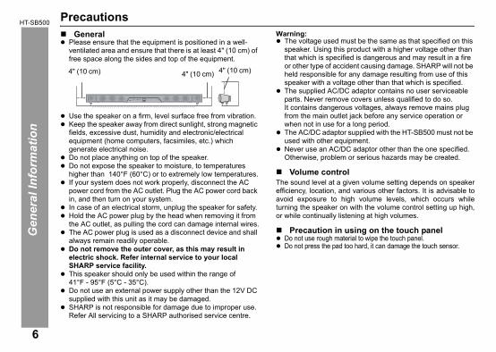
PrecautionsGeneral
Please ensure that the equipment is positioned in a well-ventilated area and ensure that there is at least 4" (10 cm) of free space along the sides and top of the equipment.
Use the speaker on a firm, level surface free from vibration.Keep the speaker away from direct sunlight, strong magnetic fields, excessive dust, humidity and electronic/electrical equipment (home computers, facsimiles, etc.) which generate electrical noise.Do not place anything on top of the speaker.Do not expose the speaker to moisture, to temperatures higher than 140°F (60°C) or to extremely low temperatures.If your system does not work properly, disconnect the AC power cord from the AC outlet. Plug the AC power cord back in, and then turn on your system.In case of an electrical storm, unplug the speaker for safety.Hold the AC power plug by the head when removing it from the AC outlet, as pulling the cord can damage internal wires.The AC power plug is used as a disconnect device and shall always remain readily operable.Do not remove the outer cover, as this may result in electric shock. Refer internal service to your local SHARP service facility.This speaker should only be used within the range of
Warning:The voltage used must be the same as that specified on this speaker. Using this product with a higher voltage other than that which is specified is dangerous and may result in a fire or other type of accident causing damage. SHARP will not be held responsible for any damage resulting from use of this speaker with a voltage other than that which is specified.The supplied AC/DC adaptor contains no user serviceable parts. Never remove covers unless qualified to do so.It contains dangerous voltages, always remove mains plug from the main outlet jack before any service operation or when not in use for a long period.The AC/DC adaptor supplied with the HT-SB500 must not be used with other equipment.Never use an AC/DC adaptor other than the one specified. Otherwise, problem or serious hazards may be created.
Volume controlThe sound level at a given volume setting depends on speakerefficiency, location, and various other factors. It is advisable toavoid exposure to high volume levels, which occurs whileturning the speaker on with the volume control setting up high,or while continually listening at high volumes.
Precaution in using on the touch panelDo not use rough material to wipe the touch panel.Do not press the pad too hard, it can damage the touch sensor.
4" (10 cm)4" (10 cm) 4" (10 cm)
2009 October 29 HT-SB500_A6_EN_US.fm
41°F - 95°F (5°C - 35°C).Do not use an external power supply other than the 12V DC supplied with this unit as it may be damaged.SHARP is not responsible for damage due to improper use. Refer All servicing to a SHARP authorised service centre.
2009 October 29 HT-SB500_A6_EN_US.fm
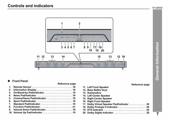
7. Standard Pad/Indicator . . . . . . . . . . . . . . . . . . . . . . . . 198. Function Pad/Indicator . . . . . . . . . . . . . . . . . . . . . . . . 219. Volume Down Pad/Indicator . . . . . . . . . . . . . . . . . . . . 1910. Volume Up Pad/Indicator . . . . . . . . . . . . . . . . . . . . . . 19
16. Right Front Speaker17. Dolby Virtual Speaker Pad/Indicator . . . . . . . . . . . . 2018. Dolby Prologic II Indicator. . . . . . . . . . . . . . . . . . . . . 2019. DTS Indicator . . . . . . . . . . . . . . . . . . . . . . . . . . . . . . . 2020. Dolby Digital Indicator . . . . . . . . . . . . . . . . . . . . . . . . 20
HT-SB500
Gen
eral
Info
rmat
ion
Controls and indicators
Front PanelReference page
1. Remote Sensor . . . . . . . . . . . . . . . . . . . . . . . . . . . . . . 182. Information Display. . . . . . . . . . . . . . . . . . . . . . . . . . . 193. On/Stand-by Pad/Indicator . . . . . . . . . . . . . . . . . . . . . 194. News Pad/Indicator . . . . . . . . . . . . . . . . . . . . . . . . . . . 195. Cinema/Game Pad/Indicator. . . . . . . . . . . . . . . . . . . . 196. Sport Pad/Indicator . . . . . . . . . . . . . . . . . . . . . . . . . . . 19
Reference page11. Left Front Speaker12. Bass Reflex Duct13. Subwoofers14. Left Center Speaker15. Right Center Speaker
11 12 12 1614 1513 13
1 2
43 5 6 7 8 910
1718
1920
7

HT-SB500G
ener
al In
form
atio
n
8
Rear PanelReference page
1. Audio Line In 2 Jack . . . . . . . . . . . . . . . . . . . . . . . . . . 152. Line In 1 Jacks . . . . . . . . . . . . . . . . . . . . . . . . . . . . . . . 153. DC Input Jack . . . . . . . . . . . . . . . . . . . . . . . . . . . . . . . . 174. Subwoofer Pre-Out Jack . . . . . . . . . . . . . . . . . . . . . . . 135. Optical Digital Audio Input Jack . . . . . . . . . . . . . . . . 166. Coaxial Digital Audio Input Jack. . . . . . . . . . . . . . . . . 16
1 42 3 5 6
2009 October 29 HT-SB500_A6_EN_US.fm

2009 October 29 HT-SB500_A6_EN_US.fm
Note:Before using remote control, please remove plastic shield atbattery holder. Notes:
Some models of SHARP TV may not be operable.SHARP TV remote control will not work with HT-SB500 system.
HT-SB500
Gen
eral
Info
rmat
ion
Controls and indicators (continued)Remote Control
Reference page1. Remote Control Transmitter . . . . . . . . . . . . . . . . . . . 142. Dolby Virtual Speaker Button . . . . . . . . . . . . . . . . . . 163. Cinema/Game Button. . . . . . . . . . . . . . . . . . . . . . . . . 154. News Button . . . . . . . . . . . . . . . . . . . . . . . . . . . . . . . . 155. Volume Up Button . . . . . . . . . . . . . . . . . . . . . . . . . . . 156. Digital 1-2 Button . . . . . . . . . . . . . . . . . . . . . . . . . . . . 177. Volume Down Button . . . . . . . . . . . . . . . . . . . . . . . . . 158. Dimmer/Sens On/Off Button . . . . . . . . . . . . . . . . . . . 159. Bass/Treble Button . . . . . . . . . . . . . . . . . . . . . . . . . . 1710. TV Operation Buttons . . . . . . . . . . . . . . . . . . . . . . . . . 511. On/Stand-by Button . . . . . . . . . . . . . . . . . . . . . . . . . . 1512. Sport Button . . . . . . . . . . . . . . . . . . . . . . . . . . . . . . . . 1513. Standard Button . . . . . . . . . . . . . . . . . . . . . . . . . . . . . 1514. Line 1-2 Button . . . . . . . . . . . . . . . . . . . . . . . . . . . . . . 1715. Mute Button . . . . . . . . . . . . . . . . . . . . . . . . . . . . . . . . 1516. Subwoofer Level Up Button . . . . . . . . . . . . . . . . . . . 1717. Subwoofer Level Down Button . . . . . . . . . . . . . . . . . 1718. Center Speaker Level Up Button . . . . . . . . . . . . . . . 1719. Center Speaker Level Down Button . . . . . . . . . . . . . 17
2
345
6789
1019181716
1514
1312
11
1
Remote control
Plastic shield
Battery holder
TV Operation Buttons (Only SHARP TV):On/Stand-by Button
Sets the TV power to “ON” or “STAND-BY”.
Input Select Button (TV)
Press the button to switch the input source.
Volume Up and Down Buttons
Turn up/down the TV volume.
Channel Up and Down Buttons
Switch up/down the TV channels.
9

HT-SB500Pr
epar
atio
n fo
r Use
10
Speaker preparation
Select from three installation methods according to thepreferred position.
Notes:Option 1 or option 2 indicates spike positions based on LCD
Caution:When using these spikes on glossy or slippery table such as onglass top, stick foot cushions at the bottom of the spikes to avoidslippage.
Note:Option 1 or option 2 foot cushion positions based on LCD TVstand.
Make sure to unplug the AC power cord before installingthe speaker or changing the position.
Tighten all spikes as shown
Option 2Option 1
Using spikes
You may choose from the two different spike lengths provided:25 mm and 30 mm. Nuts (secured on 30 mm spikes) must be used when installingeither the 25 mm or 30 mm spikes.The speaker can be levelled by adjusting the spikes and nuts.
Attach foot cushions as shown
Option 1Option 2
Using foot cushions
2009 October 29 HT-SB500_A6_EN_US.fm
TV stand.When attaching the spikes, place the speaker on a cushion or soft cloth to avoid damage.

2009 October 29 HT-SB500_A6_EN_US.fm
(Continued to the next page)
HT-SB500
Prep
arat
ion
for U
se
Speaker preparation (continued)
Caution:Be very careful to prevent the speaker [4.84 lbs. (2.2 kg)] from falling when mounting on the wall.Before mounting, check the wall strength. (Do not put on the veneer plaster or whitewashed wall. The speaker may fall.) If unsure, consult a qualified service technician.Mounting screws are not supplied. Use appropriate ones.Check all wall mount angle screws for looseness.Select a good location. If not, accidents may occur or the speaker may get damaged.SHARP is not responsible for accidents resulting from improper installation.
Driving screwsSHARP designed the speakers so you may hang them on thewall. Use proper screws (not supplied). See below for size andtype.
Wall mount angle fixed to the wall(Horizontal position)To mount the speaker on the wall
1/8" (3.2 mm)
3/8" (9 mm)
Min. 7/8" (22 mm)
3/16"(5 mm)
1 Fix the pattern paper to the wall in horizontal positionas below.
2 Make a hole on the wall following the screw pointmarks on the pattern paper by using a drill.
3 Fix a wall mount plug into the hole using a hammer,until it is flush with the wall surface.
1-1/8" (29 mm)
1-1/8" (29 mm)1-3/4" (44 mm)
1-3/4" (44 mm)20-1/32" (509 mm)
Pattern paper
Wall surface
Wall surface
3/8" (8-9 mm)
1-1/4" (32 mm)
Wall surface
3/8" (8-9 mm)
1-1/4" (32 mm)
11
HT-SB500Pr
epar
atio
n fo
r Use
12
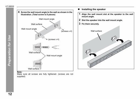
Note:Make sure all screws are fully tightened. (screws are notsupplied)
Installing the speaker4 Screw the wall mount angle to the wall as shown in the
illustration. (Total screw is 8 pieces)
Wall surface
Wall mount angle
Wall mount angle
Wall surface
Wall surface
Wall mount angle
(screws x 4)
(screws x 4)
1 Align the wall mount slot at the speaker to the wallmount angle.
2 Slot the speaker into the wall mount angle.
3 Fix them securely.
Wall surface
2009 October 29 HT-SB500_A6_EN_US.fm

2009 October 29 HT-SB500_A6_EN_US.fm
HT-SB500
Prep
arat
ion
for U
se
Placing the speakerInstallation image:
Place the speaker as shown.
Notes:As the sound from the speaker is omni-directional, you can place the speaker anywhere you like. However, it is recommended to place it as close to the TV as possible.The front panel of the speaker is not removable.
Caution:Do not change the installation direction when the speaker is turned on. Do not stand or sit on the speaker as you may be injured.
Using other subwooferYou can connect a subwoofer with an amplifier to theSUBWOOFER PRE-OUT jack.
Note:No sound is heard from the subwoofer without a built-in amplifier.
TV
VCR DVD player
Audio signal
Audio cable (commercially available)
Commercially available subwoofer
(amplifier built in)
To audio input jack
To SUBWOOFER PRE-OUT jack
Speaker
13
HT-SB500Pr
epar
atio
n fo
r Use
14
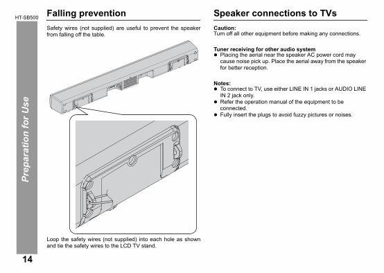
Falling preventionSafety wires (not supplied) are useful to prevent the speakerfrom falling off the table.
Speaker connections to TVsCaution:Turn off all other equipment before making any connections.
Tuner receiving for other audio systemPlacing the aerial near the speaker AC power cord may cause noise pick up. Place the aerial away from the speaker for better reception.
Notes:To connect to TV, use either LINE IN 1 jacks or AUDIO LINE IN 2 jack only.Refer the operation manual of the equipment to be connected.Fully insert the plugs to avoid fuzzy pictures or noises.
2009 October 29 HT-SB500_A6_EN_US.fm
Loop the safety wires (not supplied) into each hole as shownand tie the safety wires to the LCD TV stand.

2009 October 29 HT-SB500_A6_EN_US.fm
If the speaker volume is continuously in very high level, the speaker will mute and recover after several seconds.The information display on the sound bar system will not display anything when increasing or decreasing the volume level.
HT-SB500
Prep
arat
ion
for U
se
Speaker connections to TVs (continued) Connecting to a TV
If the TV/monitor has an audio output, connect it to the LINE IN1 jacks on the rear of the speaker.
To select LINE IN 1 function:On speaker: Press FUNCTION button repeatedly until “L1” is displayed.On remote control: Press LINE 1-2 button repeatedly until “L1” is displayed.
Connecting to a TV (with Headphone jack)If the TV/monitor has headphone jack, connect it to the LINE IN2 jack on the rear of the speaker.
To select LINE IN 2 function:On speaker: Press FUNCTION button repeatedly until “L2” is displayed.On remote control: Press LINE 1-2 button repeatedly until “L2” is displayed.
Notes:If the TV volume is continuously in low level, the speaker will automatically power off. Increase the TV output volume to enjoy the sound from the speaker.
To audio output jacks
RCA cable (supplied)
Speaker
TV
To LINE IN 1 jacks
HEADPHONE
To HEADPHONE jack
Audio cable (not supplied)
Speaker
TV
To AUDIO LINE IN 2 jack
15
HT-SB500Pr
epar
atio
n fo
r Use
16
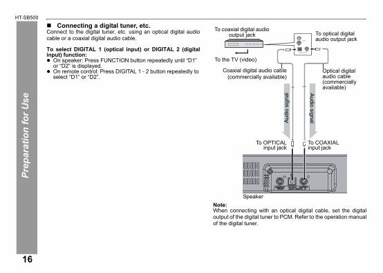
Connecting a digital tuner, etc.Connect to the digital tuner, etc. using an optical digital audiocable or a coaxial digital audio cable.
To select DIGITAL 1 (optical input) or DIGITAL 2 (digitalinput) function:
On speaker: Press FUNCTION button repeatedly until “D1” or “D2” is displayed.On remote control: Press DIGITAL 1 - 2 button repeatedly to select “D1” or “D2”.
Note:When connecting with an optical digital cable, set the digitaloutput of the digital tuner to PCM. Refer to the operation manual
Coaxial digital audio cable(commercially available)
Optical digital audio cable (commercially available)
To COAXIALinput jack
To the TV (video)
To OPTICALinput jack
Speaker
To coaxial digital audio output jack
Audio signalAu
dio
sign
al
To optical digital audio output jack
2009 October 29 HT-SB500_A6_EN_US.fm
of the digital tuner.

2009 October 29 HT-SB500_A6_EN_US.fm
HT-SB500
Prep
arat
ion
for U
se
17
AC power connectionUsing with the AC/DC adaptor
Notes:Unplug the AC/DC adaptor from the AC outlet if the speaker will not be used for a long period of time.Use only the supplied AC/DC adaptor. Using other AC/DC adaptor may cause an electric shock or fire.
1 Plug the AC power cord into the AC/DC adaptor. 2 Plug the AC/DC adaptor cable into the DC IN jack on
the speaker.3 Plug the AC power cord into a AC outlet. The STAND-
BY indicator will turn ORANGE when AC power isapplied. The power indicator will turn GREEN whenthe system in “ON”.
AC/DC Adaptor Cable
DC IN jack(DC 12 V)
AC/DC Adaptor
AC outlet(AC 100 - 240 V ~ 50/60 Hz)
AC power cord
HT-SB500Pr
epar
atio
n fo
r Use
18
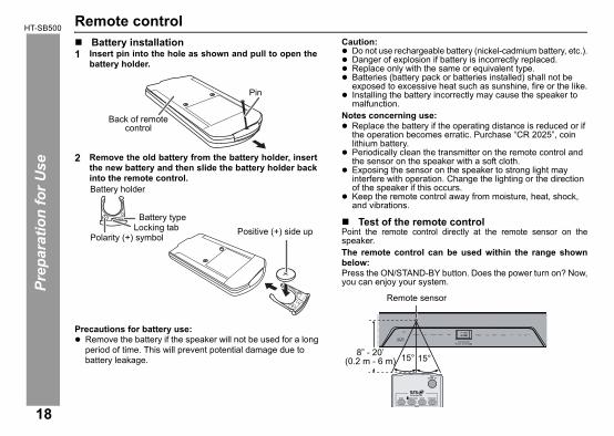
Remote controlBattery installation
Precautions for battery use:Remove the battery if the speaker will not be used for a long period of time. This will prevent potential damage due to battery leakage.
Caution:Do not use rechargeable battery (nickel-cadmium battery, etc.).Danger of explosion if battery is incorrectly replaced.Replace only with the same or equivalent type.Batteries (battery pack or batteries installed) shall not be exposed to excessive heat such as sunshine, fire or the like.Installing the battery incorrectly may cause the speaker to malfunction.
Notes concerning use:Replace the battery if the operating distance is reduced or if the operation becomes erratic. Purchase “CR 2025”, coin lithium battery. Periodically clean the transmitter on the remote control and the sensor on the speaker with a soft cloth.Exposing the sensor on the speaker to strong light may interfere with operation. Change the lighting or the direction of the speaker if this occurs.Keep the remote control away from moisture, heat, shock, and vibrations.
Test of the remote controlPoint the remote control directly at the remote sensor on thespeaker.The remote control can be used within the range shownbelow:Press the ON/STAND-BY button. Does the power turn on? Now,you can enjoy your system.
1 Insert pin into the hole as shown and pull to open thebattery holder.
2 Remove the old battery from the battery holder, insertthe new battery and then slide the battery holder backinto the remote control.
Back of remote control
Pin
Battery holder
Polarity (+) symbol
Battery typeLocking tab Positive (+) side up
15° 15°
Remote sensor
8” - 20’(0.2 m - 6 m)
2009 October 29 HT-SB500_A6_EN_US.fm

2009 October 29 HT-SB500_A6_EN_US.fm
seconds without any button/pad operation.
HT-SB500
Bas
ic O
pera
tion
General control
To turn the power onPress the ON/STAND-BY button on the remote control or touchanywhere on the display panel. All the indicators will bedisplayed to indicate pad positions.
The power indicator turns green. If the power does not turn on, check whether the power cord is plugged in properly.
To set the speaker to stand-by mode:Press the ON/STAND-BY button again on the remote control or touch ON/STAND-BY pad on the speaker.The STAND-BY indicator turns orange.
Display brightness controlPress the DIMMER ON/OFF button to adjust the brightness ofthe display and sound mode indicator.
Volume auto fade-inIf you turn off and on the speaker with the volume set to 40 orhigher, the volume starts at 20 and fades in to the last set level.
Volume control
Remote control operation:Press the VOLUME + button to increase the volume and theVOLUME – button to decrease the volume.
Preset sound modeSpeaker operation:Touch a desired sound mode on the speaker.Remote control operation:Press a desired sound mode on the remote control.
Sound mode indicator and display bright. Display will off after 5seconds without any button/pad operation.
Sound mode indicator and display dim. Display will off after 5
VOL VOL
Speaker operation:Touch volume up pad to increase thevolume and touch volume down padto decrease the volume.
MutingThe volume is muted temporarily when pressingthe MUTE button on the remote control. Pressagain to restore the volume.
NEWS TruSurround HD on for news
CINEMA/GAME TruSurround HD on for cinema/gamesound effect
SPORT TruSurround HD on for sport broadcasting
STANDARD TruSurround HD on for standard soundeffect
00 01 02 ..... 59 60
19
HT-SB500B
asic
Ope
ratio
n
20
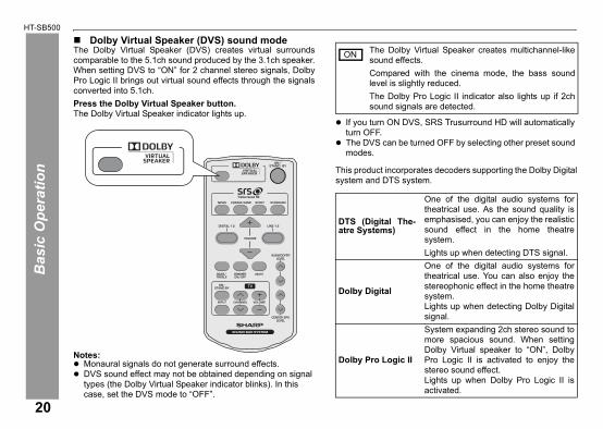
Dolby Virtual Speaker (DVS) sound modeThe Dolby Virtual Speaker (DVS) creates virtual surroundscomparable to the 5.1ch sound produced by the 3.1ch speaker.When setting DVS to “ON” for 2 channel stereo signals, DolbyPro Logic II brings out virtual sound effects through the signalsconverted into 5.1ch.Press the Dolby Virtual Speaker button.The Dolby Virtual Speaker indicator lights up.
Notes:Monaural signals do not generate surround effects.DVS sound effect may not be obtained depending on signal types (the Dolby Virtual Speaker indicator blinks). In this
If you turn ON DVS, SRS Trusurround HD will automatically turn OFF.The DVS can be turned OFF by selecting other preset sound modes.
This product incorporates decoders supporting the Dolby Digitalsystem and DTS system.
The Dolby Virtual Speaker creates multichannel-likesound effects.Compared with the cinema mode, the bass soundlevel is slightly reduced.The Dolby Pro Logic II indicator also lights up if 2chsound signals are detected.
DTS (Digital The-atre Systems)
One of the digital audio systems fortheatrical use. As the sound quality isemphasised, you can enjoy the realisticsound effect in the home theatresystem.Lights up when detecting DTS signal.
Dolby Digital
One of the digital audio systems fortheatrical use. You can also enjoy thestereophonic effect in the home theatresystem.Lights up when detecting Dolby Digitalsignal.
Dolby Pro Logic II
System expanding 2ch stereo sound tomore spacious sound. When settingDolby Virtual speaker to “ON”, DolbyPro Logic II is activated to enjoy thestereo sound effect.Lights up when Dolby Pro Logic II isactivated.
ON
2009 October 29 HT-SB500_A6_EN_US.fm
case, set the DVS mode to “OFF”.

2009 October 29 HT-SB500_A6_EN_US.fm
To turn the power on, press the ON/STAND-BY button on the remotecontrol or touch the ON/STAND-BY pad on the display panel.
HT-SB500
Bas
ic O
pera
tion
General control (continued)Subwoofer level control
Note:When sound from the speaker is distorted, decrease thesubwoofer level.
Center speaker level control
Bass control
Treble control
Touch Sensing off mode
Function
Note:The backup function will protect the memorized function modefor a few hours should there be a power failure or the AC powercord becomes disconnected.Auto power on function:When you press the LINE 1-2 or DIGITAL 1-2 button on theremote control, the speaker will turn on at last function.Auto power off and auto detect signal:
If no analogue signal is detected within 1 minute or if “D1”/“D2” display is blinking and after 30 seconds during power on, the speaker will automatically go to stand-by mode. The STANDBY indicator turns orange.The speaker will automatically power ON if it detects audio signal from connected equipment.
Note:Make sure to turn off any source/signal input to speaker beforegoing to stand-by mode because it will cause the speaker topower ON again.
The speaker level can be adjusted.To increase the level, press the SUBWOOFER LEVEL button.To decrease the level, press the SUBWOOFER LEVEL button.
The center speaker level can be adjusted.To increase the level, press the CENTER SPK LEVEL button.To decrease the level, press the CENTER SPK LEVEL button.
1. Press the BASS/TREBLE buttonto select “BASS”.
2. Within 5 seconds, press theVOLUME (+ or –) button to adjustthe bass.
1. Press the BASS/TREBLE buttonto select “TREBLE”.
2. Within 5 seconds, press theVOLUME (+ or –) button to adjustthe treble.
During Stand-by mode, press the DIMMER/SENS ON/OFF buttonon the remote control and the STAND-BY indicator will turn fromORANGE to RED.
-5 -4 ... +4 +5
-5 -4 ... +4 +5
-5 +5
-5 +5
On the speaker:When the FUNCTION pad on speakeris touched, the input source will change.Touch the FUNCTION pad on speakerrepeatedly to select desired inputsource.On remote control:Press the LINE 1-2 button repeatedly toselect “L1” (LINE IN 1 input) or “L2”(LINE IN 2 input).Press the DIGITAL 1-2 buttonrepeatedly to select “D1” (DIGITAL IN 1input) or “D2” (DIGITAL IN 2 input).
LINE 1
LINE 2
DIGITAL 1
DIGITAL 2
21

HT-SB500R
efer
ence
s
22
Troubleshooting chartMany potential problems can be resolved by the owner without callinga service technician.If something is wrong with this product, check the following beforecalling your authorised SHARP dealer or service centre.
General
Remote control
Symptom Possible causeNo sound is heard. Is the input signal (selection) set
properly?Is the volume level set to “0”?Is muting activated?
Noise is heard during playback.
Move the speaker away from any computers or mobile phones.
When a button is pressed, the speaker does not respond.
Set this speaker to the stand-by mode and then turn it back on.
The power is not turned on.
Is the speaker unplugged? (Refer to page 17)The protection circuit may beactivated. Unplug and plug in the power cord again after 5 minutes or more.
The information is notdisplayed even if theunit is turned on.
Is the unit set to “Dimmer display off” mode?
Symptom Possible causeThe remote control does not operate properly.
Is the battery polarity correct?Is the battery dead?Is the distance or angle incorrect?Are there any obstructions in front of the speaker?Is there a strong light shining on the remote sensor?Is the remote control for another equipment used simultaneously?
The speaker cannot be turned on with the remote control.
Is the AC power cord of the speaker plugged in?Is the battery inserted?
TV cannot be operated with the remote control.
Depending on the model, some or all functions may not be operable using the remote control of this speaker. In this case, use the remote control supplied with the TV.
2009 October 29 HT-SB500_A6_EN_US.fm
2009 October 29 HT-SB500_A6_EN_US.fm
HT-SB500
Ref
eren
ces
CondensationSudden temperature changes, storage or operation in an extremelyhumid environment may cause condensation inside the cabinet or onthe transmitter on the remote control.Condensation can cause the speaker to malfunction. If this happens,leave the power on until normal operation is possible (about 1 hour).Wipe off any condensation on the transmitter with a soft cloth beforeoperating the speaker.
If problem occursWhen this product is subjected to strong external interference(mechanical shock, excessive static electricity, abnormal supply voltagedue to lightning, etc.) or if it is operated incorrectly, it may malfunction.If such a problem occurs, do the following:1. Set the speaker to the stand-by mode and turn the power on again.2. If the speaker is not restored in the previous operation, unplug
and plug in the speaker, and then turn the power on.
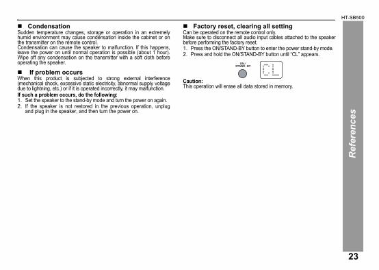
Factory reset, clearing all settingCan be operated on the remote control only.Make sure to disconnect all audio input cables attached to the speakerbefore performing the factory reset.1. Press the ON/STAND-BY button to enter the power stand-by mode.2. Press and hold the ON/STAND-BY button until “CL” appears.
Caution:This operation will erase all data stored in memory.
23
HT-SB500R
efer
ence
s
24
Maintenance
Cleaning the cabinetPeriodically wipe the cabinet with a soft cloth.Caution:
Do not use chemicals for cleaning (petrol, paint thinner, etc.). It may damage the cabinet finish.Do not apply oil to the inside of each component. It may cause malfunctions.
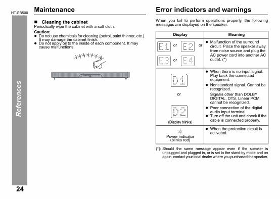
Error indicators and warningsWhen you fail to perform operations properly, the followingmessages are displayed on the speaker.
(*): Should the same message appear even if the speaker isunplugged and plugged in, or is set to the stand-by mode and onagain, contact your local dealer where you purchased the speaker.
Display Meaning
or orMalfunction of the surround circuit. Place the speaker away from noise source and plug the AC power cord into another AC outlet. (*)or
(Display blinks)
When there is no input signal. Play back the connected equipment.Nonstandard signal. Cannot be recognized.
Signals other than DOLBY DIGITAL, DTS, Linear PCM cannot be recognized. Poor connection of the digital audio input terminal.Turn off the unit and check if the cable is connected properly.
Power indicator(blinks red)
When the protection circuit is activated.
or
2009 October 29 HT-SB500_A6_EN_US.fm
2009 October 29 HT-SB500_A6_EN_US.fm
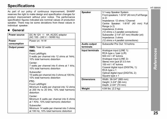
Minimum 6 watts per channel into 6 ohmsat 1 KHz, 10% total harmonic distortionSubwoofer: Minimum 14 watts per channel into 3 ohmsat 100 Hz, 10% total harmonic distortion
HT-SB500
Ref
eren
ces
SpecificationsAs part of our policy of continuous improvement, SHARPreserves the right to make design and specification changes forproduct improvement without prior notice. The performancespecification figures indicated are nominal values of productionspeaker. There may be some deviations from these values inindividual speaker.
GeneralPower source DC IN 12V 4A: AC/DC adaptor
(AC 100 - 240 V ~ 50/60 Hz)Powerconsumption
Power on: 14 W
Output power RMS: Total 32 wattsRMS:Front Left/Right:5 watts per channel into 12 ohms at 1kHz,10% total harmonic distortionCenter:7 watts per channel into 6 ohms at 1 kHz,10% total harmonic distortionSubwoofer:15 watts per channel into 3 ohms at 100 Hz,10% total harmonic distortionFTC:Front Left/Right:Minimum 4 watts per channel into 12 ohmsat 200 Hz to 20 kHz, 10% total harmonicdistortionCenter:
Speaker 3.1-way Speaker SystemFront speakers: 1-9/16" (40 mm) Full Range (x 2)Impedance: 12 ohms / ChannelCentre Speaker: 1-9/16" (40 mm) FullRange (x 2)Impedance: 6 ohms (12 ohms x 2 parallel connections)Subwoofer: 2-1/4" (57 mm) Woofer (x4)Impedance: 3 ohms (12 ohms x 4 parallel connections)
Audio output terminals
Subwoofer Pre Out: 10 kohms
Input terminals Analogue input (LINE 1): RCA type x 1pair (L/R) 500 mV / 47 kohmsAnalogue input (LINE 2): Stereo mini jack Ø 3.5 mm100 mV / 47 kohmsCoaxial digital input (DIGITAL 1):RCA type x 1Optical digital input (DIGITAL 2):Square type x 1
Dimensions Width: 38-3/4" (985 mm)Height: 3-3/4" (96 mm)Depth: 2-3/4" (70 mm)
Weight 4.84 lbs. (2.2 kg)
25
2009 September 3 MEMOS.fm
MEMO/MEMORÁNDUMMEMO

2009 September 3 MEMOS.fm
MEMO/MEMORÁNDUMMEMO

SHARP ELECTRONICS CORPORATIONSharp Plaza, Mahwah, New Jersey 07495 - 1163
Printed in Malaysia09L R MW 1
CONSUMER LIMITED WARRANTYSHARP ELECTRONICS CORPORATION warrants to the first consumer purchaser that this Sharp brand product (the “Product”), when shipped in its original con-tainer, will be free from defective workmanship and materials, and agrees that it will, at its option, either repair the defect or replace the defective Product or part thereofwith a new or remanufactured equivalent at no charge to the purchaser for parts or labor for the period(s) set forth below.This warranty does not apply to any appearance items of the Product nor to the additional excluded item(s) set forth below nor to any Product the exterior of which hasbeen damaged or defaced, which has been subjected to improper voltage or other misuse, abnormal service or handling, or which has been altered or modified in design or construction.In order to enforce the rights under this limited warranty, the purchaser should follow the steps set forth below and provide proof of purchase to the servicer.The limited warranty described herein is in addition to whatever implied warranties may be granted to purchasers by law. ALL IMPLIED WARRANTIES INCLUDINGTHE WARRANTIES OF MERCHANTABILITY AND FITNESS FOR USE ARE LIMITED TO THE PERIOD(S) FROM THE DATE OF PURCHASE SET FORTH BELOW.Some states do not allow limitations on how long an implied warranty lasts, so the above limitation may not apply to you.Neither the sales personnel of the seller nor any other person is authorized to make any warranties other than those described herein, or to extend the duration of anywarranties beyond the time period described herein on behalf of Sharp.The warranties described herein shall be the sole and exclusive warranties granted by Sharp and shall be the sole and exclusive remedy available to the purchaser.Correction of defects, in the manner and for the period of time described herein, shall constitute complete fulfillment of all liabilities and responsibilities of Sharp to thepurchaser with respect to the Product, and shall constitute full satisfaction of all claims, whether based on contract, negligence, strict liability or otherwise. In no eventshall Sharp be liable, or in any way responsible, for any damages or defects in the Product which were caused by repairs or attempted repairs performed by anyoneother than an authorized servicer. Nor shall Sharp be liable or in any way responsible for any incidental or consequential economic or property damage. Some statesdo not allow the exclusion of incidental or consequential damages, so the above exclusion may not apply to you.THIS WARRANTY GIVES YOU SPECIFIC LEGAL RIGHTS. YOU MAY ALSO HAVE OTHER RIGHTS WHICH VARY FROM STATE TO STATE.
Model Specific SectionYour Product Model Number & Description:
(Be sure to have this information available when you need service for your Product.)Warranty Period for this Product: One (1) year parts and labor from the date of purchase.Additional Item(s) Excluded from Warranty Coverage (if any): Non-functional accessories, supplies, and consumable items.Where to Obtain Service: At a Sharp Authorized Servicer located in the United States.
To find a location of the nearest Sharp Authorized Servicer, call Sharp toll free at 1-800-BE-SHARP.What to do to Obtain Service: Ship your Product prepaid to a Sharp Authorized Servicer.
Be sure to have Proof of Purchase available. If you ship the Product, be sure it is insured andpackaged securely.
TO OBTAIN SUPPLY, ACCESSORY OR PRODUCT INFORMATION, CALL 1-800-BE-SHARP.
HT-SB500 SOUND BAR SYSTEM
*TINSEA314AWZZM4*|TINSEA314AWZZ