Embed Size (px)
Citation preview
NT7E65DJ 323-1111-151
SONET Transmission Products
S/DMS TransportNode OC-3/OC-12 NE—TBM
Ordering Information
Standard Rel 14 February 2001
What’s inside ...
Configuration and orderingBay frame and shelf hardwareCircuit packsOptical, tributary, and peripheral cablesSoftwareDocumentationBuilding blocks orderingManufacturer discontinued items

Copyright
1992–2001 Nortel Networks, All Rights Reserved
The information contained herein is the property of Nortel Networks and is strictly confidential. Except as expressly authorized in writing by Nortel Networks, the holder shall keep all information contained herein confidential, shall disclose it only to its employees with a need to know, and shall protect it, in whole or in part, from disclosure and dissemination to third parties with the same degree of care it uses to protect its own confidential information, but with no less than reasonable care. Except as expressly authorized in writing by Nortel Networks, the holder is granted no rights to use the information contained herein.
Nortel Networks and S/DMS TransportNode are trademarks of Nortel Networks. VT100 is a trademark of Digital Equipment Corporation. UNIX is a trademark of X/Open Company Ltd.
Printed in Canada
iii
Contents What’s inside ...About this document vii
Configuration and ordering 1-1System configurations 1-1Site application 1-2Transport and circuit capacity 1-2
OC-3 capacities 1-3OC-12 capacities 1-4
Hardware options 1-6Hardware baseline 1-7Software options 1-7
Software loads 1-7Software licences 1-7
Ordering 1-8
Bay frame and shelf hardware 2-1TBM shelf and cooling COP kit (NT7E51AA) 2-1
Bay packages (framepacks) with the TBM shelf and cooling COP kit (NT7E51AA) 2-1
Ordering equipment separately 2-3Bay frames 2-3TBM shelves 2-4Cooling units and accessories 2-5Spare cooling modules 2-6Other bay and shelf accessories 2-7
Individual circuit packs 2-10
Circuit packs 3-1Transport Bandwidth Management 3-1OC-3 interface circuit packs 3-2OC-12 interface circuit packs 3-3Ring loopback and overhead bridge circuit packs 3-5OC-12 VTM optical interface circuit packs 3-6Tributary circuit packs 3-7
BNC I/O circuit packs 3-7DS3 STS mapper circuit pack 3-8STS-1 interface circuit pack 3-8DS1 VT mapper 3-9
Ordering Information 323-1111-151 Rel 14 Standard Feb 2001
iv
DS1 I/O circuit packs 3-10Protection switcher circuit pack 3-11
Operations, administration, and maintenance circuit packs 3-11Processor circuit pack 3-11MIC circuit pack 3-11Operations controller 3-12
External synchronization interface circuit packs 3-13Miscellaneous circuit packs and components 3-15
Optical, tributary, and peripheral cables 4-1Fiber single-mode optical cables 4-1DS3 and STS-1 cables 4-3STS-12 cables and accessories 4-4Orderwire bridge and headset cables 4-7ESI cables 4-7CNet cables 4-8Shelf alarm cables 4-9User interface cables 4-10Ethernet cables 4-12DS1 cables 4-12Miscellaneous cables 4-14Test cords 4-17
Software 5-1Software loads 5-1
Release 14 5-1Release 13.11/13.12 5-1Release 11.2 5-2Release 10.03 5-2Release 9.01 5-3Release 8.10 5-3Release 7.10 5-3Release 6.01 5-3Release 5.00 5-3Release 4.31 5-4Release 4.21 5-4
Software tool 5-4OPC GUI 5-4
Software licences 5-5Shelf configuration software 5-5Optional OAM&P software 5-6OPC application software 5-6Port configuration software 5-6
Documentation 6-1NTP packages 6-1Quick reference guides 6-3CD-ROM 6-4
S/DMS TransportNode OC-3/OC-12 NE—TBM Vol 1 323-1111-151 Rel 14 Standard Feb 2001

v
Change application procedures (CAPs), methods of procedure (MOPs), and user guide 6-5
Application letters and planning guides 6-5
Building blocks ordering 7-1
Manufacturer discontinued items 8-1
Ordering Information 323-1111-151 Rel 14 Standard Feb 2001

vi
S/DMS TransportNode OC-3/OC-12 NE—TBM Vol 1 323-1111-151 Rel 14 Standard Feb 2001
vii
About this documentThis document provides information on how to order an S/DMS TransportNode OC-3/OC-12 system and its components. Information includes guidelines for ordering bay frame and shelf hardware, circuit packs, cables, software, documentation, and replacements for manufacturer discontinued items. Tables in each chapter contain ordering information such as product engineering codes (PEC) and any other ordering codes needed.
AudienceThis document is for the following members of the operating company:
• strategic planners
• current planners
• provisioners
• transmission standard engineers
• network administrators
References in this documentThis document refers to the following documents:
OC-3/OC-12 TBM• System Description, 323-1111-100
• Technical Specifications, 323-1111-180
• Circuit Pack Descriptions, 323-1111-102
OC-48• Ordering Information, 323-1201-151
Ordering Information 323-1111-151 Rel 14 Standard Feb 2001

viii
S/DMS TransportNode OC-3/OC-12 NE—TBM Vol 1 323-1111-151 Rel 14 Standard Feb 2001
1-1
Configuration and ordering 1-Use the following criteria to order an OC-3 or OC-12 system or network element:
• system configuration
• site application
• transport and tributary capacities
• options required
System configurationsOC-3 and OC-12 network elements are available in the following system configurations:
• point-to-point linear configuration with 1+1 protected network (NWK) transport interfaces
• linear configuration including terminals, regenerators, and add-drop multiplexers (ADM) with 1+1 protected NWK transport interfaces
• OC-12 NWK ring configuration (formerly referred to as an OC-12 ring with TA-1230 protected transport optics)
• OC-12 NWK ring matched nodes configuration
• OC-12 VTM ring configuration
• OC-12 VTM ring matched nodes configuration
Note: In an OC-12 NWK ring, the primary transport interface circuit packs in each ring ADM must be OC-12 networking interface circuit packs (NT7E02). In an OC-12 VTM ring, the primary transport interface circuit packs in each ring ADM must be OC-12 virtual tributary bandwidth management (VTM) optical interface circuit packs (NT7E05). For more information on the two ring types, see System Description, 323-1111-100.
Tributary traffic can include a mix of the following:
• DS1, DS3, and STS-1 circuits for OC-3 configurations
• DS1, DS3, STS-1, and OC-3 circuits for OC-12 configurations
Ordering Information 323-1111-151 Rel 14 Standard Feb 2001
1-2
Configuration and ordering
Each configuration is equipped for 1310-nm single-mode optics operating at 155.52 Mbit/s (OC-3) or 622.08 Mbit/s (OC-12). Systems operating at the OC-12 rate can also be equipped with 1550-nm optics. For a VTM ring, only 1310-nm optics are available.
Site applicationThe S/DMS TransportNode OC-3 and OC-12 network elements are available in standard bays for terminal, add-drop multiplexer (ADM), ring ADM, and regenerator applications.
The OC-3/OC-12 Transport Bandwidth Manager (TBM) shelf can be equipped for the following applications:
• single-shelf OC-3 NWK terminal with mixed DS1, DS3, and STS-1 tributaries
• single-shelf OC-12 NWK terminal with mixed DS1, DS3, STS-1, and OC-3 tributaries
• multishelf OC-12 NWK terminal supporting up to 336 DS1 tributaries
• single-shelf OC-3 NWK ADM with mixed DS1, DS3, and STS-1 tributaries
• single-shelf OC-12 NWK ADM with mixed DS1, DS3, STS-1, and OC-3 tributaries
• single-shelf OC-12 NWK ring ADM with mixed DS1, DS3, STS-1, and OC-3 tributaries
• single-shelf OC-12 VTM ring ADM with mixed DS1, DS3, STS-1, and OC-3 tributaries
• single-shelf OC-12 NWK regenerator
Transport and circuit capacityThis section lists the maximum circuits for tributary combinations in each system configuration. Other service mixes below these maximums are permitted. For circuit pack locations to support these configurations, see Circuit Pack Descriptions, 323-1111-102.
For ADM configurations, the tributary combinations listed terminate the most STS-1 signals possible.
S/DMS TransportNode OC-3/OC-12 NE—TBM Vol 1 323-1111-151 Rel 14 Standard Feb 2001
Configuration and ordering
1-3
OC-3 capacitiesTerminalThe OC-3 terminal shelf can operate with a maximum of
• 84 DS1 circuits (full DS1 complement, 1:6 protection)
• 56 DS1 circuits (1:4 protection) and 1 DS3 or STS-1 circuits (1:1 protection) in a mixed configuration
• 28 DS1 circuits (1:2 protection) and 2 DS3 or STS-1 circuits (1:1 protection) in a mixed configuration
• 3 DS3 or STS-1 circuits (full DS3/STS-1 complement, 1:1 protection)
Add-drop multiplexerWhen an operations controller (OPC) is present, the OC-3 ADM shelf can operate with a maximum of
• 112 DS1 circuits (1:8 protection)
• 28 DS1 circuits (1:2 protection) and 3 DS3 or STS-1 circuits (1:1 protection) in a mixed configuration
• 6 DS3 or STS-1 circuits (full DS3/STS-1 complement, 1:2 or 1:3 protection)
When an OPC is not present, the OC-3 ADM shelf can operate with a maximum of
• 168 DS1 circuits (full DS1 complement, 1:12 protection)
• 84 DS1 circuits (1:6 protection) and 3 DS3 or STS-1 circuits (1:1 protection) in a mixed configuration
• 56 DS1 circuits (1:4 protection) and 4 DS3 or STS-1 circuits (1:2 protection) in a mixed configuration
• 28 DS1 circuits (1:2 protection) and 5 DS3 or STS-1 circuits (1:2 protection) in a mixed configuration
• 6 DS3 or STS-1 circuits (full DS3/STS-1 complement, 1:2 protection)
Ordering Information 323-1111-151 Rel 14 Standard Feb 2001
1-4
Configuration and ordering
OC-12 capacitiesTerminalWhen only DS1, DS3, and STS-1 tributaries are configured and an OPC is present, the OC-12 terminal shelf can operate with a maximum of
• 168 DS1 circuits (full DS1 complement, 1:12 protection)
• 84 DS1 circuits (1:6 protection) and 3 DS3 or STS-1 circuits (1:1 protection) in a mixed configuration
• 56 DS1 circuits (1:4 protection) and 6 DS3 or STS-1 circuits (1:2 protection) in a mixed configuration
• 28 DS1 circuits (1:2 protection) and 9 DS3 or STS-1 circuits (1:3 protection) in a mixed configuration
• 12 DS3 or STS-1 circuits (full DS3/STS-1 complement, 1:4 protection)
When OC-3 tributaries are configured and an OPC is present, the OC-12 terminal shelf can operate with a maximum of
• 112 DS1 circuits (1:8 protection) and 1 OC-3 circuit (1+1 protected) in a mixed configuration
• 56 DS1 circuits (1:4 protection) and 2 OC-3 circuits (1+1 protected) in a mixed configuration
• 28 DS1 circuits (1:2 protection) and 3 DS3 or STS-1 circuits (1:1 protection) and 1 OC-3 circuit (1+1 protected) in a mixed configuration
• 9 DS3 or STS-1 circuits (1:3 protection) and 1 OC-3 circuit (1+1 protected) in a mixed configuration
• 3 DS3 or STS-1 circuits (1:1 protection) and 2 OC-3 circuits (1+1 protected) in a mixed configuration
• 3 OC-3 circuits (1+1 protected)
When OC-3 tributaries are configured and the OPC is absent, the OC-12 terminal shelf can operate with a maximum of
• 168 DS1 circuits (1:12 protection) and 1 OC-3 circuit (1+1 protected) in a mixed configuration
• 112 DS1 circuits (1:8 protection) and 2 OC-3 circuit (1+1 protected) in a mixed configuration
• 56 DS1 circuits (1:4 protection) and 3 OC-3 circuits (1+1 protected) in a mixed configuration
• 84 DS1 circuits (1:6 protection) and 3 DS3 or STS-1 circuits (1:1 protection) and 1 OC-3 circuit (1+1 protected) in a mixed configuration
S/DMS TransportNode OC-3/OC-12 NE—TBM Vol 1 323-1111-151 Rel 14 Standard Feb 2001
Configuration and ordering
1-5
• 56 DS1 circuits (1:4 protection) and 6 DS3 or STS-1 circuits (1:2 protection) and 1 OC-3 circuit (1+1 protected) in a mixed configuration
• 28 DS1 circuits (1:2 protection) and 8 DS3 or STS-1 circuits (1:2 protection) and 1 OC-3 circuit (1+1 protected) in a mixed configuration
• 28 DS1 circuits (1:2 protection) and 3 DS3 or STS-1 circuits (1:1 protection) and 2 OC-3 circuit (1+1 protected) in a mixed configuration
• 9 DS3 or STS-1 circuits (1:3 protection) and 1 OC-3 circuit (1+1 protected) in a mixed configuration
• 6 DS3 or STS-1 circuits (1:2 protection) and 2 OC-3 circuits (1+1 protected) in a mixed configuration
• 4 OC-3 circuits (1+1 protected)
The 1+1 OC-12 multishelf terminal (consisting of a single-shelf terminal and a single-shelf linear ADM) can operate with a maximum of 336 DS1 circuits (full DS1 complement).
Linear add-drop multiplexerWhen an OPC is present, the OC-12 linear ADM shelf can operate with a maximum of
• 112 DS1 circuits (1:8 protection)
• 28 DS1 circuits (1:2 protection) and 3 DS3 or STS-1 circuits (1:1 protection) in a mixed configuration
• 9 DS3 or STS-1 circuits (1:3 protection)
• 54 DS1 circuits (1:4 protection) and 1 OC-3 circuit (1+1 protected) in a mixed configuration
• 3 DS3 or STS-1 circuits (1:1 protection) and 1 OC-3 circuit (1+1 protected) in a mixed configuration
• 2 OC-3 circuits (1+1 protected)
• 3 OC-3 circuits (1+1 protected)
When the OPC is absent, the OC-12 linear ADM shelf can operate with a maximum of
• 168 DS1 circuits (full DS1 complement, 1:12 protection)
• 84 DS1 circuits (1:6 protection) and 3 DS3 or STS-1 circuits (1:1 protection) in a mixed configuration
• 56 DS1 circuits (1:4 protection) and 6 DS3 or STS-1 circuits (1:2 protection) in a mixed configuration
Ordering Information 323-1111-151 Rel 14 Standard Feb 2001
1-6
Configuration and ordering
• 28 DS1 circuits (1:2 protection) and 9 DS3 or STS-1 circuits (1:3 protection) in a mixed configuration
• 12 DS3 or STS-1 circuits (1:4 protection)
• 112 DS1 circuits (1:4 protection) and 1 OC-3 circuit (1+1 protected) in a mixed configuration
• 54 DS1 circuits (1:4 protection) and 2 OC-3 circuit (1+1 protected) in a mixed configuration
• 28 DS1 circuits (1:2 protection) and 3 DS3 or STS-1 circuits (1:1 protection) and 1 OC-3 circuit (1+1 protected) in a mixed configuration
• 6 DS3 or STS-1 circuits (1:2 protection) and 1 OC-3 circuit (1+1 protected) in a mixed configuration
• 3 OC-3 circuits (1+1 protected)
OC-12 NWK ring add-drop multiplexerThe OC-12 NWK ring ADM can operate with the same DS1, DS3/STS-1, and OC-3 capacity as the linear ADM. However, the linear ADM supports six more pass-through STS-1 signals in each configuration.
OC-12 VTM ring add-drop multiplexerThe OC-12 VTM ring ADM can operate with the same DS1, DS3/STS-1, and OC-3 capacity as the OC-12 terminal.
RegeneratorThe OC-12 regenerator shelf regenerates the OC-12 optical signal and does not allow access to DS1, DS3, or STS-1 channels.
Control shelfLocate the OPC in the TBM control shelf when it cannot be placed in a TBM shelf that handles OC-3/OC-12 traffic. The control shelf is commonly used in ring systems and OC-3 tributaries. If you locate the OPC in a terminal, linear, or ring ADM shelf, you reduce the number of circuit pack locations available for tributary termination.
Hardware optionsThe following hardware options are available:
• frame and shelf hardware
• peripheral interface cables
• filler panels
• filler cards
• fiber-storage panel or fiber-splice tray
• breaker interface panel (BIP) modem
S/DMS TransportNode OC-3/OC-12 NE—TBM Vol 1 323-1111-151 Rel 14 Standard Feb 2001
Configuration and ordering
1-7
• external synchronization interface (ESI) required for ring configurations, or network elements that distribute timing
Hardware baseline
Check that all circuit packs meet the hardware baseline, before inserting them in the shelf. The hardware baseline is the minimum supported release of hardware for a software release. For information on hardware baselines, call the Nortel Networks Fax-on-Demand Service, 1-800-451-1685. Ensure you check all spare circuit packs at this time as well.
Software optionsAn S/DMS TransportNode includes one (primary) or two (primary and backup) operations controllers (OPC). The OPC manages the software that makes the hardware operational. Order the following software components separately:
• software loads
• software licences
Software loadsA TBM shelf includes a Right-to-copy certificate. This certificate permits you to load the most recent software version (as of the date of purchase) into the shelf.
Software loads are provided on a digital data storage tape (DDS). An installation tape contains network element loads (software and firmware) and an OPC load.
Software licencesSoftware licences permit the use of software-based configurations and features. Four types of software require a licence:
• shelf configuration or application software
• optional operations, administration, maintenance, and provisioning (OAM&P) software
• OPC application software
• port configuration software
CAUTIONRisk of traffic lossUsing hardware with a release lower than the hardware baseline causes traffic outages.
Ordering Information 323-1111-151 Rel 14 Standard Feb 2001
1-8
Configuration and ordering
Shelf configuration software Every shelf must have functionality software and the standard OAM&P software. Order shelf configuration software separately for each S/DMS TransportNode shelf. Shelf configuration software includes the following:
• functionality software (basic shelf functions)
• standard OAM&P software (minimum OAM&P software set)
• optional configuration software (enhanced functions)
Optional OAM&P softwareOptional OAM&P software resides on both the OPC and network elements. Order all optional OAM&P features separately for each S/DMS TransportNode shelf.
OPC application softwareApplication software for the primary OPC is included in the standard OAM&P software package. The OPC application software enhances base capability with additional features such as a standby OPC and OPC-to-OPC file transfer. Order OPC application software separately for each OPC.
Port configuration softwareSoftware to support user interface ports, serial telemetry (E2A TBOS), and parallel telemetry is sold individually for each S/DMS TransportNode shelf.
Contact your Nortel Networks sales representative for complete software ordering descriptions and codes.
OrderingTo order an S/DMS TransportNode system, identify the requirements for the following components:
• bay frame and shelf hardware
• circuit packs
• optical, tributary, and peripheral cabling
• software load and licenses
• documentation
See the following chapters for information on how to order components. The last chapter includes information on manufacturer discontinued items and their replacements.
S/DMS TransportNode OC-3/OC-12 NE—TBM Vol 1 323-1111-151 Rel 14 Standard Feb 2001
2-1
Bay frame and shelf hardware 2-This chapter describes how to order OC-3 or OC-12 configuration packages, or individual bay and shelf components. Equipment is identified by product engineering code (PEC).
TBM shelf and cooling COP kit (NT7E51AA)The OC-12 TBM shelf and cooling COP kit (NT7E51AA) replaces the TBM shelves and enhanced cooling required for VTM applications. The TBM shelf and cooling COP kit offers the following advantages:
• The shelf can be equipped with OC-12 (NT7E02xx) or OC-12 VTM (NT7E05xx) optical interface circuit packs allowing either TBM or VTM functionality.
• Each shelf is cooled as an independent unit. This integrated cooling eliminates the need for extra bay cooling (enhanced transport common equipment shelf NT4K19AC, through-flow cooling unit NT4K18BA and fan modules NT4K17BA) previously required for VTM applications.
• The shelf occupies 13 mounting spaces. A bay equipped with three TBM shelf and cooling COP kits (NT7E51AA) gains two mounting spaces for optional equipment such as fiber storage panels.
• The shelf incorporates four NT7E55AA fans, a cable organizer panel (COP), a plugin section, and an air filter drawer. The NT7E55AA fans can be used on OC-12 or OC-48 shelves. The housing for the fan assembly is plastic rather than sheet metal, making the fans easier to install.
Note: OC-48 fans NT8E55AA cannot be used in the TBM shelf and cooling COP kit (NT7E51AA).
Bay packages (framepacks) with the TBM shelf and cooling COP kit (NT7E51AA)
Bay configuration packages include the following (see Table 2-1 for additional details):
• one, two or three TBM shelf and cooling COP kits (NT7E51AA)
• breaker interface panel (BIP) (NT7E56CA)
Ordering Information 323-1111-151 Rel 14 Standard Feb 2001
2-2
Bay frame and shelf hardware
• shelf alarm cable (NT7E5681)
• filler panels (NT7E52CA, 1 3/4-in and NT7E52AA, 21-in) for NT7E78GA/GB/GC/GD/GE only
• fiber storage panels NT7E58AB for NTFF11CA/CB/CC/CD only
• regular anchor bolts
• a grounding strip
• a ground bar
• an ac outlet blank
• all necessary attachment screws
• cable ties
Note: Earthquake anchor bolts are recommended for Zone 4. Order these bolts separately.
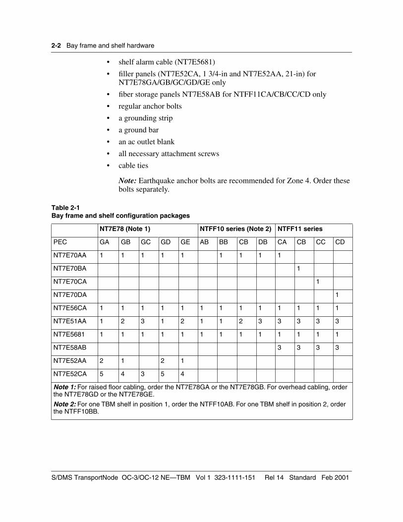
Table 2-1Bay frame and shelf configuration packages
NT7E78 (Note 1) NTFF10 series (Note 2) NTFF11 series
PEC GA GB GC GD GE AB BB CB DB CA CB CC CD
NT7E70AA 1 1 1 1 1 1 1 1 1
NT7E70BA 1
NT7E70CA 1
NT7E70DA 1
NT7E56CA 1 1 1 1 1 1 1 1 1 1 1 1 1
NT7E51AA 1 2 3 1 2 1 1 2 3 3 3 3 3
NT7E5681 1 1 1 1 1 1 1 1 1 1 1 1 1
NT7E58AB 3 3 3 3
NT7E52AA 2 1 2 1
NT7E52CA 5 4 3 5 4
Note 1: For raised floor cabling, order the NT7E78GA or the NT7E78GB. For overhead cabling, order the NT7E78GD or the NT7E78GE.
Note 2: For one TBM shelf in position 1, order the NTFF10AB. For one TBM shelf in position 2, order the NTFF10BB.
S/DMS TransportNode OC-3/OC-12 NE—TBM Vol 1 323-1111-151 Rel 14 Standard Feb 2001
Bay frame and shelf hardware
2-3
Ordering equipment separatelyFor individual components for an OC-3/OC-12 bay, order the following:
• one breaker interface panel (BIP)
• one, two or three TBM shelf and cooling COP kits (NT7E51AA), transport common equipment shelves (NT4K19AB), or enhanced transport common equipment shelves (NT4K19AC)
• enhanced through-flow cooling units if ordering the transport common equipment shelf (NT4K19AB) or the enhanced transport common equipment shelf (NT4K19AC)
• shelf alarm cables
• filler panels, fiber storage panel, fiber management tray or fiber splice trays, as required
• a spare fan module for each type of cooling unit
• one air filter if ordering the transport common equipment shelf (NT4K19AB) or the enhanced transport common equipment shelf (NT4K19AC)
• an ac outlet box for Underwriters Laboratories (UL) or Canadian Standards Association (CSA) applications, as required
• installation kit, as required
• frame junction kit or FiberWorld frame junction kit, as required
• frame extender, end guard or end guard extender, as required
• BIP modem, battery filter installation kit, or BIP panel filter kit, as required
Note: The TBM shelf and cooling COP kit (NT7E51AA) replaces the transport common equipment shelf (NT4K19AB), the enhanced transport common equipment shelf (NT4K19AC), and the through-flow cooling unit (NT4K18BA). These items will be manufacturer discontinued in the future.
See the following sections for a description of components. See Table 2-2 for ordering codes.
Bay framesA bay frame which houses up to three network elements includes the following components:
• a bay frame
• regular anchor bolts
• a grounding strip
• a ground bar
• an ac outlet blank
Ordering Information 323-1111-151 Rel 14 Standard Feb 2001
2-4
Bay frame and shelf hardware
• all necessary attachment screws
Note: Earthquake anchor bolts are recommended for Zone 4. Order these bolts separately.
Bay frames are 658 mm (26 in.) wide and 305 mm (12 in.) deep. Front and rear access bay frames are available in six different heights:
• 2.13 m (7 ft)
• 2.29 m (7.5 ft)
• 2.44 m (8 ft)
• 2.65 m (8.7 ft)
• 2.74 m (9 ft)
• 3.51 m (11.5 ft)
TBM shelvesOne shelf is required for each
• OC-12 terminal, regenerator, ADM, or ring ADM
• each OC-3 terminal or ADM
• each TBM control shelf
The TBM shelf and cooling COP kit (NT7E51AA) replaces
• the transport common equipment shelf (NT4K19AB)
• the enhanced common equipment shelf (NT4K19AC)
• the through-flow cooling unit (NT4K18BA).
The transport common equipment shelf (NT4K19AB) and the through-flow cooling unit (NT4K18BA) are manufacturer discontinued.
For more information on the TBM shelf and cooling COP kit (NT7E51AA), see the description on page 2-1.
Adding the TBM shelf and cooling COP kit (NT7E51AA) to existing baysThe TBM shelf and cooling COP kit (NT7E51AA) can be added to TBM single-shelf and TBM two-shelf bay configurations. The NT7E51AA shelf cannot be integrated into existing three-shelf bay configurations.
Only one additional NT7E51AA shelf can be installed in the NT7E78DA TBM configuration (single-shelf enhanced 2.13 m with raised floor cabling) because the through-flow cooling unit (NT4K18BA) takes up four mounting spaces.
S/DMS TransportNode OC-3/OC-12 NE—TBM Vol 1 323-1111-151 Rel 14 Standard Feb 2001
Bay frame and shelf hardware 2-5
The NT7E51AA shelf can be installed only in position 3, in the NT7E78DD TBM configuration (single-shelf enhanced 2.13 m with overhead cabling). In position 1, the shelf obstructs the air flow of the cooling unit because of the louver air control design of the shelf. Remove filler panel NT7E52CA and move the colling unit, TBM shelf, and air filter up one mounting space to make room for the TBM shelf and cooling COP kit.
Order one spare air filter (NPS50004-06) and one spare fan module (NT7E55AA) for the TBM shelf and cooling COP kit (NT7E51AA).
TBM power termination kit, cable adapter, and power cable assemblyTo add a TBM shelf and cooling COP kit (NT7E51AA) to a bay equipped with an NT7E56AA BIP, order one NT4K1950 TBM power termination kit for each NT7E51AA kit (use the NT4K1950 kit instead of the NT4K1951 kit which comes with the TBM shelf and cooling COP kit). Order one TBM power cable assembly (NT7E5659) for each bay.
The NT4K1951 TBM power cable adapter is included with each transport common equipment shelf (NT4K19AB and NT4K19AA), to connect the shelf and the NT7E56BA or NT7E56CA BIP. To add a shelf to a bay equipped with an NT7E56AA BIP, order one NT4K1950 TBM power termination kit to connect the shelf and the NT7E56AA BIP.
Cooling units and accessoriesThe TBM cooling unit kit (NT4K11AB) and the TBM cooling unit kit with no air filter (NT4K11BA) contain the following:
• one through-flow cooling unit (NT4K18BA)
• three fan modules for the through-flow cooling unit (NT4K17BA)
• one interface cable
• one filler LCAP
• miscellaneous hardware
The TBM cooling unit kit (NT4K11AB) also contains one air filter (NT4K15CA) to be mounted below the cooling unit or the lowest TBM shelf.
Upgrading to VTMOrder the TBM cooling unit kit (NT4K11AB) and one CAP upgrade procedure NTR771CG for each site for one shelf equipped in the top position. Install the air filter below the NT4K18BA cooling shelf.
Order the TBM cooling unit kit with no air filter (NT4K11BA) and one CAP upgrade procedure NTR771CG for each site for the following configurations:
• one shelf equipped in the second position
• two-shelf configuration
Ordering Information 323-1111-151 Rel 14 Standard Feb 2001
2-6 Bay frame and shelf hardware
• three-shelf configuration
Note: For the three-shelf configuration, order also one COP cooling unit upgrade kit for each bay (NT4K19AS), one COP cooling unit installers kit (NT4K19AR) for each site, and one CAP upgrade procedure NTR770CG for each site.
Spare cooling modulesOrder spare cooling modules as follows:
• NT4K17AA cooling module for the NT4K18AA cooling unit (one for each site)
• NT4K17BA through-flow cooling unit fan module for the NT4K18BA through-flow cooling unit (one for each site)
• one NT4K19AT COP cooling unit maintenance kit for each site for the NT4K19AC (three-shelf applications only)
• NT4K19AR cooling unit installation kit for the NT4K19AC (three-shelf applications) (kit contents are re-usable, and required for maintenance and installation)
The through-flow cooling unit (NT4K18BA) and the through-flow cooling unit fan module (NT4K17BA) are not interchangeable with the cooling unit (NT4K18AA) and the cooling unit fan module (NT4K17AA).
For the enhanced three-shelf configuration using the TBM shelf equipped with a COP cooling unit in position 3 (NT4K19AC), order one spare NT4K19AT COP cooling unit for each site.
Note: For the TBM shelf and cooling COP kit (NT7E51AA), the cooling unit is integrated into the shelf and is not ordered separately.
COP cooling unit maintenance kitThe COP cooling unit maintenance kit includes a temporary thermal duct, a COP cooling unit without an LCAP, and two temporary ground bars. Order as required to replace defective COP cooling units. A COP cooling unit installation kit (NT4K19AR) is also required for maintenance. The items in this kit are re-usable.
Cooling unit interface termination plugIf more than one TBM shelf is installed in the bay, the cooling unit interface connector on the SIL remains unconnected. Terminate the connector with a cooling unit interface termination plug (NT4K85JB).
Fan modulesOrder three fan modules for each cooling unit NT4K18AA or NT4K18BA. Order one spare fan module for each type of cooling unit (NT4K18AA or NT4K18BA) for each site.
S/DMS TransportNode OC-3/OC-12 NE—TBM Vol 1 323-1111-151 Rel 14 Standard Feb 2001
Bay frame and shelf hardware 2-7
Order one spare fan module (NT7E55AA) for the TBM shelf and cooling COP kit (NT7E51AA) for each site.
For the enhanced three-shelf configuration using the TBM shelf equipped with a COP cooling unit in position 3 (NT4K19AC), order one spare NT4K19AT COP cooling unit for each site. For the three-shelf configuration, ensure one re-usable NT4K19AR installation kit is available for the in-service upgrade of an NT4K19AB shelf to an NT4K19AC shelf.
Ordering spares for VTM upgradesFor one- and two-shelf configurations, order one spare fan module for the through-flow cooling unit (NT4K17BA) for each site.
For three-shelf configurations, order one spare fan module for the through-flow cooling unit (NT4K17BA) for each site. Order one spare COP cooling unit maintenance kit (NT4K19AT) for each site.
Air filtersOrder one air filter unit for each bay; the NT4K15CA is equipped directly below the cooling unit, or below the bottom TBM shelf (if equipped). For existing bays equipped with NT4K11AA cooling unit kits which are not being replaced for VTM applications, order the NT4K15CA air filter with the first NT4K19AB shelf mounted below the cooling unit. For an enhanced bay, the air filter is included in the NT4K11AB cooling unit kit.
Order at least one spare air filter (NPS50004-06) or six (NT7E6065)for the TBM shelf and cooling COP kit (NT7E51AA) for each site. Order at lease one spare air filter (NTS5004-08) for each NT4K15AA or NT4K15CA air filter unit.
Other bay and shelf accessoriesBreaker interface panels and battery filter installation kitsEach bay requires one breaker interface panel (BIP). To upgrade the manufacturer discontinued BIP NT7E56AA to an NT7E56AB, order the breaker interface panel conversion kit (NT7E6035). The kit consists of the following:
• breaker interface display assembly (NT7E5604)
• a BIP identification label
• eight lamps
For a BIP with an integral modem, order a battery filter installation kit (NT7E6032) to complete the conversion. For a BIP with no integral modem, order the breaker interface panel filter kit (NT7E6060).
Ordering Information 323-1111-151 Rel 14 Standard Feb 2001
2-8 Bay frame and shelf hardware
BIP modem (2400-baud)For the convenience of a built-in modem, order one 2400-baud BIP modem for each BIP. Also, order the appropriate BIP modem cable (see Table 4-12, “Miscellaneous cables” on page 4-16).
BIP lampOrder 6-V lamps for the breaker interface panel NT7E56BA or NT7E56AB, or 28-V lamps for the NT7E56AA (manufacturer discontinued).
BIP display assemblyThe breaker interface display assembly has the associated sub-miniature lamps mounted on the circuit board.
Ac outlet boxOrder an ac outlet box for Underwriters Laboratories (UL) or Canadian Standards Association (CSA) applications as required.
Circuit breaker and BIP fuseOrder the kits as a spare or extra unit for field replacements.
Fiber storage panel or fiber management storage trayUse fiber storage panels to store excess fiber for patchcords. As a general rule, if the bay has only one or two shelves, order one or two NT7E58AB fiber storage panels. If the bay has two or three shelves, order a fiber management storage tray.
Order the NT7E58AC fiber management storage tray for bays with a high density of cable fibers (more than four fibers in a tray). The tray holds a maximum of 20 fibers, 10 of which can have miniature variable-optical attenuators (mVOA). As a general rule, order the fiber management storage tray if the bay has two or three shelves.
Fiber splice trayOrder one or two fiber splice trays for each bay. The fiber splice tray houses two organizer trays, each of which provides a splice location for up to 12 fibers.
Note: You cannot use the fiber splice tray to terminate outside plant fiber cable.
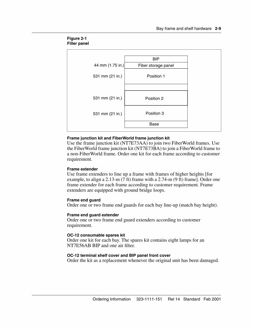
Filler panelOrder filler panels 44 mm (1.75 in.) and 531 mm (21 in.) as follows:
• Use the 44-mm filler panel (1.75 in.) if no fiber storage panel is required.
• Use 531-mm filler panels (21 in.) in positions 1, 2, and 3 when TBM shelves are not equipped (see Figure 2-1). A maximum of three TBM shelves can be equipped for each bay (see Figure 2-1).
S/DMS TransportNode OC-3/OC-12 NE—TBM Vol 1 323-1111-151 Rel 14 Standard Feb 2001
Bay frame and shelf hardware 2-9
Figure 2-1Filler panel
Frame junction kit and FiberWorld frame junction kitUse the frame junction kit (NT7E73AA) to join two FiberWorld frames. Use the FiberWorld frame junction kit (NT7E73BA) to join a FiberWorld frame to a non-FiberWorld frame. Order one kit for each frame according to customer requirement.
Frame extenderUse frame extenders to line up a frame with frames of higher heights [for example, to align a 2.13-m (7 ft) frame with a 2.74-m (9 ft) frame]. Order one frame extender for each frame according to customer requirement. Frame extenders are equipped with ground bridge loops.
Frame end guardOrder one or two frame end guards for each bay line-up (match bay height).
Frame end guard extenderOrder one or two frame end guard extenders according to customer requirement.
OC-12 consumable spares kitOrder one kit for each bay. The spares kit contains eight lamps for an NT7E56AB BIP and one air filter.
OC-12 terminal shelf cover and BIP panel front coverOrder the kit as a replacement whenever the original unit has been damaged.
Position 1
Position 2
Fiber storage panel
Position 3
Base
531 mm (21 in.)
531 mm (21 in.)
531 mm (21 in.)
BIP
44 mm (1.75 in.)
Ordering Information 323-1111-151 Rel 14 Standard Feb 2001
2-10 Bay frame and shelf hardware
TBM shelf installation kitOrder one installation kit for each OC-3/OC-12 shelf. The installation kit contains the mounting bolts to install the Transport Bandwidth Manager (TBM) shelf onto the frame, and the DS3 cable supports to ensure that the minimum bending radius is not exceeded.
Individual circuit packsUse circuit packs to add DS1, DS3, STS-1, or OC-3 channels to an existing transport channel at a terminal, ADM, or ring ADM site, subject to bandwidth and shelf layout limitations. Order individual circuit packs as field replaceable units or as optional equipment. See “Circuit packs” on page 3-1.
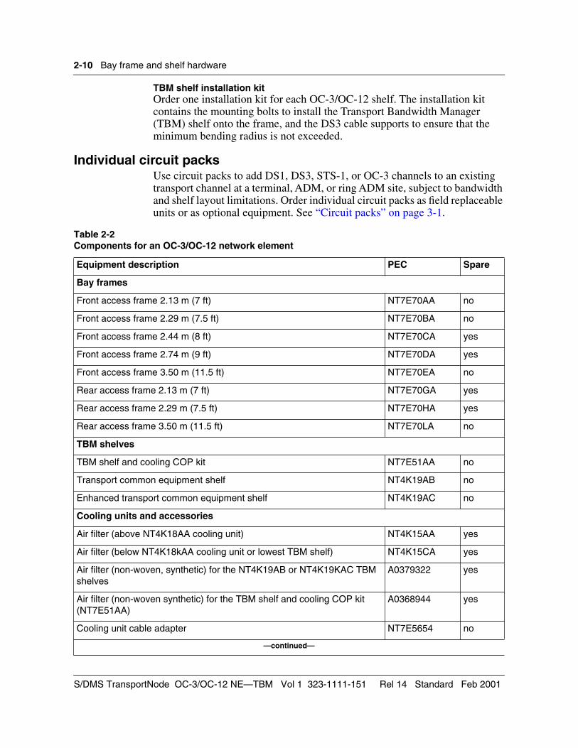
Table 2-2 Components for an OC-3/OC-12 network element
Equipment description PEC Spare
Bay frames
Front access frame 2.13 m (7 ft) NT7E70AA no
Front access frame 2.29 m (7.5 ft) NT7E70BA no
Front access frame 2.44 m (8 ft) NT7E70CA yes
Front access frame 2.74 m (9 ft) NT7E70DA yes
Front access frame 3.50 m (11.5 ft) NT7E70EA no
Rear access frame 2.13 m (7 ft) NT7E70GA yes
Rear access frame 2.29 m (7.5 ft) NT7E70HA yes
Rear access frame 3.50 m (11.5 ft) NT7E70LA no
TBM shelves
TBM shelf and cooling COP kit NT7E51AA no
Transport common equipment shelf NT4K19AB no
Enhanced transport common equipment shelf NT4K19AC no
Cooling units and accessories
Air filter (above NT4K18AA cooling unit) NT4K15AA yes
Air filter (below NT4K18kAA cooling unit or lowest TBM shelf) NT4K15CA yes
Air filter (non-woven, synthetic) for the NT4K19AB or NT4K19KAC TBM shelves
A0379322 yes
Air filter (non-woven synthetic) for the TBM shelf and cooling COP kit (NT7E51AA)
A0368944 yes
Cooling unit cable adapter NT7E5654 no
—continued—
S/DMS TransportNode OC-3/OC-12 NE—TBM Vol 1 323-1111-151 Rel 14 Standard Feb 2001
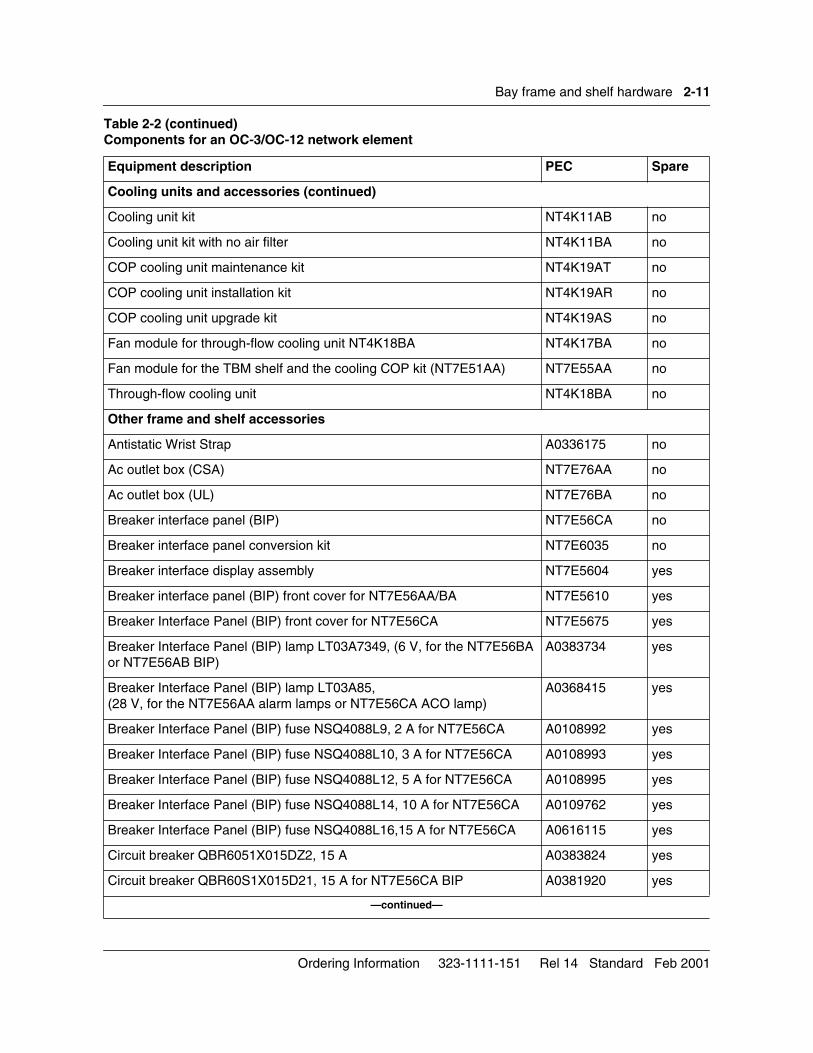
Bay frame and shelf hardware 2-11
Cooling units and accessories (continued)
Cooling unit kit NT4K11AB no
Cooling unit kit with no air filter NT4K11BA no
COP cooling unit maintenance kit NT4K19AT no
COP cooling unit installation kit NT4K19AR no
COP cooling unit upgrade kit NT4K19AS no
Fan module for through-flow cooling unit NT4K18BA NT4K17BA no
Fan module for the TBM shelf and the cooling COP kit (NT7E51AA) NT7E55AA no
Through-flow cooling unit NT4K18BA no
Other frame and shelf accessories
Antistatic Wrist Strap A0336175 no
Ac outlet box (CSA) NT7E76AA no
Ac outlet box (UL) NT7E76BA no
Breaker interface panel (BIP) NT7E56CA no
Breaker interface panel conversion kit NT7E6035 no
Breaker interface display assembly NT7E5604 yes
Breaker interface panel (BIP) front cover for NT7E56AA/BA NT7E5610 yes
Breaker Interface Panel (BIP) front cover for NT7E56CA NT7E5675 yes
Breaker Interface Panel (BIP) lamp LT03A7349, (6 V, for the NT7E56BA or NT7E56AB BIP)
A0383734 yes
Breaker Interface Panel (BIP) lamp LT03A85,(28 V, for the NT7E56AA alarm lamps or NT7E56CA ACO lamp)
A0368415 yes
Breaker Interface Panel (BIP) fuse NSQ4088L9, 2 A for NT7E56CA A0108992 yes
Breaker Interface Panel (BIP) fuse NSQ4088L10, 3 A for NT7E56CA A0108993 yes
Breaker Interface Panel (BIP) fuse NSQ4088L12, 5 A for NT7E56CA A0108995 yes
Breaker Interface Panel (BIP) fuse NSQ4088L14, 10 A for NT7E56CA A0109762 yes
Breaker Interface Panel (BIP) fuse NSQ4088L16,15 A for NT7E56CA A0616115 yes
Circuit breaker QBR6051X015DZ2, 15 A A0383824 yes
Circuit breaker QBR60S1X015D21, 15 A for NT7E56CA BIP A0381920 yes
—continued—
Table 2-2 (continued)Components for an OC-3/OC-12 network element
Equipment description PEC Spare
Ordering Information 323-1111-151 Rel 14 Standard Feb 2001
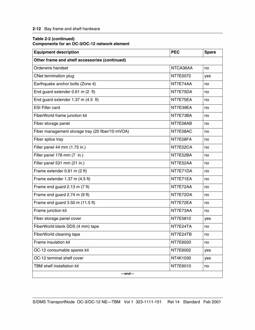
2-12 Bay frame and shelf hardware
Other frame and shelf accessories (continued)
Orderwire handset NTCA36AA no
CNet termination plug NT7E5072 yes
Earthquake anchor bolts (Zone 4) NT7E74AA no
End guard extender 0.61 m (2 ft) NT7E75DA no
End guard extender 1.37 m (4.5 ft) NT7E75EA no
ESI Filler card NT7E39EA no
FiberWorld frame junction kit NT7E73BA no
Fiber storage panel NT7E58AB no
Fiber management storage tray (20 fiber/10 mVOA) NT7E58AC no
Fiber splice tray NT7E58FA no
Filler panel 44 mm (1.75 in.) NT7E52CA no
Filler panel 178 mm (7 in.) NT7E52BA no
Filler panel 531 mm (21 in.) NT7E52AA no
Frame extender 0.61 m (2 ft) NT7E71DA no
Frame extender 1.37 m (4.5 ft) NT7E71EA no
Frame end guard 2.13 m (7 ft) NT7E72AA no
Frame end guard 2.74 m (9 ft) NT7E72DA no
Frame end guard 3.50 m (11.5 ft) NT7E72EA no
Frame junction kit NT7E73AA no
Fiber storage panel cover NT7E5810 yes
FiberWorld blank DDS (4 mm) tape NT7E24TA no
FiberWorld cleaning tape NT7E24TB no
Frame insulation kit NT7E6020 no
OC-12 consumable spares kit NT7E6002 yes
OC-12 terminal shelf cover NT4K1030 yes
TBM shelf installation kit NT7E6010 no
—end—
Table 2-2 (continued)Components for an OC-3/OC-12 network element
Equipment description PEC Spare
S/DMS TransportNode OC-3/OC-12 NE—TBM Vol 1 323-1111-151 Rel 14 Standard Feb 2001
3-1
Circuit packs 3-This chapter describes how to order circuit packs for an OC-3 or OC-12 network element. The equipment is identified by a product engineering code (PEC).
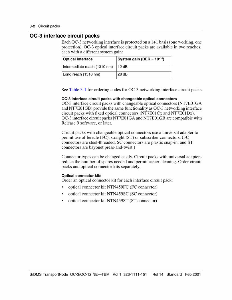
Transport Bandwidth ManagementThe number, type, and location of transport interface circuit packs depends on the TBM shelf application:
• A terminal shelf houses two bidirectional transport interface circuit packs in slots 9 and 10 (one working and one protection).
• A linear add-drop multiplexer (ADM) shelf houses four bidirectional transport interface circuit packs in slots 5, 7, 9, and 10 (two working and two protection).
• A network (NWK) ring ADM shelf houses two transport interface circuit packs (NT7E02) in slots 5 and 9, and two ring loopback circuit packs in slots 7 and 10.
• A VTM ring ADM shelf houses two transport interface circuit packs (NT7E05) in slots 9 and 10.
• A regenerator shelf houses two bidirectional transport interface circuit packs in slots 5 and 9.
Each OC-3 and OC-12 shelf supports a wide range of DS1, DS3, STS-1, and OC-3 tributary configuration options. For more information, see System Description, 323-1111-100.
See Table 3-1 to Table 3-6 for circuit pack ordering codes.
Ordering Information 323-1111-151 Rel 14 Standard Feb 2001
3-2 Circuit packs
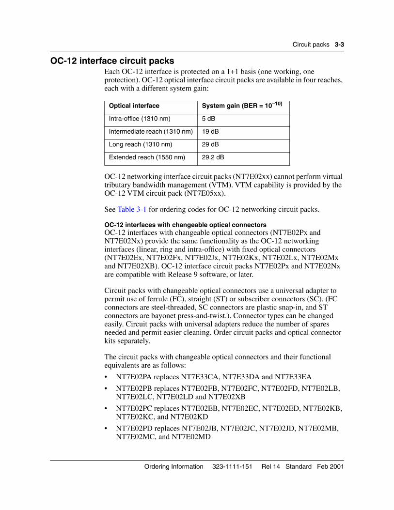
OC-3 interface circuit packsEach OC-3 networking interface is protected on a 1+1 basis (one working, one protection). OC-3 optical interface circuit packs are available in two reaches, each with a different system gain:
See Table 3-1 for ordering codes for OC-3 networking interface circuit packs.
OC-3 interface circuit packs with changeable optical connectorsOC-3 interface circuit packs with changeable optical connectors (NT7E01GA and NT7E01GB) provide the same functionality as OC-3 networking interface circuit packs with fixed optical connectors (NT7E01Cx and NT7E01Dx). OC-3 interface circuit packs NT7E01GA and NT7E01GB are compatible with Release 9 software, or later.
Circuit packs with changeable optical connectors use a universal adapter to permit use of ferrule (FC), straight (ST) or subscriber connectors. (FC connectors are steel-threaded, SC connectors are plastic snap-in, and ST connectors are bayonet press-and-twist.)
Connector types can be changed easily. Circuit packs with universal adapters reduce the number of spares needed and permit easier cleaning. Order circuit packs and optical connector kits separately.
Optical connector kitsOrder an optical connector kit for each interface circuit pack:
• optical connector kit NTN459FC (FC connector)
• optical connector kit NTN459SC (SC connector)
• optical connector kit NTN459ST (ST connector)
Optical interface System gain (BER = 10–10)
Intermediate reach (1310 nm) 12 dB
Long reach (1310 nm) 28 dB
S/DMS TransportNode OC-3/OC-12 NE—TBM Vol 1 323-1111-151 Rel 14 Standard Feb 2001
Circuit packs 3-3
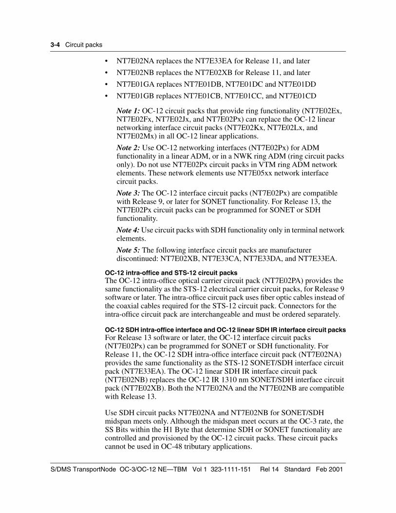
OC-12 interface circuit packsEach OC-12 interface is protected on a 1+1 basis (one working, one protection). OC-12 optical interface circuit packs are available in four reaches, each with a different system gain:
OC-12 networking interface circuit packs (NT7E02xx) cannot perform virtual tributary bandwidth management (VTM). VTM capability is provided by the OC-12 VTM circuit pack (NT7E05xx).
See Table 3-1 for ordering codes for OC-12 networking circuit packs.
OC-12 interfaces with changeable optical connectorsOC-12 interfaces with changeable optical connectors (NT7E02Px and NT7E02Nx) provide the same functionality as the OC-12 networking interfaces (linear, ring and intra-office) with fixed optical connectors (NT7E02Ex, NT7E02Fx, NT7E02Jx, NT7E02Kx, NT7E02Lx, NT7E02Mx and NT7E02XB). OC-12 interface circuit packs NT7E02Px and NT7E02Nx are compatible with Release 9 software, or later.
Circuit packs with changeable optical connectors use a universal adapter to permit use of ferrule (FC), straight (ST) or subscriber connectors (SC). (FC connectors are steel-threaded, SC connectors are plastic snap-in, and ST connectors are bayonet press-and-twist.). Connector types can be changed easily. Circuit packs with universal adapters reduce the number of spares needed and permit easier cleaning. Order circuit packs and optical connector kits separately.
The circuit packs with changeable optical connectors and their functional equivalents are as follows:
• NT7E02PA replaces NT7E33CA, NT7E33DA and NT7E33EA
• NT7E02PB replaces NT7E02FB, NT7E02FC, NT7E02FD, NT7E02LB, NT7E02LC, NT7E02LD and NT7E02XB
• NT7E02PC replaces NT7E02EB, NT7E02EC, NT7E02ED, NT7E02KB, NT7E02KC, and NT7E02KD
• NT7E02PD replaces NT7E02JB, NT7E02JC, NT7E02JD, NT7E02MB, NT7E02MC, and NT7E02MD
Optical interface System gain (BER = 10–10)
Intra-office (1310 nm) 5 dB
Intermediate reach (1310 nm) 19 dB
Long reach (1310 nm) 29 dB
Extended reach (1550 nm) 29.2 dB
Ordering Information 323-1111-151 Rel 14 Standard Feb 2001
3-4 Circuit packs
• NT7E02NA replaces the NT7E33EA for Release 11, and later
• NT7E02NB replaces the NT7E02XB for Release 11, and later
• NT7E01GA replaces NT7E01DB, NT7E01DC and NT7E01DD
• NT7E01GB replaces NT7E01CB, NT7E01CC, and NT7E01CD
Note 1: OC-12 circuit packs that provide ring functionality (NT7E02Ex, NT7E02Fx, NT7E02Jx, and NT7E02Px) can replace the OC-12 linear networking interface circuit packs (NT7E02Kx, NT7E02Lx, and NT7E02Mx) in all OC-12 linear applications.
Note 2: Use OC-12 networking interfaces (NT7E02Px) for ADM functionality in a linear ADM, or in a NWK ring ADM (ring circuit packs only). Do not use NT7E02Px circuit packs in VTM ring ADM network elements. These network elements use NT7E05xx network interface circuit packs.
Note 3: The OC-12 interface circuit packs (NT7E02Px) are compatible with Release 9, or later for SONET functionality. For Release 13, the NT7E02Px circuit packs can be programmed for SONET or SDH functionality.
Note 4: Use circuit packs with SDH functionality only in terminal network elements.
Note 5: The following interface circuit packs are manufacturer discontinued: NT7E02XB, NT7E33CA, NT7E33DA, and NT7E33EA.
OC-12 intra-office and STS-12 circuit packsThe OC-12 intra-office optical carrier circuit pack (NT7E02PA) provides the same functionality as the STS-12 electrical carrier circuit packs, for Release 9 software or later. The intra-office circuit pack uses fiber optic cables instead of the coaxial cables required for the STS-12 circuit pack. Connectors for the intra-office circuit pack are interchangeable and must be ordered separately.
OC-12 SDH intra-office interface and OC-12 linear SDH IR interface circuit packsFor Release 13 software or later, the OC-12 interface circuit packs (NT7E02Px) can be programmed for SONET or SDH functionality. For Release 11, the OC-12 SDH intra-office interface circuit pack (NT7E02NA) provides the same functionality as the STS-12 SONET/SDH interface circuit pack (NT7E33EA). The OC-12 linear SDH IR interface circuit pack (NT7E02NB) replaces the OC-12 IR 1310 nm SONET/SDH interface circuit pack (NT7E02XB). Both the NT7E02NA and the NT7E02NB are compatible with Release 13.
Use SDH circuit packs NT7E02NA and NT7E02NB for SONET/SDH midspan meets only. Although the midspan meet occurs at the OC-3 rate, the SS Bits within the H1 Byte that determine SDH or SONET functionality are controlled and provisioned by the OC-12 circuit packs. These circuit packs cannot be used in OC-48 tributary applications.
S/DMS TransportNode OC-3/OC-12 NE—TBM Vol 1 323-1111-151 Rel 14 Standard Feb 2001
Circuit packs 3-5
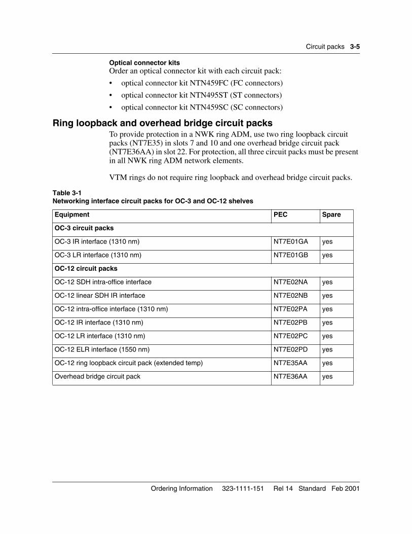
Optical connector kitsOrder an optical connector kit with each circuit pack:
• optical connector kit NTN459FC (FC connectors)
• optical connector kit NTN495ST (ST connectors)
• optical connector kit NTN459SC (SC connectors)
Ring loopback and overhead bridge circuit packsTo provide protection in a NWK ring ADM, use two ring loopback circuit packs (NT7E35) in slots 7 and 10 and one overhead bridge circuit pack (NT7E36AA) in slot 22. For protection, all three circuit packs must be present in all NWK ring ADM network elements.
VTM rings do not require ring loopback and overhead bridge circuit packs.
Table 3-1 Networking interface circuit packs for OC-3 and OC-12 shelves
Equipment PEC Spare
OC-3 circuit packs
OC-3 IR interface (1310 nm) NT7E01GA yes
OC-3 LR interface (1310 nm) NT7E01GB yes
OC-12 circuit packs
OC-12 SDH intra-office interface NT7E02NA yes
OC-12 linear SDH IR interface NT7E02NB yes
OC-12 intra-office interface (1310 nm) NT7E02PA yes
OC-12 IR interface (1310 nm) NT7E02PB yes
OC-12 LR interface (1310 nm) NT7E02PC yes
OC-12 ELR interface (1550 nm) NT7E02PD yes
OC-12 ring loopback circuit pack (extended temp) NT7E35AA yes
Overhead bridge circuit pack NT7E36AA yes
Ordering Information 323-1111-151 Rel 14 Standard Feb 2001
3-6 Circuit packs
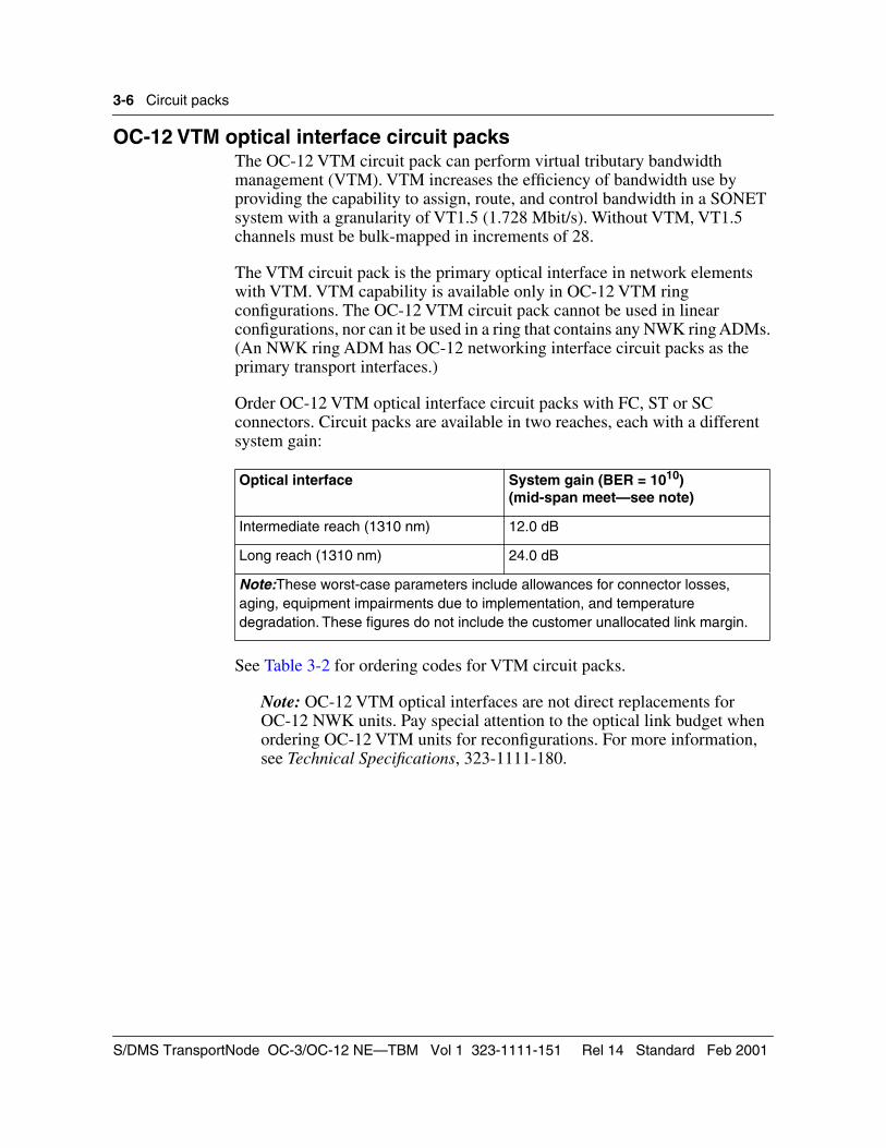
OC-12 VTM optical interface circuit packsThe OC-12 VTM circuit pack can perform virtual tributary bandwidth management (VTM). VTM increases the efficiency of bandwidth use by providing the capability to assign, route, and control bandwidth in a SONET system with a granularity of VT1.5 (1.728 Mbit/s). Without VTM, VT1.5 channels must be bulk-mapped in increments of 28.
The VTM circuit pack is the primary optical interface in network elements with VTM. VTM capability is available only in OC-12 VTM ring configurations. The OC-12 VTM circuit pack cannot be used in linear configurations, nor can it be used in a ring that contains any NWK ring ADMs. (An NWK ring ADM has OC-12 networking interface circuit packs as the primary transport interfaces.)
Order OC-12 VTM optical interface circuit packs with FC, ST or SC connectors. Circuit packs are available in two reaches, each with a different system gain:
See Table 3-2 for ordering codes for VTM circuit packs.
Note: OC-12 VTM optical interfaces are not direct replacements for OC-12 NWK units. Pay special attention to the optical link budget when ordering OC-12 VTM units for reconfigurations. For more information, see Technical Specifications, 323-1111-180.
Optical interface System gain (BER = 1010)(mid-span meet—see note)
Intermediate reach (1310 nm) 12.0 dB
Long reach (1310 nm) 24.0 dB
Note:These worst-case parameters include allowances for connector losses, aging, equipment impairments due to implementation, and temperature degradation. These figures do not include the customer unallocated link margin.
S/DMS TransportNode OC-3/OC-12 NE—TBM Vol 1 323-1111-151 Rel 14 Standard Feb 2001
Circuit packs 3-7
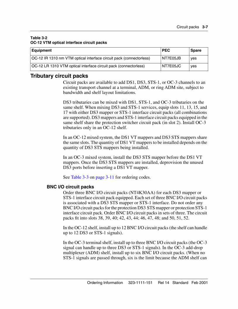
Tributary circuit packsCircuit packs are available to add DS1, DS3, STS-1, or OC-3 channels to an existing transport channel at a terminal, ADM, or ring ADM site, subject to bandwidth and shelf layout limitations.
DS3 tributaries can be mixed with DS1, STS-1, and OC-3 tributaries on the same shelf. When mixing DS3 and STS-1 services, equip slots 11, 13, 15, and 17 with either DS3 mapper or STS-1 interface circuit packs (all combinations are supported). DS3 mappers and STS-1 interface circuit packs equipped in the same shelf share the protection switcher circuit pack (in slot 2). Install OC-3 tributaries only in an OC-12 shelf.
In an OC-12 mixed system, the DS1 VT mappers and DS3 STS mappers share the same slots. The quantity of DS1 VT mappers to be installed depends on the quantity of DS3 STS mappers being installed.
In an OC-3 mixed system, install the DS3 STS mapper before the DS1 VT mappers. Once the DS3 STS mappers are installed, deprovision the unused DS3 ports before inserting a DS1 VT mapper.
See Table 3-3 on page 3-11 for ordering codes.
BNC I/O circuit packsOrder three BNC I/O circuit packs (NT4K30AA) for each DS3 mapper or STS-1 interface circuit pack equipped. Each set of three BNC I/O circuit packs is associated with a DS3 STS mapper or STS-1 interface. Do not order any BNC I/O circuit packs for the protection DS3 STS mapper or protection STS-1 interface circuit pack. Order BNC I/O circuit packs in sets of three. The circuit packs fit into slots 38, 39, 40; 42, 43, 44; 46, 47, 48; and 50, 51, 52.
In the OC-12 shelf, install up to 12 BNC I/O circuit packs (the shelf can handle up to 12 DS3 or STS-1 signals).
In the OC-3 terminal shelf, install up to three BNC I/O circuit packs (the OC-3 signal can handle up to three DS3 or STS-1 signals). In the OC-3 add-drop multiplexer (ADM) shelf, install up to six BNC I/O circuit packs. (When no STS-1 signals are passed through, six is the limit because the ADM shelf can
Table 3-2 OC-12 VTM optical interface circuit packs
Equipment PEC Spare
OC-12 IR 1310 nm VTM optical interface circuit pack (connectorless) NT7E05JB yes
OC-12 LR 1310 VTM optical interface circuit pack (connectorless) NT7E05JC yes
Ordering Information 323-1111-151 Rel 14 Standard Feb 2001
3-8 Circuit packs
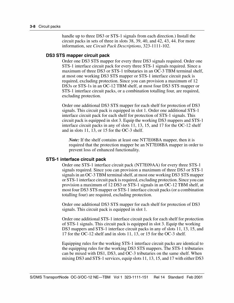
handle up to three DS3 or STS-1 signals from each direction.) Install the circuit packs in sets of three in slots 38, 39, 40, and 42, 43, 44. For more information, see Circuit Pack Descriptions, 323-1111-102.
DS3 STS mapper circuit packOrder one DS3 STS mapper for every three DS3 signals required. Order one STS-1 interface circuit pack for every three STS-1 signals required. Since a maximum of three DS3 or STS-1 tributaries in an OC-3 TBM terminal shelf, at most one working DS3 STS mapper or STS-1 interface circuit pack is required, excluding protection. Since you can provision a maximum of 12 DS3s or STS-1s in an OC-12 TBM shelf, at most four DS3 STS mapper or STS-1 interface circuit packs, or a combination totalling four, are required, excluding protection.
Order one additional DS3 STS mapper for each shelf for protection of DS3 signals. This circuit pack is equipped in slot 1. Order one additional STS-1 interface circuit pack for each shelf for protection of STS-1 signals. This circuit pack is equipped in slot 3. Equip the working DS3 mappers and STS-1 interface circuit packs in any of slots 11, 13, 15, and 17 for the OC-12 shelf and in slots 11, 13, or 15 for the OC-3 shelf.
Note: If the shelf contains at least one NT7E08BA mapper, then it is required that the protection mapper be an NT7E08BA mapper in order to prevent loss of enhanced functionality.
STS-1 interface circuit packOrder one STS-1 interface circuit pack (NT7E09AA) for every three STS-1 signals required. Since you can provision a maximum of three DS3 or STS-1 signals in an OC-3 TBM terminal shelf, at most one working DS3 STS mapper or STS-1 interface circuit pack is required, excluding protection. Since you can provision a maximum of 12 DS3 or STS-1 signals in an OC-12 TBM shelf, at most four DS3 STS mapper or STS-1 interface circuit packs (or a combination totalling four) are required, excluding protection.
Order one additional DS3 STS mapper for each shelf for protection of DS3 signals. This circuit pack is equipped in slot 1.
Order one additional STS-1 interface circuit pack for each shelf for protection of STS-1 signals. This circuit pack is equipped in slot 3. Equip the working DS3 mappers and STS-1 interface circuit packs in any of slots 11, 13, 15, and 17 for the OC-12 shelf and in slots 11, 13, or 15 for the OC-3 shelf.
Equipping rules for the working STS-1 interface circuit packs are identical to the equipping rules for the working DS3 STS mappers. The STS-1 tributaries can be mixed with DS1, DS3, and OC-3 tributaries on the same shelf. When mixing DS3 and STS-1 services, equip slots 11, 13, 15, and 17 with either DS3
S/DMS TransportNode OC-3/OC-12 NE—TBM Vol 1 323-1111-151 Rel 14 Standard Feb 2001
Circuit packs 3-9
mapper or STS-1 interface circuit packs (all combinations are supported). When a shelf is equipped with both DS3 mappers and STS-1 interface circuit packs, the protection switcher circuit pack (in slot 2) is shared by the services.
For more information on the shelf configurations, see System Description, 323-1111-100.
DS1 VT mapperIn an OC-12 shelf and an OC-3 ADM shelf, install up to 12 working DS1 VT synchronous mappers in slots 1 to 4, and 11 to 18. In an OC-3 terminal shelf, install up to six working DS1 VT synchronous mappers in slots 13 to 18. Install a protection DS1 VT synchronous mapper only in slot 19.
A pair of DS1 VT working mappers supplies the 28 VT1.5 signals (2 x 14 VT1.5 signals) required to fill the bandwidth of one STS-1. Install the working mappers in pairs of slots. In each pair of slots (for example, 17 and 18, 15 and 16, and 13 and 14), the mapper in the odd-numbered slot serves the first set of 14 VT1.5 signals (1 to 14), and the even-numbered slot serves the second set of 14 VT1.5 signals (15 to 28). In an OC-12 mixed system, DS1 VT mappers and DS3 STS mappers share the same slots. The quantity of DS1 VT mappers to be installed depends on the quantity of DS3 STS mappers being installed.
In an OC-3 mixed system, install DS1 VT mappers after DS3 STS mappers. Once DS3 STS mappers are installed, deprovision unused DS3 ports before inserting a DS1 VT mapper.
The DS1 VT mapper (NT7E04EA) maps up to 14 asynchronous or synchronous DS1 signals into VT1.5 signals as defined by the SONET standard. For OC-3 terminal nodes, provision a maximum of 84 DS1 signals (six DS1 VT mappers, excluding protection). For OC-3 ADM nodes, provision a maximum of 168 DS1 signals (12 DS1 VT mappers, excluding protection). Provision a maximum of 168 DS1 signals (12 DS1 VT mappers, excluding protection) at an OC-12 node.
Order one DS1 VT mapper for every 14 DS1 signals. One additional DS1 VT mapper for each shelf must be ordered for protection. The protection DS1 VT mapper is equipped in slot 19. The working mappers are equipped in slots 13 to 18 on OC-3 terminal shelves; and in slots 1 to 4, and 11 to 18 on OC-3 ADM shelves and OC-12 shelves.
When adding NT7E04EA DS1 mappers to a shelf, equip an NT7E04EA DS1 mapper in the protection slot (slot 19) before equipping any additional NT7E04EA mappers to ensure that the NT7E04CA mappers are protected.
Ordering Information 323-1111-151 Rel 14 Standard Feb 2001
3-10 Circuit packs
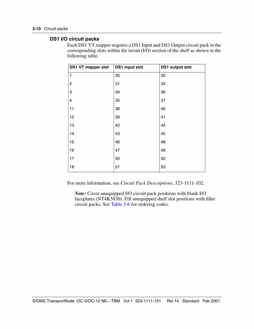
DS1 I/O circuit packsEach DS1 VT mapper requires a DS1 Input and DS1 Output circuit pack in the corresponding slots within the in/out (I/O) section of the shelf as shown in the following table.
For more information, see Circuit Pack Descriptions, 323-1111-102.
Note: Cover unequipped I/O circuit pack positions with blank I/O faceplates (NT4K5830). Fill unequipped shelf slot positions with filler circuit packs. See Table 3-6 for ordering codes.
DS1 VT mapper slot DS1 input slot DS1 output slot
1 30 32
2 31 33
3 34 36
4 35 37
11 38 40
12 39 41
13 42 44
14 43 45
15 46 48
16 47 49
17 50 52
18 51 53
S/DMS TransportNode OC-3/OC-12 NE—TBM Vol 1 323-1111-151 Rel 14 Standard Feb 2001
Circuit packs 3-11
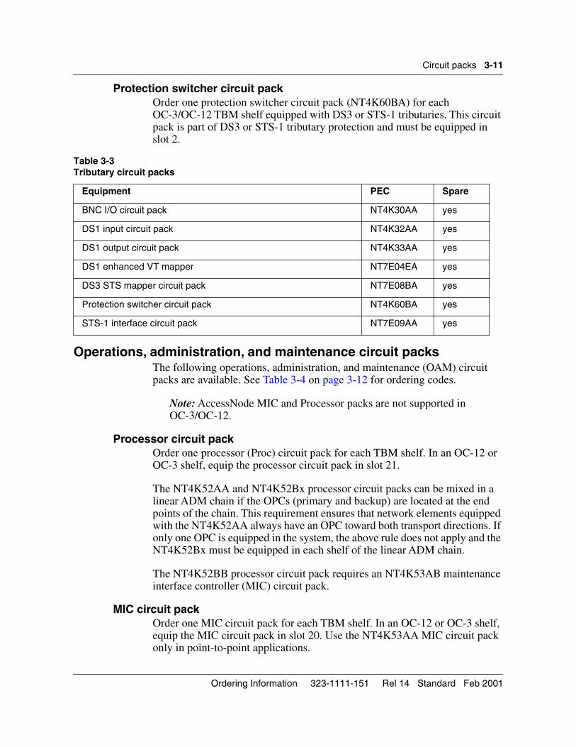
Protection switcher circuit packOrder one protection switcher circuit pack (NT4K60BA) for each OC-3/OC-12 TBM shelf equipped with DS3 or STS-1 tributaries. This circuit pack is part of DS3 or STS-1 tributary protection and must be equipped in slot 2.
Operations, administration, and maintenance circuit packsThe following operations, administration, and maintenance (OAM) circuit packs are available. See Table 3-4 on page 3-12 for ordering codes.
Note: AccessNode MIC and Processor packs are not supported in OC-3/OC-12.
Processor circuit packOrder one processor (Proc) circuit pack for each TBM shelf. In an OC-12 or OC-3 shelf, equip the processor circuit pack in slot 21.
The NT4K52AA and NT4K52Bx processor circuit packs can be mixed in a linear ADM chain if the OPCs (primary and backup) are located at the end points of the chain. This requirement ensures that network elements equipped with the NT4K52AA always have an OPC toward both transport directions. If only one OPC is equipped in the system, the above rule does not apply and the NT4K52Bx must be equipped in each shelf of the linear ADM chain.
The NT4K52BB processor circuit pack requires an NT4K53AB maintenance interface controller (MIC) circuit pack.
MIC circuit packOrder one MIC circuit pack for each TBM shelf. In an OC-12 or OC-3 shelf, equip the MIC circuit pack in slot 20. Use the NT4K53AA MIC circuit pack only in point-to-point applications.
Table 3-3 Tributary circuit packs
Equipment PEC Spare
BNC I/O circuit pack NT4K30AA yes
DS1 input circuit pack NT4K32AA yes
DS1 output circuit pack NT4K33AA yes
DS1 enhanced VT mapper NT7E04EA yes
DS3 STS mapper circuit pack NT7E08BA yes
Protection switcher circuit pack NT4K60BA yes
STS-1 interface circuit pack NT7E09AA yes
Ordering Information 323-1111-151 Rel 14 Standard Feb 2001
3-12 Circuit packs
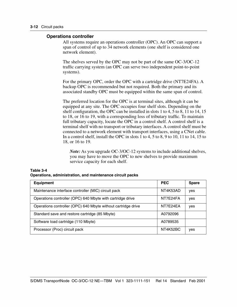
Operations controllerAll systems require an operations controller (OPC). An OPC can support a span of control of up to 34 network elements (one shelf is considered one network element).
The shelves served by the OPC may not be part of the same OC-3/OC-12 traffic carrying system (an OPC can serve two independent point-to-point systems).
For the primary OPC, order the OPC with a cartridge drive (NT7E24FA). A backup OPC is recommended but not required. Both the primary and its associated standby OPC must be equipped within the same span of control.
The preferred location for the OPC is at terminal sites, although it can be equipped at any site. The OPC occupies four shelf slots. Depending on the shelf configuration, the OPC can be installed in slots 1 to 4, 5 to 8, 11 to 14, 15 to 18, or 16 to 19, with a corresponding loss of tributary traffic. To maintain full tributary capacity, locate the OPC in a control shelf. A control shelf is a terminal shelf with no transport or tributary interfaces. A control shelf must be connected to a network element with transport interfaces, using a CNet cable. In a control shelf, install the OPC in slots 1 to 4, 5 to 8, 9 to 10, 11 to 14, 15 to 18, or 16 to 19.
Note: As you upgrade OC-3/OC-12 systems to include additional shelves, you may have to move the OPC to new shelves to provide maximum service capacity for each shelf.
Table 3-4Operations, administration, and maintenance circuit packs
Equipment PEC Spare
Maintenance interface controller (MIC) circuit pack NT4K53AD yes
Operations controller (OPC) 640 Mbyte with cartridge drive NT7E24FA yes
Operations controller (OPC) 640 Mbyte without cartridge drive NT7E24EA yes
Standard save and restore cartridge (85 Mbyte) A0792096
Software load cartridge (110 Mbyte) A0789535
Processor (Proc) circuit pack NT4K52BC yes
S/DMS TransportNode OC-3/OC-12 NE—TBM Vol 1 323-1111-151 Rel 14 Standard Feb 2001
Circuit packs 3-13
External synchronization interface circuit packsFor synchronous OC-3/OC-12 system operation, an external synchronization interface (ESI) carrier equipped with one (unprotected) or two (protected) ESI units is required in at least one line terminating equipment (LTE) for each system.
Synchronous operation is required for configurations such as rings, single-shelf ADM, and point-to-point linear systems transporting SONET tributaries (STS-1 or OC-3).
Synchronous operation is optional for OC-3/OC-12 point-to-point linear applications transporting asynchronous tributaries (DS1 or DS3).
For a synchronous point-to-point linear configuration, equip at least one of the two OC-3/OC-12 terminals with ESI. ESI circuit packs at the other terminal are optional. Use these circuit packs only to achieve timing externally through a building-integrated timing supply (BITS), or for timing distribution. Otherwise the second terminal can be looptimed without ESI circuit packs.
For configurations where the TBM shelf is used as a tributary shelf to the OC-48, ESI circuit packs are also optional. The TBM shelf can be either looptimed (no ESI required) or externally timed from a BITS (ESI required).
ESI circuit packs are required in all network elements used for timing distribution.
The NT7E27DA ESI circuit pack replaces the NT7E27BA ESI circuit pack. The NT7E27EA ESI circuit pack replaces the NT7E27CA ESI circuit pack. The replacement circuit packs are backward compatible with the circuit packs they replace.
The NT7E27DA and NT7E27EA circuit packs offer the following advantages:
• improved network performance through quicker detection and protection of ESI hardware failures and continuous operation during software upgrades
• lower operating costs due to the capability of ESI firmware upgrade (out-of-service upgrades only)
The NT7E27BA ESI unit offers enhanced detection of, and recovery from, timing deviations. Although the NT7E27BA unit is backwards compatible with the NT7E27AA unit, both ESI units must be NT7E27BA units and running on Release 8.10 software or earlier, for the enhanced feature to be operational.
Ordering Information 323-1111-151 Rel 14 Standard Feb 2001
3-14 Circuit packs
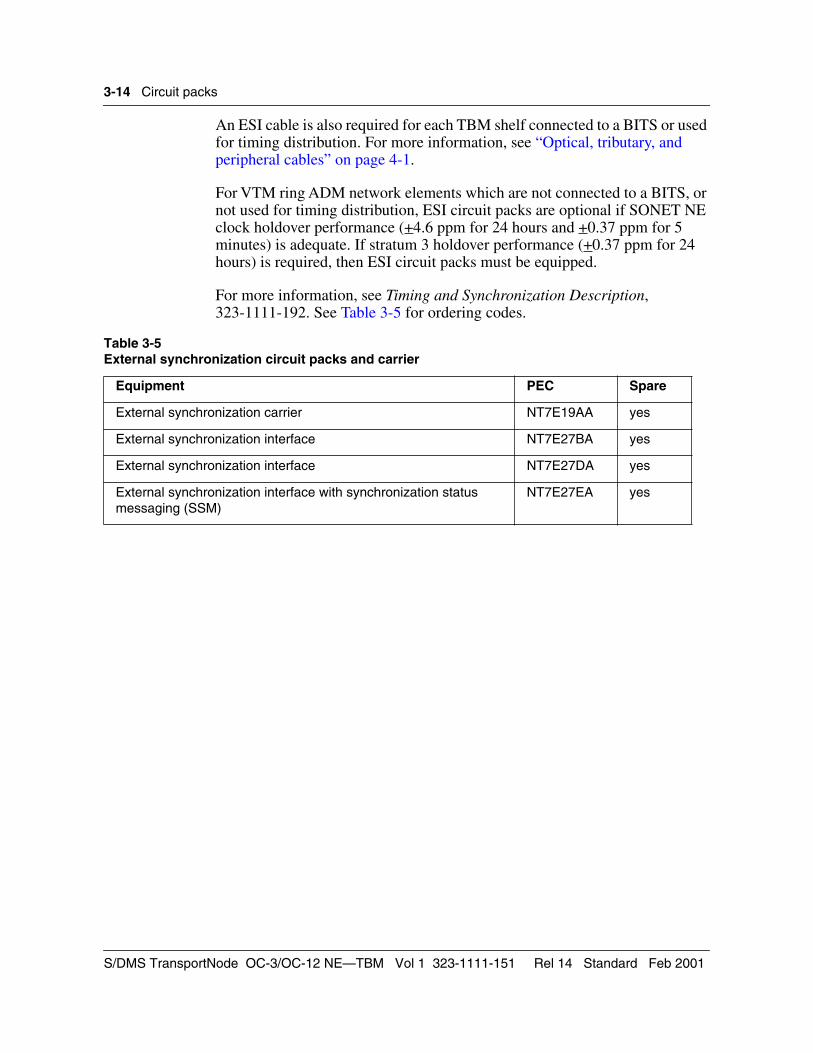
An ESI cable is also required for each TBM shelf connected to a BITS or used for timing distribution. For more information, see “Optical, tributary, and peripheral cables” on page 4-1.
For VTM ring ADM network elements which are not connected to a BITS, or not used for timing distribution, ESI circuit packs are optional if SONET NE clock holdover performance (+4.6 ppm for 24 hours and +0.37 ppm for 5 minutes) is adequate. If stratum 3 holdover performance (+0.37 ppm for 24 hours) is required, then ESI circuit packs must be equipped.
For more information, see Timing and Synchronization Description, 323-1111-192. See Table 3-5 for ordering codes.
Table 3-5External synchronization circuit packs and carrier
Equipment PEC Spare
External synchronization carrier NT7E19AA yes
External synchronization interface NT7E27BA yes
External synchronization interface NT7E27DA yes
External synchronization interface with synchronization status messaging (SSM)
NT7E27EA yes
S/DMS TransportNode OC-3/OC-12 NE—TBM Vol 1 323-1111-151 Rel 14 Standard Feb 2001
Circuit packs 3-15
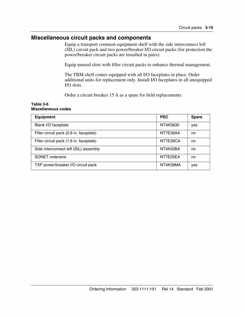
Miscellaneous circuit packs and componentsEquip a transport common equipment shelf with the side interconnect left (SIL) circuit pack and two power/breaker I/O circuit packs (for protection the power/breaker circuit packs are installed in pairs).
Equip unused slots with filler circuit packs to enhance thermal management.
The TBM shelf comes equipped with all I/O faceplates in place. Order additional units for replacement only. Install I/O faceplates in all unequipped I/O slots.
Order a circuit breaker 15 A as a spare for field replacements.
Table 3-6Miscellaneous codes
Equipment PEC Spare
Blank I/O faceplate NT4K5830 yes
Filler circuit pack (0.8 in. faceplate) NT7E39AA no
Filler circuit pack (1.6 in. faceplate) NT7E39CA no
Side interconnect left (SIL) assembly NT4K50BA no
SONET orderwire NT7E25EA no
TXP power/breaker I/O circuit pack NT4K58MA yes
Ordering Information 323-1111-151 Rel 14 Standard Feb 2001

3-16 Circuit packs
S/DMS TransportNode OC-3/OC-12 NE—TBM Vol 1 323-1111-151 Rel 14 Standard Feb 2001
4-1
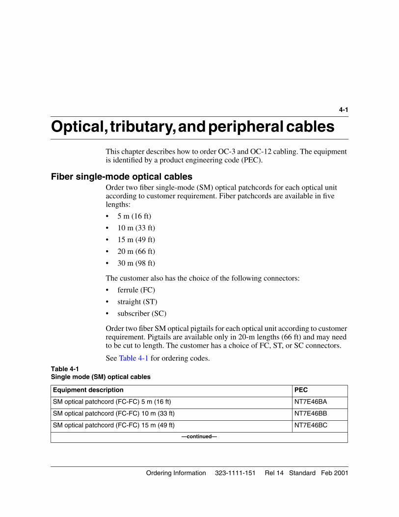
Optical, tributary, and peripheral cables4-This chapter describes how to order OC-3 and OC-12 cabling. The equipment is identified by a product engineering code (PEC).
Fiber single-mode optical cablesOrder two fiber single-mode (SM) optical patchcords for each optical unit according to customer requirement. Fiber patchcords are available in five lengths:
• 5 m (16 ft)
• 10 m (33 ft)
• 15 m (49 ft)
• 20 m (66 ft)
• 30 m (98 ft)
The customer also has the choice of the following connectors:
• ferrule (FC)
• straight (ST)
• subscriber (SC)
Order two fiber SM optical pigtails for each optical unit according to customer requirement. Pigtails are available only in 20-m lengths (66 ft) and may need to be cut to length. The customer has a choice of FC, ST, or SC connectors.
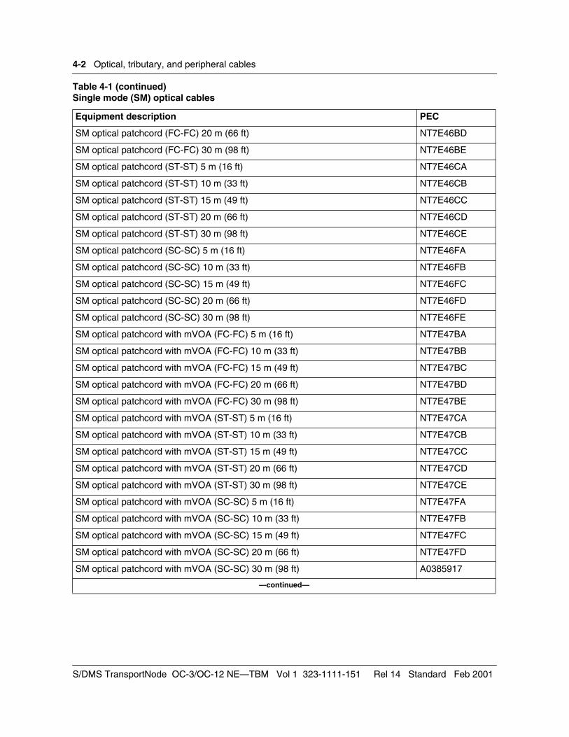
See Table 4-1 for ordering codes.Table 4-1 Single mode (SM) optical cables
Equipment description PEC
SM optical patchcord (FC-FC) 5 m (16 ft) NT7E46BA
SM optical patchcord (FC-FC) 10 m (33 ft) NT7E46BB
SM optical patchcord (FC-FC) 15 m (49 ft) NT7E46BC
—continued—
Ordering Information 323-1111-151 Rel 14 Standard Feb 2001
4-2 Optical, tributary, and peripheral cables
SM optical patchcord (FC-FC) 20 m (66 ft) NT7E46BD
SM optical patchcord (FC-FC) 30 m (98 ft) NT7E46BE
SM optical patchcord (ST-ST) 5 m (16 ft) NT7E46CA
SM optical patchcord (ST-ST) 10 m (33 ft) NT7E46CB
SM optical patchcord (ST-ST) 15 m (49 ft) NT7E46CC
SM optical patchcord (ST-ST) 20 m (66 ft) NT7E46CD
SM optical patchcord (ST-ST) 30 m (98 ft) NT7E46CE
SM optical patchcord (SC-SC) 5 m (16 ft) NT7E46FA
SM optical patchcord (SC-SC) 10 m (33 ft) NT7E46FB
SM optical patchcord (SC-SC) 15 m (49 ft) NT7E46FC
SM optical patchcord (SC-SC) 20 m (66 ft) NT7E46FD
SM optical patchcord (SC-SC) 30 m (98 ft) NT7E46FE
SM optical patchcord with mVOA (FC-FC) 5 m (16 ft) NT7E47BA
SM optical patchcord with mVOA (FC-FC) 10 m (33 ft) NT7E47BB
SM optical patchcord with mVOA (FC-FC) 15 m (49 ft) NT7E47BC
SM optical patchcord with mVOA (FC-FC) 20 m (66 ft) NT7E47BD
SM optical patchcord with mVOA (FC-FC) 30 m (98 ft) NT7E47BE
SM optical patchcord with mVOA (ST-ST) 5 m (16 ft) NT7E47CA
SM optical patchcord with mVOA (ST-ST) 10 m (33 ft) NT7E47CB
SM optical patchcord with mVOA (ST-ST) 15 m (49 ft) NT7E47CC
SM optical patchcord with mVOA (ST-ST) 20 m (66 ft) NT7E47CD
SM optical patchcord with mVOA (ST-ST) 30 m (98 ft) NT7E47CE
SM optical patchcord with mVOA (SC-SC) 5 m (16 ft) NT7E47FA
SM optical patchcord with mVOA (SC-SC) 10 m (33 ft) NT7E47FB
SM optical patchcord with mVOA (SC-SC) 15 m (49 ft) NT7E47FC
SM optical patchcord with mVOA (SC-SC) 20 m (66 ft) NT7E47FD
SM optical patchcord with mVOA (SC-SC) 30 m (98 ft) A0385917
—continued—
Table 4-1 (continued)Single mode (SM) optical cables
Equipment description PEC
S/DMS TransportNode OC-3/OC-12 NE—TBM Vol 1 323-1111-151 Rel 14 Standard Feb 2001
Optical, tributary, and peripheral cables 4-3
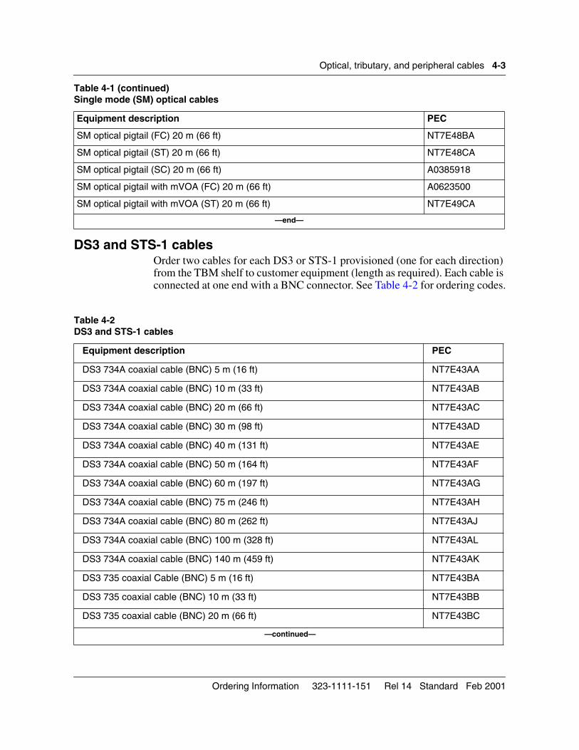
DS3 and STS-1 cablesOrder two cables for each DS3 or STS-1 provisioned (one for each direction) from the TBM shelf to customer equipment (length as required). Each cable is connected at one end with a BNC connector. See Table 4-2 for ordering codes.
SM optical pigtail (FC) 20 m (66 ft) NT7E48BA
SM optical pigtail (ST) 20 m (66 ft) NT7E48CA
SM optical pigtail (SC) 20 m (66 ft) A0385918
SM optical pigtail with mVOA (FC) 20 m (66 ft) A0623500
SM optical pigtail with mVOA (ST) 20 m (66 ft) NT7E49CA
—end—
Table 4-2 DS3 and STS-1 cables
Equipment description PEC
DS3 734A coaxial cable (BNC) 5 m (16 ft) NT7E43AA
DS3 734A coaxial cable (BNC) 10 m (33 ft) NT7E43AB
DS3 734A coaxial cable (BNC) 20 m (66 ft) NT7E43AC
DS3 734A coaxial cable (BNC) 30 m (98 ft) NT7E43AD
DS3 734A coaxial cable (BNC) 40 m (131 ft) NT7E43AE
DS3 734A coaxial cable (BNC) 50 m (164 ft) NT7E43AF
DS3 734A coaxial cable (BNC) 60 m (197 ft) NT7E43AG
DS3 734A coaxial cable (BNC) 75 m (246 ft) NT7E43AH
DS3 734A coaxial cable (BNC) 80 m (262 ft) NT7E43AJ
DS3 734A coaxial cable (BNC) 100 m (328 ft) NT7E43AL
DS3 734A coaxial cable (BNC) 140 m (459 ft) NT7E43AK
DS3 735 coaxial Cable (BNC) 5 m (16 ft) NT7E43BA
DS3 735 coaxial cable (BNC) 10 m (33 ft) NT7E43BB
DS3 735 coaxial cable (BNC) 20 m (66 ft) NT7E43BC
—continued—
Table 4-1 (continued)Single mode (SM) optical cables
Equipment description PEC
Ordering Information 323-1111-151 Rel 14 Standard Feb 2001
4-4 Optical, tributary, and peripheral cables
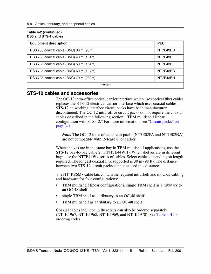
STS-12 cables and accessoriesThe OC-12 intra-office optical carrier interface which uses optical fiber cables replaces the STS-12 electrical carrier interface which uses coaxial cables. STS-12 networking interface circuit packs have been manufacturer discontinued. The OC-12 intra-office circuit packs do not require the coaxial cables described in the following section, “TBM multishelf linear configuration with STS-12.” For more information, see “Circuit packs” on page 3-1.
Note: The OC-12 intra-office circuit packs (NT7E02PA and NT7E02NA) are not compatible with Release 8, or earlier.
When shelves are in the same bay in TBM multishelf applications, use the STS-12 bay-to-bay cable 2 m (NT7E44WH). When shelves are in different bays, use the NT7E44Wx series of cables. Select cables depending on length required. The longest coaxial link supported is 30 m (98 ft). The distance between two STS-12 circuit packs cannot exceed this distance.
The NT4K86Mx cable kits contain the required intrashelf and intrabay cabling and hardware for four configurations:
• TBM multishelf linear configurations, single TBM shelf as a tributary to an OC-48 shelf
• single TBM shelf as a tributary to an OC-48 shelf
• TBM multishelf as a tributary to an OC-48 shelf
Coaxial cables included in these kits can also be ordered separately (NT4K1967, NT4K1968, NT4K1969, and NT4K1970). See Table 4-4 for ordering codes.
DS3 735 coaxial cable (BNC) 30 m (98 ft) NT7E43BD
DS3 735 coaxial cable (BNC) 40 m (131 ft) NT7E43BE
DS3 735 coaxial cable (BNC) 50 m (164 ft) NT7E43BF
DS3 735 coaxial cable (BNC) 60 m (197 ft) NT7E43BG
DS3 735 coaxial cable (BNC) 70 m (230 ft) NT7E43BH
—end—
Table 4-2 (continued)DS3 and STS-1 cables
Equipment description PEC
S/DMS TransportNode OC-3/OC-12 NE—TBM Vol 1 323-1111-151 Rel 14 Standard Feb 2001
Optical, tributary, and peripheral cables 4-5
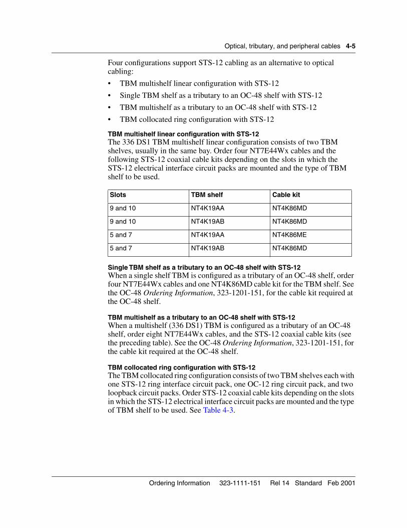
Four configurations support STS-12 cabling as an alternative to optical cabling:
• TBM multishelf linear configuration with STS-12
• Single TBM shelf as a tributary to an OC-48 shelf with STS-12
• TBM multishelf as a tributary to an OC-48 shelf with STS-12
• TBM collocated ring configuration with STS-12
TBM multishelf linear configuration with STS-12The 336 DS1 TBM multishelf linear configuration consists of two TBM shelves, usually in the same bay. Order four NT7E44Wx cables and the following STS-12 coaxial cable kits depending on the slots in which the STS-12 electrical interface circuit packs are mounted and the type of TBM shelf to be used.
Single TBM shelf as a tributary to an OC-48 shelf with STS-12When a single shelf TBM is configured as a tributary of an OC-48 shelf, order four NT7E44Wx cables and one NT4K86MD cable kit for the TBM shelf. See the OC-48 Ordering Information, 323-1201-151, for the cable kit required at the OC-48 shelf.
TBM multishelf as a tributary to an OC-48 shelf with STS-12When a multishelf (336 DS1) TBM is configured as a tributary of an OC-48 shelf, order eight NT7E44Wx cables, and the STS-12 coaxial cable kits (see the preceding table). See the OC-48 Ordering Information, 323-1201-151, for the cable kit required at the OC-48 shelf.
TBM collocated ring configuration with STS-12The TBM collocated ring configuration consists of two TBM shelves each with one STS-12 ring interface circuit pack, one OC-12 ring circuit pack, and two loopback circuit packs. Order STS-12 coaxial cable kits depending on the slots in which the STS-12 electrical interface circuit packs are mounted and the type of TBM shelf to be used. See Table 4-3.
Slots TBM shelf Cable kit
9 and 10 NT4K19AA NT4K86MD
9 and 10 NT4K19AB NT4K86MD
5 and 7 NT4K19AA NT4K86ME
5 and 7 NT4K19AB NT4K86MD
Ordering Information 323-1111-151 Rel 14 Standard Feb 2001
4-6 Optical, tributary, and peripheral cables
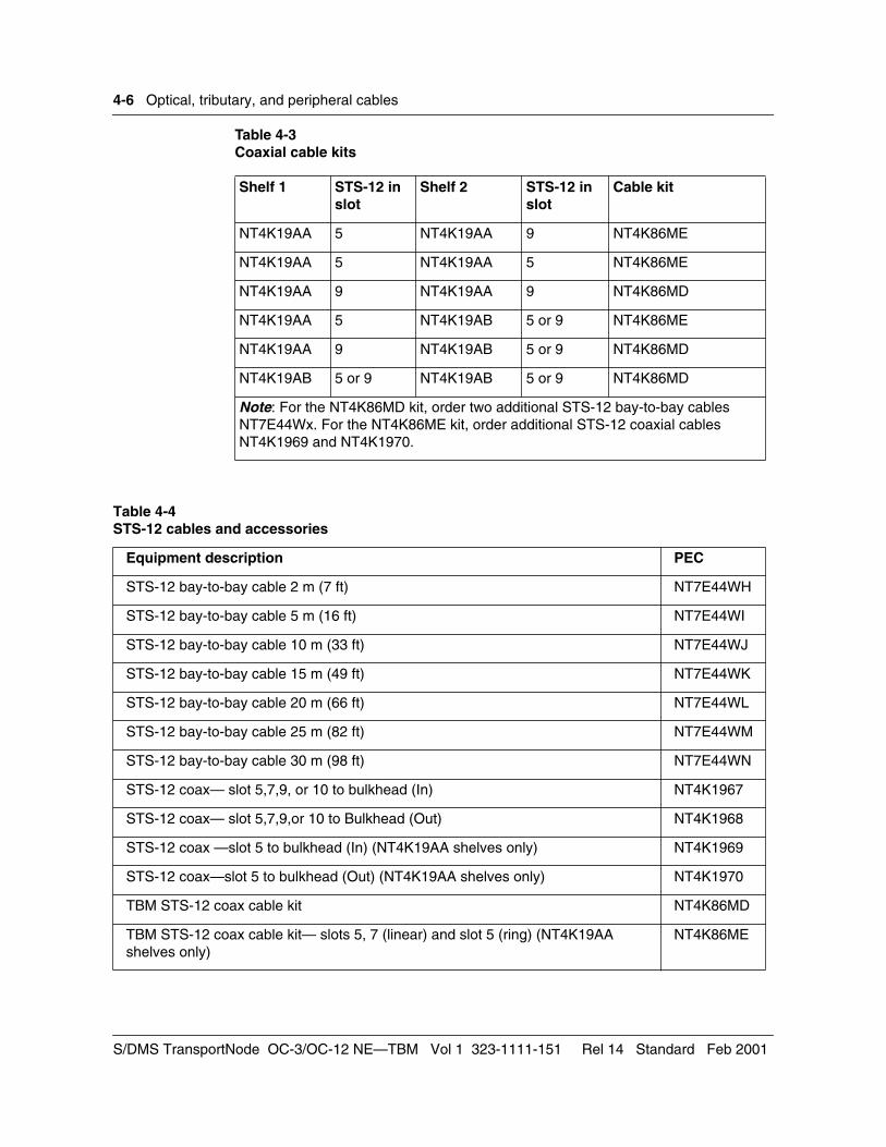
Table 4-3Coaxial cable kits
Shelf 1 STS-12 in slot
Shelf 2 STS-12 in slot
Cable kit
NT4K19AA 5 NT4K19AA 9 NT4K86ME
NT4K19AA 5 NT4K19AA 5 NT4K86ME
NT4K19AA 9 NT4K19AA 9 NT4K86MD
NT4K19AA 5 NT4K19AB 5 or 9 NT4K86ME
NT4K19AA 9 NT4K19AB 5 or 9 NT4K86MD
NT4K19AB 5 or 9 NT4K19AB 5 or 9 NT4K86MD
Note: For the NT4K86MD kit, order two additional STS-12 bay-to-bay cables NT7E44Wx. For the NT4K86ME kit, order additional STS-12 coaxial cables NT4K1969 and NT4K1970.
Table 4-4 STS-12 cables and accessories
Equipment description PEC
STS-12 bay-to-bay cable 2 m (7 ft) NT7E44WH
STS-12 bay-to-bay cable 5 m (16 ft) NT7E44WI
STS-12 bay-to-bay cable 10 m (33 ft) NT7E44WJ
STS-12 bay-to-bay cable 15 m (49 ft) NT7E44WK
STS-12 bay-to-bay cable 20 m (66 ft) NT7E44WL
STS-12 bay-to-bay cable 25 m (82 ft) NT7E44WM
STS-12 bay-to-bay cable 30 m (98 ft) NT7E44WN
STS-12 coax— slot 5,7,9, or 10 to bulkhead (In) NT4K1967
STS-12 coax— slot 5,7,9,or 10 to Bulkhead (Out) NT4K1968
STS-12 coax —slot 5 to bulkhead (In) (NT4K19AA shelves only) NT4K1969
STS-12 coax—slot 5 to bulkhead (Out) (NT4K19AA shelves only) NT4K1970
TBM STS-12 coax cable kit NT4K86MD
TBM STS-12 coax cable kit— slots 5, 7 (linear) and slot 5 (ring) (NT4K19AA shelves only)
NT4K86ME
S/DMS TransportNode OC-3/OC-12 NE—TBM Vol 1 323-1111-151 Rel 14 Standard Feb 2001
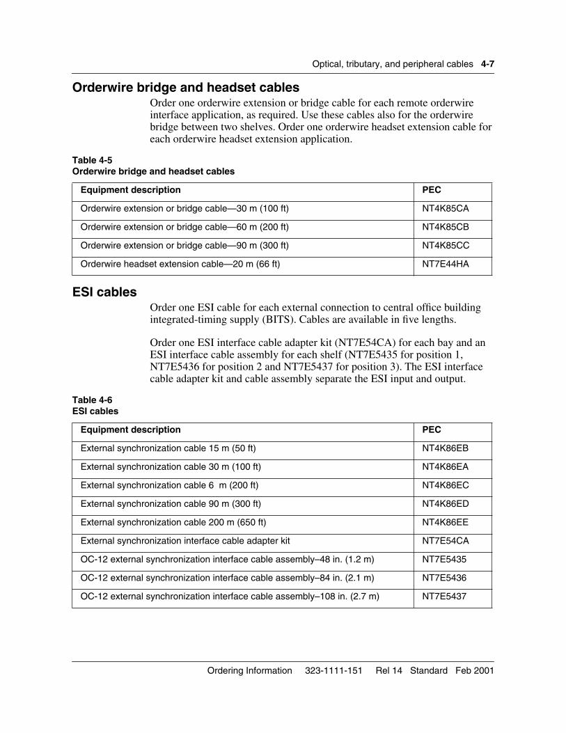
Optical, tributary, and peripheral cables 4-7
Orderwire bridge and headset cablesOrder one orderwire extension or bridge cable for each remote orderwire interface application, as required. Use these cables also for the orderwire bridge between two shelves. Order one orderwire headset extension cable for each orderwire headset extension application.
ESI cablesOrder one ESI cable for each external connection to central office building integrated-timing supply (BITS). Cables are available in five lengths.
Order one ESI interface cable adapter kit (NT7E54CA) for each bay and an ESI interface cable assembly for each shelf (NT7E5435 for position 1, NT7E5436 for position 2 and NT7E5437 for position 3). The ESI interface cable adapter kit and cable assembly separate the ESI input and output.
Table 4-5Orderwire bridge and headset cables
Equipment description PEC
Orderwire extension or bridge cable—30 m (100 ft) NT4K85CA
Orderwire extension or bridge cable—60 m (200 ft) NT4K85CB
Orderwire extension or bridge cable—90 m (300 ft) NT4K85CC
Orderwire headset extension cable—20 m (66 ft) NT7E44HA
Table 4-6 ESI cables
Equipment description PEC
External synchronization cable 15 m (50 ft) NT4K86EB
External synchronization cable 30 m (100 ft) NT4K86EA
External synchronization cable 6 m (200 ft) NT4K86EC
External synchronization cable 90 m (300 ft) NT4K86ED
External synchronization cable 200 m (650 ft) NT4K86EE
External synchronization interface cable adapter kit NT7E54CA
OC-12 external synchronization interface cable assembly–48 in. (1.2 m) NT7E5435
OC-12 external synchronization interface cable assembly–84 in. (2.1 m) NT7E5436
OC-12 external synchronization interface cable assembly–108 in. (2.7 m) NT7E5437
Ordering Information 323-1111-151 Rel 14 Standard Feb 2001
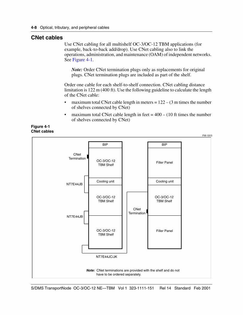
4-8 Optical, tributary, and peripheral cables
CNet cablesUse CNet cabling for all multishelf OC-3/OC-12 TBM applications (for example, back-to-back add/drop). Use CNet cabling also to link the operations, administration, and maintenance (OAM) of independent networks. See Figure 4-1.
Note: Order CNet termination plugs only as replacements for original plugs. CNet termination plugs are included as part of the shelf.
Order one cable for each shelf-to-shelf connection. CNet cabling distance limitation is 122 m (400 ft). Use the following guideline to calculate the length of the CNet cable:
• maximum total CNet cable length in meters = 122 – (3 m times the number of shelves connected by CNet)
• maximum total CNet cable length in feet = 400 – (10 ft times the number of shelves connected by CNet)
Figure 4-1CNet cables
FW-1915
Note: CNet terminations are provided with the shelf and do not have to be ordered separately.
NT7E44JC/JK
CNetTermination
NT7E44JB
OC-3/OC-12TBM Shelf
NT7E44JB
BIP BIP
OC-3/OC-12TBM Shelf
OC-3/OC-12TBM Shelf
OC-3/OC-12TBM Shelf
Filler Panel
Filler Panel
CNetTermination
Cooling unit Cooling unit
S/DMS TransportNode OC-3/OC-12 NE—TBM Vol 1 323-1111-151 Rel 14 Standard Feb 2001
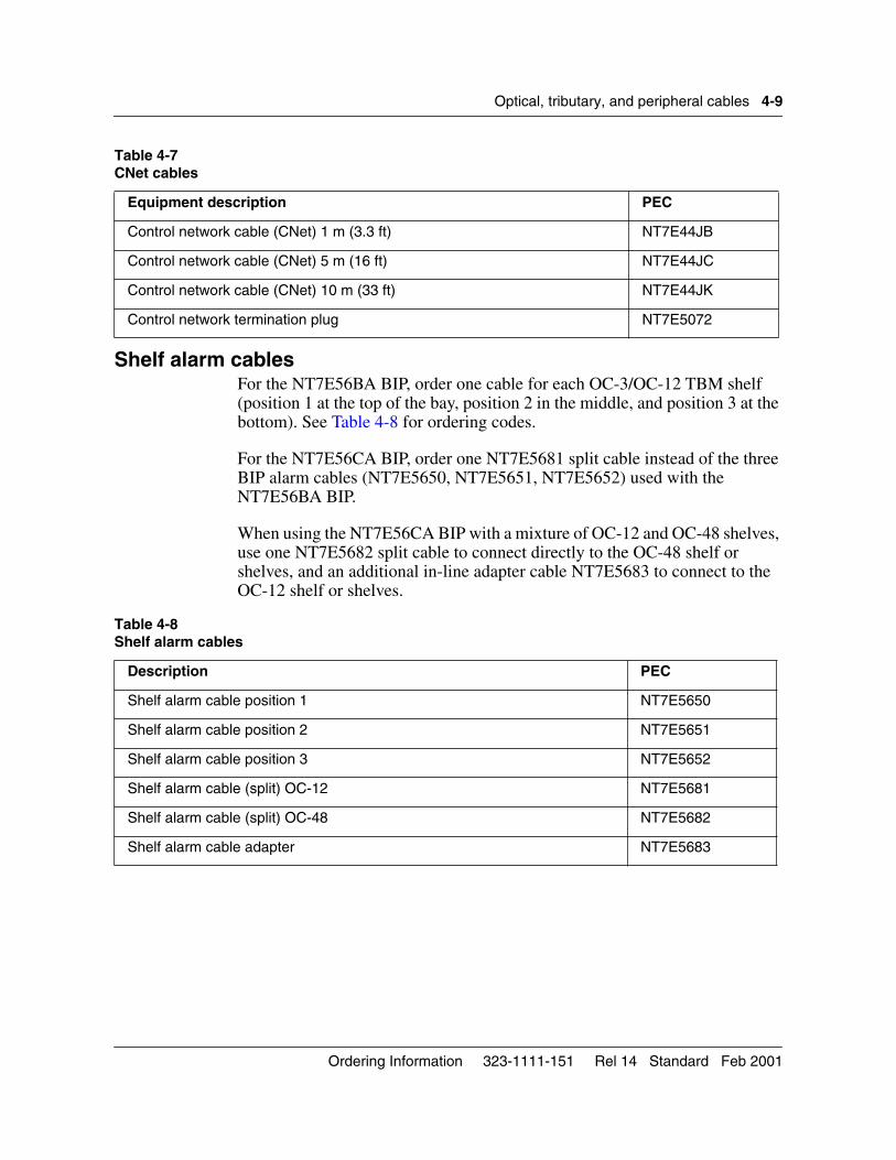
Optical, tributary, and peripheral cables 4-9
Shelf alarm cablesFor the NT7E56BA BIP, order one cable for each OC-3/OC-12 TBM shelf (position 1 at the top of the bay, position 2 in the middle, and position 3 at the bottom). See Table 4-8 for ordering codes.
For the NT7E56CA BIP, order one NT7E5681 split cable instead of the three BIP alarm cables (NT7E5650, NT7E5651, NT7E5652) used with the NT7E56BA BIP.
When using the NT7E56CA BIP with a mixture of OC-12 and OC-48 shelves, use one NT7E5682 split cable to connect directly to the OC-48 shelf or shelves, and an additional in-line adapter cable NT7E5683 to connect to the OC-12 shelf or shelves.
Table 4-7CNet cables
Equipment description PEC
Control network cable (CNet) 1 m (3.3 ft) NT7E44JB
Control network cable (CNet) 5 m (16 ft) NT7E44JC
Control network cable (CNet) 10 m (33 ft) NT7E44JK
Control network termination plug NT7E5072
Table 4-8Shelf alarm cables
Description PEC
Shelf alarm cable position 1 NT7E5650
Shelf alarm cable position 2 NT7E5651
Shelf alarm cable position 3 NT7E5652
Shelf alarm cable (split) OC-12 NT7E5681
Shelf alarm cable (split) OC-48 NT7E5682
Shelf alarm cable adapter NT7E5683
Ordering Information 323-1111-151 Rel 14 Standard Feb 2001
4-10 Optical, tributary, and peripheral cables
User interface cablesIf no BIP integral modem is ordered, use the 9/25 pin user interface cable to connect the 9-pin side-wing connector (user interface port 1) on the TBM terminal to a modem. With a null-modem cable adapter attached to this cable, the 9-pin side-wing connector can be connected to a terminal or printer. Also, with a null-modem cable adapter attached, the BIP modem cable can be connected from the local craft access panel (LCAP) user interface port 2 to a 9-pin port on a terminal (for example, a laptop).
Use the 25/25-pin user interface cable to connect the VT100 User Interface (user interface port 2). Order length as required. You can also use this cable along with a null modem cable adapter to connect user interface port 2 to a modem.
The null-modem cable adapter crosses wires 2 and 3 for all user interface cables. The combination of user interface cable and adapter allows any user interface port on the OC-3/OC-12 TBM network element to be used for VDT (DTE) or modem (DCE) access.
Use the null-modem cable adapter to connect a modem to user interface port 2 only.
Use the OPC cable to access the OPC processor directly during installation testing to allow direct access to the OPC user interface without first logging in to the network element user interface. The cable connects the OPC port 1 (connector J09) on the left side of the TBM shelf to a local VT100-type terminal or printer (NT7E44RA/RB), a laptop terminal (NT7E44SA/SB), an X.25 modem (NT7E44QA/QB), or a modem for a remote printer or terminal (NT7E44EA/EB). The cable connects from the OPC port 2 (connector J07) on the left side of the TBM shelf to an X.25 modem (NT7E44XA/XB). Order one cable for each system.
Note: Nortel Networks supports only the international models of DEC VT320 and VT420 because the North American models do not have a standard RS-232 interface.
S/DMS TransportNode OC-3/OC-12 NE—TBM Vol 1 323-1111-151 Rel 14 Standard Feb 2001
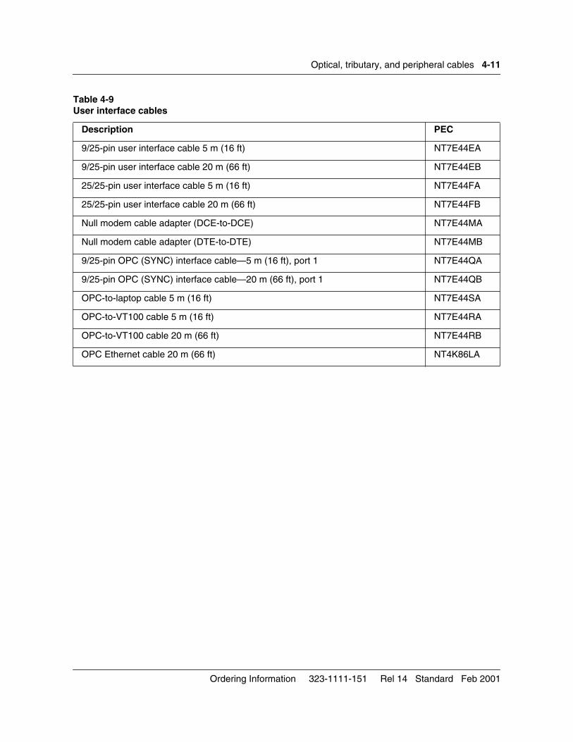
Optical, tributary, and peripheral cables 4-11
Table 4-9User interface cables
Description PEC
9/25-pin user interface cable 5 m (16 ft) NT7E44EA
9/25-pin user interface cable 20 m (66 ft) NT7E44EB
25/25-pin user interface cable 5 m (16 ft) NT7E44FA
25/25-pin user interface cable 20 m (66 ft) NT7E44FB
Null modem cable adapter (DCE-to-DCE) NT7E44MA
Null modem cable adapter (DTE-to-DTE) NT7E44MB
9/25-pin OPC (SYNC) interface cable—5 m (16 ft), port 1 NT7E44QA
9/25-pin OPC (SYNC) interface cable—20 m (66 ft), port 1 NT7E44QB
OPC-to-laptop cable 5 m (16 ft) NT7E44SA
OPC-to-VT100 cable 5 m (16 ft) NT7E44RA
OPC-to-VT100 cable 20 m (66 ft) NT7E44RB
OPC Ethernet cable 20 m (66 ft) NT4K86LA
Ordering Information 323-1111-151 Rel 14 Standard Feb 2001
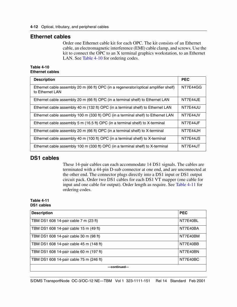
4-12 Optical, tributary, and peripheral cables
Ethernet cablesOrder one Ethernet cable kit for each OPC. The kit consists of an Ethernet cable, an electromagnetic interference (EMI) cable clamp, and screws. Use the kit to connect the OPC to an X terminal graphics workstation, to an Ethernet LAN. See Table 4-10 for ordering codes.
DS1 cablesThese 14-pair cables can each accommodate 14 DS1 signals. The cables are terminated with a 44-pin D-sub connector at one end, and are unconnected at the other end. The connector plugs directly into a DS1 input or DS1 output circuit pack. Order two DS1 cables for each DS1 VT mapper (one cable for input and one cable for output). Order length as require. See Table 4-11 for ordering codes.
Table 4-10Ethernet cables
Description PEC
Ethernet cable assembly 20 m (66 ft) OPC (in a regenerator/optical amplifier shelf) to Ethernet LAN
NT7E44GG
Ethernet cable assembly 20 m (66 ft) OPC (in a terminal shelf) to Ethernet LAN NT7E44JE
Ethernet cable assembly 40 m (132 ft) OPC (in a terminal shelf) to Ethernet LAN NT7E44JU
Ethernet cable assembly 100 m (330 ft) OPC (in a terminal shelf) to Ethernet LAN NT7E44JV
Ethernet cable assembly 5 m (16.5 ft) OPC (in a terminal shelf) to X-terminal NT7E44JF
Ethernet cable assembly 20 m (66 ft) OPC (in a terminal shelf) to X-terminal NT7E44JH
Ethernet cable assembly 40 m (100 ft) OPC (in a terminal shelf) to X-terminal NT7E44JS
Ethernet cable assembly 100 m (330 ft) OPC (in a terminal shelf) to X-terminal NT7E44JT
Table 4-11DS1 cables
Description PEC
TBM DS1 608 14-pair cable 7 m (23 ft) NT7E40BL
TBM DS1 608 14-pair cable 15 m (49 ft) NT7E40BA
TBM DS1 608 14-pair cable 30 m (98 ft) NT7E40BM
TBM DS1 608 14-pair cable 45 m (148 ft) NT7E40BB
TBM DS1 608 14-pair cable 60 m (197 ft) NT7E40BN
TBM DS1 608 14-pair cable 75 m (246 ft) NT7E40BC
—continued—
S/DMS TransportNode OC-3/OC-12 NE—TBM Vol 1 323-1111-151 Rel 14 Standard Feb 2001
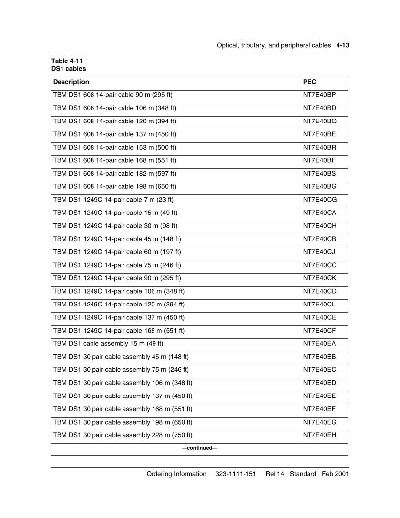
Optical, tributary, and peripheral cables 4-13
TBM DS1 608 14-pair cable 90 m (295 ft) NT7E40BP
TBM DS1 608 14-pair cable 106 m (348 ft) NT7E40BD
TBM DS1 608 14-pair cable 120 m (394 ft) NT7E40BQ
TBM DS1 608 14-pair cable 137 m (450 ft) NT7E40BE
TBM DS1 608 14-pair cable 153 m (500 ft) NT7E40BR
TBM DS1 608 14-pair cable 168 m (551 ft) NT7E40BF
TBM DS1 608 14-pair cable 182 m (597 ft) NT7E40BS
TBM DS1 608 14-pair cable 198 m (650 ft) NT7E40BG
TBM DS1 1249C 14-pair cable 7 m (23 ft) NT7E40CG
TBM DS1 1249C 14-pair cable 15 m (49 ft) NT7E40CA
TBM DS1 1249C 14-pair cable 30 m (98 ft) NT7E40CH
TBM DS1 1249C 14-pair cable 45 m (148 ft) NT7E40CB
TBM DS1 1249C 14-pair cable 60 m (197 ft) NT7E40CJ
TBM DS1 1249C 14-pair cable 75 m (246 ft) NT7E40CC
TBM DS1 1249C 14-pair cable 90 m (295 ft) NT7E40CK
TBM DS1 1249C 14-pair cable 106 m (348 ft) NT7E40CD
TBM DS1 1249C 14-pair cable 120 m (394 ft) NT7E40CL
TBM DS1 1249C 14-pair cable 137 m (450 ft) NT7E40CE
TBM DS1 1249C 14-pair cable 168 m (551 ft) NT7E40CF
TBM DS1 cable assembly 15 m (49 ft) NT7E40EA
TBM DS1 30 pair cable assembly 45 m (148 ft) NT7E40EB
TBM DS1 30 pair cable assembly 75 m (246 ft) NT7E40EC
TBM DS1 30 pair cable assembly 106 m (348 ft) NT7E40ED
TBM DS1 30 pair cable assembly 137 m (450 ft) NT7E40EE
TBM DS1 30 pair cable assembly 168 m (551 ft) NT7E40EF
TBM DS1 30 pair cable assembly 198 m (650 ft) NT7E40EG
TBM DS1 30 pair cable assembly 228 m (750 ft) NT7E40EH
—continued—
Table 4-11DS1 cables
Description PEC
Ordering Information 323-1111-151 Rel 14 Standard Feb 2001
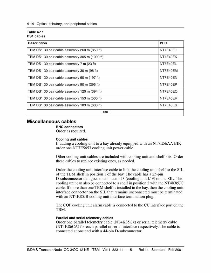
4-14 Optical, tributary, and peripheral cables
Miscellaneous cablesBNC connectorsOrder as required.
Cooling unit cablesIf adding a cooling unit to a bay already equipped with an NT7E56AA BIP, order one NT7E5653 cooling unit power cable.
Other cooling unit cables are included with cooling unit and shelf kits. Order these cables to replace existing ones, as needed.
Order the cooling unit interface cable to link the cooling unit shelf to the SIL of the TBM shelf in position 1 of the bay. The cable has a 25-pin D-subconnector that goes to connector J3 (cooling unit I/ F) on the SIL. The cooling unit can also be connected to a shelf in position 2 with the NT4K85JC cable. If more than one TBM shelf is installed in the bay, then the cooling unit interface connector on the SIL that remains unconnected must be terminated with an NT4K85JB cooling unit interface termination plug.
The COP cooling unit alarm cable is connected to the CU interface port on the TBM.
Parallel and serial telemetry cablesOrder one parallel telemetry cable (NT4K85Gx) or serial telemetry cable (NT4K86CA) for each parallel or serial interface respectively. The cable is connected at one end with a 44-pin D-subconnector.
TBM DS1 30 pair cable assembly 260 m (850 ft) NT7E40EJ
TBM DS1 30 pair cable assembly 305 m (1000 ft) NT7E40EK
TBM DS1 30 pair cable assembly 7 m (23 ft) NT7E40EL
TBM DS1 30 pair cable assembly 30 m (98 ft) NT7E40EM
TBM DS1 30 pair cable assembly 60 m (197 ft) NT7E40EN
TBM DS1 30 pair cable assembly 90 m (295 ft) NT7E40EP
TBM DS1 30 pair cable assembly 120 m (394 ft) NT7E40EQ
TBM DS1 30 pair cable assembly 153 m (500 ft) NT7E40ER
TBM DS1 30 pair cable assembly 183 m (600 ft) NT7E40ES
—end—
Table 4-11DS1 cables
Description PEC
S/DMS TransportNode OC-3/OC-12 NE—TBM Vol 1 323-1111-151 Rel 14 Standard Feb 2001
Optical, tributary, and peripheral cables 4-15
COP/LCAP cableOrder one TBM COP/LCAP cable for each shelf equipped. This cable links the TBM shelf side interconnect left (SIL) circuit pack to the LCAP. The cable has a 44-pin D-subconnector that goes to connector J4 (LCAP I/F) on the SIL. Order one cable to connect to the TBM shelf. The NT4K86Bx is required only if the BIP modem is used. Order lengths according to customer requirements.
Modem cablesOrder one cable to connect to the TBM shelf. The NT7E44DD/E/F is required only if the BIP modem is used. Order lengths according to the position of the shelf in the bay.
TBM power cable adapter and TBM power termination kit (for BIP)The NT4K1951 power cable adapter is included with all FiberWorld shelves to connect the shelf to the NT7E56BA BIP.
To add shelves to an existing bay already equipped with an NT7E56AA BIP, order one NT4K1950 TBM power termination kit for each NT4K19AA or NT4K19AB shelf.
If adding a cooling unit to an existing bay already equipped with an NT7E56AA BIP, order one NT7E5653 cooling unit power cable.
If replacing an NT7E56AA BIP with an NT7E56BA BIP, order one NT4K1951 power cable adapter for each NT4K19AA or NT4K19AB shelf.
PSTN interface cable and adapterThe cable and adapter provides connection to the public switched telephone network (PSTN). Order one for each site.
Ordering Information 323-1111-151 Rel 14 Standard Feb 2001
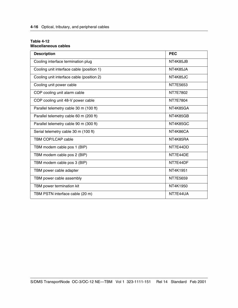
4-16 Optical, tributary, and peripheral cables
Table 4-12Miscellaneous cables
Description PEC
Cooling interface termination plug NT4K85JB
Cooling unit interface cable (position 1) NT4K85JA
Cooling unit interface cable (position 2) NT4K85JC
Cooling unit power cable NT7E5653
COP cooling unit alarm cable NT7E7802
COP cooling unit 48-V power cable NT7E7804
Parallel telemetry cable 30 m (100 ft) NT4K85GA
Parallel telemetry cable 60 m (200 ft) NT4K85GB
Parallel telemetry cable 90 m (300 ft) NT4K85GC
Serial telemetry cable 30 m (100 ft) NT4K86CA
TBM COP/LCAP cable NT4K85RA
TBM modem cable pos 1 (BIP) NT7E44DD
TBM modem cable pos 2 (BIP) NT7E44DE
TBM modem cable pos 3 (BIP) NT7E44DF
TBM power cable adapter NT4K1951
TBM power cable assembly NT7E5659
TBM power termination kit NT4K1950
TBM PSTN interface cable (20 m) NT7E44UA
S/DMS TransportNode OC-3/OC-12 NE—TBM Vol 1 323-1111-151 Rel 14 Standard Feb 2001
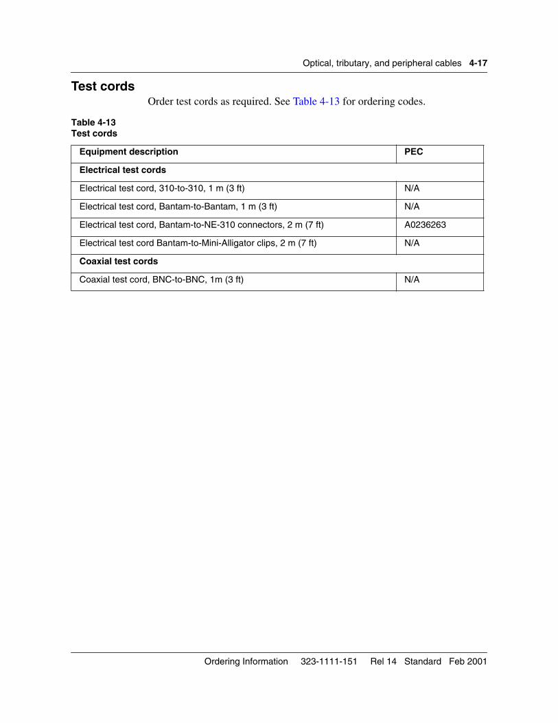
Optical, tributary, and peripheral cables 4-17
Test cordsOrder test cords as required. See Table 4-13 for ordering codes.
Table 4-13Test cords
Equipment description PEC
Electrical test cords
Electrical test cord, 310-to-310, 1 m (3 ft) N/A
Electrical test cord, Bantam-to-Bantam, 1 m (3 ft) N/A
Electrical test cord, Bantam-to-NE-310 connectors, 2 m (7 ft) A0236263
Electrical test cord Bantam-to-Mini-Alligator clips, 2 m (7 ft) N/A
Coaxial test cords
Coaxial test cord, BNC-to-BNC, 1m (3 ft) N/A
Ordering Information 323-1111-151 Rel 14 Standard Feb 2001

4-18 Optical, tributary, and peripheral cables
S/DMS TransportNode OC-3/OC-12 NE—TBM Vol 1 323-1111-151 Rel 14 Standard Feb 2001
5-1
Software 5-This chapter describes how to order software for an operations controller (OPC) for an OC-3/OC-12 network element. Software and software licenses are identified by a product engineering code (PEC).
Software loadsAn S/DMS TransportNode includes one (primary) or two (primary and backup) OPCs. The OPC manages the software that makes the hardware operational. Software is purchased separately and consists of software loads and software licences.
Order one software load for every system. The load is delivered on a digital data storage (DDS) tape and consists of an OPC load and a network element load. Order one load for each OPC module.
When you order a TBM shelf, you receive a Right-to-copy certificate. This certificate permits the most recent software load version (as of the date of purchase) to be loaded in that shelf. See Table 5-1 for ordering codes.
Release 14OC-12 TBM Release 14 introduces the following features:
• Release 14 software along with the NT7E08BA mapper provide C-bit transparency, and AIS dectection and alarming.
• NE A and NE Z values are checked during audits and users are allowed to correct mismatches if they occur.
• Matched node enhancements provides two new user initiated protection requests, Lockout of Protection and Manual Switch.
• OC-3 Trib Sync Status Messaging
Release 13.11/13.12OC-3/OC-12 TBM Rel 13.11/13.12 introduces the following features:
• Matched nodes on VTM bidirectional line-switched rings (BLSR) provides the ability to interconnect a BLSR with one or more SONET rings, offering greater protection between rings.
Ordering Information 323-1111-151 Rel 14 Standard Feb 2001
5-2 Software
• Matched nodes in-service edit permits the conversion of matched-node connections to non-matched-node connections, and some non-matched-nodes connections to matched-node connections. In-service edit also permits the matched-node protection scheme to be modified (DCW to DCP and vice-versa). Finally, in-service edit permits the tributary at the primary or secondary gateway to be modified.
• DS1 ESF synchronization status messaging provides the ability to send clock quality levels from the ESK to the BITS at network elements that provide timing distribution, and from the BITS to the ESI at externally timed network elements.
• STS and VT in-service rollover
• firmware download enhancements
• software upgrade advancements
• performance monitoring enhancements
• extended range NE ID
• AD-2000
• target identifier address resolution protocol (TARP) transparency
• NE enhancements
• new and enhanced OPC tools
Release 11.2OC-3/OC-12 TBM Rel 11.2 introduces the following features:
• OC-12 virtual tributary bandwidth management (VTM) circuit pack
• VTM rings. In VTM rings, the VTM optics provide VTM as well as the functionality of the ring loopback circuit packs and overhead bridge circuit packs
• synchronization status messaging
Release 10.03OC-3/OC-12 TBM Rel 10.03 introduces the following features:
• matched-node connections on OC-12 TA-1230 rings using STS-1 connections
• enhanced SONET data communication channel (SDCC) on the data communications user interface to allow the user to change parameters for the link access procedure on the D link (necessary for network interoperability) and to enable or disable the SONET data communication channel link (providing better network security)
• support for First Alert alarm indication
• enhanced support for TL1 access through the OPC UNIX shell
S/DMS TransportNode OC-3/OC-12 NE—TBM Vol 1 323-1111-151 Rel 14 Standard Feb 2001
Software 5-3
• other operations, administration, and maintenance (OAM) enhancements including the support of Transmission Control Protocol/Internet Protocol (TCP/IP) applications using TCP/IP over X.25
Release 9.01OC-3/OC-12 TBM Rel 9.01 introduces the following:
• DS1 path performance monitoring, universal path trace, OC-3/OC-12 PM compliance, external synchronization interface (ESI) source protection timing distribution, ring lockout, provisioning of STS-3c connections, DS3 out-of-frequency alarms, and automated NE daylight saving time
• OAM features including the implementation of the open systems interconnection (OSI) interface, and TL1 and OPC enhancements
Release 8.10OC-3/OC-12 TBM Rel 8.10 introduces the following features:
• adds 1+1 protection to OC-3 optical tributaries and extends their application to add-drop multiplexer (ADM) and ring ADM configurations
• STS-1 tributaries
• enhanced timing deviation detection and recovery
Release 7.10OC-3/OC-12 TBM Rel 7.10 introduces the following features:
• TA-1230 ring, a bidirectional line-switched ring (BLSR) configuration for TBM, and OC-3 optical tributaries on OC-12 TBM shelves (for terminals only). OC-12 regenerators are not supported in this release. ADM shelves with no tributaries can extend reach.
Release 6.01OC-3/OC-12 TBM Rel 6.01 adds the following functionality:
• ADM
• full bandwidth DS1/DS3 mix configuration
• 336 DS1 capability
• user-selectable ESI line timing
• STS-1 flexible time slot assignment
• STS-1 Path performance monitoring on DS1 services
• DS3 clear channel
Release 5.00OC-3/OC-12 TBM Rel 5.00 adds the following:
• increased DS1 capacity (84 DS1s for OC-3, 168 DS1s for OC-12)
• OC-3 DS1/DS3 mix configuration
Ordering Information 323-1111-151 Rel 14 Standard Feb 2001
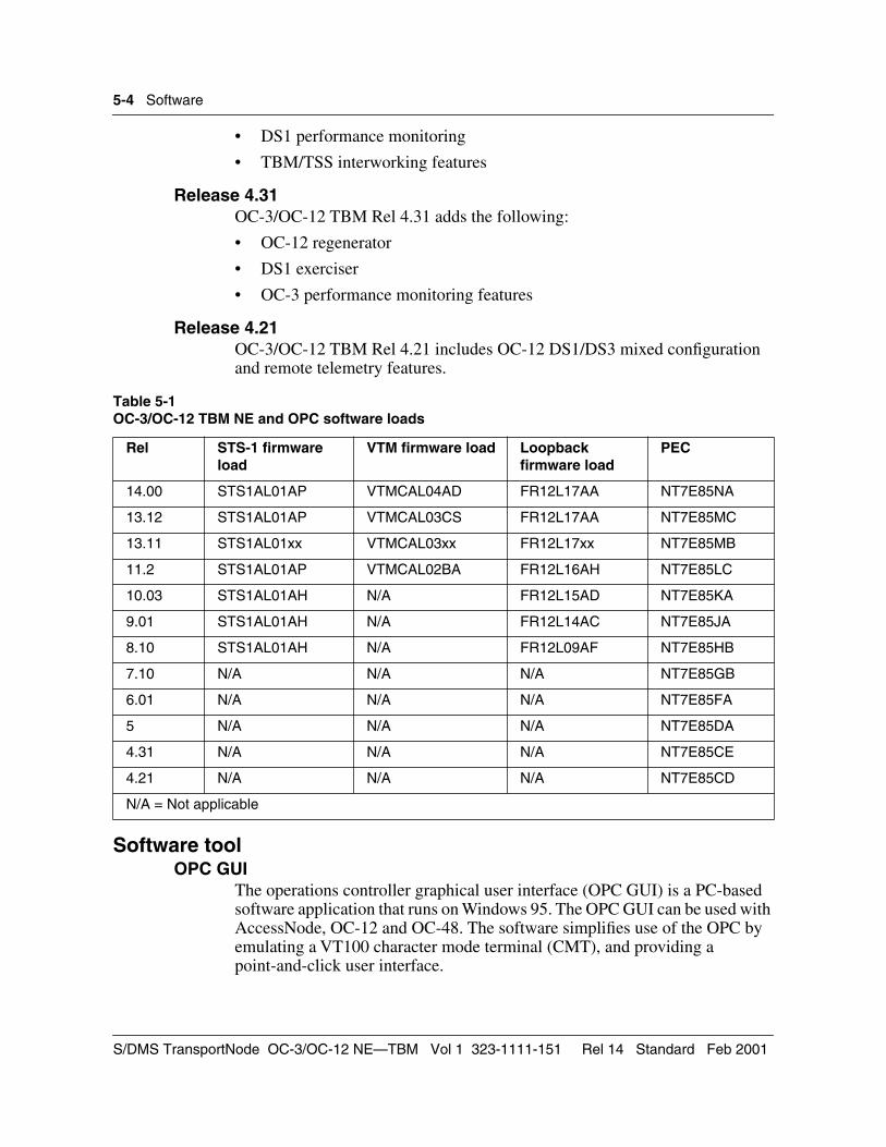
5-4 Software
• DS1 performance monitoring
• TBM/TSS interworking features
Release 4.31OC-3/OC-12 TBM Rel 4.31 adds the following:
• OC-12 regenerator
• DS1 exerciser
• OC-3 performance monitoring features
Release 4.21OC-3/OC-12 TBM Rel 4.21 includes OC-12 DS1/DS3 mixed configuration and remote telemetry features.
Software toolOPC GUI
The operations controller graphical user interface (OPC GUI) is a PC-based software application that runs on Windows 95. The OPC GUI can be used with AccessNode, OC-12 and OC-48. The software simplifies use of the OPC by emulating a VT100 character mode terminal (CMT), and providing a point-and-click user interface.
Table 5-1OC-3/OC-12 TBM NE and OPC software loads
Rel STS-1 firmware load
VTM firmware load Loopback firmware load
PEC
14.00 STS1AL01AP VTMCAL04AD FR12L17AA NT7E85NA
13.12 STS1AL01AP VTMCAL03CS FR12L17AA NT7E85MC
13.11 STS1AL01xx VTMCAL03xx FR12L17xx NT7E85MB
11.2 STS1AL01AP VTMCAL02BA FR12L16AH NT7E85LC
10.03 STS1AL01AH N/A FR12L15AD NT7E85KA
9.01 STS1AL01AH N/A FR12L14AC NT7E85JA
8.10 STS1AL01AH N/A FR12L09AF NT7E85HB
7.10 N/A N/A N/A NT7E85GB
6.01 N/A N/A N/A NT7E85FA
5 N/A N/A N/A NT7E85DA
4.31 N/A N/A N/A NT7E85CE
4.21 N/A N/A N/A NT7E85CD
N/A = Not applicable
S/DMS TransportNode OC-3/OC-12 NE—TBM Vol 1 323-1111-151 Rel 14 Standard Feb 2001
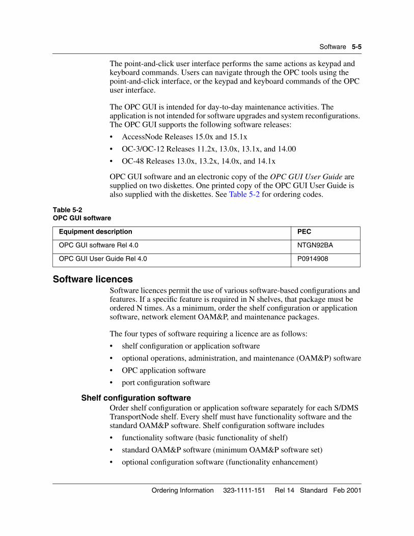
Software 5-5
The point-and-click user interface performs the same actions as keypad and keyboard commands. Users can navigate through the OPC tools using the point-and-click interface, or the keypad and keyboard commands of the OPC user interface.
The OPC GUI is intended for day-to-day maintenance activities. The application is not intended for software upgrades and system reconfigurations. The OPC GUI supports the following software releases:
• AccessNode Releases 15.0x and 15.1x
• OC-3/OC-12 Releases 11.2x, 13.0x, 13.1x, and 14.00
• OC-48 Releases 13.0x, 13.2x, 14.0x, and 14.1x
OPC GUI software and an electronic copy of the OPC GUI User Guide are supplied on two diskettes. One printed copy of the OPC GUI User Guide is also supplied with the diskettes. See Table 5-2 for ordering codes.
Software licencesSoftware licences permit the use of various software-based configurations and features. If a specific feature is required in N shelves, that package must be ordered N times. As a minimum, order the shelf configuration or application software, network element OAM&P, and maintenance packages.
The four types of software requiring a licence are as follows:
• shelf configuration or application software
• optional operations, administration, and maintenance (OAM&P) software
• OPC application software
• port configuration software
Shelf configuration software Order shelf configuration or application software separately for each S/DMS TransportNode shelf. Every shelf must have functionality software and the standard OAM&P software. Shelf configuration software includes
• functionality software (basic functionality of shelf)
• standard OAM&P software (minimum OAM&P software set)
• optional configuration software (functionality enhancement)
Table 5-2OPC GUI software
Equipment description PEC
OPC GUI software Rel 4.0 NTGN92BA
OPC GUI User Guide Rel 4.0 P0914908
Ordering Information 323-1111-151 Rel 14 Standard Feb 2001
5-6 Software
OC-3/OC-12 1+1 DS3 or DS1 terminalEvery OC-3/OC-12 network element must be assigned a configuration type. The OC-3/OC-12 terminal can support DS1, DS3, STS-1, OC-3 tributaries (on OC-12 only), and various mixes of these tributaries.
Optional OAM&P softwareOptional OAM&P software resides on both the OPC and network elements to complement the standard OAM&P functionality. Order all optional OAM&P features separately for each S/DMS TransportNode shelf.
OC-3/OC-12 terminal ADM OAM&P featuresOrder the OC-3 terminal/ADM OAM&P features license for every OC-3 terminal or ADM shelf in the system.
Order the OC-12 terminal/ADM OAM&P features license for every OC-12 terminal or ADM shelf in the system.
OPC application softwareApplication software for the primary OPC is included in the standard OAM&P software package. The OPC application software enhances this base capability with additional features such as a standby OPC and OPC-to-OPC file transfer. Order OPC application software separately for each OPC.
OPC applicationOrder the OPC application license for every primary OPC module. Order one primary OPC TL1 or OSS license to support TL1 or OSS on a primary OPC.
Backup OPC and standby TL1Order a backup OPC software license if a backup OPC is required. Order one license for each backup OPC. Order one Standby TL1 or OSS license to support TL1 or OSS on a backup OPC.
Port configuration softwareOrder software to support user interface ports, serial telemetry (E2A TBOS), and parallel telemetry individually for each S/DMS TransportNode shelf. Contact your Nortel Networks sales representative for complete software ordering descriptions and codes.
Every OAM&P feature license provides one user interface port. For additional user interface ports, order the additional user interface license.
The SONET DCC bridgeOrder the SDCC bridge license to bridge two shelves of separate fiber systems with a CNet cable to form one OPC span of control.
Serial telemetryOrder the TBOS software license for every E2A TBOS serial port required.
S/DMS TransportNode OC-3/OC-12 NE—TBM Vol 1 323-1111-151 Rel 14 Standard Feb 2001
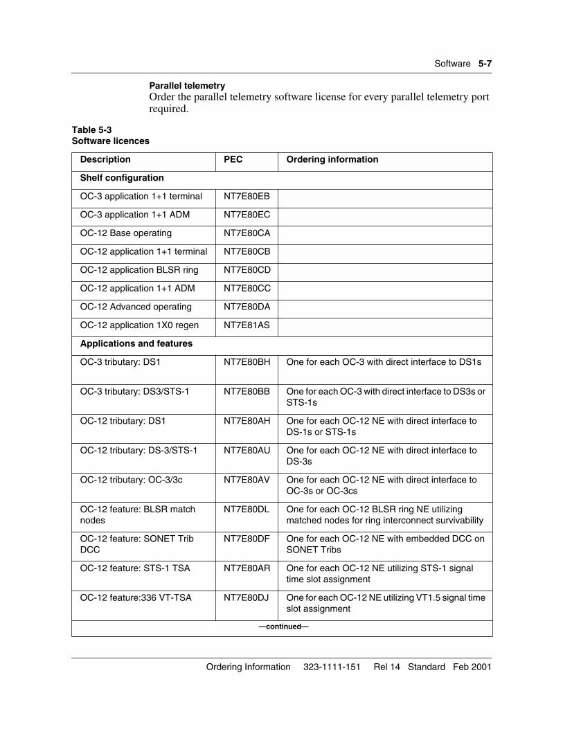
Software 5-7
Parallel telemetryOrder the parallel telemetry software license for every parallel telemetry port required.
Table 5-3 Software licences
Description PEC Ordering information
Shelf configuration
OC-3 application 1+1 terminal NT7E80EB
OC-3 application 1+1 ADM NT7E80EC
OC-12 Base operating NT7E80CA
OC-12 application 1+1 terminal NT7E80CB
OC-12 application BLSR ring NT7E80CD
OC-12 application 1+1 ADM NT7E80CC
OC-12 Advanced operating NT7E80DA
OC-12 application 1X0 regen NT7E81AS
Applications and features
OC-3 tributary: DS1 NT7E80BH One for each OC-3 with direct interface to DS1s
OC-3 tributary: DS3/STS-1 NT7E80BB One for each OC-3 with direct interface to DS3s or STS-1s
OC-12 tributary: DS1 NT7E80AH One for each OC-12 NE with direct interface to DS-1s or STS-1s
OC-12 tributary: DS-3/STS-1 NT7E80AU One for each OC-12 NE with direct interface to DS-3s
OC-12 tributary: OC-3/3c NT7E80AV One for each OC-12 NE with direct interface to OC-3s or OC-3cs
OC-12 feature: BLSR match nodes
NT7E80DL One for each OC-12 BLSR ring NE utilizing matched nodes for ring interconnect survivability
OC-12 feature: SONET Trib DCC
NT7E80DF One for each OC-12 NE with embedded DCC on SONET Tribs
OC-12 feature: STS-1 TSA NT7E80AR One for each OC-12 NE utilizing STS-1 signal time slot assignment
OC-12 feature:336 VT-TSA NT7E80DJ One for each OC-12 NE utilizing VT1.5 signal time slot assignment
—continued—
Ordering Information 323-1111-151 Rel 14 Standard Feb 2001
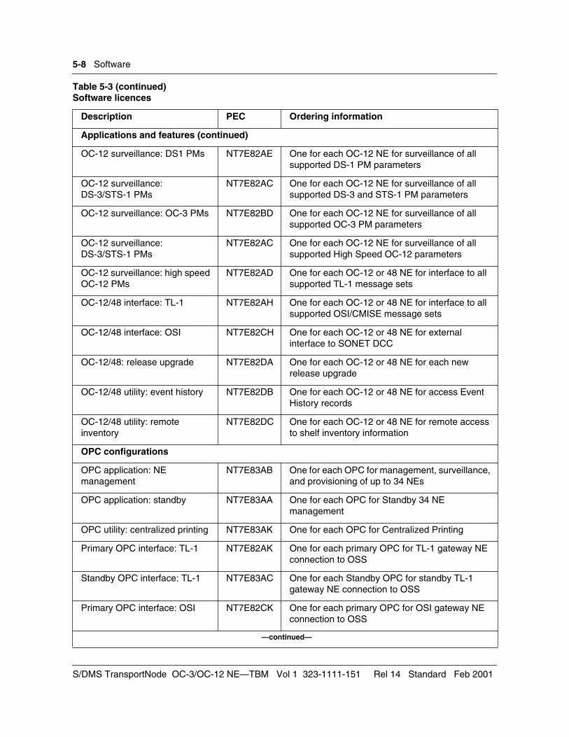
5-8 Software
Applications and features (continued)
OC-12 surveillance: DS1 PMs NT7E82AE One for each OC-12 NE for surveillance of all supported DS-1 PM parameters
OC-12 surveillance: DS-3/STS-1 PMs
NT7E82AC One for each OC-12 NE for surveillance of all supported DS-3 and STS-1 PM parameters
OC-12 surveillance: OC-3 PMs NT7E82BD One for each OC-12 NE for surveillance of all supported OC-3 PM parameters
OC-12 surveillance: DS-3/STS-1 PMs
NT7E82AC One for each OC-12 NE for surveillance of all supported High Speed OC-12 parameters
OC-12 surveillance: high speed OC-12 PMs
NT7E82AD One for each OC-12 or 48 NE for interface to all supported TL-1 message sets
OC-12/48 interface: TL-1 NT7E82AH One for each OC-12 or 48 NE for interface to all supported OSI/CMISE message sets
OC-12/48 interface: OSI NT7E82CH One for each OC-12 or 48 NE for external interface to SONET DCC
OC-12/48: release upgrade NT7E82DA One for each OC-12 or 48 NE for each new release upgrade
OC-12/48 utility: event history NT7E82DB One for each OC-12 or 48 NE for access Event History records
OC-12/48 utility: remote inventory
NT7E82DC One for each OC-12 or 48 NE for remote access to shelf inventory information
OPC configurations
OPC application: NE management
NT7E83AB One for each OPC for management, surveillance, and provisioning of up to 34 NEs
OPC application: standby NT7E83AA One for each OPC for Standby 34 NE management
OPC utility: centralized printing NT7E83AK One for each OPC for Centralized Printing
Primary OPC interface: TL-1 NT7E82AK One for each primary OPC for TL-1 gateway NE connection to OSS
Standby OPC interface: TL-1 NT7E83AC One for each Standby OPC for standby TL-1 gateway NE connection to OSS
Primary OPC interface: OSI NT7E82CK One for each primary OPC for OSI gateway NE connection to OSS
—continued—
Table 5-3 (continued)Software licences
Description PEC Ordering information
S/DMS TransportNode OC-3/OC-12 NE—TBM Vol 1 323-1111-151 Rel 14 Standard Feb 2001
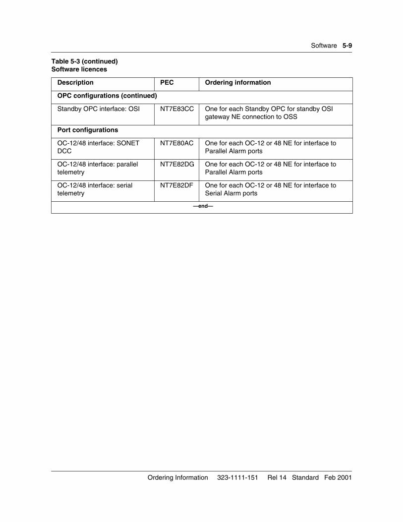
Software 5-9
OPC configurations (continued)
Standby OPC interface: OSI NT7E83CC One for each Standby OPC for standby OSI gateway NE connection to OSS
Port configurations
OC-12/48 interface: SONET DCC
NT7E80AC One for each OC-12 or 48 NE for interface to Parallel Alarm ports
OC-12/48 interface: parallel telemetry
NT7E82DG One for each OC-12 or 48 NE for interface to Parallel Alarm ports
OC-12/48 interface: serial telemetry
NT7E82DF One for each OC-12 or 48 NE for interface to Serial Alarm ports
—end—
Table 5-3 (continued)Software licences
Description PEC Ordering information
Ordering Information 323-1111-151 Rel 14 Standard Feb 2001

5-10 Software
S/DMS TransportNode OC-3/OC-12 NE—TBM Vol 1 323-1111-151 Rel 14 Standard Feb 2001
6-1
Documentation 6-This chapter describes how to order documentation related to the OC-3/OC-12 network element. The equipment is identified by a product engineering code (PEC). Other ordering codes are included, where applicable.
NTP packagesNTP packages are available to support Releases 14, 13, 11, 10, 9, 8, 6.00, 5.00, and 4.30. Individual volumes of Nortel Networks Publications (NTP) can be ordered for Releases 14, 13, 11, 10, and 9. For ordering codes, see Table 6-1. For a description of the software for each release, see “Software” on page 5-1.
NTP package NT7E65DJ supports Release 14. It introduces several security enhancements, matched node enhancements, bulk delete, request display of configuration mismatches, tributary synchronization status messaging, C-bit transparency, in-service NE renumbering, solid state OPC, automatic in service (AINS), DS1 remote test unit, network element identification, display disabled alarms, area address learning and provisioning, and TCP/IP access control for the OPC.
NTP package NT7E65DI supports Release 13. It introduces matched nodes on VTM bidirectional line-switched rings, matched nodes in-service edit, and DSI ESF synchronization status messaging. It also introduces a number of enhancements to firmware download, software upgrade, performance monitoring, the network element, and OPC tools.
NTP package NT7E65DG supports Release 11. It introduces the OC-12 VTM circuit pack, and VTM ring configuration in which the VTM optics incorporate the functionality of the ring loopback circuit packs and overhead bridge circuit packs. It also introduces VT bandwidth management in VTM rings, and synchronization status messaging.
NTP package NT7E65DF supports Rel 10. It introduces matched-node connections on OC-12 TA-1230 rings using STS-1 connections. In addition, the SDCC channel on the data communications user interface has been enhanced to allow the user to change LAPD parameters (necessary for network to interoperate) and to enable or disable the SDCC link (providing better network security). Support for First Alert alarm indication is provided. Support
Ordering Information 323-1111-151 Rel 14 Standard Feb 2001
6-2 Documentation
for TL1 access through the OPC UNIX shell has been enhanced. Other OAM enhancements include the support of TCP/IP applications using TCP/IP over X.25.
NTP package NT7E65DE supports Rel 9. It introduces DS1 path PMs, universal path trace, OC-3/OC-12 PM compliance, ESI source protection timing distribution, ring lockout, provisioning of STS-3c connections, DS3 out-of-frequency alarms, and automated NE daylight saving time. The main OAM features in this release are the implementation of the OSI interface, as well as TL1 and OPC enhancements.
NTP package NT7E65DD supports Rel 8. It introduces STS-1 tributaries on OC-3/OC-12 shelves in linear systems and on ring ADM nodes, protected OC-3 optical tributaries on OC-12 shelves in linear systems and on ring ADM nodes, and reintroduces regenerator functionality.
NTP package NT7E65DC supports Rel 7. It introduces the TA-1230 ring, a bidirectional line-switched ring (BLSR) configuration for TBM, and OC-3 optical tributaries on OC-12 TBM shelves (for linear systems only).
NTP package NT7E65DB supports Rel 6.00. It introduces add-drop multiplexer (ADM), full bandwidth DS1/DS3 mixed configuration, 336 DS1 capability, user-selectable ESI line timing, STS-1 flexible time slot assignment, STS-1 Path performance monitoring on DS1 services, and DS3 clear channel.
NTP package NT7E65DA supports Rel 5.00. It introduces increased DS1 capacity (84 DS1 tributaries for OC-3, 168 DS1 tributaries for OC-12), OC-3 DS1/DS3 mixed configuration, DS1 performance monitoring, and TBM/TSS interworking features.
NTP Addendum package NT7E66BC supports Rel 4.30. Order it to update either NT7E65AC/NT7E66AC combination, or NT7E65AD. It introduces OC-12 Regenerator, DS1 exerciser, and OC-3 performance monitoring features.
If earlier NTPs are not available to be updated, order documentation package NT7E65AE. It consists of the following:
• NT7E65AC, Rel 4.00 documentation package (base NTP)
• NT7E66AC, Rel 4.10 addendum package (OC1204)
• NT7E66BC, Rel 4.30 addendum package
Insert the addenda into the base NTP.
NTP package NT7E65AD supports Rel 4.20. It comes with the following:
• NT7E65AC, Rel 4.00 documentation package (base NTP)
S/DMS TransportNode OC-3/OC-12 NE—TBM Vol 1 323-1111-151 Rel 14 Standard Feb 2001
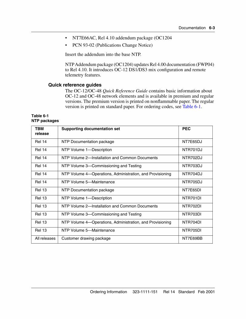
Documentation 6-3
• NT7E66AC, Rel 4.10 addendum package (OC1204
• PCN 93-02 (Publications Change Notice)
Insert the addendum into the base NTP.
NTP Addendum package (OC1204) updates Rel 4.00 documentation (FWP04) to Rel 4.10. It introduces OC-12 DS1/DS3 mix configuration and remote telemetry features.
Quick reference guidesThe OC-12/OC-48 Quick Reference Guide contains basic information about OC-12 and OC-48 network elements and is available in premium and regular versions. The premium version is printed on nonflammable paper. The regular version is printed on standard paper. For ordering codes, see Table 6-1.
Table 6-1 NTP packages
TBM release
Supporting documentation set PEC
Rel 14 NTP Documentation package NT7E65DJ
Rel 14 NTP Volume 1—Description NTR701DJ
Rel 14 NTP Volume 2—Installation and Common Documents NTR702DJ
Rel 14 NTP Volume 3—Commissioning and Testing NTR703DJ
Rel 14 NTP Volume 4—Operations, Administration, and Provisioning NTR704DJ
Rel 14 NTP Volume 5—Maintenance NTR705DJ
Rel 13 NTP Documentation package NT7E65DI
Rel 13 NTP Volume 1—Description NTR701DI
Rel 13 NTP Volume 2—Installation and Common Documents NTR702DI
Rel 13 NTP Volume 3—Commissioning and Testing NTR703DI
Rel 13 NTP Volume 4—Operations, Administration, and Provisioning NTR704DI
Rel 13 NTP Volume 5—Maintenance NTR705DI
All releases Customer drawing package NT7E69BB
Ordering Information 323-1111-151 Rel 14 Standard Feb 2001
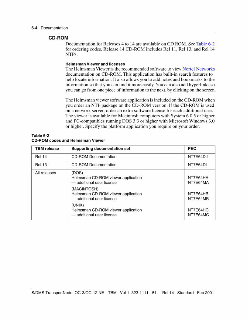
6-4 Documentation
CD-ROMDocumentation for Releases 4 to 14 are available on CD ROM. See Table 6-2 for ordering codes. Release 14 CD-ROM includes Rel 11, Rel 13, and Rel 14 NTPs.
Helmsman Viewer and licensesThe Helmsman Viewer is the recommended software to view Nortel Networks documentation on CD-ROM. This application has built-in search features to help locate information. It also allows you to add notes and bookmarks to the information so that you can find it more easily. You can also add hyperlinks so you can go from one piece of information to the next, by clicking on the screen.
The Helmsman viewer software application is included on the CD-ROM when you order an NTP package on the CD-ROM version. If the CD-ROM is used on a network server, order an extra software license for each additional user. The viewer is available for Macintosh computers with System 6.0.5 or higher and PC-compatibles running DOS 3.3 or higher with Microsoft Windows 3.0 or higher. Specify the platform application you require on your order.
Table 6-2 CD-ROM codes and Helmsman Viewer
TBM release Supporting documentation set PEC
Rel 14 CD-ROM Documentation NT7E64DJ
Rel 13 CD-ROM Documentation NT7E64DI
All releases (DOS)Helmsman CD-ROM viewer application— additional user license
(MACINTOSH)Helmsman CD-ROM viewer application — additional user license
(UNIX)Helmsman CD-ROM viewer application — additional user license
NT7E64HANT7E64MA
NT7E64HBNT7E64MB
NT7E64HCNT7E64MC
S/DMS TransportNode OC-3/OC-12 NE—TBM Vol 1 323-1111-151 Rel 14 Standard Feb 2001
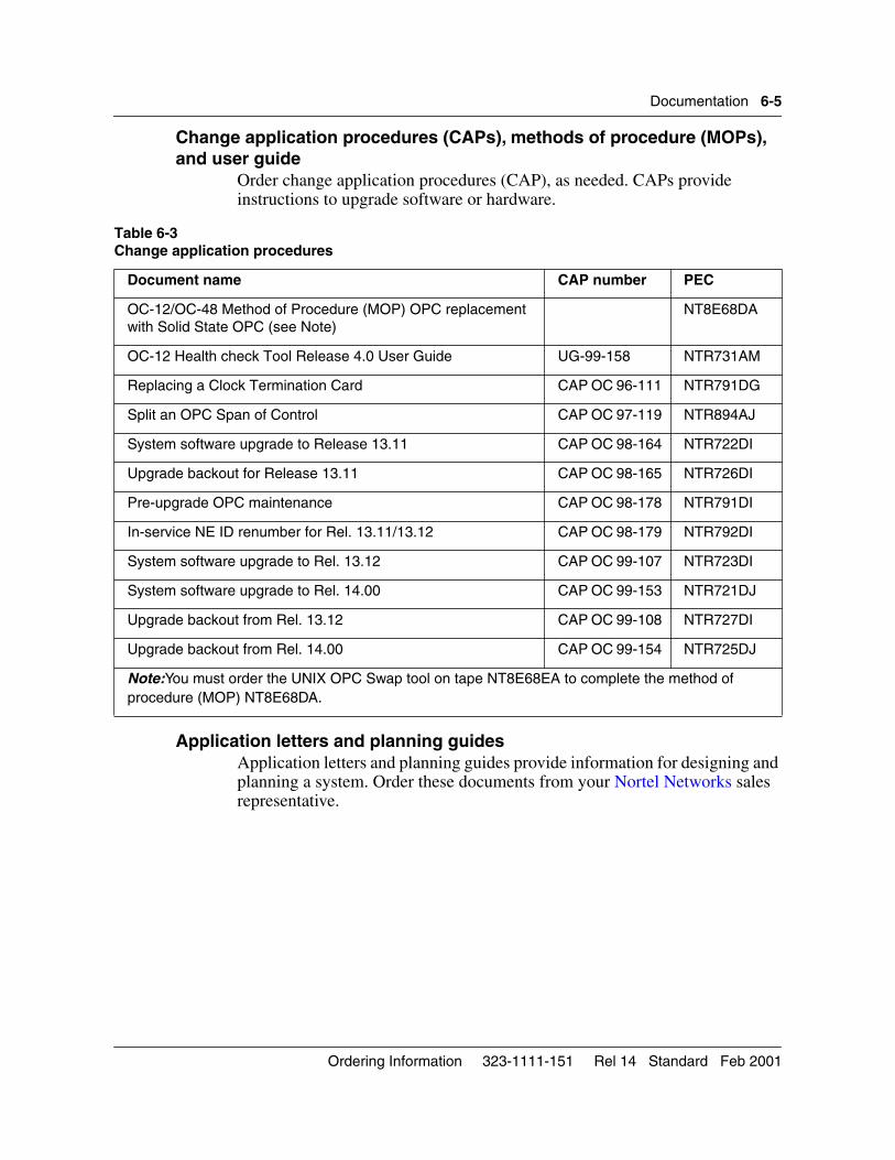
Documentation 6-5
Change application procedures (CAPs), methods of procedure (MOPs), and user guide
Order change application procedures (CAP), as needed. CAPs provide instructions to upgrade software or hardware.
Application letters and planning guidesApplication letters and planning guides provide information for designing and planning a system. Order these documents from your Nortel Networks sales representative.
Table 6-3Change application procedures
Document name CAP number PEC
OC-12/OC-48 Method of Procedure (MOP) OPC replacement with Solid State OPC (see Note)
NT8E68DA
OC-12 Health check Tool Release 4.0 User Guide UG-99-158 NTR731AM
Replacing a Clock Termination Card CAP OC 96-111 NTR791DG
Split an OPC Span of Control CAP OC 97-119 NTR894AJ
System software upgrade to Release 13.11 CAP OC 98-164 NTR722DI
Upgrade backout for Release 13.11 CAP OC 98-165 NTR726DI
Pre-upgrade OPC maintenance CAP OC 98-178 NTR791DI
In-service NE ID renumber for Rel. 13.11/13.12 CAP OC 98-179 NTR792DI
System software upgrade to Rel. 13.12 CAP OC 99-107 NTR723DI
System software upgrade to Rel. 14.00 CAP OC 99-153 NTR721DJ
Upgrade backout from Rel. 13.12 CAP OC 99-108 NTR727DI
Upgrade backout from Rel. 14.00 CAP OC 99-154 NTR725DJ
Note:You must order the UNIX OPC Swap tool on tape NT8E68EA to complete the method of procedure (MOP) NT8E68DA.
Ordering Information 323-1111-151 Rel 14 Standard Feb 2001
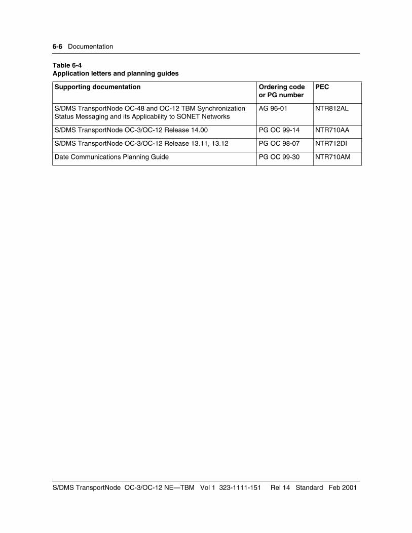
6-6 Documentation
Table 6-4 Application letters and planning guides
Supporting documentation Ordering code or PG number
PEC
S/DMS TransportNode OC-48 and OC-12 TBM Synchronization Status Messaging and its Applicability to SONET Networks
AG 96-01 NTR812AL
S/DMS TransportNode OC-3/OC-12 Release 14.00 PG OC 99-14 NTR710AA
S/DMS TransportNode OC-3/OC-12 Release 13.11, 13.12 PG OC 98-07 NTR712DI
Date Communications Planning Guide PG OC 99-30 NTR710AM
S/DMS TransportNode OC-3/OC-12 NE—TBM Vol 1 323-1111-151 Rel 14 Standard Feb 2001
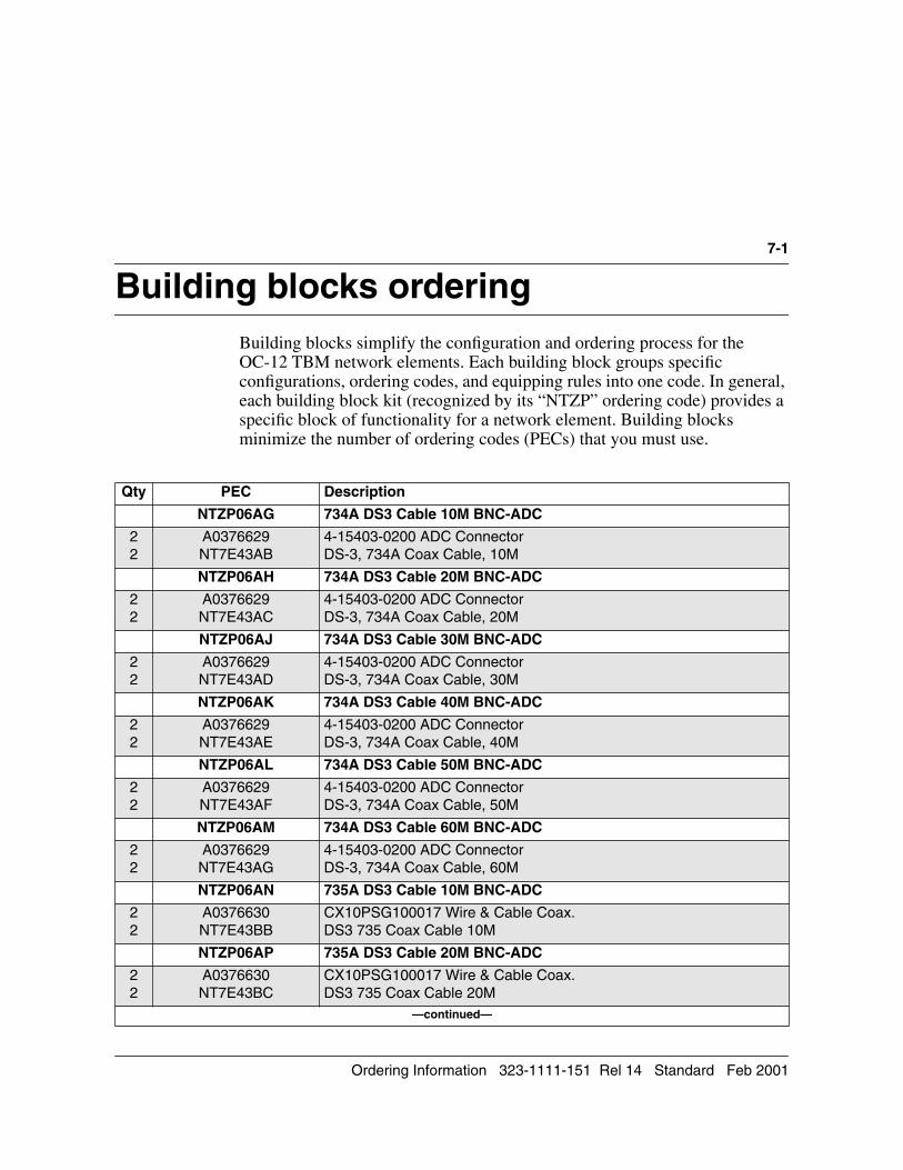
7-1
Building blocks ordering 7-Building blocks simplify the configuration and ordering process for the OC-12 TBM network elements. Each building block groups specific configurations, ordering codes, and equipping rules into one code. In general, each building block kit (recognized by its “NTZP” ordering code) provides a specific block of functionality for a network element. Building blocks minimize the number of ordering codes (PECs) that you must use.
Qty PEC Description
NTZP06AG 734A DS3 Cable 10M BNC-ADC
22
A0376629NT7E43AB
4-15403-0200 ADC ConnectorDS-3, 734A Coax Cable, 10M
NTZP06AH 734A DS3 Cable 20M BNC-ADC
22
A0376629NT7E43AC
4-15403-0200 ADC ConnectorDS-3, 734A Coax Cable, 20M
NTZP06AJ 734A DS3 Cable 30M BNC-ADC
22
A0376629NT7E43AD
4-15403-0200 ADC ConnectorDS-3, 734A Coax Cable, 30M
NTZP06AK 734A DS3 Cable 40M BNC-ADC
22
A0376629NT7E43AE
4-15403-0200 ADC ConnectorDS-3, 734A Coax Cable, 40M
NTZP06AL 734A DS3 Cable 50M BNC-ADC
22
A0376629NT7E43AF
4-15403-0200 ADC ConnectorDS-3, 734A Coax Cable, 50M
NTZP06AM 734A DS3 Cable 60M BNC-ADC
22
A0376629NT7E43AG
4-15403-0200 ADC ConnectorDS-3, 734A Coax Cable, 60M
NTZP06AN 735A DS3 Cable 10M BNC-ADC
22
A0376630NT7E43BB
CX10PSG100017 Wire & Cable Coax.DS3 735 Coax Cable 10M
NTZP06AP 735A DS3 Cable 20M BNC-ADC
22
A0376630NT7E43BC
CX10PSG100017 Wire & Cable Coax.DS3 735 Coax Cable 20M
—continued—
Ordering Information 323-1111-151 Rel 14 Standard Feb 2001
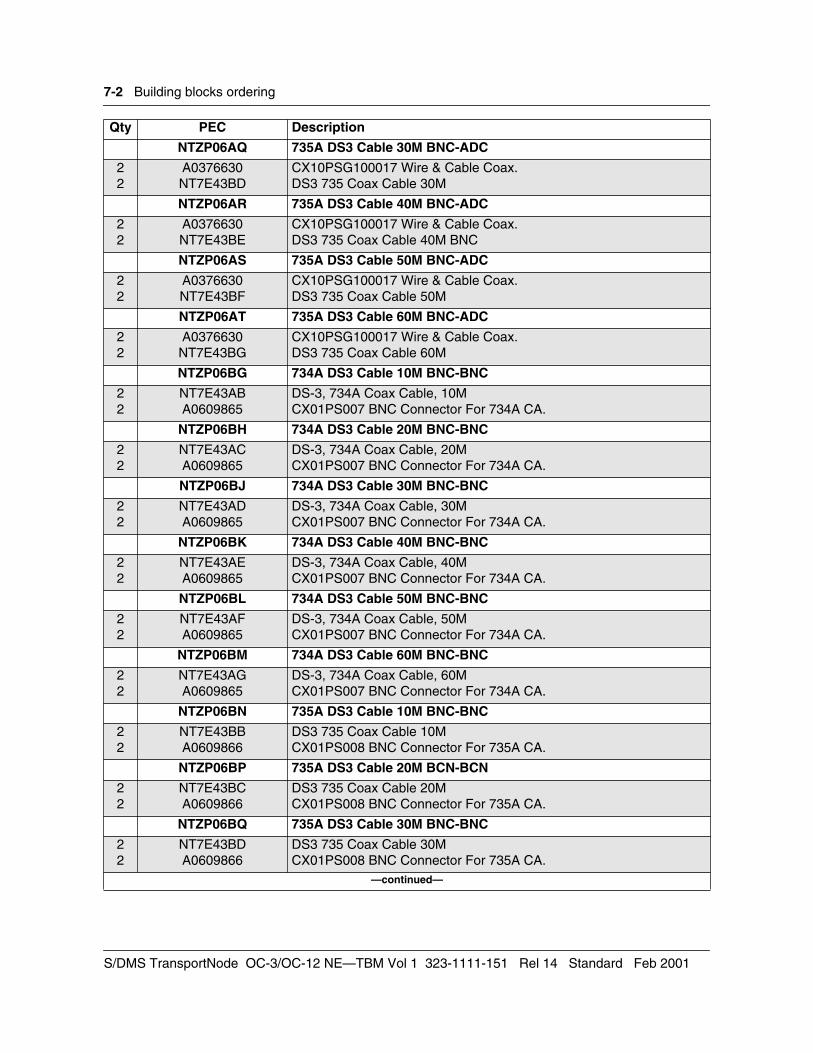
7-2 Building blocks ordering
NTZP06AQ 735A DS3 Cable 30M BNC-ADC
22
A0376630NT7E43BD
CX10PSG100017 Wire & Cable Coax.DS3 735 Coax Cable 30M
NTZP06AR 735A DS3 Cable 40M BNC-ADC
22
A0376630NT7E43BE
CX10PSG100017 Wire & Cable Coax.DS3 735 Coax Cable 40M BNC
NTZP06AS 735A DS3 Cable 50M BNC-ADC
22
A0376630NT7E43BF
CX10PSG100017 Wire & Cable Coax.DS3 735 Coax Cable 50M
NTZP06AT 735A DS3 Cable 60M BNC-ADC
22
A0376630NT7E43BG
CX10PSG100017 Wire & Cable Coax.DS3 735 Coax Cable 60M
NTZP06BG 734A DS3 Cable 10M BNC-BNC
22
NT7E43ABA0609865
DS-3, 734A Coax Cable, 10MCX01PS007 BNC Connector For 734A CA.
NTZP06BH 734A DS3 Cable 20M BNC-BNC
22
NT7E43ACA0609865
DS-3, 734A Coax Cable, 20MCX01PS007 BNC Connector For 734A CA.
NTZP06BJ 734A DS3 Cable 30M BNC-BNC
22
NT7E43ADA0609865
DS-3, 734A Coax Cable, 30MCX01PS007 BNC Connector For 734A CA.
NTZP06BK 734A DS3 Cable 40M BNC-BNC
22
NT7E43AEA0609865
DS-3, 734A Coax Cable, 40MCX01PS007 BNC Connector For 734A CA.
NTZP06BL 734A DS3 Cable 50M BNC-BNC
22
NT7E43AFA0609865
DS-3, 734A Coax Cable, 50MCX01PS007 BNC Connector For 734A CA.
NTZP06BM 734A DS3 Cable 60M BNC-BNC
22
NT7E43AGA0609865
DS-3, 734A Coax Cable, 60MCX01PS007 BNC Connector For 734A CA.
NTZP06BN 735A DS3 Cable 10M BNC-BNC
22
NT7E43BBA0609866
DS3 735 Coax Cable 10MCX01PS008 BNC Connector For 735A CA.
NTZP06BP 735A DS3 Cable 20M BCN-BCN
22
NT7E43BCA0609866
DS3 735 Coax Cable 20MCX01PS008 BNC Connector For 735A CA.
NTZP06BQ 735A DS3 Cable 30M BNC-BNC
22
NT7E43BDA0609866
DS3 735 Coax Cable 30MCX01PS008 BNC Connector For 735A CA.
—continued—
Qty PEC Description
S/DMS TransportNode OC-3/OC-12 NE—TBM Vol 1 323-1111-151 Rel 14 Standard Feb 2001
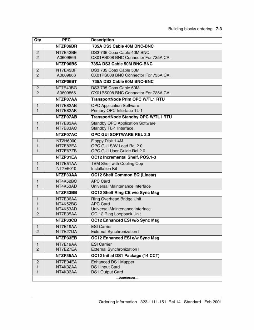
Building blocks ordering 7-3
NTZP06BR 735A DS3 Cable 40M BNC-BNC
22
NT7E43BEA0609866
DS3 735 Coax Cable 40M BNCCX01PS008 BNC Connector For 735A CA.
NTZP06BS 735A DS3 Cable 50M BNC-BNC
22
NT7E43BFA0609866
DS3 735 Coax Cable 50MCX01PS008 BNC Connector For 735A CA.
NTZP06BT 735A DS3 Cable 60M BNC-BNC
22
NT7E43BGA0609866
DS3 735 Coax Cable 60MCX01PS008 BNC Connector For 735A CA.
NTZP07AA TransportNode Prim OPC W/TL1 RTU
11
NT7E83ABNT7E82AK
OPC Application SoftwarePrimary OPC Interface TL-1
NTZP07AB TransportNode Standby OPC W/TL1 RTU
11
NT7E83AANT7E83AC
Standby OPC Application SoftwareStandby TL-1 Interface
NTZP07AC OPC GUI SOFTWARE REL 2.0
111
NT2H6000NT7E83EANT7E67ZB
Floppy Disk 1.4MOPC GUI S/W Load Rel 2.0OPC GUI User Guide Rel 2.0
NTZP31EA OC12 Incremental Shelf, POS.1-3
11
NT7E51AANT7E6010
TBM Shelf with Cooling CopInstallation Kit
NTZP33AA OC12 Shelf Common EQ (Linear)
11
NT4K52BCNT4K53AD
APC CardUniversal Maintenance Interface
NTZP33BB OC12 Shelf Ring CE w/o Sync Msg
1112
NT7E36AANT4K52BCNT4K53ADNT7E35AA
RIng Overhead Bridge UnitAPC CardUniversal Maintenance InterfaceOC-12 Ring Loopback Unit
NTZP33CB OC12 Enhanced ESI w/o Sync Msg
12
NT7E19AANT7E27DA
ESI CarrierExternal Synchronization I
NTZP33EB OC12 Enhanced ESI e/w Sync Msg
12
NT7E19AANT7E27EA
ESI CarrierExternal Synchronization I
NTZP35AA OC12 Initial DS1 Package (14 CCT)
211
NT7E04EANT4K32AANT4K33AA
Enhanced DS1 MapperDS1 Input CardDS1 Output Card
—continued—
Qty PEC Description
Ordering Information 323-1111-151 Rel 14 Standard Feb 2001
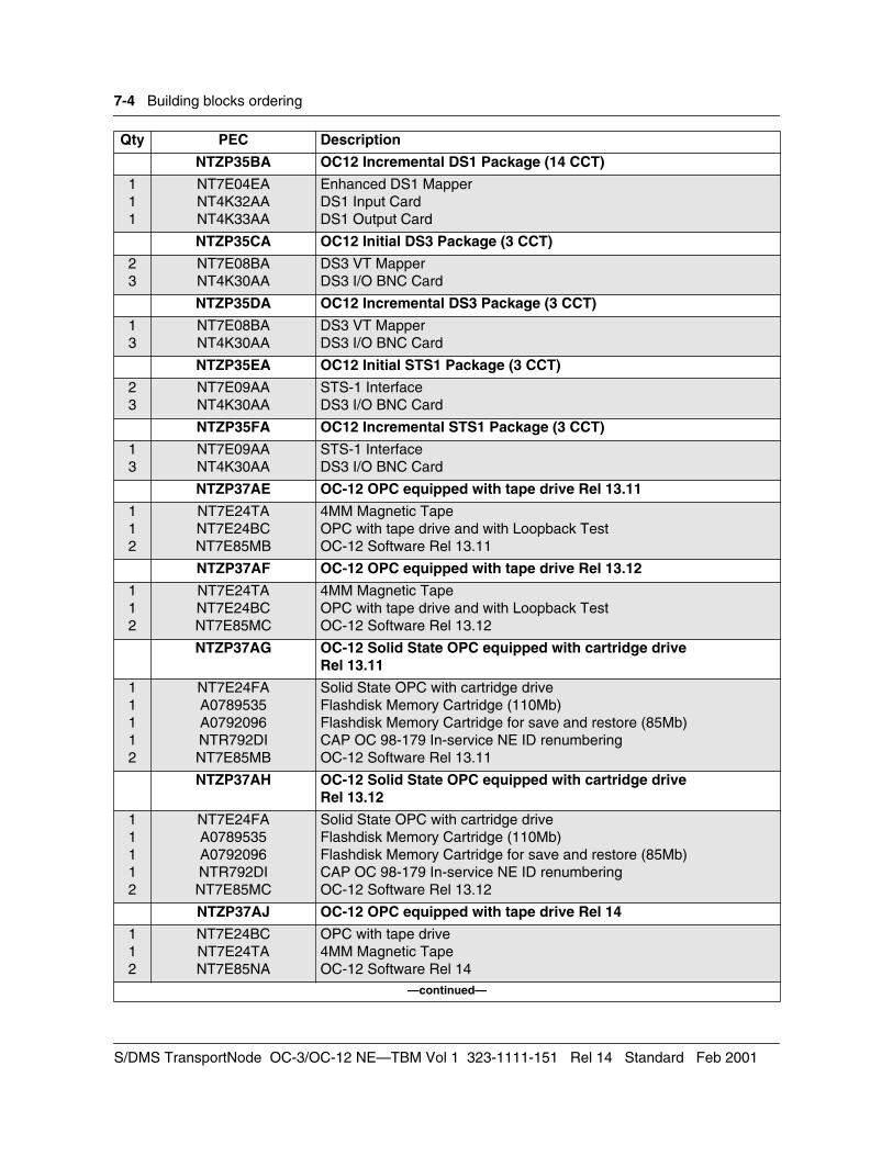
7-4 Building blocks ordering
NTZP35BA OC12 Incremental DS1 Package (14 CCT)
111
NT7E04EANT4K32AANT4K33AA
Enhanced DS1 MapperDS1 Input CardDS1 Output Card
NTZP35CA OC12 Initial DS3 Package (3 CCT)
23
NT7E08BANT4K30AA
DS3 VT MapperDS3 I/O BNC Card
NTZP35DA OC12 Incremental DS3 Package (3 CCT)
13
NT7E08BANT4K30AA
DS3 VT MapperDS3 I/O BNC Card
NTZP35EA OC12 Initial STS1 Package (3 CCT)
23
NT7E09AANT4K30AA
STS-1 InterfaceDS3 I/O BNC Card
NTZP35FA OC12 Incremental STS1 Package (3 CCT)
13
NT7E09AANT4K30AA
STS-1 InterfaceDS3 I/O BNC Card
NTZP37AE OC-12 OPC equipped with tape drive Rel 13.11
112
NT7E24TANT7E24BCNT7E85MB
4MM Magnetic TapeOPC with tape drive and with Loopback TestOC-12 Software Rel 13.11
NTZP37AF OC-12 OPC equipped with tape drive Rel 13.12
112
NT7E24TANT7E24BCNT7E85MC
4MM Magnetic TapeOPC with tape drive and with Loopback TestOC-12 Software Rel 13.12
NTZP37AG OC-12 Solid State OPC equipped with cartridge drive Rel 13.11
11112
NT7E24FAA0789535A0792096NTR792DINT7E85MB
Solid State OPC with cartridge driveFlashdisk Memory Cartridge (110Mb)Flashdisk Memory Cartridge for save and restore (85Mb)CAP OC 98-179 In-service NE ID renumberingOC-12 Software Rel 13.11
NTZP37AH OC-12 Solid State OPC equipped with cartridge drive Rel 13.12
11112
NT7E24FAA0789535A0792096NTR792DINT7E85MC
Solid State OPC with cartridge driveFlashdisk Memory Cartridge (110Mb)Flashdisk Memory Cartridge for save and restore (85Mb)CAP OC 98-179 In-service NE ID renumberingOC-12 Software Rel 13.12
NTZP37AJ OC-12 OPC equipped with tape drive Rel 14
112
NT7E24BCNT7E24TANT7E85NA
OPC with tape drive4MM Magnetic TapeOC-12 Software Rel 14
—continued—
Qty PEC Description
S/DMS TransportNode OC-3/OC-12 NE—TBM Vol 1 323-1111-151 Rel 14 Standard Feb 2001
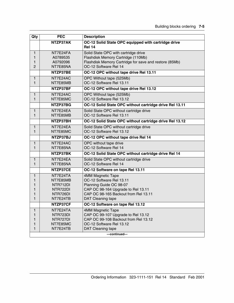
Building blocks ordering 7-5
NTZP37AK OC-12 Solid State OPC equipped with cartridge driveRel 14
1112
NT7E24FAA0789535A0792096NT7E85NA
Solid State OPC with cartridge driveFlashdisk Memory Cartridge (110Mb)Flashdisk Memory Cartridge for save and restore (85Mb)OC-12 Software Rel 14
NTZP37BE OC-12 OPC without tape drive Rel 13.11
11
NT7E24ACNT7E85MB
OPC Without tape (525Mb)OC-12 Software Rel 13.11
NTZP37BF OC-12 OPC without tape drive Rel 13.12
11
NT7E24ACNT7E85MC
OPC Without tape (525Mb)OC-12 Software Rel 13.12
NTZP37BG OC-12 Solid State OPC without cartridge drive Rel 13.11
11
NT7E24EANT7E85MB
Solid State OPC without cartridge driveOC-12 Software Rel 13.11
NTZP37BH OC-12 Solid State OPC without cartridge drive Rel 13.12
11
NT7E24EANT7E85MC
Solid State OPC without cartridge driveOC-12 Software Rel 13.12
NTZP37BJ OC-12 OPC without tape drive Rel 14
11
NT7E24ACNT7E85NA
OPC without tape driveOC-12 Software Rel 14
NTZP37BK OC-12 Solid State OPC without cartridge drive Rel 14
11
NT7E24EANT7E85NA
Solid State OPC without cartridge driveOC-12 Software Rel 14
NTZP37CE OC-12 Software on tape Rel 13.11
111111
NT7E24TANT7E85MBNTR712DINTR722DINTR726DINT7E24TB
4MM Magnetic TapeOC-12 Software Rel 13.11Planning Guide OC 98-07CAP OC 98-164 Upgrade to Rel 13.11CAP OC 98-165 Backout from Rel 13.11DAT Cleaning tape
NTZP37CF OC-12 Software on tape Rel 13.12
11111
NT7E24TANTR723DINTR727DINT7E85MCNT7E24TB
4MM Magnetic Tape CAP OC 99-107 Upgrade to Rel 13.12CAP OC 99-108 Backout from Rel 13.12OC-12 Software Rel 13.12DAT Cleaning tape
—continued—
Qty PEC Description
Ordering Information 323-1111-151 Rel 14 Standard Feb 2001
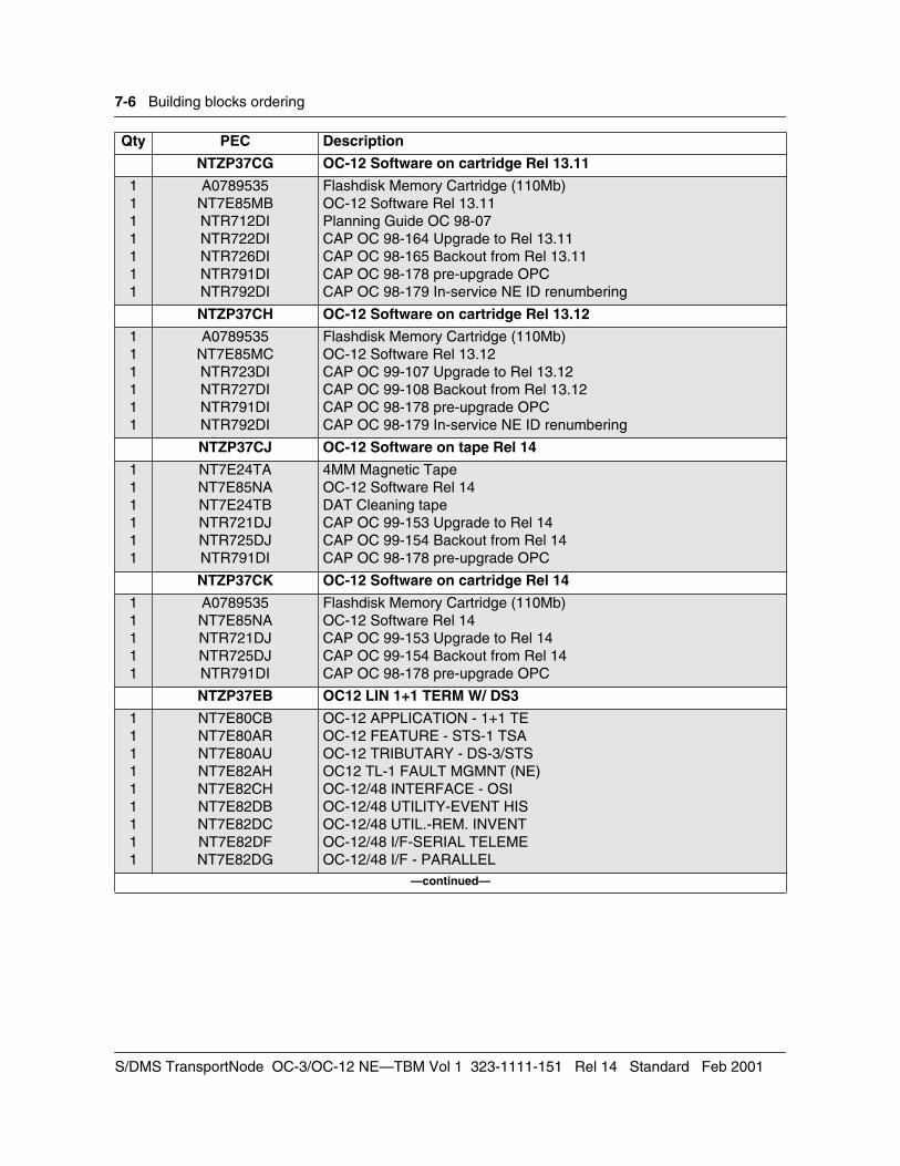
7-6 Building blocks ordering
NTZP37CG OC-12 Software on cartridge Rel 13.11
1111111
A0789535NT7E85MBNTR712DINTR722DINTR726DINTR791DINTR792DI
Flashdisk Memory Cartridge (110Mb)OC-12 Software Rel 13.11Planning Guide OC 98-07CAP OC 98-164 Upgrade to Rel 13.11CAP OC 98-165 Backout from Rel 13.11CAP OC 98-178 pre-upgrade OPCCAP OC 98-179 In-service NE ID renumbering
NTZP37CH OC-12 Software on cartridge Rel 13.12
111111
A0789535NT7E85MCNTR723DINTR727DINTR791DINTR792DI
Flashdisk Memory Cartridge (110Mb)OC-12 Software Rel 13.12CAP OC 99-107 Upgrade to Rel 13.12CAP OC 99-108 Backout from Rel 13.12CAP OC 98-178 pre-upgrade OPCCAP OC 98-179 In-service NE ID renumbering
NTZP37CJ OC-12 Software on tape Rel 14
111111
NT7E24TANT7E85NANT7E24TBNTR721DJNTR725DJNTR791DI
4MM Magnetic TapeOC-12 Software Rel 14DAT Cleaning tapeCAP OC 99-153 Upgrade to Rel 14CAP OC 99-154 Backout from Rel 14CAP OC 98-178 pre-upgrade OPC
NTZP37CK OC-12 Software on cartridge Rel 14
11111
A0789535NT7E85NANTR721DJNTR725DJNTR791DI
Flashdisk Memory Cartridge (110Mb)OC-12 Software Rel 14CAP OC 99-153 Upgrade to Rel 14CAP OC 99-154 Backout from Rel 14CAP OC 98-178 pre-upgrade OPC
NTZP37EB OC12 LIN 1+1 TERM W/ DS3
111111111
NT7E80CBNT7E80ARNT7E80AUNT7E82AHNT7E82CHNT7E82DBNT7E82DCNT7E82DFNT7E82DG
OC-12 APPLICATION - 1+1 TEOC-12 FEATURE - STS-1 TSAOC-12 TRIBUTARY - DS-3/STSOC12 TL-1 FAULT MGMNT (NE)OC-12/48 INTERFACE - OSIOC-12/48 UTILITY-EVENT HISOC-12/48 UTIL.-REM. INVENTOC-12/48 I/F-SERIAL TELEMEOC-12/48 I/F - PARALLEL
—continued—
Qty PEC Description
S/DMS TransportNode OC-3/OC-12 NE—TBM Vol 1 323-1111-151 Rel 14 Standard Feb 2001
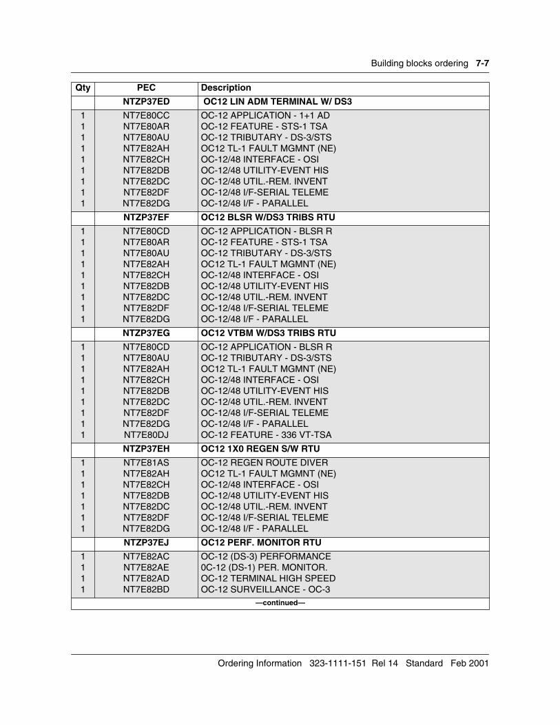
Building blocks ordering 7-7
NTZP37ED OC12 LIN ADM TERMINAL W/ DS3
111111111
NT7E80CCNT7E80ARNT7E80AUNT7E82AHNT7E82CHNT7E82DBNT7E82DCNT7E82DFNT7E82DG
OC-12 APPLICATION - 1+1 ADOC-12 FEATURE - STS-1 TSAOC-12 TRIBUTARY - DS-3/STSOC12 TL-1 FAULT MGMNT (NE)OC-12/48 INTERFACE - OSIOC-12/48 UTILITY-EVENT HISOC-12/48 UTIL.-REM. INVENTOC-12/48 I/F-SERIAL TELEMEOC-12/48 I/F - PARALLEL
NTZP37EF OC12 BLSR W/DS3 TRIBS RTU
111111111
NT7E80CDNT7E80ARNT7E80AUNT7E82AHNT7E82CHNT7E82DBNT7E82DCNT7E82DFNT7E82DG
OC-12 APPLICATION - BLSR ROC-12 FEATURE - STS-1 TSAOC-12 TRIBUTARY - DS-3/STSOC12 TL-1 FAULT MGMNT (NE)OC-12/48 INTERFACE - OSIOC-12/48 UTILITY-EVENT HISOC-12/48 UTIL.-REM. INVENTOC-12/48 I/F-SERIAL TELEMEOC-12/48 I/F - PARALLEL
NTZP37EG OC12 VTBM W/DS3 TRIBS RTU
111111111
NT7E80CDNT7E80AUNT7E82AHNT7E82CHNT7E82DBNT7E82DCNT7E82DFNT7E82DGNT7E80DJ
OC-12 APPLICATION - BLSR ROC-12 TRIBUTARY - DS-3/STSOC12 TL-1 FAULT MGMNT (NE)OC-12/48 INTERFACE - OSIOC-12/48 UTILITY-EVENT HISOC-12/48 UTIL.-REM. INVENTOC-12/48 I/F-SERIAL TELEMEOC-12/48 I/F - PARALLELOC-12 FEATURE - 336 VT-TSA
NTZP37EH OC12 1X0 REGEN S/W RTU
1111111
NT7E81ASNT7E82AHNT7E82CHNT7E82DBNT7E82DCNT7E82DFNT7E82DG
OC-12 REGEN ROUTE DIVEROC12 TL-1 FAULT MGMNT (NE)OC-12/48 INTERFACE - OSIOC-12/48 UTILITY-EVENT HISOC-12/48 UTIL.-REM. INVENTOC-12/48 I/F-SERIAL TELEMEOC-12/48 I/F - PARALLEL
NTZP37EJ OC12 PERF. MONITOR RTU
1111
NT7E82ACNT7E82AENT7E82ADNT7E82BD
OC-12 (DS-3) PERFORMANCE0C-12 (DS-1) PER. MONITOR.OC-12 TERMINAL HIGH SPEEDOC-12 SURVEILLANCE - OC-3
—continued—
Qty PEC Description
Ordering Information 323-1111-151 Rel 14 Standard Feb 2001
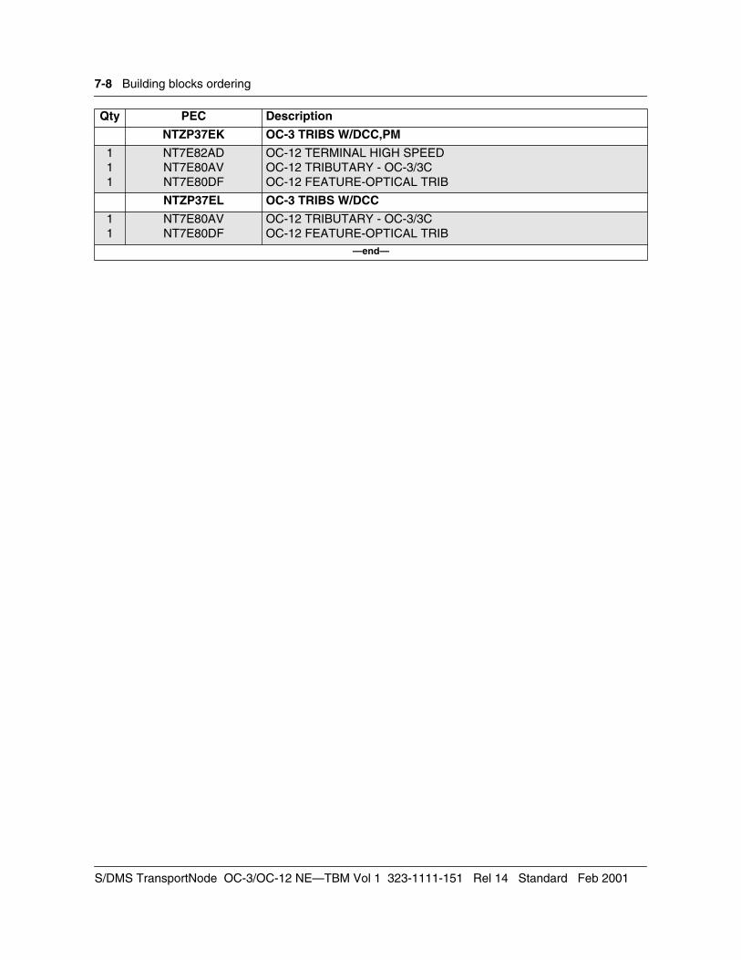
7-8 Building blocks ordering
NTZP37EK OC-3 TRIBS W/DCC,PM
111
NT7E82ADNT7E80AVNT7E80DF
OC-12 TERMINAL HIGH SPEEDOC-12 TRIBUTARY - OC-3/3COC-12 FEATURE-OPTICAL TRIB
NTZP37EL OC-3 TRIBS W/DCC
11
NT7E80AVNT7E80DF
OC-12 TRIBUTARY - OC-3/3COC-12 FEATURE-OPTICAL TRIB
—end—
Qty PEC Description
S/DMS TransportNode OC-3/OC-12 NE—TBM Vol 1 323-1111-151 Rel 14 Standard Feb 2001
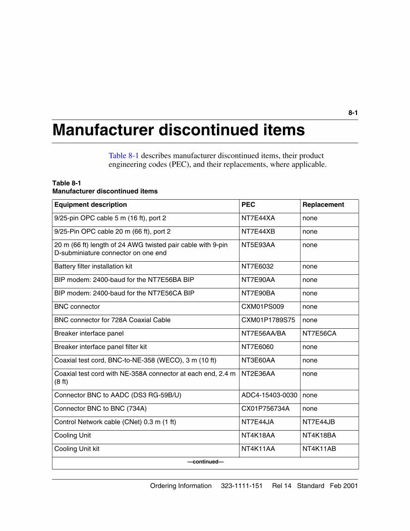
8-1
Manufacturer discontinued items 8-Table 8-1 describes manufacturer discontinued items, their product engineering codes (PEC), and their replacements, where applicable.
Table 8-1 Manufacturer discontinued items
Equipment description PEC Replacement
9/25-pin OPC cable 5 m (16 ft), port 2 NT7E44XA none
9/25-Pin OPC cable 20 m (66 ft), port 2 NT7E44XB none
20 m (66 ft) length of 24 AWG twisted pair cable with 9-pin D-subminiature connector on one end
NT5E93AA none
Battery filter installation kit NT7E6032 none
BIP modem: 2400-baud for the NT7E56BA BIP NT7E90AA none
BIP modem: 2400-baud for the NT7E56CA BIP NT7E90BA none
BNC connector CXM01PS009 none
BNC connector for 728A Coaxial Cable CXM01P1789S75 none
Breaker interface panel NT7E56AA/BA NT7E56CA
Breaker interface panel filter kit NT7E6060 none
Coaxial test cord, BNC-to-NE-358 (WECO), 3 m (10 ft) NT3E60AA none
Coaxial test cord with NE-358A connector at each end, 2.4 m (8 ft)
NT2E36AA none
Connector BNC to AADC (DS3 RG-59B/U) ADC4-15403-0030 none
Connector BNC to BNC (734A) CX01P756734A none
Control Network cable (CNet) 0.3 m (1 ft) NT7E44JA NT7E44JB
Cooling Unit NT4K18AA NT4K18BA
Cooling Unit kit NT4K11AA NT4K11AB
—continued—
Ordering Information 323-1111-151 Rel 14 Standard Feb 2001
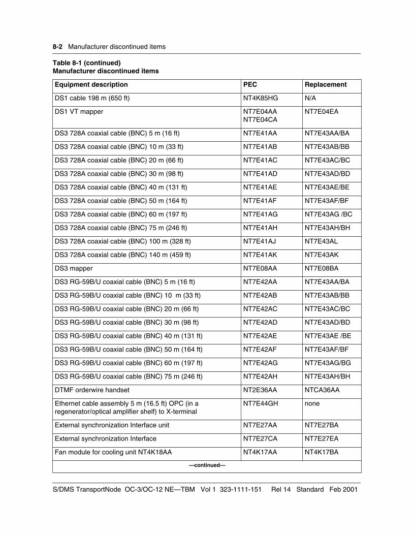
8-2 Manufacturer discontinued items
DS1 cable 198 m (650 ft) NT4K85HG N/A
DS1 VT mapper NT7E04AANT7E04CA
NT7E04EA
DS3 728A coaxial cable (BNC) 5 m (16 ft) NT7E41AA NT7E43AA/BA
DS3 728A coaxial cable (BNC) 10 m (33 ft) NT7E41AB NT7E43AB/BB
DS3 728A coaxial cable (BNC) 20 m (66 ft) NT7E41AC NT7E43AC/BC
DS3 728A coaxial cable (BNC) 30 m (98 ft) NT7E41AD NT7E43AD/BD
DS3 728A coaxial cable (BNC) 40 m (131 ft) NT7E41AE NT7E43AE/BE
DS3 728A coaxial cable (BNC) 50 m (164 ft) NT7E41AF NT7E43AF/BF
DS3 728A coaxial cable (BNC) 60 m (197 ft) NT7E41AG NT7E43AG /BC
DS3 728A coaxial cable (BNC) 75 m (246 ft) NT7E41AH NT7E43AH/BH
DS3 728A coaxial cable (BNC) 100 m (328 ft) NT7E41AJ NT7E43AL
DS3 728A coaxial cable (BNC) 140 m (459 ft) NT7E41AK NT7E43AK
DS3 mapper NT7E08AA NT7E08BA
DS3 RG-59B/U coaxial cable (BNC) 5 m (16 ft) NT7E42AA NT7E43AA/BA
DS3 RG-59B/U coaxial cable (BNC) 10 m (33 ft) NT7E42AB NT7E43AB/BB
DS3 RG-59B/U coaxial cable (BNC) 20 m (66 ft) NT7E42AC NT7E43AC/BC
DS3 RG-59B/U coaxial cable (BNC) 30 m (98 ft) NT7E42AD NT7E43AD/BD
DS3 RG-59B/U coaxial cable (BNC) 40 m (131 ft) NT7E42AE NT7E43AE /BE
DS3 RG-59B/U coaxial cable (BNC) 50 m (164 ft) NT7E42AF NT7E43AF/BF
DS3 RG-59B/U coaxial cable (BNC) 60 m (197 ft) NT7E42AG NT7E43AG/BG
DS3 RG-59B/U coaxial cable (BNC) 75 m (246 ft) NT7E42AH NT7E43AH/BH
DTMF orderwire handset NT2E36AA NTCA36AA
Ethernet cable assembly 5 m (16.5 ft) OPC (in a regenerator/optical amplifier shelf) to X-terminal
NT7E44GH none
External synchronization Interface unit NT7E27AA NT7E27BA
External synchronization Interface NT7E27CA NT7E27EA
Fan module for cooling unit NT4K18AA NT4K17AA NT4K17BA
—continued—
Table 8-1 (continued)Manufacturer discontinued items
Equipment description PEC Replacement
S/DMS TransportNode OC-3/OC-12 NE—TBM Vol 1 323-1111-151 Rel 14 Standard Feb 2001
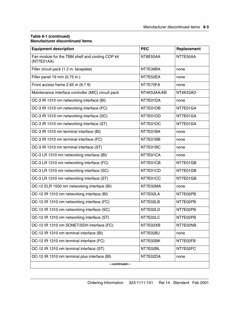
Manufacturer discontinued items 8-3
Fan module for the TBM shelf and cooling COP kit (NT7E51AA)
NT8E55AA NT7E55AA
Filler circuit pack (1.2 in. faceplate) NT7E39BA none
Filler panel 19 mm (0.75 in.) NT7E52EA none
Front access frame 2.65 m (8.7 ft) NT7E70FA none
Maintenance interface controller (MIC) circuit pack NT4K53AA/AB NT4K53AD
OC-3 IR 1310 nm networking interface (BI) NT7E01DA none
OC-3 IR 1310 nm networking interface (FC) NT7E01DB NT7E01GA
OC-3 IR 1310 nm networking interface (SC) NT7E01DD NT7E01GA
OC-3 IR 1310 nm networking interface (ST) NT7E01DC NT7E01GA
OC-3 IR 1310 nm terminal interface (BI) NT7E01BA none
OC-3 IR 1310 nm terminal interface (FC) NT7E01BB none
OC-3 IR 1310 nm terminal interface (ST) NT7E01BC none
OC-3 LR 1310 nm networking interface (BI) NT7E01CA none
OC-3 LR 1310 nm networking interface (FC) NT7E01CB NT7E01GB
OC-3 LR 1310 nm networking interface (SC) NT7E01CD NT7E01GB
OC-3 LR 1310 nm networking interface (ST) NT7E01CC NT7E01GB
OC-12 ELR 1550 nm networking interface (BI) NT7E02MA none
OC-12 IR 1310 nm networking interface (BI) NT7E02LA NT7E05PB
OC-12 IR 1310 nm networking interface (FC) NT7E02LB NT7E02PB
OC-12 IR 1310 nm networking interface (SC) NT7E02LD NT7E02PB
OC-12 IR 1310 nm networking interface (ST) NT7E02LC NT7E02PB
OC-12 IR 1310 nm SONET/SDH interface (FC) NT7E02XB NT7E02NB
OC-12 IR 1310 nm terminal interface (BI) NT7E02BJ none
OC-12 IR 1310 nm terminal interface (FC) NT7E02BK NT7E02FB
OC-12 IR 1310 nm terminal interface (ST) NT7E02BL NT7E02FC
OC-12 IR 1310 nm terminal plus interface (BI) NT7E02DA none
—continued—
Table 8-1 (continued)Manufacturer discontinued items
Equipment description PEC Replacement
Ordering Information 323-1111-151 Rel 14 Standard Feb 2001
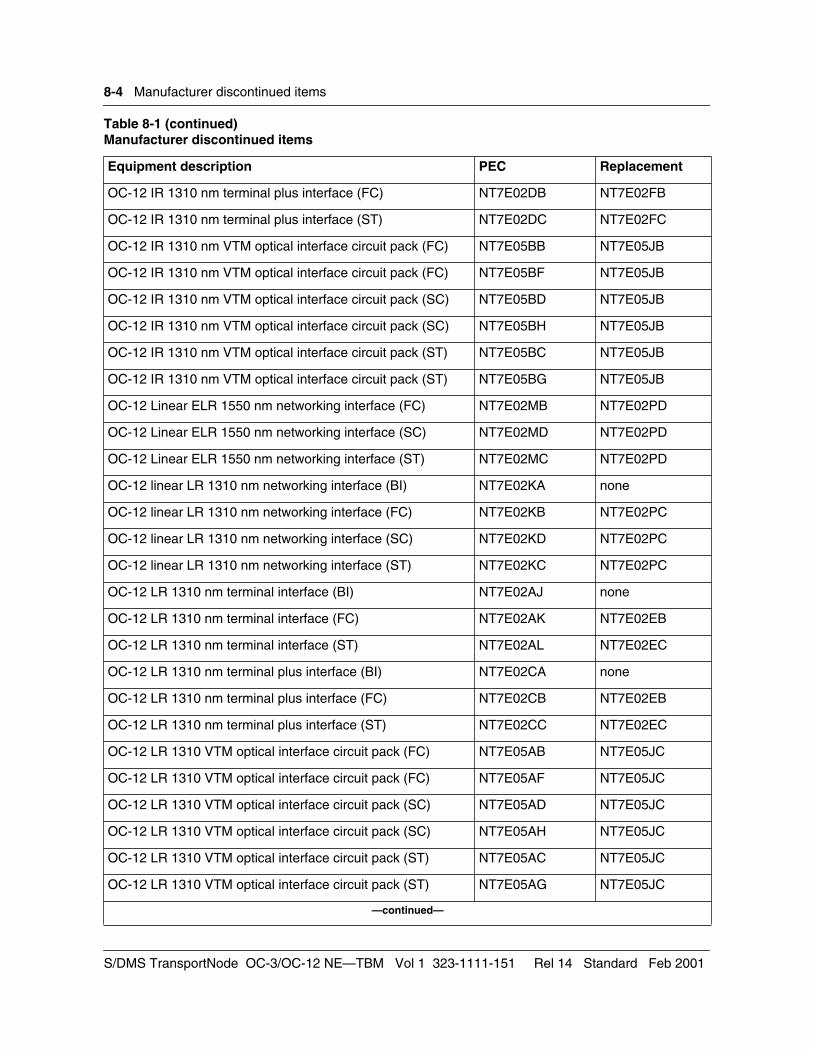
8-4 Manufacturer discontinued items
OC-12 IR 1310 nm terminal plus interface (FC) NT7E02DB NT7E02FB
OC-12 IR 1310 nm terminal plus interface (ST) NT7E02DC NT7E02FC
OC-12 IR 1310 nm VTM optical interface circuit pack (FC) NT7E05BB NT7E05JB
OC-12 IR 1310 nm VTM optical interface circuit pack (FC) NT7E05BF NT7E05JB
OC-12 IR 1310 nm VTM optical interface circuit pack (SC) NT7E05BD NT7E05JB
OC-12 IR 1310 nm VTM optical interface circuit pack (SC) NT7E05BH NT7E05JB
OC-12 IR 1310 nm VTM optical interface circuit pack (ST) NT7E05BC NT7E05JB
OC-12 IR 1310 nm VTM optical interface circuit pack (ST) NT7E05BG NT7E05JB
OC-12 Linear ELR 1550 nm networking interface (FC) NT7E02MB NT7E02PD
OC-12 Linear ELR 1550 nm networking interface (SC) NT7E02MD NT7E02PD
OC-12 Linear ELR 1550 nm networking interface (ST) NT7E02MC NT7E02PD
OC-12 linear LR 1310 nm networking interface (BI) NT7E02KA none
OC-12 linear LR 1310 nm networking interface (FC) NT7E02KB NT7E02PC
OC-12 linear LR 1310 nm networking interface (SC) NT7E02KD NT7E02PC
OC-12 linear LR 1310 nm networking interface (ST) NT7E02KC NT7E02PC
OC-12 LR 1310 nm terminal interface (BI) NT7E02AJ none
OC-12 LR 1310 nm terminal interface (FC) NT7E02AK NT7E02EB
OC-12 LR 1310 nm terminal interface (ST) NT7E02AL NT7E02EC
OC-12 LR 1310 nm terminal plus interface (BI) NT7E02CA none
OC-12 LR 1310 nm terminal plus interface (FC) NT7E02CB NT7E02EB
OC-12 LR 1310 nm terminal plus interface (ST) NT7E02CC NT7E02EC
OC-12 LR 1310 VTM optical interface circuit pack (FC) NT7E05AB NT7E05JC
OC-12 LR 1310 VTM optical interface circuit pack (FC) NT7E05AF NT7E05JC
OC-12 LR 1310 VTM optical interface circuit pack (SC) NT7E05AD NT7E05JC
OC-12 LR 1310 VTM optical interface circuit pack (SC) NT7E05AH NT7E05JC
OC-12 LR 1310 VTM optical interface circuit pack (ST) NT7E05AC NT7E05JC
OC-12 LR 1310 VTM optical interface circuit pack (ST) NT7E05AG NT7E05JC
—continued—
Table 8-1 (continued)Manufacturer discontinued items
Equipment description PEC Replacement
S/DMS TransportNode OC-3/OC-12 NE—TBM Vol 1 323-1111-151 Rel 14 Standard Feb 2001
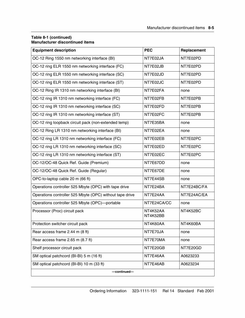
Manufacturer discontinued items 8-5
OC-12 Ring 1550 nm networking interface (BI) NT7E02JA NT7E02PD
OC-12 ring ELR 1550 nm networking interface (FC) NT7E02JB NT7E02PD
OC-12 ring ELR 1550 nm networking interface (SC) NT7E02JD NT7E02PD
OC-12 ring ELR 1550 nm networking interface (ST) NT7E02JC NT7E02PD
OC-12 Ring IR 1310 nm networking interface (BI) NT7E02FA none
OC-12 ring IR 1310 nm networking interface (FC) NT7E02FB NT7E02PB
OC-12 ring IR 1310 nm networking interface (SC) NT7E02FD NT7E02PB
OC-12 ring IR 1310 nm networking interface (ST) NT7E02FC NT7E02PB
OC-12 ring loopback circuit pack (non-extended temp) NT7E35BA none
OC-12 Ring LR 1310 nm networking interface (BI) NT7E02EA none
OC-12 ring LR 1310 nm networking interface (FC) NT7E02EB NT7E02PC
OC-12 ring LR 1310 nm networking interface (SC) NT7E02ED NT7E02PC
OC-12 ring LR 1310 nm networking interface (ST) NT7E02EC NT7E02PC
OC-12/OC-48 Quick Ref. Guide (Premium) NT7E67DD none
OC-12/OC-48 Quick Ref. Guide (Regular) NT7E67DE none
OPC-to-laptop cable 20 m (66 ft) NT7E44SB none
Operations controller 525 Mbyte (OPC) with tape drive NT7E24BA NT7E24BC/FA
Operations controller 525 Mbyte (OPC) without tape drive NT7E24AA NT7E24AC/EA
Operations controller 525 Mbyte (OPC)—portable NT7E24CA/CC none
Processor (Proc) circuit pack NT4K52AANT4K52BB
NT4K52BC
Protection switcher circuit pack NT4K60AA NT4K60BA
Rear access frame 2.44 m (8 ft) NT7E70JA none
Rear access frame 2.65 m (8.7 ft) NT7E70MA none
Shelf processor circuit pack NT7E20GB NT7E20GD
SM optical patchcord (BI-BI) 5 m (16 ft) NT7E46AA A0623233
SM optical patchcord (BI-BI) 10 m (33 ft) NT7E46AB A0623234
—continued—
Table 8-1 (continued)Manufacturer discontinued items
Equipment description PEC Replacement
Ordering Information 323-1111-151 Rel 14 Standard Feb 2001
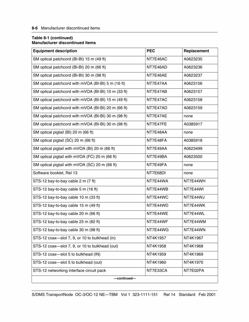
8-6 Manufacturer discontinued items
SM optical patchcord (BI-BI) 15 m (49 ft) NT7E46AC A0623235
SM optical patchcord (BI-BI) 20 m (66 ft) NT7E46AD A0623236
SM optical patchcord (BI-BI) 30 m (98 ft) NT7E46AE A0623237
SM optical patchcord with mVOA (BI-BI) 5 m (16 ft) NT7E47AA A0623156
SM optical patchcord with mVOA (BI-BI) 10 m (33 ft) NT7E47AB A0623157
SM optical patchcord with mVOA (BI-BI) 15 m (49 ft) NT7E47AC A0623158
SM optical patchcord with mVOA (BI-BI) 20 m (66 ft) NT7E47AD A0623159
SM optical patchcord with mVOA (BI-BI) 30 m (98 ft) NT7E47AE none
SM optical patchcord with mVOA (BI-BI) 30 m (98 ft) NT7E47FE A0385917
SM optical pigtail (BI) 20 m (66 ft) NT7E48AA none
SM optical pigtail (SC) 20 m (66 ft) NT7E48FA A0385918
SM optical pigtail with mVOA (BI) 20 m (66 ft) NT7E49AA A0623499
SM optical pigtail with mVOA (FC) 20 m (66 ft) NT7E49BA A0623500
SM optical pigtail with mVOA (SC) 20 m (66 ft) NT7E49FA none
Software booklet, Rel 13 NT7E68DI none
STS-12 bay-to-bay cable 2 m (7 ft) NT7E44WA NT7E44WH
STS-12 bay-to-bay cable 5 m (16 ft) NT7E44WB NT7E44WI
STS-12 bay-to-bay cable 10 m (33 ft) NT7E44WC NT7E44WJ
STS-12 bay-to-bay cable 15 m (49 ft) NT7E44WD NT7E44WK
STS-12 bay-to-bay cable 20 m (66 ft) NT7E44WE NT7E44WL
STS-12 bay-to-bay cable 25 m (82 ft) NT7E44WF NT7E44WM
STS-12 bay-to-bay cable 30 m (98 ft) NT7E44WG NT7E44WN
STS-12 coax—slot 7, 9, or 10 to bulkhead (in) NT4K1957 NT4K1967
STS-12 coax—slot 7, 9, or 10 to bulkhead (out) NT4K1958 NT4K1968
STS-12 coax—slot 5 to bulkhead (IN) NT4K1959 NT4K1969
STS-12 coax—slot 5 to bulkhead (out) NT4K1960 NT4K1970
STS-12 networking interface circuit pack NT7E33CA NT7E02PA
—continued—
Table 8-1 (continued)Manufacturer discontinued items
Equipment description PEC Replacement
S/DMS TransportNode OC-3/OC-12 NE—TBM Vol 1 323-1111-151 Rel 14 Standard Feb 2001
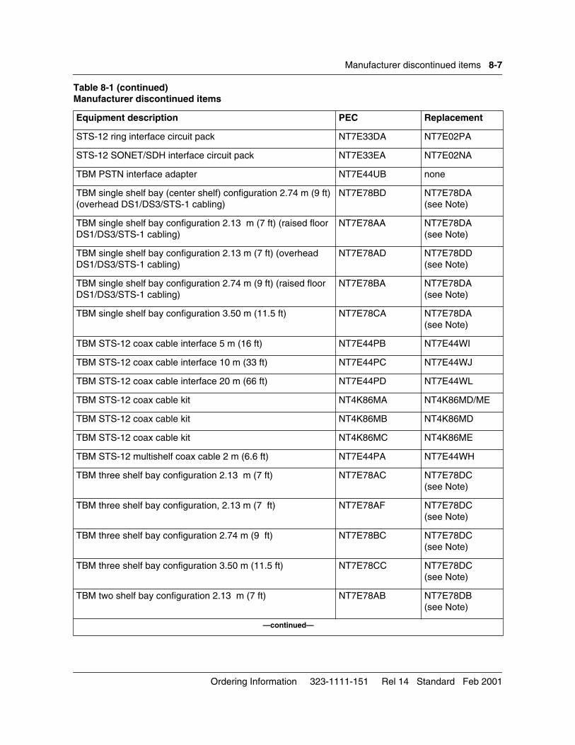
Manufacturer discontinued items 8-7
STS-12 ring interface circuit pack NT7E33DA NT7E02PA
STS-12 SONET/SDH interface circuit pack NT7E33EA NT7E02NA
TBM PSTN interface adapter NT7E44UB none
TBM single shelf bay (center shelf) configuration 2.74 m (9 ft) (overhead DS1/DS3/STS-1 cabling)
NT7E78BD NT7E78DA(see Note)
TBM single shelf bay configuration 2.13 m (7 ft) (raised floor DS1/DS3/STS-1 cabling)
NT7E78AA NT7E78DA(see Note)
TBM single shelf bay configuration 2.13 m (7 ft) (overhead DS1/DS3/STS-1 cabling)
NT7E78AD NT7E78DD(see Note)
TBM single shelf bay configuration 2.74 m (9 ft) (raised floor DS1/DS3/STS-1 cabling)
NT7E78BA NT7E78DA(see Note)
TBM single shelf bay configuration 3.50 m (11.5 ft) NT7E78CA NT7E78DA(see Note)
TBM STS-12 coax cable interface 5 m (16 ft) NT7E44PB NT7E44WI
TBM STS-12 coax cable interface 10 m (33 ft) NT7E44PC NT7E44WJ
TBM STS-12 coax cable interface 20 m (66 ft) NT7E44PD NT7E44WL
TBM STS-12 coax cable kit NT4K86MA NT4K86MD/ME
TBM STS-12 coax cable kit NT4K86MB NT4K86MD
TBM STS-12 coax cable kit NT4K86MC NT4K86ME
TBM STS-12 multishelf coax cable 2 m (6.6 ft) NT7E44PA NT7E44WH
TBM three shelf bay configuration 2.13 m (7 ft) NT7E78AC NT7E78DC(see Note)
TBM three shelf bay configuration, 2.13 m (7 ft) NT7E78AF NT7E78DC(see Note)
TBM three shelf bay configuration 2.74 m (9 ft) NT7E78BC NT7E78DC(see Note)
TBM three shelf bay configuration 3.50 m (11.5 ft) NT7E78CC NT7E78DC(see Note)
TBM two shelf bay configuration 2.13 m (7 ft) NT7E78AB NT7E78DB(see Note)
—continued—
Table 8-1 (continued)Manufacturer discontinued items
Equipment description PEC Replacement
Ordering Information 323-1111-151 Rel 14 Standard Feb 2001
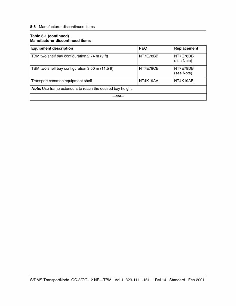
8-8 Manufacturer discontinued items
TBM two shelf bay configuration 2.74 m (9 ft) NT7E78BB NT7E78DB(see Note)
TBM two shelf bay configuration 3.50 m (11.5 ft) NT7E78CB NT7E78DB(see Note)
Transport common equipment shelf NT4K19AA NT4K19AB
Note: Use frame extenders to reach the desired bay height.
—end—
Table 8-1 (continued)Manufacturer discontinued items
Equipment description PEC Replacement
S/DMS TransportNode OC-3/OC-12 NE—TBM Vol 1 323-1111-151 Rel 14 Standard Feb 2001

SONET Transmission Products
S/DMS TransportNode OC-3/OC-12 NE—TBM Ordering Information
Copyright 1992–2001 Nortel Networks, All Rights Reserved
The information contained herein is the property of Nortel Networks and is strictly confidential. Except as expressly authorized in writing by Nortel Networks, the holder shall keep all information contained herein confidential, shall disclose it only to its employees with a need to know, and shall protect it, in whole or in part, from disclosure and dissemination to third parties with the same degree of care it uses to protect its own confidential information, but with no less than reasonable care. Except as expressly authorized in writing by Nortel Networks, the holder is granted no rights to use the information contained herein.
Nortel Networks and S/DMS TransportNode are trademarks of Nortel Networks. VT100 is a trademark of Digital Equipment Corporation. UNIX is a trademark of X/Open Company Ltd.
323-1111-151 Rel 14 StandardFebruary 2001Printed in Canada


![[NN40020-604] BCM50 Telset Administration Guidecleartelecommunications.com/documentation/Nortel/Nortel BCM-50... · BCM50 Telset Administration Guide Getting Help through a Nortel](https://img.pdfslide.us/doc/110x75/5b5ab0367f8b9ab8578c6436/nn40020-604-bcm50-telset-administration-guidecle-bcm-50-bcm50-telset-administration.jpg)