Embed Size (px)
Citation preview
1. Introduction
Grain refining may be obtained by introducing sub-mi-cron sized inclusions in the liquid steel that can act as het-erogeneous nucleation sites for different types of mi-crostructures during solidification. According to Grong etal.1) it is very important that a low misfit exist between theinclusion and the solidifying metal and that the inclusionsare thermodynamically stable.
This paper initially discusses disadvantages and advan-tages with adding future grain refiners in the ladle, tundishor mold. Based on this discussion it is seen that cloggingmay be a potential obstacle to be solved before grain refin-ing can be implemented in the industry. It is also, of course,known that nozzle blockage during continuous casting ofsteel is already a production problem today for commercialsteel grades. The clogging will lead to a decreased numberof heats that can be cast in a sequence. In some extremecases, it might even be impossible to cast a particular steelgrade using continuous casting due to severe problems withnozzle clogging. Instead, those particular steel grades willhave to be cast using ingot casting where nozzle sizes arebigger and deposition of inclusions are less problematic.Thus, the main focus in the paper is on the clogging phe-nomena.
In order to study how nozzle clogging can be avoided or
limited it is of importance to know more about the mecha-nisms. This presentation will highlight some ideas of howin-situ experiments, laboratory experiments, fluid-flowmodeling and thermodynamic calculations can be com-bined to increase the knowledge regarding nozzle cloggingphenomena.
2. Grain Refiner Additions
Studies have suggested that the size of potential grain re-finers should be of sub-micron levels.1,2) In addition,Kolbeinssen et al.3) has suggested that the number of grainrefiners per unit volume of steel needs to be a certainamount per volume. Thus, a big question that arises iswhere to add the grain refiners. In the continuous castingsteelmaking route the addition may be made either in theladle, tundish or mold while in the ingot casting steelmak-ing route in the ladle or the ingot mold. For both methods,the grain refiners should be evenly distributed in the steelmelt when the solidification of the metal starts during cast-ing.
In Table 1 some possible advantages and disadvantagesof adding grain refiners in the ladle, tundish or mold arelisted. During ladle treatment many refining operations arecarried out, which affects both the chemical equilibria andthe mass, heat and momentum transport in different parts of
ISIJ International, Vol. 46 (2006), No. 6, pp. 814–823
© 2006 ISIJ 814
Some Aspects on Grain Refining Additions with Focus on Clogging during Casting
Margareta ANDERSSON,1) Jesper APPELBERG,2) Anders TILLIANDER,1) Keiji NAKAJIMA,1)
Hiroyuki SHIBATA,3) Shin-ya KITAMURA,3) Lage JONSSON1) and Pär JÖNSSON1)
1) Division of Applied Process Metallurgy, KTH, 100 44 Stockholm, Sweden. 2) Outokumpu Stainless Avesta Works,774 80 Avesta, Sweden. 3) Kitamura Lab, Tohoku University, Katahira 2-1-1, Aoba-ku, Sendai, 980-8577 Japan.
(Received on December 28, 2005; accepted on February 28, 2006 )
Some ideas of how to study optimum conditions for implementation of grain refining in liquid steel pro-cessing with focus on how to avoid clogging are discussed. It is assumed that the inclusions most benefi-cial for grain refining are known from studies by physical metallurgists. The challenge for a process metallur-gist is how to provide a homogeneous distribution of grain refiners at the onset of solidification. Four differ-ent ways of providing information to succeed with this are discussed. Thermodynamic modeling can beused to predict what additions to make to create potential grain refiners, if relevant thermodynamic data isavailable. Mathematical fluid-flow modeling can be used to study where to add potential grain refiners. It isdiscussed that the tundish is the most appropriate reactor to add grain refiners, since enough time is givento a complete mixing of the grain refiner into the steel before the steel enters the mold. By using the scan-ning laser microscopy technique it is possible to study which potential grain refiners has the lowest attrac-tion forces between each other. This is important in order to minimise growth of inclusions when they col-lide during transport in the tundish, which can lead to the formation of larger inclusions that do not serve asuseful grain refiners. Finally, it is suggested that laboratory experiments are carried out in order to study thetendency for nozzle clogging, before the use of grain refiners is tested in industrial scale.
KEY WORDS: grain; clogging; inclusions; casting; thermodynamics; experiments; modeling.
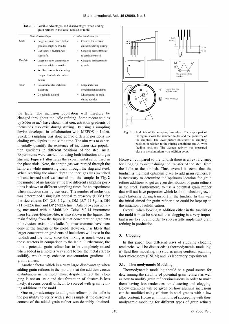
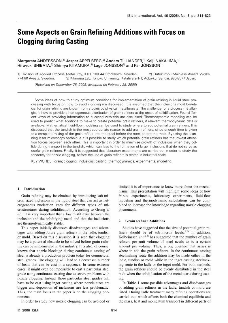
the ladle. The inclusion population will therefore bechanged throughout the ladle refining. Some recent studiesby Söder et al.4) have shown that concentration gradients ofinclusions also exist during stirring. By using a samplingdevise developed in collaboration with MEFOS in Luleå,Sweden, sampling was done at five different positions in-cluding two depths at the same time. The aim was to exper-imentally quantify the existence of inclusion size popula-tion gradients in different positions of the steel melt.Experiments were carried out using both induction and gasstirring. Figure 1 illustrates the experimental setup used inthe plant trials. Note, that argon gas was purged through thesamplers while immersing them through the slag and steel.When reaching the aimed depth the inert gas was switchedoff and instead steel was sucked into the sample. In Fig. 2the number of inclusions at the five different sampling posi-tions is shown at different sampling times for an experimentwhen induction stirring was used. The number of inclusionswas determined using light optical microscopy (LOM) forthe size classes DT (2.8–5.7 mm), DM (5.7–11.3 mm), DH(11.3–22.6 mm) and DP (�22.6 mm). Data of oxygen activi-ty, measured with a Multi-Lab Celox V2.14 instrumentfrom Heraeus-Electro-Nite, is also shown in the figure. Themain finding from the figure is that concentration gradientsof inclusions exist in the ladle. No measurements have beendone in the tundish or the mold. However, it is likely thatlarger concentration gradients of inclusions will exist in thetundish and the mold, since the mixing is much worse inthose reactors in comparison to the ladle. Furthermore, thetime a potential grain refiner has to be completely mixedwhen added in a mold is very short before the metal start tosolidify, which may enhance concentration gradients ofgrain refiners.
Another factor which is a very large disadvantage whenadding grain refiners in the mold is that the addition causesdisturbances in the mold. Thus, despite the fact that clog-ging is not an issue and that formation of clusters is lesslikely, it seems overall difficult to succeed with grain refin-ing additions in the mold.
One major advantage to add grain refiners in the ladle isthe possibility to verify with a steel sample if the dissolvedcontent of the added grain refiner was desirably obtained.
However, compared to the tundish there is an extra chancefor clogging to occur during the transfer of the steel fromthe ladle to the tundish. Thus, overall it seems that thetundish is the most optimum place to add grain refiners. Itis necessary to determine the optimum location for grainrefiner additions to get an even distribution of grain refinersin the steel. Furthermore, to use a potential grain refinerthat will not have properties which lead to inclusion growthand clustering during transport in the tundish. In this waythe initial aimed for grain refiner size could be kept up tothe initiation of solidification.
Overall, when looking at addition either in the tundish orthe mold it must be stressed that clogging is a very impor-tant issue to study in order to successfully implement grainrefining in production.
3. Clogging
In this paper four different ways of studying cloggingtendencies will be discussed: i) thermodynamic modeling,ii) fluid flow modeling, iii) studies using confocal scanninglaser microscopy (CSLM) and iv) laboratory experiments.
3.1. Thermodynamic Modeling
Thermodynamic modeling should be a good source fordetermining the stability of potential grain refiners as wellas how to modify grain refiners/inclusions in order to makethem having less tendencies for clustering and clogging.Below examples will be given on how alumina inclusionscan be modified using calcium in steel grades with a lowalloy content. However, limitations of succeeding with ther-modynamic modeling for different types of grain refiners
ISIJ International, Vol. 46 (2006), No. 6
815 © 2006 ISIJ
Table 1. Possible advantages and disadvantages when addinggrain refiners in the ladle, tundish or mold.
Fig. 1. A sketch of the sampling procedure. The upper part ofthe figure shows the sampler holder and the geometry ofthe samplers. The lower picture illustrates the samplingposition in relation to the stirring conditions and Al wirefeeding positions. The oxygen activity was measuredclose to the aluminium wire addition point.
and steel grades will also be discussed.
• Calcium Modification of Al2O3 Inclusions
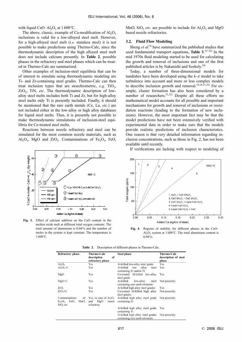
Themodynamic calculations of Ca-treatment of Al-killedsteel were made using Thermo-Calc.5) The IRSID Slagmodel was used for the slag phase.6,7) Figure 3 illustrateshow the CaO content in liquid CaO–Al2O3 varies at differ-ent amounts of added Ca and total oxygen contents at1 600°C.8) The calcium yield is assumed to be 100%. Thesolid lines, marked 1, 2 and 3, represent the composition ofthe molten oxide phase.
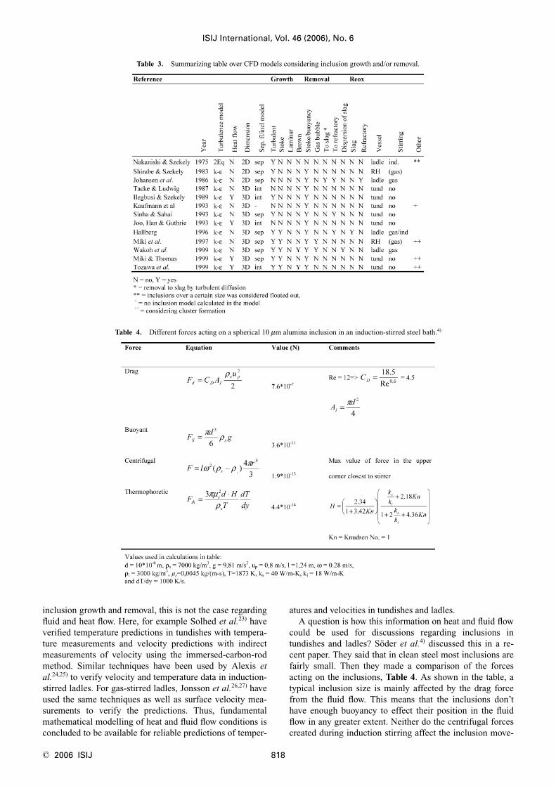
Figure 4 shows the area of stability of different phases of
calcium aluminates as functions of the total oxygen contentand the amount of calcium.8) The total Al content is 0.04and the calcium yield is assumed to be 100%. At 1 600°C,the stable phases are Al2O3, CaO·6Al2O3, CaO·2Al2O3,liquid CaO–Al2O3 and CaO.6,7) (If the temperature is low-ered to 1 500°C CaO·Al2O3 and 3CaO·Al2O3 can also beformed.) From the figure it can be seen that when the totaloxygen content was increased, to for example 100 ppm, thecalcium amount required to modify alumina inclusions toliquid CaO–Al2O3 was shifted towards higher values. It canalso be noted that the calculations in Figs. 3 and 4 did notpredict the existence of solid CaO·Al2O3 in equilibrium
ISIJ International, Vol. 46 (2006), No. 6
© 2006 ISIJ 816
Fig. 2. The number of inclusions at the different positions as a function of time (minutes) in the induction stirring experi-ment. A dashed vertical line shows the end of the aluminium addition. The oxygen activity is plotted and is readon the ordinate to the right in each plot. “Total oxygen” is the sum of DT, DM, DH and DP size classes.
with liquid CaO–Al2O3 at 1 600°C.The above, classic, example of Ca-modification of Al2O3
inclusions is valid for a low-alloyed steel melt. However,for a high-alloyed steel melt (i.e. stainless steel) it is notpossible to make predictions using Thermo-Calc, since thethermodynamic description of the high alloyed steel meltdoes not include calcium presently. In Table 2, possiblephases in the refractory and steel phases which can be treat-ed in Thermo-Calc are summarized.
Other examples of inclusion-steel equilibria that can beof interest to simulate using thermodynamic modeling areTi- and Zr-containing steel grades. Thermo-Calc can thentreat inclusion types that are stoechiometric, e.g. TiO2,ZrO2, TiN, etc. The thermodynamic description of low-alloy steel melts includes both Ti and Zr, but for high-alloysteel melts only Ti is presently included. Finally, it shouldbe mentioned that the rare earth metals (Ce, La, etc.) arenot included either in the low-alloy or high alloy databasesfor liquid steel melts. Thus, it is presently not possible tomake thermodynamic simulations of inclusion-steel equi-libria for Ce-treated steel melts.
Reactions between nozzle refractory and steel can besimulated for the most common nozzle materials, such asAl2O3, MgO and ZrO2. Contaminations of Fe2O3, FeO,
MnO, SiO2 etc. are possible to include for Al2O3 and MgObased nozzle refractories.
3.2. Fluid Flow Modeling
Sheng et al.9) have summarized the published studies thatused fundamental transport equations, Table 3.10–22) In themid 1970s fluid modeling started to be used for calculatingthe growth and removal of inclusions and one of the firstpublished articles is by Nakanishi and Szekely.10)
Today, a number of three-dimensional models fortundishes have been developed using the k–e model to taketurbulence into account and more or less complex modelsto describe inclusion growth and removal.14,16,21,22) For ex-ample, cluster formation has also been considered by anumber of researchers.21,22) Despite all these efforts nomathematical model accounts for all possible and importantmechanisms for growth and removal of inclusions or reoxi-dation reactions (leading to the formation of new inclu-sions). However, the most important fact may be that themodel predictions have not been extensively verified withexperimental data in order to make sure that the modelsprovide realistic predictions of inclusion characteristics.One reason is that very detailed information regarding in-clusion concentrations, such as those in Fig. 2, has not beenavailable until recently.
If verifications are lacking with respect to modeling of
ISIJ International, Vol. 46 (2006), No. 6
817 © 2006 ISIJ
Table 2. Description of different phases in Thermo-Calc.
Fig. 3. Effect of calcium addition on the CaO content in themolten oxide melt at different total oxygen contents. Thetotal amount of aluminium is 0.04% and the number ofmoles in the system is kept constant. The temperature is1 600°C.
Fig. 4. Regions of stability for different phases in the CaO–Al2O3 system at 1 600°C. The total aluminium content is0.04%.
inclusion growth and removal, this is not the case regardingfluid and heat flow. Here, for example Solhed et al.23) haveverified temperature predictions in tundishes with tempera-ture measurements and velocity predictions with indirectmeasurements of velocity using the immersed-carbon-rodmethod. Similar techniques have been used by Alexis etal.24,25) to verify velocity and temperature data in induction-stirred ladles. For gas-stirred ladles, Jonsson et al.26,27) haveused the same techniques as well as surface velocity mea-surements to verify the predictions. Thus, fundamentalmathematical modelling of heat and fluid flow conditions isconcluded to be available for reliable predictions of temper-
atures and velocities in tundishes and ladles.A question is how this information on heat and fluid flow
could be used for discussions regarding inclusions intundishes and ladles? Söder et al.4) discussed this in a re-cent paper. They said that in clean steel most inclusions arefairly small. Then they made a comparison of the forcesacting on the inclusions, Table 4. As shown in the table, atypical inclusion size is mainly affected by the drag forcefrom the fluid flow. This means that the inclusions don’thave enough buoyancy to effect their position in the fluidflow in any greater extent. Neither do the centrifugal forcescreated during induction stirring affect the inclusion move-
ISIJ International, Vol. 46 (2006), No. 6
© 2006 ISIJ 818
Table 3. Summarizing table over CFD models considering inclusion growth and/or removal.
Table 4. Different forces acting on a spherical 10 mm alumina inclusion in an induction-stirred steel bath.4)
ments. Instead, they follow the general flow and are mostlikely more influenced by the variations of the fluid flow inthe steel. As the fluid flow in the ladle is turbulent in vary-ing degree, eddies will throw inclusions between the bulkstream lines. This mixes the liquid steel and causes smoothconcentration gradients. Söder et al.4) also pointed out thatthe thermophoretic force is seen to be very small in thebulk, but could be important close to a cold wall. Thus, itmight be of importance when studying clogging of nozzles.
Fundamental mathematical modelling is concluded to beavailable to predict how inclusions are transported in atundish or a ladle, in particular small inclusions. Since onlythe size of the grain refiner and its density is of great im-portance, any types of grain refiners can be modelled. Morespecifically, since grain refiners are of sub-micron size, theywill for sure follow the fluid flow. Thus, fluid flow model-ling can be used to study the optimum position for grain re-fining addition so that, for example, the concentration ofgrain refiners is homogeneous in the outlet region.However, note that this is only true if the grain refiners donot significantly grow in size during the transport, sincethen they might be too large so to follow the main fluid flowpattern due to buoyancy.
3.3. Confocal Scanning Laser Microscopy
It was mentioned earlier that potential grain refiners needto be thermodynamically stable as well as be of a sub-mi-cron size. Thus, if these inclusions are added to a liquidsteel melt they should not react with the surroundings orform clusters in connection to colliding each other. Thelikelihood of forming clusters will be less the smaller theattraction forces between inclusions are.
The CSLM technique developed at Tohoku University byEmi and co-workers28) has shown to be a very valuable toolto study how inclusions behave on a molten steel surface.Here, it is possible to study how inclusions interact whenthey come closer. Sometimes their attraction forces are lowresulting in repelling of the inclusions. Other times the at-traction forces are higher resulting in them forming clus-ters.
It should be stressed that before studying potential grainrefiners using the CSLM technique it is necessary to makea mother metal containing the desirable inclusions, whichfor example has been described by Todoroki.29) The re-searchers in the Suito laboratory at Tohoku University havealso developed a new method for determination of the sizedistribution of sub-micron inclusions.30)
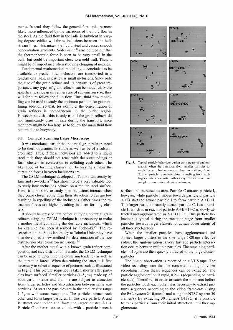
After the mother metal with a known grain refiner com-position and size distribution is made, the CSLM techniquecan be used to determine the clustering tendency as well asthe attraction forces. When determining the latter, it is firstnecessary to select a sequence of pictures such as illustratedin Fig. 5. This picture sequence is taken shortly after parti-cles have surfaced. Smaller particles (1–5 mm) made up ofboth cerium oxide and alumina are subject to attractionfrom larger particles and also attraction between same sizeparticles. At start the particles are in the smaller size range1–5 mm with some exceptions. The particles attract eachother and form larger particles. In this case particle A andB attract each other and form the larger cluster A�B.Particle C either rotate or collide with a particle beneath
surface and increases its area. Particle C attracts particle I,however, while particle I moves towards particle C particleA�B starts to attract particle I to form particle A�B�I.This larger particle instantly attracts particle C. Least parti-cle H which is in reach of particle A�B�I�C is slowly at-tracted and agglomerated in A�B�I�C. This particle be-haviour is typical during the transition stage from smallerparticles towards larger clusters for in-situ observations ofall three steel-grades.
When the smaller particles have agglomerated andformed larger clusters in the size range �20 mm effectiveradius, the agglomeration is very fast and particle interac-tion occurs between multiple particles. The remaining parti-cles �10 mm are then quickly attracted to the large cluster-particles.
The in-situ observation is recorded on a VHS tape. Thevideo recordings can then be converted to digital videorecordings. From these, sequences can be extracted. Theparticle agglomeration is rapid, 0.2–1 s (depending on parti-cle size). Therefore, in order to catch the moments beforethe particles touch each other, it is necessary to extract pic-tures sequences according to the video frame-rate (usingthe PAL system 24 frames/s and using the NTSC system 30frames/s). By extracting 30 frames/s (NTSC) it is possibleto track particles from their initial attraction until they ag-glomerate.
ISIJ International, Vol. 46 (2006), No. 6
819 © 2006 ISIJ
Fig. 5. Typical particle behaviour during early stages of agglom-eration, when the transition from smaller particles to-wards larger clusters occurs close to melting front.Smaller particles dominate close to melting front whilelarger clusters dominate further away. The inclusions arecomplex cerium oxide alumina inclusions.

With picture sequences showing particle agglomeration itis possible to evaluate the particles physical parametersframe by frame. Softwares such as WinROOF©31) can beutilized to calculate particle parameters such as perimeter,area, center of gravity, radius, etc. These parameters arenecessary to calculate when predicting the particle attrac-tion force and the attraction length between particles. Theattraction force between particles on a molten steel surfacecan be calculated experimentally by using physical parame-ters extracted from softwares such as WinROOF or theoret-ically by using mathematical models such as described byNakajima and Mizoguchi.32)
Figure 6 shows the variation of the attraction force be-tween two cerium oxide-alumina particles as a function ofthe distance between the particles. Here, the host particle ineach particle pair has approximately the same radius,�3 mm. The guest (r4) particle has a varying radius de-pending on particle pair. In particle pair B1 r4�3 mm, pairB2 r4�8–10 mm, pair B3 r4�19–25 mm. It can be seen thatthe inclusion pairs B1 and B2 have almost the same attrac-tion force although the size of the larger particle in B2 isthree times as large as in B1. The attraction length (start ofattraction between particle pair) is increasing with in-creased guest particle radius. In general, the attraction forceis seen not to be influenced as much by the size differenceas by the acting length between particles.
When selecting an appropriate grain refiner it is impor-tant to determine which has the smallest attraction force,but still has the other important properties necessary forgrain refining. Here it should be kept in mind that the capil-lary force between the inclusion and the steel is the forcethat acts on a liquid steel surface. Furthermore, the wetta-bility between the inclusions and the liquid steel is a keyissue to address to avoid agglomeration. Thus, it might beappropriate to first determine the wettability for some po-tential grain refiners. Thereafter, the attraction forces can bedetermined using the CSLM technique. Thereafter, the ten-dency for clogging should be studied using laboratory ex-periments.
Besides agglomeration between inclusions on a melt sur-face the CSLM technique also has the potential to be usedto study the following significant phenomena related tograin refining in-situ:• Solidification nucleation in the melt• Delta/gamma phase transformation• Pinning of gamma-grain growth• Formation of intra-granular ferrite
3.4. Laboratory Studies
Based on thermodynamic modeling and CSLM measure-ments potential grain refiners need to be tested for theirclogging tendency. Laboratory studies of this kind were firstdone by Duderstadt et al.33) and Farell and Hilty.34) In boththese cases deoxidised liquid steel was teemed into atundish and subsequently cast through a nozzle. In the latterstudy, they also continuously weighed the cast steel. Theadvantage of using this experimental approach is that a con-stant ferrostatic head in the tundish can be kept during partof the experiment. However, a major disadvantage is thatthe teeming of steel into the tundish cause reoxidation aswell as an uncontrolled formation of inclusions. Thus,Andersson and Wijk35) developed a similar technique fo-cused on how deoxidation technique as well as inclusionshave an influence on nozzle clogging. A sketch of the ex-perimental set-up is shown in Fig. 7. An induction furnace,with the lower part open, was positioned on a stand of 0.9m height. An alumina crucible with a bottom casting nozzlewas placed inside the furnace. The weight of the teemedsteel was continuously registered on a recorder during theexperiment. The temperature of the steel bath was mea-sured by a B-type thermocouple, protected by an aluminatube. An alumina stopper was placed in the nozzle to pre-
ISIJ International, Vol. 46 (2006), No. 6
© 2006 ISIJ 820
Fig. 6. Attraction force between two particles in a particle pairas a function of distance between the particles during par-ticle attraction. The host particle (r1) has a constant di-ameter (3 mm) in all particle pairs (B1, B2 and B3). Theguest particle (r4) has varying diameter depending onparticle pair: pair B1 has r4�3 mm, pair B2 has r4�
8–10 mm and pair B3 has r4�19–25 mm.
Fig. 7. Illustration of the nozzle blockage experimental set-up.

vent molten metal from penetrating into the nozzle beforethe teeming should start.
Figure 8 shows the two different nozzle geometries:angle-entry and radius-entry nozzles. The angle-entry noz-zles were made of alumina-magnesite or zirconium-silicateand the radius-entry nozzles of zirconium-silicate.
The angle-entry nozzles could be heated by placing agraphite ring around the lower part of the nozzle and a sep-arate high frequency loop system as shown in Fig. 9. In theexperiments with nozzle heating, a B-type thermocouplemeasured the refractory temperature at the point where theconvergent section was transferred to the cylindrical.
10 kg of steel with the following composition was meltedin the alumina crucible at a constant flow of argon gasabove the metal: 0.26% C, 0.19% Si, 1.05% Mn, 0.48%Cr, 0.062% Ni, 0.017% P and 0.012% S. The liquidus tem-perature of the alloy was estimated to be 1 508°C.5) Aftermelting, the steel temperature was kept constant at 1 545°Cfollowed by an addition of 40 g of magnetite to increase theoxygen content. The steel bath was homogenised during3 min before deoxidation, which was done by plunging analuminium metal foil into the melt. The added amounts ofaluminium varied from 0 to 0.3% (by weight). After 5 sfrom deoxidation the electric power was turned off. Theteeming started 25 s after the moment of deoxidation andthe molten steel was generally allowed to flow until the noz-zle was completely blocked. The temperature drop in thesteel melt was usually 20–30°C during the teeming, whichlasted for 30–80 s.
During teeming, steel samples were taken from the metalbulk by using a silica tube. The steel samples were analysedfor dissolved aluminium by atomic absorption and totaloxygen by fusing method and infrared exposure. After theexperiments, the nozzles, with the solid steel inside, wereprepared for examination in an optical microscope. Somesamples were further analysed in Scanning Electron Micro-
scope (SEM). The refractory surfaces of the samples andalso the metal with the oxide build-up were examined.
3.4.1. Effect of Aluminium on Teeming Rate
The investigation by SEM revealed that the majority ofthe oxides in the build-up consisted of alumina clusters(Al2O3). The oxide deposition pattern (Figs. 10 and 11)showed that the build-up was concentrated in the entrancesand the upper part of the cylindrical sections of both theangle-entry and the radius-entry nozzle geometries.
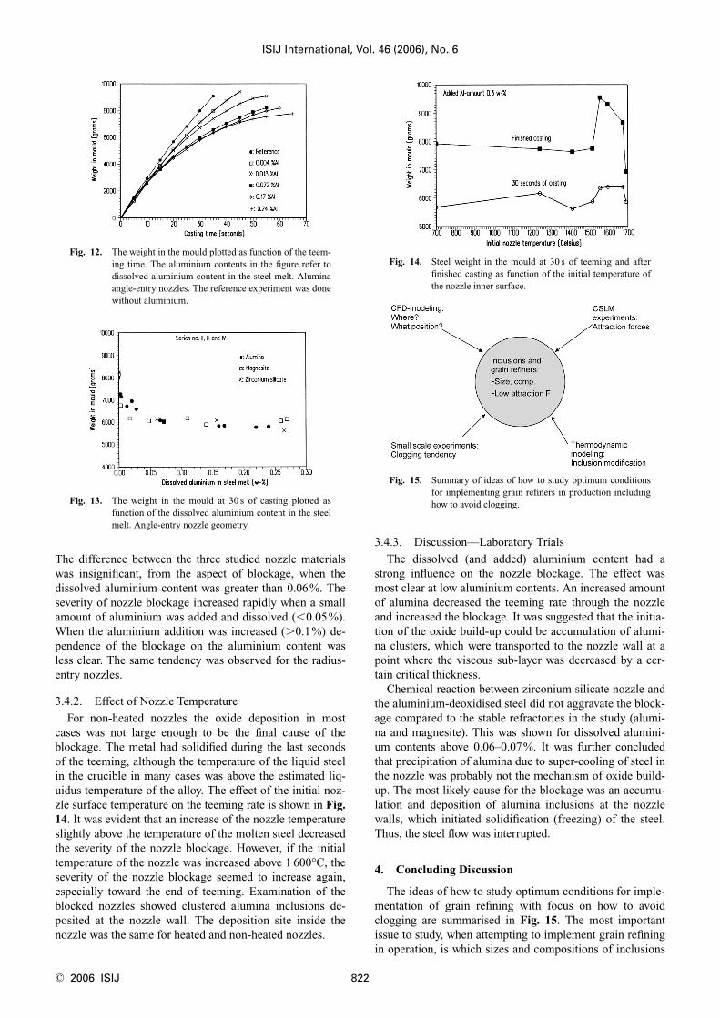
The experimental results showed a strong relationshipbetween the dissolved content of aluminium in the moltensteel and the teemed weight in the mould. This is illustratedin Fig. 12, where the weight of teemed steel is plotted as afunction of the teeming time for alumina angle-entry noz-zles. Increased aluminium content in the steel melt de-creased the teeming rate. The same characteristic behaviourwas observed for the other nozzle materials and also for theradius-entry nozzle geometry.
In Fig. 13 the results from the angle-entry nozzles (alu-mina, magnesite and zirconium silicate) are compared byplotting the weight of steel in mould at 30 s of teemingagainst the dissolved aluminium content in the steel melt.
ISIJ International, Vol. 46 (2006), No. 6
821 © 2006 ISIJ
Fig. 8. Geometries of nozzles: a) angle-entry nozzle and b) ra-dius-entry nozzle.
Fig. 9. Schematic illustration of the nozzle heating arrangement.
Fig. 10. Deep-etched sample of steel and cluster in an angle-entry nozzle.
Fig. 11. Oxide build-up in the radius-entry nozzle. The exit noz-zle diameter is 6.5 mm.
The difference between the three studied nozzle materialswas insignificant, from the aspect of blockage, when thedissolved aluminium content was greater than 0.06%. Theseverity of nozzle blockage increased rapidly when a smallamount of aluminium was added and dissolved (�0.05%).When the aluminium addition was increased (�0.1%) de-pendence of the blockage on the aluminium content wasless clear. The same tendency was observed for the radius-entry nozzles.
3.4.2. Effect of Nozzle Temperature
For non-heated nozzles the oxide deposition in mostcases was not large enough to be the final cause of theblockage. The metal had solidified during the last secondsof the teeming, although the temperature of the liquid steelin the crucible in many cases was above the estimated liq-uidus temperature of the alloy. The effect of the initial noz-zle surface temperature on the teeming rate is shown in Fig.14. It was evident that an increase of the nozzle temperatureslightly above the temperature of the molten steel decreasedthe severity of the nozzle blockage. However, if the initialtemperature of the nozzle was increased above 1 600°C, theseverity of the nozzle blockage seemed to increase again,especially toward the end of teeming. Examination of theblocked nozzles showed clustered alumina inclusions de-posited at the nozzle wall. The deposition site inside thenozzle was the same for heated and non-heated nozzles.
3.4.3. Discussion—Laboratory Trials
The dissolved (and added) aluminium content had astrong influence on the nozzle blockage. The effect wasmost clear at low aluminium contents. An increased amountof alumina decreased the teeming rate through the nozzleand increased the blockage. It was suggested that the initia-tion of the oxide build-up could be accumulation of alumi-na clusters, which were transported to the nozzle wall at apoint where the viscous sub-layer was decreased by a cer-tain critical thickness.
Chemical reaction between zirconium silicate nozzle andthe aluminium-deoxidised steel did not aggravate the block-age compared to the stable refractories in the study (alumi-na and magnesite). This was shown for dissolved alumini-um contents above 0.06–0.07%. It was further concludedthat precipitation of alumina due to super-cooling of steel inthe nozzle was probably not the mechanism of oxide build-up. The most likely cause for the blockage was an accumu-lation and deposition of alumina inclusions at the nozzlewalls, which initiated solidification (freezing) of the steel.Thus, the steel flow was interrupted.
4. Concluding Discussion
The ideas of how to study optimum conditions for imple-mentation of grain refining with focus on how to avoidclogging are summarised in Fig. 15. The most importantissue to study, when attempting to implement grain refiningin operation, is which sizes and compositions of inclusions
ISIJ International, Vol. 46 (2006), No. 6
© 2006 ISIJ 822
Fig. 12. The weight in the mould plotted as function of the teem-ing time. The aluminium contents in the figure refer todissolved aluminium content in the steel melt. Aluminaangle-entry nozzles. The reference experiment was donewithout aluminium.
Fig. 13. The weight in the mould at 30 s of casting plotted asfunction of the dissolved aluminium content in the steelmelt. Angle-entry nozzle geometry.
Fig. 14. Steel weight in the mould at 30 s of teeming and afterfinished casting as function of the initial temperature ofthe nozzle inner surface.
Fig. 15. Summary of ideas of how to study optimum conditionsfor implementing grain refiners in production includinghow to avoid clogging.
have the largest positive influence on grain refinement. Thisinformation is provided by physical metallurgists. In orderto ensure that these grain refiners are available at the onsetof solidification a number of theoretical as well as practicalmeasures have to be considered. Thermodynamic modelingcan, to some extent, be used to predict what additions tomake to create potential grain refiners. However, here oneshould be aware of that much thermodynamic data is notavailable for steel alloys of interest, as was pointed out inthe discussion of Table 2. This is especially true for high-alloy steel grades, where further theoretical and experimen-tal studies are necessary to be carried out in the future.
Mathematical modeling can be used to study where toadd potential grain refiners. Here, it is seen to be advanta-geous to add grain refiners in the tundish. The reason is thatenough time is given to a complete mixing of the grain re-finer into the steel before the steel enters the mold. Besidesbeing useful as nucleation sites during solidification thecomposition of potential grain refiners must also be suchthat they have a low clogging tendency while being trans-ported in the steel. In order to minimize nozzle clogging, anincreased knowledge regarding the phenomena causingclogging is needed.
By using the CSLM technique it is possible to study in-teractions between different inclusion types in-situ. In addi-tion, it is possible to measure attraction forces between dif-ferent inclusion types. Here, the inclusion types can be de-termined using SEM. Based on this information thermody-namic calculations can be made to calculate the conditionsfor how inclusions can be modified in order to obtain prop-erties of lower attraction forces. Finally, laboratory experi-ments should be carried out to study nozzle clogging. Inthis way, many different sets of experiments can be carriedout in a cheap manner in a laboratory, before costly planttrials are initiated to study the grain refining efficiency.
Acknowledgements
The authors wish to thank the Swedish Steel Producer’sAssociation for financial support to this study.
REFERENCES
1) Ö. Grong, P. Jönsson and O.-S. Klevan: Proc. Infacon Nine, TheFerroalloys Association, Quebec, (2001), 562.
2) K. Nakajima, H. Hasegawa, S. Khumkoa and S. Mizoguchi: Metall.Mater. Trans. B, 34B (2003), 539.
3) L. Kolbeinssen, CAMP-ISIJ, 18 (2005), 853.4) M. Söder, P. Jönsson, L. Jonsson and M. Nzotta: Steel Res. Int., 7
(2005), 481.5) B. Sundman, B. Jansson and J.-O. Andersson: Calphad, 9 (1985),
153.6) H. Gaye and J. Welfringer: Proc. 2nd Int. Symp. on Molten Slags and
Fluxes, Met. Soc. AIME, Warrendale, PA, (1984), 357.7) H. Gaye, P. V. Riboud and J. Welfringer: 3rd Conf. on Molten Slags
and Fluxes, The Inst. of Metals, London, (1988), 259.8) M. Andersson: PhD Thesis, Div. of Metallurgy, KTH, Sweden,
(2000), ISBN: 91-7170621-6.9) D.-Y. Sheng, M. Söder, P. Jönsson and L. Jonsson: Scand. J. Met., 31
(2002), 134.10) K. Nakanishi and J. Szekely: Trans. Iron Steel Inst. Jpn., 15 (1975),
522.11) K. Shirabe and J. Szekely: Trans. Iron Steel Inst. Jpn., 23 (1983),
465.12) S. T. Johansen, F. Boysan and T. A. Engh: Proc. 4th Japan-Nordic
Countries Joint Symp. on Science and Technology of ProcessMetallurgy, ISIJ, Tokyo, (1986), 182.
13) K.-H. Tacke and J. C. Ludwig: Steel Res., 58 (1987), 262.14) O. J. Ilegbusi and J. Szekely: ISIJ Int., 29 (1989), 1031.15) B. Kaufmann, A. Niedermeyr, H. Sattler and A. Preuer: Steel Res.,
64 (1993), 203.16) A. K. Sinha and Y. Sahai: ISIJ Int., 33 (1993), 556.17) S. Joo, J. W. Han and R. I. L. Guthrie: Metall. Trans. B, 24B (1993),
767.18) M. Hallberg: Tech. lic. Thesis, KTH, Sweden, (1996), ISBN: 91-
71706941.19) Y. Miki, Y. Shimada, B. G. Thomas and A. Denisov: Trans. ISS, Iron
Steelmaker, 28 (1997), 31.20) M. Wakoh, K. Fuchigami, K. Endoh, N. Imamura, A. Kiyose and I.
Sawada: Scanmet I, MEFOS, Luleå, Sweden, (1999), 267.21) Y. Miki and B. G. Thomas: Metall. Trans. B, 30B (1999), 639.22) H. Tozawa, Y. Kato, K. Sorimachi and T. Nakanishi: ISIJ Int., 39
(1999), 426.23) H. Solhed, L. Jonsson and P. Jönsson: Metall. Mater. Trans. B, 33B
(2002), 173.24) J. Alexis and P. G. Jönsson: Scand. J. Met., 26 (1997), 48.25) J. Alexis: PhD Thesis, Div. of Metallurgy, KTH, Stockholm, Sweden,
(2000), ISBN 91-7170551-126) P. G. Jönsson and L. Jonsson: Scand. J. Met., 24 (1995), 194.27) C.-E. Grip, K. O. Jonsson, S. Eriksson, L. Jonsson, P. Jönsson and Y.
Pan: Scand. J. Metall., 29 (2000), 30.28) H. Chikama, C. Yu, H. Shibata, M. Suzuki and T. Emi: Bull. Inst.
Adv. Mater. Process., Tohoku Univ., 51 (1995), No. 1, 2, 35. 29) H. Todoroki: PhD Thesis, Suito laboratory, Tohoku University,
Sendai, (2003).30) H. Suito, H. Ohta and S. Morioka: CAMP-ISIJ, 18 (2005), 857.31) MITANI Corporation: �http://www.image.mitani-corp.co.jp�.32) K. Nakajima and S. Mizoguchi: Metall. Mater. Trans. B, 32B (2001),
629. 33) G. C. Duderstadt, R. K. Iyengar and J. M. Matesa: J. Met., 20 (1968),
89.34) J. W. Farrell and D. C. Hilty: Electric Furnace Proc., 29, AIME, New
York, (1971), 31.35) M. Andersson and O. Wijk: Scaninject VI Proc., Part II, MEFOS,
Luleå, (1992), 175.
ISIJ International, Vol. 46 (2006), No. 6
823 © 2006 ISIJ