Embed Size (px)
Citation preview

Solving Hard Instances of Floorplacement
Aaron Ng, Igor L. MarkovDepartment of EECS
The University of Michigan1301 Beal Ave
Ann Arbor, MI 48109
{aaronnn, imarkov}@umich.edu
Rajat AggarwalXilinx, Inc.
2100 Logic DrSan Jose, CA 95124
Venky RamachandranCalypto Design Systems, Inc.
2933 Bunker Hill LaneSanta Clara, CA 25054
ABSTRACTPhysical Design of modern systems on chip is extremely challeng-ing. Such digital integrated circuits often contain tens of millionsof logic gates, intellectual property blocks, embedded memoriesand custom RTL blocks. At current and future technology nodes,their power and performance are impacted, more than ever, by theplacement of their modules. However, our experiments show thattraditional techniques for placement and floorplanning, and exist-ing academic tools cannot reliably solve the placement task.
To study this problem, we identify particularly difficult industrialinstances and reproduce the failures of existing tools by modifyingpublic-domain netlists. Furthermore, we propose algorithms thatfacilitate floorplacement of these difficult instances. Empirically,our techniques consistently produced legal placements, and on in-stances where comparison is possible, reduced wirelength by 3.5%over Capo 9.4 and 14.5% over PATOMA 1.0 — the pre-existingtools that most frequently produced legal placements in our exper-iments.
Categories and Subject Descriptors: B.7.2 [Integrated Cir-cuits]: Design Aids — placement and routing; J.6 [Computer-Aided Engineering]: Computer-Aided Design.General Terms: Algorithms, experimentationKeywords: Circuit layout, placement, floorplanning, floorplace-ment, benchmarks, RTL
1. INTRODUCTIONAs demonstrated by the ISPD 2005 placement contest, auto-
mated layout of modern systems-on-chip (SoCs) is very differentfrom traditional sea-of-gates layout, both in scale and sophistica-tion. Such integrated circuits (ICs) may contain tens of millions oflogic gates, hundreds of complex configurable intellectual property(IP) blocks, embedded memories that come in different sizes andaspect ratios, as well as custom RTL blocks. Placement plays a keyrole not only in the final implementation stage, but also in the earlystages of the design flow by enabling more accurate interconnectand performance analysis. To be useful in estimation, placementtechniques must support very high capacity, complete quickly andbe robust across a variety of designs.
Permission to make digital or hard copies of all or part of this work forpersonal or classroom use is granted without fee provided that copies arenot made or distributed for profit or commercial advantage and that copiesbear this notice and the full citation on the first page. To copy otherwise, torepublish, to post on servers or to redistribute to lists, requires prior specificpermission and/or a fee.ISPD’06, April 9–12, 2006, San Jose, California, USA.Copyright 2006 ACM 1-59593-299-2/06/0004 ...$5.00.
To improve capacity and runtime, we observe that at the register-transfer level and above, the design intent is expressed in termsof word-level arithmetic and logical operators within separate par-allel hardware threads or “always” blocks in Verilog. It is nei-ther necessary nor even desirable to decompose these operatorsinto bit-level (gate-level) netlists in order to estimate performance,which requires knowing locations. Such a transformation often in-creases the number of modules by 20-50x, especially for designswith wide datapaths, and complicates interconnect analysis. How-ever, since word-level operators are known in advance, one can pre-characterize their area, timing and power, essentially building anRTL library. During placement, such library components can beviewed as soft blocks of a particular size and shape, subject to cer-tain aspect ratio constraints (with hard blocks being a special case).
The task of finding non-overlapping locations of modules ofvarying sizes while optimizing for certain objective(s) is usuallycalled floorplanning. However, traditional floorplanning does notscale beyond a few hundred placeable modules. On the other hand,standard-cell placement can deal with millions of instances, exceptthat those instances are assumed to have identical heights and sim-ilar lengths, which helps fitting them in equally-spaced rows andsites. These constraints prevent difficult block-packing, while facil-itating fast and high-quality detailed placement algorithms. How-ever, their use for RTL entities remains unexplored.
A recent unification of placement and floorplanning termedfloorplacement [24] seeks to bridge the gap between floorplanningand placement by combining their best features. Floorplacementappears promising for SoC layout because of its high capacity andthe ability to pack blocks. However, as our experiments demon-strate, existing tools for floorplacement are fragile — on many in-stances we tried they fail, or produce remarkably poor placements.This observation sets the stage for our work, in which we make thefollowing contributions:
• We identify hard floorplacement instances derived from in-dustry designs and modify public-domain netlists to behavesimilarly. We explain why existing algorithms for mixed-sizeplacement and floorplanning fail on hard instances.
• We propose four synergistic techniques for floorplacementthat in particular succeed on hard instances: (i) selectivefloorplanning with macro clustering, (ii) improved obstacleevasion for B*-trees, (iii) ad hoc look-ahead in top-downfloorplacement, and (iv) whitespace allocation by density.Obstacle evasion is especially important for top-down floor-placement, even for designs that initially have no obstacles.
• We demonstrate empirical improvements compared to Capo9.4 and PATOMA 1.0. Our techniques lead to 68% and 36%increase in success rates in floorplacement, and shorter wire-length by 3.5% and 14.5%, respectively.
The rest of this paper is organized as follows. We review currentstate-of-the-art in mixed-size placement and floorplanning in Sec-tion 2, and describe the nature of difficult instances in Section 3.In Section 4 we evaluate existing software tools, show their limi-tations and identify the weaknesses of core algorithms. Our algo-rithmic improvements are presented in Section 5 and empiricallyevaluated in Section 6. Conclusions are summarized in Section 7.
2. PREVIOUS WORKIn this section, we outline the state-of-the-art in mixed-size
placement and floorplanning. First, we discuss floorplanning andintroduce basic computational techniques for block packing. Thenwe show a natural progression to hierarchical floorplanning, mixed-size placement and floorplacement.
Common approaches to floorplanning. Modern VLSI floor-planning is predominantly used with fixed outlines [4, 16]. Thefixed-outline floorplanning problem seeks non-overlapping loca-tions of modules (blocks) within a fixed outline, subject to opti-mizing for certain objective(s), such as wirelength, power or per-formance. The most popular algorithmic framework in floorplan-ning is Simulated Annealing and is implemented using a certainfloorplan representation that captures relative locations of modulesand is easy to perturb, but can also generate non-overlapping mod-ule locations. Simulated annealing is attractive because it allowsto optimize a wide variety of objective functions and makes cus-tomization very easy. It can deal with hard blocks with any aspectratios and also soft blocks. It also allows to handle fixed modules,as discussed in Section 5. Sequence-Pair [22] and B*-tree [8] aretwo popular floorplan representations.
The Sequence-Pair representation consists of two ordered lists,which capture geometric relations between pairs of blocks by therelative ordering of blocks. However, in our work we use themore complicated B*-tree representation which captures a com-pacted packing by a binary tree, in which each node corresponds toa block. The root of the tree is in the bottom-left corner of the out-line, and the packing is compacted in that direction. The root noderepresents the bottom-left block. A left child is the lowest rightneighbor of its parent and a right child is the lowest block aboveits parent that shares the same x-coordinate as its parent [7]. Givena B*-tree, block locations can be found by a depth-first traversalof the B*-tree. After a block A is placed at (xA,yA), its left childL is considered and set xL = xA + wA, where wA is the width ofA. Then yL is the smallest non-negative value such that L avoidsoverlaps with previously placed blocks. After returning from re-cursion at L, the right child of A, R is placed at xR = xL, and yRis the smallest value possible such that R does not overlap withplaced blocks. The contour data structure allows one to evaluateB*-tree packings in O(n) time. The two floorplan representationsencode large solution spaces: O(n!22n−2/n1.5) for B*-tree and n!2
for Sequence-Pair. According to [7], B*-tree packs somewhat bet-ter than Sequence-Pair. Additionally, we found that it better sup-ports the handling of obstacles.
Parquet [1] is a floorplanning framework based on simulated an-nealing and uses both Sequence-Pair and B*-tree representations.Parquet produces high-quality solutions, but due to the runtime ofthe simulated annealing framework, it cannot be practically appliedon large designs without clustering [24].
Hierarchical floorplanning, mixed-size placement and floor-placement. PATOMA 1.0 [13] pioneered a top-down floorplan-ning framework that utilizes fast block-packing algorithms (ROBor ZDS [12]) and hypergraph partitioning with hMetis [20]. Thisapproach is fast and scalable, and provides good solutions for manyinput configurations. Fast block-packing is used in PATOMA to
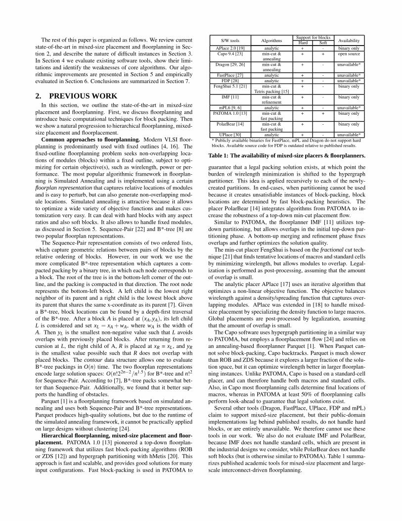
Support for blocksS/W tools Algorithms Hard Soft AvailabilityAPlace 2.0 [19] analytic + - binary onlyCapo 9.4 [23] min-cut & + + open source
annealingDragon [29, 26] min-cut & + - unavailable*
annealingFastPlace [27] analytic + - unavailable*
FDP [28] analytic + - unavailable*FengShui 5.1 [21] min-cut & + - binary only
Tetris packing [15]IMF [11] min-cut & + - binary only
refinementmPL6 [9, 6] analytic + - unavailable*
PATOMA 1.0 [13] min-cut & + + binary onlyfast packing
PolarBear [14] min-cut & + - binary onlyfast packing
UPlace [30] analytic + - unavailable** Publicly available binaries for FastPlace, mPL and Dragon do not support hardblocks. Available source code for FDP is outdated relative to published results.
Table 1: The availability of mixed-size placers & floorplanners.
guarantee that a legal packing solution exists, at which point theburden of wirelength minimization is shifted to the hypergraphpartitioner. This idea is applied recursively to each of the newly-created partitions. In end-cases, when partitioning cannot be usedbecause it creates unsatisfiable instances of block-packing, blocklocations are determined by fast block-packing heuristics. Theplacer PolarBear [14] integrates algorithms from PATOMA to in-crease the robustness of a top-down min-cut placement flow.
Similar to PATOMA, the floorplanner IMF [11] utilizes top-down partitioning, but allows overlaps in the initial top-down par-titioning phase. A bottom-up merging and refinement phase fixesoverlaps and further optimizes the solution quality.
The min-cut placer FengShui is based on the fractional cut tech-nique [21] that finds tentative locations of macros and standard cellsby minimizing wirelength, but allows modules to overlap. Legal-ization is performed as post-processing, assuming that the amountof overlap is small.
The analytic placer APlace [17] uses an iterative algorithm thatoptimizes a non-linear objective function. The objective balanceswirelength against a density/spreading function that captures over-lapping modules. APlace was extended in [18] to handle mixed-size placement by specializing the density function to large macros.Global placements are post-processed by legalization, assumingthat the amount of overlap is small.
The Capo software uses hypergraph partitioning in a similar wayto PATOMA, but employs a floorplacement flow [24] and relies onan annealing-based floorplanner Parquet [1]. When Parquet can-not solve block-packing, Capo backtracks. Parquet is much slowerthan ROB and ZDS because it explores a larger fraction of the solu-tion space, but it can optimize wirelength better in larger floorplan-ning instances. Unlike PATOMA, Capo is based on a standard-cellplacer, and can therefore handle both macros and standard cells.Also, in Capo most floorplanning calls determine final locations ofmacros, whereas in PATOMA at least 50% of floorplanning callsperform look-ahead to guarantee that legal solutions exist.
Several other tools (Dragon, FastPlace, UPlace, FDP and mPL)claim to support mixed-size placement, but their public-domainimplementations lag behind published results, do not handle hardblocks, or are entirely unavailable. We therefore cannot use thesetools in our work. We also do not evaluate IMF and PolarBear,because IMF does not handle standard cells, which are present inthe industrial designs we consider, while PolarBear does not handlesoft blocks (but is otherwise similar to PATOMA). Table 1 summa-rizes published academic tools for mixed-size placement and large-scale interconnect-driven floorplanning.

3. DIFFICULT INSTANCESSince block packing is NP-hard, a key challenge for heuristics
is to moderate their effort (runtime) while ensuring good solutionquality on a variety of inputs. To this end, we identified two sets ofnetlists that appear particularly difficult for all tools we evaluated.
Proprietary instances. The designs, provided by Calypto De-sign Systems, Inc., include customer chips (e.g., CPUs and videoICs) and internally-generated regression tests [32]. As shown inTable 2, these designs range in size from 81 to 8827 RTL mod-ules, have 20% whitespace, and have no fixed modules except forperipheral I/O pads. Aside from the standard cells present in mostdesigns, all blocks are soft. The main objective of our experimentsis to perform RTL placement using as many existing alternativetools as possible. To this end we have access to APlace 2.0, Capo9.4, FengShui 5.1 and PATOMA 1.0. Of these four tools, APlace2.0 and FengShui 5.1 do not support soft blocks, so the solutionspace is simplified for these placers by changing all soft blocksto hard blocks with an aspect ratio of 1.0 (the easiest to pack).However, even when Capo and PATOMA are run on hard-blockvariants of these designs, their runtimes and Half-Perimeter Wire-Length (HPWL) are only slightly worse, while the results are stillbetter than those of APlace and FengShui, with all other trends re-produced. The proprietary designs consist mostly of macros, andthe macros may vary greatly in size. As we show next, these de-signs upset existing academic tools for mixed-size placement andfloorplanning.
Proprietary Movable modules Arealargest Arealargest/designs Cells Macros Nets (%) Areasmallest
cal040 1 4605 4607 0.1 650cal098 3200 1212 4673 0.1 529cal336 17 105 147 2.2 11556cal353 217 459 908 7.0 11556cal523 934 1936 4350 0.3 3080cal542 7 74 92 20.1 11556cal566 93 1553 5502 1.2 11556cal583 773 1530 3390 0.4 2916cal588 293 495 1111 0.6 900cal643 139 316 598 6.5 6162
calDCT 0 8827 11463 50.0 185330
Table 2: Characteristics of the proprietary designs.
Movable modules Arealargest Arealargest/Benchmarks Cells Macros Nets (%) Areasmallest
ibm-HB+01 0 911 5829 6.4 8416ibm-HB+02 0 1471 8508 11.3 3004.3ibm-HB+03 0 1289 10279 10.8 33088ibm-HB+04 0 1584 12456 9.2 13296.5ibm-HB+06 0 749 9963 13.6 18173.8ibm-HB+07 0 1120 15047 4.8 399.5ibm-HB+08 0 1269 16075 12.1 50880ibm-HB+09 0 1113 18913 5.4 29707ibm-HB+10 0 1595 27508 4.8 71299ibm-HB+11 0 1497 27477 4.5 9902.3ibm-HB+12 0 1233 26320 6.4 74256ibm-HB+13 0 954 27011 4.2 33088ibm-HB+14 0 1635 43062 2.0 17860ibm-HB+15 0 1412 52779 11.0 62781.3ibm-HB+16 0 1091 47821 1.9 31093ibm-HB+17 0 1442 56517 0.9 12441ibm-HB+18 0 943 42200 1.0 3384
Table 3: Characteristics of the IBM-HB+ benchmarks.
Our experiments were conducted on a 2.4 GHz Athlon worksta-tion with 3GB RAM. As Capo uses a randomized algorithm, itsresults are averaged over 3 independent runs. Empirical results inTable 4 demonstrate that many existing tools experience difficul-ties even with smaller designs, indicating that scalability is not theonly problem here. Capo places all designs (some with overlaps),
but times out for the largest design calDCT with 8827 macros, sug-gesting that scalability is a serious issue nevertheless. The designcal040 appears challenging for PATOMA and APlace even thoughit has a small range of macro sizes, compared to other designs.
Public-domain instances. We reproduce the difficulties ob-served on hard floorplacement instances by modifying seventeenof the IBM-HB benchmarks released in [13], for further evaluationof difficult mixed-size placement1. The IBM-HB [13, 31] bench-marks were generated from the IBM/ISPD‘98 suite [3] and containboth hard and soft blocks in a fixed die with 20% whitespace. Thesoft blocks are clusters of standard cells while the hard blocks rep-resent original macros from the IBM/ISPD98 benchmarks. Thebenchmarks range from 500 to 2000 blocks in size. Our modifica-tion is as follows: the largest hard macro is inflated by 100%, whilethe areas of the remaining soft macros are reduced to preserve thetotal cell area. We call this new benchmark family IBM-HB+ [32].A more detailed future study can involve varying the dimensionsof more than one macro at a time, and even more difficult floor-placement problems can be constructed. For now, inflating onlythe largest macro and shrinking the rest is sufficient to reveal thelimitations of existing tools and provides enough food for thought.
4. IDENTIFYING WEAKNESSESIN FLOORPLACEMENT ALGORITHMS
By studying the data and plots collected, as well as logs producedby various tools, we identify shortcomings of published algorithms.
0
1000
2000
3000
4000
5000
6000
7000
8000
0 1000 2000 3000 4000 5000 6000 7000 8000 0
100
200
300
400
500
600
700
800
900
1000
0 100 200 300 400 500 600 700 800 900 1000
Figure 4: The IBM-HB+10 benchmark and the cal040 designare pathological examples for PATOMA 1.0, which producesplacements with HPWL that are 1.4x and 9.7x larger (resp.),than the best seen in legal solutions. These examples maybe highlighting shortcomings of fast block-packing algorithms,even when the variation of block sizes is relatively small.
PATOMA utilizes partitioning-based algorithms [13] that al-low it to solve floorplacement instances very quickly. When aset of floorplanning instances falls within the operating range ofPATOMA, resulting solutions are slightly better than Capo’s andare found several times faster. However, PATOMA seems to traderobustness for runtime and in some cases generates solutions withremarkably long wires — for example, Figure 4 shows PATOMAsolutions for the IBM-HB+10 benchmark and the cal040 design,which have 1.4x and 9.7x worse HPWL, respectively, compared tothe best seen solutions. This suggests that PATOMA’s algorithmsdo not adequately search the solution space, making PATOMA’sperformance unpredictable and inconsistent across the benchmarks.
Upon further analysis, the severe degradation in solution qualitycan be attributed to PATOMA’s “guarantors” — fast block-packingheuristics that guarantee legal solutions, but do not guarantee good
1We exclude IBM-HB05 because it does not contain hard macros.

0
100
200
300
400
500
600
700
800
900
1000
0 100 200 300 400 500 600 700 800 900 1000 0
100
200
300
400
500
600
700
800
0 100 200 300 400 500 600 700 800 0
100
200
300
400
500
600
700
800
900
0 100 200 300 400 500 600 700 800 900 0
50
100
150
200
250
300
350
400
450
500
0 50 100 150 200 250 300 350 400 450 500 0
200
400
600
800
1000
1200
0 200 400 600 800 1000 1200
CAL040 CAL098 CAL336 CAL353 CAL523
0
50
100
150
200
250
300
0 50 100 150 200 250 300 0
200
400
600
800
1000
1200
0 200 400 600 800 1000 1200 0
100
200
300
400
500
600
700
800
900
1000
0 100 200 300 400 500 600 700 800 900 1000 0
50
100
150
200
250
300
350
400
450
0 50 100 150 200 250 300 350 400 450 0
50
100
150
200
250
300
350
0 50 100 150 200 250 300 350
CAL542 CAL566 CAL583 CAL588 CAL643
Figure 1: Proprietary designs used in our work. Macros are shown in blue and standard cells in green.
0
500
1000
1500
2000
2500
3000
3500
4000
4500
0 500 1000 1500 2000 2500 3000 3500 4000 4500 0
1000
2000
3000
4000
5000
6000
7000
8000
0 1000 2000 3000 4000 5000 6000 7000 8000 0
1000
2000
3000
4000
5000
6000
7000
0 1000 2000 3000 4000 5000 6000 7000
IBM-HB+08 IBM-HB+10 IBM-HB+12
0
1000
2000
3000
4000
5000
6000
7000
0 1000 2000 3000 4000 5000 6000 7000 0
1000
2000
3000
4000
5000
6000
7000
8000
9000
0 1000 2000 3000 4000 5000 6000 7000 8000 9000 0
1000
2000
3000
4000
5000
6000
7000
0 1000 2000 3000 4000 5000 6000 7000
IBM-HB+14 IBM-HB+16 IBM-HB+18
Figure 2: Six of the seventeen IBM-HB+ benchmarks.
0
100
200
300
400
500
600
700
0 100 200 300 400 500 600 700
Figure 3: The 8827-macro design calDCT.
solutions. Indeed, when PATOMA fails to find a legal partition-ing solution, it resorts to the “guaranteed” floorplanning solutionproduced during look-ahead without sufficient regard to wirelengthminimization. PATOMA’s results suggest that hard instances ex-pose the gap between PATOMA’s predictions and its ability to im-plement them. Another possibility is that PATOMA’s fast guar-antors jump the gun and report failures when good packings exist(but take time to find). If either of these effects happens early in thePATOMA flow, PATOMA will produce an essentially random legalplacement, as it does on the cal040 design.
In contrast to PATOMA, Capo uses a much slower simulated-annealing floorplanner (Parquet) in bins (partitions) created dur-ing top-down min-cut placement. Parquet can handle up to 50-100blocks well [7], but then becomes inefficient for larger instances.A built-in clusterer, also requested by Capo, extends Parquet’s op-erating range but impacts solution quality. Capo’s floorplacementflow decides to floorplan a bin when a block is too large to fit ineither child-bin [24]. Given that large blocks are common in mod-ern designs (e.g., an L2 cache can take 50% of a microprocessor’sarea), Capo may decide to perform annealing near the top level, onalmost all the blocks in the design. When applied to thousands ofblocks, Parquet spends an inordinate amount of time and typically
0
1000
2000
3000
4000
5000
6000
7000
8000
0 1000 2000 3000 4000 5000 6000 7000 8000 0
100
200
300
400
500
600
700
800
900
0 100 200 300 400 500 600 700 800 900
Figure 5: The IBM-HB+10 benchmark and cal336 designplaced by Capo 9.4. These plots of illegal placements showthat partitioning may produce bins that are difficult (or impos-sible) to floorplan, since the partitioner may mis-approximatethe area required by a packing of the blocks. Overlaps betweenmodules are marked with red crosses.
does not find a reasonable solution. According to logs, Capo 9.4goes through this scenario on the proprietary design calDCT thatincludes a very large block, as shown in Figure 3.

PATOMA 1.0 Capo 9.4 -faster APlace 2.0 FengShui 5.1 SCAMPI (our work)cal HPWL ovlp time HPWL ovlp time HPWL ovlp time HPWL ovlp time HPWL ovlp timebench (e+04) (%) (s) (e+04) (%) (s) (e+04) (%) (s) (e+04) (%) (s) (e+04) (%) (s)vs.
PATOMA(HPWL)
vs.CAPO
(HPWL)
040 177.2 0.0 9.6 18.7 0.0 45.4 20.7 0.3 ⊗ 239.0 20.6 0.0 37.9 18.8 0.0 44.9 0.11x 1.00x098 52.3 0.0 11.2 31.8 1.3 788.2 22.6 0.3 271.6 24.0 0.0 ⊗ 6.0 30.7 0.0 302.4 0.59x -336 2.8 0.0 1.2 3.5 9.1 22.5 2.2 0.1 ⊗ 83.5 7.6 0.0 0.2 3.3 0.0 30.4 1.20x -353 7.6 0.0 1.0 6.5 0.5 52.6 4.6 0.3 211.8 31.5 1.6 ⊗ 0.8 6.3 0.0 44.5 0.83x -523 123.7 0.0 3.4 34.7 0.3 240.2 27.5 0.3 920.3 348.7 0.0 2.8 37.1 0.0 460.1 0.30x -542 0.9 0.0 0.1 0.8 0.0 3.3 0.7 0.1 42.8 × × × 0.8 0.0 2.4 0.89x 1.00x566 83.6 0.0 4.9 63.8 1.9 225.7 46.9 0.5 341.1 493.6 3.8 ⊗ 3.2 69.3 0.0 162.8 0.83x -583 47.0 0.0 2.3 26.1 0.6 190.6 20.6 0.2 421.2 × × × 25.1 0.0 342.6 0.53x -588 8.8 0.0 0.7 6.3 1.1 60.4 4.8 0.5 41.5 × × × 6.9 0.0 102.7 0.78x -643 4.9 0.0 0.6 3.8 0.9 18.8 3.0 0.4 29.3 15.3 0.2 ⊗ 0.5 3.7 0.0 40.0 0.76x -
DCT × × × × × >1800 33.1 1.7 ⊗ 719.4 184.7 0.0 8.0 37.2 0.0 123.5 - -Average 0.68x 1.00x
× indicates time-out, crash, or a run completed without producing a solution; ⊗ indicates an out-of-core solution
Table 4: Runs on proprietary designs. Best legal solutions are emphasized in bold.
ibm PATOMA 1.0 Capo 9.4 -faster APlace 2.0 FengShui 5.1 SCAMPI (our work)-HB+ HPWL ovlp time HPWL ovlp time HPWL ovlp time HPWL ovlp time HPWL ovlp time
bench (e+06) (%) (s) (e+06) (%) (s) (e+06) (%) (s) (e+06) (%) (s) (e+06) (%) (s)vs.
PATOMA(HPWL)
vs.CAPO
(HPWL)
01 3.9 0.0 5.6 5.4 1.4 651.5 2.7 2.7 68.0 3.0 0.2 ⊗ 16.6 3.4 0.0 62.0 0.87x -02 × × × 19.1 0.0 1539.7 5.0 2.6 101.5 8.7 0.9 ⊗ 43.6 8.0 0.0 139.6 - 0.42x03 × × × × × >1800 7.4 2.1 101.3 × × × 9.5 0.0 104.6 - -04 × × × × × >1800 8.2 2.8 113.9 10.8 0.2 ⊗ 41.4 12.3 0.0 144.1 - -06 × × × × × >1800 8.2 1.0 122.5 10.7 1.4 ⊗ 36.0 11.0 0.0 170.0 - -07 16.8 0.0 13.6 15.8 0.0 115.31 13.7 1.4 218.4 37.1 0.0 5.1 15.7 0.0 99.9 0.93x 0.99x08 × × × × × >1800 16.6 1.0 ⊗ 294.2 21.8 0.5 ⊗ 60.6 20.5 0.0 188.4 - -09 × × × 20.2 0.2 188.9 15.1 0.9 222.4 20.6 1.2 ⊗ 42.9 22.2 0.0 182.0 - -10 × × × 45.9 2.7 263.7 36.9 0.3 529.5 × × × 55.2 0.0 319.9 - -11 25.3 0.0 49.2 28.1 0.0 140.5 24.5 1.1 270.3 30.4 0.2 ⊗ 63.8 27.8 0.0 144.7 1.10x 0.99x12 × × × 63.4 0.0 482.2 × × >1800 52.3 0.0 ⊗ 39.2 67.6 0.0 406.1 - 1.07x13 37.5 0.0 34.7 39.6 0.0 221.5 31.7 0.5 240.4 × × × 42.2 0.0 209.6 1.13x 1.07x14 68.7 0.0 70.9 68.2 0.0 320.7 57.1 1.0 ⊗ 392.9 74.0 2.7 89.7 66.4 0.0 268.3 0.97x 0.97x15 × × × × × >1800 87.5 1.5 422.2 90.6 0.0 ⊗ 100.3 88.2 0.0 375.9 - -16 100.3 0.0 74.4 106.9 0.0 431.5 89.8 0.3 528.1 × × × 106.2 0.0 306.5 1.06x 0.99x17 141.4 0.0 95.9 152.6 0.1 397.1 133.9 0.5 799.3 × × × 152.7 0.0 385.7 1.08x -18 72.6 0.0 67.2 75.9 0.7 220.1 69.1 0.6 344.0 × × × 77.8 0.0 192.3 1.07x -
Average 1.03x 0.93x× indicates time-out, crash, or a run completed without producing a solution; ⊗ indicates an out-of-core solution
Table 5: Runs on IBM-HB+. Best legal solutions are emphasized in bold.
Another shortcoming of partitioning-based tools like Capo andPATOMA is that their area-balance calculations rely on the sumsof block and cell areas. These do not account for dead-space that issometimes inevitable around large blocks and is particularly prob-lematic when most blocks appear in one partition and most cells inthe other. This scenario plays out in Figure 5:left which shows aplacement produced by Capo for IBM-HB+10. The first cut wasvertical with xcutline = 3300. The second cut in the resulting parti-tion on the left was horizontal with ycutline = 4100. The partitionin the lower left corner failed to floorplan, and it was merged withits sibling (i.e., the bottom left partition was merged with the topleft partition). However, the merged partition failed to floorplan aswell, at which point Capo accepted a bloated floorplan that it couldnot legalize during post-processing. In other words, Capo 9.4 canonly backtrack once. Additionally, we see that a partitioner under-estimated the amount of area required by the blocks in the left par-tition and probably over-estimated the area required by the rightpartition. This gap between partitioning and floorplanning must beaddressed to improve floorplacement on difficult instances.
FengShui apparently assumes that the amount of overlap gener-ated by fractional cut is minimal, and relies on a simple legalizer toproduce non-overlapping solutions. This may work for fine-grainmixed-size placement instances, but fails for complex floorplans,as shown in Figure 6. In some cases FengShui 5.1 places blocksout of core and in others produces remarkably high wirelength.
APlace 2.0 also fails to legalize its global-placement solutions –some modules are placed beyond the fixed outline and some over-lap, e.g., Figure 7. We believe that all analytic placers are likelyto experience similar difficulties unless they use a strong legalizerthat can accurately manipulate the shape of every module. Another
-500
0
500
1000
1500
2000
2500
3000
3500
0 500 1000 1500 2000 2500 3000 3500 4000 0
200
400
600
800
1000
1200
0 200 400 600 800 1000 1200
Figure 6: The IBM-HB+04 benchmark and cal523 designplaced by FengShui 5.1. The left placement is illegal becauseof overlapping modules (marked with red crosses) and a mod-ule placed outside the core boundary (boundary shown in red).The right placement is legal but has 5x worse wirelength thanwhat is possible.
possible limitation is due to the hierarchical clustering algorithm inAPlace 2.0 [19], which prefers to cluster modules and sub-clustersof similar sizes. Having cells of similar sizes in a cluster may beuseful for area-estimation during cell-spreading and legalization,but also artificially restricts module locations and could lead torouting congestion.
In all placers, any problems left after the global placement phasemust be repaired during legalization or detail placement. The moreoverlaps in global placement, the harder it will be to produce le-gal solutions with low wirelength. Based on our results, it is notclear if the traditional separation into global and detail placement is

0
1000
2000
3000
4000
5000
6000
7000
8000
0 1000 2000 3000 4000 5000 6000 7000 8000 0
50
100
150
200
250
300
0 50 100 150 200 250 300
Figure 7: The IBM-HB+10 benchmark and cal542 designplaced by APlace 2.0. Overlaps between modules are markedwith red crosses. These plots of illegal placements indicate thatfloorplanning and post-placement legalization are non-trivial,even when the problem size is small, due to the high area uti-lization of packed blocks.
even viable in floorplacement. Indeed, PATOMA and Capo, whichpursue correct-by-construction paradigms, appear more robust thanFengShui and APlace, which do not attempt to prevent all overlapsin global placement in the interest of improving wirelength.
5. SCALING FLOORPLACEMENT UPTraditional placement techniques such as top-down and analyti-
cal frameworks, bottom-up clustering and iterative cell-spreading,scale well in terms of runtime and interconnect optimization whenall modules are small. However, handling a wide variety of mod-ule sizes with these techniques seems considerably more difficult.On the other hand, simulated annealing has a good track recordin handling heterogeneous module configurations, but can only beeffectively applied to small problem sizes with our current knowl-edge.2 This dichotomy between large-scale placement techniquesand annealing-based floorplanning necessitates a rethinking of ex-isting floorplacement flows [24].
In this work we propose a set of mutually-reinforcing floorplace-ment techniques that significantly improve robustness and perfor-mance. As our baseline, we selected the floorplacement frame-work implemented in the Capo software [2], due to its open-sourceavailability and better-than-average performance in our initial eval-uation. However, the enhancements detailed below can also begrafted onto other top-down frameworks, such as those imple-mented in PATOMA and FengShui. We call our work SCAMPI, anacronym for SCalable Advanced Macro Placement Improvements.
Selective floorplanning with macro clustering. In top-downcorrect-by-construction frameworks like Capo and PATOMA, a keybottleneck is in ensuring ongoing progress — partitioning, floor-planning or end-case processing must succeed at any given step.Both frameworks experience problems when floorplanning is in-voked too early to produce reasonable solutions — PATOMA re-sorts to solutions with very high wirelength, and Capo times outbecause it has nothing to resort to and runs the Parquet annealer ontoo many modules. In order to scale better, Parquet clusters smallstandard cells into soft blocks before starting simulated annealing.When a solution is available, all hard blocks are considered placedand fixed — they are treated as obstacles when the remaining stan-dard cells are placed. Compared to other multi-level frameworks,this one does not include refinement, which makes it relatively fast.
2Several attempts at multi-level simulated Annealing, notably Par-quet, mPG and MB*-tree, achieved only limited success. However,we feel that this line of research is not exhausted yet.
Variables: queue of placement partitionsInitialize queue with top-level partition
1 While (queue not empty)2 Dequeue a partition3 If (partition is not marked as merged)4 Perform look-ahead floorplanning on partition5 If look-ahead floorplanning fails6 Undo one partition decision7 Merge partition with sibling8 Mark new partition as merged and enqueue9 Else if (partition has large macros or
is marked as merged)10 Mark large macros for placement after floorplanning11 Cluster remaining macros into soft macros12 Cluster std-cells into soft macros13 Use fixed-outline floorplanner to pack
all macros (soft+hard)14 If fixed-outline floorplanning succeeds15 Fix large macros and remove sites beneath16 Else17 Undo one partition decision18 Merge partition with sibling19 Mark new partition as merged and enqueue20 Else if (partition is small enough and
mostly comprised of macros)21 Process floorplanning on all macros22 Else if (partition small enough)23 Process end case std cell placement24 Else25 Bi-partition netlist of the partition26 Divide the partition by placing a cutline27 Enqueue each child partition
Figure 8: Modified min-cut floorplacement (Adya et. al.) flow.Bold-faced lines are new.
Speed is achieved at the cost of not being able to cluster modulesother than standard cells because the floorplanner does not pro-duce locations for clustered modules. Unfortunately, this limita-tion significantly restricts scalability to designs with many macros,as demonstrated earlier on the design calDCT.
Our proposed technique of selective floorplanning with macroclustering allows to cluster blocks before annealing, and does notrequire additional refinement or cluster-packing steps (which areamong the obvious facilitators) — instead we skip certain existingsteps in floorplacement. This improvement is based on two ob-servations: (i) blocks that are much smaller than their bin can betreated like standard cells, (ii) the number of blocks that are largerelative to the bin size is necessarily limited. E.g., there cannot bemore than nine blocks with area in excess of 10% of a bin’s area.
In selective floorplanning, each block is marked as small or largebased on a size threshold. Standard cells and small blocks can beclustered, except that clusters containing hard blocks have addi-tional restrictions on their aspect ratios. After successful annealing,only the large blocks are placed, fixed and considered obstacles.Normal top-down partitioning resumes, and each remaining blockwill qualify as large at some point later. This way, specific loca-tions are determined when the right level of detail is considered.If floorplanning fails during hierarchical placement, we merge thefailed bin with its sibling and floorplan the merged bin (see Figure8). The blocks marked as large in the merged bin include thosethat exceed the size threshold and also those marked as large in thefailed bin (since the failure suggests that those blocks were difficultto pack). After the largest macros are placed, the flow resumes.
The proposed technique limits the size of floorplanning instancesgiven to the annealer by a constant (in our case 200 modules) anddoes not require much extra work. However, it introduces an unex-pected complexity. The floorplacement framework implemented inCapo does not handle fixed obstacles in the core region, and noneof the public benchmarks have them. When Capo fixes blocks ina particular bin, it fixes all of them and never needs to floorplan

1 If block to be added intersects obstacle2 If (block is a left child)3 Find the closest legal location for
the block to the right of its parent4 Else5 Find the closest legal location for
the block to the top of its parent
Figure 9: Obstacle-evasion during the evaluation of B*-trees.
around obstacles — indeed, Parquet 4.0 does not support fixed ob-stacles. Another complication due to newly introduced fixed obsta-cles is in cutline selection. We address both complications below.Of course, reliable obstacle-evasion and intelligent cutline selec-tion may be required by practical designs, even without selectivefloorplanning (e.g., to handle pre-diffused memories, built-in mul-tipliers in FPGAs, etc). Therefore we view them as independentbut synergistic techniques.
Obstacle evasion in floorplanning: B*-tree enhancement.When satisfying area constraints is difficult, it is very important toincrease the priority of area optimization so as to achieve legality[10]. Because of this, we select the B*-tree floorplan representation(reviewed in Section 2) over Sequence-Pairs for its amenability topacked configurations.
The original B*-tree paper [8] explains how to handle obstaclesby iterating the B*-tree evaluation process so as to avoid overlapswith obstacles. At first, one evaluates a given B*-tree without ob-stacles, then picks one obstacle and finds the node in the tree closestto the location of the obstacle. The obstacle is then swapped withthe node in the tree, using a standard B*-tree move. The tree isre-evaluated, and iterations continue for the remaining obstacles.We found this process to be very slow, and observed that node-swapping moves perturb the initial packing too much, adverselyaffecting interconnect optimization.
Our new obstacle-evasion algorithm does less work, but accountsfor obstacles during the evaluation of the B*-tree, i.e., when theB*-tree is traversed and blocks are successively placed in non-overlapping locations. As each block is added, it is checked forintersection with fixed obstacles. Obstacle-evasion is triggered byany such intersection and alters the B*-tree evaluation process, de-pending on whether the current block is a left or right child (rightchildren are at the top of their parents, and left children are to theright of their parents). A given block can evade obstacles by mov-ing horizontally or vertically from the location where it would nor-mally be inserted, as shown in Figure 9. In other words, blocksintersecting with fixed obstacles are snapped to the closest legallocation consistent with the structure of the B*-tree. Such blocksseparate some of their children from the obstacle as well. Thischange allows one to use the original annealing algorithm withoutfurther modifications.
The current implementation runs in O(NblNob) time, for Nblblocks Nob obstacles because it checks if obstacles overlap withthe contour of the B*-tree. In our experience, with intelligent cut-line selection and the discreteness of partition boundaries relative tosize of floorplanned blocks caused by hierarchical bisection, only afew obstacles need to be accounted for in each partition. A fasterimplementation of B*-tree contour-obstacle intersection detectionmay also improve asymptotic complexity, but it may be difficult toimprove current empirical performance.
Ad-hoc look-ahead floorplanning. As pointed out in Section 4,the sum of block areas may significantly under-estimate the area re-quired for large blocks. Better estimates are required to improve therobustness of floorplacement as illustrated by Figure 5, and look-ahead area-driven floorplanning appears as a viable approach.
Unlike in PATOMA, where look-ahead is a guarantor of existing
solutions, our look-ahead is used as an estimator — more than anoracle and less than a guarantor (since Capo can tolerate failures bybacktracking). We use a stronger, less greedy algorithm than thoseused in PATOMA, and apply it to at most ten blocks at a time. Incontrast, PATOMA’s look-ahead often processes a large number Nblof blocks in O(Nbl logNbl) time, but may overlook many possiblesolutions.
We perform look-ahead floorplanning to validate solutions pro-duced by the hypergraph partitioner, and check that a resulting par-tition is packable, within a certain tolerance for failure. Look-aheadfloorplanning must be fast, so that the amortized runtime overheadof the look-ahead calls is less than the total time saved from discov-ering bad partitioning solutions. Therefore look-ahead floorplan-ning is performed with blocks whose area is larger than 10% ofthe total module area in the bin, and soft blocks containing remain-ing modules, except that the size of these soft blocks is artificiallyreduced. For speed, Parquet is configured to perform area-onlypacking, and Capo is configured to only perform look-ahead floor-planning on bins with large blocks. Dealing with only the largestblocks is sufficient because floorplanning failures are most oftencaused by such blocks.
Top-down whitespace allocation by density. The poor qual-ity of area estimates produced by summing block areas also affectswhitespace allocation, well-known in standard-cell placement [5].While uniform whitespace distribution is sufficient in many cases,we observe that in certain cases, one of two child bins requiresless whitespace than its sibling. By redistributing whitespace fromeasy-to-pack child bins to those hard to pack, a floorplacer can be-come more robust and can also improve runtime.
We propose to adjust whitespace allocation based on block den-sity. Given two partitions with equal total block area, we say that abin with a smaller sum of block-perimeters is denser. The sum ofperimeters will be greater when there are many blocks, which canbe a sign that more whitespace is required. We then alter the tradi-tional uniform whitespace allocation by redistributing whitespacebetween sparser and denser bins. This may remind of whitespaceallocation to decrease routing congestion based on the concept ofperimeter degree [25] to estimate whitespace requirements. Sinceblock density is an approximation of the difficulty of floorplanninga bin, we apply our heuristics conservatively in deciding when toredistribute whitespace. For example, when there is a denser childbin with only one macro, it is likely to require less whitespace thanits sibling because a single macro has zero dead-space. Conversely,if a dense child bin has a few blocks while its sibling containssignificantly more, the denser child bin is likely to benefit fromslightly more whitespace, due to the greater amount of dead-spacefrom the packing of large blocks.
6. EXPERIMENTAL RESULTSTables 4 and 5 show the performance of our techniques on the
proprietary designs and on the IBM-HB+ benchmarks. SCAMPIsuccessfully produces legal placements for all benchmarks and de-signs. The calDCT design consisting of 8827 macros is placed bySCAMPI in under 180s on average, improving upon the scalabilityof the Capo floorplacement flow which timed-out. Furthermore, theaverage HPWL of the placement for calDCT produced by SCAMPIis 80% better than the best seen solution. The tables also show asignificant runtime improvement in SCAMPI over Capo 9.4 on av-erage. This can be attributed to reducing the size of floorplanningwindows through clustering, and to better handling of partitioningsolutions using look-ahead floorplanning. Figures 1, 2 and 3 plotthe placements produced by SCAMPI.

In general, SCAMPI increases the stability, robustness and scal-ability of the top-down floorplacement framework. We consis-tently produce legal solutions for all 28 evaluated benchmarks,and achieve best solution quality among all academic tools avail-able to us. In comparison, PATOMA 1.0 and Capo 9.4 were onlyable to place 18 and 9 of the evaluated benchmarks. Consider-ing the designs and benchmarks successfully placed by PATOMA1.0 and Capo 9.4, our placements have smaller HPWL by 14.5%and 3.5%, respectively. Our techniques would have been of limiteduse if they only improved results on the most difficult instances offloorplacement. Therefore we also evaluated SCAMPI against thepublished performance of Capo on public mixed-size benchmarksfrom the Faraday and IBM-MSwPins suites [24]. Even thoughthese benchmarks consist mostly of standard cells and have rela-tively few macros, SCAMPI produces placements with 0.9% lowerHPWL and over 10% better runtime.
7. CONCLUSIONSWe described a set of difficult industrial designs that manage to
upset published algorithms for floorplacement and academic tools,motivating new research in floorplacement algorithms. We re-produced the problematic behaviors by modifying public-domainnetlists, analyzed the performance of published algorithms, identi-fied their limitations, and deduced opportunities for improvement.We then described algorithmic techniques that significantly en-hance the scalability and robustness of floorplacement, making itpossible for the first time to solve hard instances mentioned above.In particular, obstacle evasion is necessary to support fast multi-level floorplacement of designs with many macros, even when nofixed obstacles are initially present. Our overall results outperformprior state-of-the-art in terms of high success ratios, lower wire-length and lower runtime. As a side-effect, our techniques bet-ter distribute whitespace, potentially moderating routing conges-tion. Furthermore, our improvements are not trade-offs — theyenhance the performance of Capo on all benchmark families. Assuch, the results of this work have been incorporated into Capo10.0. While the default configuration of Capo 10.0 should be suc-cessful on the benchmarks introduced in this paper, reproducing allof our reported results may require running Capo with the option-SCAMPI.
We also hope that our work will help improve the quality of otherplacers. However, our results indicate that analytical placers tendto have difficulties with the type of floorplacement instances weconsidered.
Acknowledgements. This work was partially supported by theGigascale Silicon Research Center (GSRC) and the National Sci-ence Foundation (NSF).
8. REFERENCES[1] S. N. Adya and I.L. Markov, “Fixed-outline Floorplanning:
Enabling Hierarchical Design,” TVLSI 2003, pp. 1120-35.http://vlsicad.eecs.umich.edu/BK/parquet/
[2] S. N. Adya et al., “Unification of Partitioning, Floorplanningand Placement,” ICCAD 2004, pp. 550-557.
[3] C. J. Alpert, “The ISPD98 Circuit Benchmark Suite,” ISPD1998, pp. 80-85.
[4] A. E. Caldwell et al., “Can Recursive Bisection AloneProduce Routable Placements?,” DAC 2000, pp. 477-482.
[5] A. E. Caldwell, A. B. Kahng and I. L. Markov, “HierarchicalWhitespace Allocation in Top-down Placement,” TCAD2003, pp. 716-724.
[6] T. F. Chan et al., “An Enhanced Multilevel Algorithm forCircuit Placement,” ICCAD 2003, pp. 299-306.
[7] H. H. Chan, S. N. Adya and I. L. Markov, “Are FloorplanRepresentations Useful in Digital Design?,” ISPD 2005, pp.129-136.
[8] Y-C. Chang et al., “B*-trees: A New Representation forNon-Slicing Floorplans,” DAC 2000, pp. 458-463.
[9] C.-C. Chang, J. Cong and X. Yuan, “Multi-level Placementfor Large-Scale Mixed-Size IC Designs,” ASPDAC 2003, pp.325-330.
[10] T-C. Chen and Y-W Chang, “Modern Floorplanning basedon Fast Simulated Annealing,” ISPD 2005, pp. 104-112.
[11] T-C. Chen, Y-W Chang and S-C Lin, “IMF:Interconnect-Driven Multilevel Floorplanning forLarge-Scale Building-Module Designs,” ICCAD 2005.
[12] J. Cong et al., “An Area-Optimality Study of Floorplanning,”ISPD 2004, pp. 78-83.
[13] J. Cong, M. Romesis and J. Shinnerl, “Fast Floorplanning byLook-Ahead Enabled Recursive Bipartitioning,” ASPDAC2005.
[14] J. Cong, M. Romesis and J. Shinnerl, “Robust Mixed-SizePlacement Under Tight White-Space Constraints,” ICCAD2005.
[15] D. Hill, “Method and System for High Speed DetailedPlacement of Cells within an Integrated Circuit Design,” USPatent 6370673, April 2002.
[16] A. B. Kahng, “Classical Floorplanning Harmful?,” ISPD2000, pp. 207-213.
[17] A. B. Kahng and Q. Wang, “Implementation andExtensibility of an Analytic Placer,” ISPD 2004, pp. 18-25.
[18] A. B. Kahng and Q. Wang, “An Analytic Placer forMixed-Size Placement and Timing-Driven Placement,”ICCAD 2004, pp. 565-572.
[19] A. B. Kahng, S. Reda and Q. Wang, “Architecture andDetails of a High Quality, Large-Scale Analytical Placer,”ICCAD 2005.
[20] G. Karypis et al., “Multilevel Hypergraph Partitioning:Applications in VLSI Design,” DAC 1997, pp. 526-529.
[21] A. Khatkhate et al., “Recursive Bisection Based MixedBlock Placement,” ISPD 2004, pp. 84-89.
[22] H. Murata et al., “Rectangle-packing-based moduleplacement,” ICCAD 1995, pp. 472-479.
[23] J. A. Roy et al., “Capo: Robust and Scalable Open-SourceMin-cut Floorplacer,” ISPD 2005, pp. 224-227.
[24] J. A. Roy et al., ‘Min-cut Floorplacement,” to appear inTCAD 2006.
[25] N. Selvakkumaran, P. N. Parakh and G. Karypis,“Perimeter-degree: a Priori Metric for Directly Measuringand Homogenizing Interconnection Complexity in MultilevelPlacement,” SLIP 2003, pp. 53-59.
[26] T. Taghavi et al., “Dragon2005: Large-Scale Mixed-sizePlacement Tool,” ISPD 2005, pp. 245-247.
[27] N. Viswanathan and C. Chu, “FastPlace: Efficient AnalyticalPlacement using Cell Shifting, Iterative Local Refinementand a Hybrid Net Model,” ISPD 2004, pp. 26-33.
[28] K. Vorwerk and A. Kennings, “An Improved Multi-levelFramework for Force-Directed Placement,” DATE 2005, pp.902-907.
[29] X. Yang, B-K. Choi and M. Sarrafzadeh, “A Standard-CellPlacement Tool for Designs with High Row Utilization,”ICCD 2002, pp. 45-47.
[30] B. Yao et al., “Unified Quadratic Programming Approach forMixed Mode Placement,” ISPD 2005, pp. 193-199.
[31] http://cadlab.cs.ucla.edu/cpmo/HBsuite.html
[32] http://vlsicad.eecs.umich.edu/BK/ISPD06bench