Embed Size (px)
Citation preview
1
Solutions
This section includes the step by step solutions for the practice exercise for the following chapters and sections:
♦ Chapter 3 ♦ Chapter 4 ♦ Chapter 5 ♦ Chapter 11: Rainbow Springs sample test ♦ Final Exam
For more information refer to OMEGA Help.
2 Solutions Chapter 3
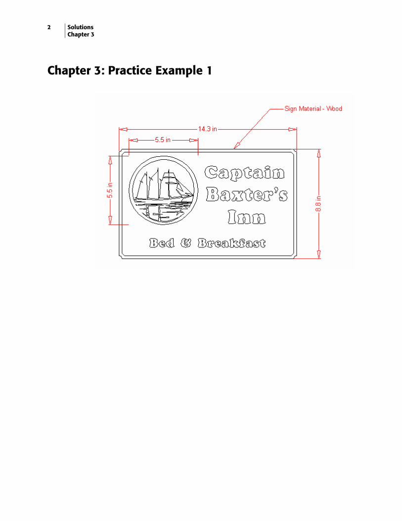
Chapter 3: Practice Example 1
3
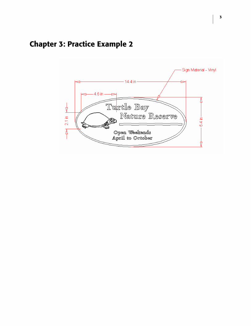
Chapter 3: Practice Example 2

4 Solutions Chapter 4
Chapter 4: Practice Example 1
Creating text
1 Click the Text on the Work Surface tool from the Text fly-out toolbar on the Main toolbar. The pointer turns into an I-beam.
2 Click the Select Font list drop down arrow.
3 Select Burgess Brush from the Select Font list.
4 Double-click the Font Height text box.
5 Type 1 (2.5 cm).
6 Click in the work area.
7 Type Express Trucking.
Creating a shadow
1 Select the text using the Selection tool.
2 Click Tools > Shadow. The Shadow dialog box opens.
3 Choose Drop as the type.
4 In the Parameters box, turn on Distance. The shadow distance is set by X and Y axis.
5 Set the X axis at .15.
6 Set the Y axis at -.15.
7 Click Continue.
Congratulations! You have successfully completed this practice example.
5
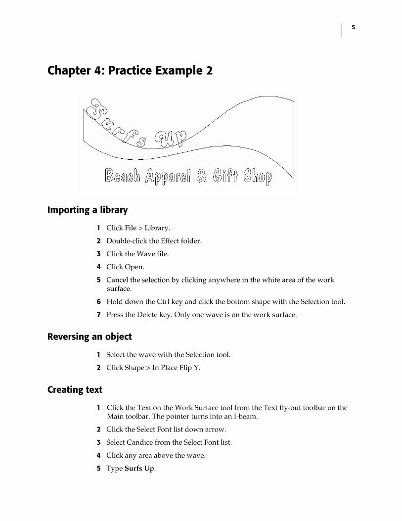
Chapter 4: Practice Example 2
Importing a library
1 Click File > Library.
2 Double-click the Effect folder.
3 Click the Wave file.
4 Click Open.
5 Cancel the selection by clicking anywhere in the white area of the work surface.
6 Hold down the Ctrl key and click the bottom shape with the Selection tool.
7 Press the Delete key. Only one wave is on the work surface.
Reversing an object
1 Select the wave with the Selection tool.
2 Click Shape > In Place Flip Y.
Creating text
1 Click the Text on the Work Surface tool from the Text fly-out toolbar on the Main toolbar. The pointer turns into an I-beam.
2 Click the Select Font list down arrow.
3 Select Candice from the Select Font list.
4 Click any area above the wave.
5 Type Surfs Up.
6 Solutions Chapter 4
6 Click in an area below the wave to set a new line of text.
7 Click the Select Font list down arrow.
8 Select Dom Casual from the Select Font list.
9 Double-click the Font Height text box.
10 Type 1 (2.5 cm).
11 Click Enter.
12 Type Beach Apparel & Gift Shop.
Fitting text to the wave
1 Select Surfs Up with the Selection tool.
2 Hold down the Shift key and click the wave.
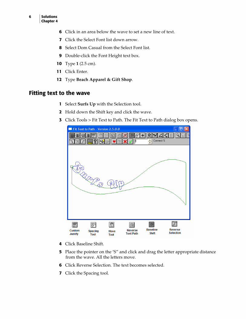
3 Click Tools > Fit Text to Path. The Fit Text to Path dialog box opens.
4 Click Baseline Shift.
5 Place the pointer on the ‘S” and click and drag the letter appropriate distance from the wave. All the letters move.
6 Click Reverse Selection. The text becomes selected.
7 Click the Spacing tool.
7
8 Position the pointer on the “p”, and click and drag toward the right side of the wave. Do not be concerned with the spacing between the “u” and the “p”.
9 Click Cancel Selection.
10 Click the Selection tool.
11 Position the pointer to the upper left side of the “u”. Click and drag a box around the “u” to select it. Make sure all of the “u” falls inside the box or it will not be selected.
12 Click the Move tool, and click and drag the “u” toward the ‘p”.
13 Repeat Steps 11-12 to reposition any letters.
Justifying the design
1 Click the wave with the Selection tool.
2 Hold down the Shift key and click the text, Beach Apparel & Gift Shop.
3 Click Arrange > Justify. The Justify dialog box opens.
4 Click Center Justify.
5 Click OK.
Congratulations! You have successfully completed this practice example.
8 Solutions Chapter 4
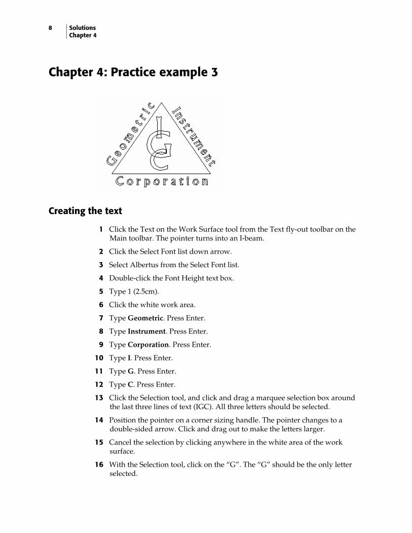
Chapter 4: Practice example 3
Creating the text
1 Click the Text on the Work Surface tool from the Text fly-out toolbar on the Main toolbar. The pointer turns into an I-beam.
2 Click the Select Font list down arrow.
3 Select Albertus from the Select Font list.
4 Double-click the Font Height text box.
5 Type 1 (2.5cm).
6 Click the white work area.
7 Type Geometric. Press Enter.
8 Type Instrument. Press Enter.
9 Type Corporation. Press Enter.
10 Type I. Press Enter.
11 Type G. Press Enter.
12 Type C. Press Enter.
13 Click the Selection tool, and click and drag a marquee selection box around the last three lines of text (IGC). All three letters should be selected.
14 Position the pointer on a corner sizing handle. The pointer changes to a double-sided arrow. Click and drag out to make the letters larger.
15 Cancel the selection by clicking anywhere in the white area of the work surface.
16 With the Selection tool, click on the “G”. The “G” should be the only letter selected.
9
17 Increase the size by positioning the pointer on a corner, and click and drag out. (See the illustration at the beginning of t he exercise.)
18 With the Selection tool, click and drag the “I” to position it on top of the “G”.
19 Repeat the above step for the “C”.
Justifying the letters
1 With the Selection tool, click and drag a marquee box around the letters.
2 Click Arrange > Justify. The Justify dialog box opens.
3 Click Center Justify.
4 Click OK.
Creating a grouping
1 With the letters selected, click Arrange > Group. The three letters are linked together as if one shape.
Creating a triangle
1 Click the Polygon tool from the Construction fly-out toolbar on the Main toolbar.
2 Click on the work area. The Polygon dialog box opens.
3 Change the Number of sides to 3.
4 Turn on Point at Top from the Options box.
5 Click OK.
6 With the Selection tool, size the triangle to fit around the three letters.
Justifying the design
1 Click the triangle with the Selection tool.
2 Hold down the Shift key and click the grouped letters.
3 Click Arrange > Justify. The Justify dialog box opens.
4 Click Center and Middle Justify.
5 Click OK.
6 Cancel the selection by clicking on a white area on the work surface.
7 Click the triangle with the Selection tool.
8 Press the up arrow on the keyboard to move the triangle into a visually centered position. (See the illustration at the beginning of the exercise.)
10 Solutions Chapter 4
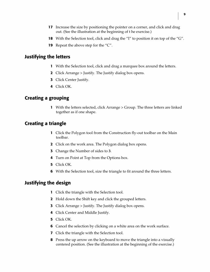
Fitting text to path
1 With the triangle selected, hold down the Shift key and select Geometric.
2 Click Tools > Fit Text to Path. The Fit Text to Path dialog box opens.
3 If the text is located on the inside of the triangle, click the Reverse Text Path button.
4 Click Custom Justify.
5 Click Baseline Shift.
6 Position the hand on any letter. Click and drag the text the appropriate distance from the triangle.
7 Click the Reverse Selection. The text should be highlighted red.
8 Click the Spacing tool.
9 Position the hand on the “C”. Click and drag the text the length of the line.
10 Click the green check mark to return to Composer.
11 Cancel the selection by clicking in the white work area.
12 Click the triangle with the Selection tool.
13 Hold down the Shift key and select Instrument.
14 Click Tools > Fit Text to Path. The Fit Text to Path dialog box opens.
15 If the text is located on the inside of the triangle, click the Reverse Text Path button.
11
16 Click Custom Justify.
17 Click Baseline Shift.
18 Position the hand on any letter. Click and drag the text the appropriate distance from the triangle.
19 Click Reverse Selection. The text should be highlighted red.
20 Click the Spacing tool.
21 Position the hand on the last “T”. Click and drag the text the length of the line.
22 Click the Move tool.
23 Position the hand anywhere on the text. Click and drag the text to the right-hand side.
24 Click the green check mark to return to Composer.
25 Cancel the selection by clicking in the white work area.
26 Click the triangle to select it.
27 Hold down the Shift key and select Corporation.
28 Click Tools > Fit Text to Path. The Fit Text to Path dialog box opens.
29 If the text is located on the outside of the triangle, click the Reverse Text Path button.
30 Click Custom Justify.
31 Click Baseline Shift.
32 Position the hand on any letter. Click and drag the text through the line of the triangle to the appropriate position.
33 Click Reverse Selection. The text should be highlighted red.
34 Click the Spacing tool.
35 Position the hand on the “N”. Click and drag the text the length of the line.
36 Click the green check mark to return to Composer.
Congratulations! You have successfully completed this practice example.
12 Solutions Chapter 5
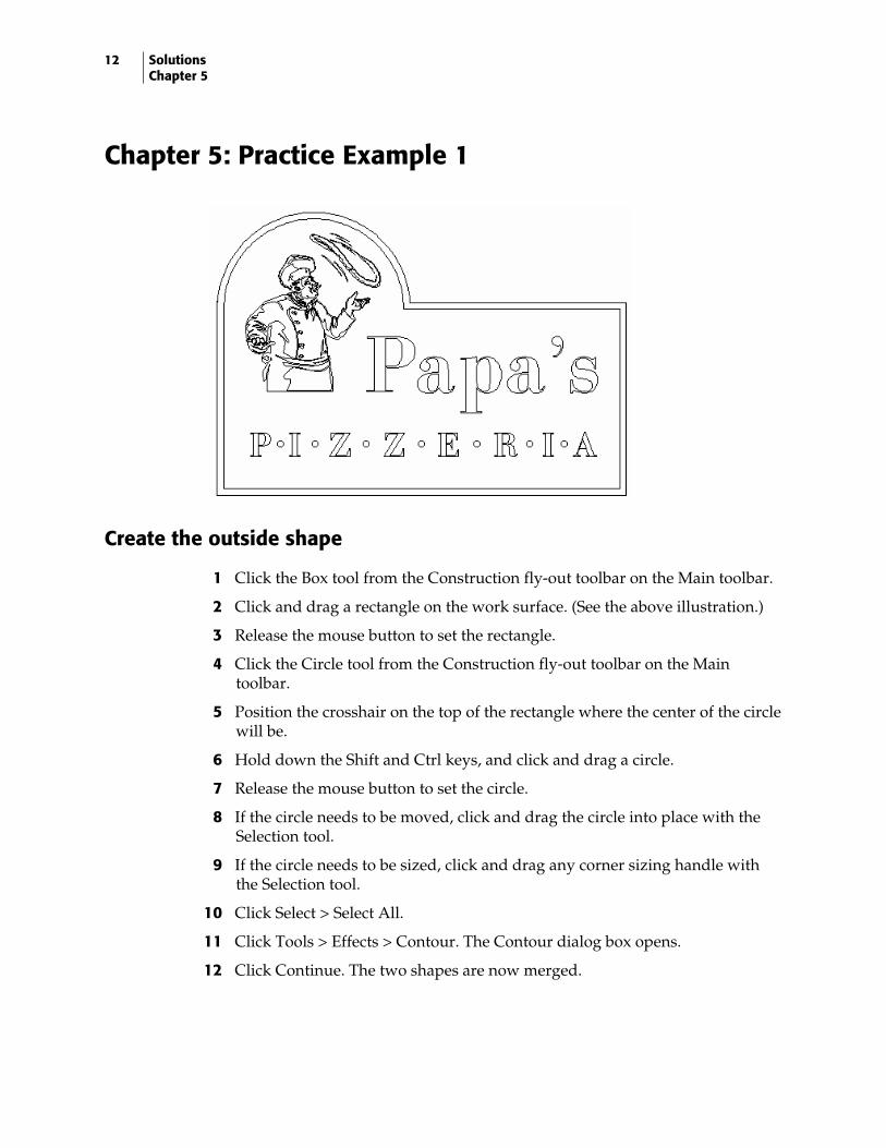
Chapter 5: Practice Example 1
Create the outside shape
1 Click the Box tool from the Construction fly-out toolbar on the Main toolbar.
2 Click and drag a rectangle on the work surface. (See the above illustration.)
3 Release the mouse button to set the rectangle.
4 Click the Circle tool from the Construction fly-out toolbar on the Main toolbar.
5 Position the crosshair on the top of the rectangle where the center of the circle will be.
6 Hold down the Shift and Ctrl keys, and click and drag a circle.
7 Release the mouse button to set the circle.
8 If the circle needs to be moved, click and drag the circle into place with the Selection tool.
9 If the circle needs to be sized, click and drag any corner sizing handle with the Selection tool.
10 Click Select > Select All.
11 Click Tools > Effects > Contour. The Contour dialog box opens.
12 Click Continue. The two shapes are now merged.
13
Placing the library
1 Click File > Library.
2 Double-click the Sampler2 folder.
3 Choose the Cook file, and click Open.
4 Move the graphic by clicking and dragging it into position with the Selection tool.
5 If you need to size the graphic, click and drag any corner sizing handle.
6 Click Shape > In Place Flip X.
Adding the text
1 Click the Text on the Work Surface tool from the Main toolbar. The pointer turns into an I-beam.
2 Click the Select Font list down arrow.
3 Select Bodoni Bold from the Select Font list.
4 Click the work surface.
5 Type Papa’s. Press Enter.
6 Type PIZZERIA.
7 Click the Character Spacing tool.
8 Position the pointer in one of the spacing handles and drag out.
9 Turn off the Character Spacing tool by clicking the icon again.
10 Click the Selection tool, and move each line of text to the appropriate location.
11 Using the Selection tool, size the text by clicking and dragging one of the corner sizing handles.
Creating and position the dots
1 Click the Circle tool from the Construction fly-out toolbar on the Main toolbar.
2 Position the crosshair between the “P” and the “I” according to the example.
3 Hold down the Shift and Ctrl keys, and click and drag a circle.
4 Click the Selection tool to select the circle.
5 Click Edit > Copy, then Edit > Paste.
6 With the Selection tool, move the circle into location.
7 Repeat Steps 5 and 6 for all the circles.
14 Solutions Chapter 5
Justifying the circles
1 Click the first circle with the Selection tool.
2 Hold down the Shift key and click the other circles.
3 Click Arrange > Justify. The Justify dialog box opens.
4 Click the Middle Justify icon.
5 Click OK.
Creating the outline
1 Click the outside, contoured shape with the Selection tool.
2 Click Tools > Outline. The Outline dialog box opens.
3 Set the Outline Distance at .5 (2.7 mm). This number may have to be changed depending on the size of the outside shape.
4 Turn off Hide Originals if a check mark is present.
5 Click OK.
6 If the outline is not the correct size, double-click the outline with the Selection tool. The Outline dialog box opens.
7 Change the Outline Distance to a larger or smaller number.
8 Click OK.
9 Repeat Steps 6-8 if the size is still not correct.
Congratulations! You have successfully completed this practice example.
15
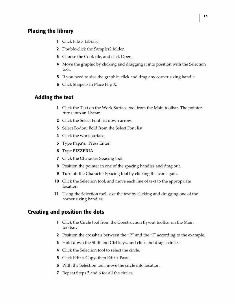
Chapter 5: Practice Example 2
Creating the text
1 Click the Text on the Work Surface tool from the Main toolbar. The pointer turns into an I-beam.
2 Click the Select Font list down arrow.
3 Select Franklin Gothic from the Select Font list.
4 Click on the work surface.
5 Click the Left Justify icon on the Text toolbar.
6 Type D.
7 Press Enter.
8 Type Dalton.
9 Press Enter.
10 Type Publishing.
11 Press Enter.
12 Type Company.
13 Click the Character Spacing tool on the Text toolbar.
14 Position the pointer in one of the spacing handles and drag out.
15 Turn off the Character Spacing tool by clicking the icon.
16 Press the up arrow on the keyboard to position the cursor on the next line of text.
17 Repeat Steps 13-16 for the next two lines of text.
18 Click the Selection tool.
16 Solutions Chapter 5
19 Move the “D” to the left side of the text by clicking on a line and dragging it into position.
20 Using the Selection tool, size the letter by clicking and dragging one of the corner sizing handles. (See the illustration)
Placing a guideline
1 Position the pointer on the angle symbol located in the upper left corner of the work surface. Click and drag a blue guideline onto the work surface. Part of the guideline will remain in the corner until it is anchored.
2 Position the crosshair at a point on the outer line of the “D” where the line divides the solid from the stripped portion of the “D”. Release the mouse button to set the pivot point. (See the illustration at the beginning of the exercise).
3 Move the crosshair to the opposite point on the “D” to complete the line, and click to set the guideline.
Editing the text
1 With the “D” selected, click Text > Remove Text Smart Edit > Normal Text.
2 Click the Detail Edit icon from the Main toolbar. The Detail Edit toolbar opens.
3 Click the Slice and Dice tool from the Detail Edit toolbar. The pointer turns into a knife.
4 Click Layout > Snap to Guidelines.
5 Position the white tip of the knife on the blue guideline outside the “D”.
6 Click and drag along the guideline all the way through the “D”. Release the mouse button to set the line.
Adding Stripes
1 Click the Selection tool.
2 Cancel the selection by clicking on the white area of the work surface.
3 Hold down the Ctrl key, click the half of the “D” that will be striped.
4 Click Tools > Effects > Stripes.
5 Turn on Fixed.
6 Set the number of stripes to 8.
7 Turn on Equal.
8 Click Continue.
17
Removing the guideline
1 Click Layout > Remove Guidelines.
Creating the rectangle
1 Click the Box tool from the Construction fly-out toolbar on the Main toolbar.
2 Click and drag a rectangle around the design.
3 Size the rectangle with the Selection tool by clicking and dragging a sizing handle.
Congratulations! You have successfully completed this practice example.

18 Solutions Rainbow Springs
Rainbow Springs: Practice Exercises
The following exercises relate to the 5 Steps described in the OMEGA Learning Guide, Chapter 11. The plot (PLT) files are located in C:\Jobs\Learning folder. If you do not have these files, they can be downloaded from the Gerber web site.
Open each file and fix the errors so that they will print correctly.
Rainbow1.plt
1 Click File > Open and navigate to C:\Jobs\Learning folder.
2 Choose Rainbow1.plt and click Open.
3 Click View > Filled > Output View to view the job as if were printed, cut on the plotter, and weeded.
4 Click View > Filled > Design View to display the job filled with colors.
5 Note that in Filled mode, the grey of the background vinyl shows through the text and clip art. In wireframe mode the text and clip art have green wireframes indicating cut shapes.
19
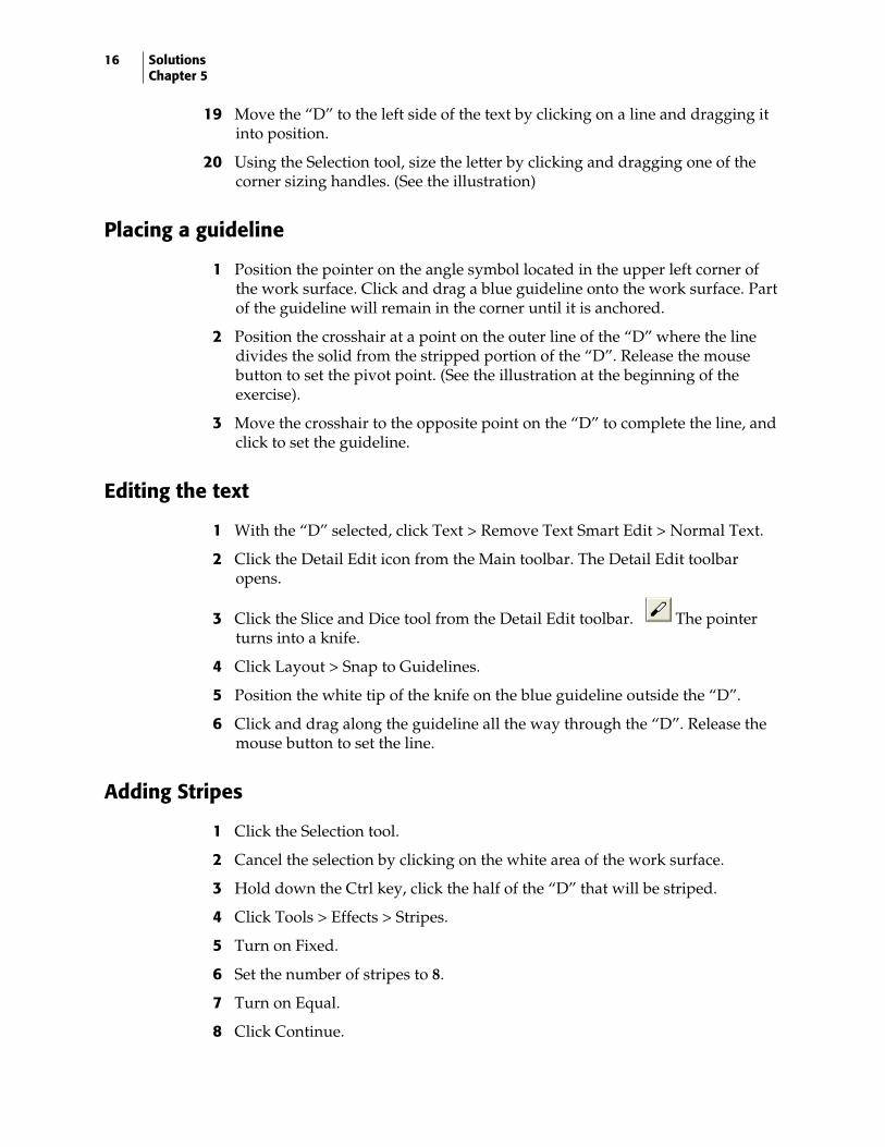
6 Select the text and the clip art and click Arrange > Cuts Off, or click the Cuts Off icon in the Arrange toolbar. The job should display correctly as shown in the following illustration.
Rainbow2.plt
1 Click File > Open and navigate to C:\Jobs\Learning folder.
2 Choose Rainbow2.plt and click Open.
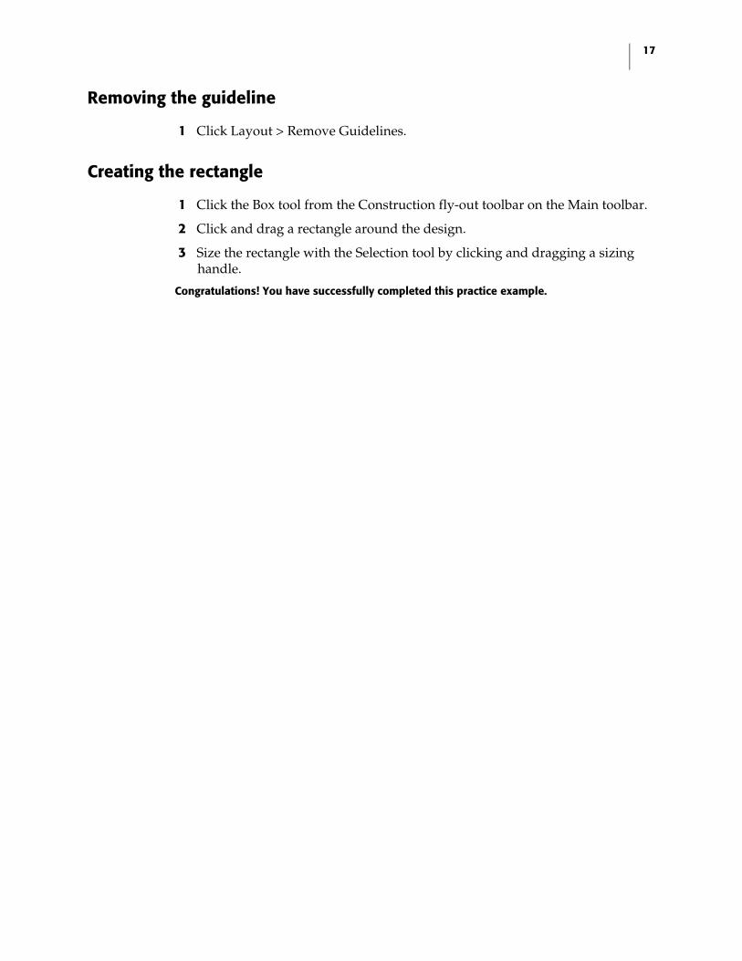
3 Click View > Filled > Output View to view the job as if were printed, cut on the plotter, and weeded.
4 Note that the text and clip art do not display correctly.
5 Select the text and click Arrange > Combine On or click the Combine On icon on the Arrange toolbar.
6 Select the clip art and click Arrange > Combine On or click the Combine On icon on the Arrange toolbar.
Note: You must select and combine the text and clip art separately because they have different fills. If you select both the text and the clip art and then combine them, Composer attempts to make them the same style (fill color).
7 The job should display correctly as shown in the following illustration.
20 Solutions Rainbow Springs
Rainbow3.plt
1 Click File > Open and navigate to C:\Jobs\Learning folder.
2 Choose Rainbow3.plt and click Open.
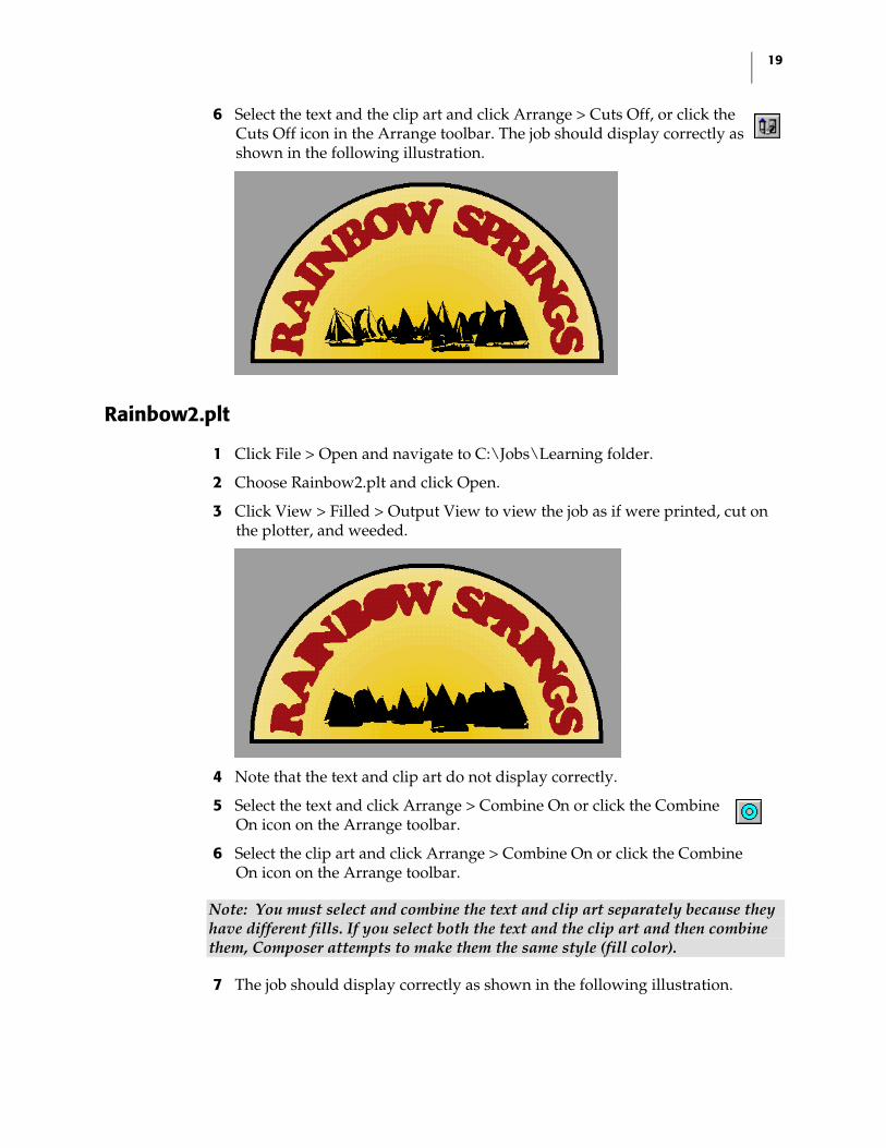
3 Click View > Filled > Output View to view the job as if were printed, cut on the plotter, and weeded.
4 Note that the job appears to be layered incorrectly with the bottom layer in front.
5 Click View > Cut Print Colors to see all of the shapes in the job.
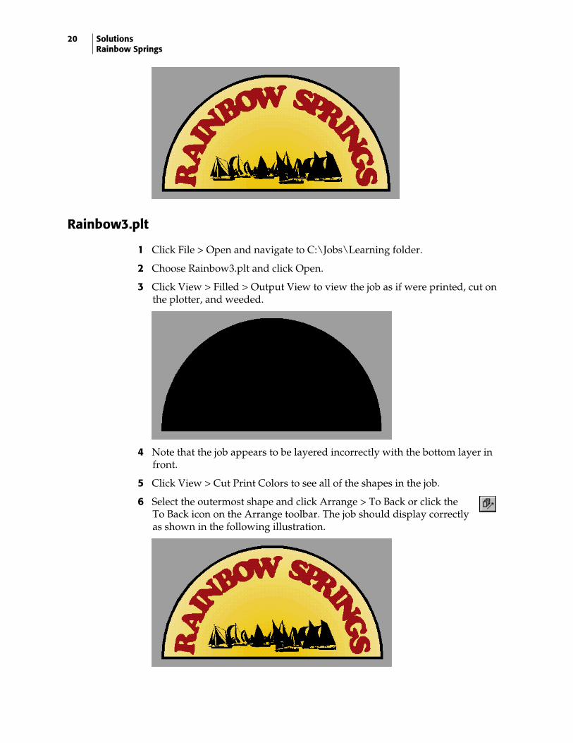
6 Select the outermost shape and click Arrange > To Back or click the To Back icon on the Arrange toolbar. The job should display correctly as shown in the following illustration.
21
Rainbow4.plt
1 Click File > Open and navigate to C:\Jobs\Learning folder.
2 Choose Rainbow3.plt and click Open.
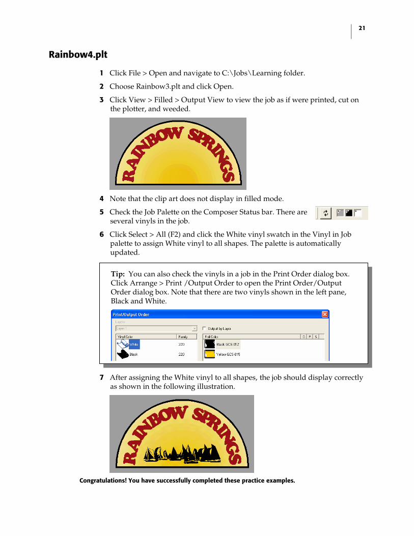
3 Click View > Filled > Output View to view the job as if were printed, cut on the plotter, and weeded.
4 Note that the clip art does not display in filled mode.
5 Check the Job Palette on the Composer Status bar. There are several vinyls in the job.
6 Click Select > All (F2) and click the White vinyl swatch in the Vinyl in Job palette to assign White vinyl to all shapes. The palette is automatically updated.
7 After assigning the White vinyl to all shapes, the job should display correctly as shown in the following illustration.
Congratulations! You have successfully completed these practice examples.
Tip: You can also check the vinyls in a job in the Print Order dialog box. Click Arrange > Print /Output Order to open the Print Order/Output Order dialog box. Note that there are two vinyls shown in the left pane, Black and White.
22 Solutions Final Exam
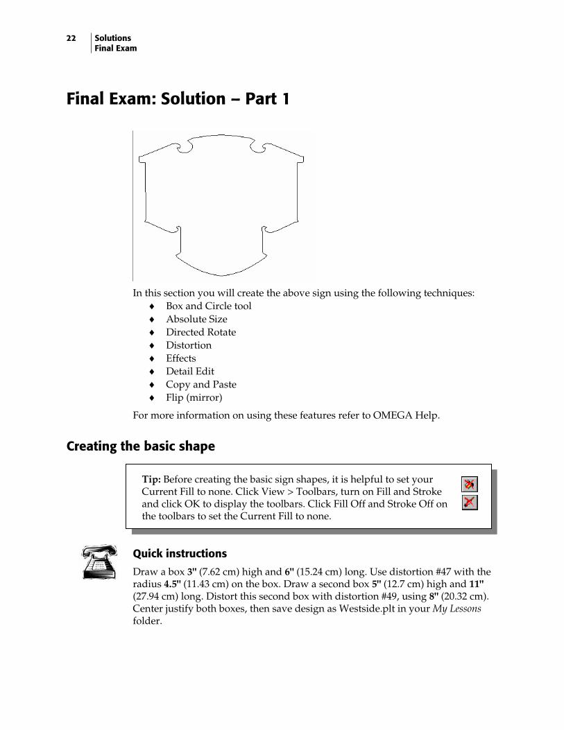
Final Exam: Solution – Part 1
In this section you will create the above sign using the following techniques:
♦ Box and Circle tool ♦ Absolute Size ♦ Directed Rotate ♦ Distortion ♦ Effects ♦ Detail Edit ♦ Copy and Paste ♦ Flip (mirror)
For more information on using these features refer to OMEGA Help.
Creating the basic shape
Quick instructions
Draw a box 3" (7.62 cm) high and 6" (15.24 cm) long. Use distortion #47 with the radius 4.5" (11.43 cm) on the box. Draw a second box 5" (12.7 cm) high and 11" (27.94 cm) long. Distort this second box with distortion #49, using 8" (20.32 cm). Center justify both boxes, then save design as Westside.plt in your My Lessons folder.
Tip: Before creating the basic sign shapes, it is helpful to set your Current Fill to none. Click View > Toolbars, turn on Fill and Stroke and click OK to display the toolbars. Click Fill Off and Stroke Off on the toolbars to set the Current Fill to none.

23
Detailed instructions
1 Select the Box tool from the Construction toolbar. The pointer changes to a crosshair.
2 Draw a box approximately 3" (7.62 cm) high x 6" (15.24 cm) long.
3 Click the Selection tool, then click Shape > Absolute Size to open the Absolute Size dialog box and resize the box. Enter the following settings: ♦ Turn on Non-uniform in Size Type. ♦ Enter 3" (7.62 cm) in Height. ♦ Enter 6" (15.24 cm) in Length.
4 Click OK to resize the box.
5 Select the box with the Selection tool, then click Tools > Distortion to open the Distortion dialog box to change the shape of the box.
6 Enter 47 in the Type box to select the distortion: 47 Convex Arch Bottom. Click Continue to open the Modify Parameters dialog box.
7 Enter 4.5" (11.43 cm) in the R box and click OK. The box is now 4.162" (10.57 cm) high x 6" (15.24 cm) long and has a curved bottom. This will be the bottom portion of the sign.
8 Select the Box tool and draw a box approximately 5" (12.7 cm) high x 11" (27.94 cm) long.
9 Click Shape > Absolute Size to open the Absolute Size dialog box and resize the box. Enter the following settings:
♦ Turn on Non-uniform in Size Type. ♦ Enter 5" (12.7 cm) in Height. ♦ Enter 11" (27.94 cm) in Length.
10 Click OK to resize the box.
11 Click the Selection tool to select the box, then click Tools > Distortion to open the Distortion dialog box to change the shape of the box.
12 Enter 49 in the Type box to select the distortion: 49 Convex Arch Both. Click Continue to open the Modify Parameters dialog box.
13 Enter 8" (20.32 cm) in H2 (R will now be 10.8333 (27.50 cm)) and click OK to return to the work surface. The box is now 8.024" (20.38 cm) high x 11" (27.94 cm) long.
24 Solutions Final Exam
14 Use the Selection tool to move the shapes into the approximate position shown in the previous illustration.
15 Use the Selection tool to first select the larger shape, then select the smaller shape while holding down the Shift key.
16 Click Arrange > Justify and click the Center justify in Horizontal to position the shape precisely.
17 Click File > Save and save your design as Westside.plt in your My Lessons folder.
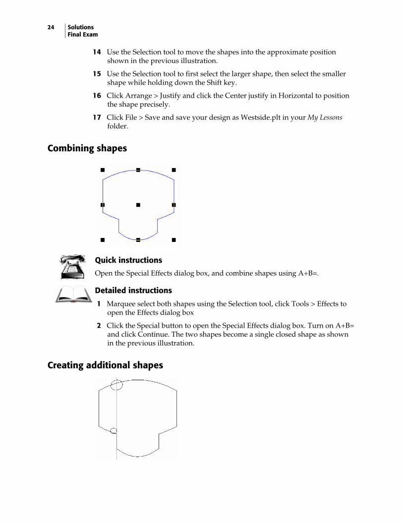
Combining shapes
Quick instructions
Open the Special Effects dialog box, and combine shapes using A+B=.
Detailed instructions
1 Marquee select both shapes using the Selection tool, click Tools > Effects to open the Effects dialog box
2 Click the Special button to open the Special Effects dialog box. Turn on A+B= and click Continue. The two shapes become a single closed shape as shown in the previous illustration.
Creating additional shapes

25
Quick instructions
Draw a oval 1.3" (3.30 cm) high and 1.7" (4.31 cm) long. Rotate the oval 18° and place along the top left edge of the previously created sign blank. Draw a second oval 0.75" (1.90 cm) high and 0.9" (2.28 cm).
Detailed instructions
1 Select the Circle tool from the Construction toolbar.
2 Draw an oval approximately 1" (2.54 cm) high and 2" long (5.08 cm).
3 Click the Selection tool to select the oval shape then, click Shape > Absolute Size to open the Absolute Size dialog box to resize the oval. Enter the following settings:
♦ Turn on Non-uniform in Size Type. ♦ Enter 1.3" (3.30 cm) in Height. ♦ Enter 1.7" (4.31 cm) in Length.
4 Click OK to resize the oval, then click Shape > Directed Rotate to open the Directed Rotate dialog box. Enter 18 in the Angle box and click OK. Click the center handle of the shape to locate the rotation point.
5 Use the Selection tool to move the oval into the approximate position shown in the previous illustration. You can add a guideline as shown to assist in locating the oval correctly.
6 Click the Circle tool from the Construction toolbar and draw an oval approximately 0.75" (1.90 cm) high x 1" (2.54 cm) long.
7 Click the Selection tool to select the new oval shape, then click Shape > Absolute Size to open the Absolute Size dialog box and resize the oval. Enter the following settings:
♦ Turn on Non-uniform in Size Type. ♦ Enter 0.75" (19.05 mm) in Height. ♦ Enter 0.9" (22.86 mm) in Length.
8 Click OK to resize the oval.
9 Use the Selection tool to move the oval into the approximate position shown in the previous illustration.
26 Solutions Final Exam
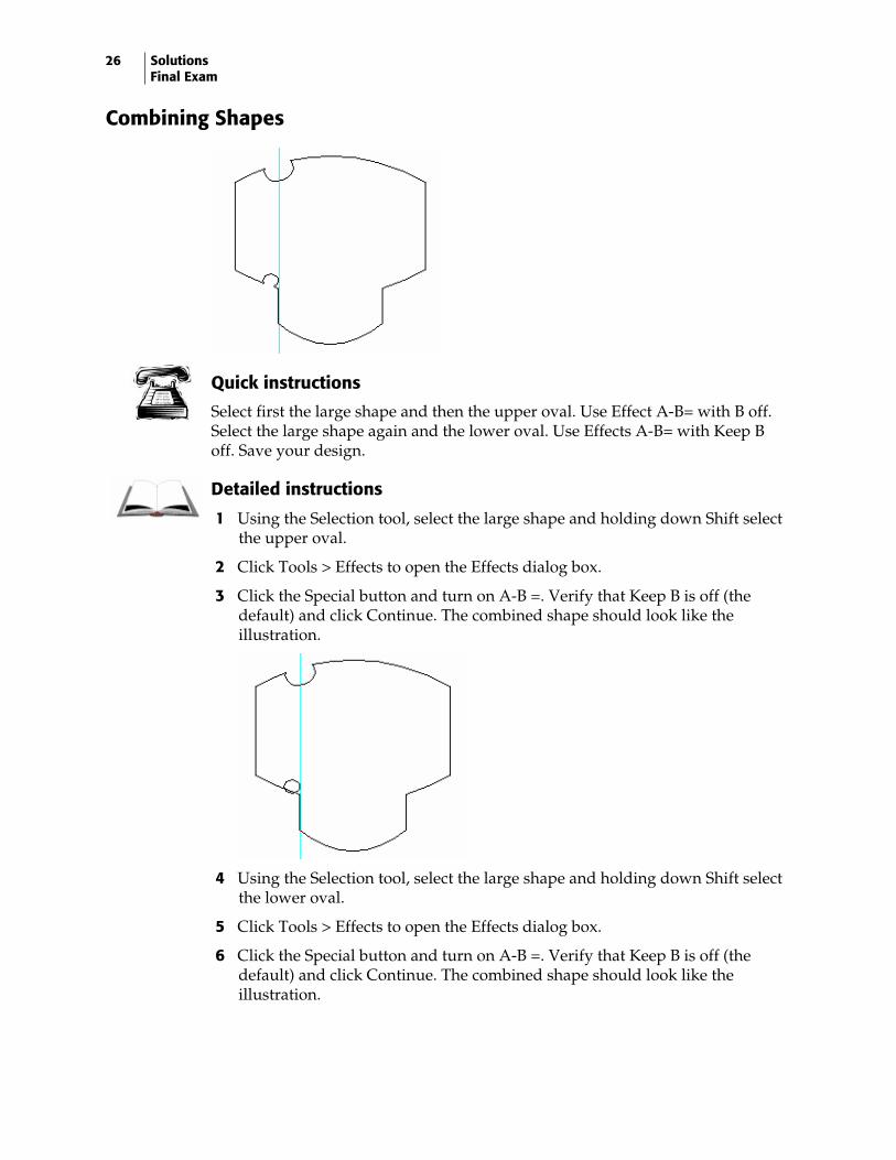
Combining Shapes
Quick instructions
Select first the large shape and then the upper oval. Use Effect A-B= with B off. Select the large shape again and the lower oval. Use Effects A-B= with Keep B off. Save your design.
Detailed instructions
1 Using the Selection tool, select the large shape and holding down Shift select the upper oval.
2 Click Tools > Effects to open the Effects dialog box.
3 Click the Special button and turn on A-B =. Verify that Keep B is off (the default) and click Continue. The combined shape should look like the illustration.
4 Using the Selection tool, select the large shape and holding down Shift select the lower oval.
5 Click Tools > Effects to open the Effects dialog box.
6 Click the Special button and turn on A-B =. Verify that Keep B is off (the default) and click Continue. The combined shape should look like the illustration.
27
Detail editing the shape
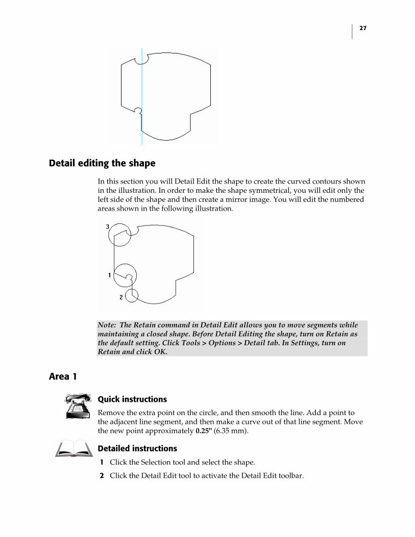
In this section you will Detail Edit the shape to create the curved contours shown in the illustration. In order to make the shape symmetrical, you will edit only the left side of the shape and then create a mirror image. You will edit the numbered areas shown in the following illustration.
Note: The Retain command in Detail Edit allows you to move segments while maintaining a closed shape. Before Detail Editing the shape, turn on Retain as the default setting. Click Tools > Options > Detail tab. In Settings, turn on Retain and click OK.
Area 1
Quick instructions
Remove the extra point on the circle, and then smooth the line. Add a point to the adjacent line segment, and then make a curve out of that line segment. Move the new point approximately 0.25" (6.35 mm).
Detailed instructions
1 Click the Selection tool and select the shape.
2 Click the Detail Edit tool to activate the Detail Edit toolbar.
28 Solutions Final Exam
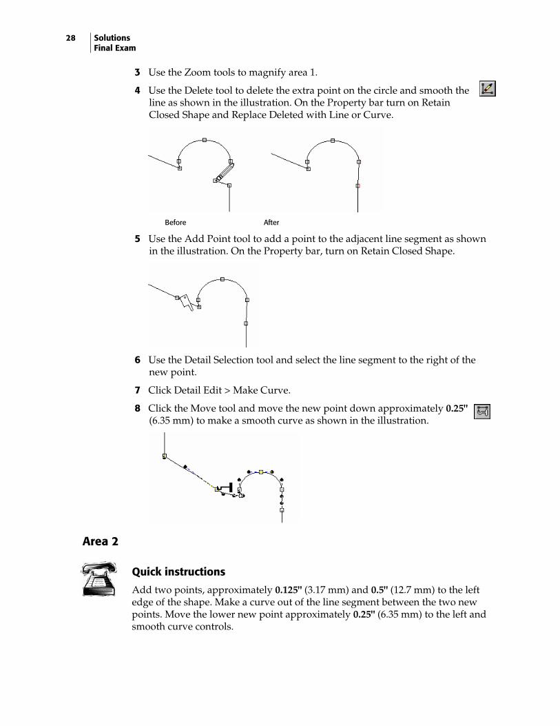
3 Use the Zoom tools to magnify area 1.
4 Use the Delete tool to delete the extra point on the circle and smooth the line as shown in the illustration. On the Property bar turn on Retain Closed Shape and Replace Deleted with Line or Curve.
Before After
5 Use the Add Point tool to add a point to the adjacent line segment as shown in the illustration. On the Property bar, turn on Retain Closed Shape.
6 Use the Detail Selection tool and select the line segment to the right of the
new point.
7 Click Detail Edit > Make Curve.
8 Click the Move tool and move the new point down approximately 0.25" (6.35 mm) to make a smooth curve as shown in the illustration.
Area 2
Quick instructions
Add two points, approximately 0.125" (3.17 mm) and 0.5" (12.7 mm) to the left edge of the shape. Make a curve out of the line segment between the two new points. Move the lower new point approximately 0.25" (6.35 mm) to the left and smooth curve controls.
29
Detailed instructions
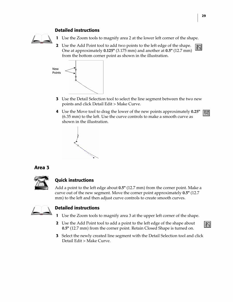
1 Use the Zoom tools to magnify area 2 at the lower left corner of the shape.
2 Use the Add Point tool to add two points to the left edge of the shape. One at approximately 0.125" (3.175 mm) and another at 0.5" (12.7 mm) from the bottom corner point as shown in the illustration.
3 Use the Detail Selection tool to select the line segment between the two new points and click Detail Edit > Make Curve.
4 Use the Move tool to drag the lower of the new points approximately 0.25" (6.35 mm) to the left. Use the curve controls to make a smooth curve as shown in the illustration.
Area 3
Quick instructions
Add a point to the left edge about 0.5" (12.7 mm) from the corner point. Make a curve out of the new segment. Move the corner point approximately 0.5" (12.7 mm) to the left and then adjust curve controls to create smooth curves.
Detailed instructions
1 Use the Zoom tools to magnify area 3 at the upper left corner of the shape.
2 Use the Add Point tool to add a point to the left edge of the shape about 0.5" (12.7 mm) from the corner point. Retain Closed Shape is turned on.
3 Select the newly created line segment with the Detail Selection tool and click Detail Edit > Make Curve.
New Points
30 Solutions Final Exam
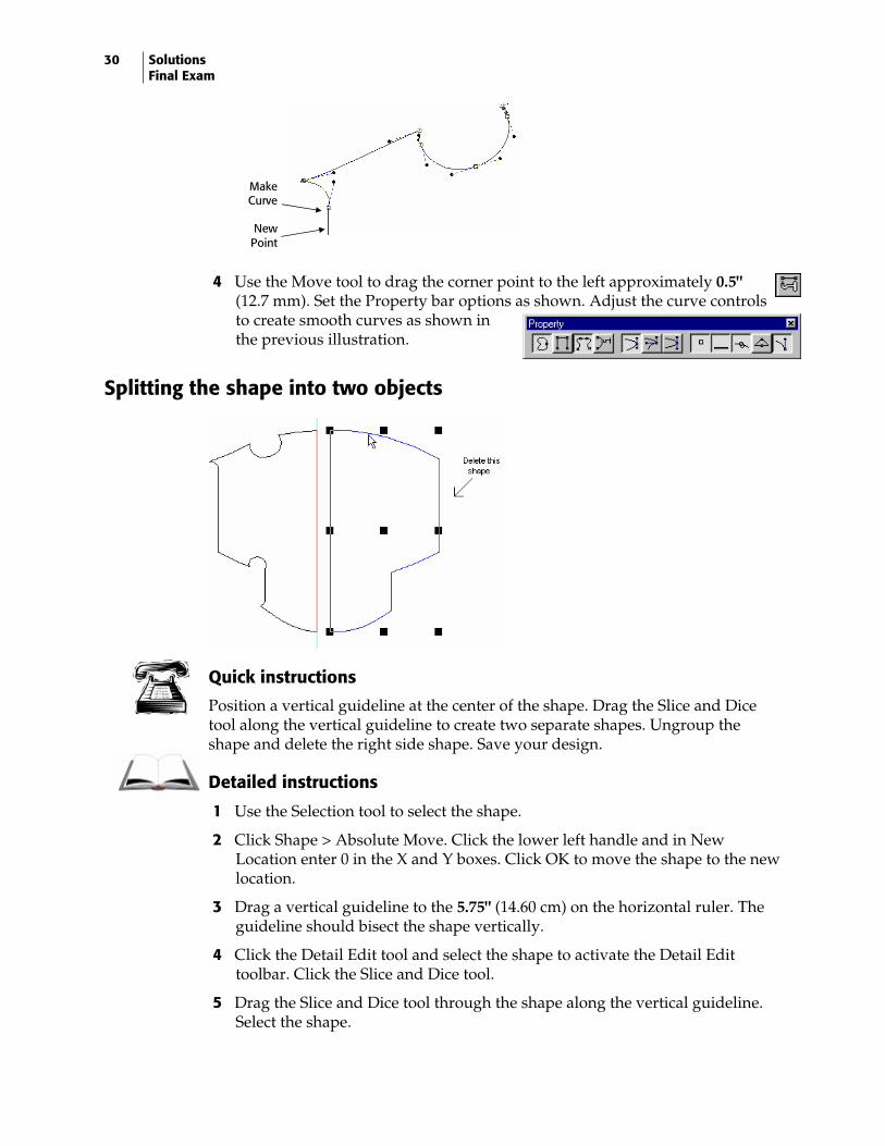
4 Use the Move tool to drag the corner point to the left approximately 0.5" (12.7 mm). Set the Property bar options as shown. Adjust the curve controls to create smooth curves as shown in the previous illustration.
Splitting the shape into two objects
Quick instructions
Position a vertical guideline at the center of the shape. Drag the Slice and Dice tool along the vertical guideline to create two separate shapes. Ungroup the shape and delete the right side shape. Save your design.
Detailed instructions
1 Use the Selection tool to select the shape.
2 Click Shape > Absolute Move. Click the lower left handle and in New Location enter 0 in the X and Y boxes. Click OK to move the shape to the new location.
3 Drag a vertical guideline to the 5.75" (14.60 cm) on the horizontal ruler. The guideline should bisect the shape vertically.
4 Click the Detail Edit tool and select the shape to activate the Detail Edit toolbar. Click the Slice and Dice tool.
5 Drag the Slice and Dice tool through the shape along the vertical guideline. Select the shape.
Make Curve
New Point
31
6 Click Arrange > Ungroup to create two separate shapes. Click the right shape and delete it.
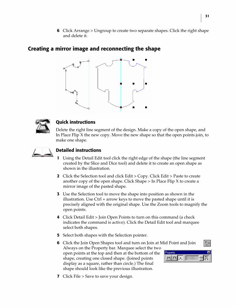
Creating a mirror image and reconnecting the shape
Quick instructions
Delete the right line segment of the design. Make a copy of the open shape, and In Place Flip X the new copy. Move the new shape so that the open points join, to make one shape.
Detailed instructions
1 Using the Detail Edit tool click the right edge of the shape (the line segment created by the Slice and Dice tool) and delete it to create an open shape as shown in the illustration.
2 Click the Selection tool and click Edit > Copy. Click Edit > Paste to create another copy of the open shape. Click Shape > In Place Flip X to create a mirror image of the pasted shape.
3 Use the Selection tool to move the shape into position as shown in the illustration. Use Ctrl + arrow keys to move the pasted shape until it is precisely aligned with the original shape. Use the Zoom tools to magnify the open points.
4 Click Detail Edit > Join Open Points to turn on this command (a check indicates the command is active). Click the Detail Edit tool and marquee select both shapes.
5 Select both shapes with the Selection pointer.
6 Click the Join Open Shapes tool and turn on Join at Mid Point and Join Always on the Property bar. Marquee select the two open points at the top and then at the bottom of the shape, creating one closed shape. (Joined points display as a square, rather than circle.) The final shape should look like the previous illustration.
7 Click File > Save to save your design.

32 Solutions Final Exam
Final Exam: Solution – Part 2
In this section you will create the above sign using the following techniques:
♦ Multiple outlines ♦ Absolute Size ♦ Creating mirror images ♦ Filling shapes with color
For more information on using these features refer to OMEGA Help.
Outlining the shape
Quick instructions
In outline Pass 1, add two round outlines to the shape at -0.100" (2.54 mm) outline distance. In Pass 2 add 1 round outline at 0.300" (7.62 mm) outline distance. Size the entire design to 11" (27.94 cm) high and 13" (33.02 cm) long. Save your design.
33
Detailed instructions
1 Select the shape using the Selection tool. Click Tools > Outline to open the Outline dialog box.
2 Enter the following settings for Pass 1: ♦ Turn on Round. ♦ Enter 2 in Number of Outlines. ♦ Enter –0.100" (-2.54 mm) in Outline Distance. (Negative values create outlines
inside the original shape.)
3 Enter the following settings in Pass 2: ♦ Turn on Round. ♦ Enter 1 in Number of Outlines. ♦ Enter 0.300" (7.62 mm) in Outline Distance.
4 Click OK to create the outlines. Marquee select all the shapes. Click Shape > Absolute Size to open the Absolute Size dialog box.
5 Turn on Non-uniform and enter 11" (27.94 cm) in Height and 13" (33.02 cm) in Length. Click OK to resize the shapes.
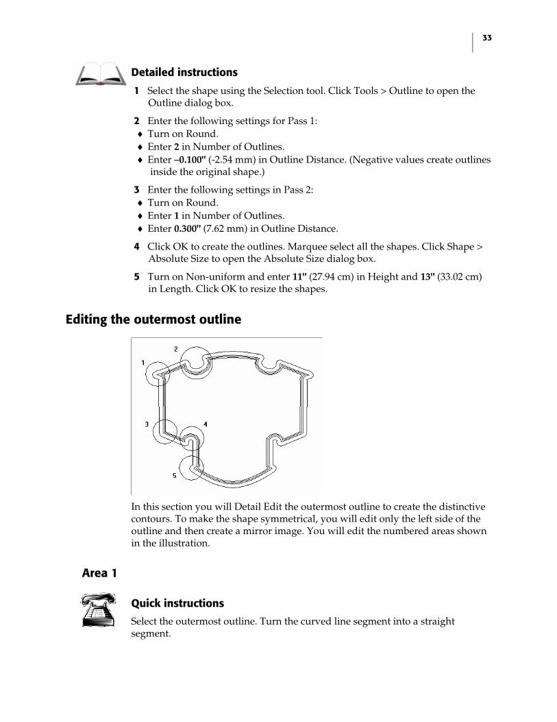
Editing the outermost outline
In this section you will Detail Edit the outermost outline to create the distinctive contours. To make the shape symmetrical, you will edit only the left side of the outline and then create a mirror image. You will edit the numbered areas shown in the illustration.
Area 1
Quick instructions
Select the outermost outline. Turn the curved line segment into a straight segment.
34 Solutions Final Exam
Detailed instructions
1 Use the Zoom tools to magnify area 1 in the upper left corner of the shape.
2 Use the Selection tool to select only the outermost outline. Select the Detail Edit tool to activate the Detail Edit toolbar.
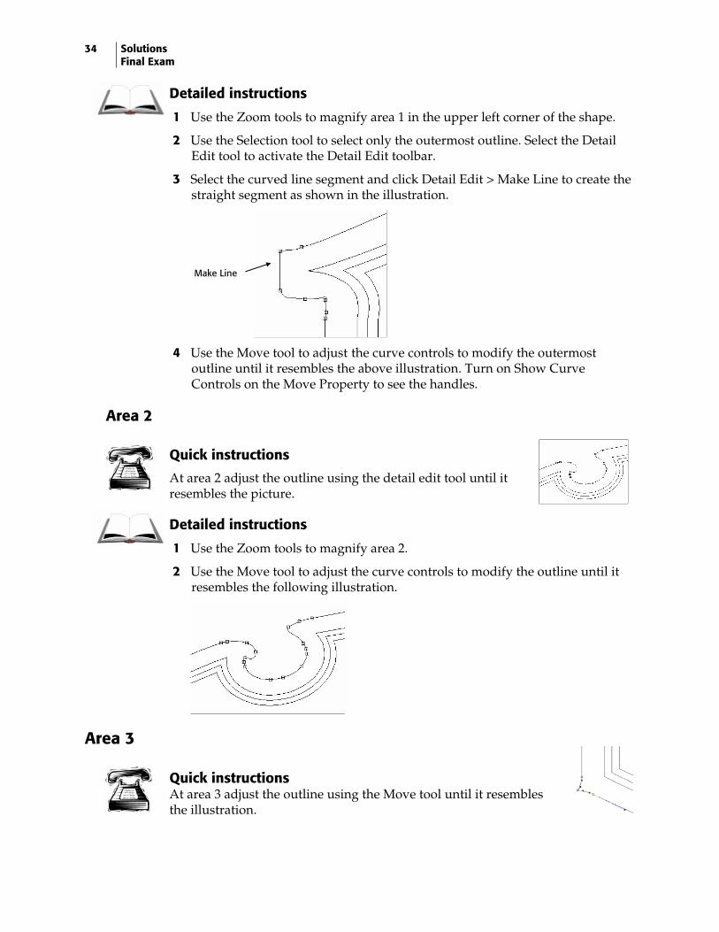
3 Select the curved line segment and click Detail Edit > Make Line to create the straight segment as shown in the illustration.
4 Use the Move tool to adjust the curve controls to modify the outermost outline until it resembles the above illustration. Turn on Show Curve Controls on the Move Property to see the handles.
Area 2
Quick instructions
At area 2 adjust the outline using the detail edit tool until it resembles the picture.
Detailed instructions
1 Use the Zoom tools to magnify area 2.
2 Use the Move tool to adjust the curve controls to modify the outline until it resembles the following illustration.
Area 3
Quick instructions At area 3 adjust the outline using the Move tool until it resembles the illustration.
Make Line
35
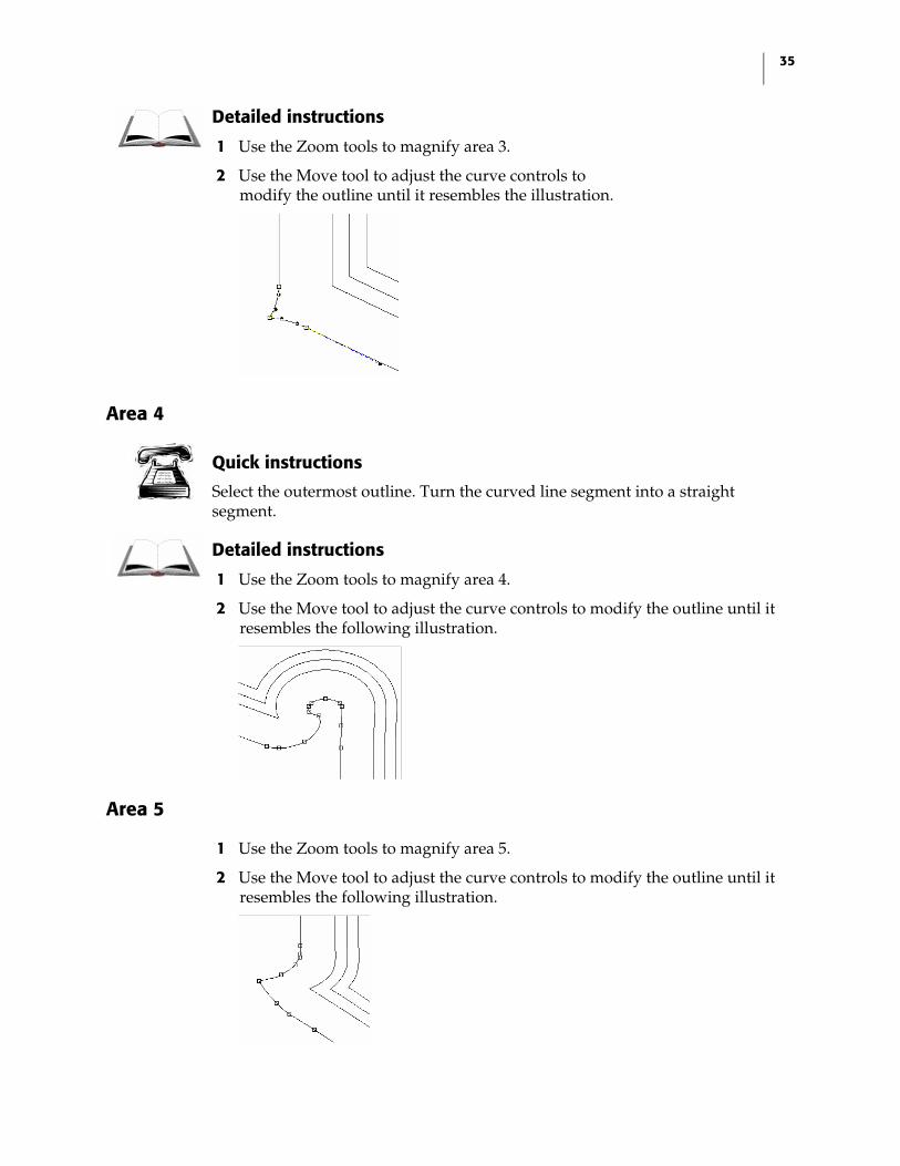
Detailed instructions
1 Use the Zoom tools to magnify area 3.
2 Use the Move tool to adjust the curve controls to modify the outline until it resembles the illustration.
Area 4
Quick instructions
Select the outermost outline. Turn the curved line segment into a straight segment.
Detailed instructions
1 Use the Zoom tools to magnify area 4.
2 Use the Move tool to adjust the curve controls to modify the outline until it resembles the following illustration.
Area 5
1 Use the Zoom tools to magnify area 5.
2 Use the Move tool to adjust the curve controls to modify the outline until it resembles the following illustration.
36 Solutions Final Exam
Creating a mirror image and reconnecting the outline
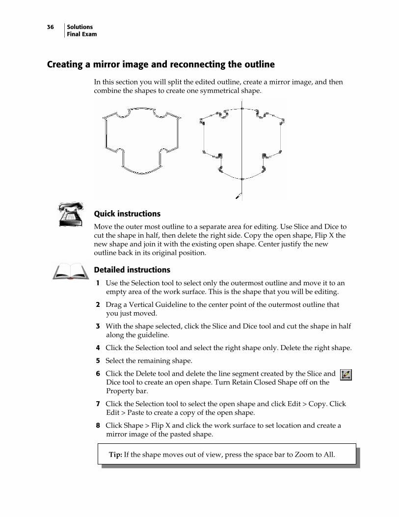
In this section you will split the edited outline, create a mirror image, and then combine the shapes to create one symmetrical shape.
Quick instructions
Move the outer most outline to a separate area for editing. Use Slice and Dice to cut the shape in half, then delete the right side. Copy the open shape, Flip X the new shape and join it with the existing open shape. Center justify the new outline back in its original position.
Detailed instructions
1 Use the Selection tool to select only the outermost outline and move it to an empty area of the work surface. This is the shape that you will be editing.
2 Drag a Vertical Guideline to the center point of the outermost outline that you just moved.
3 With the shape selected, click the Slice and Dice tool and cut the shape in half along the guideline.
4 Click the Selection tool and select the right shape only. Delete the right shape.
5 Select the remaining shape.
6 Click the Delete tool and delete the line segment created by the Slice and Dice tool to create an open shape. Turn Retain Closed Shape off on the Property bar.
7 Click the Selection tool to select the open shape and click Edit > Copy. Click Edit > Paste to create a copy of the open shape.
8 Click Shape > Flip X and click the work surface to set location and create a mirror image of the pasted shape.
Tip: If the shape moves out of view, press the space bar to Zoom to All.
37
9 Use the Selection tool to move the shape into position to create a symmetrical shape. Use Ctrl + arrow keys to move the pasted shape until it is precisely aligned with the original shape. Use the Zoom tools to magnify the open points.
10 Select both shapes.
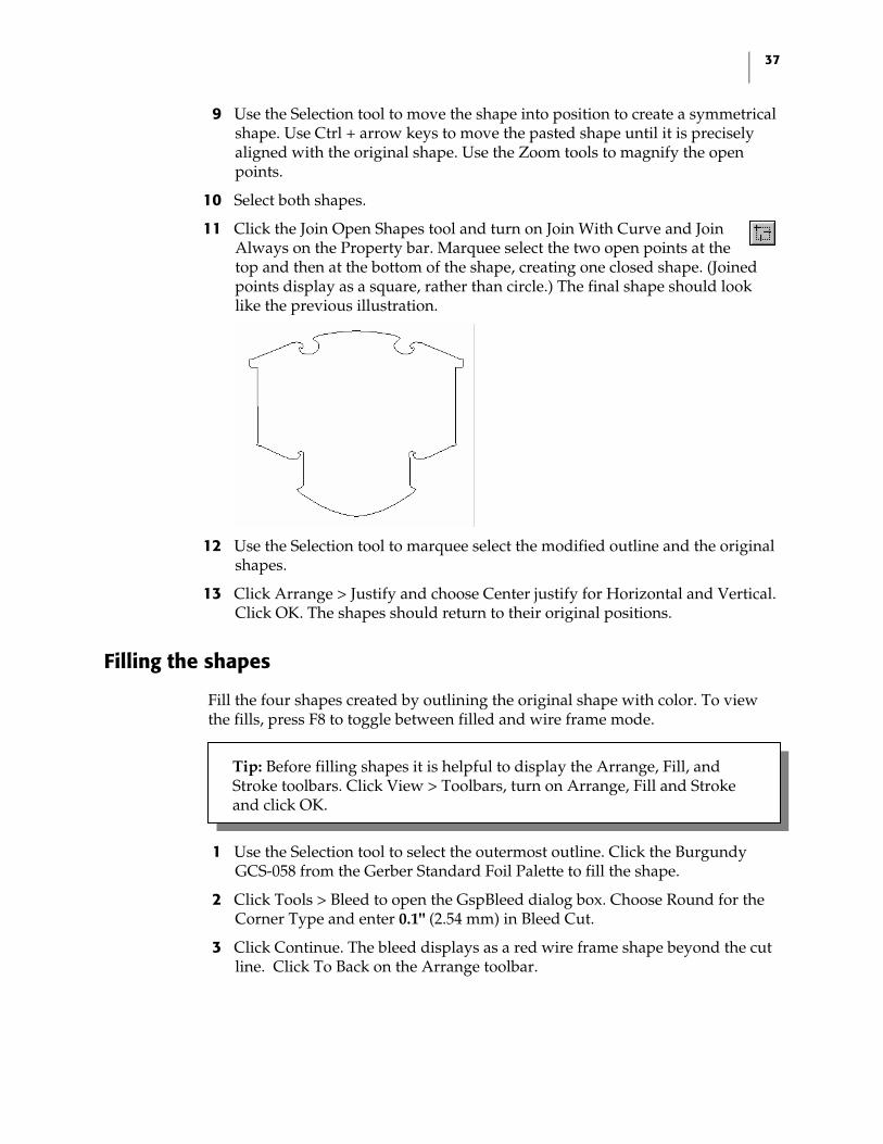
11 Click the Join Open Shapes tool and turn on Join With Curve and Join Always on the Property bar. Marquee select the two open points at the top and then at the bottom of the shape, creating one closed shape. (Joined points display as a square, rather than circle.) The final shape should look like the previous illustration.
12 Use the Selection tool to marquee select the modified outline and the original shapes.
13 Click Arrange > Justify and choose Center justify for Horizontal and Vertical. Click OK. The shapes should return to their original positions.
Filling the shapes
Fill the four shapes created by outlining the original shape with color. To view the fills, press F8 to toggle between filled and wire frame mode.
1 Use the Selection tool to select the outermost outline. Click the Burgundy GCS-058 from the Gerber Standard Foil Palette to fill the shape.
2 Click Tools > Bleed to open the GspBleed dialog box. Choose Round for the Corner Type and enter 0.1" (2.54 mm) in Bleed Cut.
3 Click Continue. The bleed displays as a red wire frame shape beyond the cut line. Click To Back on the Arrange toolbar.
Tip: Before filling shapes it is helpful to display the Arrange, Fill, and Stroke toolbars. Click View > Toolbars, turn on Arrange, Fill and Stroke and click OK.
38 Solutions Final Exam
4 Use the Selection tool to select the next outline inside the Burgundy shape. (Not the Burgundy shape’s cut line.) Click Black GCS-012 in the Gerber Standard Foil Palette to fill the shape.
5 Click Cuts Off on the Arrange toolbar to remove the cut line. Click To Front on the Arrange toolbar.
6 Use the Selection tool to select the next outline inside the black shape. Click Process Cyan in the Gerber Process Colors Palette to fill the shape.
7 Click Cuts Off on the Arrange toolbar to remove the cut line, then click To Front.
8 Use the Selection tool to select the innermost outline.
9 Click Fill to open the Assign Colors dialog box to create a linear fill. Enter the following settings: ♦ Turn on Linear to activate the Linear controls. ♦ Enter 90 in Linear Angle. ♦ Turn on Process in Color Type.
10 In the Color box, click the color sample button to open the Color Name box. Choose Black and click Select. The linear fill should be Black fading to Process Cyan in the color sample box.
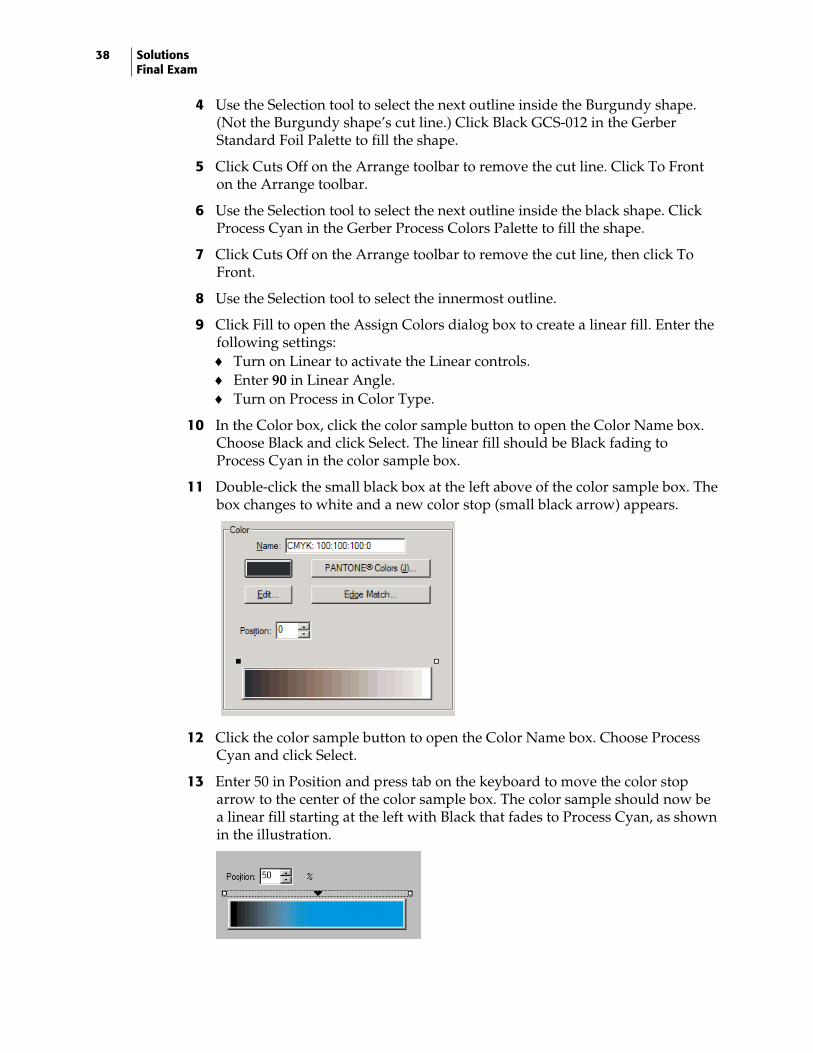
11 Double-click the small black box at the left above of the color sample box. The box changes to white and a new color stop (small black arrow) appears.
12 Click the color sample button to open the Color Name box. Choose Process Cyan and click Select.
13 Enter 50 in Position and press tab on the keyboard to move the color stop arrow to the center of the color sample box. The color sample should now be a linear fill starting at the left with Black that fades to Process Cyan, as shown in the illustration.
39
14 Double-click the small white box to the right above the color sample box. Another color stop arrow appears.
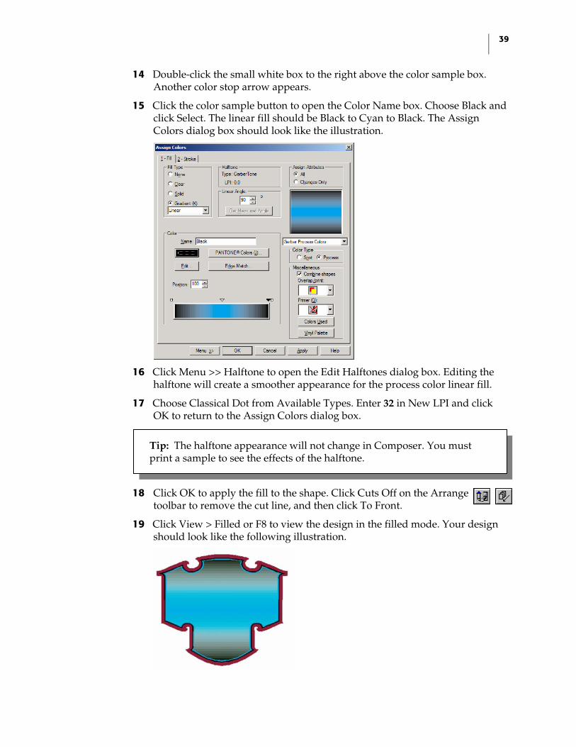
15 Click the color sample button to open the Color Name box. Choose Black and click Select. The linear fill should be Black to Cyan to Black. The Assign Colors dialog box should look like the illustration.
16 Click Menu >> Halftone to open the Edit Halftones dialog box. Editing the halftone will create a smoother appearance for the process color linear fill.
17 Choose Classical Dot from Available Types. Enter 32 in New LPI and click OK to return to the Assign Colors dialog box.
18 Click OK to apply the fill to the shape. Click Cuts Off on the Arrange toolbar to remove the cut line, and then click To Front.
19 Click View > Filled or F8 to view the design in the filled mode. Your design should look like the following illustration.
Tip: The halftone appearance will not change in Composer. You must print a sample to see the effects of the halftone.

40 Solutions Final Exam
20 Marquee select all of the outlines and click Arrange > Group to group the shapes into a single unit.
Ensuring Print-to-Print registration
Quick instructions
Apply Choke/Spread to the outlines to ensure that they register correctly without a gap between the filled shapes. Apply a Choke/Spread to the Black and Burgundy shape and then to the Black and Cyan shape using the following settings: Black is the top color, Points is the corner type and 0.025" (0.635 mm) is the amount.
Detailed instructions
1 Select the Black filled outline and then the Burgundy filled outline using the Selection tool and the Shift key.
2 Click Tools > Choke/Spread to open the Choke/Spread dialog box. Enter the following settings: ♦ Choose Black as the Top Color. ♦ Choose Points in Corner. ♦ Enter 0.025" (0.635 mm) in Choke/Spread Amount.
3 Click Continue to apply the Choke/Spread. You will notice a new line representing the edge of the Burgundy fill 0.025" (0.635 mm) inside the Black Outline.
4 Select the Black filled outline and then the Cyan filled outline using the Selection tool and the Shift key.
5 Click Tools > Choke/Spread to open the Choke/Spread dialog box. Enter the following settings: ♦ Choose Black as the Top Color. ♦ Choose Points in Corner. ♦ Enter 0.025" (0.635 mm) in Choke/Spread Amount.
6 Click Continue to apply the Choke/Spread. You will notice a new line representing the edge of the Cyan fill 0.025" (0.635 mm) inside the Black Outline.
7 Click File > Save to save your design.
41
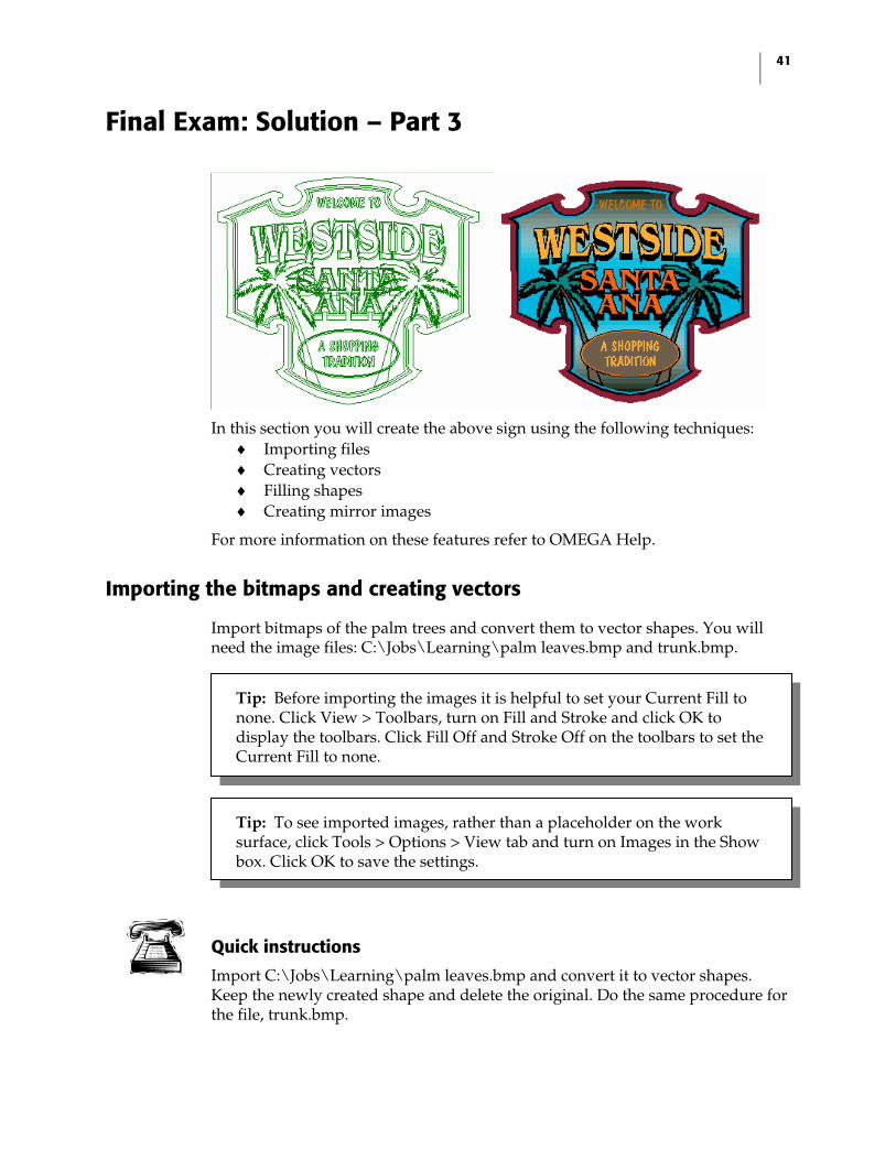
Final Exam: Solution – Part 3
In this section you will create the above sign using the following techniques:
♦ Importing files ♦ Creating vectors ♦ Filling shapes ♦ Creating mirror images
For more information on these features refer to OMEGA Help.
Importing the bitmaps and creating vectors
Import bitmaps of the palm trees and convert them to vector shapes. You will need the image files: C:\Jobs\Learning\palm leaves.bmp and trunk.bmp.
Quick instructions
Import C:\Jobs\Learning\palm leaves.bmp and convert it to vector shapes. Keep the newly created shape and delete the original. Do the same procedure for the file, trunk.bmp.
Tip: Before importing the images it is helpful to set your Current Fill to none. Click View > Toolbars, turn on Fill and Stroke and click OK to display the toolbars. Click Fill Off and Stroke Off on the toolbars to set the Current Fill to none.
Tip: To see imported images, rather than a placeholder on the work surface, click Tools > Options > View tab and turn on Images in the Show box. Click OK to save the settings.
42 Solutions Final Exam
Detailed instructions
1 Click File > Import to open the Import dialog box. In Files of type choose BMP – Microsoft Windows Bitmap.
2 Navigate to C:\Jobs\Learning\palm leaves.bmp.
3 Clear the Keep Layers checkbox.
4 Turn on Current Layer.
5 Click Import. The image appears selected on the work surface.
6 Click Tools > Raster to Vector. Accept the default settings of 3 in Speck Size and Low Resolution and click OK.
7 Move the newly created vector shape to an empty area on the work surface. Select the remaining imported image and delete it.
8 Repeat the import and Raster to Vector conversion procedure with the file C:\Jobs\Learning\trunk.bmp.
Filling the vector shapes
In this section you will fill the vector shapes and give them a stroke. To view the fills, press F8 to toggle between filled and wire frame mode.
1 Use the Selection tool to select the tree trunk and click Fill to open the Assign Colors dialog box.
2 Click the Fill tab and turn on Solid to activate the solid fill controls. Enter the following settings: ♦ Turn on Spot in Color Type ♦ Choose Brown GCS-019
3 Click the Stroke tab and turn on Solid to activate the Stroke controls. Enter the following Stroke Attributes: ♦ Enter 0.023" (0.584 mm) in Width. ♦ Choose Round End Type. ♦ Choose Round Join Type. ♦ In Selected Color, choose Black GCS-012. ♦ Turn on Overlap in Print Attributes.
4 Click OK to apply fill and stroke to the trunk. Click Cuts Off on the Arrange toolbar to remove cut lines.
Tip: Before filling the images it is helpful to set your Current Fill to none. Click View > Toolbars, turn on Fill and Stroke and click OK to display the toolbars. Click Fill Off and Stroke Off on the toolbars to set the Current Fill to none.
43
5 Use the Selection tool to marquee select the palm leaves and click Fill to open the Assign Colors dialog box.
6 Click the Fill tab and turn on Solid to activate the solid fill controls. Turn on Process in Color Type.
7 Click the Edit button in the Color box to open the Color Edit dialog box. Enter the following color code: C100, M0, Y58, and K60. Turn on Auto Update Name (to have the color name reflect the changes) and click OK.
8 Click the Stroke tab and turn on Solid to activate the Stroke controls. Enter the following Stroke Attributes: ♦ Enter 0.023" (0.584 mm) in Width. ♦ Choose Round End Type. ♦ Choose Round Join Type. ♦ In Selected Color, choose Black GCS-012. ♦ Turn on Overlap in Print Attributes.
9 Click OK to apply fill and stroke to the palm leaves. Click Cuts Off on the Arrange toolbar to remove the cut lines.
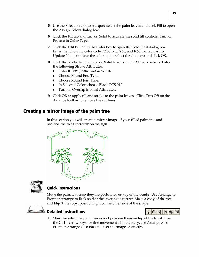
Creating a mirror image of the palm tree
In this section you will create a mirror image of your filled palm tree and position the trees correctly on the sign.
Quick instructions
Move the palm leaves so they are positioned on top of the trunks. Use Arrange to Front or Arrange to Back so that the layering is correct. Make a copy of the tree and Flip X the copy, positioning it on the other side of the shape.
Detailed instructions
1 Marquee select the palm leaves and position them on top of the trunk. Use the Ctrl + arrow keys for fine movements. If necessary, use Arrange > To Front or Arrange > To Back to layer the images correctly.
44 Solutions Final Exam
2 Marquee select the leaves and the trunk and click Arrange > Group to turn the two objects into a single unit.
3 Click Edit > Copy and then Edit > Paste to create a copy of the palm tree. The pasted object appears selected on the work surface.
4 Click Shape > Flip X and click the work surface to set the location of the flipped copy.
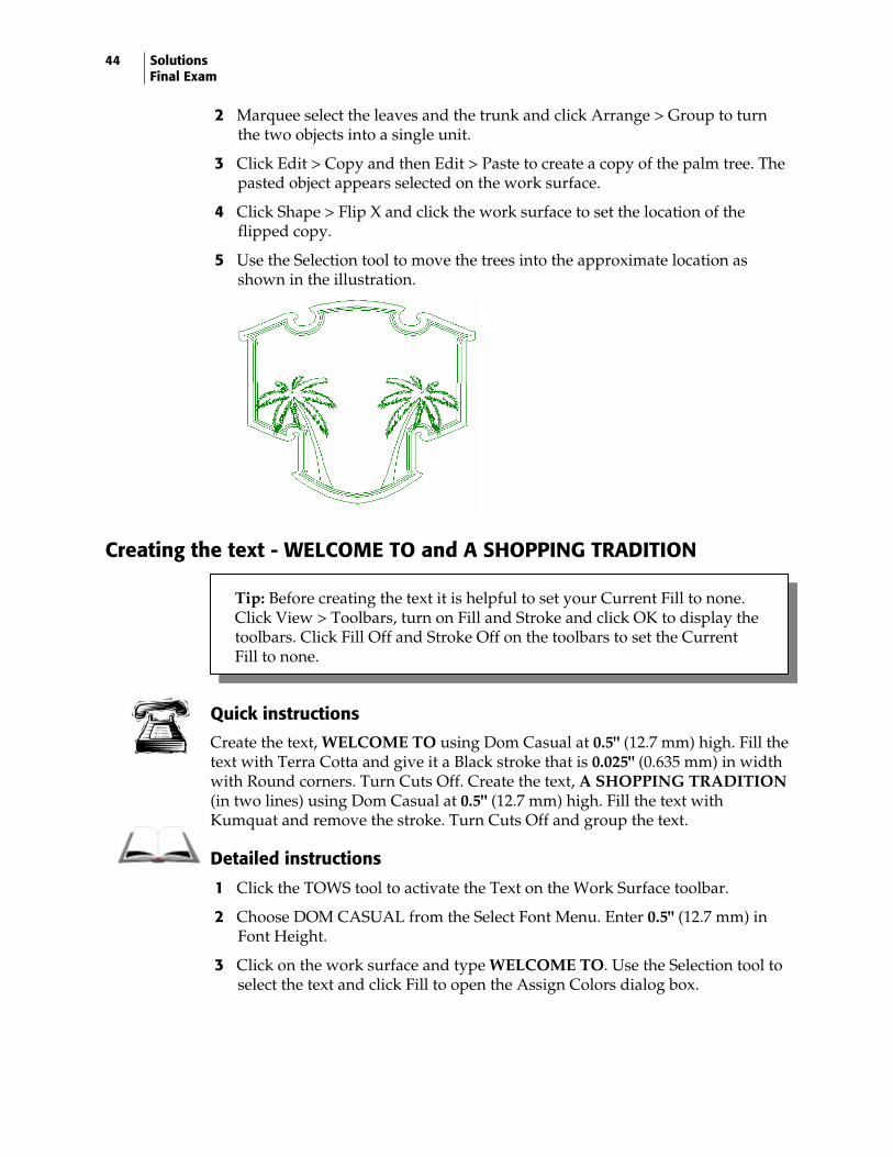
5 Use the Selection tool to move the trees into the approximate location as shown in the illustration.
Creating the text - WELCOME TO and A SHOPPING TRADITION
Quick instructions
Create the text, WELCOME TO using Dom Casual at 0.5" (12.7 mm) high. Fill the text with Terra Cotta and give it a Black stroke that is 0.025" (0.635 mm) in width with Round corners. Turn Cuts Off. Create the text, A SHOPPING TRADITION (in two lines) using Dom Casual at 0.5" (12.7 mm) high. Fill the text with Kumquat and remove the stroke. Turn Cuts Off and group the text.
Detailed instructions
1 Click the TOWS tool to activate the Text on the Work Surface toolbar.
2 Choose DOM CASUAL from the Select Font Menu. Enter 0.5" (12.7 mm) in Font Height.
3 Click on the work surface and type WELCOME TO. Use the Selection tool to select the text and click Fill to open the Assign Colors dialog box.
Tip: Before creating the text it is helpful to set your Current Fill to none. Click View > Toolbars, turn on Fill and Stroke and click OK to display the toolbars. Click Fill Off and Stroke Off on the toolbars to set the Current Fill to none.
45
4 On the Fill tab and choose Solid to activate the Fill controls. Enter the following Fill Attributes: ♦ Turn on Spot in Color Type. ♦ In Selected Color choose Terra Cotta GCS-024.
5 Click the Stroke tab and choose Solid to activate the Stroke controls. Enter the following Stroke Attributes: ♦ Enter 0.025" (0.635 mm) in Width. ♦ Choose Round End Type. ♦ Choose Round Join Type. ♦ In Selected Color, choose Black GCS-012.
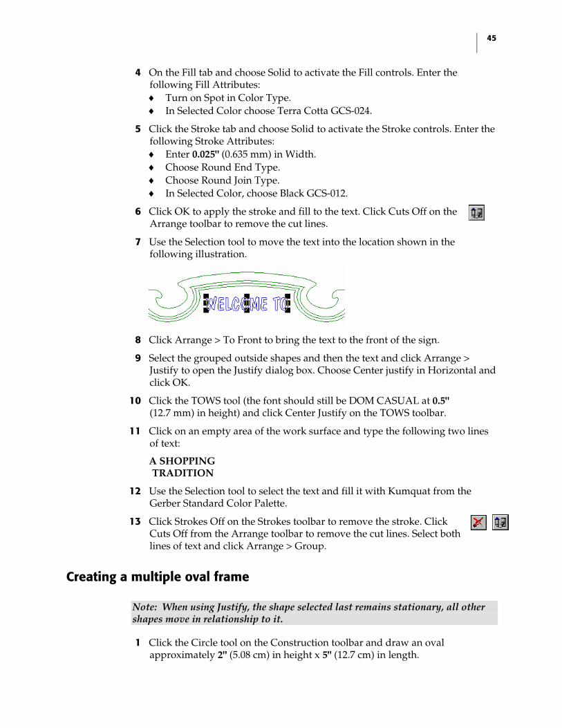
6 Click OK to apply the stroke and fill to the text. Click Cuts Off on the Arrange toolbar to remove the cut lines.
7 Use the Selection tool to move the text into the location shown in the following illustration.
8 Click Arrange > To Front to bring the text to the front of the sign.
9 Select the grouped outside shapes and then the text and click Arrange > Justify to open the Justify dialog box. Choose Center justify in Horizontal and click OK.
10 Click the TOWS tool (the font should still be DOM CASUAL at 0.5" (12.7 mm) in height) and click Center Justify on the TOWS toolbar.
11 Click on an empty area of the work surface and type the following two lines of text:
A SHOPPING TRADITION
12 Use the Selection tool to select the text and fill it with Kumquat from the Gerber Standard Color Palette.
13 Click Strokes Off on the Strokes toolbar to remove the stroke. Click Cuts Off from the Arrange toolbar to remove the cut lines. Select both lines of text and click Arrange > Group.
Creating a multiple oval frame
Note: When using Justify, the shape selected last remains stationary, all other shapes move in relationship to it.
1 Click the Circle tool on the Construction toolbar and draw an oval approximately 2" (5.08 cm) in height x 5" (12.7 cm) in length.
46 Solutions Final Exam
2 Click Shape > Absolute Size to open the Absolute Size dialog box. Enter the following settings: ♦ Turn on Non-Uniform. ♦ Enter 2.2" (5.58 cm) in Height. ♦ Enter 4.8" (12.19 cm) in Length.
3 Click OK to change the size of the oval.
4 Select the oval and click Tools > Outline to open the Outline dialog box. In Pass 1 enter the following settings: ♦ Turn on Round. ♦ Enter 2 in Number of Outlines. ♦ Enter 0.05" (1.27 mm) in Outline Distance.
5 Click OK to apply the outlines to the oval.
6 Click the outermost oval and fill it with Black from the Gerber Standard Color Palette.
7 Click the middle outline and fill it with Orange from the Gerber Standard Color Palette.
8 Click the inner shape and fill it with Brown from the Gerber Standard Color Palette.
9 Marquee select all the outlines and click Cuts Off on the Arrange toolbar to remove the cut lines.
10 With the outlines still selected, select the grouped text A SHOPPING TRADITION.
11 Click Arrange > Justify to open the Justify dialog box. Click Center justify for both Horizontal and Vertical and then click OK.
Note: If your lines of text are on top of each other, you did not group the text first. Click Edit > Undo and group the text using Arrange > Group, then justify the text and outlines.
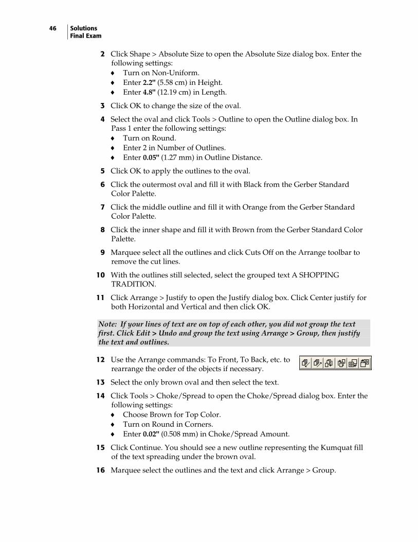
12 Use the Arrange commands: To Front, To Back, etc. to rearrange the order of the objects if necessary.
13 Select the only brown oval and then select the text.
14 Click Tools > Choke/Spread to open the Choke/Spread dialog box. Enter the following settings: ♦ Choose Brown for Top Color. ♦ Turn on Round in Corners. ♦ Enter 0.02" (0.508 mm) in Choke/Spread Amount.
15 Click Continue. You should see a new outline representing the Kumquat fill of the text spreading under the brown oval.
16 Marquee select the outlines and the text and click Arrange > Group.
47
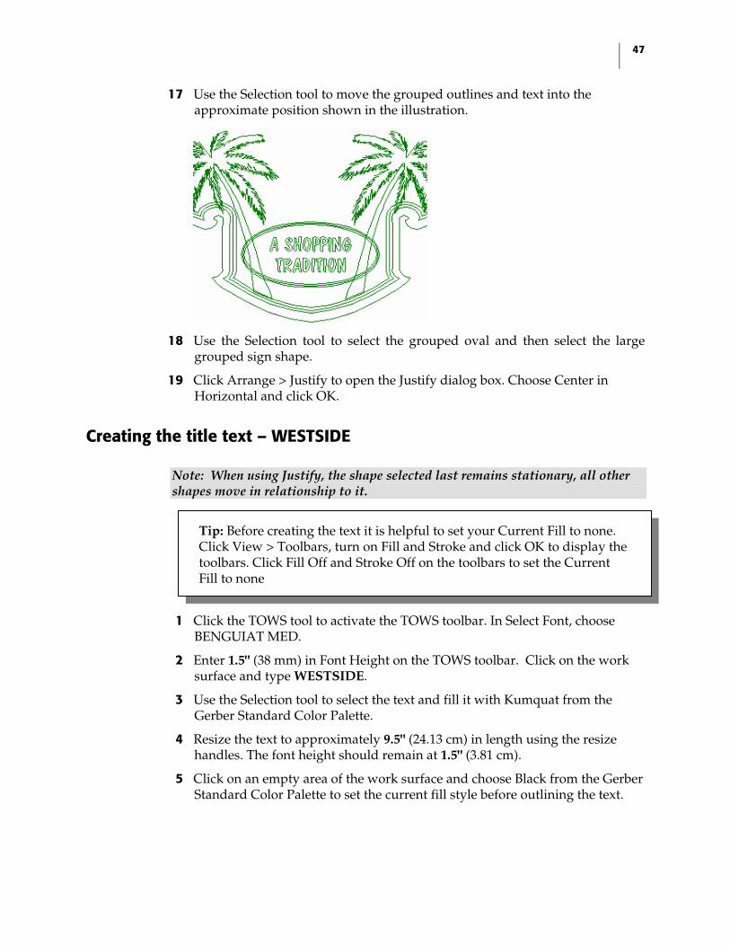
17 Use the Selection tool to move the grouped outlines and text into the approximate position shown in the illustration.
18 Use the Selection tool to select the grouped oval and then select the large grouped sign shape.
19 Click Arrange > Justify to open the Justify dialog box. Choose Center in Horizontal and click OK.
Creating the title text – WESTSIDE
Note: When using Justify, the shape selected last remains stationary, all other shapes move in relationship to it.
1 Click the TOWS tool to activate the TOWS toolbar. In Select Font, choose BENGUIAT MED.
2 Enter 1.5" (38 mm) in Font Height on the TOWS toolbar. Click on the work surface and type WESTSIDE.
3 Use the Selection tool to select the text and fill it with Kumquat from the Gerber Standard Color Palette.
4 Resize the text to approximately 9.5" (24.13 cm) in length using the resize handles. The font height should remain at 1.5" (3.81 cm).
5 Click on an empty area of the work surface and choose Black from the Gerber Standard Color Palette to set the current fill style before outlining the text.
Tip: Before creating the text it is helpful to set your Current Fill to none. Click View > Toolbars, turn on Fill and Stroke and click OK to display the toolbars. Click Fill Off and Stroke Off on the toolbars to set the Current Fill to none
48 Solutions Final Exam
6 Use the Selection tool to select the text. Click Tools > Outline to open the Outline dialog box. Enter the following settings in Pass 1: ♦ Choose Points in Corner Types. ♦ Enter 1 in Number of Outlines. ♦ Enter 0.050" (1.27mm) in Distance.
7 Click OK to apply the outline to the text.
8 Marquee select the text and click Tools > Choke Spread to open the Choke Spread dialog box. Enter the following settings: ♦ Choose Black as Top Color. ♦ Choose Points in Corners. ♦ Enter 0.025" (0.635 mm) in Choke/Spread Amount.
9 Click Continue to apply the Choke/Spread. Select only the outer outline of the text. Do not select the inner outline shape or the Choke/Spread line.
10 Click Tools > Shadow to open the Shadow dialog box. Enter the following settings: ♦ Choose Shade as the Type. ♦ Enter 0.3" (7.62 mm) in Depth. ♦ Enter –90.0 in Angle. ♦ Choose Partial.
11 Click Continue to apply the shadow to the text. Click Tools > Distortion to open the Distortion dialog box. Choose 42 Vertical Arc Up and click Continue to open the Modify Parameters dialog box.
12 Enter in 0.3" (7.62 mm) in H2 and click OK to apply the distortion to the text. Marquee select the text and click Cuts Off on the Arrange toolbar to remove the cut lines.
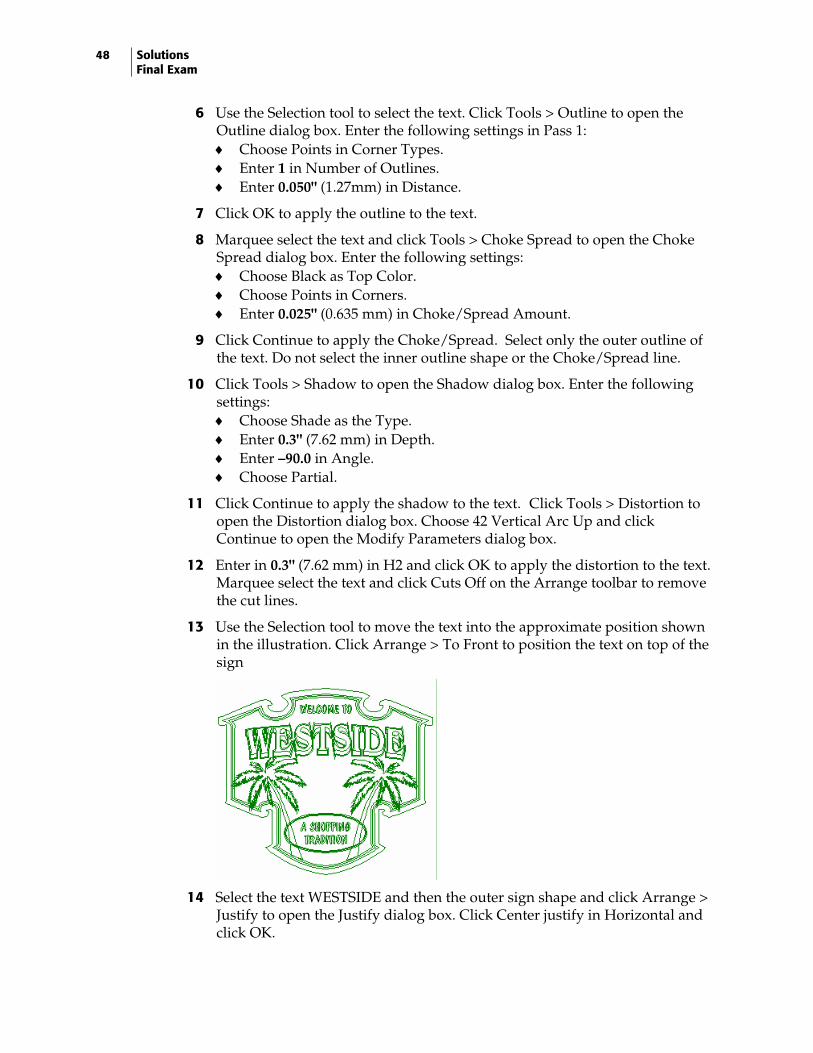
13 Use the Selection tool to move the text into the approximate position shown in the illustration. Click Arrange > To Front to position the text on top of the sign
14 Select the text WESTSIDE and then the outer sign shape and click Arrange > Justify to open the Justify dialog box. Click Center justify in Horizontal and click OK.
49
Creating the subtitle text - SANTA ANA
1 Click the TOWS tool and choose BENGUIAT MED if it is not the active font.
2 Enter 1.0" (2.54 cm) in Font Height and click Center Justify on the TOWS toolbar.
3 Click on an empty area of the work surface and type following text in two lines:
SANTA ANA
4 Put the TOWS cursor in the word ANA and enter 1.2 in Line Spacing on the TOWS toolbar. The second line of text should move closer to the first line.
5 Use the Selection tool to select the text and fill it with Orange from the Gerber Standard Color Palette.
6 Click on an empty area of the work surface and click Black from the Gerber Standard Color Palette to set the Current Style before outlining the text.
7 Use the Selection tool to select the text SANTA ANA.
8 Click Tools > Outline to open the Outline dialog box. Enter the following settings in Pass 1: ♦ Choose Points in Corner Types. ♦ Enter 1 in Number of Outlines. ♦ Enter 0.050" (1.27 mm) in Distance.
9 Click OK to apply the outline to the text. Select only outer outline of the text.
10 Click Tools > Shadow to open the Shadow dialog box. Enter the following settings: ♦ Choose Shade as the Type. ♦ Enter 0.300" (7.62 mm) in Depth. ♦ Enter –90.0 in Angle. ♦ Choose Partial.
11 Click Continue to apply the shadow to the text.
12 Marquee select both lines of text and click Cuts Off on the Arrange toolbar to remove the cut lines. With the text still selected, click Arrange > Group.
13 Use the Selection tool to move the grouped text into the approximate position.
Tip: Before creating the text it is helpful to set your Current Fill to none. Click View > Toolbars, turn on Fill and Stroke and click OK to display the toolbars. Click Fill Off and Stroke Off on the toolbars to set the Current Fill to none
50 Solutions Final Exam
14 Click Arrange > To Front to position the text on top of the palm trees. Select the grouped text SANTA ANA and then select the outside sign shape.
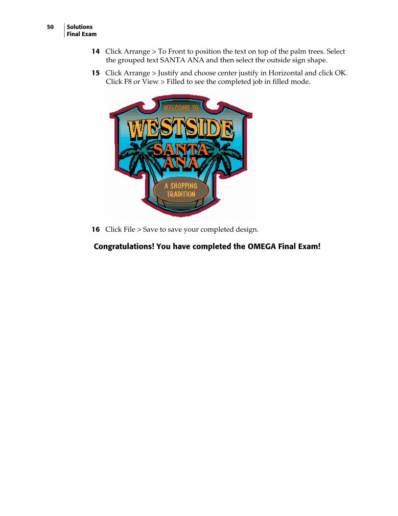
15 Click Arrange > Justify and choose center justify in Horizontal and click OK. Click F8 or View > Filled to see the completed job in filled mode.
16 Click File > Save to save your completed design.
Congratulations! You have completed the OMEGA Final Exam!