Embed Size (px)
Citation preview
SolidWorks 98Plus
What’s New
SolidWorks Corporation150 Baker Avenue Ext.Concord, Massachusetts 01742

© 1998, SolidWorks Corporation Concord, Massachusetts 01742All Rights Reserved.
SolidWorks Corporation is a Dassault Systemes S.A. (Nasdaq:DASTY) company. Information is subject to change without notice. No material may be reproduced or transmitted in any form or by any means, electronic or mechanical, for any purpose without the express written permission of SolidWorks Corporation.As a condition to your use of this software product, you agree to accept the limited warranty, disclaimer and other terms and conditions set forth in the SolidWorks Corporation License Agreement which accompanies this software. If, after reading the License Agreement, you do not agree with the limited warranty, the disclaimer or any of the other terms and conditions, promptly return the unused software and all accompanying documentation to SolidWorks Corporation and your money will be refunded.SolidWorks® is a registered trademark of SolidWorks Corporation.SolidWorks® 98Plus is a product name of SolidWorks Corporation.
FeatureManager™, Feature Palette™, and PhotoWorks™ are trademarks of SolidWorks Corporation. ACIS® is a registered trademark of Spatial Technology Inc.IGES™ Access Library is a trademark of IGES Data Analysis, Inc. FeatureWorks™ is a trademark of Geometric Software Services Co. Limited. Other brand or product names are trademarks or registered trademarks of their respective holders.All warranties given by SolidWorks Corporation as to the software and documentation are set forth in the End-User License and Subscription Service Agreement, and nothing stated in, or implied by, this document or its contents shall be considered or deemed a modification or amendment of such warranties. The information and the software discussed in this document are subject to change without notice and should not be considered commitments by SolidWorks Corporation.
Document Number: SWXWNENG-100098
The software discussed in this document is furnished under a license and may be used or copied only in accordance with the terms of this license.COMMERCIAL COMPUTER SOFTWARE - PROPRIETARYThis computer software is Commercial Computer Software, as defined in subparagraph (a) (1) of DFAR section 252.227.7014, “Rights in Noncommercial Computer Software and Noncommercial Computer Software Documentation.” Use, duplication or disclosure by the Government is subject to restrictions as set forth in the SolidWorks Corporation License Agreement accompanying this computer software.Portions of this software are copyrighted by and are the property of Unigraphics Solutions Inc. Portions of this software © 1995 - 1998 D-Cubed Limited.Portions of this software © 1992-1998Summit Software Company.Portions of this software © 1990-1998 LightWork Design Limited.Portions of this software © 1995-1998 Spatial Technology Inc.Portions of this software © 1998 Geometric Software Services Co. Limited.The IGES Access Library portion of this product is based on IDA IGES Access Library © 1989-1998 IGES Data Analysis, Inc. All Rights Reserved.
U.S. Patent 5,815,154
What’s New in SolidWorks 98Plus
-2 1-2
2-1 2-1 2-1. 2-12-1
2-1 2-2 2-3 2-4 2-5 2-52-6. 2-6 2-6 2-62-6. 2-7. 2-72-7 2-8 2-8
Table of Contents
IntroductionAbout this Book . . . . . . . . . . . . . . . . . . . . . . . . . . . . . . . . . . . . . . . 1-1
Using this Book . . . . . . . . . . . . . . . . . . . . . . . . . . . . . . . . . . . . 1-1A Word About Files . . . . . . . . . . . . . . . . . . . . . . . . . . . . . . . . . 1-1Format of this Manual . . . . . . . . . . . . . . . . . . . . . . . . . . . . . . . 1-1Conventions Used in this Book . . . . . . . . . . . . . . . . . . . . . . . . 1-2WindowsNT™ 4.0 . . . . . . . . . . . . . . . . . . . . . . . . . . . . . . . . . . 1Last Minute Changes . . . . . . . . . . . . . . . . . . . . . . . . . . . . . . . .
General InformationIntroduction . . . . . . . . . . . . . . . . . . . . . . . . . . . . . . . . . . . . . . . . . .Options Dialog . . . . . . . . . . . . . . . . . . . . . . . . . . . . . . . . . . . . . . . .
General Tab . . . . . . . . . . . . . . . . . . . . . . . . . . . . . . . . . . . . . . .Edges Tab. . . . . . . . . . . . . . . . . . . . . . . . . . . . . . . . . . . . . . . . Detailing Tab . . . . . . . . . . . . . . . . . . . . . . . . . . . . . . . . . . . . . . Line Font Tab. . . . . . . . . . . . . . . . . . . . . . . . . . . . . . . . . . . . . .Performance Tab . . . . . . . . . . . . . . . . . . . . . . . . . . . . . . . . . . .Drawings Tab . . . . . . . . . . . . . . . . . . . . . . . . . . . . . . . . . . . . . .External References Tab . . . . . . . . . . . . . . . . . . . . . . . . . . . . .Export Tab . . . . . . . . . . . . . . . . . . . . . . . . . . . . . . . . . . . . . . . .Import Tab . . . . . . . . . . . . . . . . . . . . . . . . . . . . . . . . . . . . . . . .
Highlighting . . . . . . . . . . . . . . . . . . . . . . . . . . . . . . . . . . . . . . . . . . FeatureManager Design Tree . . . . . . . . . . . . . . . . . . . . . . . . . . . .
Go To Text Search . . . . . . . . . . . . . . . . . . . . . . . . . . . . . . . . . .Go To Feature — Graphic Search . . . . . . . . . . . . . . . . . . . . . .Window Size . . . . . . . . . . . . . . . . . . . . . . . . . . . . . . . . . . . . . . Feature Names . . . . . . . . . . . . . . . . . . . . . . . . . . . . . . . . . . . .
Perspective Views. . . . . . . . . . . . . . . . . . . . . . . . . . . . . . . . . . . . . Multi-selection . . . . . . . . . . . . . . . . . . . . . . . . . . . . . . . . . . . . . . . . Offset Text . . . . . . . . . . . . . . . . . . . . . . . . . . . . . . . . . . . . . . . . . . .Dimension Units. . . . . . . . . . . . . . . . . . . . . . . . . . . . . . . . . . . . . . .
i
What’s New in SolidWorks 98Plus
2-172-18-18-192-19
2-19-20-20-20-20
2-20-20-202-21
2-21
. 3-1
. 3-13-23-2
. 3-3 3-33-4
. 3-5 3-9 3-9
Reference Dimensions . . . . . . . . . . . . . . . . . . . . . . . . . . . . . . . . . . 2-9Toolbars . . . . . . . . . . . . . . . . . . . . . . . . . . . . . . . . . . . . . . . . . . . . . 2-9
Dependency Editing. . . . . . . . . . . . . . . . . . . . . . . . . . . . . . . . . 2-9Features . . . . . . . . . . . . . . . . . . . . . . . . . . . . . . . . . . . . . . . . . . 2-9View Orientation Dialog . . . . . . . . . . . . . . . . . . . . . . . . . . . . 2-10View Toolbar . . . . . . . . . . . . . . . . . . . . . . . . . . . . . . . . . . . . . 2-10Standard Views . . . . . . . . . . . . . . . . . . . . . . . . . . . . . . . . . . . 2-10Selection Filter Toolbar . . . . . . . . . . . . . . . . . . . . . . . . . . . . . 2-11Keyboard Shortcuts . . . . . . . . . . . . . . . . . . . . . . . . . . . . . . . . 2-12
Collapse Items . . . . . . . . . . . . . . . . . . . . . . . . . . . . . . . . . . . . . . . 2-12Coordinate Systems . . . . . . . . . . . . . . . . . . . . . . . . . . . . . . . . . . . 2-12
Creating Coordinate Systems. . . . . . . . . . . . . . . . . . . . . . . . . 2-12Using the Coordinate System. . . . . . . . . . . . . . . . . . . . . . . . . 2-13
Measurement Options. . . . . . . . . . . . . . . . . . . . . . . . . . . . . . . . . . 2-16Reference Axis . . . . . . . . . . . . . . . . . . . . . . . . . . . . . . . . . . . . . . . 2-16Feature Palette™ Window . . . . . . . . . . . . . . . . . . . . . . . . . . . . . .
Using the Palette . . . . . . . . . . . . . . . . . . . . . . . . . . . . . . . . . . Adding to the Palette . . . . . . . . . . . . . . . . . . . . . . . . . . . . . . . 2Edit Palette Item. . . . . . . . . . . . . . . . . . . . . . . . . . . . . . . . . . . 2Palette Feature Names in the FeatureManager . . . . . . . . . . .
Object Snap Changes . . . . . . . . . . . . . . . . . . . . . . . . . . . . . . . . . .Drag and Drop from Internet Explorer. . . . . . . . . . . . . . . . . . . . . 2Importing and Exporting Data . . . . . . . . . . . . . . . . . . . . . . . . . . . 2
IGES. . . . . . . . . . . . . . . . . . . . . . . . . . . . . . . . . . . . . . . . . . . . 2SAT . . . . . . . . . . . . . . . . . . . . . . . . . . . . . . . . . . . . . . . . . . . . 2STEP . . . . . . . . . . . . . . . . . . . . . . . . . . . . . . . . . . . . . . . . . . . Parasolids (X_T and X_B). . . . . . . . . . . . . . . . . . . . . . . . . . . 2VDA. . . . . . . . . . . . . . . . . . . . . . . . . . . . . . . . . . . . . . . . . . . . 2
Service Packs . . . . . . . . . . . . . . . . . . . . . . . . . . . . . . . . . . . . . . . . Converting Files . . . . . . . . . . . . . . . . . . . . . . . . . . . . . . . . . . . . . .
Modeling EnhancementsSketching . . . . . . . . . . . . . . . . . . . . . . . . . . . . . . . . . . . . . . . . . . .
Parabola . . . . . . . . . . . . . . . . . . . . . . . . . . . . . . . . . . . . . . . . . Simplify Spline . . . . . . . . . . . . . . . . . . . . . . . . . . . . . . . . . . . . Add Geometric Relations. . . . . . . . . . . . . . . . . . . . . . . . . . . . . Revolved Features . . . . . . . . . . . . . . . . . . . . . . . . . . . . . . . . .
Lofting . . . . . . . . . . . . . . . . . . . . . . . . . . . . . . . . . . . . . . . . . . . . . .Lofting Between Surfaces . . . . . . . . . . . . . . . . . . . . . . . . . . . .
Shape Feature . . . . . . . . . . . . . . . . . . . . . . . . . . . . . . . . . . . . . . . .Working with Surfaces . . . . . . . . . . . . . . . . . . . . . . . . . . . . . . . . . .
Surfaces Behavior . . . . . . . . . . . . . . . . . . . . . . . . . . . . . . . . . .
ii
What’s New in SolidWorks 98Plus
Planar Surface . . . . . . . . . . . . . . . . . . . . . . . . . . . . . . . . . . . . . 3-9Radiate Surface . . . . . . . . . . . . . . . . . . . . . . . . . . . . . . . . . . . 3-10Knit Surface . . . . . . . . . . . . . . . . . . . . . . . . . . . . . . . . . . . . . . 3-10Example . . . . . . . . . . . . . . . . . . . . . . . . . . . . . . . . . . . . . . . . . 3-11Another Knit Example . . . . . . . . . . . . . . . . . . . . . . . . . . . . . . 3-14
Parting Line Draft. . . . . . . . . . . . . . . . . . . . . . . . . . . . . . . . . . . . . 3-16Step Draft . . . . . . . . . . . . . . . . . . . . . . . . . . . . . . . . . . . . . . . . 3-16
Working with Curves . . . . . . . . . . . . . . . . . . . . . . . . . . . . . . . . . . 3-17Reference Curves . . . . . . . . . . . . . . . . . . . . . . . . . . . . . . . . . . 3-17Composite Curves . . . . . . . . . . . . . . . . . . . . . . . . . . . . . . . . . 3-17
Cosmetic Threads . . . . . . . . . . . . . . . . . . . . . . . . . . . . . . . . . . . . . 3-17Patterns . . . . . . . . . . . . . . . . . . . . . . . . . . . . . . . . . . . . . . . . . . . . . 3-18Sheet Metal . . . . . . . . . . . . . . . . . . . . . . . . . . . . . . . . . . . . . . . . . . 3-18
Unroll Sheet Metal . . . . . . . . . . . . . . . . . . . . . . . . . . . . . . . . . 3-18Design Guidelines . . . . . . . . . . . . . . . . . . . . . . . . . . . . . . . . . 3-19Developments of Intersecting Cylinders . . . . . . . . . . . . . . . . 3-21Form features . . . . . . . . . . . . . . . . . . . . . . . . . . . . . . . . . . . . . 3-23Creating Your Own Forming Tools . . . . . . . . . . . . . . . . . . . . 3-28
Configurations . . . . . . . . . . . . . . . . . . . . . . . . . . . . . . . . . . . . . . . 3-30Library Features . . . . . . . . . . . . . . . . . . . . . . . . . . . . . . . . . . . . . . 3-31
Edit Dimension Access . . . . . . . . . . . . . . . . . . . . . . . . . . . . . 3-31Simplification of Library Features. . . . . . . . . . . . . . . . . . . . . 3-37
Design Tables . . . . . . . . . . . . . . . . . . . . . . . . . . . . . . . . . . . . . . . . 3-38
Drawing EnhancementsImporting Model Dimensions. . . . . . . . . . . . . . . . . . . . . . . . . . . . . 4-1Detail and Section Views . . . . . . . . . . . . . . . . . . . . . . . . . . . . . . . . 4-1Auto Hatching of Section Views . . . . . . . . . . . . . . . . . . . . . . . . . . 4-1Multiple Leaders. . . . . . . . . . . . . . . . . . . . . . . . . . . . . . . . . . . . . . . 4-2Dynamic View Activation . . . . . . . . . . . . . . . . . . . . . . . . . . . . . . . 4-2
Lock Sheet Focus. . . . . . . . . . . . . . . . . . . . . . . . . . . . . . . . . . . 4-3Lock View Focus . . . . . . . . . . . . . . . . . . . . . . . . . . . . . . . . . . . 4-3
Bill Of Materials Enhancements . . . . . . . . . . . . . . . . . . . . . . . . . . 4-3Drag Multiple Views . . . . . . . . . . . . . . . . . . . . . . . . . . . . . . . . . . . 4-4Broken View Enhancements. . . . . . . . . . . . . . . . . . . . . . . . . . . . . . 4-4Cosmetic Thread Enhancements . . . . . . . . . . . . . . . . . . . . . . . . . . 4-4GOST Standard . . . . . . . . . . . . . . . . . . . . . . . . . . . . . . . . . . . . . . . 4-5
Choosing the GOST Standard . . . . . . . . . . . . . . . . . . . . . . . . . 4-5GOST Weld Symbol . . . . . . . . . . . . . . . . . . . . . . . . . . . . . . . . 4-5GOST Surface Finish Symbol . . . . . . . . . . . . . . . . . . . . . . . . . 4-5Section and Detail Views . . . . . . . . . . . . . . . . . . . . . . . . . . . . . 4-6
Geometric Tolerance Enhancements . . . . . . . . . . . . . . . . . . . . . . . 4-6
iii
What’s New in SolidWorks 98Plus
Suppressed Dimensions . . . . . . . . . . . . . . . . . . . . . . . . . . . . . . . . . 4-7User Defined Symbols . . . . . . . . . . . . . . . . . . . . . . . . . . . . . . . . . . 4-7
Creating the Symbol . . . . . . . . . . . . . . . . . . . . . . . . . . . . . . . . 4-7Using the Symbol. . . . . . . . . . . . . . . . . . . . . . . . . . . . . . . . . . . 4-9Editing a Custom Symbol . . . . . . . . . . . . . . . . . . . . . . . . . . . 4-10
Justified Text Notes . . . . . . . . . . . . . . . . . . . . . . . . . . . . . . . . . . . 4-11Document Properties . . . . . . . . . . . . . . . . . . . . . . . . . . . . . . . . . . 4-12
Properties . . . . . . . . . . . . . . . . . . . . . . . . . . . . . . . . . . . . . . . . 4-12Multiple References . . . . . . . . . . . . . . . . . . . . . . . . . . . . . . . . 4-13
Assembly EnhancementsEdit Subassembly . . . . . . . . . . . . . . . . . . . . . . . . . . . . . . . . . . . . . . 5-1
Valid Operations. . . . . . . . . . . . . . . . . . . . . . . . . . . . . . . . . . . . 5-1What You Cannot Do. . . . . . . . . . . . . . . . . . . . . . . . . . . . . . . . 5-1Starting Edit Subassembly . . . . . . . . . . . . . . . . . . . . . . . . . . . . 5-1In the FeatureManager Design Tree. . . . . . . . . . . . . . . . . . . . . 5-1On the Screen. . . . . . . . . . . . . . . . . . . . . . . . . . . . . . . . . . . . . . 5-1Returning to Edit Assembly Mode . . . . . . . . . . . . . . . . . . . . . 5-1
Edit Part Highlighting. . . . . . . . . . . . . . . . . . . . . . . . . . . . . . . . . . . 5-2Annotations in an Assembly. . . . . . . . . . . . . . . . . . . . . . . . . . . . . . 5-2Component Properties . . . . . . . . . . . . . . . . . . . . . . . . . . . . . . . . . . 5-3Update Message . . . . . . . . . . . . . . . . . . . . . . . . . . . . . . . . . . . . . . . 5-3Move Component . . . . . . . . . . . . . . . . . . . . . . . . . . . . . . . . . . . . . . 5-3Lightweight Components . . . . . . . . . . . . . . . . . . . . . . . . . . . . . . . . 5-4
Appearance . . . . . . . . . . . . . . . . . . . . . . . . . . . . . . . . . . . . . . . 5-4Automatic Mode Setting . . . . . . . . . . . . . . . . . . . . . . . . . . . . . 5-5
Changing the Suppression Status . . . . . . . . . . . . . . . . . . . . . . . . . . 5-6Assembly FeatureManager. . . . . . . . . . . . . . . . . . . . . . . . . . . . . . . 5-6Smart Mates . . . . . . . . . . . . . . . . . . . . . . . . . . . . . . . . . . . . . . . . . . 5-7
Using the Tab Key.. . . . . . . . . . . . . . . . . . . . . . . . . . . . . . . . . . 5-8Sub-assembly Configurations. . . . . . . . . . . . . . . . . . . . . . . . . . . . . 5-8Assembly Statistics. . . . . . . . . . . . . . . . . . . . . . . . . . . . . . . . . . . . . 5-8Part and Sub-assembly Configurations in an Assembly. . . . . . . . . 5-9
Drag and Drop Configurations. . . . . . . . . . . . . . . . . . . . . . . . . 5-9Assembly Configurations . . . . . . . . . . . . . . . . . . . . . . . . . . . . . . . . 5-9Assembly Design Tables . . . . . . . . . . . . . . . . . . . . . . . . . . . . . . . 5-11
Controlling Part Components . . . . . . . . . . . . . . . . . . . . . . . . 5-11Specifying Components . . . . . . . . . . . . . . . . . . . . . . . . . . . . . 5-12Assembly Features and Mates . . . . . . . . . . . . . . . . . . . . . . . . 5-12Comments and Other Headers . . . . . . . . . . . . . . . . . . . . . . . . 5-13Part Configurations . . . . . . . . . . . . . . . . . . . . . . . . . . . . . . . . 5-13
Assembly Design Tables . . . . . . . . . . . . . . . . . . . . . . . . . . . . . . . 5-15
iv

What’s New in SolidWorks 98Plus
Module 1Introduction


What’s New in SolidWorks 98Plus Introduction
About this Book
There are many new features available in SolidWorks® 98Plus, spread across the three major applications of modeling, drawings and assemblies. To help you get up to speed quickly, this guide has been created to highlight the new functionality. This manual is for experienced users and assumes you have a good working knowledge of SolidWorks 98.
If you are new to using SolidWorks, you should contact your reseller for information about SolidWorks training classes.
Using this Book
Use this manual in conjunction with the part, drawing and assembly files provided.
1 Load SolidWorks 98Plus.Load the software from the CD using the Setup script. Be sure to select the option for loading the sample files because the training files are located in the Samples directory. Make sure that SolidWorks 98Plus is correctly installed and working.
2 Copy the tutorial files to a local directory. Create a new directory on your system for storing the training files. Copy the files into that directory.
3 Follow the instructions.It is best to go through the document from the beginning, opening the proper file (when requested) that goes with each example. You may however wish to skip to a particular feature of interest, using the Table of Contents to guide you.
Note: Not all the new functions require tutorial examples. Many of the enhancements only require one or two sentences of explanation.
A Word About Files
Since some tutorial files are used with more than one example, it is recommended that you do not save changes to these files.
Format of this Manual
This manual is organized into five modules. They are:
1. Introduction2. General Information3. Modeling Enhancements4. Drawing Enhancements5. Assembly Enhancements
About this Book 1-1
Introduction What’s New in SolidWorks 98Plus
Following the Introduction, each remaining module contains relatively simple, straightforward examples that illustrate each new feature or enhancement. Read all directions and follow any instructions given.
Conventions Used in this Book
This manual uses the following typographic conventions:
WindowsNT 4.0
All the screen shots in this tutorial were made using SolidWorks 98Plus running on WindowsNT™ 4.0. If you are running on a different version of Windows, you may notice differences in the appearance of the menus and windows.
Last Minute Changes
All attempts have been made to make this document as complete and accurate as possible. Refer to the Read This First and Release Notes that are shipped with your SolidWorks software for late-breaking information that could not be included in this printed book.
Convention Meaning
Bold Sans Serif SolidWorks commands and options appear in this style. For example, Insert, Boss means choose the Boss option from the Insert menu.
Typewriter Feature names and file names appear in this style. For example, Sketch1.
1-2 About this Book

What’s New in SolidWorks 98Plus
Module 2General Information

What’s New in SolidWorks 98Plus General Information
r the
y
ely.
IntroductionChanges that have been made to dialog boxes, menus, views, the FeatureManager™ design tree, and general functions like dimensioning are summarized here. Most of these changes are self-evident and don’t require examples or exercises. These changes were made to add functionality or to streamline the use of SolidWorks.
Options Dialog The following changes have been made to the Options dialog.
General Tab
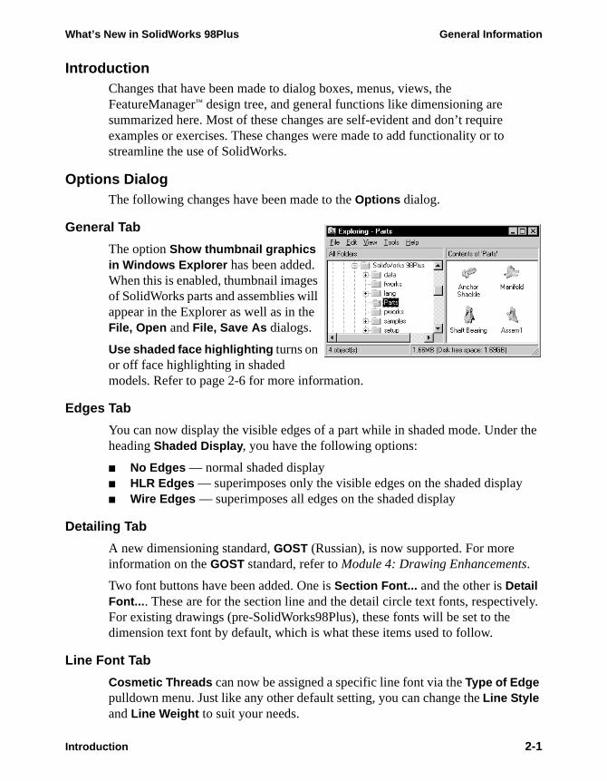
The option Show thumbnail graphics in Windows Explorer has been added. When this is enabled, thumbnail images of SolidWorks parts and assemblies will appear in the Explorer as well as in the File, Open and File, Save As dialogs.
Use shaded face highlighting turns on or off face highlighting in shaded models. Refer to page 2-6 for more information.
Edges Tab
You can now display the visible edges of a part while in shaded mode. Undeheading Shaded Display, you have the following options:
■ No Edges — normal shaded display■ HLR Edges — superimposes only the visible edges on the shaded displa■ Wire Edges — superimposes all edges on the shaded display
Detailing Tab
A new dimensioning standard, GOST (Russian), is now supported. For more information on the GOST standard, refer to Module 4: Drawing Enhancements.
Two font buttons have been added. One is Section Font... and the other is Detail Font.... These are for the section line and the detail circle text fonts, respectivFor existing drawings (pre-SolidWorks98Plus), these fonts will be set to the dimension text font by default, which is what these items used to follow.
Line Font Tab
Cosmetic Threads can now be assigned a specific line font via the Type of Edge pulldown menu. Just like any other default setting, you can change the Line Style and Line Weight to suit your needs.
Introduction 2-1
General Information What’s New in SolidWorks 98Plus
k ve.
ons,
t in
es
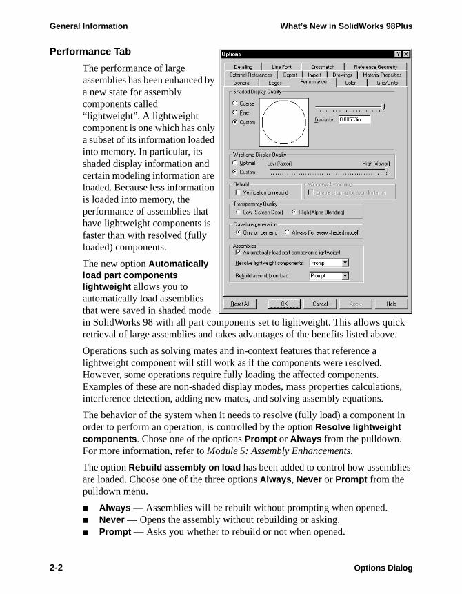
Performance Tab
The performance of large assemblies has been enhanced by a new state for assembly components called “lightweight”. A lightweight component is one which has only a subset of its information loaded into memory. In particular, its shaded display information and certain modeling information are loaded. Because less information is loaded into memory, the performance of assemblies that have lightweight components is faster than with resolved (fully loaded) components.
The new option Automatically load part components lightweight allows you to automatically load assemblies that were saved in shaded mode in SolidWorks 98 with all part components set to lightweight. This allows quicretrieval of large assemblies and takes advantages of the benefits listed abo
Operations such as solving mates and in-context features that reference a lightweight component will still work as if the components were resolved. However, some operations require fully loading the affected components. Examples of these are non-shaded display modes, mass properties calculatiinterference detection, adding new mates, and solving assembly equations.
The behavior of the system when it needs to resolve (fully load) a componenorder to perform an operation, is controlled by the option Resolve lightweight components. Chose one of the options Prompt or Always from the pulldown. For more information, refer to Module 5: Assembly Enhancements.
The option Rebuild assembly on load has been added to control how assembliare loaded. Choose one of the three options Always, Never or Prompt from the pulldown menu.
■ Always — Assemblies will be rebuilt without prompting when opened.■ Never — Opens the assembly without rebuilding or asking.■ Prompt — Asks you whether to rebuild or not when opened.
2-2 Options Dialog
What’s New in SolidWorks 98Plus General Information
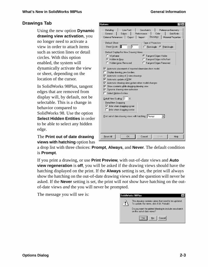
Drawings Tab
Using the new option Dynamic drawing view activation, you no longer need to activate a view in order to attach items such as section lines or detail circles. With this option enabled, the system will dynamically activate the view or sheet, depending on the location of the cursor.
In SolidWorks 98Plus, tangent edges that are removed from display will, by default, not be selectable. This is a change in behavior compared to SolidWorks 98. Use the option Select Hidden Entities in order to be able to select any hidden edge.
The Print out of date drawing views with hatching option has a drop list with three choices: Prompt, Always, and Never. The default condition is Prompt.
If you print a drawing, or use Print Preview, with out-of-date views and Auto view regeneration is off, you will be asked if the drawing views should have the hatching displayed on the print. If the Always setting is set, the print will always show the hatching on the out-of-date drawing views and the question will never be asked. If the Never setting is set, the print will not show have hatching on the out-of-date views and the you will never be prompted.
The message you will see is:
Options Dialog 2-3

General Information What’s New in SolidWorks 98Plus
External References Tab
The options listed under Show folders for now includes a setting Palette form tools. This controls the search path for a library of sheet metal form features such as louvers, lances, and dimples. For more information about form features for sheet metal, refer to Module 3: Modeling Enhancements.
The option Load referenced documents has been added to control whether externally referenced files, such as base parts or in-context features, are loaded into memory when a file referencing them is opened. Choose one of the three options Always, Never or Prompt from the pulldown menu.
2-4 Options Dialog
What’s New in SolidWorks 98Plus General Information
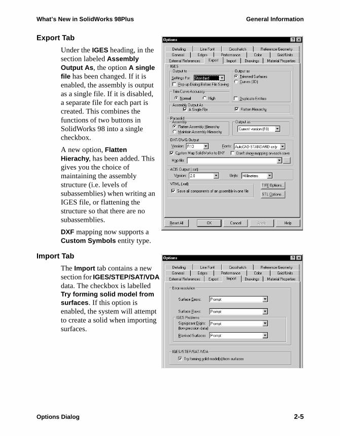
Export Tab
Under the IGES heading, in the section labeled Assembly Output As, the option A single file has been changed. If it is enabled, the assembly is output as a single file. If it is disabled, a separate file for each part is created. This combines the functions of two buttons in SolidWorks 98 into a single checkbox.
A new option, Flatten Hierachy, has been added. This gives you the choice of maintaining the assembly structure (i.e. levels of subassemblies) when writing an IGES file, or flattening the structure so that there are no subassemblies.
DXF mapping now supports a Custom Symbols entity type.
Import Tab
The Import tab contains a new section for IGES/STEP/SAT/VDA data. The checkbox is labelled Try forming solid model from surfaces. If this option is enabled, the system will attempt to create a solid when importing surfaces.
Options Dialog 2-5
General Information What’s New in SolidWorks 98Plus
HighlightingWhen you select a face of a shaded model, it gets highlighted in the highlight color (green by default). You can change the highlight color through Tools, Options, Color. You can turn this option off through Tools, Options, General.
FeatureManager Design TreeNow the FeatureManager design tree can be searched for a feature name or some portion of it. When the string is found, it is scrolled into view. The same can also be accomplished with a graphic selection.
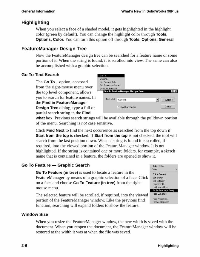
Go To Text Search
The Go To... option, accessed from the right-mouse menu over the top level component, allows you to search for feature names. In the Find in FeatureManager Design Tree dialog, type a full or partial search string in the Find what box. Previous search strings will be available through the pulldown portion of the menu. Searching is not case sensitive.
Click Find Next to find the next occurrence as searched from the top down if Start from the top is checked. If Start from the top is not checked, the tool will search from the last position down. When a string is found it is scrolled, if required, into the viewed portion of the FeatureManager window. It is not highlighted. If the string is contained one or more folders, for example, a sketch name that is contained in a feature, the folders are opened to show it.
Go To Feature — Graphic Search
Go To Feature (in tree) is used to locate a feature in the FeatureManager by means of a graphic selection of a face. Click on a face and choose Go To Feature (in tree) from the right-mouse menu.
The selected feature will be scrolled, if required, into the viewed portion of the FeatureManager window. Like the previous find function, searching will expand folders to show the feature.
Window Size
When you resize the FeatureManager window, the new width is saved with the document. When you reopen the document, the FeatureManager window will be restored at the width it was at when the file was saved.
2-6 Highlighting
What’s New in SolidWorks 98Plus General Information
es.
e
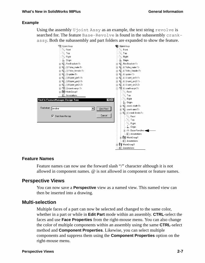
Example
Using the assembly Ujoint Assy as an example, the text string revolve is searched for. The feature Base-Revolve is found in the subassembly crank-assy. Both the subassembly and part folders are expanded to show the feature.
Feature Names
Feature names can now use the forward slash “/” character although it is notallowed in component names. @ is not allowed in component or feature nam
Perspective ViewsYou can now save a Perspective view as a named view. This named view can then be inserted into a drawing.
Multi-selectionMultiple faces of a part can now be selected and changed to the same color,whether in a part or while in Edit Part mode within an assembly. CTRL-select the faces and use Face Properties from the right-mouse menu. You can also changthe color of multiple components within an assembly using the same CTRL-select method and Component Properties. Likewise, you can select multiple components and suppress them using the Component Properties option on the right-mouse menu.
Perspective Views 2-7
General Information What’s New in SolidWorks 98Plus
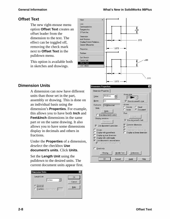
Offset TextThe new right-mouse menu option Offset Text creates an offset leader from the dimension to the text. The effect can be toggled off, removing the check mark next to Offset Text in the pulldown menu.
This option is available both in sketches and drawings.
Dimension UnitsA dimension can now have different units than those set in the part, assembly or drawing. This is done on an individual basis using the dimension’s Properties. For example, this allows you to have both Inch and Feet&Inch dimensions in the same part or on the same drawing. It also allows you to have some dimensions display in decimals and others in fractions.
Under the Properties of a dimension, deselect the checkbox Use document’s units . Click Units .
Set the Length Unit using the pulldown to the desired units. The current document units appear first.
2-8 Offset Text

What’s New in SolidWorks 98Plus General Information
Reference DimensionsWhen you double-click on a reference dimension, the system opens the Dimension Properties dialog. This is the case whether you are in a part, assembly, or drawing.
ToolbarsA number of changes have been made to toolbars and their buttons. In some cases entire new toolbars have been added to improve access to commonly used commands. In other cases, tools have been redrawn to make their meaning and function clearer and new tools have been created for new operations.
As always, you can customize your user interface using Tools, Customize.
Dependency Editing
This toolbar has been removed. Its tools have been redesigned and placed on the Features toolbar. The new tools are:
Edit, Suppress
Edit, Unsuppress
Edit, Unsuppress with Dependents
Features
As mentioned above, the Dependency Editing toolbar has been eliminated and its buttons moved to the Features toolbar. In addition, some new buttons have been added. The new functionality represented by these tools is discussed in Module 3: Modeling Enhancements.
Insert, Features, Hole, Simple
Insert, Features, Hole, Wizard
Insert, Features, Shape
Insert, Reference Geometry, Coordinate System
Insert, Reference Geometry, Composite Curve
Insert, Reference Geometry, Curve Through Reference Points (Not a
new function. It just never had an tool before.)
Move/Size Features (Not a new function. Just a redesigned tool.)
Reference Dimensions 2-9
General Information What’s New in SolidWorks 98Plus
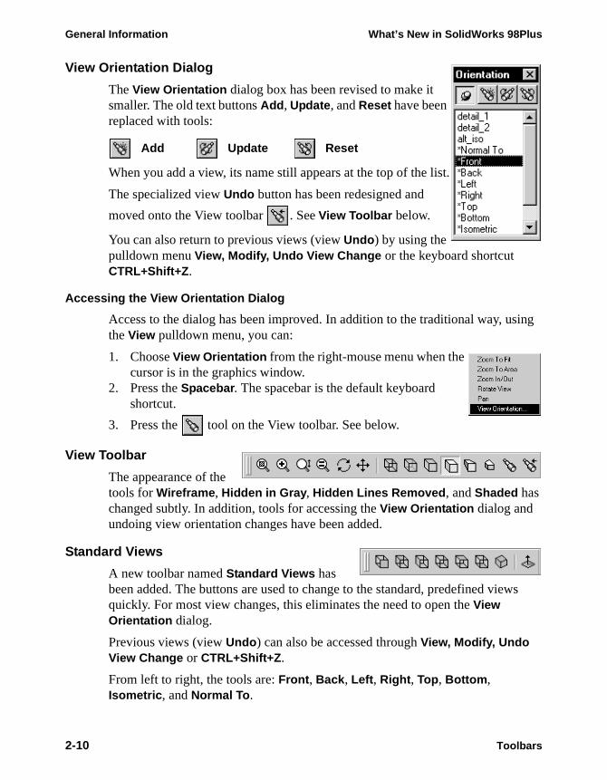
View Orientation Dialog
The View Orientation dialog box has been revised to make it smaller. The old text buttons Add, Update, and Reset have been replaced with tools:
Add Update Reset
When you add a view, its name still appears at the top of the list.
The specialized view Undo button has been redesigned and
moved onto the View toolbar . See View Toolbar below.
You can also return to previous views (view Undo) by using the pulldown menu View, Modify, Undo View Change or the keyboard shortcut CTRL+Shift+Z.
Accessing the View Orientation Dialog
Access to the dialog has been improved. In addition to the traditional way, using the View pulldown menu, you can:
1. Choose View Orientation from the right-mouse menu when the cursor is in the graphics window.
2. Press the Spacebar. The spacebar is the default keyboard shortcut.
3. Press the tool on the View toolbar. See below.
View Toolbar
The appearance of the tools for Wireframe, Hidden in Gray, Hidden Lines Removed, and Shaded has changed subtly. In addition, tools for accessing the View Orientation dialog and undoing view orientation changes have been added.
Standard Views
A new toolbar named Standard Views has been added. The buttons are used to change to the standard, predefined views quickly. For most view changes, this eliminates the need to open the View Orientation dialog.
Previous views (view Undo) can also be accessed through View, Modify, Undo View Change or CTRL+Shift+Z.
From left to right, the tools are: Front, Back, Left, Right, Top, Bottom, Isometric, and Normal To.
2-10 Toolbars

What’s New in SolidWorks 98Plus General Information
on
cts.
Selection Filter Toolbar
The selection filter pulldown menu in SolidWorks 98, with its limited set of filters, has been replaced with a selection filter toolbar. Like most toolbars, you can dock it vertically or horizontally along the edge of the screen, or position it as separate window inside the graphics area. For illustration purposes and to conserve space in this book, it is shown as a separate window.
When a selection filter is on, the cursor changes like this: .
Accessing the Toolbar
All toolbars, including this one, can be accessed by placing the cursor in the toolbar area of the SolidWorks window and pressing the right mouse button. Choose Selection Filters from the menu. You can also turn the Selection Filters
toolbar on and off using the icon on the Main toolbar.
How Filters Work
You can control which objects are selectable by turning on some, all, or no selection filters. The three tools located at the top of the filter menu have specialized functions which are explained below. Those with keyboard shortcuts (case sensitive) have them indicated in parentheses.
Toggle Selection Filters — This enables/disables whatever set of selecti
filters you have picked. (F6)
Clear All Filters — This deselects all filters.
Select All Filters — This turns on all the filters.
The remaining buttons represent filters for specific types of geometry or objePositioning the cursor over a filter will display a tooltip explaining its function.
Vertices (v)
Edges (e)
Faces (x)
Axes
Planes
Points
Sketch Segments
Midpoints
Centermarks
Dimensions
Finish Symbols
Geometric Tolerance
Notes and Balloons
Datum Features
Weld Symbols
Datum Targets
Cosmetic Threads
Toolbars 2-11
General Information What’s New in SolidWorks 98Plus
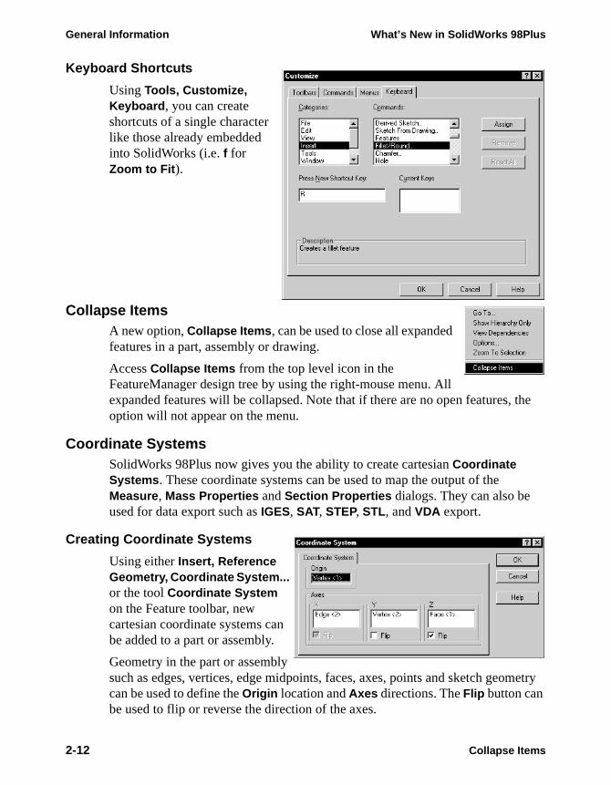
Keyboard Shortcuts
Using Tools, Customize, Keyboard, you can create shortcuts of a single character like those already embedded into SolidWorks (i.e. f for Zoom to Fit).
Collapse ItemsA new option, Collapse Items, can be used to close all expanded features in a part, assembly or drawing.
Access Collapse Items from the top level icon in the FeatureManager design tree by using the right-mouse menu. All expanded features will be collapsed. Note that if there are no open features, the option will not appear on the menu.
Coordinate SystemsSolidWorks 98Plus now gives you the ability to create cartesian Coordinate Systems. These coordinate systems can be used to map the output of the Measure, Mass Properties and Section Properties dialogs. They can also be used for data export such as IGES, SAT, STEP, STL, and VDA export.
Creating Coordinate Systems
Using either Insert, Reference Geometry, Coordinate System... or the tool Coordinate System on the Feature toolbar, new cartesian coordinate systems can be added to a part or assembly.
Geometry in the part or assembly such as edges, vertices, edge midpoints, faces, axes, points and sketch geometry can be used to define the Origin location and Axes directions. The Flip button can be used to flip or reverse the direction of the axes.
2-12 Collapse Items
What’s New in SolidWorks 98Plus General Information
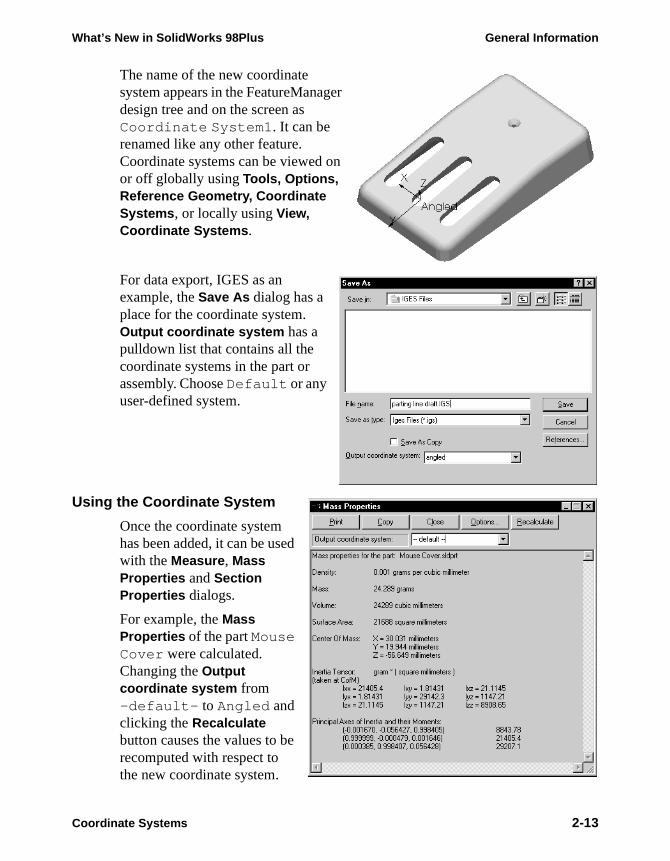
The name of the new coordinate system appears in the FeatureManager design tree and on the screen as Coordinate System1. It can be renamed like any other feature. Coordinate systems can be viewed on or off globally using Tools, Options, Reference Geometry, Coordinate Systems, or locally using View, Coordinate Systems.
For data export, IGES as an example, the Save As dialog has a place for the coordinate system. Output coordinate system has a pulldown list that contains all the coordinate systems in the part or assembly. Choose Default or any user-defined system.
Using the Coordinate System
Once the coordinate system has been added, it can be used with the Measure, Mass Properties and Section Properties dialogs.
For example, the Mass Properties of the part Mouse Cover were calculated. Changing the Output coordinate system from -default- to Angled and clicking the Recalculate button causes the values to be recomputed with respect to the new coordinate system.
Coordinate Systems 2-13

General Information What’s New in SolidWorks 98Plus
Similar options exist in the Tools, Measure and Section Properties dialogs.
1 Open the part.Open the existing part coord_system in the What’s New directory.
2-14 Coordinate Systems
What’s New in SolidWorks 98Plus General Information
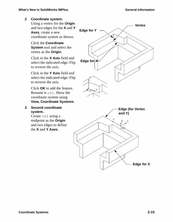
2 Coordinate system.Using a vertex for the Origin and two edges for the X and Y Axes, create a new coordinate system as shown.
Click the Coordinate System tool and select the vertex as the Origin.
Click in the X Axis field and select the indicated edge. Flip to reverse the axis.
Click in the Y Axis field and select the indicated edge. Flip to reverse the axis.
Click OK to add the feature. Rename it cs1. Show the coordinate system using View, Coordinate Systems.
3 Second coordinate system.Create cs2 using a midpoint as the Origin and two edges to define the X and Y Axes.
Vertex
Edge for X
Edge for Y
Edge (for Vertexand Y)
Edge for X
Coordinate Systems 2-15
General Information What’s New in SolidWorks 98Plus
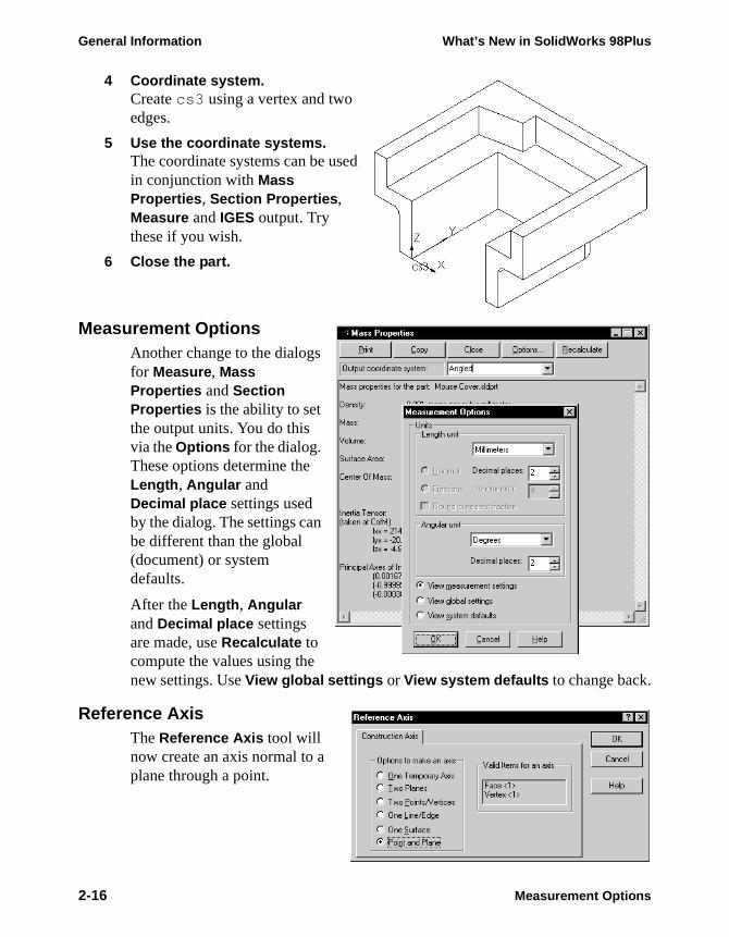
4 Coordinate system.Create cs3 using a vertex and two edges.
5 Use the coordinate systems.The coordinate systems can be used in conjunction with Mass Properties, Section Properties, Measure and IGES output. Try these if you wish.
6 Close the part.
Measurement OptionsAnother change to the dialogs for Measure, Mass Properties and Section Properties is the ability to set the output units. You do this via the Options for the dialog. These options determine the Length, Angular and Decimal place settings used by the dialog. The settings can be different than the global (document) or system defaults.
After the Length, Angular and Decimal place settings are made, use Recalculate to compute the values using the new settings. Use View global settings or View system defaults to change back.
Reference AxisThe Reference Axis tool will now create an axis normal to a plane through a point.
2-16 Measurement Options

What’s New in SolidWorks 98Plus General Information
Select a planar face or plane in conjunction with a vertex or endpoint. Use the Point and Plane option to create the axis.
Feature Palette™ WindowThe Feature Palette window has changed in appearance. It is now displayed as a palette page with folders. A small set of navigation tools includes Back and Forward arrows to move through folder levels, a Reload and a Home button. The folders display an icon of a part (Palette Parts), a library feature (Palette Features) or a form feature on them.
The icons can be viewed large or small using the right-mouse menu within the window. Note that only the large option shows pictures of the features.
Point (vertex)
Plane (face)
Feature Palette™ Window 2-17
General Information What’s New in SolidWorks 98Plus
Using the Palette
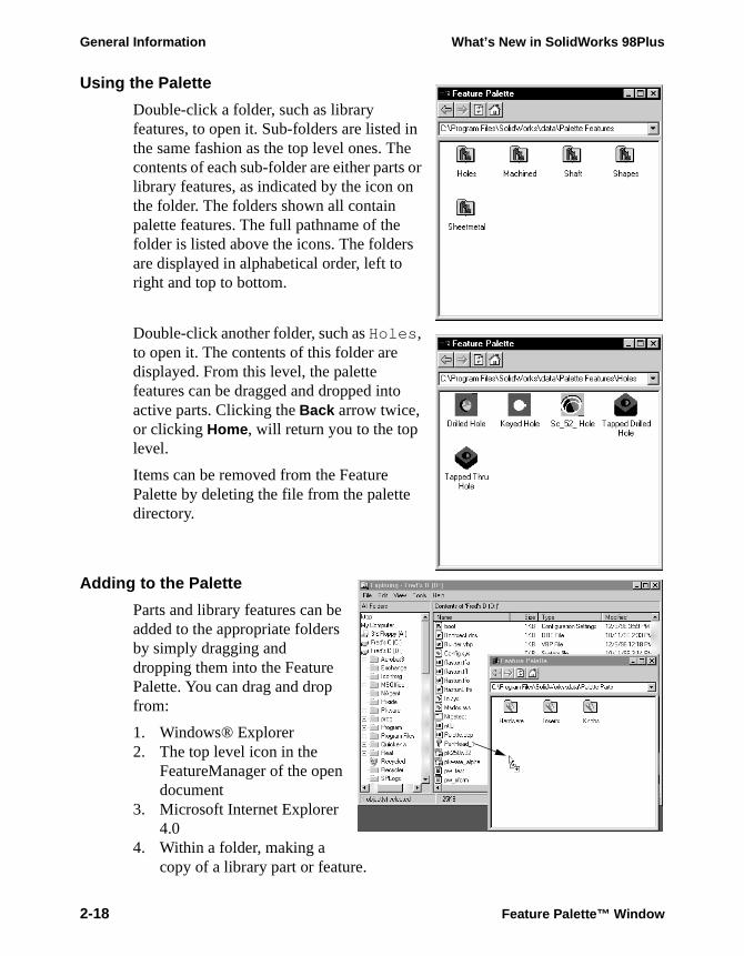
Double-click a folder, such as library features, to open it. Sub-folders are listed in the same fashion as the top level ones. The contents of each sub-folder are either parts or library features, as indicated by the icon on the folder. The folders shown all contain palette features. The full pathname of the folder is listed above the icons. The folders are displayed in alphabetical order, left to right and top to bottom.
Double-click another folder, such as Holes, to open it. The contents of this folder are displayed. From this level, the palette features can be dragged and dropped into active parts. Clicking the Back arrow twice, or clicking Home, will return you to the top level.
Items can be removed from the Feature Palette by deleting the file from the palette directory.
Adding to the Palette
Parts and library features can be added to the appropriate folders by simply dragging and dropping them into the Feature Palette. You can drag and drop from:
1. Windows® Explorer2. The top level icon in the
FeatureManager of the open document
3. Microsoft Internet Explorer 4.0
4. Within a folder, making a copy of a library part or feature.
2-18 Feature Palette™ Window
What’s New in SolidWorks 98Plus General Information
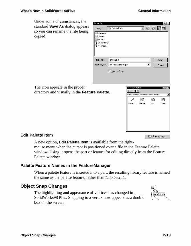
Under some circumstances, the standard Save As dialog appears so you can rename the file being copied.
The icon appears in the proper directory and visually in the Feature Palette.
Edit Palette Item
A new option, Edit Palette Item is available from the right-mouse menu when the cursor is positioned over a file in the Feature Palette window. Using it opens the part or feature for editing directly from the Feature Palette window.
Palette Feature Names in the FeatureManager
When a palette feature is inserted into a part, the resulting library feature is named the same as the palette feature, rather than Libfeat1.
Object Snap ChangesThe highlighting and appearance of vertices has changed in SolidWorks98 Plus. Snapping to a vertex now appears as a double box on the screen.
Object Snap Changes 2-19
General Information What’s New in SolidWorks 98Plus
Drag and Drop from Internet ExplorerSolidWorks part files can now be dragged and dropped from Internet Explorer to:
■ Feature Palette■ New Part■ Drawing■ Assembly
If the file is dropped into a drawing or an assembly, you will be prompted to name the new file on your local disk.
Importing and Exporting DataFor ease of reference, the enhancements to importing and exporting data are listed here, in one section.
IGES
■ When importing, surfaces and curves can be filtered by layer.■ When exporting, you can do so relative to user-defined coordinate systems.■ You can import 2D data into a sketch.■ You can export selected components, including subassemblies, from within an
assembly.■ You can control whether or not the system tries to knit surfaces during import.
SAT
■ You can export selected faces or reference surfaces.■ You can control whether or not the system tries to knit surfaces during import.
STEP
■ You can export selected faces or reference surfaces.■ You can control whether or not the system tries to knit surfaces during import.■ Importing supports STEP AP214.
Parasolids (X_T and X_B)
■ You can import or export face colors for parts and component colors for assemblies.
■ You can import and export component names for assemblies.
VDA
■ You can export selected faces or reference surfaces.■ You can control whether or not the system tries to knit surfaces during import.
2-20 Drag and Drop from Internet Explorer

What’s New in SolidWorks 98Plus General Information
Service PacksA new option, Service Packs, is available under the Help menu. This allows you to conveniently check for new service packs and initiate downloading them. When you pick this option, you default browser will be launched into the support area of the SolidWorks web site. You also have the option to have Solidworks check for service packs once per week on start-up.
Note: Downloading service packs from the SolidWorks web site is a benefit that is only available to customers who have purchased the SolidWorks Subscription Service.
Converting FilesAny files opened in SolidWorks 98Plus will automatically convert to the updated format and once saved will not be backward-compatible.
The first time you open a pre-Solidworks98Plus file, it may take longer than normal. Once the file has been opened and saved, the subsequent time needed to open the file will return to normal.
You can use the new Conversion Wizard to convert all your files to SolidWorks 98Plus format. This can be found in the SolidWorks program group on the Windows Start menu. Since this tool will overwrite the existing files, it gives you the option to make a back-up copy of the files. You can also control whether SolidWorks will run in an open window or in background.
Service Packs 2-21

General Information What’s New in SolidWorks 98Plus
2-22 Converting Files
What’s New in SolidWorks 98Plus
Module 3Modeling Enhancements


What’s New in SolidWorks 98Plus Modeling Enhancements
SketchingBelow is a list of the new features and enhancements that have been added to Sketching in SolidWorks 98Plus. Some of these are illustrated in more depth in examples later in this module. They are listed here in one place with a short description for your convenience and ease of reference.
Parabola
The sketch option Parabola has been added for SolidWorks98Plus. It has four control points: two endpoints, a center and a focus point.
The Parabola is created by a method similar to the Centerpoint Arc. You press the mouse button to locate the center and drag outward to locate the focus. Release the mouse button. Then press the mouse button again and drag to position the endpoints. All the control points can then be dragged, dimensioned, or related within the sketch.
1 Sketch a parabola.
Select the Parabola option from Tools, Sketch Entity or pick the button on
the Sketch Tools toolbar. The cursor changes to display the parabola symbol .
If the tool is not on the tool bar you can add it using Tools, Customize.
2 Locate the center and the focus.Position the cursor at the Centerpoint location (the Origin in this example) and drag away to define the location of the Focus. The parabola will be formed in temporary (blue dotted) graphics.
Endpoints
Center
Focus
Sketching 3-1
Modeling Enhancements What’s New in SolidWorks 98Plus
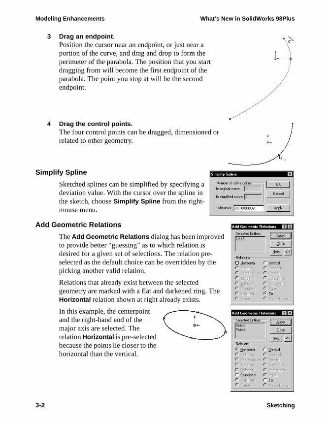
3 Drag an endpoint.Position the cursor near an endpoint, or just near a portion of the curve, and drag and drop to form the perimeter of the parabola. The position that you start dragging from will become the first endpoint of the parabola. The point you stop at will be the second endpoint.
4 Drag the control points.The four control points can be dragged, dimensioned or related to other geometry.
Simplify Spline
Sketched splines can be simplified by specifying a deviation value. With the cursor over the spline in the sketch, choose Simplify Spline from the right-mouse menu.
Add Geometric Relations
The Add Geometric Relations dialog has been improved to provide better “guessing” as to which relation is desired for a given set of selections. The relation pre-selected as the default choice can be overridden by the picking another valid relation.
Relations that already exist between the selected geometry are marked with a flat and darkened ring. The Horizontal relation shown at right already exists.
In this example, the centerpoint and the right-hand end of the major axis are selected. The relation Horizontal is pre-selected because the points lie closer to the horizontal than the vertical.
3-2 Sketching

What’s New in SolidWorks 98Plus Modeling Enhancements
In the second example, the centerpoint and the upper end of the minor axis are chosen. Vertical is chosen as the default relation based on the objects selected and their positions.
Revolved Features
Revolved features, whether a boss or cut, now support multiple sketch profiles. This is consistent with the behavior of extruded features.
LoftingNow 3D profiles can be used in a Loft operation. Previously, only sketches could be used.
The 3D profile is created using the Split Line option which projects a sketch onto a face. The resulting geometry is a new face.
You must select the new face, not the edges or feature, to use the 3D curve. Select on the face near the desired vertex location.
The resulting Loft (a boss in this example) is added to the solid.
non-printing
Face
Lofting 3-3
Modeling Enhancements What’s New in SolidWorks 98Plus
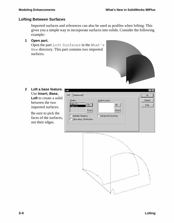
Lofting Between Surfaces
Imported surfaces and references can also be used as profiles when lofting. This gives you a simple way to incorporate surfaces into solids. Consider the following example:
1 Open part.Open the part Loft Surfaces in the What’s New directory. This part contains two imported surfaces.
2 Loft a base feature.Use Insert, Base, Loft to create a solid between the two imported surfaces.
Be sure to pick the faces of the surfaces, not their edges.
3-4 Lofting
What’s New in SolidWorks 98Plus Modeling Enhancements
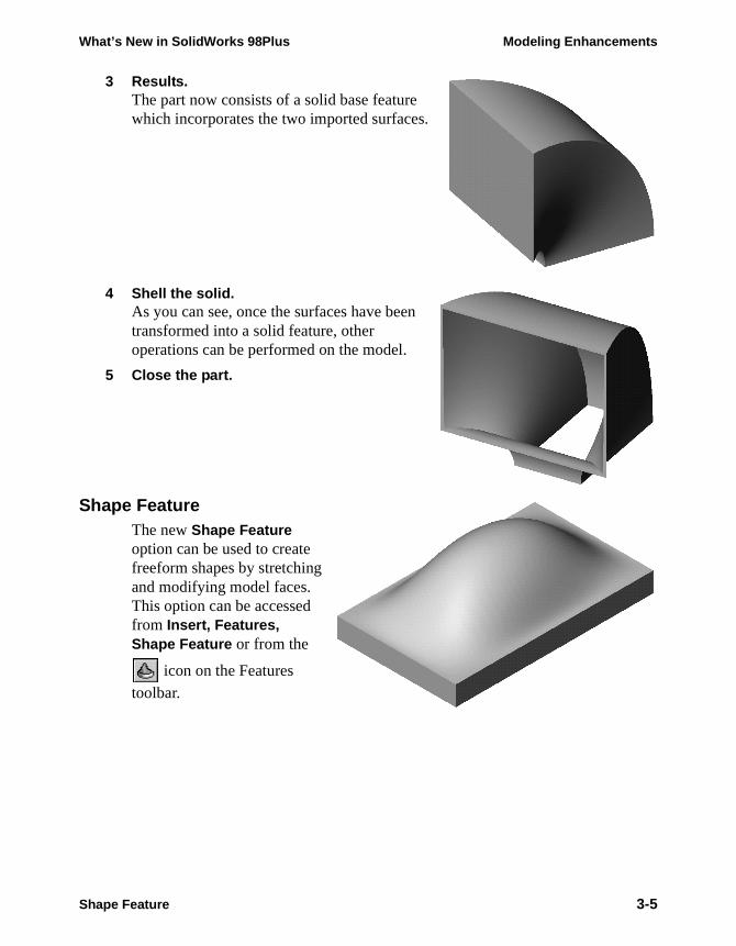
3 Results.The part now consists of a solid base feature which incorporates the two imported surfaces.
4 Shell the solid.As you can see, once the surfaces have been transformed into a solid feature, other operations can be performed on the model.
5 Close the part.
Shape FeatureThe new Shape Feature option can be used to create freeform shapes by stretching and modifying model faces. This option can be accessed from Insert, Features, Shape Feature or from the
icon on the Features
toolbar.
Shape Feature 3-5
Modeling Enhancements What’s New in SolidWorks 98Plus
it.
has
ore
iff.
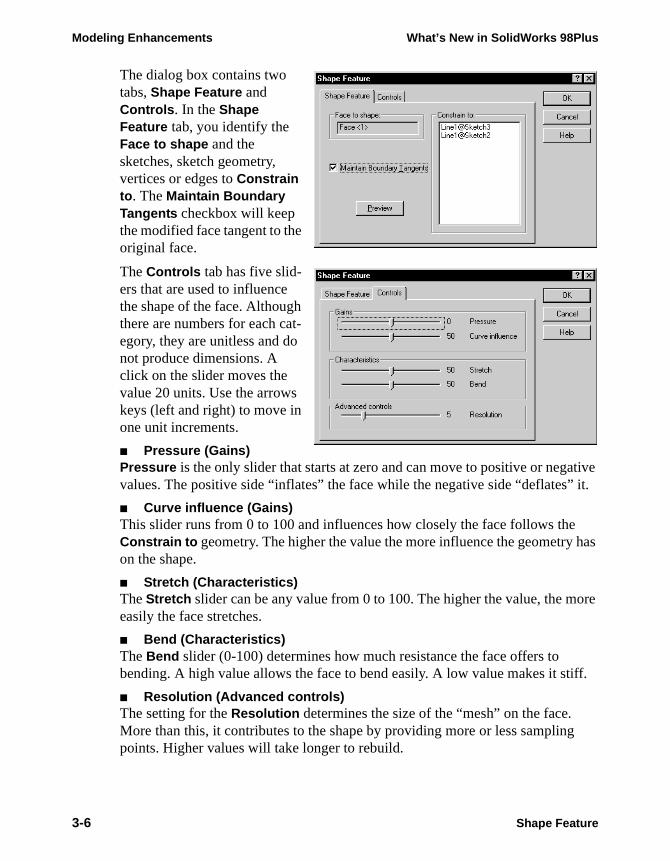
The dialog box contains two tabs, Shape Feature and Controls. In the Shape Feature tab, you identify the Face to shape and the sketches, sketch geometry, vertices or edges to Constrain to. The Maintain Boundary Tangents checkbox will keep the modified face tangent to the original face.
The Controls tab has five slid-ers that are used to influence the shape of the face. Although there are numbers for each cat-egory, they are unitless and do not produce dimensions. A click on the slider moves the value 20 units. Use the arrows keys (left and right) to move in one unit increments.
■ Pressure (Gains)Pressure is the only slider that starts at zero and can move to positive or negative values. The positive side “inflates” the face while the negative side “deflates”
■ Curve influence (Gains)This slider runs from 0 to 100 and influences how closely the face follows theConstrain to geometry. The higher the value the more influence the geometryon the shape.
■ Stretch (Characteristics)The Stretch slider can be any value from 0 to 100. The higher the value, the measily the face stretches.
■ Bend (Characteristics)The Bend slider (0-100) determines how much resistance the face offers to bending. A high value allows the face to bend easily. A low value makes it st
■ Resolution (Advanced controls)The setting for the Resolution determines the size of the “mesh” on the face. More than this, it contributes to the shape by providing more or less samplingpoints. Higher values will take longer to rebuild.
3-6 Shape Feature
What’s New in SolidWorks 98Plus Modeling Enhancements
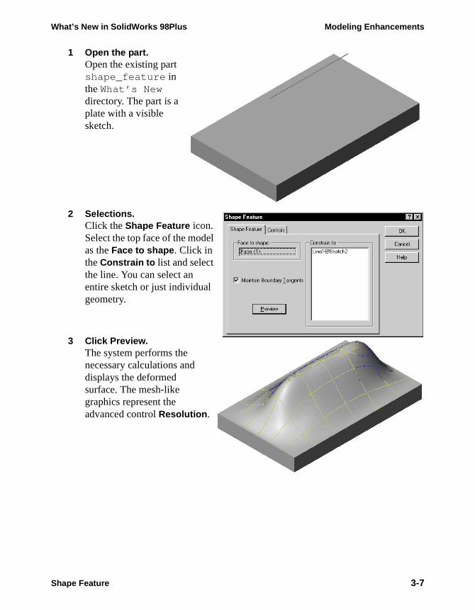
1 Open the part.Open the existing part shape_feature in the What’s New directory. The part is a plate with a visible sketch.
2 Selections.Click the Shape Feature icon. Select the top face of the model as the Face to shape. Click in the Constrain to list and select the line. You can select an entire sketch or just individual geometry.
3 Click Preview.The system performs the necessary calculations and displays the deformed surface. The mesh-like graphics represent the advanced control Resolution.
Shape Feature 3-7
Modeling Enhancements What’s New in SolidWorks 98Plus
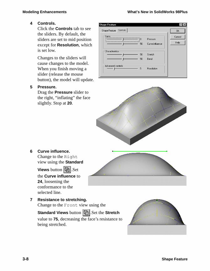
4 Controls.Click the Controls tab to see the sliders. By default, the sliders are set to mid position except for Resolution, which is set low.
Changes to the sliders will cause changes to the model. When you finish moving a slider (release the mouse button), the model will update.
5 Pressure.Drag the Pressure slider to the right, “inflating” the face slightly. Stop at 20.
6 Curve influence.Change to the Right view using the Standard
Views button .Set
the Curve influence to 24, loosening the conformance to the selected line.
7 Resistance to stretching.Change to the Front view using the
Standard Views button .Set the Stretch
value to 75, decreasing the face’s resistance to being stretched.
3-8 Shape Feature
What’s New in SolidWorks 98Plus Modeling Enhancements
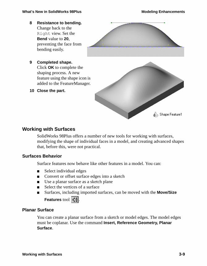
8 Resistance to bending.Change back to the Right view. Set the Bend value to 20, preventing the face from bending easily.
9 Completed shape.Click OK to complete the shaping process. A new feature using the shape icon is added to the FeatureManager.
10 Close the part.
Working with SurfacesSolidWorks 98Plus offers a number of new tools for working with surfaces, modifying the shape of individual faces in a model, and creating advanced shapes that, before this, were not practical.
Surfaces Behavior
Surface features now behave like other features in a model. You can:
■ Select individual edges■ Convert or offset surface edges into a sketch■ Use a planar surface as a sketch plane■ Select the vertices of a surface■ Surfaces, including imported surfaces, can be moved with the Move/Size
Features tool .
Planar Surface
You can create a planar surface from a sketch or model edges. The model edges must be coplanar. Use the command Insert, Reference Geometry, Planar Surface.
non-printing
Working with Surfaces 3-9
Modeling Enhancements What’s New in SolidWorks 98Plus
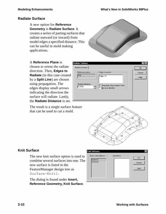
Radiate Surface
A new option for Reference Geometry is Radiate Surface. It creates a series of parting surfaces that radiate outward (or inward) from model edges a specified distance. This can be useful in mold making applications.
A Reference Plane is chosen to orient the radiate direction. Then, Edges to Radiate (in this case created by a Split Line) are chosen using propagation. The edges display small arrows indicating the direction the surface will radiate. Lastly, the Radiate Distance is set.
The result is a single surface feature that can be used to cut a mold.
Knit Surface
The new knit surface option is used to combine several surfaces into one. The new surface is listed in the FeatureManager design tree as Surface-Knit1.
The dialog is found under Insert, Reference Geometry, Knit Surface.
3-10 Working with Surfaces

What’s New in SolidWorks 98Plus Modeling Enhancements
Example
The following example illustrates how Radiate Surface and Knit Surface can be used together to create a core for an injection mold. In this case, the part being molded is a small plastic button.
1 Open part.Open the existing part Button in the What’s New directory.
2 Radiate SurfaceFrom the Insert menu, choose Reference Geometry, Radiate Surface. Select the Top reference plane. Then select the outside edge of the Button as the Edge to propagate. Set the Radiate distance to 0.25 and click OK.
3 Results.The resulting surface is shown here in a different color for clarity.
4 Open an assembly.Open a new assembly and drag the Button into it. For convenience, drop it on the assembly origin so it will be fixed and aligned to the default assembly reference planes.
Save the assembly. Name it whatever you want.
5 Insert a new part.Using Insert, Component, New, insert a new part into the assembly. Drop it on Plane1 (Front) of the assembly. When prompted, name this part Core Pin .
Working with Surfaces 3-11
Modeling Enhancements What’s New in SolidWorks 98Plus
6 Exit the sketch.When you insert a new part into an assembly, you are automatically active in a sketch. The next step in the procedure does not require a sketch, so exit it. You should be in Edit Part mode, editing the Core Pin.
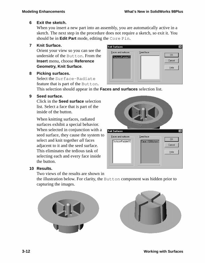
7 Knit Surface.Orient your view so you can see the underside of the Button. From the Insert menu, choose Reference Geometry, Knit Surface.
8 Picking surfaces.Select the Surface-Radiate feature that is part of the Button. This selection should appear in the Faces and surfaces selection list.
9 Seed surface.Click in the Seed surface selection list. Select a face that is part of the inside of the button.
When knitting surfaces, radiated surfaces exhibit a special behavior. When selected in conjunction with a seed surface, they cause the system to select and knit together all faces adjacent to it and the seed surface. This eliminates the tedious task of selecting each and every face inside the button.
10 Results.Two views of the results are shown in the illustration below. For clarity, the Button component was hidden prior to capturing the images.
3-12 Working with Surfaces
What’s New in SolidWorks 98Plus Modeling Enhancements
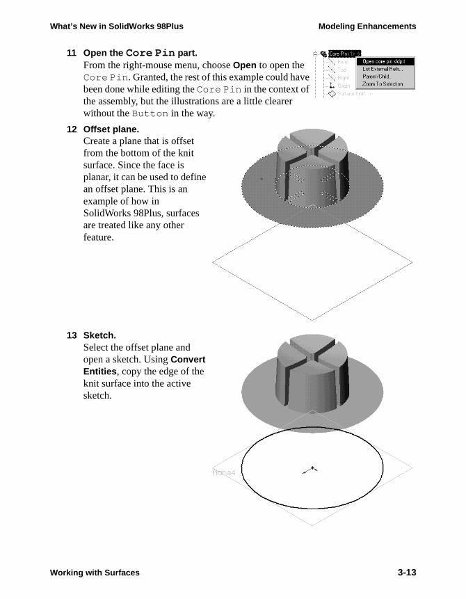
11 Open the Core Pin part.From the right-mouse menu, choose Open to open the Core Pin. Granted, the rest of this example could have been done while editing the Core Pin in the context of the assembly, but the illustrations are a little clearer without the Button in the way.
12 Offset plane.Create a plane that is offset from the bottom of the knit surface. Since the face is planar, it can be used to define an offset plane. This is an example of how in SolidWorks 98Plus, surfaces are treated like any other feature.
13 Sketch.Select the offset plane and open a sketch. Using Convert Entities, copy the edge of the knit surface into the active sketch.
Working with Surfaces 3-13
Modeling Enhancements What’s New in SolidWorks 98Plus
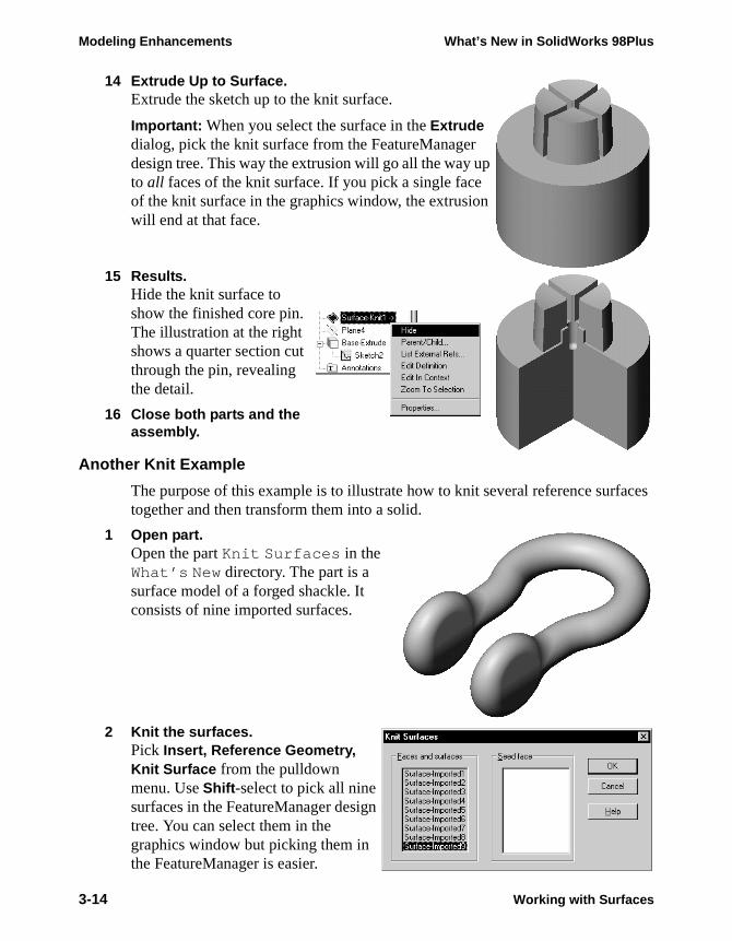
14 Extrude Up to Surface.Extrude the sketch up to the knit surface.
Important: When you select the surface in the Extrude dialog, pick the knit surface from the FeatureManager design tree. This way the extrusion will go all the way up to all faces of the knit surface. If you pick a single face of the knit surface in the graphics window, the extrusion will end at that face.
15 Results.Hide the knit surface to show the finished core pin. The illustration at the right shows a quarter section cut through the pin, revealing the detail.
16 Close both parts and the assembly.
Another Knit Example
The purpose of this example is to illustrate how to knit several reference surfaces together and then transform them into a solid.
1 Open part.Open the part Knit Surfaces in the What’s New directory. The part is a surface model of a forged shackle. It consists of nine imported surfaces.
2 Knit the surfaces.Pick Insert, Reference Geometry, Knit Surface from the pulldown menu. Use Shift-select to pick all nine surfaces in the FeatureManager design tree. You can select them in the graphics window but picking them in the FeatureManager is easier.
3-14 Working with Surfaces
What’s New in SolidWorks 98Plus Modeling Enhancements
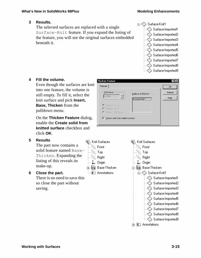
3 Results.The selected surfaces are replaced with a single Surface-Knit feature. If you expand the listing of the feature, you will see the original surfaces embedded beneath it.
4 Fill the volume.Even though the surfaces are knit into one feature, the volume is still empty. To fill it, select the knit surface and pick Insert, Base, Thicken from the pulldown menu.
On the Thicken Feature dialog, enable the Create solid from knitted surface checkbox and click OK.
5 ResultsThe part now contains a solid feature named Base-Thicken. Expanding the listing of this reveals its make-up.
6 Close the part.There is no need to save this so close the part without saving.
Working with Surfaces 3-15
Modeling Enhancements What’s New in SolidWorks 98Plus
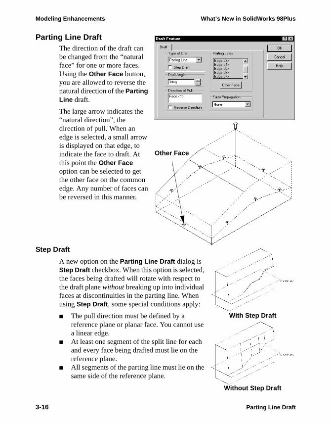
Parting Line DraftThe direction of the draft can be changed from the “natural face” for one or more faces. Using the Other Face button, you are allowed to reverse the natural direction of the Parting Line draft.
The large arrow indicates the “natural direction”, the direction of pull. When an edge is selected, a small arrow is displayed on that edge, to indicate the face to draft. At this point the Other Face option can be selected to get the other face on the common edge. Any number of faces can be reversed in this manner.
Step Draft
A new option on the Parting Line Draft dialog is Step Draft checkbox. When this option is selected, the faces being drafted will rotate with respect to the draft plane without breaking up into individual faces at discontinuities in the parting line. When using Step Draft, some special conditions apply:
■ The pull direction must be defined by a reference plane or planar face. You cannot use a linear edge.
■ At least one segment of the split line for each and every face being drafted must lie on the reference plane.
■ All segments of the parting line must lie on the same side of the reference plane.
Other Face
With Step Draft
Without Step Draft
3-16 Parting Line Draft
What’s New in SolidWorks 98Plus Modeling Enhancements
Working with CurvesNew capabilities for working with curves have been added to SolidWorks 98Plus. These include:
■ Using 3D curves as profiles for lofting■ Creating composite curves■ Reference curves in sketches
Reference Curves
Reference Curve geometry such as imported IGES wireframe entities, can now be selected in SolidWorks. It can then be copied into sketches by Convert Entities and Offset Entities.
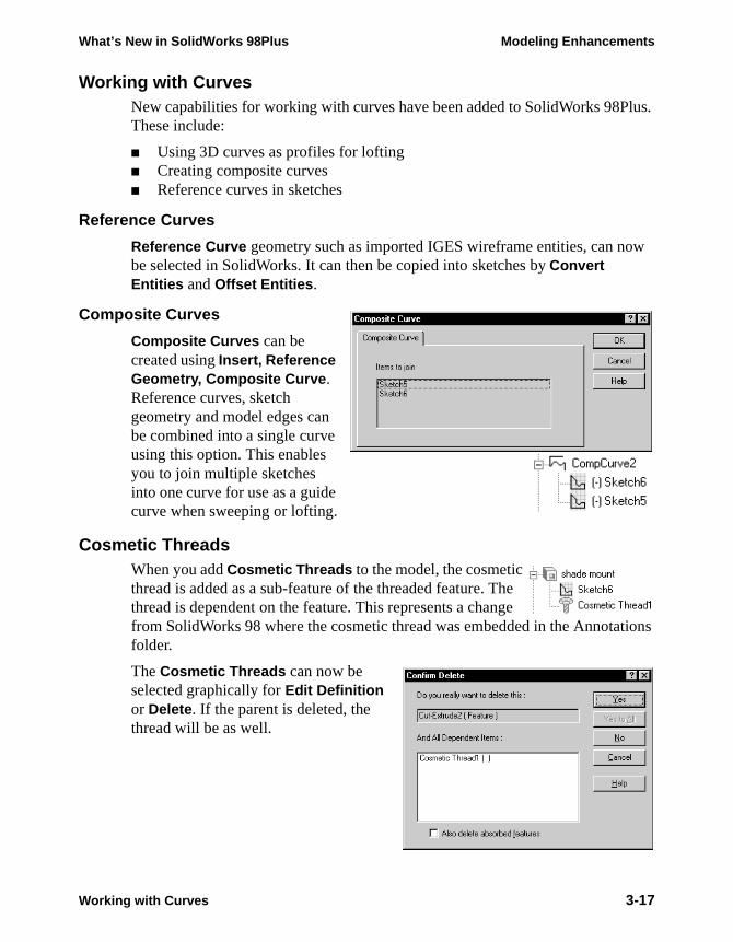
Composite Curves
Composite Curves can be created using Insert, Reference Geometry, Composite Curve. Reference curves, sketch geometry and model edges can be combined into a single curve using this option. This enables you to join multiple sketches into one curve for use as a guide curve when sweeping or lofting.
Cosmetic ThreadsWhen you add Cosmetic Threads to the model, the cosmetic thread is added as a sub-feature of the threaded feature. The thread is dependent on the feature. This represents a change from SolidWorks 98 where the cosmetic thread was embedded in the Annotations folder.
The Cosmetic Threads can now be selected graphically for Edit Definition or Delete. If the parent is deleted, the thread will be as well.
Working with Curves 3-17
Modeling Enhancements What’s New in SolidWorks 98Plus
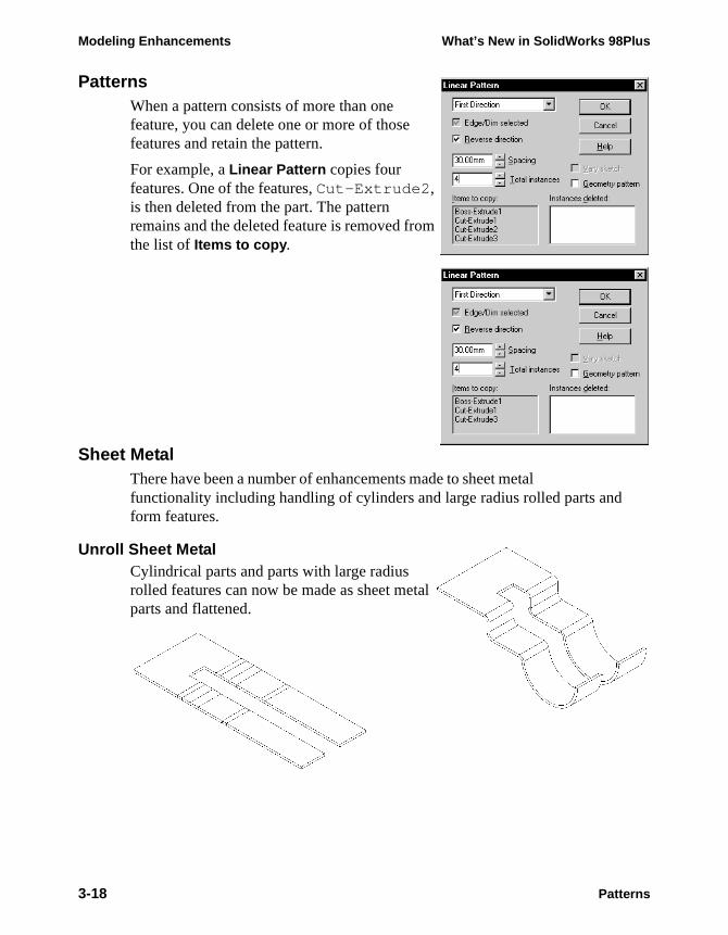
PatternsWhen a pattern consists of more than one feature, you can delete one or more of those features and retain the pattern.
For example, a Linear Pattern copies four features. One of the features, Cut-Extrude2, is then deleted from the part. The pattern remains and the deleted feature is removed from the list of Items to copy.
Sheet MetalThere have been a number of enhancements made to sheet metal functionality including handling of cylinders and large radius rolled parts and form features.
Unroll Sheet MetalCylindrical parts and parts with large radius rolled features can now be made as sheet metal parts and flattened.
non-printing
3-18 Patterns

What’s New in SolidWorks 98Plus Modeling Enhancements
Design Guidelines
To model a cylindrical part so that it can be unrolled you must follow these design guidelines:
■ There must be a slight gap between the ends of the thin material. The best way to achieve this is to sketch and extrude an arc of slightly less than 360°. If needed, you can fill in the gap with a small extrusion later.
■ The end faces must be normal to the cylindrical face. That is, they cannot be beveled as shown at the right.
■ The cylindrical surface must be tangent to the adjoining surfaces. The part shown at the right will not unroll. However, if you fillet the sketch (as in the illustration on page 3-18) the part unrolls without difficulty.
■ The cylindrical face must have four sides. The part at the right has five sides and will not unroll.
Example
1 Sketch the profile.Use the Centerpoint Arc tool to sketch an arc of slightly less than 360°. Dimension the included angle. Use a geometric relation to control the position of one of the ends of the arc. In this case, the right-hand end is positioned a six o’clock or vertically with respect to the circle’s center.
Sheet Metal 3-19
Modeling Enhancements What’s New in SolidWorks 98Plus
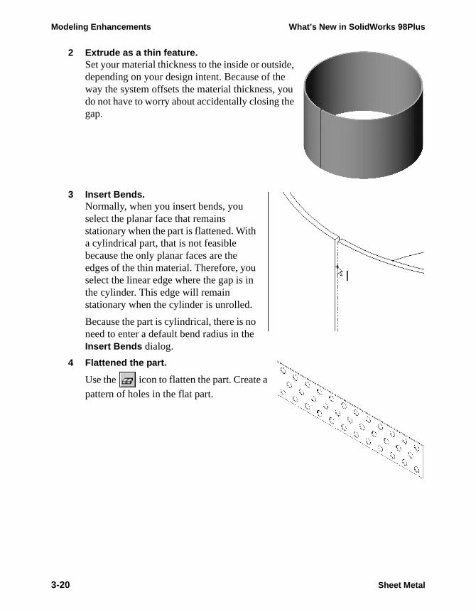
2 Extrude as a thin feature.Set your material thickness to the inside or outside, depending on your design intent. Because of the way the system offsets the material thickness, you do not have to worry about accidentally closing the gap.
3 Insert Bends.Normally, when you insert bends, you select the planar face that remains stationary when the part is flattened. With a cylindrical part, that is not feasible because the only planar faces are the edges of the thin material. Therefore, you select the linear edge where the gap is in the cylinder. This edge will remain stationary when the cylinder is unrolled.
Because the part is cylindrical, there is no need to enter a default bend radius in the Insert Bends dialog.
4 Flattened the part.
Use the icon to flatten the part. Create a
pattern of holes in the flat part.
3-20 Sheet Metal
What’s New in SolidWorks 98Plus Modeling Enhancements
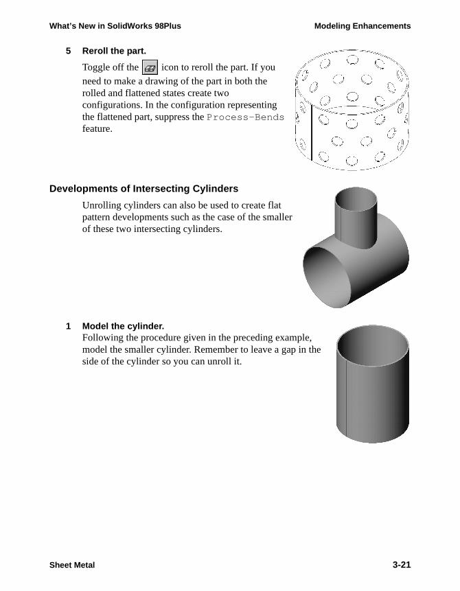
5 Reroll the part.
Toggle off the icon to reroll the part. If you
need to make a drawing of the part in both the rolled and flattened states create two configurations. In the configuration representing the flattened part, suppress the Process-Bends feature.
Developments of Intersecting Cylinders
Unrolling cylinders can also be used to create flat pattern developments such as the case of the smaller of these two intersecting cylinders.
1 Model the cylinder.Following the procedure given in the preceding example, model the smaller cylinder. Remember to leave a gap in the side of the cylinder so you can unroll it.
Sheet Metal 3-21
Modeling Enhancements What’s New in SolidWorks 98Plus
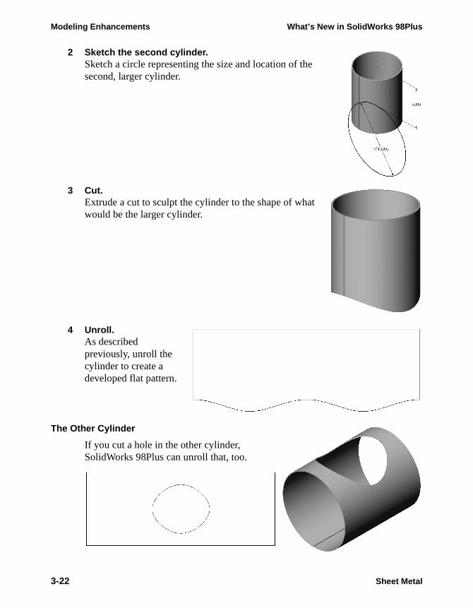
2 Sketch the second cylinder.Sketch a circle representing the size and location of the second, larger cylinder.
3 Cut.Extrude a cut to sculpt the cylinder to the shape of what would be the larger cylinder.
4 Unroll.As described previously, unroll the cylinder to create a developed flat pattern.
The Other Cylinder
If you cut a hole in the other cylinder, SolidWorks 98Plus can unroll that, too.
3-22 Sheet Metal
What’s New in SolidWorks 98Plus Modeling Enhancements
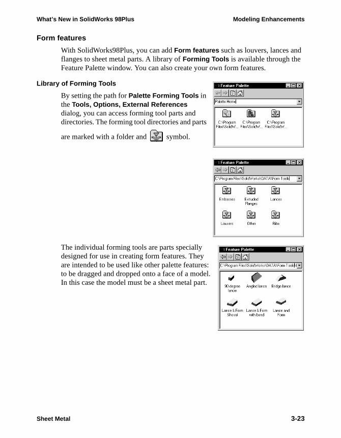
Form features
With SolidWorks98Plus, you can add Form features such as louvers, lances and flanges to sheet metal parts. A library of Forming Tools is available through the Feature Palette window. You can also create your own form features.
Library of Forming Tools
By setting the path for Palette Forming Tools in the Tools, Options, External References dialog, you can access forming tool parts and directories. The forming tool directories and parts
are marked with a folder and symbol.
The individual forming tools are parts specially designed for use in creating form features. They are intended to be used like other palette features: to be dragged and dropped onto a face of a model. In this case the model must be a sheet metal part.
Sheet Metal 3-23
Modeling Enhancements What’s New in SolidWorks 98Plus
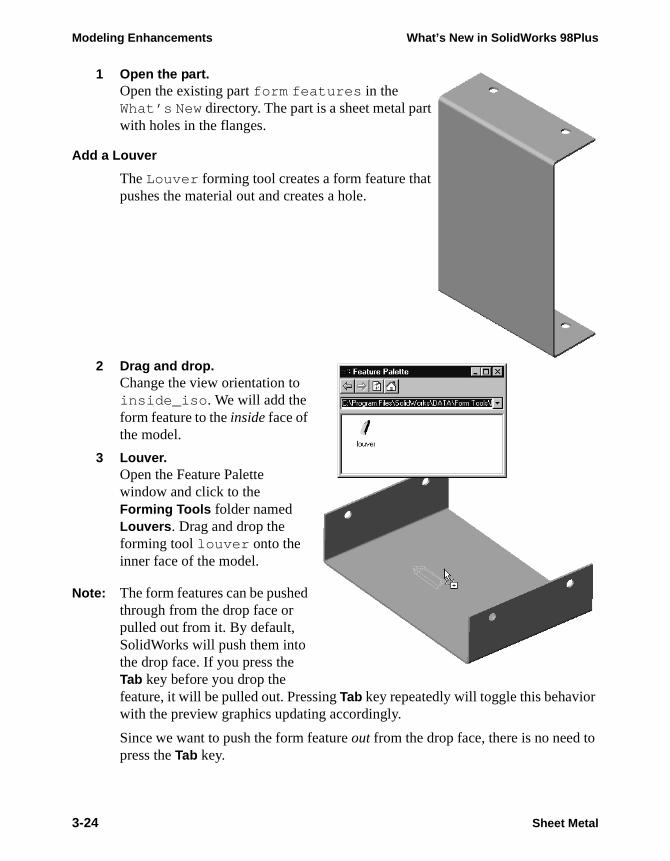
1 Open the part.Open the existing part form features in the What’s New directory. The part is a sheet metal part with holes in the flanges.
Add a Louver
The Louver forming tool creates a form feature that pushes the material out and creates a hole.
2 Drag and drop.Change the view orientation to inside_iso . We will add the form feature to the inside face of the model.
3 Louver.Open the Feature Palette window and click to the Forming Tools folder named Louvers. Drag and drop the forming tool louver onto the inner face of the model.
Note: The form features can be pushed through from the drop face or pulled out from it. By default, SolidWorks will push them into the drop face. If you press the Tab key before you drop the feature, it will be pulled out. Pressing Tab key repeatedly will toggle this behavior with the preview graphics updating accordingly.
Since we want to push the form feature out from the drop face, there is no need to press the Tab key.
3-24 Sheet Metal

What’s New in SolidWorks 98Plus Modeling Enhancements
4 Orient the sketch.Position the forming tool by adding dimensions or relations to the sketch.
Using Modify Sketch, rotate the sketch -90° to orient it properly.
5 Fully Define the sketch.Add a Collinear relation between the short centerline and the reference plane Plane3. Add a dimension as shown to fully define the sketch.
Sheet Metal 3-25

Modeling Enhancements What’s New in SolidWorks 98Plus
6 Click Finish.Click the Finish button to add the form feature to the model. The form feature appears in the feature manager with the name louver1.
The form feature can also be added in the flat state and will appear there. Simply roll back the model to before Process-Bends1 and add the feature.
Direction of the Forming Tool
When adding a feature like a louver, you have the option of dropping it on the inside or outside face. By default, the tool punches through the face on which it is dropped. However, by using the Tab key, you can reverse the default behavior. It determines whether the louver is punched in or out.
Dropped on outside face
Dropped on outside face with Tab key
Dropped on inside face
Dropped on inside face with Tab key
3-26 Sheet Metal
What’s New in SolidWorks 98Plus Modeling Enhancements
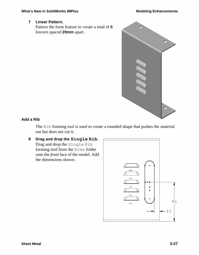
7 Linear Pattern.Pattern the form feature to create a total of 5 louvers spaced 20mm apart.
Add a Rib
The Rib forming tool is used to create a rounded shape that pushes the material out but does not cut it.
8 Drag and drop the Single Rib.Drag and drop the Single Rib forming tool from the Ribs folder onto the front face of the model. Add the dimensions shown.
Sheet Metal 3-27

Modeling Enhancements What’s New in SolidWorks 98Plus
9 Finished rib.Click the Finish button to add the feature. Change the size of the feature by double clicking on it and setting the 20mm rib width dimension to 10mm. Rebuild the model.
10 File the part.
Creating Your Own Forming Tools
You can create your own forming tools by following the methods used in creating the standard ones. Let’s look closely at a typical form feature part, the round flange, feature by feature.
1 Open the library part.Position the cursor over the round flange icon in the Feature Palette window and pick Edit Palette Item from the right-mouse menu. (It is the only choice.) This will open the corresponding library part in your SolidWorks window.
2 Rollback to Base-Extrude.The base feature of the form represents the sheet metal it will be attached to.
3-28 Sheet Metal
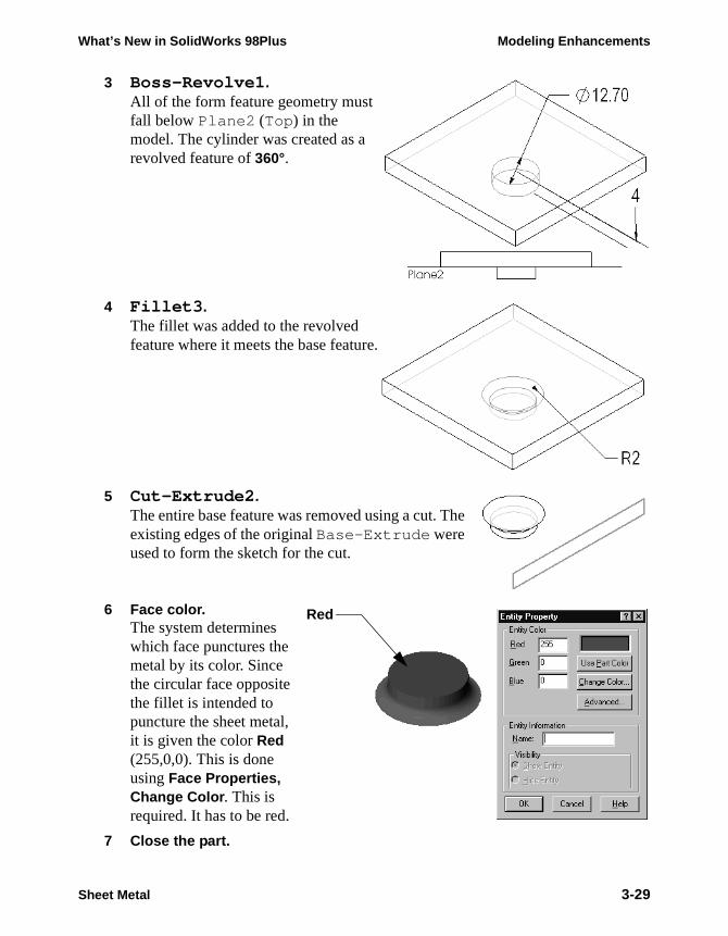
What’s New in SolidWorks 98Plus Modeling Enhancements
3 Boss-Revolve1.All of the form feature geometry must fall below Plane2 (Top) in the model. The cylinder was created as a revolved feature of 360°.
4 Fillet3.The fillet was added to the revolved feature where it meets the base feature.
5 Cut-Extrude2.The entire base feature was removed using a cut. The existing edges of the original Base-Extrude were used to form the sketch for the cut.
6 Face color.The system determines which face punctures the metal by its color. Since the circular face opposite the fillet is intended to puncture the sheet metal, it is given the color Red (255,0,0). This is done using Face Properties, Change Color . This is required. It has to be red.
7 Close the part.
Red
Sheet Metal 3-29
Modeling Enhancements What’s New in SolidWorks 98Plus
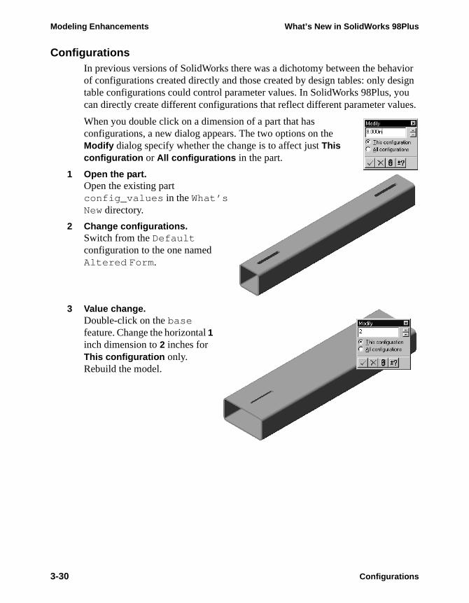
ConfigurationsIn previous versions of SolidWorks there was a dichotomy between the behavior of configurations created directly and those created by design tables: only design table configurations could control parameter values. In SolidWorks 98Plus, you can directly create different configurations that reflect different parameter values.
When you double click on a dimension of a part that has configurations, a new dialog appears. The two options on the Modify dialog specify whether the change is to affect just This configuration or All configurations in the part.
1 Open the part.Open the existing part config_values in the What’s New directory.
2 Change configurations.Switch from the Default configuration to the one named Altered Form.
3 Value change.Double-click on the base feature. Change the horizontal 1 inch dimension to 2 inches for This configuration only. Rebuild the model.
3-30 Configurations
What’s New in SolidWorks 98Plus Modeling Enhancements
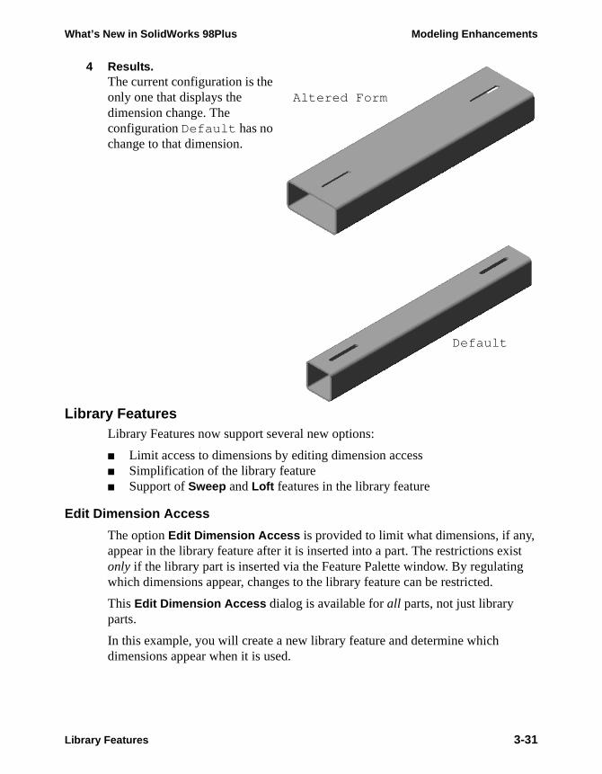
4 Results.The current configuration is the only one that displays the dimension change. The configuration Default has no change to that dimension.
Library FeaturesLibrary Features now support several new options:
■ Limit access to dimensions by editing dimension access■ Simplification of the library feature■ Support of Sweep and Loft features in the library feature
Edit Dimension Access
The option Edit Dimension Access is provided to limit what dimensions, if any, appear in the library feature after it is inserted into a part. The restrictions exist only if the library part is inserted via the Feature Palette window. By regulating which dimensions appear, changes to the library feature can be restricted.
This Edit Dimension Access dialog is available for all parts, not just library parts.
In this example, you will create a new library feature and determine which dimensions appear when it is used.
Altered Form
Default
non-printing
Library Features 3-31
Modeling Enhancements What’s New in SolidWorks 98Plus
is
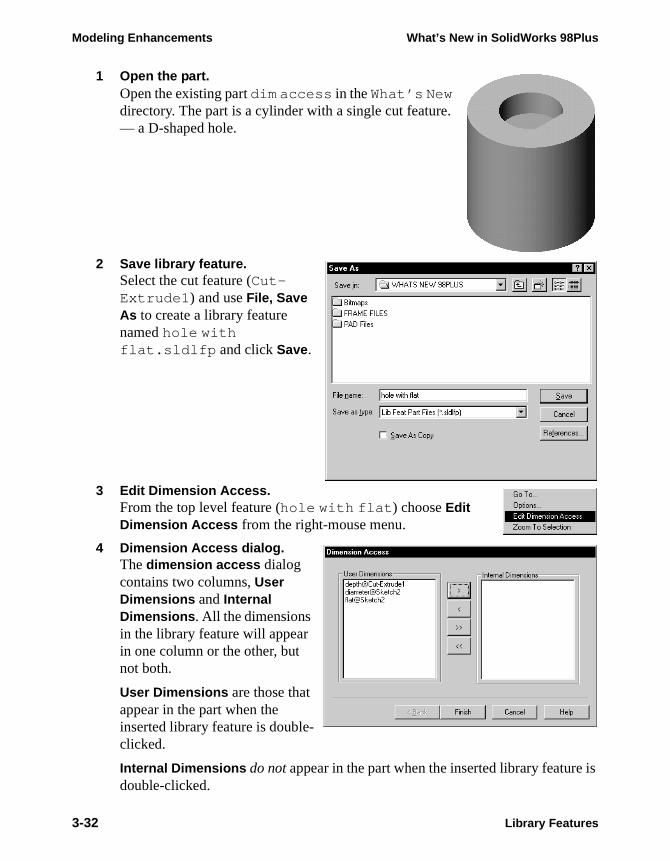
1 Open the part.Open the existing part dim access in the What’s New directory. The part is a cylinder with a single cut feature. — a D-shaped hole.
2 Save library feature.Select the cut feature (Cut-Extrude1) and use File, Save As to create a library feature named hole with flat.sldlfp and click Save.
3 Edit Dimension Access.From the top level feature (hole with flat) choose Edit Dimension Access from the right-mouse menu.
4 Dimension Access dialog.The dimension access dialog contains two columns, User Dimensions and Internal Dimensions. All the dimensions in the library feature will appear in one column or the other, but not both.
User Dimensions are those that appear in the part when the inserted library feature is double-clicked.
Internal Dimensions do not appear in the part when the inserted library featuredouble-clicked.
3-32 Library Features
What’s New in SolidWorks 98Plus Modeling Enhancements
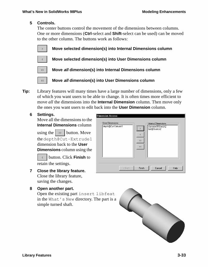
5 Controls.The center buttons control the movement of the dimensions between columns. One or more dimensions (Ctrl-select and Shift-select can be used) can be moved to the other column. The buttons work as follows:
Move selected dimension(s) into Internal Dimensions column
Move selected dimension(s) into User Dimensions column
Move all dimension(s) into Internal Dimensions column
Move all dimension(s) into User Dimensions column
Tip: Library features will many times have a large number of dimensions, only a few of which you want users to be able to change. It is often times more efficient to move all the dimensions into the Internal Dimension column. Then move only the ones you want users to edit back into the User Dimension column.
6 Settings.Move all the dimensions to the Internal Dimensions column
using the button. Move
the depth@Cut-Extrude1 dimension back to the User Dimensions column using the
button. Click Finish to
retain the settings.
7 Close the library feature.Close the library feature, saving the changes.
8 Open another part.Open the existing part insert libfeat in the What’s New directory. The part is a simple turned shaft.
Library Features 3-33

Modeling Enhancements What’s New in SolidWorks 98Plus
9 Insert Library Feature.Select the library feature hole with flat.sldlfp. Click Open.
10 Reference selections.For the Mandatory Reference Plane select the circular face of the model. For the Optional Reference Sketch Point select the Origin of the part from the FeatureManager design tree or graphics window.
Click OK to add the library feature.
Plane
Origin
3-34 Library Features
What’s New in SolidWorks 98Plus Modeling Enhancements
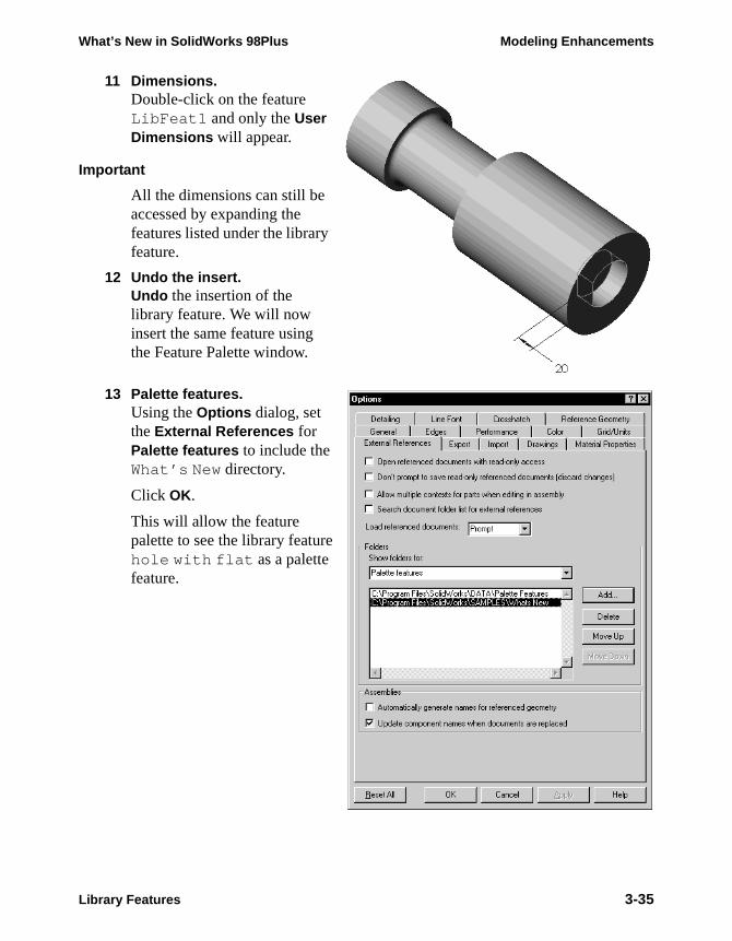
11 Dimensions.Double-click on the feature LibFeat1 and only the User Dimensions will appear.
Important
All the dimensions can still be accessed by expanding the features listed under the library feature.
12 Undo the insert.Undo the insertion of the library feature. We will now insert the same feature using the Feature Palette window.
13 Palette features.Using the Options dialog, set the External References for Palette features to include the What’s New directory.
Click OK.
This will allow the feature palette to see the library feature hole with flat as a palette feature.
Library Features 3-35
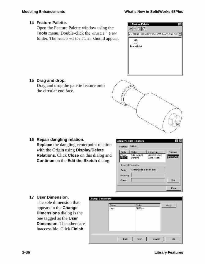
Modeling Enhancements What’s New in SolidWorks 98Plus
14 Feature Palette.Open the Feature Palette window using the Tools menu. Double-click the Whats’ New folder. The hole with flat should appear.
15 Drag and drop.Drag and drop the palette feature onto the circular end face.
16 Repair dangling relation.Replace the dangling centerpoint relation with the Origin using Display/Delete Relations. Click Close on this dialog and Continue on the Edit the Sketch dialog.
17 User Dimension.The sole dimension that appears in the Change Dimensions dialog is the one tagged as the User Dimension. The others are inaccessible. Click Finish.
3-36 Library Features

What’s New in SolidWorks 98Plus Modeling Enhancements
eep in uilt
18 Double-click the feature.Double-clicking on the copied palette feature shows that only the User Dimension is accessible.
19 Close the part.
Conclusion
As you can see from this example, you have better control over the user’s access to a library feature’s dimensions if it is inserted using the Feature Palette window rather than Insert Library Feature.
Simplification of Library Features
If you are working on a part and you have just finished making a feature that you would like to save as a library feature, you can do so. Select the feature(s) that you want to be included in the library feature and use File, Save As to make the library feature. When you do this, the system will prompt youasking if you want to simplify the library feature. If you click Yes, the system will remove all features except the base feature and the features you selected. Kmind that this might cause some rebuild errors in the library feature if it was bwith references to features the system deleted during simplification.
Consider the part shown at the right. The last features built were the mounting tab on the base and its fillet. To save this as a library fea-ture, select the boss and the fillet. The system will strip out all the other features in the part, leaving just the base feature, the extruded boss, and the fillet.
Library Features 3-37
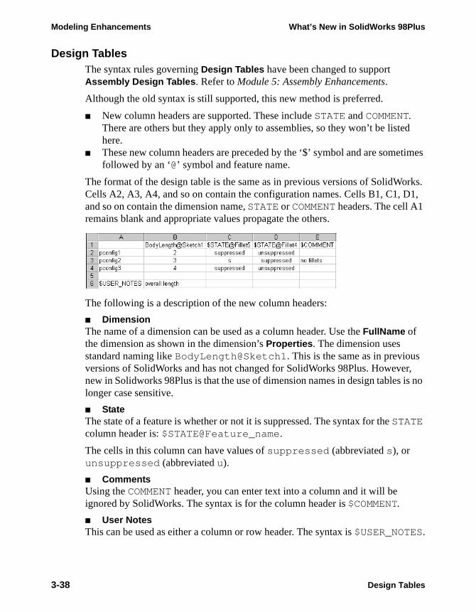
Modeling Enhancements What’s New in SolidWorks 98Plus
d
times
orks. 1,
r, is no
Design TablesThe syntax rules governing Design Tables have been changed to support Assembly Design Tables. Refer to Module 5: Assembly Enhancements.
Although the old syntax is still supported, this new method is preferred.
■ New column headers are supported. These include STATE and COMMENT. There are others but they apply only to assemblies, so they won’t be listehere.
■ These new column headers are preceded by the ‘$’ symbol and are somefollowed by an ‘@’ symbol and feature name.
The format of the design table is the same as in previous versions of SolidWCells A2, A3, A4, and so on contain the configuration names. Cells B1, C1, Dand so on contain the dimension name, STATE or COMMENT headers. The cell A1 remains blank and appropriate values propagate the others.
The following is a description of the new column headers:
■ DimensionThe name of a dimension can be used as a column header. Use the FullName of the dimension as shown in the dimension’s Properties. The dimension uses standard naming like BodyLength@Sketch1. This is the same as in previousversions of SolidWorks and has not changed for SolidWorks 98Plus. Howevenew in Solidworks 98Plus is that the use of dimension names in design tableslonger case sensitive.
■ StateThe state of a feature is whether or not it is suppressed. The syntax for the STATE column header is: $STATE@Feature_name.
The cells in this column can have values of suppressed (abbreviated s), or unsuppressed (abbreviated u).
■ CommentsUsing the COMMENT header, you can enter text into a column and it will be ignored by SolidWorks. The syntax is for the column header is $COMMENT.
■ User NotesThis can be used as either a column or row header. The syntax is $USER_NOTES.
3-38 Design Tables
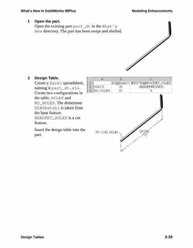
What’s New in SolidWorks 98Plus Modeling Enhancements
1 Open the part.Open the existing part part_dt in the What’s New directory. The part has been swept and shelled.
2 Design Table.Create a Excel spreadsheet, naming it part_dt.xls . Create two configurations in the table, HOLES and NO_HOLES. The dimension D2@Sketch1 is taken from the base feature. BRACKET_HOLES is a cut feature.
Insert the design table into the part.
Design Tables 3-39
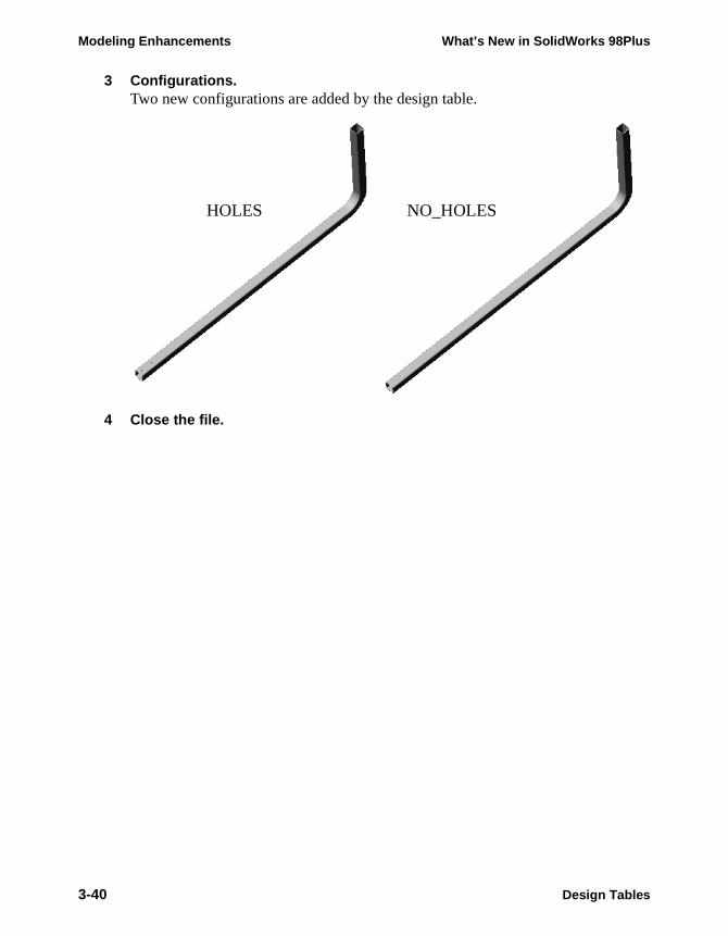
Modeling Enhancements What’s New in SolidWorks 98Plus
3 Configurations.Two new configurations are added by the design table.
4 Close the file.
HOLES NO_HOLES
3-40 Design Tables

What’s New in SolidWorks 98Plus
Module 4Drawing Enhancements


What’s New in SolidWorks 98Plus Drawing Enhancements
Importing Model DimensionsNow you can import model dimensions into all views of the drawing at once. The dialog option Import Dimensions Into All Views must be checked.
SolidWorks adds dimensions to section and detail views first, then to standard views.
Detail and Section ViewsNow Detail and Section views can be cut and pasted to another sheet within a drawing. Use Edit, Cut and Edit, Paste, the cut and paste icons, CTRL+X and CTRL+V, or drag and drop the view from one FeatureManager window to the other.
You can also copy and paste section and detail views to other drawings. However, these will only paste if their parent view is on the new drawing as well. For example, assume that on Draw1 you have a Front view and a section view of it. If you copy the Front view and paste it onto Draw2, you can then copy the section view to Draw2 as well. In fact, you can copy both views at the same time if you want to.
Auto Hatching of Section ViewsIn SolidWorks 98Plus, assemblies that are sectioned can have Auto Hatching to vary the cross hatching between adjacent components in the assembly.
When the assembly is sectioned, the Section Scope dialog appears with a new option, Auto Hatching, checked by default.
Importing Model Dimensions 4-1
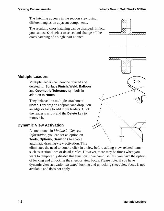
Drawing Enhancements What’s New in SolidWorks 98Plus
s u tion
t
The hatching appears in the section view using different angles on adjacent components.
The resulting cross hatching can be changed. In fact, you can use Ctrl-select to select and change all the cross hatching of a single part at once.
Multiple LeadersMultiple leaders can now be created and deleted for Surface Finish, Weld, Balloon and Geometric Tolerance symbols in addition to Notes.
They behave like multiple attachment Notes. Ctrl-drag an endpoint and drop it on an edge or face to add more leaders. Click the leader’s arrow and the Delete key to remove it.
Dynamic View ActivationAs mentioned in Module 2: General Information, you can set an option on Tools, Options, Drawings to enable automatic drawing view activation. This eliminates the need to double-click in a view before adding view-related itemsuch as section lines or detail circles. However, there may be times when yowant to temporarily disable this function. To accomplish this, you have the opof locking and unlocking the sheet or view focus. Please note: if you have dynamic view activation disabled, locking and unlocking sheet/view focus is noavailable and does not apply.
4-2 Multiple Leaders
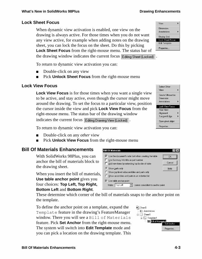
What’s New in SolidWorks 98Plus Drawing Enhancements
Lock Sheet Focus
When dynamic view activation is enabled, one view on the drawing is always active. For those times when you do not want any view active, for example when adding notes on the drawing sheet, you can lock the focus on the sheet. Do this by picking Lock Sheet Focus from the right-mouse menu. The status bar of the drawing window indicates the current focus .
To return to dynamic view activation you can:
■ Double-click on any view■ Pick Unlock Sheet Focus from the right-mouse menu
Lock View Focus
Lock View Focus is for those times when you want a single view to be active, and stay active, even though the cursor might move around the drawing. To set the focus to a particular view, position the cursor inside the view and pick Lock View Focus from the right-mouse menu. The status bar of the drawing window indicates the current focus .
To return to dynamic view activation you can:
■ Double-click on any other view■ Pick Unlock View Focus from the right-mouse menu
Bill Of Materials EnhancementsWith SolidWorks 98Plus, you can anchor the bill of materials block to the drawing sheet.
When you insert the bill of materials, Use table anchor point gives you four choices: Top Left, Top Right, Bottom Left and Bottom Right. These determine which corner of the bill of materials snaps to the anchor point on the template.
To define the anchor point on a template, expand the Template feature in the drawing’s FeatureManager window. There you will see a Bill of Materials feature. Pick Set Anchor from the right-mouse menu. The system will switch into Edit Template mode and you can pick a location on the drawing template. This
Bill Of Materials Enhancements 4-3

Drawing Enhancements What’s New in SolidWorks 98Plus
location will become the anchor point used by the bill of materials when it is inserted. This anchor point can be saved in the template using Save Template.
If the BOM is set to Use the document’s note font when creating the table , changes to the Note Font setting will bring about this message. Click Yes to have SolidWorks resize the BOM to the new text size.
You can manually add items to the bill of materials. This enables you to list items that do not require components in the assembly. Examples of such items include oil, paint, safety wires, and thread sealant. This also enables you to include standard fasteners without having to include every nut, bolt, and washer in the assembly.
To add items to the BOM, double-click on the bill of materials. This will start Excel. Select the row containing the keyword $END. Using the Excel command Insert, Rows , add as many new rows as you will need. You can then type the information you want into the cells.
Drag Multiple ViewsNow multiple drawing views can be dragged simultaneously on the drawing sheet. On the screen, use Ctrl -select to identify them. In the FeatureManager design tree, use either Ctrl - or Shift - select. Drag one of the views by the visible edge and they will all move.
Broken View EnhancementsBroken views have been enhanced so that they can show:
■ Sections lines and detail geometry■ Temporary axes■ Cosmetic threads
Cosmetic Thread EnhancementsCosmetic Threads have new behavior in drawings.
■ In section views hidden cosmetic threads will no longer be displayed■ Dimensions of cosmetic threads can be imported into drawing views■ Thread display is copied with the view
4-4 Drag Multiple Views
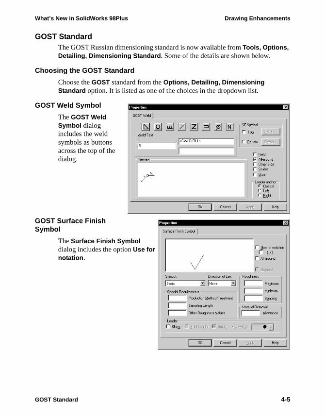
What’s New in SolidWorks 98Plus Drawing Enhancements
GOST StandardThe GOST Russian dimensioning standard is now available from Tools, Options, Detailing, Dimensioning Standard. Some of the details are shown below.
Choosing the GOST Standard
Choose the GOST standard from the Options, Detailing, Dimensioning Standard option. It is listed as one of the choices in the dropdown list.
GOST Weld Symbol
The GOST Weld Symbol dialog includes the weld symbols as buttons across the top of the dialog.
GOST Surface Finish Symbol
The Surface Finish Symbol dialog includes the option Use for notation.
GOST Standard 4-5

Drawing Enhancements What’s New in SolidWorks 98Plus
Section and Detail Views
The GOST standard for section and detail views is shown here. In the parent view, the Section Line A-A and Detail Views I and II are shown.
The Section arrows are offset from the ends of the section line by 3mm. The Detail circles include leaders to the text and an underlined roman numeral as an identifier. The text can be dragged.
The Section View shows the name, A-A, underlined and above the section view.
The Detail View displays the section name underlined with the scale listed below.
Geometric Tolerance Enhancements
Geometric Tolerance frames attached to dimensions can now be moved outside the witness lines. A leader extends to the frame through the dimension.
4-6 Geometric Tolerance Enhancements
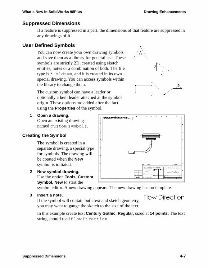
What’s New in SolidWorks 98Plus Drawing Enhancements
Suppressed DimensionsIf a feature is suppressed in a part, the dimensions of that feature are suppressed in any drawings of it.
User Defined SymbolsYou can now create your own drawing symbols and save them as a library for general use. These symbols are strictly 2D, created using sketch entities, notes or a combination of both. The file type is *.sldsym, and it is created in its own special drawing. You can access symbols within the library to change them.
The custom symbol can have a leader or optionally a bent leader attached at the symbol origin. These options are added after the fact using the Properties of the symbol.
1 Open a drawing.Open an existing drawing named custom symbols.
Creating the Symbol
The symbol is created in a separate drawing, a special type for symbols. The drawing will be created when the New symbol is initiated.
2 New symbol drawing.Use the option Tools, Custom Symbol, New to start the symbol editor. A new drawing appears. The new drawing has no template.
3 Insert a note.If the symbol will contain both text and sketch geometry, you may want to gauge the sketch to the size of the text.
In this example create text Century Gothic, Regular, sized at 14 points. The text string should read Flow Direction.
Suppressed Dimensions 4-7

Drawing Enhancements What’s New in SolidWorks 98Plus
4 Sketch an arrow.Using lines, sketch an arrow as shown.
Use Equal and Collinear relations to shape the arrow properly.
Note that dimensions and crosshatching will not appear in the finished symbol but construction geometry will.
5 Save the symbol.Click the Save option and name the symbol flow arrow symbol. The extension *.sldsym is added automatically. Click Save.
6 Saved symbol.The symbol has now been saved to the library. It is a single piece of geometry with an attachment point at the left lower corner of the enclosing box.
Tip: Zoom in tightly on the symbol before you save the file. It will give you a better looking bitmap image for the preview graphics when you go to insert the symbol.
7 Close the drawing.Close the symbol drawing, saving it.
4-8 User Defined Symbols
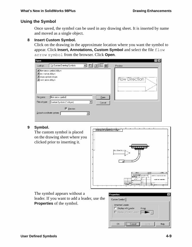
What’s New in SolidWorks 98Plus Drawing Enhancements
Using the Symbol
Once saved, the symbol can be used in any drawing sheet. It is inserted by name and moved as a single object.
8 Insert Custom Symbol.Click on the drawing in the approximate location where you want the symbol to appear. Click Insert, Annotations, Custom Symbol and select the file flow arrow symbol from the browser. Click Open.
9 Symbol.The custom symbol is placed on the drawing sheet where you clicked prior to inserting it.
The symbol appears without a leader. If you want to add a leader, use the Properties of the symbol.
User Defined Symbols 4-9
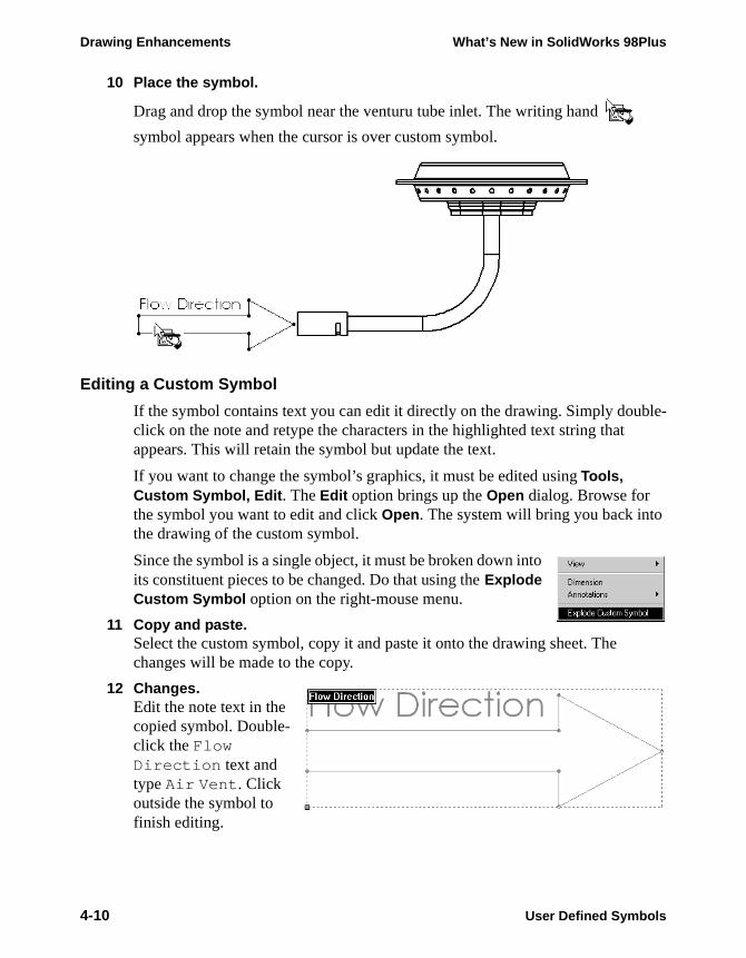
Drawing Enhancements What’s New in SolidWorks 98Plus
10 Place the symbol.
Drag and drop the symbol near the venturu tube inlet. The writing hand
symbol appears when the cursor is over custom symbol.
Editing a Custom Symbol
If the symbol contains text you can edit it directly on the drawing. Simply double-click on the note and retype the characters in the highlighted text string that appears. This will retain the symbol but update the text.
If you want to change the symbol’s graphics, it must be edited using Tools, Custom Symbol, Edit. The Edit option brings up the Open dialog. Browse for the symbol you want to edit and click Open. The system will bring you back intothe drawing of the custom symbol.
Since the symbol is a single object, it must be broken down into its constituent pieces to be changed. Do that using the Explode Custom Symbol option on the right-mouse menu.
11 Copy and paste.Select the custom symbol, copy it and paste it onto the drawing sheet. The changes will be made to the copy.
12 Changes.Edit the note text in the copied symbol. Double-click the Flow Direction text and type Air Vent. Click outside the symbol to finish editing.
4-10 User Defined Symbols
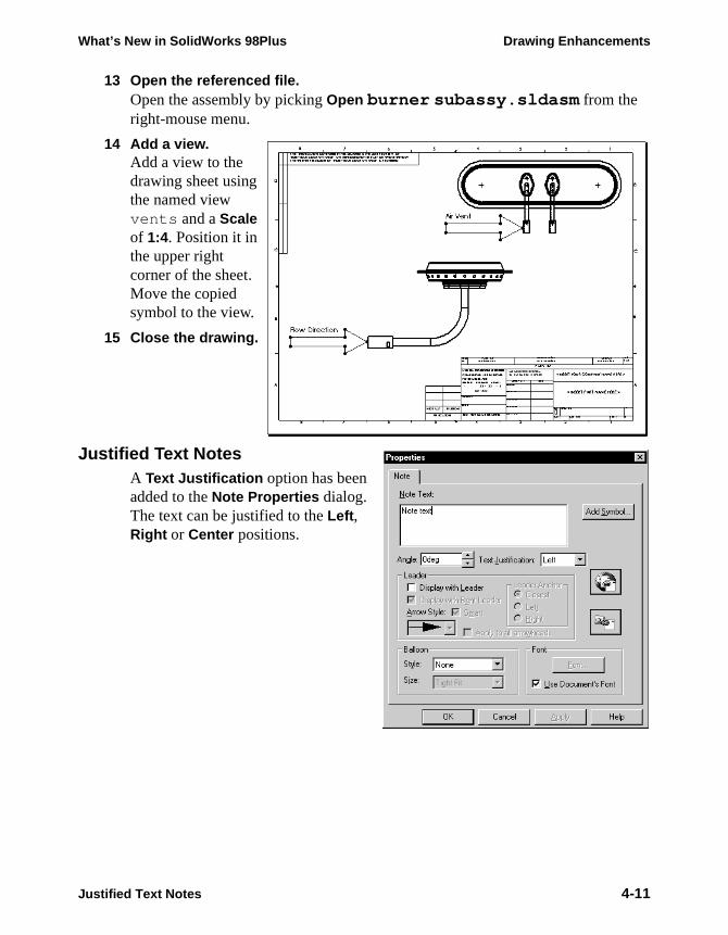
What’s New in SolidWorks 98Plus Drawing Enhancements
13 Open the referenced file.Open the assembly by picking Open burner subassy.sldasm from the right-mouse menu.
14 Add a view.Add a view to the drawing sheet using the named view vents and a Scale of 1:4. Position it in the upper right corner of the sheet. Move the copied symbol to the view.
15 Close the drawing.
Justified Text NotesA Text Justification option has been added to the Note Properties dialog. The text can be justified to the Left, Right or Center positions.
Justified Text Notes 4-11

Drawing Enhancements What’s New in SolidWorks 98Plus
iews eet, et.
ing’s
t
Document PropertiesSolidWorks 98Plus has expanded the basic system Properties available in a drawing.
Properties
The Properties can be used with notes and the Link to Property option. They are described below.
■ SW-File NameThe SolidWorks part/assembly/drawing name (without the file extension) is output into the note. See External model reference below.
■ SW-Template SizeOutputs the sheet or template size (A, C, A2, etc.).
■ SW-Sheet ScaleThe sheet scale of the attached view is output.
■ SW-Current SheetListed as an integer value (1, 2, 3...) in order.
■ SW-Total SheetsAn integer indicating the total number of sheets in the drawing file.
■ SW-Sheet NameThe name of the sheet as you create it.
Using these properties, you can create drawing notes such as “Sheet 1 of 5” where the “1” and “5” are read from the drawing file itself. The note will update if the number of sheets changes.
The External model reference checkbox has a different effect depending on whether a note is attached to the view or a drawing. A drawing can contain vof different parts and/or assemblies. If the note is attached to the drawing shExternal model reference causes it to use the first reference in the drawing sheThat is, the part or assembly referenced by the first view as listed in the drawFeatureManager tree.
If the note is attached to the drawing sheet and External model reference is not checked, it uses the drawing file name.
If the note is attached to a view, it uses the name of the file referenced by thaview.
4-12 Document Properties

What’s New in SolidWorks 98Plus Drawing Enhancements
Multiple References
For situations when more than one part/assembly is displayed on one sheet, the Sheet Setup dialog provides some options. The pulldown beneath Use custom property values from model shown in has the values Default, Drawing View 1, Drawing View 2 and so on. This allows you to choose the source of the properties used.
1 Open a new drawing.Open a new drawing, B-Landscape, using the standard template.
2 Open a part.Open the existing part Pivot located in the What’s New directory.
3 ViewsCreate the standard three views of the Pivot part in the new drawing.
4 Edit the drawing template.Using Edit Template, go to the drawing template. If you haven’t already, delete the standard note in the center of the sheet. Zoom in on the title block area.
Document Properties 4-13
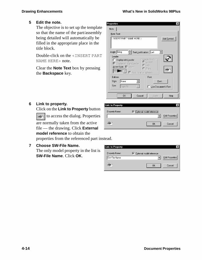
Drawing Enhancements What’s New in SolidWorks 98Plus
5 Edit the note.The objective is to set up the template so that the name of the part/assembly being detailed will automatically be filled in the appropriate place in the title block.
Double-click on the <INSERT PART NAME HERE> note.
Clear the Note Text box by pressing the Backspace key.
6 Link to property.Click on the Link to Property button
to access the dialog. Properties
are normally taken from the active file — the drawing. Click External model reference to obtain the properties from the referenced part instead.
7 Choose SW-File Name.The only model property in the list is SW-File Name. Click OK.
4-14 Document Properties
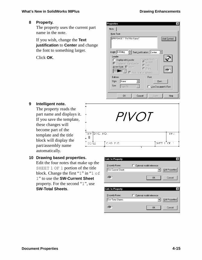
What’s New in SolidWorks 98Plus Drawing Enhancements
8 Property.The property uses the current part name in the note.
If you wish, change the Text justification to Center and change the font to something larger.
Click OK.
9 Intelligent note.The property reads the part name and displays it. If you save the template, these changes will become part of the template and the title block will display the part/assembly name automatically.
10 Drawing based properties.Edit the four notes that make up the SHEET 1 OF 1 portion of the title block. Change the first “1” in “1 of 1” to use the SW-Current Sheet property. For the second “1”, use SW-Total Sheets.
Document Properties 4-15
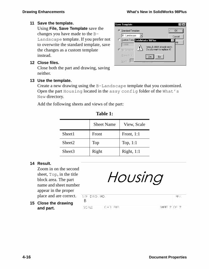
Drawing Enhancements What’s New in SolidWorks 98Plus
11 Save the template.Using File, Save Template save the changes you have made to the B-Landscape template. If you prefer not to overwrite the standard template, save the changes as a custom template instead.
12 Close files.Close both the part and drawing, saving neither.
13 Use the template.Create a new drawing using the B-Landscape template that you customized. Open the part Housing located in the assy config folder of the What’s New directory.
Add the following sheets and views of the part:
14 Result.Zoom in on the second sheet, Top , in the title block area. The part name and sheet number appear in the proper place and are correct.
15 Close the drawing and part.
Table 1:
Sheet Name View, Scale
Sheet1 Front Front, 1:1
Sheet2 Top Top, 1:1
Sheet3 Right Right, 1:1
4-16 Document Properties

What’s New in SolidWorks 98Plus
Module 5Assembly Enhancements

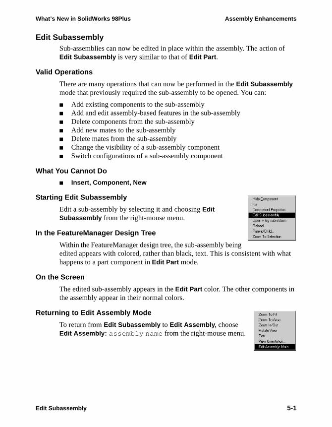
What’s New in SolidWorks 98Plus Assembly Enhancements
Edit SubassemblySub-assemblies can now be edited in place within the assembly. The action of Edit Subassembly is very similar to that of Edit Part.
Valid Operations
There are many operations that can now be performed in the Edit Subassembly mode that previously required the sub-assembly to be opened. You can:
■ Add existing components to the sub-assembly■ Add and edit assembly-based features in the sub-assembly■ Delete components from the sub-assembly■ Add new mates to the sub-assembly■ Delete mates from the sub-assembly■ Change the visibility of a sub-assembly component■ Switch configurations of a sub-assembly component
What You Cannot Do
■ Insert, Component, New
Starting Edit Subassembly
Edit a sub-assembly by selecting it and choosing Edit Subassembly from the right-mouse menu.
In the FeatureManager Design Tree
Within the FeatureManager design tree, the sub-assembly being edited appears with colored, rather than black, text. This is consistent with what happens to a part component in Edit Part mode.
On the Screen
The edited sub-assembly appears in the Edit Part color. The other components in the assembly appear in their normal colors.
Returning to Edit Assembly Mode
To return from Edit Subassembly to Edit Assembly, choose Edit Assembly: assembly name from the right-mouse menu.
Edit Subassembly 5-1
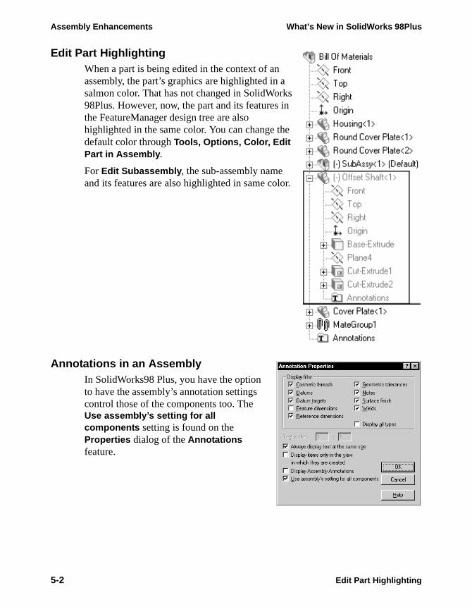
Assembly Enhancements What’s New in SolidWorks 98Plus
Edit Part HighlightingWhen a part is being edited in the context of an assembly, the part’s graphics are highlighted in a salmon color. That has not changed in SolidWorks 98Plus. However, now, the part and its features in the FeatureManager design tree are also highlighted in the same color. You can change the default color through Tools, Options, Color, Edit Part in Assembly.
For Edit Subassembly, the sub-assembly name and its features are also highlighted in same color.
Annotations in an AssemblyIn SolidWorks98 Plus, you have the option to have the assembly’s annotation settings control those of the components too. The Use assembly’s setting for all components setting is found on the Properties dialog of the Annotations feature.
5-2 Edit Part Highlighting
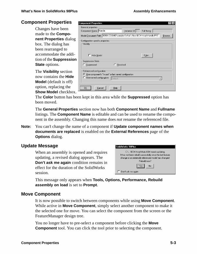
What’s New in SolidWorks 98Plus Assembly Enhancements
Component PropertiesChanges have been made to the Compo-nent Properties dialog box. The dialog has been rearranged to accommodate the addi-tion of the Suppression State options.
The Visibility section now contains the Hide Model (default is off) option, replacing the Show Model checkbox. The Color button has been kept in this area while the Suppressed option has been moved.
The General Properties section now has both Component Name and Fullname listings. The Component Name is editable and can be used to rename the compo-nent in the assembly. Changing this name does not rename the referenced file.
Note: You can’t change the name of a component if Update component names when documents are replaced is enabled on the External References page of the Options dialog.
Update MessageWhen an assembly is opened and requires updating, a revised dialog appears. The Don’t ask me again condition remains in effect for the duration of the SolidWorks session.
This message only appears when Tools, Options, Performance, Rebuild assembly on load is set to Prompt .
Move ComponentIt is now possible to switch between components while using Move Component . While active in Move Component , simply select another component to make it the selected one for move. You can select the component from the screen or the FeatureManager design tree.
You no longer have to pre-select a component before clicking the Move Component tool. You can click the tool prior to selecting the component.
Component Properties 5-3
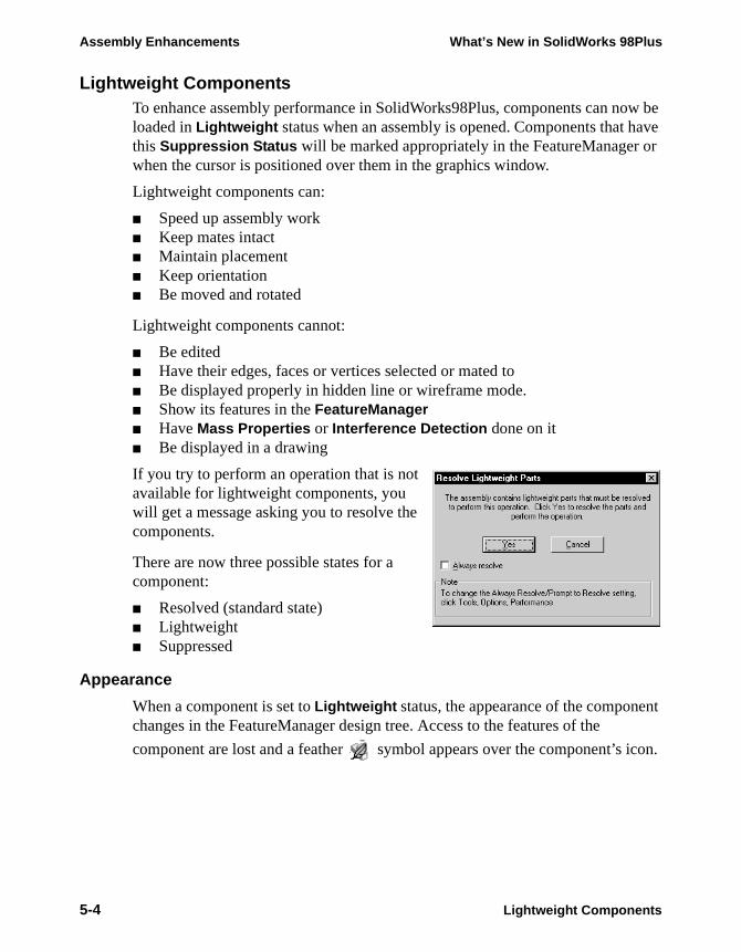
Assembly Enhancements What’s New in SolidWorks 98Plus
icon.
Lightweight ComponentsTo enhance assembly performance in SolidWorks98Plus, components can now be loaded in Lightweight status when an assembly is opened. Components that have this Suppression Status will be marked appropriately in the FeatureManager or when the cursor is positioned over them in the graphics window.
Lightweight components can:
■ Speed up assembly work■ Keep mates intact■ Maintain placement■ Keep orientation■ Be moved and rotated
Lightweight components cannot:
■ Be edited■ Have their edges, faces or vertices selected or mated to■ Be displayed properly in hidden line or wireframe mode.■ Show its features in the FeatureManager■ Have Mass Properties or Interference Detection done on it■ Be displayed in a drawing
If you try to perform an operation that is not available for lightweight components, you will get a message asking you to resolve the components.
There are now three possible states for a component:
■ Resolved (standard state)■ Lightweight■ Suppressed
Appearance
When a component is set to Lightweight status, the appearance of the component changes in the FeatureManager design tree. Access to the features of the
component are lost and a feather symbol appears over the component’s
5-4 Lightweight Components
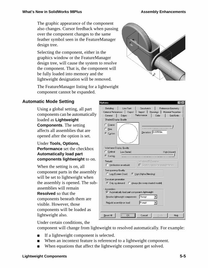
What’s New in SolidWorks 98Plus Assembly Enhancements
The graphic appearance of the component also changes. Cursor feedback when passing over the component changes to the same feather symbol seen in the FeatureManager design tree.
Selecting the component, either in the graphics window or the FeatureManager design tree, will cause the system to resolve the component. That is, the component will be fully loaded into memory and the lightweight designation will be removed.
The FeatureManager listing for a lightweight component cannot be expanded.
Automatic Mode Setting
Using a global setting, all part components can be automatically loaded as Lightweight Components. The setting affects all assemblies that are opened after the option is set.
Under Tools, Options, Performance set the checkbox Automatically load part components lightweight to on.
When the setting is on, all component parts in the assembly will be set to lightweight when the assembly is opened. The sub-assemblies will remain Resolved so that the components beneath them are visible. However, those components will be loaded as lightweight also.
Under certain conditions, the component will change from lightweight to resolved automatically. For example:
■ If a lightweight component is selected.■ When an incontext feature is referenced to a lightweight component.■ When equations that affect the lightweight component get solved.
Lightweight Components 5-5

Assembly Enhancements What’s New in SolidWorks 98Plus
Changing the Suppression Status
The Component Properties dialog has been modified to add the Suppression State option. This option consists of two mutually exclusive buttons which set the state of the component. The component can be a part or a sub-assembly.
The same options Suppress and Resolve, exist on the Assembly Toolbar. After selection of one or more components, click on the Change Suppression State icon and choose a state from the pulldown menu that appears.
Assembly FeatureManagerHighlighting of components in an assembly has changed. Select a top-level component, and the component icon highlights. Select a component of a sub-assembly and the sub-assembly icon highlights. If the option Scroll Selected Item Into View is toggled on, the highlighted icon will also be scrolled into view.
5-6 Changing the Suppression Status
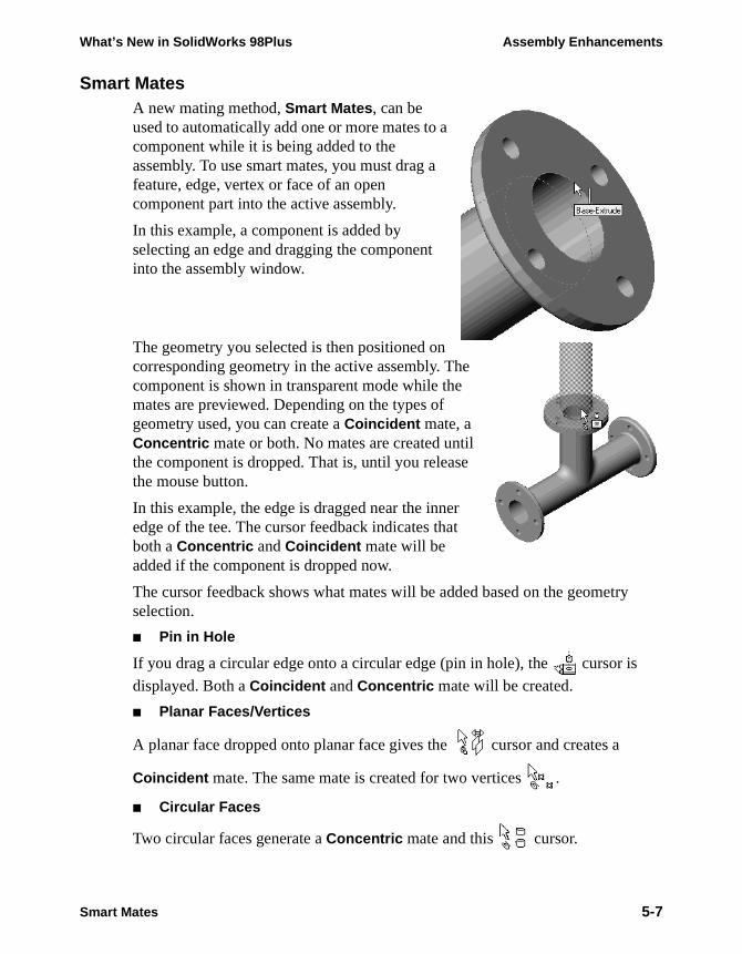
What’s New in SolidWorks 98Plus Assembly Enhancements
Smart MatesA new mating method, Smart Mates, can be used to automatically add one or more mates to a component while it is being added to the assembly. To use smart mates, you must drag a feature, edge, vertex or face of an open component part into the active assembly.
In this example, a component is added by selecting an edge and dragging the component into the assembly window.
The geometry you selected is then positioned on corresponding geometry in the active assembly. The component is shown in transparent mode while the mates are previewed. Depending on the types of geometry used, you can create a Coincident mate, a Concentric mate or both. No mates are created until the component is dropped. That is, until you release the mouse button.
In this example, the edge is dragged near the inner edge of the tee. The cursor feedback indicates that both a Concentric and Coincident mate will be added if the component is dropped now.
The cursor feedback shows what mates will be added based on the geometry selection.
■ Pin in Hole
If you drag a circular edge onto a circular edge (pin in hole), the cursor is
displayed. Both a Coincident and Concentric mate will be created.
■ Planar Faces/Vertices
A planar face dropped onto planar face gives the cursor and creates a
Coincident mate. The same mate is created for two vertices .
■ Circular Faces
Two circular faces generate a Concentric mate and this cursor.
Smart Mates 5-7
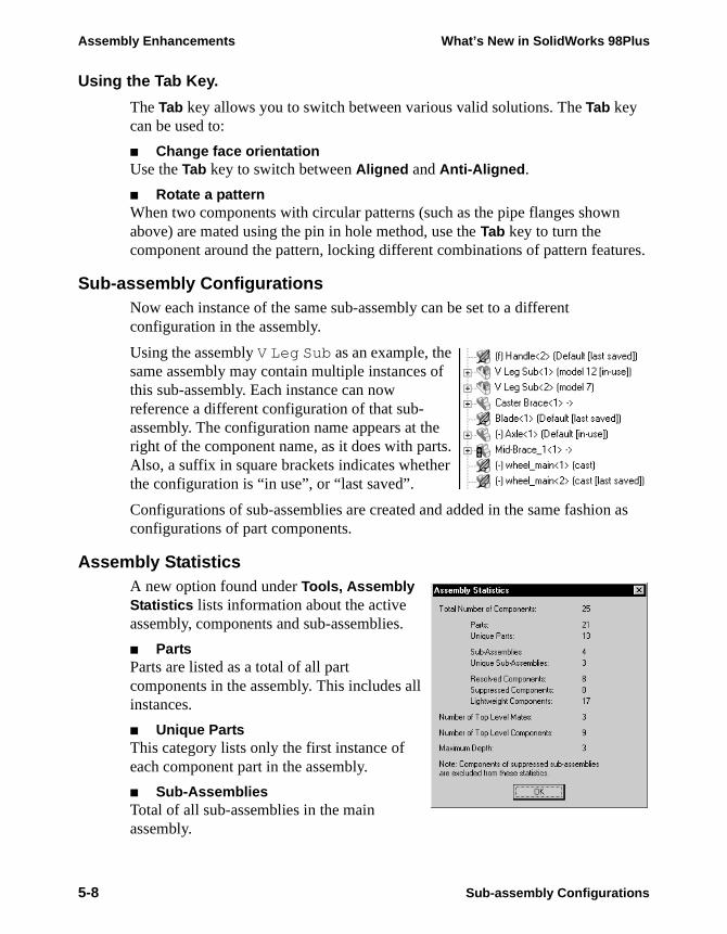
Assembly Enhancements What’s New in SolidWorks 98Plus
as
Using the Tab Key.
The Tab key allows you to switch between various valid solutions. The Tab key can be used to:
■ Change face orientationUse the Tab key to switch between Aligned and Anti-Aligned.
■ Rotate a patternWhen two components with circular patterns (such as the pipe flanges shown above) are mated using the pin in hole method, use the Tab key to turn the component around the pattern, locking different combinations of pattern features.
Sub-assembly ConfigurationsNow each instance of the same sub-assembly can be set to a different configuration in the assembly.
Using the assembly V Leg Sub as an example, the same assembly may contain multiple instances of this sub-assembly. Each instance can now reference a different configuration of that sub-assembly. The configuration name appears at the right of the component name, as it does with parts. Also, a suffix in square brackets indicates whether the configuration is “in use”, or “last saved”.
Configurations of sub-assemblies are created and added in the same fashionconfigurations of part components.
Assembly StatisticsA new option found under Tools, Assembly Statistics lists information about the active assembly, components and sub-assemblies.
■ PartsParts are listed as a total of all part components in the assembly. This includes all instances.
■ Unique PartsThis category lists only the first instance of each component part in the assembly.
■ Sub-AssembliesTotal of all sub-assemblies in the main assembly.
5-8 Sub-assembly Configurations

What’s New in SolidWorks 98Plus Assembly Enhancements
zed
■ Unique Sub-AssembliesFirst instance of each sub-assembly only.
■ Number of Top Level MatesMates in the active assembly, not counting those in any sub-assemblies.
■ Number of Top Level ComponentsComponents listed in the FeatureManager, both parts and sub-assemblies. Does not count any components under the sub-assemblies.
■ Maximum DepthDepth of nesting levels.
Part and Sub-assembly Configurations in an AssemblyComponent parts and sub-assemblies which are in configurations other than the last-saved configuration are now fully displayed and accessible. Each instance has the “+” sign, giving access to all their embedded features.
Drag and Drop Configurations
Now when you drag and drop a part or assembly with configurations into an assembly from Win-dows Explorer, you can choose the configuration to use.
Simply select the desired configuration from the Select a Configuration dialog, and click OK. The last saved configuration is highlighted in the list.
Assembly ConfigurationsIn SolidWorks 98Plus, more objects can be controlled by a configuration. Nowyou can control the following aspects of an assembly and have them recognithem as unique to a specific configuration:
■ Assembly Features■ Component Colors■ Component Patterns■ Cosmetic Threads■ Dimensions■ Mates■ Sketches■ Suppression Status
Part and Sub-assembly Configurations in an Assembly 5-9
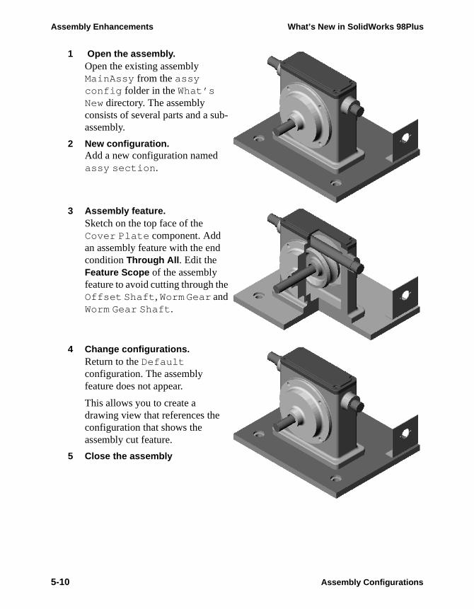
Assembly Enhancements What’s New in SolidWorks 98Plus
1 Open the assembly.Open the existing assembly MainAssy from the assy config folder in the What’s New directory. The assembly consists of several parts and a sub-assembly.
2 New configuration.Add a new configuration named assy section .
3 Assembly feature.Sketch on the top face of the Cover Plate component. Add an assembly feature with the end condition Through All. Edit the Feature Scope of the assembly feature to avoid cutting through the Offset Shaft , Worm Gear and Worm Gear Shaft .
4 Change configurations.Return to the Default configuration. The assembly feature does not appear.
This allows you to create a drawing view that references the configuration that shows the assembly cut feature.
5 Close the assembly
5-10 Assembly Configurations
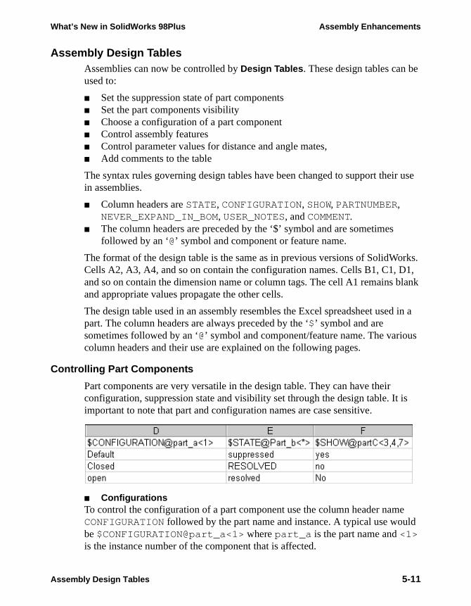
What’s New in SolidWorks 98Plus Assembly Enhancements
orks. 1, lank
d in a
s
is
e ld
Assembly Design TablesAssemblies can now be controlled by Design Tables. These design tables can be used to:
■ Set the suppression state of part components■ Set the part components visibility■ Choose a configuration of a part component■ Control assembly features■ Control parameter values for distance and angle mates,■ Add comments to the table
The syntax rules governing design tables have been changed to support their use in assemblies.
■ Column headers are STATE, CONFIGURATION, SHOW, PARTNUMBER, NEVER_EXPAND_IN_BOM, USER_NOTES, and COMMENT.
■ The column headers are preceded by the ‘$’ symbol and are sometimes followed by an ‘@’ symbol and component or feature name.
The format of the design table is the same as in previous versions of SolidWCells A2, A3, A4, and so on contain the configuration names. Cells B1, C1, Dand so on contain the dimension name or column tags. The cell A1 remains band appropriate values propagate the other cells.
The design table used in an assembly resembles the Excel spreadsheet usepart. The column headers are always preceded by the ‘$’ symbol and are sometimes followed by an ‘@’ symbol and component/feature name. The varioucolumn headers and their use are explained on the following pages.
Controlling Part Components
Part components are very versatile in the design table. They can have their configuration, suppression state and visibility set through the design table. It important to note that part and configuration names are case sensitive.
■ ConfigurationsTo control the configuration of a part component use the column header namCONFIGURATION followed by the part name and instance. A typical use woube $CONFIGURATION@part_a<1> where part_a is the part name and <1> is the instance number of the component that is affected.
Assembly Design Tables 5-11
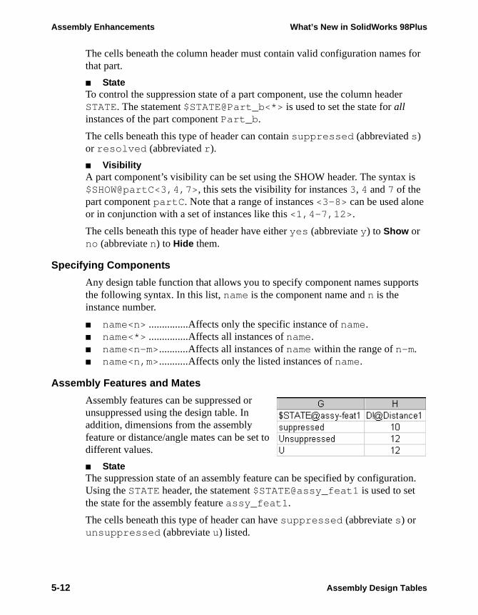
Assembly Enhancements What’s New in SolidWorks 98Plus
is
rts
ion.
The cells beneath the column header must contain valid configuration names for that part.
■ StateTo control the suppression state of a part component, use the column header STATE. The statement $STATE@Part_b<*> is used to set the state for all instances of the part component Part_b.
The cells beneath this type of header can contain suppressed (abbreviated s) or resolved (abbreviated r).
■ VisibilityA part component’s visibility can be set using the SHOW header. The syntax$SHOW@partC<3,4,7>, this sets the visibility for instances 3, 4 and 7 of the part component partC. Note that a range of instances <3-8> can be used alone or in conjunction with a set of instances like this <1,4-7,12>.
The cells beneath this type of header have either yes (abbreviate y) to Show or no (abbreviate n) to Hide them.
Specifying Components
Any design table function that allows you to specify component names suppothe following syntax. In this list, name is the component name and n is the instance number.
■ name<n> ...............Affects only the specific instance of name.■ name<*> ...............Affects all instances of name.■ name<n-m>...........Affects all instances of name within the range of n-m.■ name<n,m>...........Affects only the listed instances of name.
Assembly Features and Mates
Assembly features can be suppressed or unsuppressed using the design table. In addition, dimensions from the assembly feature or distance/angle mates can be set to different values.
■ StateThe suppression state of an assembly feature can be specified by configuratUsing the STATE header, the statement $STATE@assy_feat1 is used to set the state for the assembly feature assy_feat1.
The cells beneath this type of header can have suppressed (abbreviate s) or unsuppressed (abbreviate u) listed.
5-12 Assembly Design Tables
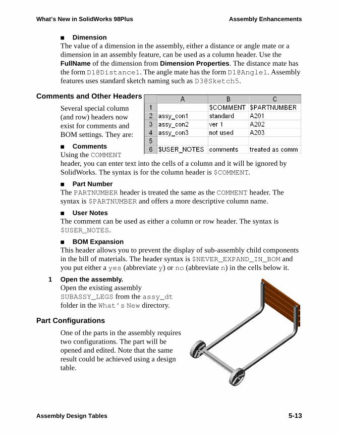
What’s New in SolidWorks 98Plus Assembly Enhancements
■ DimensionThe value of a dimension in the assembly, either a distance or angle mate or a dimension in an assembly feature, can be used as a column header. Use the FullName of the dimension from Dimension Properties. The distance mate has the form D1@Distance1. The angle mate has the form D1@Angle1. Assembly features uses standard sketch naming such as D3@Sketch5.
Comments and Other Headers
Several special column (and row) headers now exist for comments and BOM settings. They are:
■ CommentsUsing the COMMENT header, you can enter text into the cells of a column and it will be ignored by SolidWorks. The syntax is for the column header is $COMMENT.
■ Part NumberThe PARTNUMBER header is treated the same as the COMMENT header. The syntax is $PARTNUMBER and offers a more descriptive column name.
■ User NotesThe comment can be used as either a column or row header. The syntax is $USER_NOTES.
■ BOM ExpansionThis header allows you to prevent the display of sub-assembly child components in the bill of materials. The header syntax is $NEVER_EXPAND_IN_BOM and you put either a yes (abbreviate y) or no (abbreviate n) in the cells below it.
1 Open the assembly.Open the existing assembly SUBASSY_LEGS from the assy_dt folder in the What’s New directory.
Part Configurations
One of the parts in the assembly requires two configurations. The part will be opened and edited. Note that the same result could be achieved using a design table.
Assembly Design Tables 5-13
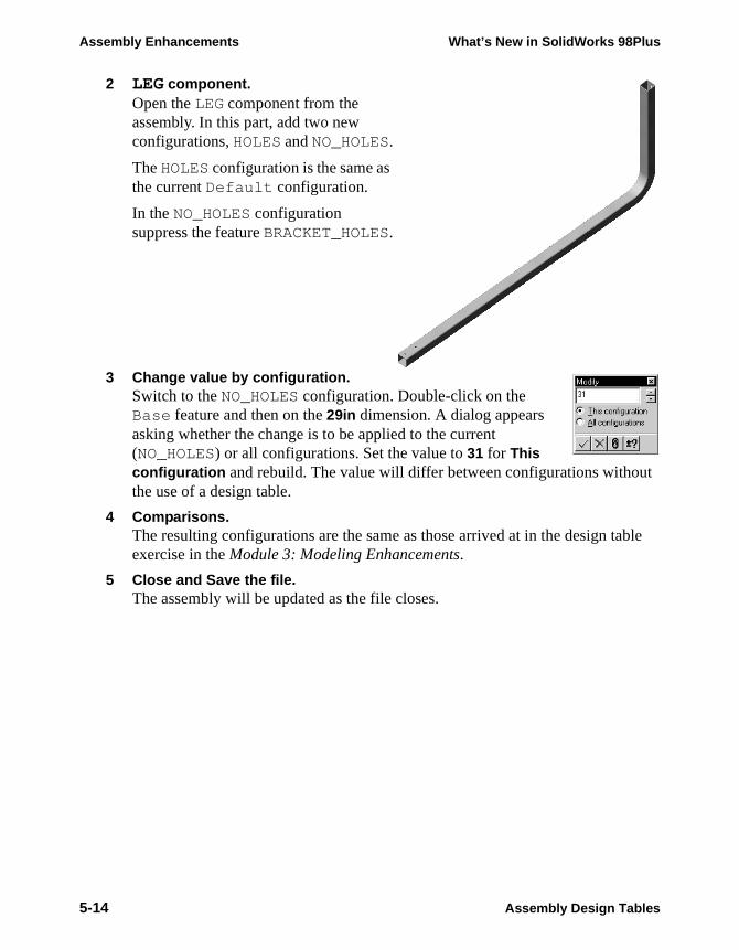
Assembly Enhancements What’s New in SolidWorks 98Plus
2 LEG component.Open the LEG component from the assembly. In this part, add two new configurations, HOLES and NO_HOLES.
The HOLES configuration is the same as the current Default configuration.
In the NO_HOLES configuration suppress the feature BRACKET_HOLES.
3 Change value by configuration.Switch to the NO_HOLES configuration. Double-click on the Base feature and then on the 29in dimension. A dialog appears asking whether the change is to be applied to the current (NO_HOLES) or all configurations. Set the value to 31 for This configuration and rebuild. The value will differ between configurations without the use of a design table.
4 Comparisons.The resulting configurations are the same as those arrived at in the design table exercise in the Module 3: Modeling Enhancements.
5 Close and Save the file.The assembly will be updated as the file closes.
5-14 Assembly Design Tables
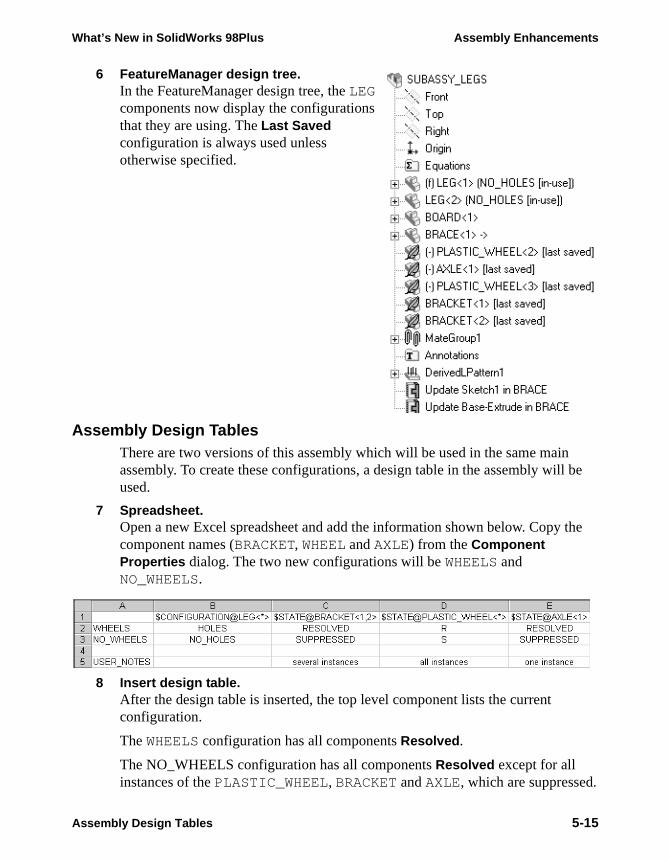
What’s New in SolidWorks 98Plus Assembly Enhancements
6 FeatureManager design tree.In the FeatureManager design tree, the LEG components now display the configurations that they are using. The Last Saved configuration is always used unless otherwise specified.
Assembly Design TablesThere are two versions of this assembly which will be used in the same main assembly. To create these configurations, a design table in the assembly will be used.
7 Spreadsheet.Open a new Excel spreadsheet and add the information shown below. Copy the component names (BRACKET, WHEEL and AXLE) from the Component Properties dialog. The two new configurations will be WHEELS and NO_WHEELS.
8 Insert design table.After the design table is inserted, the top level component lists the current configuration.
The WHEELS configuration has all components Resolved.
The NO_WHEELS configuration has all components Resolved except for all instances of the PLASTIC_WHEEL, BRACKET and AXLE, which are suppressed.
Assembly Design Tables 5-15
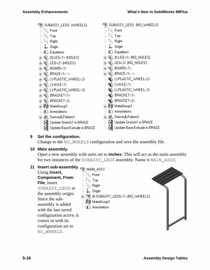
Assembly Enhancements What’s New in SolidWorks 98Plus
9 Set the configuration.Change to the NO_WHEELS configuration and save the assembly file.
10 Main assembly.Open a new assembly with units set to inches. This will act as the main assembly for two instances of the SUBASSY_LEGS assembly. Name it MAIN_ASSY.
11 Insert sub-assembly.Using Insert, Component, From File, insert SUBASSY_LEGS at the assembly origin. Since the sub-assembly is added with the last saved configuration active, it comes in with its configuration set to NO_WHEELS.
5-16 Assembly Design Tables
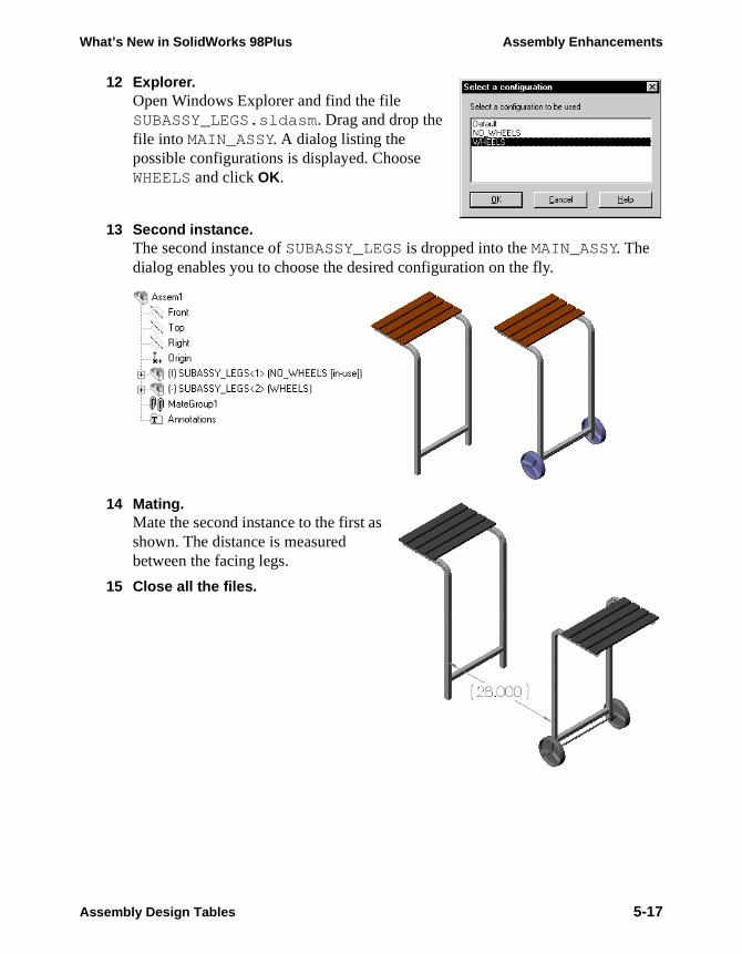
What’s New in SolidWorks 98Plus Assembly Enhancements
12 Explorer.Open Windows Explorer and find the file SUBASSY_LEGS.sldasm. Drag and drop the file into MAIN_ASSY. A dialog listing the possible configurations is displayed. Choose WHEELS and click OK.
13 Second instance.The second instance of SUBASSY_LEGS is dropped into the MAIN_ASSY. The dialog enables you to choose the desired configuration on the fly.
14 Mating.Mate the second instance to the first as shown. The distance is measured between the facing legs.
15 Close all the files.
Assembly Design Tables 5-17

Assembly Enhancements What’s New in SolidWorks 98Plus
5-18 Assembly Design Tables