Embed Size (px)
Citation preview
8/12/2019 Solid State Lightning Rewiew - Alonso
http://slidepdf.com/reader/full/solid-state-lightning-rewiew-alonso 1/9
6 IEEE INDUSTRIAL ELECTRONICS MAGAZINE DECEMBER 2013 1932-4529/13/$31.00©2013IEEE
A System Review
CHRISTIAN BRAÑAS,FRANCISCO J. AZCONDO,and J. MARCOS ALONSO
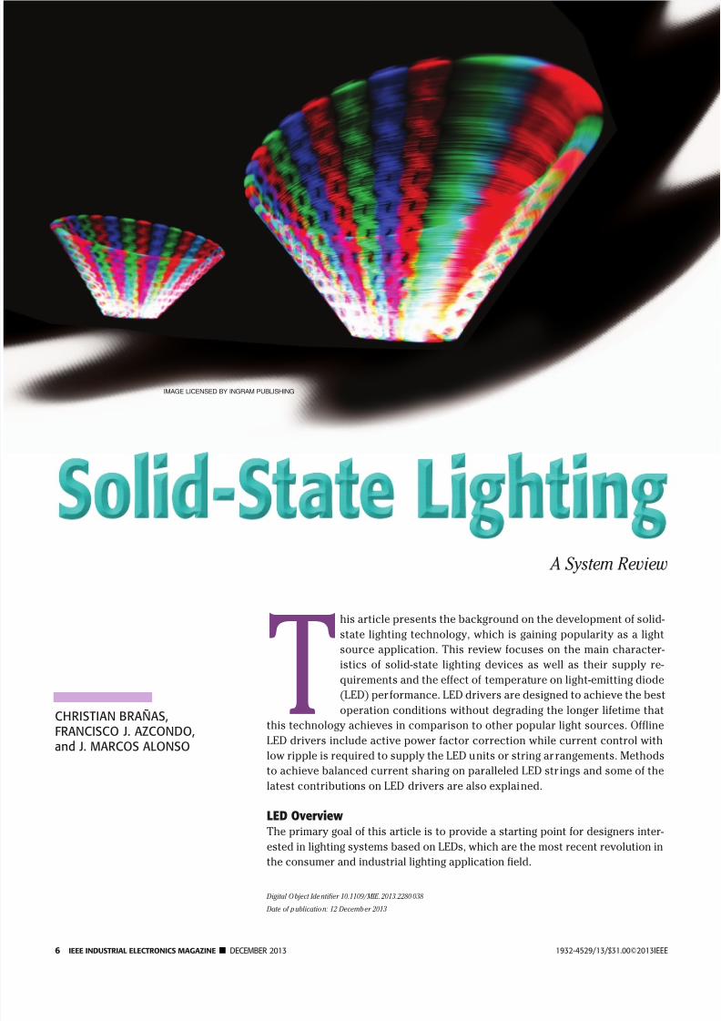
This article presents the background on the development of solid-
state lighting technology, which is gaining popularity as a light
source application. This review focuses on the main character-
istics of solid-state lighting devices as well as their supply re-
quirements and the effect of temperature on light-emitting diode
(LED) performance. LED drivers are designed to achieve the best
operation conditions without degrading the longer lifetime thatthis technology achieves in comparison to other popular light sources. Offline
LED drivers include active power factor correction while current control with
low ripple is required to supply the LED units or string arrangements. Methods
to achieve balanced current sharing on paralleled LED str ings and some of the
latest contributions on LED drivers are also explained.
LED Overview The primary goal of this article is to provide a starting point for designers inter-
ested in lighting systems based on LEDs, which are the most recent revolution in
the consumer and industrial lighting application field.
Digital O bject Identifier 10.1109/MIE.2013.2280 038
Date of publication: 12 December 2013
IMAGE LICENSED BY INGRAM PUBLISHING

8/12/2019 Solid State Lightning Rewiew - Alonso
http://slidepdf.com/reader/full/solid-state-lightning-rewiew-alonso 2/9
DECEMBER 2013 IEEE INDUSTRIAL ELECTRONICS MAGAZINE 7
The emission mechanism of LEDs
is electroluminescence. Contrary to
the perception that this technology
is something new, to find the founda-
tion of LEDs based on semiconduc-
tor materials, one should look back
to 1907, when Captain Henry Joseph
Round observed the electrolumines-
cence phenomenon when a currentflowed through a crystal of silicon
carbide [1]. Independently, in 1923,
the Russian radio technician Oleg V.
Lossev made the first attempt to ex-
plain the electroluminescence in p-n
junctions with a scientific approach,
describing the current versus volt-
age characteristic of the new device
[2], [3]. The modern age of LED tech-
nology can be dated to the beginning
of the 1960s, when Robert Hall, Nick
Holonyak, Marshall Nathan, and Rob-ert Rediker reported simultaneously
[4]–[6] the laser emission of gallium
arsenide crystals. LEDs have been
commercially available since then in
red, amber, and green colors. The ap-
plications of LEDs have mainly been
signaling, seven-segment displays,
and remote control.
The next remarkable breakthrough
in LED technology was the develop-
ment of the first feasible blue LED by
Shuji Nakamura at Nichia Corpora-
tion [7]. The blue LED paved the way
for the development of white-light
sources by mixing red, green, and
blue (RGB) LEDs [8]–[10]. As this
method could prove expensive, the
method most widely used to produce
white light based on LED technology
is by adding a phosphor layer to a
blue LED to modify the emission spec-trum. The phosphor emits yellow light
under excitation of the blue light, and
the resulting mixture produces the ap-
pearance of white light [11]. Recently,
phosphor-free white-light LEDs have
been proposed [12], providing a more
efficient light source. In this case, the
white light is produced in a multilayer
monolithic structure where blue and
yellow light are emitted from different
active regions.
Today, white LEDs are still un-der development. Every year, the
lumen per watt (lm/W) efficiency is
increased, while the cost is dimin-
ished. For example, several devices
from the OSRAM OSLON SSL 80 [13]
and Philips Lumileds Luxeon Rebel
ES [14] families are available, achiev-
ing higher energy efficiency than
100 lm/W (Figure 1). Although these
values of efficiency are obtained for
a pulsed regime to avoid the effect
of the self-heating of the die, such
devices are competitive with tradi-
tional light sources. Because of the
nature of the LED spotlight, it is pos-
sible to design a very efficient optic
to bring the light where it is needed
[15], reducing light pollution. On the
other hand, improvements in the
packaging, such as the flip-chip tech-
nology [16] combined with the use ofnew materials such as ceramic sub-
strates increase the thermal capabili-
ty [17] of the device, which increases
reliability [18], lifetime up to 50,000
h, and light efficiency. Together with
the aforementioned advantages, LED
technology also overcomes draw-
backs of traditional discharge lamps
such as hot reignition, acoustic reso-
nance, and warm-up time. LED tech-
nology is environmentally friendly
and free of mercury and infrared andultraviolet radiation.
Organic LEDs
Electronics based on organic materi-
als started in 1977 when Heeger, Mac
Diarmid, and Shirakawa published a
paper describing a polymeric conduc-
tor [19]. The term organic is associat-
ed with the use of polymers based on
some types of carbon composite. De-
vices such as transistors, diodes, and
even integrated circuits are being im-
plemented in this technology, receiv-
ing time and resource investments
from different companies. The advan-
tages of polymer-based electronics
are mainly the mechanical properties,
such as high flexibility, and the sim-
plicity of the manufacturing process.
(a) (b) (c)
FIGURE 1 – An example of an LED fixture for outdoor application. (a) Lateral view with heatsink detail. (b) Front view showing a four LED matrix arrange-ment. (c) Front view with the LEDs on.
The blue LED paved the way for the development
of white-light sources by mixing red, green,
and blue LEDs.

8/12/2019 Solid State Lightning Rewiew - Alonso
http://slidepdf.com/reader/full/solid-state-lightning-rewiew-alonso 3/9
8 IEEE INDUSTRIAL ELECTRONICS MAGAZINE DECEMBER 2013
In addition, this technology is environ-
mentally friendly.
Electroluminescence is found inorganic materials, as was reported in
the early 1950s [20]. The first organic
LED (OLED) was developed by Tang
and Van Slyke in 1987 [21]. The device
was obtained by vacuum evaporation
of organic small-molecule material
with a metallic cathode on a conduc-
tive substrate. The first OLED based
on polymers was created in 1990 by
Buroughs et al. [22], with a single-
layer device of polyphenylenevinilene
made by using a spin coating process.Presently, OLEDs based on small mol-
ecules and polymers are feasible, with
similar performances for both families
of devices (Figure 2).
Because of the organic nature of
OLEDs, it is possible to achieve uni-
form light emission along a large sur-
face, which is especially suitable for
display applications. OLED technology
allows self-emitting displays, without
the necessity of backlighting [23]. For
lighting applications, the luminous
rendering of the OLEDs is still low,
being about 50 lm/W. The research ef-
fort on OLEDs is focused on increas-
ing the luminous rendering as well as
enlarging the emitting surface and ex-
tending the device life. Typically, the
luminance of OLEDs decreases down
to 50% of its initial value after 15,000 h.
The degradation of the luminance of
OLED devices is caused basically by
two mechanisms: electrode degrada-
tion and the intrinsic decrement of the
electroluminescence efficiency of theemissive area [24].
Recently, devices based on field-
induced polymer electroluminescence
(FIPEL) have been reported [25] as a
potential alternative to OLEDs. FIPEL
devices are formed by a multilayer
structure of polymers and carbon
nanotubes, achieving an enhanced
electroluminescence emission in ac
operation.
Indoor LightingAdvances in domotic, wired, and wire-
less communication systems and the
so-called Internet of Things are avail-
able technologies to optimize the opera-
tion of the lighting system according to
different criteria such as safety, com-
fort, work place specifications, and en-
ergy savings. The fast response of LEDs
under turn-on, turn-off, and dimming
commands makes them superior to pre-
vious lighting technologies for smart
lighting system implementations.
Solid-state lighting is well suited
to some special requirements for
indoor lighting, such as ambience
creation and decorative light. Ambi-
ence creation is not a minor question
as it is related, among other effects,
to the circadian rhythm of human
beings [26]. The benefits of the prop-
er light, according to the time of day,
have been proven in hospitals and
working places. LED lighting also has
other advantages such as the pos-
sible reconfiguration of the lighting
infrastructure for meeting specific
requirements. Recently, the innova-
tive idea of implementing a dedi-
cated dc microgrid in buildings to
supply LED-based lighting systems
has been proposed [27]. This idea di-rectly links modern lighting systems
to renewable energy sources, e.g.,
photovoltaic systems. Sometimes,
economic reasons and installation
times drive a different approach, e.g.,
retrofitting the infrastructure [28].
To make the most of old instal lations,
manufacturers provide LED lamps
designed for direct replacement of
fluorescent or halogen lamps. In such
a case, special attention must be paid
to the thermal management of theLED lamp [29], [30].
OLED technology also fulfils some
of the requirements for indoor light-
ing. White OLEDs provide a more uni-
form light source, avoiding glare and
flicker effects, which increases the
comfort of users. Moreover, the color
rendering of OLEDs is better than that
of fluorescent lamps, and they can
also save energy.
Outdoor LightingOne significant advantage of LED
lamps in comparison to high-intensity
discharge lamps is the absence of
warm-up time as well as acoustic
resonance and hot reignition prob-
lems. This feature overcomes some
safety issues of outdoor lighting
installations and facilitates control.
The most significant energy savings
can be achieved by using sensors
that detect the presence of pedestri-
ans or vehicles on the street to adjust
the light to a safe level. Additionally,
LED technology allows the design of
very efficient optics for the lamp to
focus the light where it is required. In
this way, the highway is uniformly il-
luminated, offering better comfort for
drivers, while using less energy and
reducing light pollution. Finally, the
installation of LED luminaries in open
spaces makes heat dissipation easier,
approaching the maximum renderingof the lamp in terms of lm/W.
(a) (b)
FIGURE 2 – OLEDs can emit light uniformly, even over a large surface area. (a) A flexible amberOLED and (b) a flexible white OLED. (Photos courtesy of OSRAM SYLVANIA.)
LED technology is environmentally friendly and free
of mercury and infrared and ultraviolet radiation.

8/12/2019 Solid State Lightning Rewiew - Alonso
http://slidepdf.com/reader/full/solid-state-lightning-rewiew-alonso 4/9
DECEMBER 2013 IEEE INDUSTRIAL ELECTRONICS MAGAZINE 9
Thermal IssuesOne of the most important aspects when
designing an LED-based lighting system
is its thermal design [31]. As in any other
semiconductor-based device, an LED’s
electrical characteristics are strongly
dependent on its operating temperature.
Furthermore, temperature also strongly
affects the LED photometric character-istics. An increase in LED temperature
produces a decrease in LED operating
voltage, and it also modifies the equiva-
lent series resistance [32]. If the LED cur-
rent is regulated, that is, kept constant,
an increase in temperature will generate
a decrease in the LED light output. Ad-
ditionally, an increase in LED junction
temperature also produces a decrease
in light output due to a higher level of
nonradiating recombination inside the
crystal lattice. Therefore, an increasein temperature can lead to a substantial
light output decrease.
Junction temperature also affects the
maximum current that an LED can han-
dle for a given total thermal resistance
of the heat transfer path (junction to
environment). For example, for a given
total thermal resistance of 70 °C/W, an
LED can manage 350 mA up to 50 °C
ambient temperature but only 200 mA
for an ambient temperature of 75 °C.
The manufacturers usually provide
current derating curves, which give
the maximum allowable current
through the LED for a given ambient
temperature and thermal resistance.
The junction temperature also
modifies the color of the light emitted
by a monochromatic LED because of
changes in its spectrum peak wave-
length. In white LEDs, the junction tem-perature produces variations in the
light color temperature that can lead to
low color rendition.
Because of their low operation
temperature, LEDs can barely transfer
heat by infrared emission, and there-
fore, most of the heat is transferred
from the junction to the case by heat
conduction mechanisms. The typical
dynamic model to study the tempera-
ture distribution in an LED fixture is
illustrated in Figure 3.Thermal impedance given by a par-
allel thermal capacitance ( )C xy and a
series thermal resistance ( ) R xy exists
between any two materials that make
up the fixture, from the LED junction
to the surrounding environment. The
thermal resistances and capacitances
of a given fixture are usually obtained
experimentally in a laboratory test.
Once obtained, the model can suc-
cessfully be used to predict the LED
junction temperature under various
operating modes, including analog
and pulsewidth modulation (PWM)
dimming. The electrical, photometri-
cal, and thermal characteristics are
dependent on each other. Interesting
studies on this topic can be found in
[33] and [34]. It should be noted that
the model presented in Figure 3 must
only be used as a first approximationto solve the LED thermal design prob-
lem. There are some effects that are not
considered in this model, for example,
heat radiation, phosphor conversion
losses, and three-dimesional effects. To
accurately predict the LED junction
temperature, precise finite element
analysis is employed [35]. Thermal
modeling is usually combined with
mechanical modeling, which takes
into account the mechanical stress in
the materials due to the effect of dif-ferent thermal expansion coefficients.
Driver ArchitectureThe static and dynamic character-
istics of an LED matrix impose the
specifications of the drivers. In an
initial approach, LED light sources
lead to a simplification of the power
supply compared with the electronic
ballast counterparts required to sup-
ply discharge lamps. Ballast circuits
have a double function: to stabilize
the discharge arc, whose small-
signal impedance is negative, and to fix
the operation point at the required
current/power level with limited rip-
ple. Only the second function remains
as a general objective for LED drivers.
The current mode control is gener-
ally adopted because the current is
the electrical variable with closest
relationship to the emitted light and
the power dissipated in the LED, due
to the rigid current versus voltage
J u n c t i o
n
C a s
e
I s o l a t i n g T a p
e
H e a t s i n
k
A m b i e n
t
T J T C R CI R IHT I T H
R HAR JC
C JC C CI C IH C HA T A
Ambient
TemperatureLEDPowerP D
FIGURE 3 – A simplified thermal model of an LED fixture: different complex mechanisms that
result in heat sources, such as conduction losses in LEDs, driver operation, and phosphor con- version, are not detailed.
V dc +
– –
I o
R s
+
V dc/dc
f B
FIGURE 4 – Current control is achieved viathe voltage sensed in the shunt resistor R s.
White OLEDs provide a more uniform light source,
avoiding glare and flicker effects, which increases
the comfort of users.

8/12/2019 Solid State Lightning Rewiew - Alonso
http://slidepdf.com/reader/full/solid-state-lightning-rewiew-alonso 5/9
10 IEEE INDUSTRIAL ELECTRONICS MAGAZINE DECEMBER 2013
characteristic of the diode. Moreover,
the need to limit the current ripple de-
rives from the fast lux versus current
response of the LED.
Low-power applications such as
flashlights or bicycle lights require few
LEDs arranged in a single string thatcan be driven by a dc-to-dc converter
controlled in current mode. Commer-
cial controllers designed to control dc-
to-dc converters in voltage mode can
be adapted for driving LEDs [36], [37]
(see Figure 4), paying special attention
to reducing the feedback voltage so
that excessive power dissipation in the
current sensor ( Rs ) can be avoided.
Drivers to supply higher-power
indoor and outdoor illumination-
oriented applications face different
challenges, not just current control, to
optimize the use of LEDs. For lightingsystems connected to the utility, stan-
dards such as International Electro-
technical Commission (IEC)-61000-3-2
and Energy Star must be taken into
account. As is illustrated in Figure 5,
offline power supplies include power
factor correction as a single stage [38],
[39], integrated [40]–[43], or with a
two-stage arrangement where the first
stage supplies a front-end dc voltage
for a second stage that controls the
LED array current.
One important aspect to consider
when designing LED drivers is reli-
ability. This is because LEDs have ex-
tremely long lifetimes that can reach
105 hours under some circumstances.
When developing offline drivers,
large capacitances are required to
smooth the changing low-frequency
line voltage. They are needed because
designers like to have an LED cur-
rent with low line-frequency ripple so
that the emitted light is high quality
and able to be used in any applica-
tion. Electrolytic capacitors are usu-
ally employed because of their highcapacitance/(volume * cost) figure of
merit, but they can barely reach
10,000 h lifetime under strict tem-
perature conditions. In this aspect,
integrated converters can help to attain
low LED current ripple while maintain-
ing low filter capacitances with a lim-
ited cost and volume. Figure 6 shows
the block diagram of an integrated LED
driver, which includes a power factor
correction to provide low-current har-
monic injection into the mains, and
a dc–dc converter to supply the LED
lamp with low ripple current [37].
An example of an integrated con-
verter is illustrated in Figure 7, where
two buck-boost converters have been
merged by sharing their controlled
switches. In this way, a single switch
converter is obtained, thus simplify-
ing the control circuitry and reducing
cost [40], [41]. Using this converter, a
70-W LED driver with a 12-µF bulk ca-
pacitor and a 3-µF output capacitor
with 86% efficiency has been demon-
strated [41]. Electrolytic capacitors
were avoided so that the converter
lifetime matches that of the LED lamp.
The requirements of Energy Star and
IEC-61000-3-2 are also fulfilled. In
addition, the converter admits am-
plitude (AM) and PWM dimming to
control LED lamp luminosity.
Another area of research on the
use of integrated converters for LEDdrivers is presented in [42]. There, a
V ac
I o
R s
+
–
V ac/dc
f B
I o
R s
+
–
V dc/dc
f B
V ac
ac/dcC B
(a) (b)
FIGURE 5 – (a) Single- and (b) two-stage architectures used for LED drivers.
i g
v g
C B
i o Lamp
+
–
v o
+
–
IntegratedPFC/dc–dc
Stage
FIGURE 6 – A high power factor integratedLED driver can be used to maintain lowripple current.
D 1 D 2 D 3LED Lamp
LineL1
L2 C 2
+
+C 1
M
FIGURE 7 – An integrated double buck-boost converter simplifies control circuitry andreduces costs.

8/12/2019 Solid State Lightning Rewiew - Alonso
http://slidepdf.com/reader/full/solid-state-lightning-rewiew-alonso 6/9
DECEMBER 2013 IEEE INDUSTRIAL ELECTRONICS MAGAZINE 11
buck-boost converter integrated with
a buck converter is used to supply two
low-voltage LED arrays used in high-
pressure lamp retrofit applications.
A general study on the use of integrat-
ed converters for high-reliability LED
drivers can be found in [43]. The in-
tegration of resonant converters and
high power factor correction stagesas offline LED drivers is also possible.
Resonant converters can help to in-
crease the driver efficiency owing to
their inherently low switching losses.
Some converters have been investigated
in recent literature [44]–[46].
Dimming ControlThe modification of the LED current
reference, i.e., amplitude modulation
Line
Integrated
High PowerFactor
LED Driver
LED Lamp
PWM
DimmingSwitch
CurrentSense
ActualLED MeanCurrent
LED MeanCurrent Error
LED MeanCurrent Reference
Low-PassFilter
PWMDimming Switch
DimmingLevel
PWMDimming
Generator
LED Peak
Current Reference
ErrorAmplifier
DimmingDuty Cycle
+ –
∑
FIGURE 8 – A high-frequency PWM dimming circuit ensures constant LED peak current andregulated LED mean current.
2
Ch2 Average888 mA
Ch2 Frequency500.8 Hz
Ch2 500 mAΩ Ch2400 µs
0.00000 s 19 January 201211:01:50
P 1.24 AA
T
2
Ch2 Average1.347 A
Ch2 Frequency500.8 Hz
Ch2 500 mAΩ Ch2400 µs
0.00000 s 19 January 201211:04:11
P 1.24 AA
T
2
Ch2 Average766.6 mA
Ch2 Frequency499.1 Hz
Ch2 500 mAΩ Ch2400 µs
0.00000 s 19 January 201211:09:14
P 990 mAA
T
2
Ch2 Average888 mA
Ch2 Frequency501.2 Hz
Ch2 500 mAΩ Ch2400 µs
0.00000 s 19 January 201212:09:59
P 1.24 AA
T
(a) (b)
(c) (d)
FIGURE 9 – Current prof iles at 500 Hz for dimming implementation of LED lamps: (a) PWM, (b) bilevel, (c) negative sawtooth, and (d) low-resolution sine.

8/12/2019 Solid State Lightning Rewiew - Alonso
http://slidepdf.com/reader/full/solid-state-lightning-rewiew-alonso 7/9
12 IEEE INDUSTRIAL ELECTRONICS MAGAZINE DECEMBER 2013
(AM) of the LED current, to perform
dimming control modifies the LED
color rendering; while a low-speedPWM generates undesired flickering
effects and, possibly, utility ac cur-
rent distortion. On the other hand, the
high-speed performance is not com-
patible with the low-frequency band-
width required for the control of the
power factor correction (PFC) stage
output voltage where it is necessary
to keep the input current shape pro-
portional to the utility voltage.
Integrated converters are particu-
larly suitable to incorporate high-frequency PWM dimming capability.
A special control circuitry can be in-
corporated into the driver so that the
LED peak current is kept constant ateach dimming level [47], [48]. Pro-
vided that a greater PWM dimming
frequency is chosen than the con-
verter cut-off frequency, which usu-
ally means a few kilohertz, dimming
can be performed without distorting
the line current so that harmonic in-
jection related standards can be sat-
isfied. Figure 8 illustrates the block
diagram of this circuit.
Basically, the LED mean current
reference is indirectly obtained bymultiplying the dimming level by the
desired LED peak current. The cur-
rent reference is then compared to
the actual LED mean current and the
difference is applied to an error ampli-
fier. The converter operates by regu-
lating the average LED current, even
in PWM mode, while maintaining the
LED peak current at the desired value
so that constant color coordinatesare assured.
A combination of amplitude and
PWM is also proposed to create different
current profiles [49], [50], while prevent-
ing flicker effects. The experimental LED
current waveforms illustrating this case
are shown in Figure 9.
In many situations, LED lamps are
used to replace incandescent lamps
in applications where dimming is at-
tained using inexpensive TRIAC-based
dimmers. In these applications, LEDdrivers must be designed so that the
LED power can be adjusted depend-
ing on the TRIAC firing angle. A very
typical solution used for this purpose
is based on the flyback converter op-
erating in discontinuous conduction
mode (DCM) or in the boundary be-
tween continuous conduction mode
and DCM. In this manner, automatic
power factor correction is achieved,
and some kind of control algorithm
can be used to detect the TRIAC firing
angle and control the LED power [51].
Current SharingThe distribution of LEDs in a set of dif-
ferent strings to form an array requires
action to be taken to balance the cur-
rent distribution among the strings
when the paralleled strings are not
matched to avoid uneven current shar-
ing. As has been studied for the par-
allel connection of junction devices,
sufficiently large series impedance in
each LED string (Figure 10) makes the
dispersion of the current negligible.
This solution, however, decreases the
efficiency of the whole lamp.
On the other hand, active cur-
rent control in each string, as shown
in Figure 11 [52], not only assures
adequate current distribution but
also solves the problem of using LED
strings with different i versus v charac-
teristics, as is the case of LED stringsemitting light of different colors so
ac/dc
or
dc/dc
V o
V ref +
–
R
I o = V ref / R Current
Control
Unit
V o I o
I o 1 I o 2 I oN
FIGURE 10 – The current of LED strings is adjusted by independent current sources.
dc/dcV o 1
V o
dc/dc
V dc
+
–
I oN
I o 2
I o 1
dc/dc
V oN
FIGURE 11 – Independent active control of each LED string allows LEDs of different colors tobe used together to create a variety of lighting effects.
The static and dynamic characteristics of an LED
matrix impose the specifications of the drivers.

8/12/2019 Solid State Lightning Rewiew - Alonso
http://slidepdf.com/reader/full/solid-state-lightning-rewiew-alonso 8/9
DECEMBER 2013 IEEE INDUSTRIAL ELECTRONICS MAGAZINE 13
that a variety of light ambiences can
be created.
Nondissipative current balance is
achieved using the coupling of single
or multiple secondary side windings in
a transformer core [53], which is also
used for isolation purposes and to set a
convenient voltage level. Moreover, the
current balance is achieved with thehelp of coupled inductors [54]. In this
case, the current balance is achieved
in ac, so a later rectification and use of
a large capacitor filter are required.
ConclusionsRecent advances in LED and OLED
lamps cover most light source appli-
cations, such as signaling, illumina-
tion, decoration, and ambience, with
improvements in energy efficiency and
light control flexibility.The steep di /dv characteristic
of LED lamps and the effect of tem-
perature on the i – v curve and on
the deviation of the light emission
spectrum require a tightly regulated
current and limitation of the current
ripple to prevent flickering.
The dc bus and output capacitanc-
es are minimized in high-performance
LED drivers to avoid using short life-
time electrolytic capacitors. The PWM
is usually preferred to implement
dimming because the modulation of
the LED current amplitude may affect
color rendering, while combination of
amplitude and PWM paves the way
to carrying out a more flexible dim-
ing and color temperature adjustment
with better EMC.
The integration of the power fac-
tor correction and LED driver stages
results in a robust and cost-effective
solution. Recent contributions on in-
tegrated stages present novel high-
frequency PWM with fast dynamic
response to preserve the light chro-
maticity and power factor in dimming
operation.
AcknowledgmentThe authors would like to thank Jo
Olsen and Eliecer Muñoz from OSRAM
SYLVANIA for their help in obtain-
ing the OLED pictures that appear in
this article. This work was supportedin part by the Spanish Ministry of
Science (TEC—FEDER 2011-23612 andDPI2010-15889).
BiographiesChristian Brañas (branasc@unican.
es) received his Ph.D. degree in elec-
tronics engineering in 2001 from the
University of Cantabria, Santander,
Spain. In 1995, he joined the Micro-
electronic Engineering Group at the
University of Cantabria, where he
is currently an associate professor.
Since 1997, he has been involved inseveral research projects in the field
of power electronics for lighting ap-
plications. He is a coauthor of 15 in-
ternational journal publications and
more than 50 international conference
papers in this field. He also holds a
Spanish patent. He is a Member of the
IEEE and a member of the IEEE Indus-
trial Electronics Society.
Francisco J. Azcondo (azcondof@
unican.es) received his E.E. degree
from the Universidad Politécnica de
Madrid, Spain, in 1989 and the Ph.D.
degree from the University of Cantabria,
Spain, in 1993. He is currently a pro-
fessor in the TEISA Department at
ETS II y T, University of Cantabria,
Spain. Since 1997, he has been co-
ordinating research projects in the
field of lighting applications. He is a
coauthor of 35 international journal
publications, 16 of them in this field,
along with more than 50 international
conference papers. He was a guest
coeditor of the special section on
modern ballast technology and light-
ing applications of IEEE Transactions
on Industry Electronics in 2012 and
coorganizer of special sessions fo-
cused on lighting at IEEE-IECON. He
is a Senior Member of the IEEE and a
member of the IEEE Industrial Elec-
tronics Society.
J. Marcos Alonso (marcos@uniovi.
es) received his M.Sc. degree and Ph.D.degree, both in electrical engineering,
from the University of Oviedo, Spain,in 1990 and 1994, respectively. Since
2007, he has been a full professor with
the Electrical Engineering Department
of the University of Oviedo. In the field
of power electronics for lighting appli-
cations, he has participated in more
than 20 research projects, has been
supervisor of eight Ph.D. theses, and
holds seven Spanish patents. Since
2002, he has served as an associate ed-
itor of IEEE Transactions on Power Elec-
tronics. He has been a co-guest editorof two special issues in lighting appli-
cations published in IEEE Transactions
on Power Electronics (2007) and IEEE
Transactions on Industrial Electronics
(2012). He also serves as secretary of
the IEEE Industry Applications Society
Industrial Lighting and Display Com-
mittee. He is a Senior Member of the
IEEE and a member of the IEEE Indus-
trial Electronics Society.
References[1] H. J. Round, “A note on carborundum,” Elec.
World , vol. 19, pp. 309, Feb. 1907.
[2] O. V. Lossev, “Wireless telegraphy and telepho-ny,” Telegrafia i Telefonia bez provodor , no. 18,pp. 61, 1923 and no. 26, pp. 403, 1924.
[3] O. V. Lossev, “Luminous carborundum detec-tor and detection effect and oscillations withcrystals,” Philos. Mag., vol. 6, no. 39, pp. 1024–1044, 1928.
[4] R. N. Hall, G. E. Fenner, J. D. Kingsley, T. J.Soltys, and R. O. Carlson, “Coherent light emis-sion from GaAs junctions,” Phys. Rev. Let t., vol. 9, no. 9, pp. 366–368, 1962.
[5] N. Holonyak and S. F. Bevacqua,“ Light emis-
sion from Ga(As1-XPX) junctions,” Appl . Phys. Let t ., vol. 1, no. 4, pp. 82–83, 1962.
[6] M. I. Nathan, W. P. Dumke, G. Burns, F. H. Dill,and G. Lasher, “Stimulated emission of ra-diation from GaAs P-N junctions”, Appl . Phys. Let t. vol. 1, no. 3, pp. 62–64, 1962.
[7] S. Nakamura, T. Mukai, M. Senoh, “Candela-class high-brightness InGaN/AlGaN double-heterostructure blue-light-emitting diodes,” Appl . Phys . Let t., vol. 64, no. 13, pp. 1687–1689,Mar. 1994.
[8] S. Muthu, F. J. P. Schuurmans, and M. D. Pashley,“Red, green, and blue LEDs for white light illumi-nation,” IEEE Select. Topics Quantum Electron.,vol. 8, no. 2, pp. 333–338, Mar./Apr. 2002.
[9] S. Muthu and J. Gaines, “Red, green and blueLED-based white light source: Implementation
challenges and control design,” in Proc. 38th IAS Annu. Meeting , 2003, vol. 1. pp. 515–522.
The integration of the power factor correction
and LED driver stages results in a robust and
cost-effective solution.

8/12/2019 Solid State Lightning Rewiew - Alonso
http://slidepdf.com/reader/full/solid-state-lightning-rewiew-alonso 9/9
14 IEEE INDUSTRIAL ELECTRONICS MAGAZINE DECEMBER 2013
[10] B. Ackermann, V. Schulz, C. Martiny, A. Hilgers,and X. Zhu, “Control of LEDs,” in Proc. 41st IAS Annu. Meeting , 2006, vol. 5, pp. 2608–2615.
[11] H. J. Yu, W. Chung, and S. H. Kim, “White lightemission from blue InGaN LED with hybridphosphor,” in Proc. 10th IEEE Int. Conf. Nano- technology Joint Symp. with Nano Korea 2010 ,August 17–20, Kintex, Korea, pp. 958–961.
[12] C. F. Lu, C. F. Huang, Y.-S. Chen, W. Y. Shiao,C.-Y. Chen, Y.-C. Lu, and C.-C. Yang, “Phosphor-free monolithic white-light LED,” IEEE Selec t.Topics Quantum Electron., vol. 15, no. 4,
pp. 1210–1217, July/Aug. 2009.[13] (2012, Apr. 11). OSLON SSL 80 Data Sheet
Version 1.0. Published by OSRAM OptoSemiconductors GmbH. [Online]. Available:http://catalog.osram-os.com/jsp/download.jsp?rootPath=/media/&name=LCW_CR7P.EC.pdf&docPath=Graphics/00067655_0.pdf&url=/media//_en/Graphics/00067655_0.pdf
[14] LUXEON Rebel ES Datasheet DS61. PhilipsLumileds Lighting Company. Available: www.philipslumileds.com/uploads/17/DS61-pdf
[15] S. Liu, K. Wang, Z. Chen, and X. Luo, “LED packag-ing and reliability for lighting applications,” in Proc.13th Int. Symp. Science and Technology of Lighting ,June 24–29, 2012, Troy, New York, pp. 271–285.
[16] C. Y. Tang, M. Y. Tsai, C. C. Lin, and L. B. Chang,“Thermal measurements and analysis of flip-
chip LED packages with and without under-fills,” in Proc. 5th Int. Microsystems Packaging Assembly and Circu its Technology Conf. (IM - PACT) , Oct. 20–22, 2010, pp. 1–4.
[17] J. J. Wierer, D. A. Steigerwald, M. R. Krames, J.J. O’Shea, M. J. Ludowise, G. Christenson, Y. C.Shen, C. Lowery, P. S. Martin, S. Subramanya, W.Götz, N. F. Gardner, R. S. Kern, and S. A. Stock-man, “High-power AlGaInN flip-chip light-emitting diodes,” Appl . Phys. Lett ., vol. 78, no.22, pp. 3379–2281, May 2001.
[18] M. Meneghini, G. Meneghesso, N. Trivellin, andE. Zanoni, “High-power LEDs for solid-statelighting: Reliability issues and degradationmodes,” in Proc. 13th Int. Symp. Science andTechnology of Lighting , June 24–29, 2012, Troy,New York, pp. 267–269.
[19] H. Shirakawa, E. J. Louis, A. G. MacDiarmid, C.K. Chiang, and A. J. Heeger, “Synthesis of electri-cally conducting organic polymers: Halogen de-rivatives of polyacetylene, (CH)x,” J. Soc. Chem.Commun., no. 16, pp. 578–580, 1977.
[20] A. Bernanose, “Electroluminescence of organ-ic compounds,” 1955, Br. J. Appl . Phys., vol. 6(Suppl. 4), pp. S54–S55, 1995.
[21] C. W. Tang, and S. A. Vanslyke, “Organic elec-troluminescent diodes,” Appl. Phys. Lett., vol. 51,no. 12, pp. 913–915, Sept. 1987.
[22] J. H. Buroughs, D. D. C. Bradley, A. R. Brown, R.N. Marks, K. D. Mackay, R. H. Friend, P. L. Burn,and A. B. Holmes, “Light emitting diodes basedon conjugated polymers,” Nature, vol. 347,no. 6293, pp. 539–541, Oct. 1990.
[23] W. F. Aerts, S. Verlaak, and P. Heremans, “Designof an organic pixel addressing circuit for an ac-
tive-matrix OLED display,” IEEE Trans. Electron Devices, vol. 49, no. 12, pp. 2124–2130, Dec. 2002.
[24] Z. D. Popovic and H. Aziz, “Reliability anddegradation of small molecule-based organiclight-emitting devices (OLEDs),” IEEE Selec t.Topics Quantum Electron., vol. 8, no. 2, pp. 362–371, Mar./Apr. 2002.
[25] Y. Chen, G. M. Smith, E. Loughman, Y. Li, W.Nie, and D. L. Carroll, “Effect of multi-walledcarbon nanotubes on electron injection andcharge generation in AC field-induced polymerelectroluminescence,” Org. Electron., vol. 14,no.1, pp. 8–18, Jan. 2013.
[26] M. G. Figueiro, “An overview of the non-visualeffects of light: Implications for new light sourc-es and lighting systems design,” in Proc. 13th Int. Symp. Science and Technology of Lighting , June24–29, 2012, Troy, New York, pp. 23–37.
[27] N. Narendran, “Updating a legacy: Tradingup Edison’s light bulb and electrical infra-structure,” in Proc. 13th Int. Symp. Science andTechnology of Lighting , June 24–29, 2012, Troy,New York, pp. 3–7.
[28] N. Chen and H. S.-H. Chung, “Driving tech-nology for retrofit LED lamp for fluorescent
lighting fixtures with electronic ballasts,” IEEE Trans. Power Elect ron., vol. 26, no. 2,pp. 588–601, 2011.
[29] T. Yasuda, J. Sasaki, Y. Takahara, and S.Oosawa, “A series of flat shaped LED lightengines with a heat-transfer solution,” in Proc. 13th Int. Symp. Science and Technologyof Lighting , June 24–29, 2012, Troy, New York,pp. 261–262.
[30] D. Gacio, J. M. Alonso, J. Garcia, M. S. Perdigao,E. S. Saraiva, and F. E. Bisogno, “Effects of thejunction temperature on the dynamic resis-tance of white LEDs,” IEEE Trans. Ind. Applicat.,vol. 49, no. 2, pp. 750, 760, Mar.–Apr. 2013.
[31] M.-H. Chang, D. Das, P. V. Varde, and M. Pecht,“Light emitting diodes reliability review,” Microelec tron. Reliab., vol. 52, no. 5, pp. 762–782, May 2012.
[32] J. M. Alonso, D. Gacio, A. J. Calleja, J. Ribas,and E. L. Corominas, “A study on LED retro-fit solutions for low-voltage halogen cyclelamps,” IEEE Trans. Ind . Applicat., vol. 48, no. 5,pp. 1673, 1682, Sept.–Oct. 2012.
[33] S. Y. R. Hui and Y. X. Qin, “A general photo-electro-thermal theory for light emitting diode(LED) systems,” in Proc. 24th Annu. IEEE Ap- plied Power Elect ronics Conf. Expo., APEC 2009,15–19, Feb. 2009, pp. 554, 562.
[34] Y. X. Qin, D. Y. Lin, H. S.-H. Chung, W. Yan,and S. Y. R. Hui, “Dynamic control of a light-emitting diode system based on the generalphoto-electro-thermal theory,” in Proc. IEEE En- ergy Conversion Congr and Expo., (ECCE), 20–24Sept. 2009, pp. 2815, 2820.
[35] V. C. Bender, O. Iaronka, M. A. D. Costa,
R. N. do Prado, and T. B. Marchesan, “Anoptimized methodology for LED lighting sys-tems designers,” in Proc. IEEE Industr y Appli- cations Society Annu. Meeting (IAS), Oct. 2012,pp. 1–8.
[36] H. van der Broeck, G. Sauerlander, and M.Wendt, “Power driver topologies and controlschemes for LEDs,” in Proc. 22nd Annu. IEEE Applied Power Electronics Conf., APEC 2007, pp.1319–1325.
[37] C. Danjiang and Z. Wei, “Application of LN2117series chips in White LED driver,” in Proc. 2nd Int. Conf. Sof tware Technology and Engineering(ICSTE), 2010, vol. 2, pp. 244–246.
[38] Y. Hu, L. Huber, and M. Jovanovic, “Single-stage flyback power factor- correction front-end for HB LED application,” in Proc. IEEE Industry Applications Society Annu. Meeting, IAS ,
2009, pp. 1–8.[39] D. G. Lamar, J. S. Zuniga, A. R. Alonso, M. R.
Gonzalez, and M. M. H. Alvarez, “A very simplecontrol strategy for power factor correctorsdriving high-brightness LEDs,” IEEE Trans. Power Electron. , vol. 24, no. 8, pp. 2032–2042,Aug. 2009.
[40] J. M. Alonso, J. Viña, D. G. Vaquero, G.Martínez, and R. Osorio, “Analysis and designof the integrated double buck–boost converteras a high-power-factor driver for power-LEDlamps,” IEEE Trans. Ind. Electron., vol. 59, no. 4,pp. 1689–1697, Apr. 2012.
[41] J. M. Alonso, D. Gacio, J. Garcia, M. Rico-Secades, and M. A. Dalla Costa, “Analysis anddesign of the integrated double buck-boostconverter operating in full DCM for LED light-ing applications,” in Proc. 37th Annu. Conf. IEEE Indust rial Electronics Society, IECON 2011, 7–10Nov., pp. 2889, 2894.
[42] High-power-factor light-emitting diode lamppower supply without electrolytic capacitors forhigh-pressure-sodium lamp retrofit applications,” IET Power Elect ron ., vol. 6, no. 8, pp. 1502,1515, Sept. 2013.
[43] J. M. Alonso, D. Gacio, A. J. Calleja, F. Sichirollo,M. F. da Silva, M. A. D. Costa, and R. N. do Prado,“Reducing storage capacitance in offline LEDpower supplies by using integrated converters,”in Proc. IEEE Industry Applications Society Annu. Meeting, IAS 2012 , 7–11 Oct., pp. 1, 8.
[44] M. M. Peretz, M. Chen, N. Goyal, and A. Prodic,“A merged-stage high efficiency high powerfactor HB-LED converter without electrolyticcapacitor,” in Proc. PCIM Europe Conf., Nuremberg,Germany, May 2012, pp. 357–364.
[45] P. S. Almeida, M. A. D. Costa, J. M. Alonso, andH. A. C. Braga, “Application of series resonantconverters to reduce ripple transmission toLED arrays in offline drivers,” Electron. Lett.,vol. 49, no. 6, pp. 414, 415, Mar. 2013.
[46] W. Feng, F. C. Lee, and P. Mattavelli, “Optimaltrajectory control of burst mode for LLC reso-
nant converter,” IEEE Trans. Power Elect ron .,vol. 28, no. 1, pp. 457–466, Jan. 2013.
[47] D. Gacio, J. M. Alonso, L. Campa, M. Crespo,and M. Rico, Spanish Patent #2.364.308, 2012.
[48] D. Gacio, J. Marcos Alonso, J. Garcia, L. Cam-pa, M. J. Crespo, and M. Rico-Secades, “PWMseries dimming for slow-dynamics HPF LEDDrivers: the high-frequency approach,” IEEETrans. Ind. Electron., vol. 59, no. 4, pp. 1717–1727, Apr. 2012.
[49] K. H. Loo, Y. M. Lai, S.-C. Tan, and C. K. Tse,“On the color stability of phosphor-convertedwhite LEDs under DC, PWM and bilevel drive,” IEEE Trans. Power Electron., vol. 27, no. 2,pp. 974–984, Feb. 2012.
[50] C. Brañas, F. J. Azcondo, and R. Casanu-eva, “Modulation scheme for dimming high-brightness LED lamps,” in Proc . 13th Int. Symp. Science and Technology of Lighting , June 24–29,2012, Troy, New York, pp. 247–248.
[51] J. Zhang, H. Zeng, and T. Jiang, “A primary-side control scheme for high-power-factorLED driver with TRIAC dimming capability,” IEEE Trans. Power Electron., vol. 27, no. 11,pp. 4619–4629, 2012.
[52] Q. Hu and Z. Rane, “LED driver circuit withseries-input-connected converter cells oper-ating in continuous conduction mode,” IEEETrans. Power Electron., vol. 25, no. 3, pp. 574–582, Mar. 2010.
[53] X. K. Wu, J. M. Zhang, and Z. M. Qian, “A simpletwo-channel LED driver with automatic pre-cise current sharing,” IEEE Trans. Ind. Elec- tron., vol. 58, no. 10, pp. 4783–4788, 2011.
[54] J. Wang, J. M. Zhang, X. K. Wu, Y. Shi, and Z.
M. Qian, “A novel high efficiency and low-costcurrent balancing method for multi-LED driv-er,” in Proc. IEEE Energy Conversion Congr. and Expo., ECCE , 2011, pp. 2296–2301.