Embed Size (px)
Citation preview
®
D-1020MARCH 2001
Solid State BurnerManagement Controls Series
D10-20 forAutomatic Burners
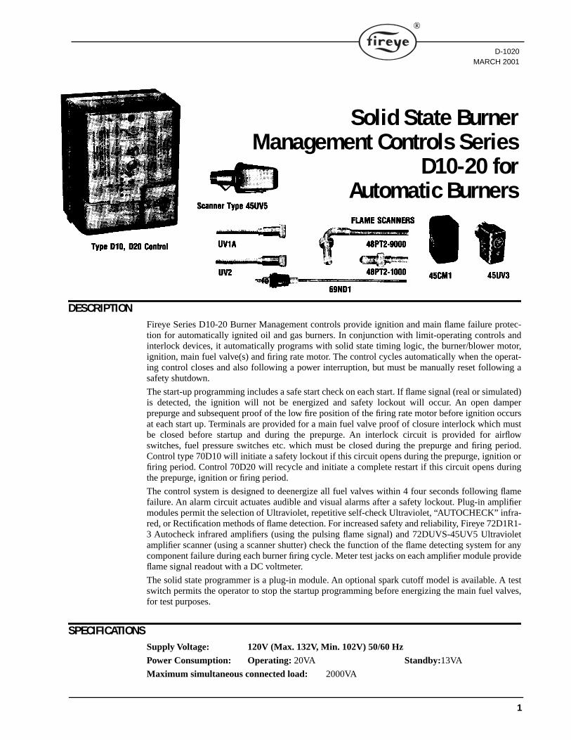
DESCRIPTIONFireye Series D10-20 Burner Management controls provide ignition and main flame failure protec-tion for automatically ignited oil and gas burners. In conjunction with limit-operating controls andinterlock devices, it automatically programs with solid state timing logic, the burner/blower motor,ignition, main fuel valve(s) and firing rate motor. The control cycles automatically when the operat-ing control closes and also following a power interruption, but must be manually reset following asafety shutdown.
The start-up programming includes a safe start check on each start. If flame signal (real or simulated)is detected, the ignition will not be energized and safety lockout will occur. An open damperprepurge and subsequent proof of the low fire position of the firing rate motor before ignition occursat each start up. Terminals are provided for a main fuel valve proof of closure interlock which mustbe closed before startup and during the prepurge. An interlock circuit is provided for airflowswitches, fuel pressure switches etc. which must be closed during the prepurge and firing period.Control type 70D10 will initiate a safety lockout if this circuit opens during the prepurge, ignition orfiring period. Control 70D20 will recycle and initiate a complete restart if this circuit opens duringthe prepurge, ignition or firing period.
The control system is designed to deenergize all fuel valves within 4 four seconds following flamefailure. An alarm circuit actuates audible and visual alarms after a safety lockout. Plug-in amplifiermodules permit the selection of Ultraviolet, repetitive self-check Ultraviolet, “AUTOCHECK” infra-red, or Rectification methods of flame detection. For increased safety and reliability, Fireye 72D1R1-3 Autocheck infrared amplifiers (using the pulsing flame signal) and 72DUVS-45UV5 Ultravioletamplifier scanner (using a scanner shutter) check the function of the flame detecting system for anycomponent failure during each burner firing cycle. Meter test jacks on each amplifier module provideflame signal readout with a DC voltmeter.
The solid state programmer is a plug-in module. An optional spark cutoff model is available. A testswitch permits the operator to stop the startup programming before energizing the main fuel valves,for test purposes.
SPECIFICATIONSSupply Voltage: 120V (Max. 132V, Min. 102V) 50/60 Hz
Power Consumption: Operating: 20VA Standby:13VA
Maximum simultaneous connected load: 2000VA
1
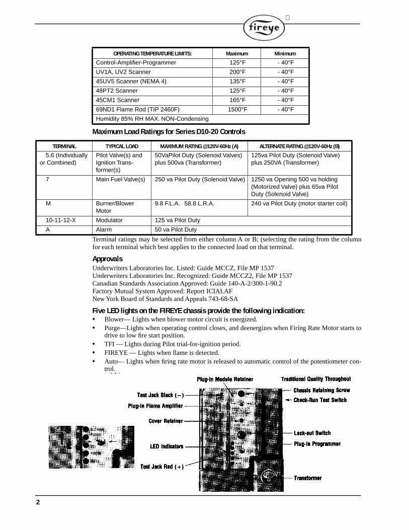
Maximum Load Ratings for Series D10-20 Controls
Terminal ratings may be selected from either column A or B; (selecting the rating from the columnfor each terminal which best applies to the connected load on that terminal.
ApprovalsUnderwriters Laboratories Inc. Listed: Guide MCCZ, File MP 1537Underwriters Laboratories Inc. Recognized: Guide MCCZ2, File MP 1537Canadian Standards Association Approved: Guide 140-A-2/300-1-90.2Factory Mutual System Approved: Report ICIAI.AFNew York Board of Standards and Appeals 743-68-SA
Five LED lights on the FIREYE chassis provide the following indication:• Blower— Lights when blower motor circuit is energized.• Purge—Lights when operating control closes, and deenergizes when Firing Rate Motor starts to
drive to low fire start position.• TFI — Lights during Pilot trial-for-ignition period.• FIREYE — Lights when flame is detected.• Auto— Lights when firing rate motor is released to automatic control of the potentiometer con-
trol.
OPERATING TEMPERATURE LIMITS: Maximum Minimum
Control-Amplifier-Programmer 125°F - 40°FUV1A, UV2 Scanner 200°F - 40°F45UV5 Scanner (NEMA 4) 135°F - 40°F48PT2 Scanner 125°F - 40°F45CM1 Scanner 165°F - 40°F69ND1 Flame Rod (TIP 2460F) 1500°F - 40°FHumidity 85% RH MAX. NON-Condensing
TERMINAL TYPICAL LOAD MAXIMUM RATING @120V-60Hz (A) ALTERNATE RATING @120V-60Hz (B)
5.6 (Individually or Combined)
Pilot Valve(s) and Ignition Trans-former(s)
50VaPilot Duty (Solenoid Valves) plus 500va (Transformer)
125va Pilot Duty (Solenoid Valve) plus 250VA (Transformer)
7 Main Fuel Valve(s) 250 va Pilot Duty (Solenoid Valve) 1250 va Opening 500 va holding (Motorized Valve) plus 65va Pilot Duty (Solenoid Valve)
M Burner/Blower Motor
9.8 F.L.A. 58.8 L.R.A. 240 va Pilot Duty (motor starter coil)
10-11-12-X Modulator 125 va Pilot Duty
A Alarm 50 va Pilot Duty
2
®
DESCRIPTION OF FIREYE SERIES D10-20 SYSTEM COMPONENTS
ORDERING INFORMATIONEach complete FIREYE series D10-20 system requires:
1. A control chassis and cover2. A plug-in Programmer Module3. A plug-in Amplifier Module4. A Flame Scanner5. A Wiring Base.
To specify a control system with a non-recycling running interlock circuit, with infrared(AUTOCHECK) flame detection for surface mounting, select the following:
• 70D10 Control and Cover• 71D60 Programmer• 72D1R1 Plug-In Amplifier• 48PT2 Flame Scanner (specify cable length and mount).• 60-1386 Wiring Base.
Note the following:1. When a FIREYE C-Series unit is replaced with a D-Series unit, the chassis retaining clip (for
quarter turn fastener) in the wiring base must be replaced with a threaded clip that is suppliedwith each D series control.
CONTROL CHASSIS AND COVER
70D10 — has non-recycling running interlock circuit70D20 — has recycling running interlock circuit and does not include purge interlock cir-cuit.
PLUG-IN PROGRAMMER MODULE
71D60 — Standard71D70 — with spark cutoff and 10 second main flame trial-for-ignition
PLUG-IN AMPLIFIER MODULE
AND FLAME SCANNER
AMPLIFIER FLAME-SCANNER
72DRT1Rectification
45CM1-1000 Photocell with filter 45CM1-1000Y Photocell without filter69ND1-1000K4 1/2" mount - 12" flame rod69ND1-1000K6 1/2" mount - 18" flame rod69ND1-1000K8 1/2" mount - 24" flame rod
72D1R1 Intra-red (IR) AUTOCHECK
72D1R3For special applications, note below
48PT2-1003 1/2" straight mount 96" cable48PT2-9003 1/2" angle mount 96" cable48PT2-1007 1/2" straight mount 48" cable48PT2-9007 1/2" straight mount 48" cable
72DUV1Ultraviolet (UV)
UV1A3 1/2" mount 36" cableUV1A6 1/2" mount 72" cableUV2 3/8" mount 36" cable45UV3-1050 3/4" mount, cast aluminum hous-ing, 8’ wireUV8A 1/2" right angle, no shielding
72DUVS4. Ultraviolet Repetitive Self-check 2-4 sec. FFRT.
72DUVS1T. Ultraviolet Repetitive Self-Check 1 sec. FFRT.
45UV5-1009 1 " mount, 72" wire leads.
WIRING BASE 60-1386-2 Standard base for surface mounting60-1466-2 Open base for cabinet mounting.
CAUTION: The 72D1R1 is not to be used with solid fuel applications, it is designed for oilfog rejection. The 72D1R3 is suitable for all fuel applications and does not contain oil fogrejection. Equipment should be tested for the proper application of this amplifier to avoidproperty damage or personal injury.
3
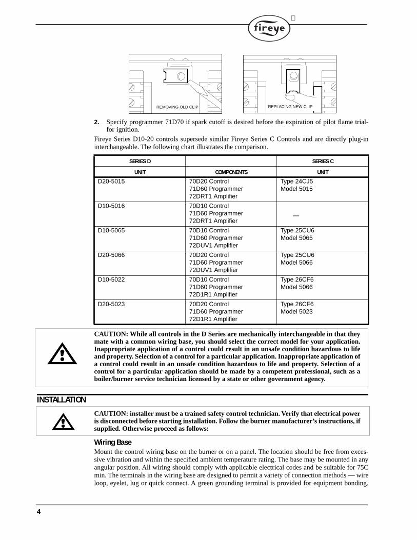
2. Specify programmer 71D70 if spark cutoff is desired before the expiration of pilot flame trial-for-ignition.
Fireye Series D10-20 controls supersede similar Fireye Series C Controls and are directly plug-ininterchangeable. The following chart illustrates the comparison.
CAUTION: While all controls in the D Series are mechanically interchangeable in that theymate with a common wiring base, you should select the correct model for your application.Inappropriate application of a control could result in an unsafe condition hazardous to lifeand property. Selection of a control for a particular application. Inappropriate application ofa control could result in an unsafe condition hazardous to life and property. Selection of acontrol for a particular application should be made by a competent professional, such as aboiler/burner service technician licensed by a state or other government agency.
INSTALLATION
CAUTION: installer must be a trained safety control technician. Verify that electrical poweris disconnected before starting installation. Follow the burner manufacturer’s instructions, ifsupplied. Otherwise proceed as follows:
Wiring BaseMount the control wiring base on the burner or on a panel. The location should be free from exces-sive vibration and within the specified ambient temperature rating. The base may be mounted in anyangular position. All wiring should comply with applicable electrical codes and be suitable for 75Cmin. The terminals in the wiring base are designed to permit a variety of connection methods — wireloop, eyelet, lug or quick connect. A green grounding terminal is provided for equipment bonding.
SERIES D SERIES C
UNIT COMPONENTS UNIT
D20-5015 70D20 Control71D60 Programmer72DRT1 Amplifier
Type 24CJ5Model 5015
D10-5016 70D10 Control71D60 Programmer72DRT1 Amplifier
—
D10-5065 70D10 Control71D60 Programmer72DUV1 Amplifier
Type 25CU6Model 5065
D20-5066 70D20 Control71D60 Programmer72DUV1 Amplifier
Type 25CU6Model 5066
D10-5022 70D10 Control71D60 Programmer72D1R1 Amplifier
Type 26CF6Model 5066
D20-5023 70D20 Control71D60 Programmer72D1R1 Amplifier
Type 26CF6Model 5023
REMOVING OLD CLIP REPLACING NEW CLIP
4
®
Circuit recommendations are provided on page 8. Consult with the factory for assistance with non-standard applications.
ELECTRICAL RATINGSVA ratings (not specified as pilot duty) permit the connection of transformers and similar deviceswhose inrush current is approximately the same as their running current. VA pilot duty ratings permitthe connection of relays, solenoid valves, lamps, etc. whose total operating load does not exceed 10times the rating.
Running and locked rotor ratings permit the connection of relays, solenoid valves, lamps, etc. whosetotal operating load does not exceed the published rating and whose total inrush current does notexceed 10 times the rating.
Running and locked rotor ratings are intended for motors. VA and VA pilot duty loads may be addedto a motor load provided the total load does not exceed the published rating.
CAUTION: Published load ratings assume that no contact be required to handle inrushcurrent more often than once in 15 seconds. The use of control switches, solenoids, relays, etc.which chatter will lead to premature failure of switches in the Fireye control. Similarly thecontacts cannot be expected to handle short circuit currents without damage. It is importantto run through a test operation (with fuel shut off) following the tripping of a circuit breaker,a blown fuse or any known instance of chattering.
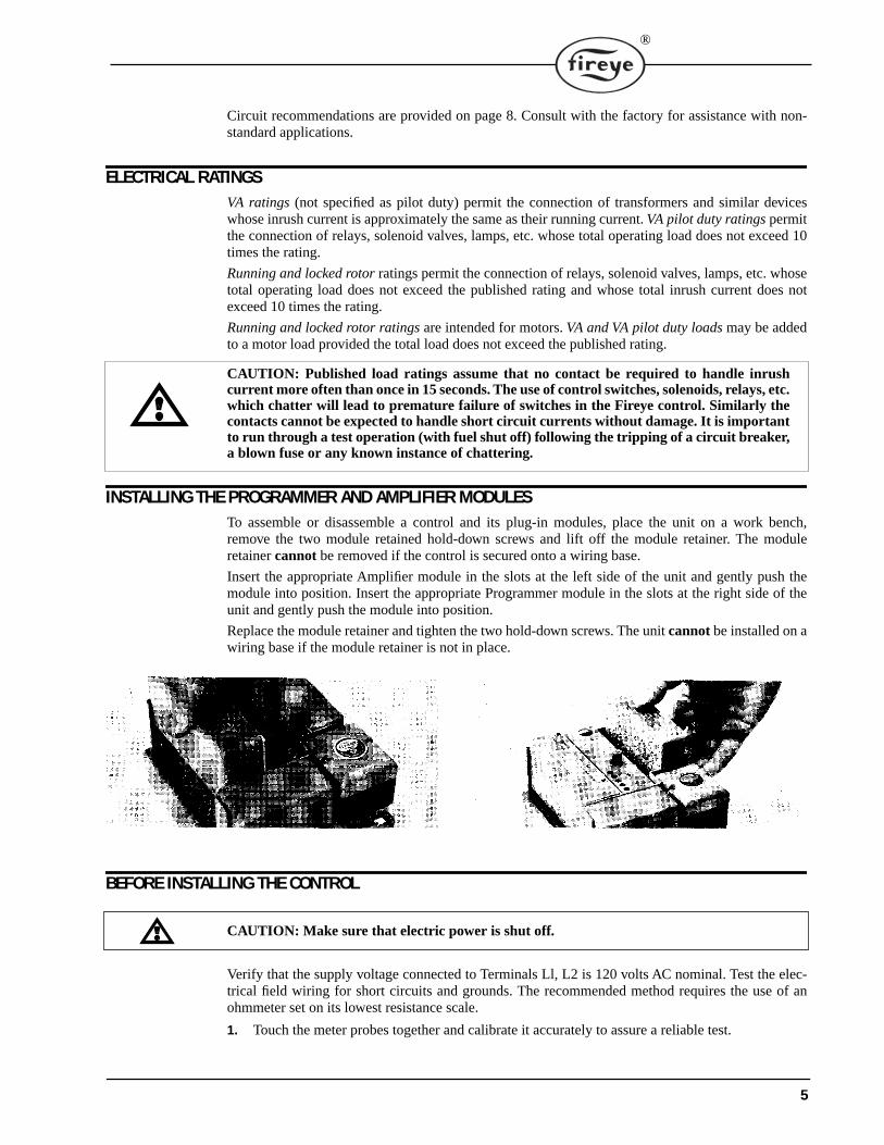
INSTALLING THE PROGRAMMER AND AMPLIFIER MODULESTo assemble or disassemble a control and its plug-in modules, place the unit on a work bench,remove the two module retained hold-down screws and lift off the module retainer. The moduleretainer cannot be removed if the control is secured onto a wiring base.
Insert the appropriate Amplifier module in the slots at the left side of the unit and gently push themodule into position. Insert the appropriate Programmer module in the slots at the right side of theunit and gently push the module into position.
Replace the module retainer and tighten the two hold-down screws. The unit cannot be installed on awiring base if the module retainer is not in place.
BEFORE INSTALLING THE CONTROL
CAUTION: Make sure that electric power is shut off.
Verify that the supply voltage connected to Terminals Ll, L2 is 120 volts AC nominal. Test the elec-trical field wiring for short circuits and grounds. The recommended method requires the use of anohmmeter set on its lowest resistance scale.
1. Touch the meter probes together and calibrate it accurately to assure a reliable test.
5
2. Disconnect the neutral wire (L2) from the control system at the power source. Clip one metertest lead to the grounded green terminal on the lower right side of the wiring base and with theother probe touch each other terminal. At no time should the meter read other than infinity.
3. Reconnect the neutral wire (L2) at the power source. Remove.the test probe from the groundedterminal and reconnect it to Terminal L2 in the wiring base. With the other probe, touch eachother terminal. It is normal to obtain a resistance reading on the meter at some terminals duringthis test as there are resistive loads (coils, transformers, lamps, etc.) connected whose normalDC resistance may be less than 5 ohms. However, at no time should the test meter read zeroohms.
4. If either a ground or a short circuit is detected, it must be eliminated before the control isplugged into the wiring base and power turned on. Otherwise, the control may be destroyed orimproper operation occur.
INSTALLING THE CONTROL
CAUTION: Make sure that electric power is shut off.
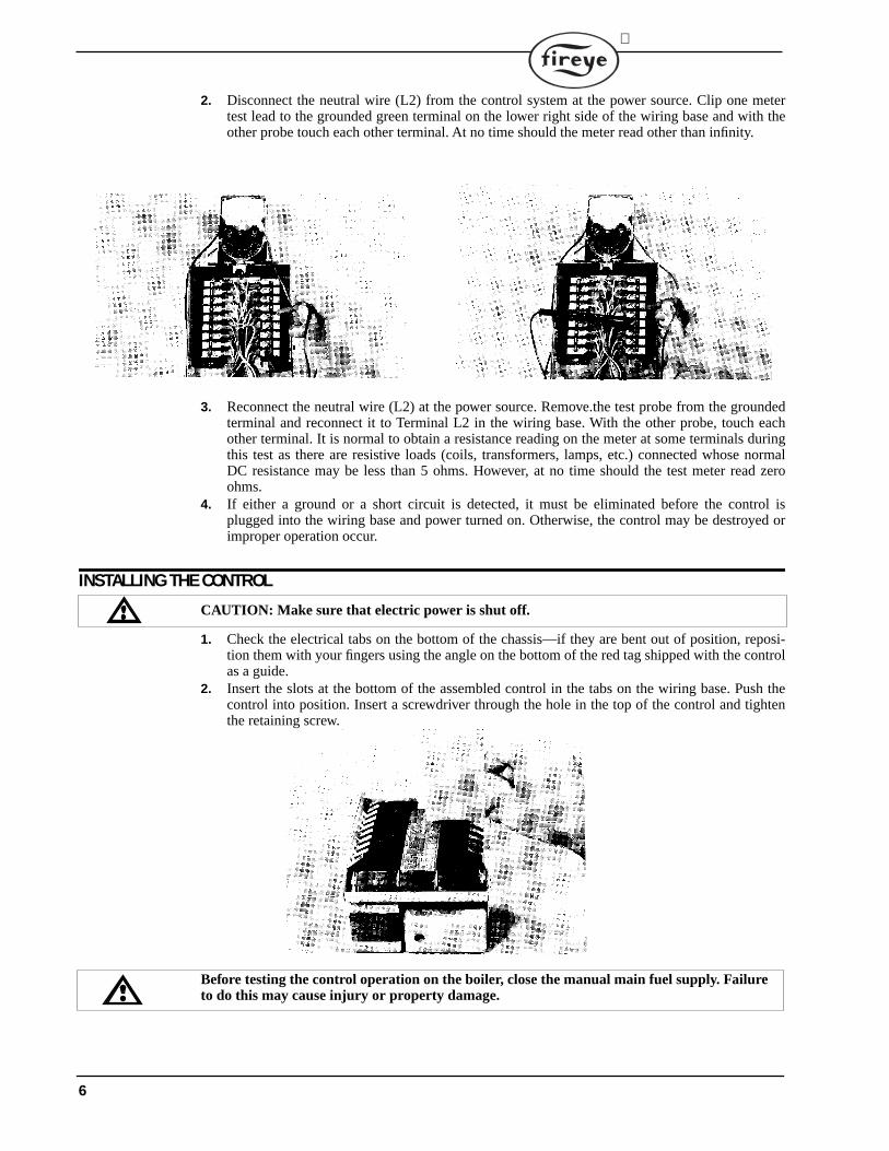
1. Check the electrical tabs on the bottom of the chassis—if they are bent out of position, reposi-tion them with your fingers using the angle on the bottom of the red tag shipped with the controlas a guide.
2. Insert the slots at the bottom of the assembled control in the tabs on the wiring base. Push thecontrol into position. Insert a screwdriver through the hole in the top of the control and tightenthe retaining screw.
Before testing the control operation on the boiler, close the manual main fuel supply. Failureto do this may cause injury or property damage.
6
®
Step: 1. Close the manual mainStep: 2. Recheck all limit circuit wiring for proper operation and correct connection.Step: 3. Confirm that the automatic main fuel valves are wired to terminal 7.Step: 4. Power the control and electrically check the proper sequence of operation according to the
Operation section in this bulletin.Step: 5. After assuring yourself that all interlocks and valves are properly wired and that the
sequence of operation is correct, open the manual main shut-off valve and proceed cau-tiously through the boiler light off process. Check all safety interlocks for proper shut downof the boiler.
INSTALLATION—UV SCANNERSWhere possible, obtain the Burner Manufacturer's Instructions for mounting the scanner. This infor-mation is available for most standard burners manufactured. The scanner mounting should complywith the following General Instructions:
1. Position the UVI, UV2 scanner within 18 inches of the flame to be monitored, the 45UV5within 30 inches, closer if possible.
2. Select a scanner location that will remain within the ambient temperature limits of the UV Scan-ner. If cooling is required, use an insulating coupling (Fireye #35-69 for UVI, UV2 Scanners,#35-127-1 for 45UV5) to reduce conducted heat.
3. The UVI, UV2, 45UV5 Scanners are designed to seal off the sight pipe up to I PSI pressure.Higher furnace pressures should be sealed off. To seal off positive furnace pressure up to 100PSI for UVI, UV2 Scanners, install a quartz window coupling (#60-1257). For 45UV5 Scan-ners, use #60-1199 coupling. Add cooling air to reduce the scanner sight pipe temperature.
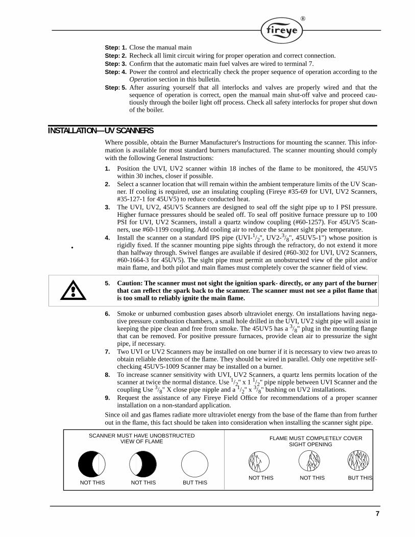
4. Install the scanner on a standard IPS pipe (UVI-1/2'', UV2-3/8", 45UV5-1") whose position isrigidly fixed. If the scanner mounting pipe sights through the refractory, do not extend it morethan halfway through. Swivel flanges are available if desired (#60-302 for UVI, UV2 Scanners,#60-1664-3 for 45UV5). The sight pipe must permit an unobstructed view of the pilot and/ormain flame, and both pilot and main flames must completely cover the scanner field of view.
5. Caution: The scanner must not sight the ignition spark- directly, or any part of the burnerthat can reflect the spark back to the scanner. The scanner must not see a pilot flame thatis too small to reliably ignite the main flame.
6. Smoke or unburned combustion gases absorb ultraviolet energy. On installations having nega-tive pressure combustion chambers, a small hole drilled in the UVI, UV2 sight pipe will assist inkeeping the pipe clean and free from smoke. The 45UV5 has a 3/8" plug in the mounting flangethat can be removed. For positive pressure furnaces, provide clean air to pressurize the sightpipe, if necessary.
7. Two UVI or UV2 Scanners may be installed on one burner if it is necessary to view two areas toobtain reliable detection of the flame. They should be wired in parallel. Only one repetitive self-checking 45UV5-1009 Scanner may be installed on a burner.
8. To increase scanner sensitivity with UVI, UV2 Scanners, a quartz lens permits location of thescanner at twice the normal distance. Use 1/2" x 1 1/2" pipe nipple between UVI Scanner and thecoupling Use 3/8" X close pipe nipple and a 1/2'' x 3/8" bushing on UV2 installations.
9. Request the assistance of any Fireye Field Office for recommendations of a proper scannerinstallation on a non-standard application.
Since oil and gas flames radiate more ultraviolet energy from the base of the flame than from furtherout in the flame, this fact should be taken into consideration when installing the scanner sight pipe.
BUT THISNOT THIS NOT THIS
FLAME MUST COMPLETELY COVERSIGHT OPENING
SCANNER MUST HAVE UNOBSTRUCTEDVIEW OF FLAME
NOT THIS NOT THIS BUT THIS
7
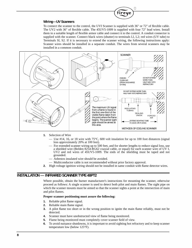
Wiring—UV ScannersTo connect the scanner to the control, the UVI Scanner is supplied with 36" or 72" of flexible cable.The UV2 with 36" of flexible cable. The 45UV5-1009 is supplied with four 72" lead wires. Installthem in a suitable length of flexible armor cable and connect it to the control. A conduit connector issupplied with the scanner. Connect black wires (shutter) to terminals Ll, L2; red wires (UV tube) toTerminals Sl, S2. If it is necessary to extend the scanner wiring, the following instructions apply:Scanner wires should be installed in a separate conduit. The wires from several scanners may beinstalled in a common conduit.
1. Selection of Wire— Use #14, 16, or 18 wire with 75°C, 600 volt insulation for up to 100 foot distances (signal
loss approximately 20% at 100 feet).— For extended scanner wiring up to 500 feet, and for shorter lengths to reduce signal loss, use
a shielded wire (Belden 8254-RG62 coaxial cable, or equal) for each scanner wire of UV I,UV2 and red wires of 45UV5-1009. The ends of the shielding must be taped and notgrounded.
— Asbestos insulated wire should be avoided.— Multiconductor cable is not recommended without prior factory approval.
2. High voltage ignition wiring should not be installed in same conduit with flame detector wires.
INSTALLATION — INFRARED SCANNER TYPE 48PT2Where possible, obtain the burner manufacturer's instructions for mounting the scanner, otherwiseproceed as follows: A single scanner is used to detect both pilot and main flames. The sight pipe onwhich the scanner mounts must be aimed so that the scanner sights a point at the intersection of mainand pilot flames.
Proper scanner positioning must assure the following:
1. Reliable pilot flame signal.2. Reliable main flame signal.3. A pilot flame too short or in the wrong position to ignite the main flame reliably, must not be
detected.4. Scanner must have unobstructed view of flame being monitored.5. Flame being monitored must completely cover scanner field of view.6. To avoid nuisance shutdowns, it is important to avoid sighting hot refractory and to keep scanner
temperature low (below 125°F).
The maximum UV signal from a flame is found in the first one-third of the visible flame taken from the point where the flame begins. The scanner sight pipe should be aimed at this area.
DO NOT EXTENDMORE THANHALF-WAY INTOREFRACTORY
SCANNER
FORCEDCLEAN AIR(FROM DISCHARGEOF FAN)
METHODS OF COOLING SCANNER
INSULATINGTUBING
SEALING UNION FORCED
AIR
EXTEND SIGHTING TUBE6”(1524) OR 8”(2032)
DO NOT EXTEND MORE THANHALF-WAY INTO REFRACTORY
8
®
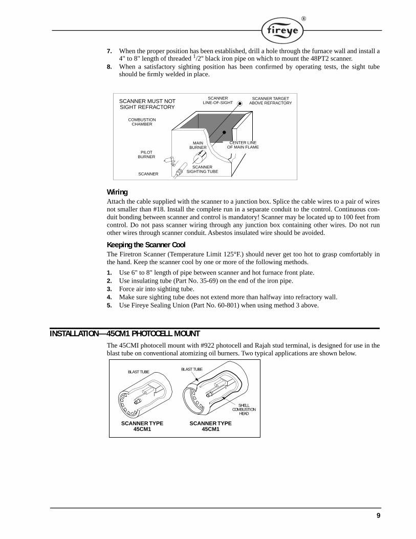
7. When the proper position has been established, drill a hole through the furnace wall and install a4" to 8" length of threaded 1/2'' black iron pipe on which to mount the 48PT2 scanner.
8. When a satisfactory sighting position has been confirmed by operating tests, the sight tubeshould be firmly welded in place.
WiringAttach the cable supplied with the scanner to a junction box. Splice the cable wires to a pair of wiresnot smaller than #18. Install the complete run in a separate conduit to the control. Continuous con-duit bonding between scanner and control is mandatory! Scanner may be located up to 100 feet fromcontrol. Do not pass scanner wiring through any junction box containing other wires. Do not runother wires through scanner conduit. Asbestos insulated wire should be avoided.
Keeping the Scanner CoolThe Firetron Scanner (Temperature Limit 125°F.) should never get too hot to grasp comfortably inthe hand. Keep the scanner cool by one or more of the following methods.
1. Use 6" to 8" length of pipe between scanner and hot furnace front plate.2. Use insulating tube (Part No. 35-69) on the end of the iron pipe.3. Force air into sighting tube.4. Make sure sighting tube does not extend more than halfway into refractory wall.5. Use Fireye Sealing Union (Part No. 60-801) when using method 3 above.
INSTALLATION—45CM1 PHOTOCELL MOUNTThe 45CMI photocell mount with #922 photocell and Rajah stud terminal, is designed for use in theblast tube on conventional atomizing oil burners. Two typical applications are shown below.
CENTER LINEOF MAIN FLAME
SCANNERLINE-OF-SIGHT
SCANNER TARGETABOVE REFRACTORY
COMBUSTIONCHAMBER
PILOTBURNER
SCANNER
SCANNERSIGHTING TUBE
MAINBURNER
SCANNER MUST NOTSIGHT REFRACTORY
SCANNER TYPE 45CM1
SCANNER TYPE 45CM1
BLAST TUBEBLAST TUBE
SHELLCOMBUSTION
HEAD
9
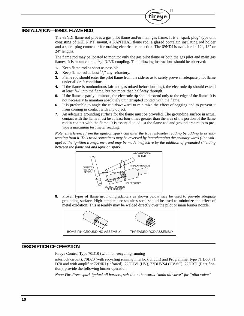
INSTALLATION—69ND1 FLAME RODThe 69NDI flame rod proves a gas pilot flame and/or main gas flame. It is a “spark plug” type unitconsisting of 1/2ll N.P.T. mount, a KANTHAL flame rod, a glazed porcelain insulating rod holderand a spark plug connector for making electrical connection. The 69NDI is available in 12", 18" or24" lengths.
The flame rod may be located to monitor only the gas pilot flame or both the gas pilot and main gasflames. It is mounted on a 1/2” N.P.T. coupling. The following instructions should be observed:
1. Keep flame rod as short as possible.2. Keep flame rod at least 1/2" any refractory.3. Flame rod should enter the pilot flame from the side so as to safely prove an adequate pilot flame
under all draft conditions.4. If the flame is nonluminous (air and gas mixed before burning), the electrode tip should extend
at least 1/2" into the flame, but not more than half-way through.5. If the flame is partly luminous, the electrode tip should extend only to the edge of the flame. It is
not necessary to maintain absolutely uninterrupted contact with the flame.6. It is preferable to angle the rod downward to minimize the effect of sagging and to prevent it
from coming in contact with any object.7. An adequate grounding surface for the flame must be provided. The grounding surface in actual
contact with the flame must be at least four times greater than the area of the portion of the flamerod in contact with the flame. It is essential to adjust the flame rod and ground area ratio to pro-vide a maximum test meter reading.
Note: Interference from the ignition spark can alter the true test-meter reading by adding to or sub-tracting from it. This trend sometimes may be reversed by interchanging the primary wires (line volt-age) to the ignition transformer, and may be made ineffective by the addition of grounded shieldingbetween the flame rod and ignition spark.
8. Proven types of flame grounding adapters as shown below may be used to provide adequategrounding surface. High temperature stainless steel should be used to minimize the effect ofmetal oxidation. This assembly may be welded directly over the pilot or main burner nozzle.
DESCRIPTION OF OPERATIONFireye Control Type 70D10 (with non-recycling running
interlock circuit), 70D20 (with recycling running interlock circuit) and Programmer type 71 D60, 71D70 and with amplifier 72DIRI (infrared), 72DUVI (UV), 72DUVS4 (UV-SC), 72DRTI (Rectifica-tion), provide the following burner operation:
Note: For direct spark ignited oil burners, substitute the words “main oil valve” for “pilot valve.”
WRONG POSITIONOF ROD
INADEQUATE FLAME
PILOT BURNERCORRECT POSITION
OF PILOT FLAME
CORRECTPOSITIONOF ROD
BOMB FIN GROUNDING ASSEMBLY THREADED ROD ASSEMBLY
10
®
Start-up1. With power applied, the limit-operating control circuit closed and the main fuel valve interlock
closed, the burner/blower motor (Terminal M) is energized, the running interlock circuit (airflow switch) closes. The “Blower” indicator (LED), and “Purge” indicator (LED) lights.
2. The firing rate motor is driven toward the open damper position.3. Control type 70D10 - when the firing rate motor reaches its open damper position (Highfire), the
open damper interlock closes and initiates the prepurge interval of 30 seconds. If the interlockdoes not close, the programming will pause until it closes. Control type 70D20 - a prepurge of30 seconds is initiated
4. When the prepurge is completed, the “Purge” indicator (LED) goes out, the firing rate motor isdriven toward the low fire position.
5. Following the 30 second delay to permit the firing rate motor to reach the low fire position, acheck is made for the low fire start interlock. If it is not closed, the programming sequence willpause until it closes.
6. With proven low fire position, the spark ignition and pilot valve are energized (Terminal 5 and6). The “TFI” indicator (LED) lights.
7. Programmer 71D70 deenergizes the spark ignition after 5 seconds, when connected to Term. 5.8. When the pilot flame is proven, the “Fireye” indicator (LED) lights.9. Following a 10 second proven pilot stabilization period, the main fuel valve(s) (Terminal 7) is
energized. The TFI indicator (LED) goes out.10. With 71D60 programmer, following a 10 second (Terminal 5) or 15 second (Terminal 6) main
flame trial for ignition, the pilot ignition is deenergized. With 71 D70 programmer, following a10 second main flame trial for ignition, the pilot ignition (Terminal 6) is deenergized. The firingrate motor is released to automatic control, and the “AUTO” indicator lights.
11. End of supervised start-up program.
Normal Shutdown1. When the operating control circuit opens, the main fuel valve is deenergized, the firing rate
motor is driven to the closed damper position.2. Following a 15 second post purge, the burner/blower motor is deenergized.3. All indicators (LED) go out.
11
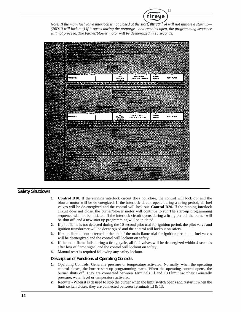
Note: If the main fuel valve interlock is not closed at the start, the control will not initiate a start up—(70D10 will lock out).If it opens during the prepurge—and remains open, the programming sequencewill not proceed. The burner/blower motor will be deenergized in 15 seconds.
Safety Shutdown1. Control D10. If the running interlock circuit does not close, the control will lock out and the
blower motor will be de-energized. If the interlock circuit opens during a firing period, all fuelvalves will be de-energized and the control will lock out. Control D20. If the running interlockcircuit does not close, the burner/blower motor will continue to run.The start-up programmingsequence will not be initiated. If the interlock circuit opens during a firing period, the burner willbe shut off, and a new start up programming will be initiated.
2. If pilot flame is not detected during the 10 second pilot trial for ignition period, the pilot valve andignition transformer will be deenergized and the control will lockout on safety.
3. If main flame is not detected at the end of the main flame trial for ignition period, all fuel valveswill be deenergized and the control will lockout on safety.
4. If the main flame fails during a firing cycle, all fuel valves will be deenergized within 4 secondsafter loss of flame signal and the control will lockout on safety.
5. Manual reset is required following any safety lockout.
Description of Functions of Operating Controls1. Operating Controls: Generally pressure or temperature activated. Normally, when the operating
control closes, the burner start-up programming starts. When the operating control opens, theburner shuts off. They are connected between Terminals Ll and 13.Llimit switches: Generallypressure, water level or temperature activated.
2. Recycle - When it is desired to stop the burner when the limit switch opens and restart it when thelimit switch closes, they are connected between Terminals Ll & 13.
12
®
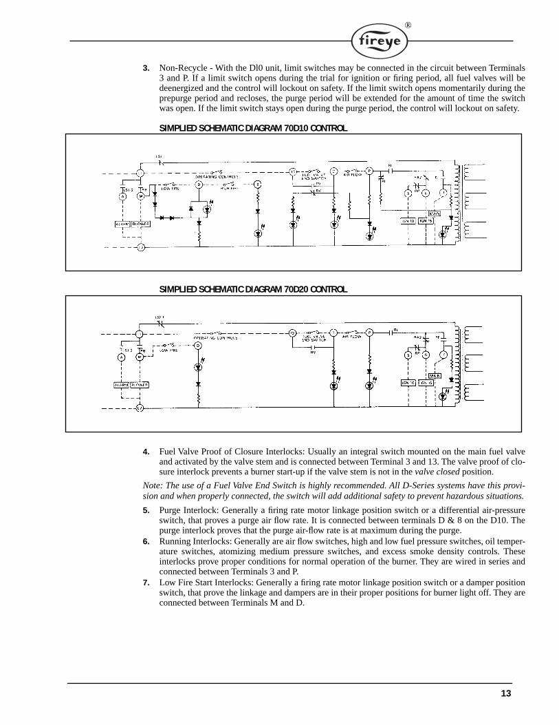
3. Non-Recycle - With the Dl0 unit, limit switches may be connected in the circuit between Terminals3 and P. If a limit switch opens during the trial for ignition or firing period, all fuel valves will bedeenergized and the control will lockout on safety. If the limit switch opens momentarily during theprepurge period and recloses, the purge period will be extended for the amount of time the switchwas open. If the limit switch stays open during the purge period, the control will lockout on safety.
SIMPLIED SCHEMATIC DIAGRAM 70D10 CONTROL
SIMPLIED SCHEMATIC DIAGRAM 70D20 CONTROL
4. Fuel Valve Proof of Closure Interlocks: Usually an integral switch mounted on the main fuel valveand activated by the valve stem and is connected between Terminal 3 and 13. The valve proof of clo-sure interlock prevents a burner start-up if the valve stem is not in the valve closed position.
Note: The use of a Fuel Valve End Switch is highly recommended. All D-Series systems have this provi-sion and when properly connected, the switch will add additional safety to prevent hazardous situations.
5. Purge Interlock: Generally a firing rate motor linkage position switch or a differential air-pressureswitch, that proves a purge air flow rate. It is connected between terminals D & 8 on the D10. Thepurge interlock proves that the purge air-flow rate is at maximum during the purge.
6. Running Interlocks: Generally are air flow switches, high and low fuel pressure switches, oil temper-ature switches, atomizing medium pressure switches, and excess smoke density controls. Theseinterlocks prove proper conditions for normal operation of the burner. They are wired in series andconnected between Terminals 3 and P.
7. Low Fire Start Interlocks: Generally a firing rate motor linkage position switch or a damper positionswitch, that prove the linkage and dampers are in their proper positions for burner light off. They areconnected between Terminals M and D.
13
DisconnectMeans AndOverloadProtectionRequired
Low FireStart Int.
Firing RateMotor
Switching(See Insert)
Burner MotorControl Circuit
Firing RateMotor Switching
(See Insert)Ignition And Fuel Valve
Control Circuit
LockoutAlarm Circuit
Plug InFlame Amplifier
10 11 L1 L2 3 M D P X 12 13 5 6 7 8 A S1 S2
S1 S2
Flame RodorPhotocellOnly
Fireye D SERIES Terminals
IMPORTANT; A GoodEarth Ground isEssential
120 VOLT50/60 Hz
H
N
*Note: When A Flame Rod IsUsed, Jumper S2 To The Ter-minal Board Screw Directly Above S2 Terminal On
LOCKOUTALARM
MAIN FUELVALVE(S)
IGNITIONTRANSFORMER
GAS PILOTVALVE
* * 15 SECTFI
BURNER/BLOWERMOTOR
PURGE INT.FlameScannerIr Or Uv
Running Int.
FUEL OPERATINGSWITCHES
LIMIT OPERATINGSWITCHES
Note; This CircuitIs Included In The
70D10 Control Only
BurnerSwitch
L1 L2 S1 S2
S2
S1
L2
L1
RED
BLACK
45UV5-1009TYPICAL WIRING ARRANGEMENT FOR PILOT IGNITED BURNER
GAS PILOTVALVE
OILSOLENOID
VALVE
JUMPER
5 6 75 6
WIRING ARRANGEMENT FORSPARK IGNITED OIL BURNER
WIRING ARRANGEMENT FOR IGNITION TRANSFORMER7 GAS PILOT VALVE FOR SPARK CUTOFF FEATURE
AT PROGRAMMER 71D10
R
W
B
10 X 12 11
R W B
T T
POWER SUPPLY
FIRINGRATE
MOTOR
POTENTIOMETERCONTROLLER
Fireye Terminal
RAIAUTOLOHI
CON
IGNITIONTRANS-FORMER
IGNITIONTRANSFORM-
ER
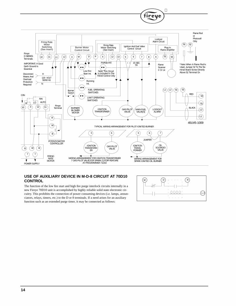
USE OF AUXILIARY DEVICE IN M-D-8 CIRCUIT AT 70D10 CONTROLThe function of the low fire start and high fire purge interlock circuits internally in a new Fireye 70D10 unit is accomplished by highly reliable solid state electronic cir-cuitry. This prohibits the connection of power consuming devices (i.e. lamps, annun-ciators, relays, timers, etc.) to the D or 8 terminals. If a need arises for an auxiliary function such as an extended purge timer, it may be connected as follows:
M D R
L 2
14
®
INSTALLATION TESTINGTo test the Series D10-20 controls for flame signal, a 1,000 ohm/volt (or greater) DC voltmeter or aDigital meter with input impedance of 500K ohms or greater, should be used, set on a scale to readthe following test voltages:
Flame Signal DC Test VoltageDrop Out Normal5 volts 20-25 volts
Note: The Fireye 45UV5-1009 is a repetitive self-check scanner that contains a highly reliable shut-ter that closes every 4 seconds to initiate a system check. When the shutter closes, the test jack volt-age should go down to approximately zero, and then back to the normal reading in about 2 seconds.To assure sufficient flame signal margin to hold in the flame relay during random momentary down-ward fluctuations of flame signal, it is recommended that a signal close to normal be obtained. Theleads from the test meter plug into the red and black test jacks on the amplifier (red + black -).
Normal Pilot Flame Test
Caution: Before making a pilot flame test, manually shut off the fuel supply to the main burner.
1. Place the “check-run” switch on the programmer in the “check” position. A small tool such as ascrewdriver is required. Turn power on and initiate a normal start-up.
2. Observe the pilot flame signal on the test meter. If the average voltage is below normal, readjustthe pilot flame or realign the detector.
3. During the pilot flame test and adjustment period, if flame is not detected the control will lock-out. To reestablish the pilot flame trial for ignition (TFI), manual reset of the lock- out switch isrequired, and a complete repurge accomplished.
4. When UV flame detection is used, a test is required to verify that UV radiation from the ignitionspark is not being detected. To accomplish this, manually shut off both pilot and main fuels. Ini-tiate a normal start-up and when the TFI light comes on, observe the test meter which shouldread no more than I volt. If more than I volt is observed realign the UV scanner, and/or shieldthe spark from the scanner's view. Programmer 71D70 provides for ignition spark cutoff prior topilot flame proving when the ignition transformer is connected to Terminal 5 to assist withinstallations where UV radiation from spark ignition is difficult to eliminate from the view ofthe UV scanner.
5. With all methods of flame detection, check Pilot flame failure response by manually shutting offthe pilot fuel and then initiate a normal start-up. With no Pilot flame present, the control willdeenergize the pilot assembly at the end of the trial for ignition interval, and the control willlockout. The “check-run” switch must be in the “run” position for this test.
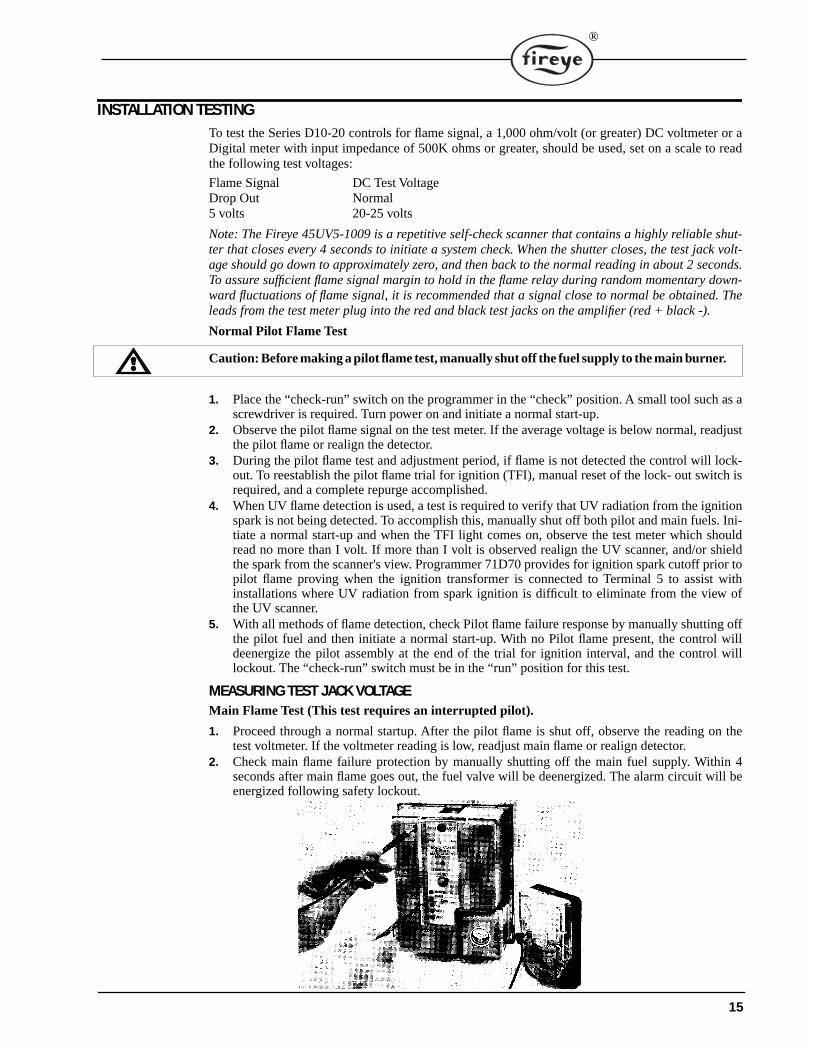
MEASURING TEST JACK VOLTAGEMain Flame Test (This test requires an interrupted pilot).
1. Proceed through a normal startup. After the pilot flame is shut off, observe the reading on thetest voltmeter. If the voltmeter reading is low, readjust main flame or realign detector.
2. Check main flame failure protection by manually shutting off the main fuel supply. Within 4seconds after main flame goes out, the fuel valve will be deenergized. The alarm circuit will beenergized following safety lockout.
15
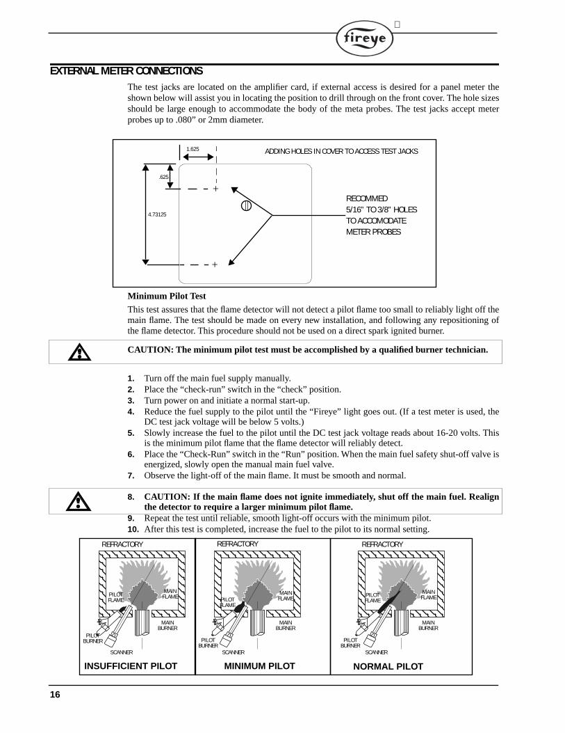
EXTERNAL METER CONNECTIONSThe test jacks are located on the amplifier card, if external access is desired for a panel meter theshown below will assist you in locating the position to drill through on the front cover. The hole sizesshould be large enough to accommodate the body of the meta probes. The test jacks accept meterprobes up to .080” or 2mm diameter.
Minimum Pilot Test
This test assures that the flame detector will not detect a pilot flame too small to reliably light off themain flame. The test should be made on every new installation, and following any repositioning ofthe flame detector. This procedure should not be used on a direct spark ignited burner.
CAUTION: The minimum pilot test must be accomplished by a qualified burner technician.
1. Turn off the main fuel supply manually.2. Place the “check-run” switch in the “check” position.3. Turn power on and initiate a normal start-up.4. Reduce the fuel supply to the pilot until the “Fireye” light goes out. (If a test meter is used, the
DC test jack voltage will be below 5 volts.)5. Slowly increase the fuel to the pilot until the DC test jack voltage reads about 16-20 volts. This
is the minimum pilot flame that the flame detector will reliably detect.6. Place the “Check-Run” switch in the “Run” position. When the main fuel safety shut-off valve is
energized, slowly open the manual main fuel valve.7. Observe the light-off of the main flame. It must be smooth and normal.
8. CAUTION: If the main flame does not ignite immediately, shut off the main fuel. Realignthe detector to require a larger minimum pilot flame.
9. Repeat the test until reliable, smooth light-off occurs with the minimum pilot.10. After this test is completed, increase the fuel to the pilot to its normal setting.
RECOMMED5/16” TO 3/8” HOLESTO ACCOMODATE METER PROBES
1.625
4.73125
.625
ADDING HOLES IN COVER TO ACCESS TEST JACKS
+
+
MAINFLAME
REFRACTORY
MAINBURNER
PILOTFLAME
SCANNER
PILOTBURNER
INSUFFICIENT PILOT
MAINFLAME
REFRACTORY
MAINBURNER
PILOTFLAME
SCANNER
PILOTBURNER
MINIMUM PILOT
MAINFLAME
REFRACTORY
MAINBURNER
PILOTFLAME
SCANNER
PILOTBURNER
NORMAL PILOT
16
®
Test for Incandescent Refractory Hold-ln With Photocell DetectorType 45CM I Photocell Scanners are actuated by light energy. To assure that the flame failureresponse time is not extended by radiation from incandescent refractory, the following test is recom-mended:
1. Operate the burner, following the burner manufacturer's instructions, until the refractory is atmaximum operating temperature.
2. Turn off the main fuel supply manually.3. Observe the “Fireye” light (LED), which must go out within 4 seconds.4. If the flame failure response time exceeds 4 seconds, reduce the amount of light at the Photocell
with a screen, an orifice or a filter lens, until the normal flame failure response is obtained.
Operational TestWhen the installation and all burner adjustments are completed, the entire burner control systemshould be tested in accordance with the burner manufacturer's instructions. The procedure shouldverify the correct operation of:
1. Each operating control (temperature, pressure etc.).2. Each limit switch (temperature, pressure, low water cut- off, etc.).3. Each interlock switch (air-flow switch, high and low fuel pressure or temperature switches,
purge and low fire start switches, fuel valve proof of closure interlock, etc.).4. Pilot flame failure response and lockout.5. Main flame failure response and lockout.6. Tight shutoff of all fuel valves.
Note: Before attempting to reset the lockout switch, wait approximately 2 minutes for the lockoutswitch heater to cool.
SERVICING
Caution: Only trained and qualified Safety Control Technicians should attempt to serviceFlame Safeguard Control installations. Special care must be exercised in troubleshooting aburner control system. Electrically live parts are exposed when covers of devices are removed.Additionally, safety interlocks and limit switches (air flow, fuel pressure, LWCO, etc.) shouldnot be jumpered out during troubleshooting, nor should any attempt be made to eliminateor alter any portion of the programming sequence beyond use of the “Run-check” switchduring the pilot “trial for ignition” period of pilot ignited burners.
Servicing of Fireye D Series units is facilitated by the use of Plug-in Programmer and Amplifiermodules. Trouble with installations equipped with Fireye 70D10, 70D20 Controls can be readily iso-lated by following the procedure in the sequence listed below. An AC-DC test meter is required. Testpoints are located on the chassis board to assist with measuring line and load voltages (150 volt ACscale).
Before beginning any troubleshooting, make sure that:
1. Installation and wiring have been made in accordance with the installation instructions.2. Contact tabs on bottom of chassis are not bent out of position.3. Chassis is properly secured to the wiring base.4. The programmer is securely plugged in and the “Run- Check” switch is in the “Run” position.5. The correct amplifier for the method of flame detection desired is securely plugged in6. The flame detector is clean.7. The lockout switch is reset.
17
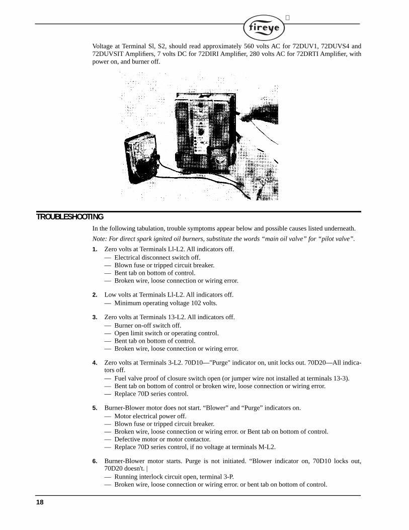
Voltage at Terminal Sl, S2, should read approximately 560 volts AC for 72DUV1, 72DUVS4 and72DUVSIT Amplifiers, 7 volts DC for 72DIRI Amplifier, 280 volts AC for 72DRTI Amplifier, withpower on, and burner off.
TROUBLESHOOTINGIn the following tabulation, trouble symptoms appear below and possible causes listed underneath.
Note: For direct spark ignited oil burners, substitute the words “main oil valve” for “pilot valve”.
1. Zero volts at Terminals Ll-L2. All indicators off.— Electrical disconnect switch off.— Blown fuse or tripped circuit breaker.— Bent tab on bottom of control.— Broken wire, loose connection or wiring error.
2. Low volts at Terminals Ll-L2. All indicators off.— Minimum operating voltage 102 volts.
3. Zero volts at Terminals 13-L2. All indicators off.— Burner on-off switch off.— Open limit switch or operating control.— Bent tab on bottom of control.— Broken wire, loose connection or wiring error.
4. Zero volts at Terminals 3-L2. 70D10—"Purge" indicator on, unit locks out. 70D20—All indica-tors off.— Fuel valve proof of closure switch open (or jumper wire not installed at terminals 13-3).— Bent tab on bottom of control or broken wire, loose connection or wiring error.— Replace 70D series control.
5. Burner-Blower motor does not start. “Blower” and “Purge” indicators on.— Motor electrical power off.— Blown fuse or tripped circuit breaker.— Broken wire, loose connection or wiring error. or Bent tab on bottom of control.— Defective motor or motor contactor.— Replace 70D series control, if no voltage at terminals M-L2.
6. Burner-Blower motor starts. Purge is not initiated. “Blower indicator on, 70D10 locks out,70D20 doesn't. |— Running interlock circuit open, terminal 3-P.— Broken wire, loose connection or wiring error. or bent tab on bottom of control.
18
®
— Replace 70D series control.
7. Burner-Blower motor runs, control locks out “Blower”, “Purge”, “Fireye” indicators on.— Flame scanner is detecting actual flame.— Replace flame scanner or correct scanner wiring.— Replace 72 series amplifier module. or replace 70D series control.
8. Firing rate motor does not drive to high fire. “Blower” and “Purge” indicators on.— Firing rate motor not powered or defective.— Linkage jammed.— Broken wire, loose connection or wiring error. or bent tab on bottom of control.— Replace 71D series programmer module. or replace 70D series control.
9. Firing rate motor drives to high fire position, and stays there forever. “Blower” and purge indica-tor on.— 70D10—Purge interlock circuit (High fire) not closed, Terminals D-8.— Linkage jammed.— Broken wire, loose connection or wiring error.— Bent tab on bottom of control.— Replace 71D series programmer module. or replace 70D series control.
Note: Test the Low Fire Interlock (M to D) and purge interlock (D to 8) on a 70D10 control installa-tion with an AC voltmeter as follows. The burner blower must be operating. Measure D to L2 andwith Low Fire Interlock closed obtain 120 V; with L.F.I. open obtain 30 to 42 VAC.Measure 8 to L2and with Hi Fire Interlock switch closed obtain 30 to 120 VAC and with H.F.I. open obtain 0 VAC.
10. Firing rate motor returns to low fire, pilot ignition (Terminals 5, 6) not powered after short delay.“Blower” indicator on.— Low fire start interlock not closed, Terminals M-D.— Bent tab on bottom of control.— Replace 71D60 programmer module. or replace 70D series control.
11. Pilot ignition Terminals 5-6 powered momentarily and then control locks out. “Blower,” “TFI”indicators on. — Replace 70D series control.
12. Pilot flame not established. “Blower” and “TFI” indicators on, “Fireye” indicator off.— Defective pilot valve, ignition transformer, electrode or adjustment.— Improper gas pressure or burner adjustment.— Broken wire, loose connection or wiring error.— Bent tab on bottom of control.— Replace 70D series control.
13. Pilot flame lights, but is not detected. “Blower” and “TFI” indicators on, “Fireye” indicator off.(No test jack voltage) — Scanner does not see adequate pilot flame.— Broken wire, loose connection or wiring error.— Bent tab on bottom of control.— Replace 72 series amplifier module. or replace flame scanner.— With UV units, remove factory installed grounding wire (if present) from Terminal S2 on the
wiring base.
14. Main flame not established following 10 second pilot |flame “TFI.” “Blower” and “Fireye” indi-cators on.— “Run-check” switch in “check” position.— Inadequate main fuel supply. or defective main fuel valve.— Main burner improperly adjusted.— Broken wire, loose connection or wiring error. or bent tab on bottom of control.— Replace 70D series control.
19
15. Main flame lights and then goes out. “Blower” indicator on.— Main flame and pilot blow out.— Limit operating control circuit (Terminals L 1-3) or running interlock circuit (Terminals 3-
P) opens momentarily.
Note: 70D10, if running interlock circuit opens, control will lock out. 70D20, if running interlockcircuit opens, control will recycle.
16. Main flame lights normally, but goes out when pilot flame is shut off. “Blower,” “Fireye,”“Auto” indicators on.— Gas pilot valve stuck open.— Wiring error.— Replace 70D series control.
17. Firing rate motor does not respond to demand at end of main flame “TFI”. “Blower,” “Fireye,”“Auto” indicators on— Potentiometer controller set too low or in manual mode.— Broken wire, loose connection or wiring error.— Bent tab on bottom of control.— Replace 71D series programmer. or replace 70D series control.
18. Flame signal drops off while main burner is firing and modulating. “Blower”, “Auto” indicatorson. “Fireye” indicators off.— Burner is not properly adjusted.— Flame scanner loses sight of flame.— Control and/or flame scanner subjected to excessive temperature.
19. Main fuel valve does not close when operating control opens. “Blower, “Fireye” indicators on.— Main fuel valve stuck open.— Wiring error.
20. During post purge period, firing rate motor does not drive to low fire position. “Blower” indica-tor on.— Firing rate motor not powered or defective.— Linkage jammed.— Broken wire, loose connection, wiring error.— Bent tab on bottom of control.— Replace 70D series control.
21. Burner, Blower motor does not stop following postpurge period. All indicators off.— Motor contactor defective.— Wiring error.
Note: If operating control recloses during the post purge period, a complete restart is initiated. Donot momentarily depress the lockout reset button to recycle the unit, as it will cause some units tolockout. Open and reclose the burner control switch instead.
20
®
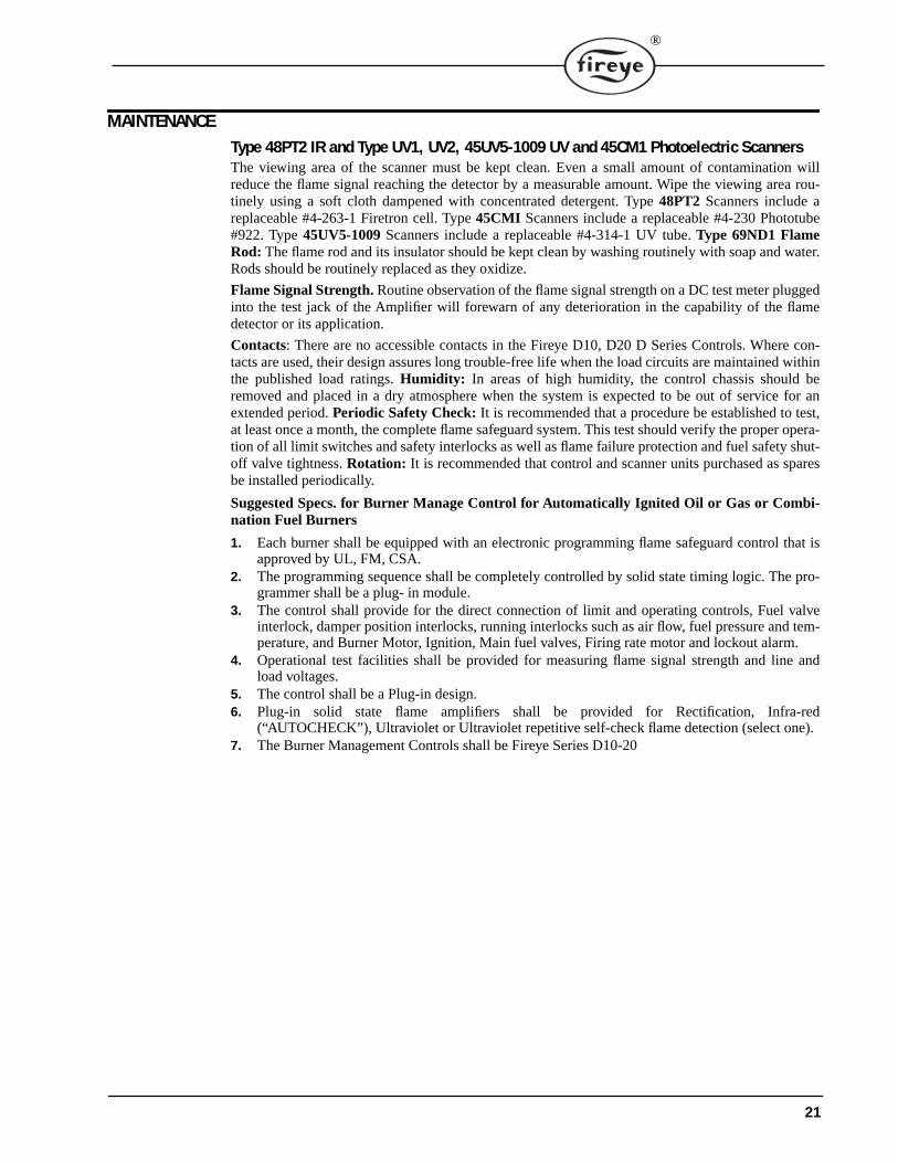
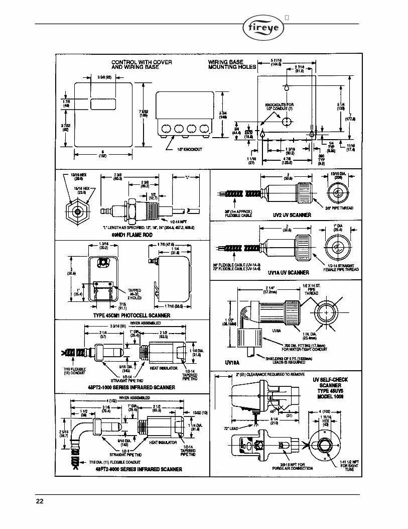
MAINTENANCEType 48PT2 IR and Type UV1, UV2, 45UV5-1009 UV and 45CM1 Photoelectric ScannersThe viewing area of the scanner must be kept clean. Even a small amount of contamination willreduce the flame signal reaching the detector by a measurable amount. Wipe the viewing area rou-tinely using a soft cloth dampened with concentrated detergent. Type 48PT2 Scanners include areplaceable #4-263-1 Firetron cell. Type 45CMI Scanners include a replaceable #4-230 Phototube#922. Type 45UV5-1009 Scanners include a replaceable #4-314-1 UV tube. Type 69ND1 FlameRod: The flame rod and its insulator should be kept clean by washing routinely with soap and water.Rods should be routinely replaced as they oxidize.
Flame Signal Strength. Routine observation of the flame signal strength on a DC test meter pluggedinto the test jack of the Amplifier will forewarn of any deterioration in the capability of the flamedetector or its application.
Contacts: There are no accessible contacts in the Fireye D10, D20 D Series Controls. Where con-tacts are used, their design assures long trouble-free life when the load circuits are maintained withinthe published load ratings. Humidity: In areas of high humidity, the control chassis should beremoved and placed in a dry atmosphere when the system is expected to be out of service for anextended period. Periodic Safety Check: It is recommended that a procedure be established to test,at least once a month, the complete flame safeguard system. This test should verify the proper opera-tion of all limit switches and safety interlocks as well as flame failure protection and fuel safety shut-off valve tightness. Rotation: It is recommended that control and scanner units purchased as sparesbe installed periodically.
Suggested Specs. for Burner Manage Control for Automatically Ignited Oil or Gas or Combi-nation Fuel Burners
1. Each burner shall be equipped with an electronic programming flame safeguard control that isapproved by UL, FM, CSA.
2. The programming sequence shall be completely controlled by solid state timing logic. The pro-grammer shall be a plug- in module.
3. The control shall provide for the direct connection of limit and operating controls, Fuel valveinterlock, damper position interlocks, running interlocks such as air flow, fuel pressure and tem-perature, and Burner Motor, Ignition, Main fuel valves, Firing rate motor and lockout alarm.
4. Operational test facilities shall be provided for measuring flame signal strength and line andload voltages.
5. The control shall be a Plug-in design.6. Plug-in solid state flame amplifiers shall be provided for Rectification, Infra-red
(“AUTOCHECK”), Ultraviolet or Ultraviolet repetitive self-check flame detection (select one).7. The Burner Management Controls shall be Fireye Series D10-20
21
22

®
23

24
®
NOTICEWhen Fireye products are combined with equipment manufactured by others and/or integrated intosystems designed or manufactured by others, the Fireye warranty, as stated in its General Terms andConditions of Sale, pertains only to the Fireye products and not to any other equipment or to thecombined system or its overall performance.
WARRANTIESFIREYE guarantees for one year from the date of installation or 18 months from date of manufactureof its products to replace, or, at its option, to repair any product or part thereof (except lamps, elec-tronic tubes and photocells) which is found defective in material or workmanship or which otherwisefails to conform to the description of the product on the face of its sales order. THE FOREGOINGIS IN LIEU OF ALL OTHER WARRANTIES AND FIREYE MAKES NO WARRANTY OFMERCHANTABILITY OR ANY OTHER WARRANTY, EXPRESS OR IMPLIED. Except asspecifically stated in these general terms and conditions of sale, remedies with respect to any productor part number manufactured or sold by Fireye shall be limited exclusively to the right to replace-ment or repair as above provided. In no event shall Fireye be liable for consequential or special dam-ages of any nature that may arise in connection with such product or part.
FIREYE D-10203 Manchester Road MARCH 2001Derry, New Hampshire 03038 USA Supersedes Jan. 1994www.Fireye.com
25