Embed Size (px)
Citation preview

750-36607/2013
Hawk 1000Boiler Control
Operation Manual

TO: Owners, Operators and/or Maintenance Personnel
This operating manual presents information that will help to properly operate and care for the equipment. Study its con-tents carefully. The unit will provide good service and continued operation if proper operating and maintenance instruc-tions are followed. No attempt should be made to operate the unit until the principles of operation and all of the components are thoroughly understood.
It is the responsibility of the owner to train and advise not only his or her personnel, but the contractors' personnel who are servicing, repairing, or operating the equipment, in all safety aspects.
Cleaver-Brooks equipment is designed and engineered to give long life and excellent service on the job. The electrical and mechanical devices supplied as part of the unit were chosen because of their known ability to perform; however, proper operating techniques and maintenance procedures must be followed at all times.
Any "automatic" features included in the design do not relieve the attendant of any responsibility. Such features merely free him of certain repetitive chores and give him more time to devote to the proper upkeep of equipment.
It is solely the operator’s responsibility to properly operate and maintain the equipment. No amount of written instruc-tions can replace intelligent thinking and reasoning and this manual is not intended to relieve the operating personnel of the responsibility for proper operation. On the other hand, a thorough understanding of this manual is required before attempting to operate, maintain, service, or repair this equipment.
Operating controls will normally function for long periods of time and we have found that some operators become lax in their daily or monthly testing, assuming that normal operation will continue indefinitely. Malfunctions of controls lead to uneconomical operation and damage and, in most cases, these conditions can be traced directly to carelessness and deficiencies in testing and maintenance.
The operation of this equipment by the owner and his operating personnel must comply with all requirements or regula-tions of his insurance company and/or other authority having jurisdiction. In the event of any conflict or inconsistency between such requirements and the warnings or instructions contained herein, please contact Cleaver-Brooks before pro-ceeding.
Cleaver-BrooksHAWK 1000 Boiler Control
Operation Manual
Manual Part No. 750-36607/2013
Please direct purchase orders for replacement manuals to your local Cleaver-Brooks authorized representative

CONTENTS
Section 1General
Introduction .................................................................................. 1-2System Description ........................................................................ 1-3Hawk 1000 System Features .......................................................... 1-4Safety Provisions and Diagnostics .................................................... 1-5Inputs and Outputs ......................................................................... 1-6
Section 2System Components
Overview ......................................................................................2-2Controller ......................................................................................2-2Human-Machine Interface (HMI) .....................................................2-3Communications ............................................................................2-4Sensor Inputs ................................................................................2-6
Section 3Hardware Checkout
Control Panel Component Checks ....................................................3-2Modbus Actuator Checks ................................................................3-7
Section 4System Configuration
Introduction .................................................................................4-2Main Menu ..................................................................................4-2Boiler Overview ............................................................................4-3System Configuration ....................................................................4-4
Section 5Commissioning
Commissioning the Actuators . . . . . . . . . . . . . . . . . . . . . . . . . . . . . 5-2Setting Combustion - Parallel Positioning . . . . . . . . . . . . . . . . . . . . . 5-4Setting Combustion - Single Point Positioning . . . . . . . . . . . . . . . . . . 5-8Setting Combustion - Low/High/Low. . . . . . . . . . . . . . . . . . . . . . . . . 5-8Firing Rate Screen . . . . . . . . . . . . . . . . . . . . . . . . . . . . . . . . . . . . . 5-9Alarms and Limits . . . . . . . . . . . . . . . . . . . . . . . . . . . . . . . . . . . . . 5-11Setpoints . . . . . . . . . . . . . . . . . . . . . . . . . . . . . . . . . . . . . . . . . . . 5-13O2 Trim . . . . . . . . . . . . . . . . . . . . . . . . . . . . . . . . . . . . . . . . . . . . 5-15Drive Data . . . . . . . . . . . . . . . . . . . . . . . . . . . . . . . . . . . . . . . . . . 5-16Ethernet Configuration . . . . . . . . . . . . . . . . . . . . . . . . . . . . . . . . . . 5-16Two Boiler Lead Lag . . . . . . . . . . . . . . . . . . . . . . . . . . . . . . . . . . . 5-17Thermal Shock Routine . . . . . . . . . . . . . . . . . . . . . . . . . . . . . . . . . 5-18
Section 6Diagnostics and Troubleshooting
System Monitoring and Diagnostics . . . . . . . . . . . . . . . . . . . . . . . . . 6-2PLC Status . . . . . . . . . . . . . . . . . . . . . . . . . . . . . . . . . . . . . . . . . . 6-4
Section 7Parts
Hawk 1000 Parts List . . . . . . . . . . . . . . . . . . . . . . . . . . . . . . . . . . 7-1

www.cleaverbrooks.com
Section 1General
Introduction . . . . . . . . . . . . . . . . . . . . . . . . . . . . . . . . . . . . . . . . . . . . . . . . 1-2System Description . . . . . . . . . . . . . . . . . . . . . . . . . . . . . . . . . . . . . . . . . . . 1-3Hawk 1000 System Features . . . . . . . . . . . . . . . . . . . . . . . . . . . . . . . . . . . . 1-4Safety Provisions and Diagnostics . . . . . . . . . . . . . . . . . . . . . . . . . . . . . . . . . 1-5
Burner Management . . . . . . . . . . . . . . . . . . . . . . . . . . . . . . . . . . . 1-5Boiler Controls . . . . . . . . . . . . . . . . . . . . . . . . . . . . . . . . . . . . . . . . 1-5
Inputs and Outputs. . . . . . . . . . . . . . . . . . . . . . . . . . . . . . . . . . . . . . . . . . . . 1-6
Section 1 — General Hawk 1000
1.1 Introduction
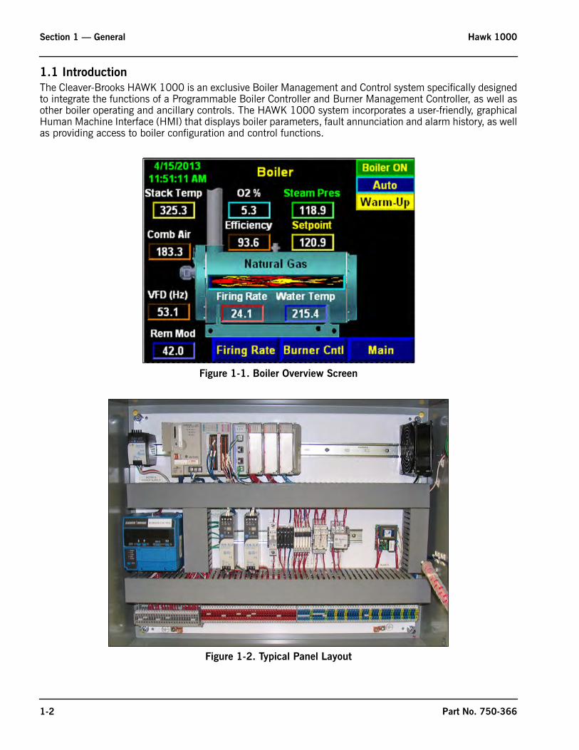
The Cleaver-Brooks HAWK 1000 is an exclusive Boiler Management and Control system specifically designedto integrate the functions of a Programmable Boiler Controller and Burner Management Controller, as well asother boiler operating and ancillary controls. The HAWK 1000 system incorporates a user-friendly, graphicalHuman Machine Interface (HMI) that displays boiler parameters, fault annunciation and alarm history, as wellas providing access to boiler configuration and control functions.
Figure 1-1. Boiler Overview Screen
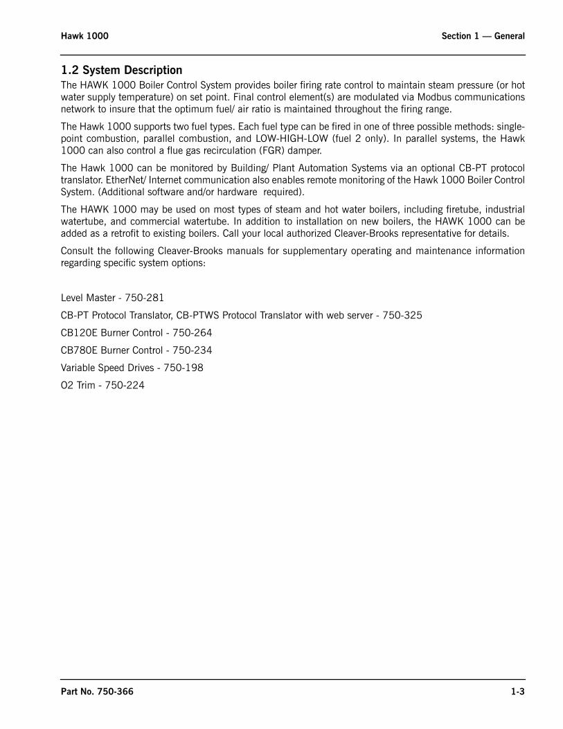
Figure 1-2. Typical Panel Layout
1-2 Part No. 750-366
Hawk 1000 Section 1 — General
1.2 System Description
The HAWK 1000 Boiler Control System provides boiler firing rate control to maintain steam pressure (or hotwater supply temperature) on set point. Final control element(s) are modulated via Modbus communicationsnetwork to insure that the optimum fuel/ air ratio is maintained throughout the firing range.
The Hawk 1000 supports two fuel types. Each fuel type can be fired in one of three possible methods: single-point combustion, parallel combustion, and LOW-HIGH-LOW (fuel 2 only). In parallel systems, the Hawk1000 can also control a flue gas recirculation (FGR) damper.
The Hawk 1000 can be monitored by Building/ Plant Automation Systems via an optional CB-PT protocoltranslator. EtherNet/ Internet communication also enables remote monitoring of the Hawk 1000 Boiler ControlSystem. (Additional software and/or hardware required).
The HAWK 1000 may be used on most types of steam and hot water boilers, including firetube, industrialwatertube, and commercial watertube. In addition to installation on new boilers, the HAWK 1000 can beadded as a retrofit to existing boilers. Call your local authorized Cleaver-Brooks representative for details.
Consult the following Cleaver-Brooks manuals for supplementary operating and maintenance informationregarding specific system options:
Level Master - 750-281
CB-PT Protocol Translator, CB-PTWS Protocol Translator with web server - 750-325
CB120E Burner Control - 750-264
CB780E Burner Control - 750-234
Variable Speed Drives - 750-198
O2 Trim - 750-224
Part No. 750-366 1-3
Section 1 — General Hawk 1000
1.3 Hawk 1000 System Features
• Burner Control controls burner start and shutdown sequencing and flame and interlock monitoring• Compatible with CB780E and CB120E Burner Controls and Flame Scanners• Boiler Control monitors and displays connected boiler parameters (operating pressure or temperature, stack
temperature, shell water temperature, O2% etc.)• 4" color touch/keypad Human Machine Interface (HMI)• Optimized boiler firing rate control• Alarm/Fault Indication and History -- first out annunciation with time stamp and displayed in order of fault
occurrence• Dual set point capability• Thermal shock protection (includes warm-up routine, low fire hold & hot stand-by operation)• Available input for any ONE of the following: remote modulation, remote set point, or Level Master water level
interface• Available input for any ONE of the following: water temp (Steam)• Return Temp or Outdoor reset (hot water boilers)• Remote Modulation by communications (EtherNet)• Remote Set Point by communications (EtherNet)• Boiler efficiency calculation• Assured Low Fire Cut Off• External Interlock with auxiliary devices (fresh air damper/louvers, circulating pumps, etc.)• High stack temperature alarm and shutdown• Built-in two-boiler lead/lag capability (local set point only)• EtherNet communications• Three firing modes: Single-point, parallel, or LOW-HIGH-LOW• Revert to Pilot control function (requires CB120E burner control)• Supports control of a flue gas recirculation (FGR) damper• Supports the control of a 2nd gaseous fuel actuator (Both Gaseous Fuels)• OPC server software for building/plant automation system interface• Remote monitoring software• O2 monitoring and O2 trim (Option)• Variable Speed Drive on combustion air fan (with bypass) (Option)• Combustion Air Temperature Monitoring (Option)
1-4 Part No. 750-366
Hawk 1000 Section 1 — General
1.4 Safety Provisions and Diagnostics
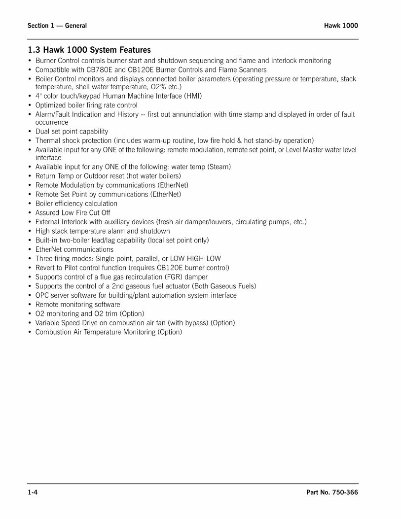
1.4.1 Burner Management• Utilizes CB780E or CB120E Burner Control• Communicates with the PLC via Modbus• Burner Control Status, Faults and Diagnostics displayed on HMI or panel mounted burner control• Flame condition monitoring using either IR or UV Flame Scanner
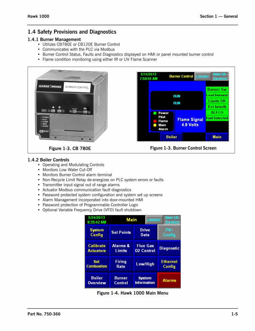
1.4.2 Boiler Controls• Operating and Modulating Controls• Monitors Low Water Cut-Off• Monitors Burner Control alarm terminal• Non-Recycle Limit Relay de-energizes on PLC system errors or faults• Transmitter input signal out of range alarms• Actuator Modbus communication fault diagnostics• Password protected system configuration and system set up screens• Alarm Management incorporated into door-mounted HMI• Password protection of Programmable Controller Logic• Optional Variable Frequency Drive (VFD) fault shutdown
Figure 1-4. Hawk 1000 Main Menu
Figure 1-3. CB 780E Figure 1-3. Burner Control Screen
Part No. 750-366 1-5
Section 1 — General Hawk 1000
1-6 Part No. 750-366
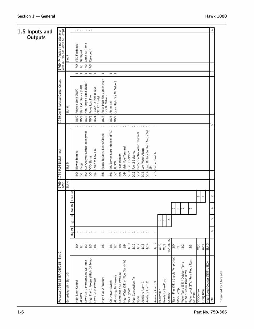
1.5 Inputs andOutputs
Proc
esso
r 1769-L
24ER
-QB
FC1
B -
Slo
t 0
1769
SM2
1769 IA
16 D
igita
l Inp
ut1769 O
W8I I
sola
ted
Dig
ital O
utpu
t1769 IF
4 A
nalo
g In
put
(Opt
iona
l w
ith O
2, VS
D o
r C
omb
Air
Tem
p)
Embe
dded
I/O
- S
lot
1-3
Slot
4Sl
ot 5
Slot
6Sl
ot 7
Dig
IND
ig O
UT
Ana
INAna
Out
Hig
h Li
mit
Con
trol
I1/0
1I5
/0B
low
er T
erm
inal
1O
6/0
Rec
ycle
Lim
it (R
LR)
1I7
/0VS
D F
eedb
ack
1
ALW
CO
I1/1
1I5
/1Pu
rge
1O
6/1
Star
t Ex
t. D
evic
e (F
AD
)1
I7/1
O2 S
igna
l1
Low
Fue
l 1 P
ress
ure/
Low
Oil
Tem
pI1
/21
I5/2
O2 A
naly
zer
Stat
us (
Yoko
gaw
a)1
O6/2
Non
-Rec
ycle
Lim
it (N
RLR
)1
I7/2
Com
b Air
Tem
p1
Hig
h Fu
el 1
Pre
ssur
e/H
igh
Oil
Tem
pI1
/31
I5/3
VSD
Sta
tus
1O
6/3
Prov
e Lo
w F
ire1
I7/3
Res
erve
d *
1
Low
Fue
l 2 P
ress
ure
I1/4
1I5
/4Fo
rce
to L
ow F
ire1
O6/4
Rev
ert
To P
ilot
(Fire
ye
CB
120E
only
) 1
Hig
h Fu
el 2
Pre
ssur
eI1
/51
I5/5
Rea
dy T
o St
art/
Lim
its C
lose
d1
O6/5
Prov
e H
igh
Fire
/ O
pen
Hig
h Fi
re O
il Va
lve
21
Oil
Dra
wer
Sw
itch
I1/6
1I5
/6Ex
t. D
evic
e St
art
Inte
rlock
(FA
D)
1O
6/6
Ala
rm B
ell
1
Ato
miz
ing
Air
Pres
sure
I1/7
1I5
/7ALF
CO
1O
6/7
Ope
n H
igh
Fire
Oil
Valv
e 1
1
Com
bust
ion
Air
Pres
sure
I1/8
1I5
/8Pi
lot
Term
inal
1
Hig
h W
ater
(ST
) or
Flo
w S
w. (H
W)
I1/9
1I5
/9M
ain
Fuel
Ter
min
al1
VSD
Byp
ass
I1/1
01
I5/1
0Fu
el 1
Sel
ecte
d1
Hig
h C
ombu
stio
n Air
I1/1
11
I5/1
1Fu
el 2
Sel
ecte
d1
Spar
eI1
/12
1I5
/12
Bur
ner
Con
trol
Ala
rm T
erm
inal
1
Aux
iliar
y Ala
rm 1
I1/1
31
I5/1
3Lo
w W
ater
Ala
rm1
Aux
iliar
y Ala
rm 2
I1/1
41
I5/1
4Le
ad B
oile
r / S
el R
em M
od /
Sel
SP1
Aux
iliar
y Ala
rm 3
I1/1
51
I5/1
5B
urne
r Sw
itch
1
Res
erve
d *
O1
/01
Rea
dy fo
r Le
ad/L
agO
1/1
1
Spar
e(s)
O1
/2-O
1/1
514
Stea
m P
res
(ST)
/ Su
pply
Tem
p (H
W)
I2/0
1
Stac
k Te
mp
I2/1
1
Wat
er T
emp
(ST)
/ O
utdo
or T
emp
(HW
) / R
etur
n Te
mp
(HW
)I2
/21
Wat
er L
evel
(ST
) / R
em M
od /
Rem
Se
t Po
int
I2/3
1
VSD
Con
trol
O2
/01
Firin
g R
ate
O2
/11
Hig
h Sp
eed
Cou
nter
(N
OT
USE
D)
Slot
3
Tota
l1
616
42
16
84
* R
eser
ved
for
futu
re a
dd
www.cleaverbrooks.com
Section 2System Components
Overview . . . . . . . . . . . . . . . . . . . . . . . . . . . . . . . . . . . . . . . . . . . . . . . . . . 2-2Base Unit . . . . . . . . . . . . . . . . . . . . . . . . . . . . . . . . . . . . . . . . . . . . . . . . . . 2-2Human-Machine Interface (HMI) . . . . . . . . . . . . . . . . . . . . . . . . . . . . . . . . . . 2-3Communications . . . . . . . . . . . . . . . . . . . . . . . . . . . . . . . . . . . . . . . . . . . . . 2-4
Modbus . . . . . . . . . . . . . . . . . . . . . . . . . . . . . . . . . . . . . . . . . . . . 2-4Ethernet . . . . . . . . . . . . . . . . . . . . . . . . . . . . . . . . . . . . . . . . . . . . 2-5USB . . . . . . . . . . . . . . . . . . . . . . . . . . . . . . . . . . . . . . . . . . . . . . 2-5
Sensor Inputs . . . . . . . . . . . . . . . . . . . . . . . . . . . . . . . . . . . . . . . . . . . . . . . 2-6Steam Systems: . . . . . . . . . . . . . . . . . . . . . . . . . . . . . . . . . . . . . . 2-6Hot Water systems: . . . . . . . . . . . . . . . . . . . . . . . . . . . . . . . . . . . . 2-6
Section 2 — System Components Hawk 1000
2-2
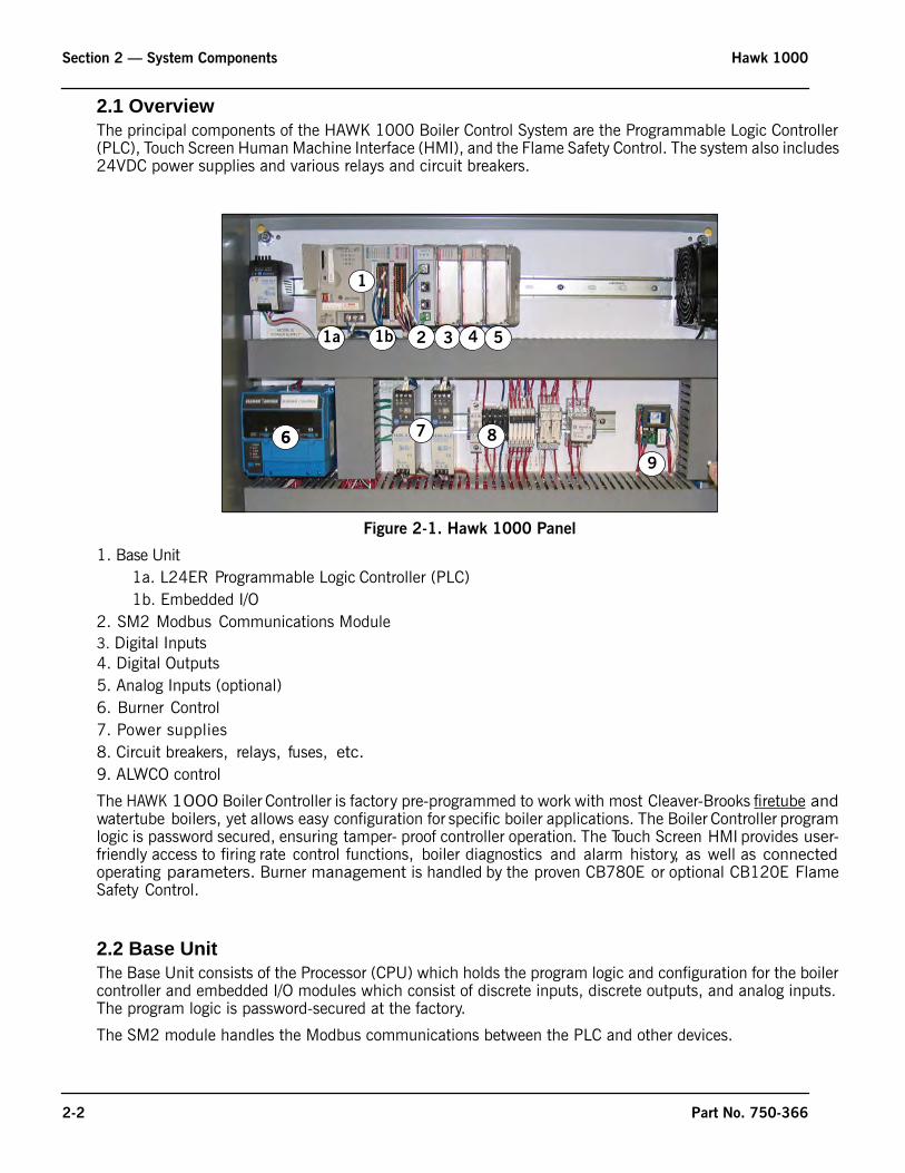
2.1 OverviewThe principal components of the HAWK 1000 Boiler Control System are the Programmable Logic Controller (PLC), Touch Screen Human Machine Interface (HMI), and the Flame Safety Control. The system also includes 24VDC power supplies and various relays and circuit breakers.
1. Base Unit1a. L24ER Programmable Logic Controller (PLC)1b. Embedded I/O
2. SM2 Modbus Communications Module3. Digital Inputs4. Digital Outputs5. Analog Inputs (optional)6. Burner Control7. Power supplies8. Circuit breakers, relays, fuses, etc.9. ALWCO control
The HAWK 1000 Boiler Controller is factory pre-programmed to work with most Cleaver-Brooks firetube and watertube boilers, yet allows easy configuration for specific boiler applications. The Boiler Controller program logic is password secured, ensuring tamper- proof controller operation. The Touch Screen HMI provides user- friendly access to firing rate control functions, boiler diagnostics and alarm history, as well as connected operating parameters. Burner management is handled by the proven CB780E or optional CB120E Flame Safety Control.
2.2 Base UnitThe Base Unit consists of the Processor (CPU) which holds the program logic and configuration for the boiler controller and embedded I/O modules which consist of discrete inputs, discrete outputs, and analog inputs. The program logic is password-secured at the factory.
The SM2 module handles the Modbus communications between the PLC and other devices.
Figure 2-1. Hawk 1000 Panel
1b 2 3 5
6 86
1
1a
7
9
4
Part No. 750-366
Hawk 1000 Section 2 — System Components
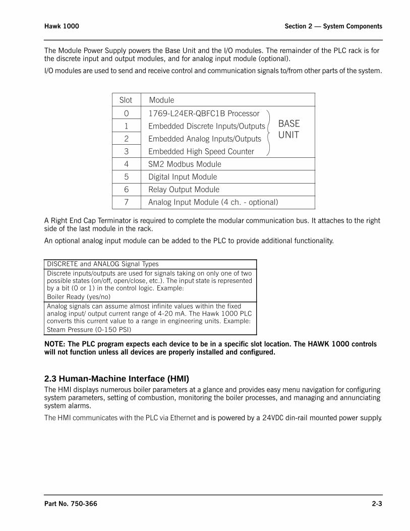
The Module Power Supply powers the Base Unit and the I/O modules. The remainder of the PLC rack is for the discrete input and output modules, and for analog input module (optional).
I/O modules are used to send and receive control and communication signals to/from other parts of the system.
A Right End Cap Terminator is required to complete the modular communication bus. It attaches to the right side of the last module in the rack.
An optional analog input module can be added to the PLC to provide additional functionality.
NOTE: The PLC program expects each device to be in a specific slot location. The HAWK 1000 controls will not function unless all devices are properly installed and configured.
2.3 Human-Machine Interface (HMI)The HMI displays numerous boiler parameters at a glance and provides easy menu navigation for configuring system parameters, setting of combustion, monitoring the boiler processes, and managing and annunciating system alarms.
The HMI communicates with the PLC via Ethernet and is powered by a 24VDC din-rail mounted power supply.
DISCRETE and ANALOG Signal TypesDiscrete inputs/outputs are used for signals taking on only one of two possible states (on/off, open/close, etc.). The input state is represented by a bit (0 or 1) in the control logic. Example:Boiler Ready (yes/no)Analog signals can assume almost infinite values within the fixed analog input/ output current range of 4-20 mA. The Hawk 1000 PLC converts this current value to a range in engineering units. Example:Steam Pressure (0-150 PSI)
Slot Module
1769-L24ER-QBFC1B Processor0
1
2
3
4
5
6
7
Embedded Discrete Inputs/Outputs
Embedded Analog Inputs/Outputs
Embedded High Speed Counter
SM2 Modbus Module
Digital Input Module
Relay Output Module
Analog Input Module (4 ch. - optional)
BASEUNIT
Part No. 750-366 2-3
Section 2 — System Components Hawk 1000
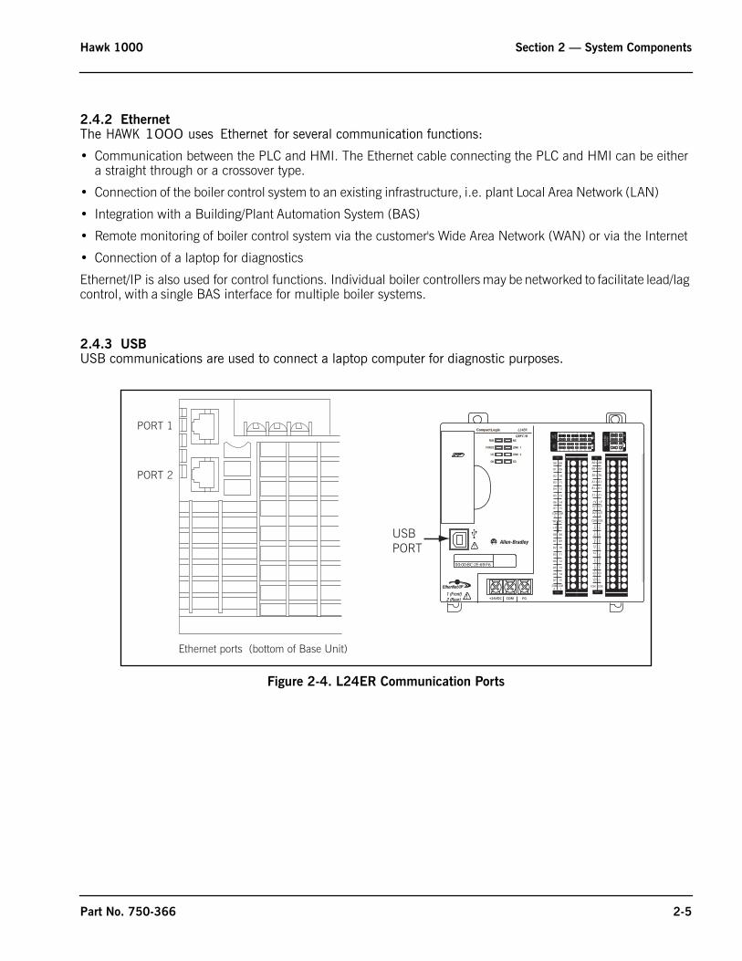
2.4 Communications2.4.1 ModbusModbus is an open serial protocol used by the HAWK 1000 system for sending and receiving control commands, position data, and diagnostic data between the PLC and attached devices. Modbus communications are managed by the SM2 module located to the right of the base unit in slot 4.
HAWK 1000 devices that communicate using Modbus include the burner flame safety control and the fuel, air, and FGR actuators. The Modbus communication network allows burner control system status and fault information to be transmitted to the PLC and displayed on the HMI screen, and in addition is used for actuator control, feedback, and fault information.
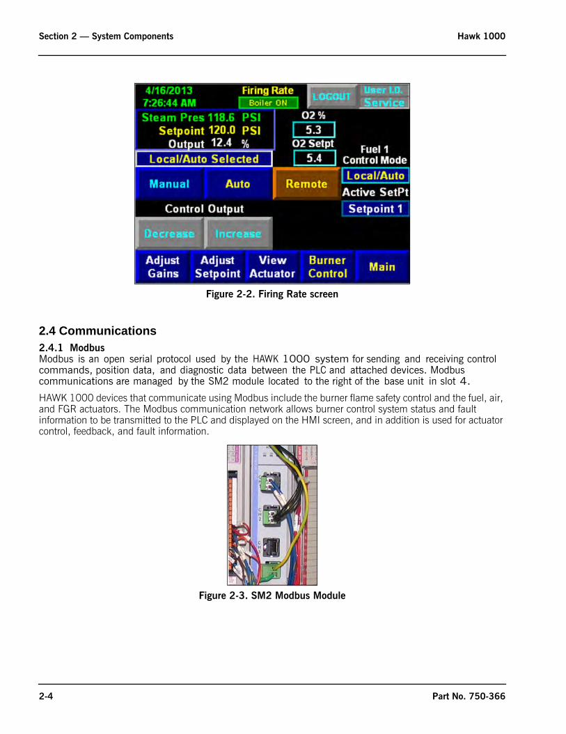
Figure 2-2. Firing Rate screen
Figure 2-3. SM2 Modbus Module
2-4 Part No. 750-366
Hawk 1000 Section 2 — System Components
2.4.2 EthernetThe HAWK 1000 uses Ethernet for several communication functions:
• Communication between the PLC and HMI. The Ethernet cable connecting the PLC and HMI can be either a straight through or a crossover type.
• Connection of the boiler control system to an existing infrastructure, i.e. plant Local Area Network (LAN)
• Integration with a Building/Plant Automation System (BAS)
• Remote monitoring of boiler control system via the customer's Wide Area Network (WAN) or via the Internet
• Connection of a laptop for diagnostics
Ethernet/IP is also used for control functions. Individual boiler controllers may be networked to facilitate lead/lag control, with a single BAS interface for multiple boiler systems.
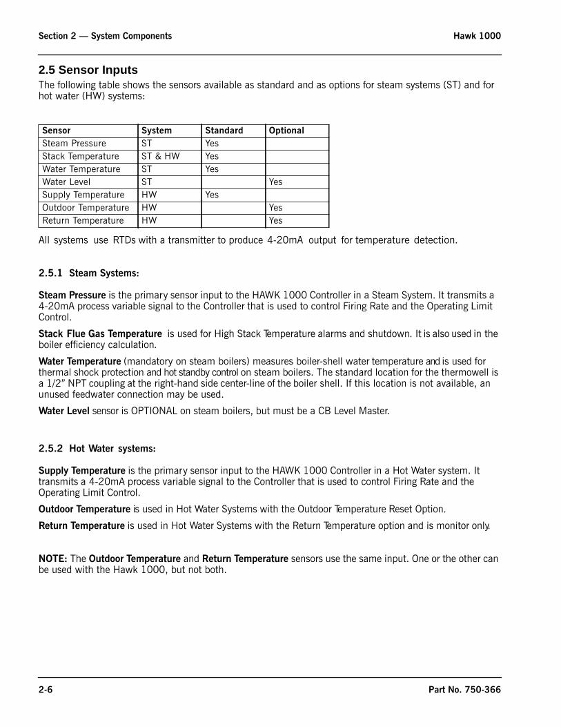
2.4.3 USBUSB communications are used to connect a laptop computer for diagnostic purposes.
Figure 2-4. L24ER Communication Ports
Ethernet ports (bottom of Base Unit)
PORT 1
PORT 2
0 1 2 3 4 5 6 7
8 9 10 11 12 13 14 15
0 1 2 3 4 5 6 7
8 9 10
A0 B0 Z0
A1 B1 Z1
0 2 FUSE
1 3 OK11 12 13 14 15
HIG
H S
PEED
COU
NTE
R
INO
UT
DC
INPU
T
24VD
CSI
NK\
SOU
RCE
24VD
CSO
URC
E
OU
TPU
TD
C
+24VDC COM FG
0 1 2 3 4 5 6 7
8 9 10 11 12 13 14 15
0 1 2 3 4 5 6 7
8 9 10
A0 B0 Z0
A1 B1 Z1
0 2 FUSE
1 3 OK11 12 13 14 15
HIG
H S
PEED
COU
NTE
R
INO
UT
DC
INPU
T
24VD
CSI
NK\
SOU
RCE
24VD
CSO
URC
E
OU
TPU
TD
C
+24VDC COM FG
00
01
02
03
04
05
06
07
NC
+V
00
01
02
03
04
05
06
07
COM0
COM0
08
09
10
11
12
13
14
15
NC
+V
08
09
10
11
12
13
14
15
COM1
COM1
A0+
B0+
Z0+
A1+
B1+
Z1+
+V
OUT1
OUT0
COM COM
A0-
B0-
Z0-
A1-
B1-
Z1-
+V
0UT3
Vin0+
Vin2+
VOUT0+I
OUT0+
VOUT1+
Iin3+
Vin1+Iin1+
Iin1+
Vin3+
CJC-
CJC+
V/Iin1-
V/Iin3-
V/Iin0-
V/Iin2-
Iin0+
Iin2+
OUT2
COMCOM
DC IN HSC
DC OUT ANALOG
00:00:BC:2E:69:F6
L24ER
QBFC1B
USBPORT
Part No. 750-366 2-5
Section 2 — System Components Hawk 1000
2.5 Sensor InputsThe following table shows the sensors available as standard and as options for steam systems (ST) and for hot water (HW) systems:
All systems use RTDs with a transmitter to produce 4-20mA output for temperature detection.
2.5.1 Steam Systems:
Steam Pressure is the primary sensor input to the HAWK 1000 Controller in a Steam System. It transmits a 4-20mA process variable signal to the Controller that is used to control Firing Rate and the Operating Limit Control.
Stack Flue Gas Temperature is used for High Stack Temperature alarms and shutdown. It is also used in the boiler efficiency calculation.
Water Temperature (mandatory on steam boilers) measures boiler-shell water temperature and is used for thermal shock protection and hot standby control on steam boilers. The standard location for the thermowell is a 1/2” NPT coupling at the right-hand side center-line of the boiler shell. If this location is not available, an unused feedwater connection may be used.
Water Level sensor is OPTIONAL on steam boilers, but must be a CB Level Master.
2.5.2 Hot Water systems:
Supply Temperature is the primary sensor input to the HAWK 1000 Controller in a Hot Water system. It transmits a 4-20mA process variable signal to the Controller that is used to control Firing Rate and the Operating Limit Control.
Outdoor Temperature is used in Hot Water Systems with the Outdoor Temperature Reset Option.
Return Temperature is used in Hot Water Systems with the Return Temperature option and is monitor only.
NOTE: The Outdoor Temperature and Return Temperature sensors use the same input. One or the other can be used with the Hawk 1000, but not both.
Sensor System Standard Optional
Steam Pressure ST YesStack Temperature ST & HW YesWater Temperature ST YesWater Level ST YesSupply Temperature HW YesOutdoor Temperature HW YesReturn Temperature HW Yes
2-6 Part No. 750-366
www.cleaverbrooks.com
Section 3Hardware Checkout
Control Panel Component Checks . . . . . . . . . . . . . . . . . . . . . . . . . . . . . . 3-2DIN Rail Latch and Expansion I/O Module Locking Levers . . . . . . 3-2Panel and Field Wiring Terminations . . . . . . . . . . . . . . . . . . . . . 3-3SM2 Module DIP Switch . . . . . . . . . . . . . . . . . . . . . . . . . . . . . 3-3Burner Control Modbus Address and Baud Rate - CB780E . . . . . 3-4Burner Control Modbus Address and Baud Rate - CB120E . . . . . 3-6PLC Switch . . . . . . . . . . . . . . . . . . . . . . . . . . . . . . . . . . . . . . 3-7
Modbus Actuator Checks . . . . . . . . . . . . . . . . . . . . . . . . . . . . . . . . . . . . 3-7Mounting . . . . . . . . . . . . . . . . . . . . . . . . . . . . . . . . . . . . . . . . 3-7Electrical Connections . . . . . . . . . . . . . . . . . . . . . . . . . . . . . . . 3-7Setting The Modbus Node Address . . . . . . . . . . . . . . . . . . . . . . 3-9Power/ Communications LED . . . . . . . . . . . . . . . . . . . . . . . . . . 3-10Moving The Actuator . . . . . . . . . . . . . . . . . . . . . . . . . . . . . . . . 3-11
Section 3 — Hardware Checkout Hawk 1000
3.1 Control Panel Component Checks
This section will cover the initial system checkout to be done prior to configuring and commissioning the system through the HMI menu system.
It is necessary to confirm that all of the integral components and interconnecting wiring are in place and secure. Vibration and jarring from transport or installation may have loosened components or wiring terminals. It is good practice to check all system components for integrity and tightness prior to initial power-up of the system. Any external interlock and remote signal wiring should also be connected to the boiler controller.
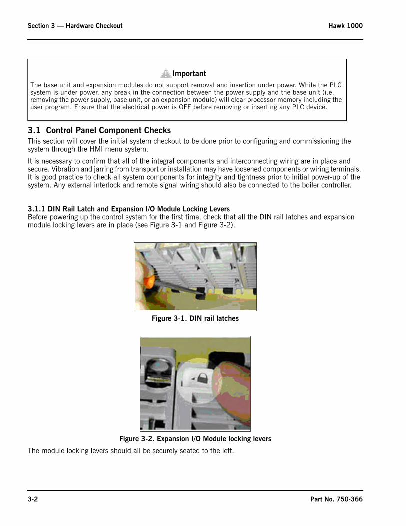
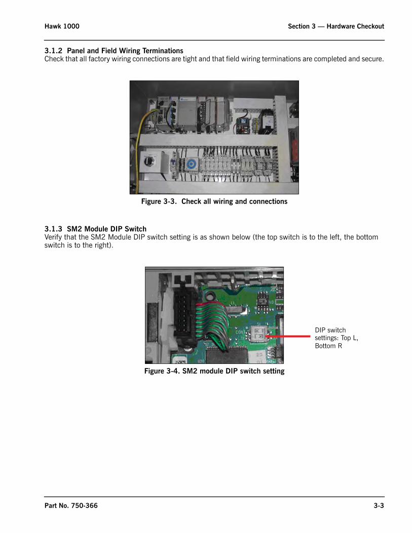
3.1.1 DIN Rail Latch and Expansion I/O Module Locking LeversBefore powering up the control system for the first time, check that all the DIN rail latches and expansion module locking levers are in place (see Figure 3-1 and Figure 3-2).
The module locking levers should all be securely seated to the left.
The base unit and expansion modules do not support removal and insertion under power. While the PLC system is under power, any break in the connection between the power supply and the base unit (i.e. removing the power supply, base unit, or an expansion module) will clear processor memory including the user program. Ensure that the electrical power is OFF before removing or inserting any PLC device.
Figure 3-1. DIN rail latches
Figure 3-2. Expansion I/O Module locking levers
Important!
3-2 Part No. 750-366
Hawk 1000 Section 3 — Hardware Checkout
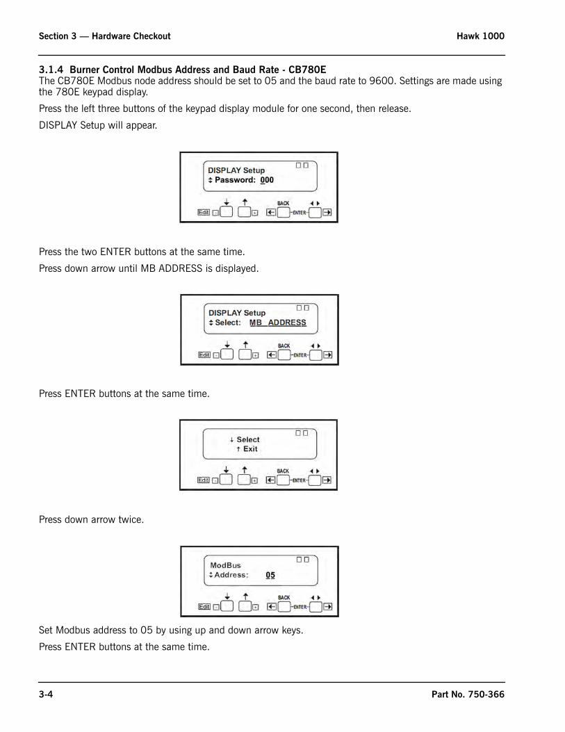
3.1.2 Panel and Field Wiring TerminationsCheck that all factory wiring connections are tight and that field wiring terminations are completed and secure.
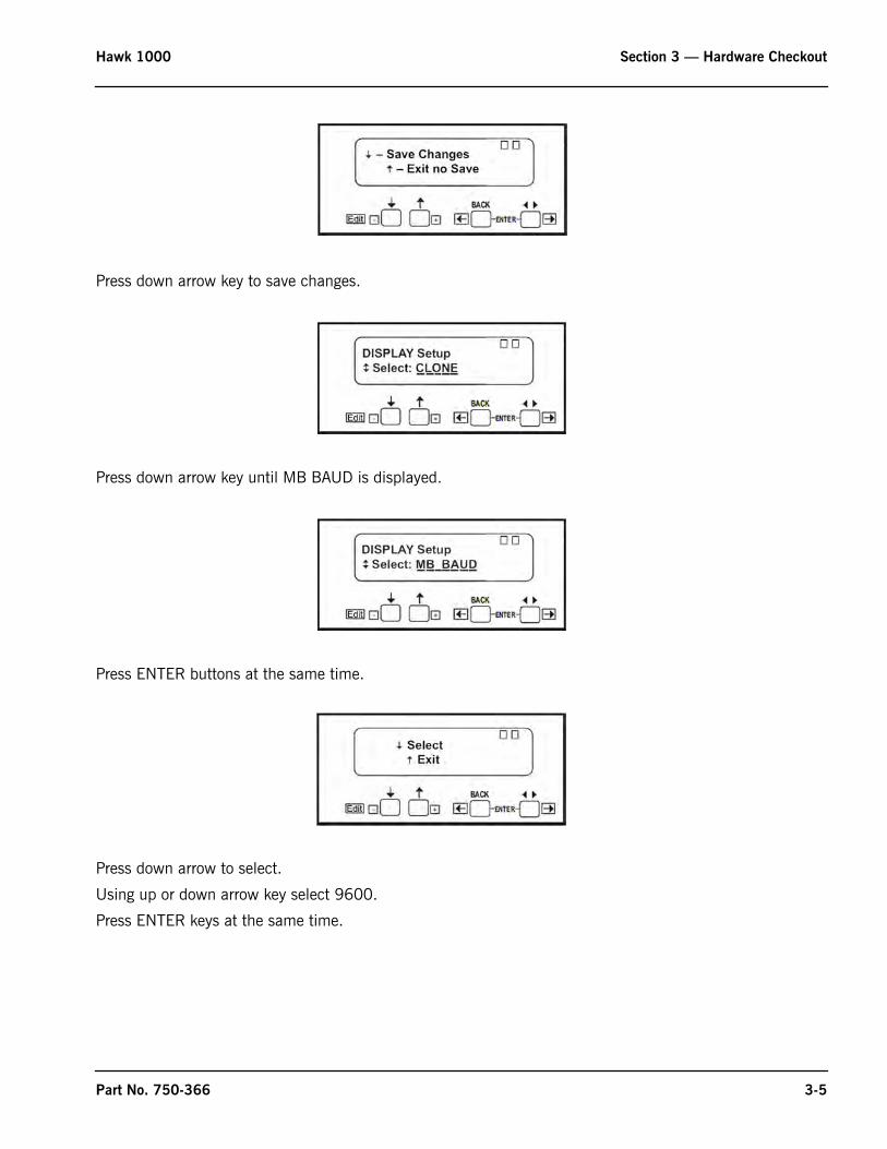
3.1.3 SM2 Module DIP SwitchVerify that the SM2 Module DIP switch setting is as shown below (the top switch is to the left, the bottom switch is to the right).
Figure 3-3. Check all wiring and connections
Figure 3-4. SM2 module DIP switch setting
DIP switchsettings: Top L,Bottom R
Part No. 750-366 3-3
Section 3 — Hardware Checkout Hawk 1000
3.1.4 Burner Control Modbus Address and Baud Rate - CB780EThe CB780E Modbus node address should be set to 05 and the baud rate to 9600. Settings are made using the 780E keypad display.
Press the left three buttons of the keypad display module for one second, then release.
DISPLAY Setup will appear.
Press the two ENTER buttons at the same time.
Press down arrow until MB ADDRESS is displayed.
Press ENTER buttons at the same time.
Press down arrow twice.
Set Modbus address to 05 by using up and down arrow keys.
Press ENTER buttons at the same time.
3-4 Part No. 750-366
Hawk 1000 Section 3 — Hardware Checkout
Press down arrow key to save changes.
Press down arrow key until MB BAUD is displayed.
Press ENTER buttons at the same time.
Press down arrow to select.
Using up or down arrow key select 9600.
Press ENTER keys at the same time.
Part No. 750-366 3-5

Section 3 — Hardware Checkout Hawk 1000
Press down arrow key to save changes.
Press ENTER buttons at the same time.
Press upper arrow key to exit.
3.1.5 Burner Control Modbus Address and Baud Rate - CB120E
The CB120E has built-in Modbus capability; for proper communications the ModBus baud rate and node address need to be correctly set. To check the settings, the CB120E must be powered.
Press the <BACK> or <NEXT> key on the CB120E display until the screen displays PROGRAM SETUP>.
3-6 Part No. 750-366
Hawk 1000 Section 3 — Hardware Checkout
Press the <MODE> then the <NEXT> key until the screen displays BAUD RATE.
Press <MDFY> and use the <BACK> or <NEXT> key to change to 4800. Press <MDFY> to save.
Press the <NEXT> key until UNIT ADDRESS # is displayed. To change the unit address, use the <BACK> or <NEXT> key to change to 5. Press <MDFY> to save.
Press <MODE> to exit the menu.
3.1.6 PLC SwitchVerify that the PLC switch is in the RUN position.
The boiler will not operate if the switch is in the PROG position.
The boiler will immediately stop if the switch is moved to the PROG position.
The switch must be in the PROG position and the Burner switch set to OFF before the PLC program can be copied to a blank SD card in “Logix folder” format.
The switch can be in either PROG or RUN position when copying a PLC program from a SD card containing a Logix folder. No other files should be present on the SD card.
3.2 Modbus Actuator Checks
3.2.1 MountingFasten the actuator using bolts through the mounting bracket, threaded into the face of the actuator. Be sure that the mounting surface rests flat against the mounting bracket and is secure.
The actuator output drive shaft should be connected to the valve shaft with a suitable coupling. The coupling may be connected with set screws and pinned in position or secured with a key.
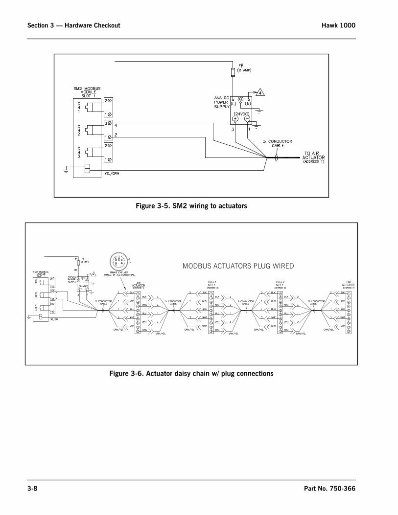
3.2.2 Electrical ConnectionsThe actuators are intended to have one cable connection on the incoming side, (from the previous actuator or the Hawk panel) and one cable connection on the outgoing side, to the next actuator. The cable connectors and mounting plugs are keyed to ensure that the pins all line up correctly. To connect the cable, align the pins and the key and push into place. Turn the threaded collar clockwise to tighten and secure the cable. Secure the cables such that the cables are not pinched and do not interfere with the mechanical movement of the actuated devices.
In some installations, codes or other requirements may call for the actuators to be hard wired. See Figure 3-7.
It is recommended that the actuator drive shaft remain decoupled from the valve shaft (or damper level) until the actuator Modbus address is properly set, the wiring is proven, and the direction of rotation to open the valve/ damper is determined.
Part No. 750-366 3-7
Section 3 — Hardware Checkout Hawk 1000
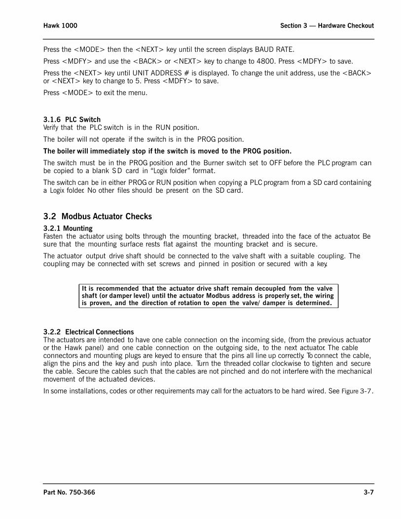
Figure 3-5. SM2 wiring to actuators
Figure 3-6. Actuator daisy chain w/ plug connections
MODBUS ACTUATORS PLUG WIRED
FUEL 1ACT. 1
FUEL 2ACT. 1
3-8 Part No. 750-366
Hawk 1000 Section 3 — Hardware Checkout
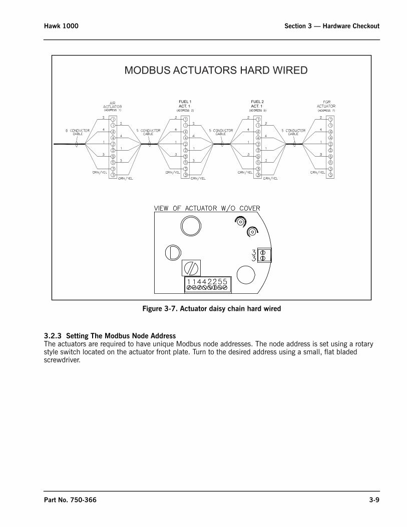
Figure 3-7. Actuator daisy chain hard wired
3.2.3 Setting The Modbus Node AddressThe actuators are required to have unique Modbus node addresses. The node address is set using a rotary style switch located on the actuator front plate. Turn to the desired address using a small, flat bladed screwdriver.
MODBUS ACTUATORS HARD WIRED
FUEL 1ACT. 1
FUEL 2ACT. 1
Part No. 750-366 3-9
Section 3 — Hardware Checkout Hawk 1000
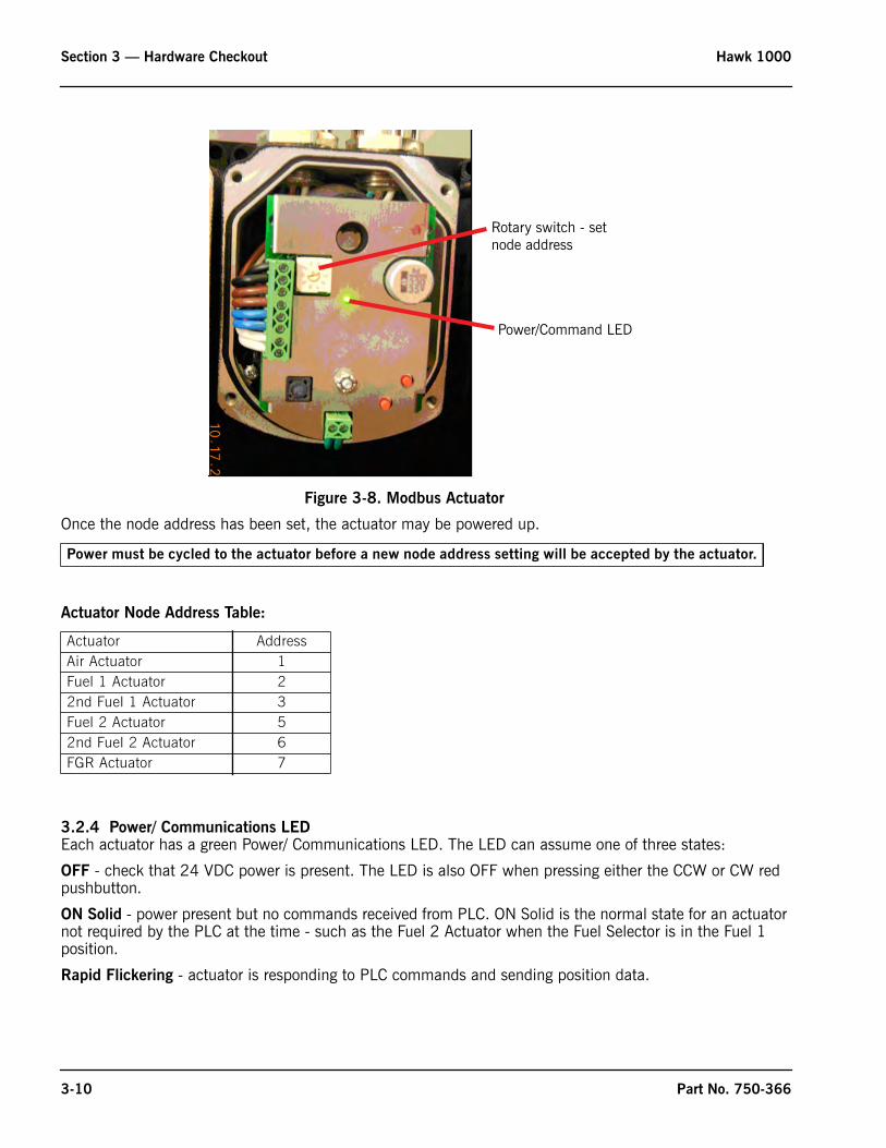
Once the node address has been set, the actuator may be powered up.
Actuator Node Address Table:
3.2.4 Power/ Communications LEDEach actuator has a green Power/ Communications LED. The LED can assume one of three states:
OFF - check that 24 VDC power is present. The LED is also OFF when pressing either the CCW or CW red pushbutton.
ON Solid - power present but no commands received from PLC. ON Solid is the normal state for an actuator not required by the PLC at the time - such as the Fuel 2 Actuator when the Fuel Selector is in the Fuel 1 position.
Rapid Flickering - actuator is responding to PLC commands and sending position data.
Figure 3-8. Modbus Actuator
Power must be cycled to the actuator before a new node address setting will be accepted by the actuator.
Actuator AddressAir Actuator 1Fuel 1 Actuator 22nd Fuel 1 Actuator 3Fuel 2 Actuator 52nd Fuel 2 Actuator 6FGR Actuator 7
Rotary switch - set
Power/Command LED
node address
3-10 Part No. 750-366
Hawk 1000 Section 3 — Hardware Checkout
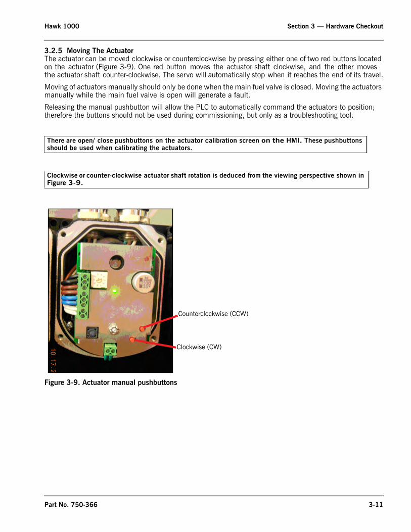
3.2.5 Moving The ActuatorThe actuator can be moved clockwise or counterclockwise by pressing either one of two red buttons located on the actuator (Figure 3-9). One red button moves the actuator shaft clockwise, and the other moves the actuator shaft counter-clockwise. The servo will automatically stop when it reaches the end of its travel.
Moving of actuators manually should only be done when the main fuel valve is closed. Moving the actuators manually while the main fuel valve is open will generate a fault.
Releasing the manual pushbutton will allow the PLC to automatically command the actuators to position; therefore the buttons should not be used during commissioning, but only as a troubleshooting tool.
Figure 3-9. Actuator manual pushbuttons
There are open/ close pushbuttons on the actuator calibration screen on the HMI. These pushbuttons should be used when calibrating the actuators.
Clockwise or counter-clockwise actuator shaft rotation is deduced from the viewing perspective shown in Figure 3-9.
Counterclockwise (CCW)
Clockwise (CW)
Part No. 750-366 3-11

Section 3 — Hardware Checkout Hawk 1000
3-12 Part No. 750-366
www.cleaverbrooks.com
Section 4System Configuration
Introduction . . . . . . . . . . . . . . . . . . . . . . . . . . . . . . . . . . . . . . . . . . . . .4-2Main Menu . . . . . . . . . . . . . . . . . . . . . . . . . . . . . . . . . . . . . . . . . . . . . .4-2Boiler Overview . . . . . . . . . . . . . . . . . . . . . . . . . . . . . . . . . . . . . . . . . . .4-3System Configuration . . . . . . . . . . . . . . . . . . . . . . . . . . . . . . . . . . . . . . .4-4
Boiler Type and Media . . . . . . . . . . . . . . . . . . . . . . . . . . . . . . .4-6Fuel Configuration . . . . . . . . . . . . . . . . . . . . . . . . . . . . . . . . . .4-11Flame Safeguard . . . . . . . . . . . . . . . . . . . . . . . . . . . . . . . . . . .4-12Analog Inputs . . . . . . . . . . . . . . . . . . . . . . . . . . . . . . . . . . . . .4-13Remote Modulation/Remote Set Point . . . . . . . . . . . . . . . . . . . .4-15Actuator Selection . . . . . . . . . . . . . . . . . . . . . . . . . . . . . . . . . .4-17Variable Frequency Drive . . . . . . . . . . . . . . . . . . . . . . . . . . . . .4-18Options . . . . . . . . . . . . . . . . . . . . . . . . . . . . . . . . . . . . . . . . .4-19Configuration Summary . . . . . . . . . . . . . . . . . . . . . . . . . . . . . .4-23
Section 4 — System Configuration Hawk 1000
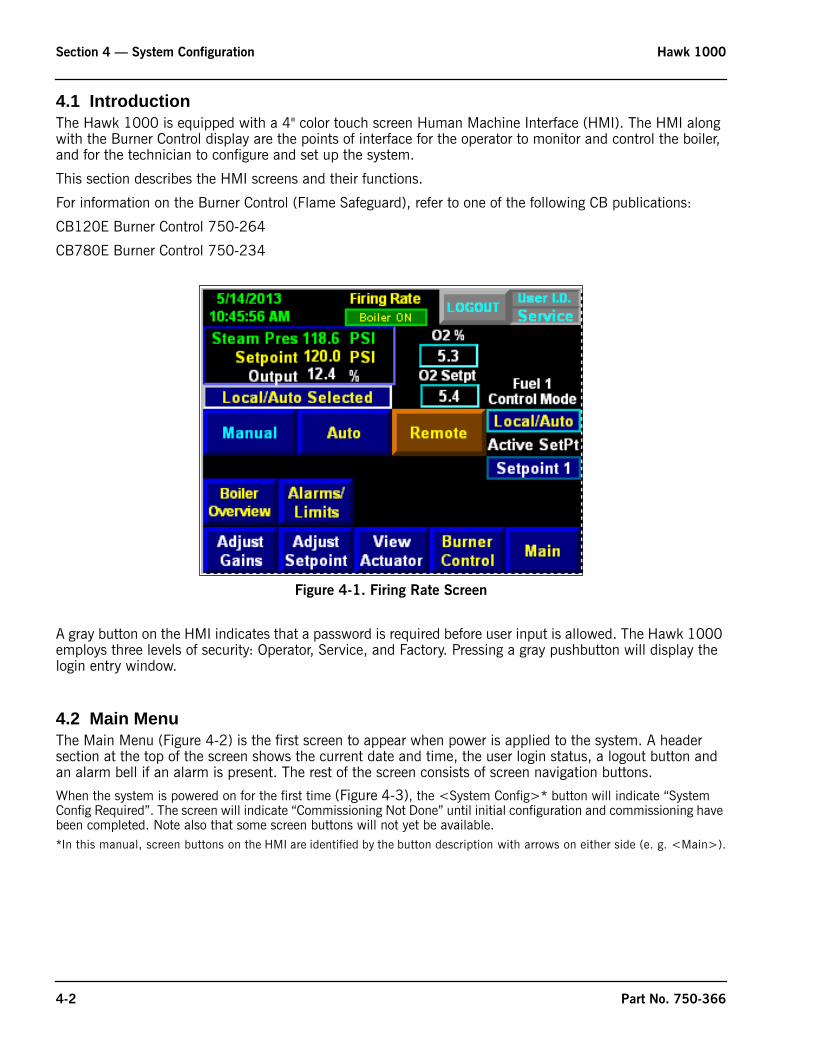
4.1 IntroductionThe Hawk 1000 is equipped with a 4" color touch screen Human Machine Interface (HMI). The HMI along with the Burner Control display are the points of interface for the operator to monitor and control the boiler, and for the technician to configure and set up the system.
This section describes the HMI screens and their functions.
For information on the Burner Control (Flame Safeguard), refer to one of the following CB publications:
CB120E Burner Control 750-264
CB780E Burner Control 750-234
A gray button on the HMI indicates that a password is required before user input is allowed. The Hawk 1000 employs three levels of security: Operator, Service, and Factory. Pressing a gray pushbutton will display the login entry window.
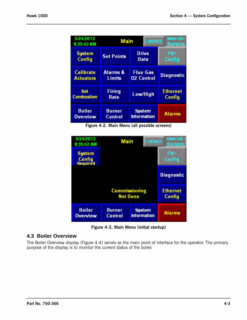
4.2 Main MenuThe Main Menu (Figure 4-2) is the first screen to appear when power is applied to the system. A header section at the top of the screen shows the current date and time, the user login status, a logout button and an alarm bell if an alarm is present. The rest of the screen consists of screen navigation buttons.
When the system is powered on for the first time (Figure 4-3), the <System Config>* button will indicate “System Config Required”. The screen will indicate “Commissioning Not Done” until initial configuration and commissioning have been completed. Note also that some screen buttons will not yet be available.*In this manual, screen buttons on the HMI are identified by the button description with arrows on either side (e. g. <Main>).
Figure 4-1. Firing Rate Screen
4-2 Part No. 750-366
Hawk 1000 Section 4 — System Configuration
Figure 4-3. Main Menu (initial startup)
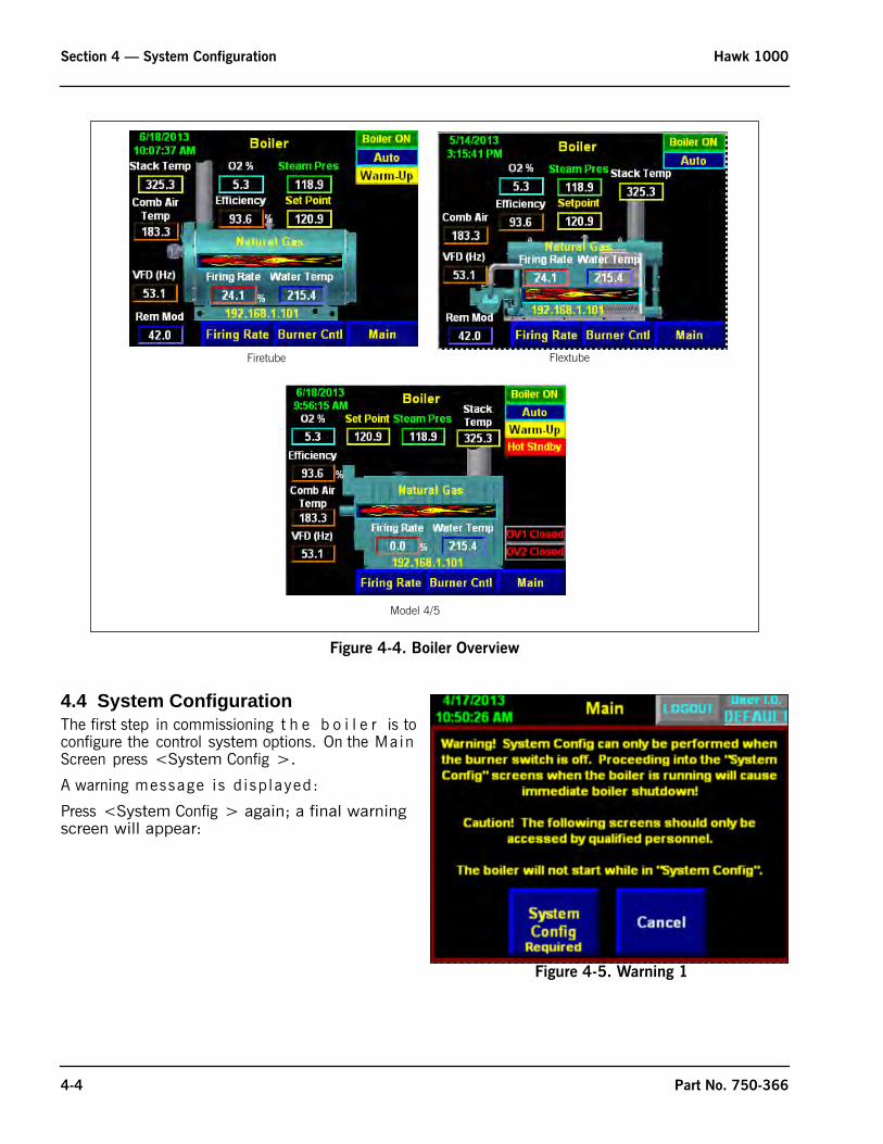
4.3 Boiler OverviewThe Boiler Overview display (Figure 4-4) serves as the main point of interface for the operator. The primary purpose of the display is to monitor the current status of the boiler.
Figure 4-2. Main Menu (all possible screens)
Part No. 750-366 4-3
Section 4 — System Configuration Hawk 1000
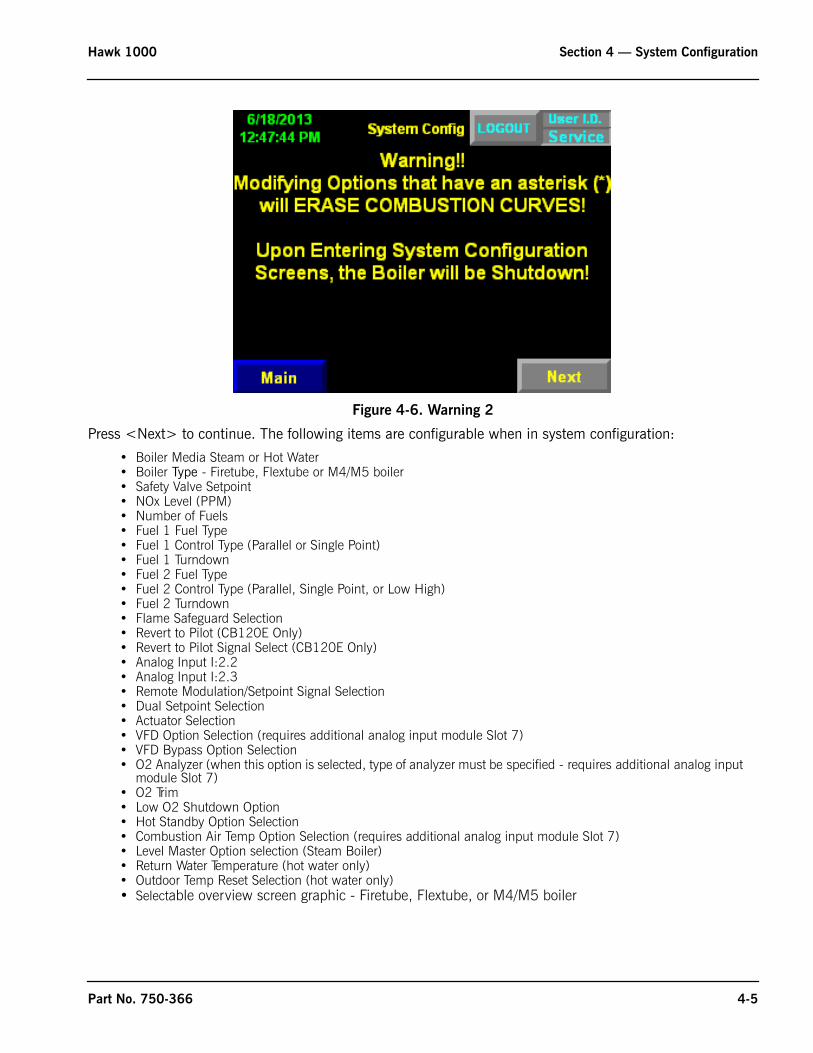
4.4 System ConfigurationThe first step in commissioning t h e b o i l e r is to configure the control system options. On the Main Screen press <System Config >.
A warning message i s d isp layed:
Press <System Config > again; a final warning screen will appear:
Figure 4-4. Boiler Overview
Firetube Flextube
Model 4/5
Figure 4-5. Warning 1
4-4 Part No. 750-366
Hawk 1000 Section 4 — System Configuration
Figure 4-6. Warning 2
Press <Next> to continue. The following items are configurable when in system configuration:
• Boiler Media Steam or Hot Water• Boiler Type - Firetube, Flextube or M4/M5 boiler• Safety Valve Setpoint• NOx Level (PPM)• Number of Fuels• Fuel 1 Fuel Type• Fuel 1 Control Type (Parallel or Single Point)• Fuel 1 Turndown• Fuel 2 Fuel Type• Fuel 2 Control Type (Parallel, Single Point, or Low High)• Fuel 2 Turndown• Flame Safeguard Selection• Revert to Pilot (CB120E Only)• Revert to Pilot Signal Select (CB120E Only)• Analog Input I:2.2• Analog Input I:2.3• Remote Modulation/Setpoint Signal Selection• Dual Setpoint Selection• Actuator Selection• VFD Option Selection (requires additional analog input module Slot 7)• VFD Bypass Option Selection• O2 Analyzer (when this option is selected, type of analyzer must be specified - requires additional analog input
module Slot 7)• O2 Trim• Low O2 Shutdown Option• Hot Standby Option Selection• Combustion Air Temp Option Selection (requires additional analog input module Slot 7)• Level Master Option selection (Steam Boiler)• Return Water Temperature (hot water only)• Outdoor Temp Reset Selection (hot water only)• Selectable overview screen graphic - Firetube, Flextube, or M4/M5 boiler
Part No. 750-366 4-5
Section 4 — System Configuration Hawk 1000
Note that if a configuration setting is marked with an asterisk and the setting is changed the Combustion Curves will be erased.
Note: The boiler will not start while you are in the “System Config” screen.
Note: The firing rate will be put into manual mode upon entering the “System Config” screen.
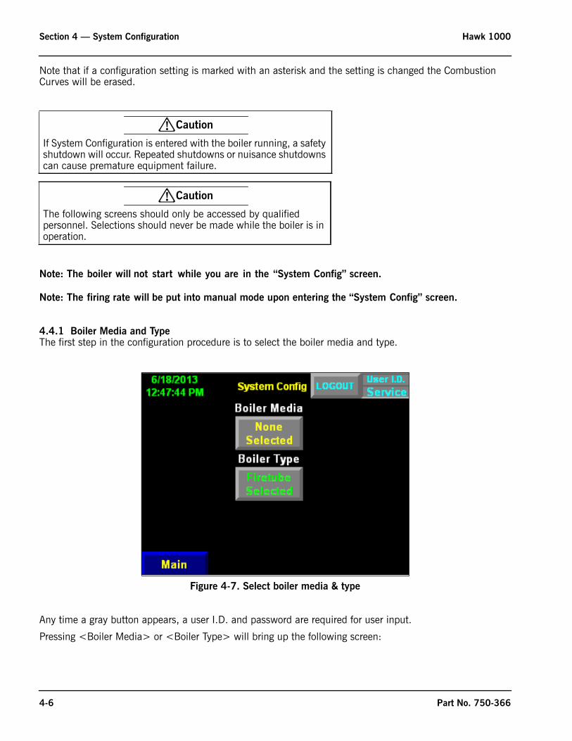
4.4.1 Boiler Media and Type The first step in the configuration procedure is to select the boiler media and type.
Any time a gray button appears, a user I.D. and password are required for user input.
Pressing <Boiler Media> or <Boiler Type> will bring up the following screen:
! Caution
If System Configuration is entered with the boiler running, a safety shutdown will occur. Repeated shutdowns or nuisance shutdowns can cause premature equipment failure.
! Caution
The following screens should only be accessed by qualified personnel. Selections should never be made while the boiler is in operation.
Figure 4-7. Select boiler media & type
4-6 Part No. 750-366
Hawk 1000 Section 4 — System Configuration
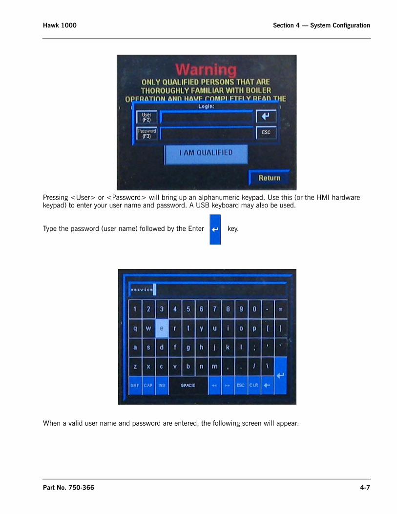
Pressing <User> or <Password> will bring up an alphanumeric keypad. Use this (or the HMI hardware keypad) to enter your user name and password. A USB keyboard may also be used.
Type the password (user name) followed by the Enter key.
When a valid user name and password are entered, the following screen will appear:
Part No. 750-366 4-7
Section 4 — System Configuration Hawk 1000
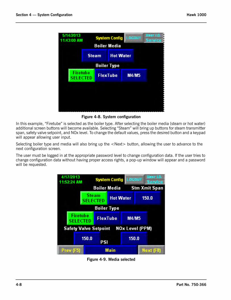
Figure 4-8. System configuration
In this example, “Firetube” is selected as the boiler type. After selecting the boiler media (steam or hot water) additional screen buttons will become available. Selecting “Steam” will bring up buttons for steam transmitter span, safety valve setpoint, and NOx level. To change the default values, press the desired button and a keypad will appear allowing user input.
Selecting boiler type and media will also bring up the <Next> button, allowing the user to advance to the next configuration screen.
The user must be logged in at the appropriate password level to change configuration data. If the user tries to change configuration data without having proper access rights, a pop-up window will appear and a password will be requested.
Figure 4-9. Media selected
4-8 Part No. 750-366
Hawk 1000 Section 4 — System Configuration
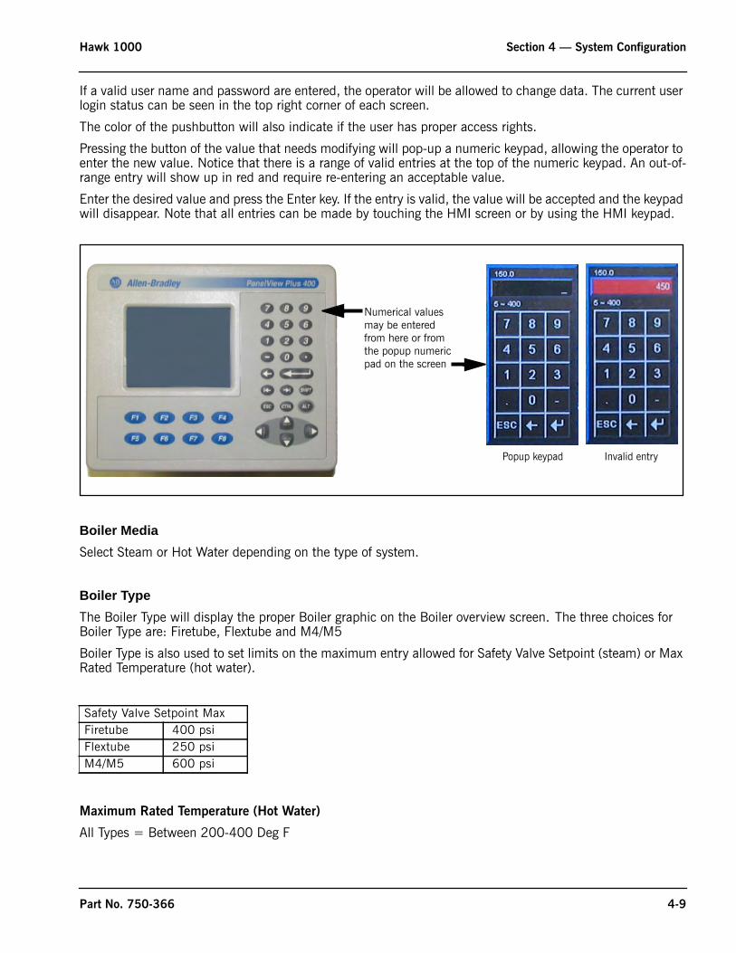
If a valid user name and password are entered, the operator will be allowed to change data. The current user login status can be seen in the top right corner of each screen.
The color of the pushbutton will also indicate if the user has proper access rights.
Pressing the button of the value that needs modifying will pop-up a numeric keypad, allowing the operator to enter the new value. Notice that there is a range of valid entries at the top of the numeric keypad. An out-of-range entry will show up in red and require re-entering an acceptable value.
Enter the desired value and press the Enter key. If the entry is valid, the value will be accepted and the keypad will disappear. Note that all entries can be made by touching the HMI screen or by using the HMI keypad.
Boiler MediaSelect Steam or Hot Water depending on the type of system.
Boiler TypeThe Boiler Type will display the proper Boiler graphic on the Boiler overview screen. The three choices for Boiler Type are: Firetube, Flextube and M4/M5
Boiler Type is also used to set limits on the maximum entry allowed for Safety Valve Setpoint (steam) or Max Rated Temperature (hot water).
Maximum Rated Temperature (Hot Water)
All Types = Between 200-400 Deg F
Safety Valve Setpoint MaxFiretube 400 psiFlextube 250 psiM4/M5 600 psi
Numerical valuesmay be enteredfrom here or fromthe popup numericpad on the screen
Popup keypad Invalid entry
Part No. 750-366 4-9
Section 4 — System Configuration Hawk 1000
Safety Valve Setpoint (steam)
On a steam boiler, the proper safety valve setting should correspond to the pressure setting of the steam safety valve(s) on the boiler.
A hot water boiler is configured similarly. The max rated temperature of the boiler should be entered. This number should not exceed the maximum design temperature of the boiler. Default for hot water boilers is 250º F. Contact your local Cleaver-Brooks representative if you do not know the maximum temperature rating of your boiler.
Steam Transmitter Span The span settings for the steam transmitter is adjustable. The Steam Transmitter Span value cannot be set lower than the Safety Valve Setpoint and cannot be set higher than 1000. Initially the Steam Transmitter Span is populated with a default value:
In hot water systems the supply temperature transmitter is not scalable. The transmitters used must be rated to accommodate the required range:
If the Max Rated Temperature > 250 Deg F the Supply Temp Transmitter is set to 50-300 Deg F.
If the Max Rated Temperature = 250.1 Deg F or greater the Supply Temp Transmitter is set to 50-500 Deg F.
NOx Level (PPM)
Enter the NOx Level for this specific job.
NOx Level can range from 5-150 PPM and is initialized with a value of 60.0 PPM.
Note: On Steam Boilers If NOx Level is less than 60.0 PPM Remote Setpoint and Dual Setpoint Options are Not Available.
When all configurable items on this screen have valid entries, the <Next> button will appear, allowing System Configuration to continue. The next screen is fuel configuration, where number and type of fuels, turndown, and combustion control method are selected.
! Warning
The safety valve setting is critical to the proper operation of the boiler. An incorrect setting could lead to unsafe operation.
Safety Valve Setpoint Steam Transmitter Span15.0 psi or less 15.015.1 to 150.0 150.0150.1 to 300.0 300.0300.1 to 500.0 500.0500.1 to 600.0 600.0
4-10 Part No. 750-366
Hawk 1000 Section 4 — System Configuration
4.4.2 Fuel Configuration
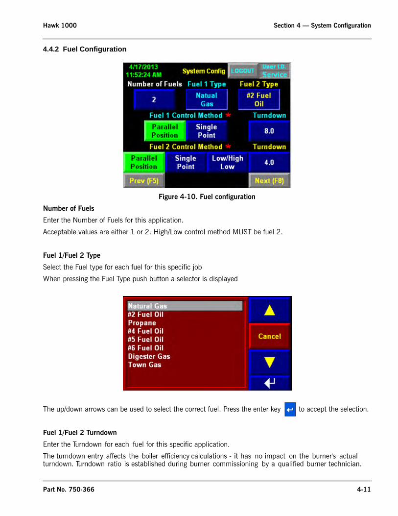
Figure 4-10. Fuel configuration
Number of Fuels
Enter the Number of Fuels for this application.
Acceptable values are either 1 or 2. High/Low control method MUST be fuel 2.
Fuel 1/Fuel 2 Type
Select the Fuel type for each fuel for this specific job
When pressing the Fuel Type push button a selector is displayed
The up/down arrows can be used to select the correct fuel. Press the enter key to accept the selection.
Fuel 1/Fuel 2 Turndown
Enter the Turndown for each fuel for this specific application.
The turndown entry affects the boiler efficiency calculations - it has no impact on the burner's actual turndown. Turndown ratio is established during burner commissioning by a qualified burner technician.
Part No. 750-366 4-11
Section 4 — System Configuration Hawk 1000
Fuel 1/Fuel 2 Control Method
Select the type of control method for each fuel for this specific job.
Acceptable values for fuel 1 are Parallel Positioning or Single Point positioning.
Acceptable values for fuel 2 are Parallel Positioning, Single Point positioning or Low/High.
Note - Single Point positioning cannot be selected in conjunction with parallel positioning.
When fuel configuration is complete, press <Next> to go to Flame Safeguard configuration.
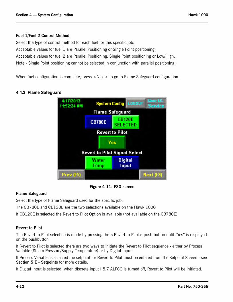
4.4.3 Flame Safeguard
Figure 4-11. FSG screen
Flame Safeguard
Select the type of Flame Safeguard used for the specific job.
The CB780E and CB120E are the two selections available on the Hawk 1000
If CB120E is selected the Revert to Pilot Option is available (not available on the CB780E).
Revert to Pilot
The Revert to Pilot selection is made by pressing the <Revert to Pilot> push button until “Yes” is displayed on the pushbutton.
If Revert to Pilot is selected there are two ways to initiate the Revert to Pilot sequence - either by Process Variable (Steam Pressure/Supply Temperature) or by Digital Input.
If Process Variable is selected the setpoint for Revert to Pilot must be entered from the Setpoint Screen - see Section 5 E - Setpoints for more details.
If Digital Input is selected, when discrete input I:5.7 ALFCO is turned off, Revert to Pilot will be initiated.
4-12 Part No. 750-366
Hawk 1000 Section 4 — System Configuration
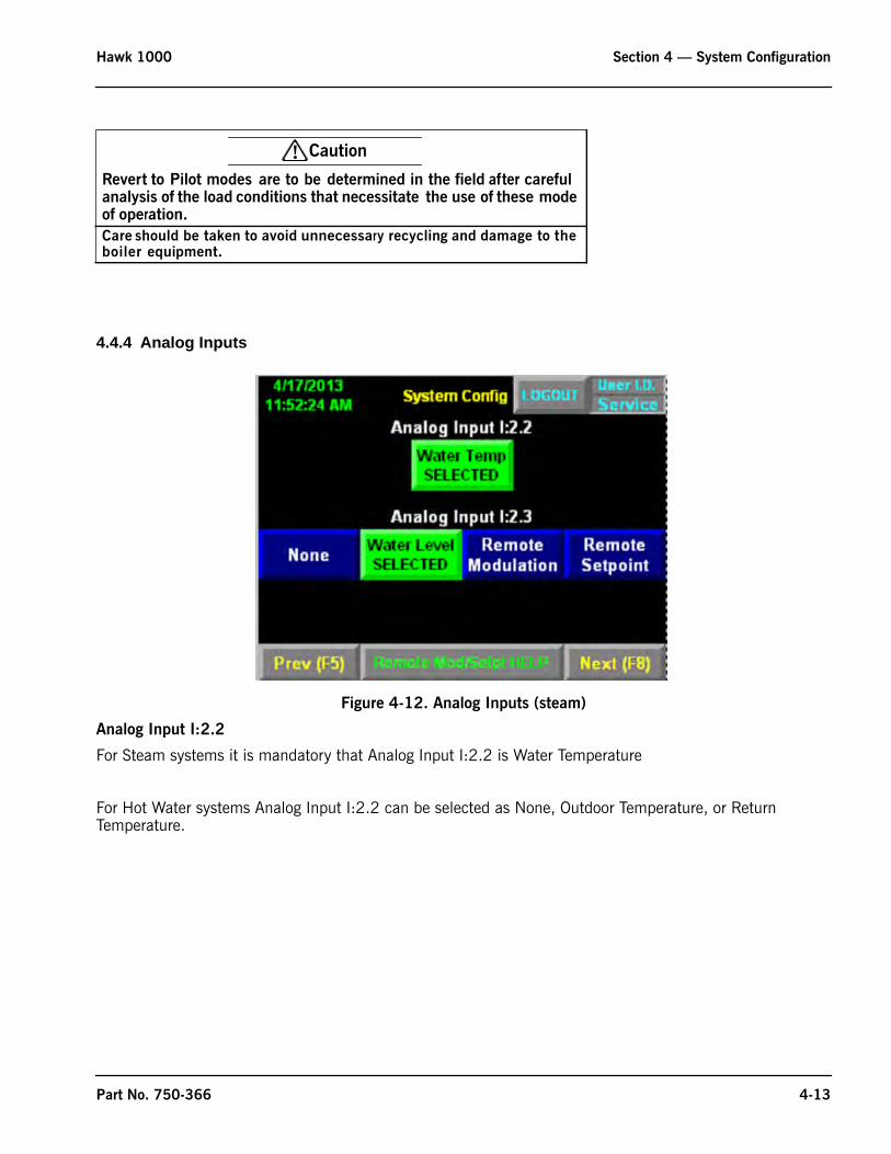
4.4.4 Analog Inputs
Figure 4-12. Analog Inputs (steam)
Analog Input I:2.2
For Steam systems it is mandatory that Analog Input I:2.2 is Water Temperature
For Hot Water systems Analog Input I:2.2 can be selected as None, Outdoor Temperature, or Return Temperature.
! Caution
Revert to Pilot modes are to be determined in the field after careful analysis of the load conditions that necessitate the use of these mode of operation.
Care should be taken to avoid unnecessary recycling and damage to the boiler equipment.
Part No. 750-366 4-13
Section 4 — System Configuration Hawk 1000
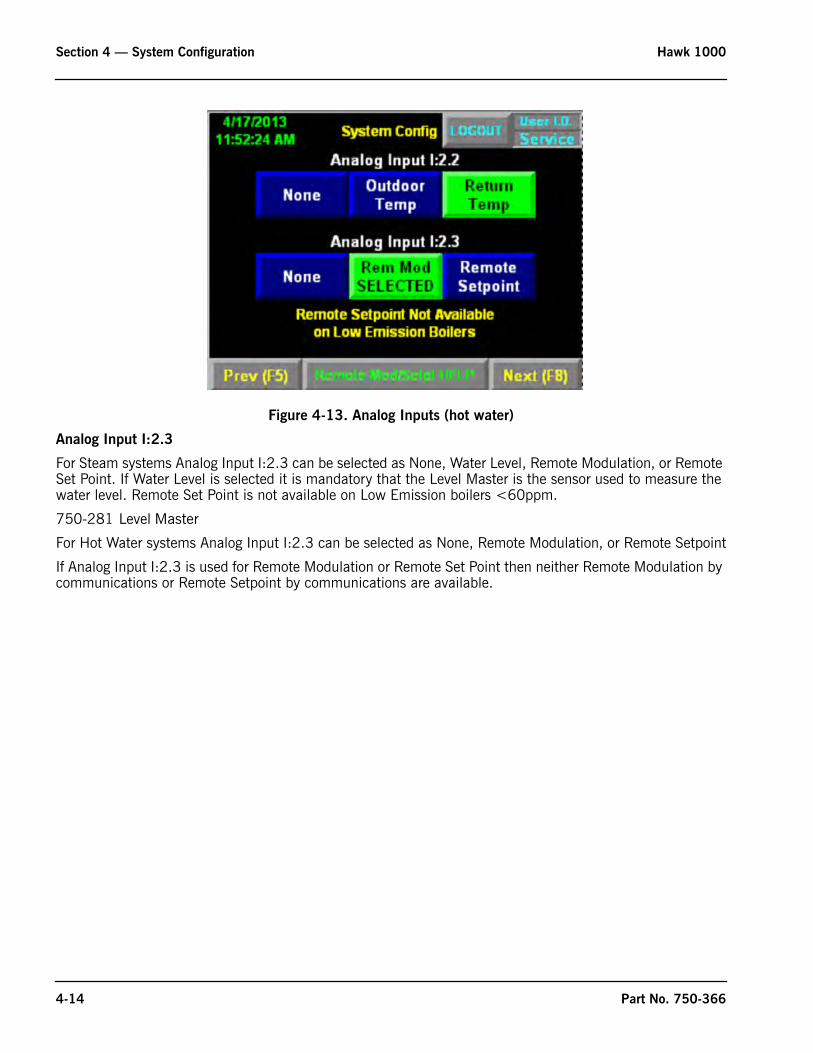
Figure 4-13. Analog Inputs (hot water)
Analog Input I:2.3
For Steam systems Analog Input I:2.3 can be selected as None, Water Level, Remote Modulation, or Remote Set Point. If Water Level is selected it is mandatory that the Level Master is the sensor used to measure the water level. Remote Set Point is not available on Low Emission boilers <60ppm.
750-281 Level Master
For Hot Water systems Analog Input I:2.3 can be selected as None, Remote Modulation, or Remote Setpoint
If Analog Input I:2.3 is used for Remote Modulation or Remote Set Point then neither Remote Modulation by communications or Remote Setpoint by communications are available.
4-14 Part No. 750-366
Hawk 1000 Section 4 — System Configuration
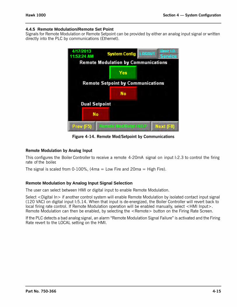
4.4.5 Remote Modulation/Remote Set PointSignals for Remote Modulation or Remote Setpoint can be provided by either an analog input signal or written directly into the PLC by communications (Ethernet).
Figure 4-14. Remote Mod/Setpoint by Communications
Remote Modulation by Analog Input
This configures the Boiler Controller to receive a remote 4-20mA signal on input I:2.3 to control the firing rate of the boiler.
The signal is scaled from 0-100%, (4ma = Low Fire and 20ma = High Fire).
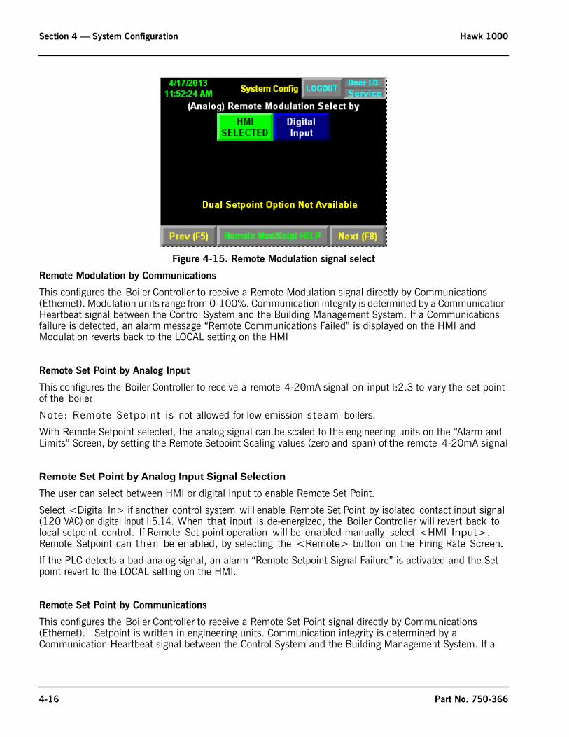
Remote Modulation by Analog Input Signal SelectionThe user can select between HMI or digital input to enable Remote Modulation.
Select <Digital In> if another control system will enable Remote Modulation by isolated contact input signal (120 VAC) on digital input I:5.14. When that input is de-energized, the Boiler Controller will revert back to local firing rate control. If Remote Modulation operation will be enabled manually, select <HMI Input>. Remote Modulation can then be enabled, by selecting the <Remote> button on the Firing Rate Screen.
If the PLC detects a bad analog signal, an alarm “Remote Modulation Signal Failure” is activated and the Firing Rate revert to the LOCAL setting on the HMI.
Part No. 750-366 4-15
Section 4 — System Configuration Hawk 1000
Figure 4-15. Remote Modulation signal select
Remote Modulation by Communications
This configures the Boiler Controller to receive a Remote Modulation signal directly by Communications (Ethernet). Modulation units range from 0-100%. Communication integrity is determined by a Communication Heartbeat signal between the Control System and the Building Management System. If a Communications failure is detected, an alarm message “Remote Communications Failed” is displayed on the HMI and Modulation reverts back to the LOCAL setting on the HMI
Remote Set Point by Analog Input
This configures the Boiler Controller to receive a remote 4-20mA signal on input I:2.3 to vary the set point of the boiler.
Note: Remote Setpoint is not allowed for low emission s team boilers.
With Remote Setpoint selected, the analog signal can be scaled to the engineering units on the “Alarm and Limits” Screen, by setting the Remote Setpoint Scaling values (zero and span) of the remote 4-20mA signal
Remote Set Point by Analog Input Signal SelectionThe user can select between HMI or digital input to enable Remote Set Point.
Select <Digital In> if another control system will enable Remote Set Point by isolated contact input signal (120 VAC) on digital input I:5.14. When that input is de-energized, the Boiler Controller will revert back to local setpoint control. If Remote Set point operation will be enabled manually, select <HMI Input>. Remote Setpoint can then be enabled, by selecting the <Remote> button on the Firing Rate Screen.
If the PLC detects a bad analog signal, an alarm “Remote Setpoint Signal Failure” is activated and the Set point revert to the LOCAL setting on the HMI.
Remote Set Point by Communications
This configures the Boiler Controller to receive a Remote Set Point signal directly by Communications (Ethernet). Setpoint is written in engineering units. Communication integrity is determined by a Communication Heartbeat signal between the Control System and the Building Management System. If a
4-16 Part No. 750-366
Hawk 1000 Section 4 — System Configuration
Communications failure is detected, an alarm message “Remote Communications Failed” is displayed on the HMI and Setpoint reverts back to the LOCAL setting on the HMI
Dual Set PointDual Set Point control - traditionally referred to as night setback - allows the Boiler Controller to easily switch from the primary set point (Set Point 1) to the setback set point (Set Point 2). Set Point 1 is the primary set point for the Controller and is the only set point available if the Dual Set Point option is disallowed (see below). Setback can be initiated manually (through the HMI on the Firing Rate screen) or remotely (by energizing an isolated contact input signal (120 VAC) on digital input I:5.14. Press the button to the right of “Dual Set Point Selection By” to toggle between <HMI Input> and <Digital In>.
The Dual Set Point option is not allowed when Remote Modulation, or Remote Set Point options are enabled.
Selecting <Yes> to Dual Setpoint enables dual Set Point control. This option is not allowed for low emission steam boilers (<60 ppm).
4.4.6 Actuator Selection
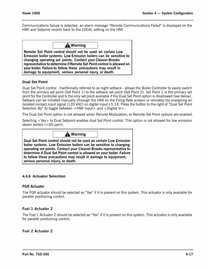
FGR Actuator
The FGR actuator should be selected as “Yes” if it is present on this system. This actuator is only available for parallel positioning control.
Fuel 1 Actuator 2
The Fuel 1 Actuator 2 should be selected as “Yes” if it is present on this system. This actuator is only available for parallel positioning control.
Fuel 2 Actuator 2
! Warning
Remote Set Point control should not be used on certain Low Emission boiler systems. Low Emission boilers can be sensitive to changing operating set points. Contact your Cleaver-Brooks representative to determine if Remote Set Point control is allowed on your boiler. Failure to follow these precautions may result in damage to equipment, serious personal injury, or death.
! Warning
Dual Set Point control should not be used on certain Low Emission boiler systems. Low Emission boilers can be sensitive to changing operating set points. Contact your Cleaver-Brooks representative to determine if Dual Set Point control is allowed on your boiler. Failure to follow these precautions may result in damage to equipment, serious personal injury, or death.
Part No. 750-366 4-17
Section 4 — System Configuration Hawk 1000
The Fuel 2 Actuator 2 should be selected as “Yes” if it is present on this system. This actuator is only available for parallel positioning control.
Figure 4-16. Actuator selection
4.4.7 Variable Frequency Drive
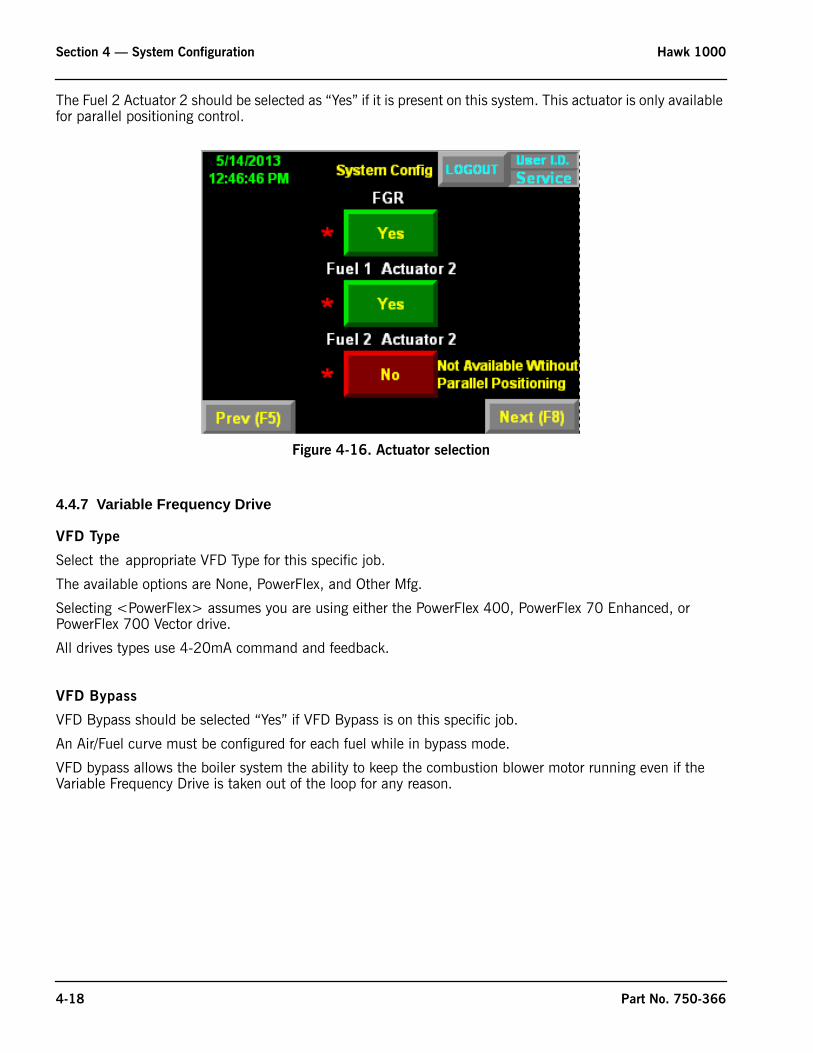
VFD Type
Select the appropriate VFD Type for this specific job.
The available options are None, PowerFlex, and Other Mfg.
Selecting <PowerFlex> assumes you are using either the PowerFlex 400, PowerFlex 70 Enhanced, or PowerFlex 700 Vector drive.
All drives types use 4-20mA command and feedback.
VFD Bypass
VFD Bypass should be selected “Yes” if VFD Bypass is on this specific job.
An Air/Fuel curve must be configured for each fuel while in bypass mode.
VFD bypass allows the boiler system the ability to keep the combustion blower motor running even if the Variable Frequency Drive is taken out of the loop for any reason.
4-18 Part No. 750-366
Hawk 1000 Section 4 — System Configuration
Figure 4-17. VFD screen
Variable Frequency Drive for Combustion Air Fan Motor
Variable frequency drives (VFDs) offer many benefits to reduce energy costs and extend the life of mechanical equipment.
The optional Variable Frequency Drive (VFD; see Figure 2-7) controls the speed of the combustion air fan motor for the purposes of improving boiler efficiency and reducing electrical energy consumption.
4.4.8 Options
Oxygen Analyzer
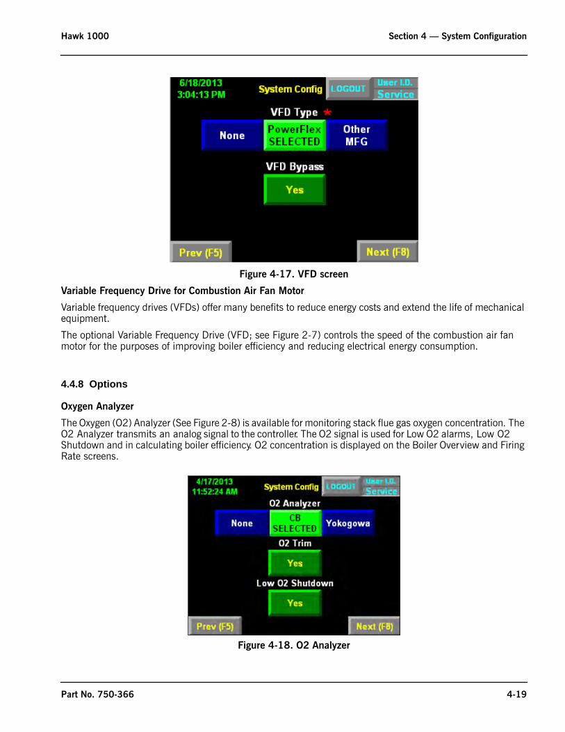
The Oxygen (O2) Analyzer (See Figure 2-8) is available for monitoring stack flue gas oxygen concentration. The O2 Analyzer transmits an analog signal to the controller. The O2 signal is used for Low O2 alarms, Low O2 Shutdown and in calculating boiler efficiency. O2 concentration is displayed on the Boiler Overview and Firing Rate screens.
Figure 4-18. O2 Analyzer
Part No. 750-366 4-19
Section 4 — System Configuration Hawk 1000
O2 Trim
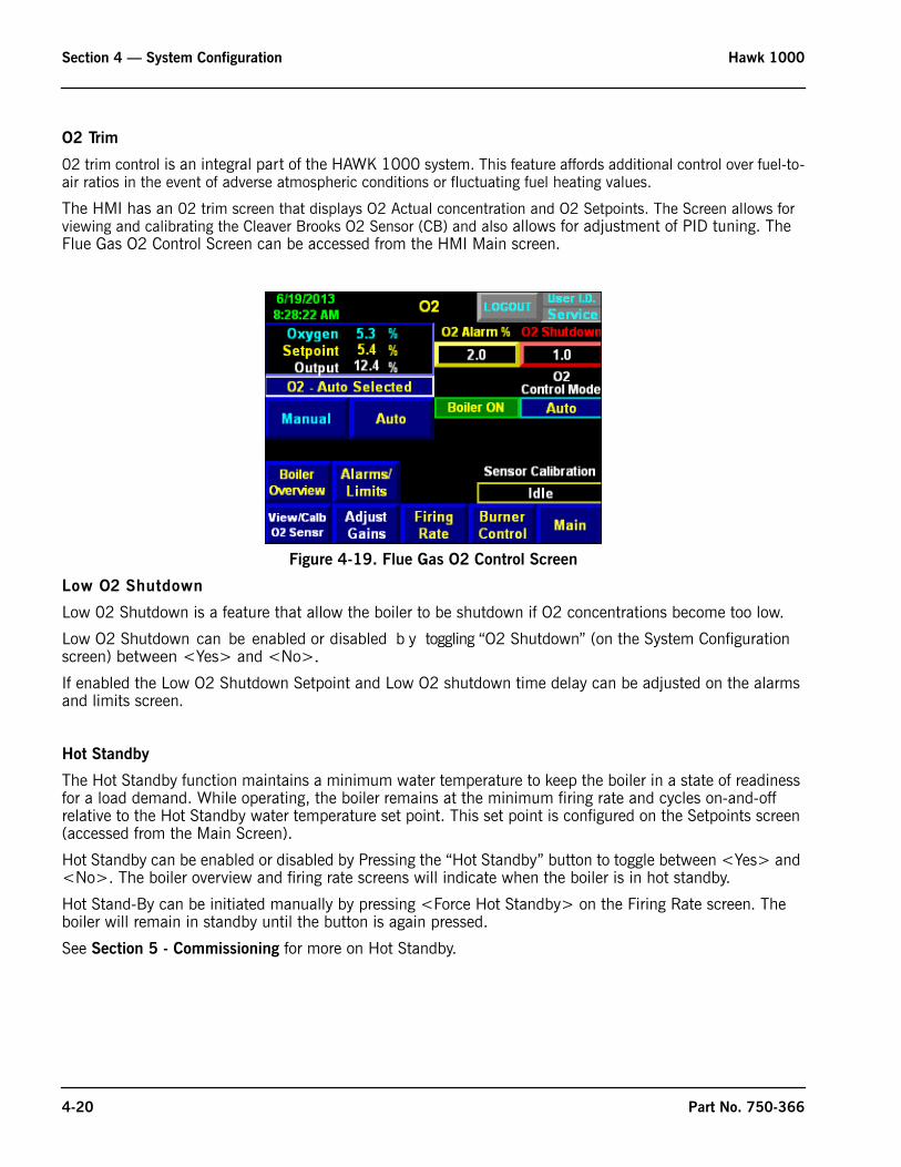
02 trim control is an integral part of the HAWK 1000 system. This feature affords additional control over fuel-to-air ratios in the event of adverse atmospheric conditions or fluctuating fuel heating values.
The HMI has an 02 trim screen that displays O2 Actual concentration and O2 Setpoints. The Screen allows for viewing and calibrating the Cleaver Brooks O2 Sensor (CB) and also allows for adjustment of PID tuning. The Flue Gas O2 Control Screen can be accessed from the HMI Main screen.
Low O2 Shutdown
Low 02 Shutdown is a feature that allow the boiler to be shutdown if O2 concentrations become too low.
Low O2 Shutdown can be enabled or disabled b y toggling “O2 Shutdown” (on the System Configuration screen) between <Yes> and <No>.If enabled the Low O2 Shutdown Setpoint and Low O2 shutdown time delay can be adjusted on the alarms and limits screen.
Hot Standby
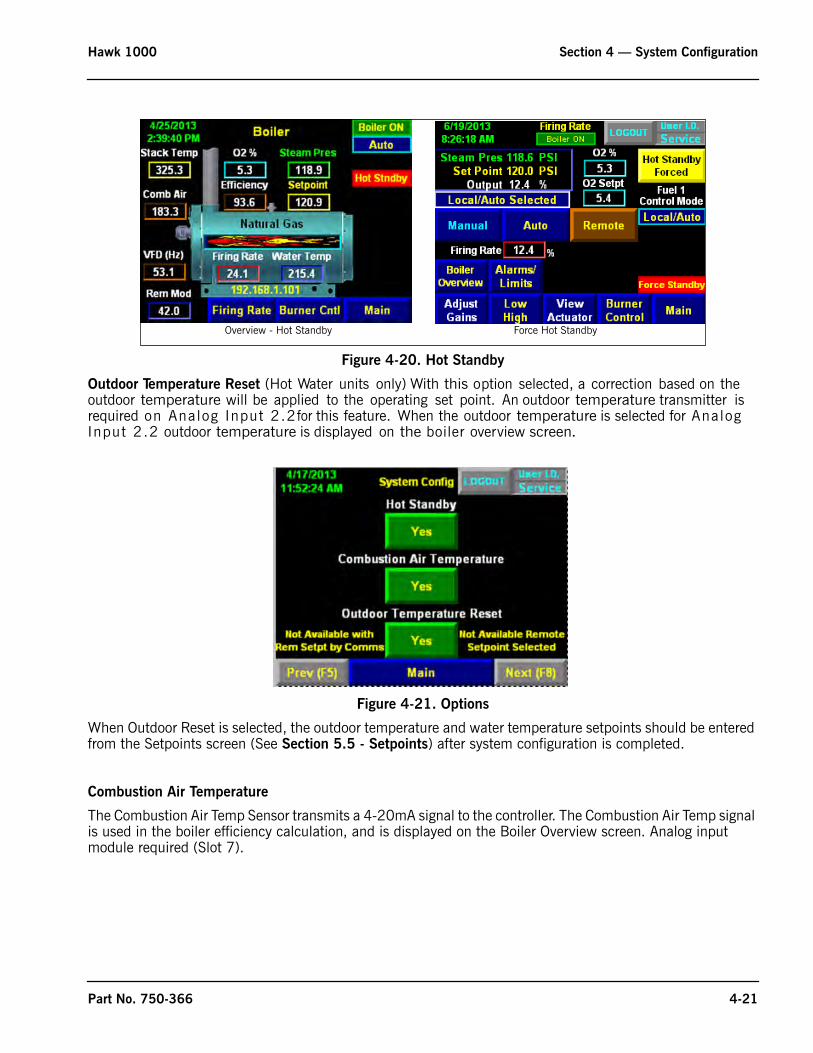
The Hot Standby function maintains a minimum water temperature to keep the boiler in a state of readiness for a load demand. While operating, the boiler remains at the minimum firing rate and cycles on-and-off relative to the Hot Standby water temperature set point. This set point is configured on the Setpoints screen (accessed from the Main Screen).
Hot Standby can be enabled or disabled by Pressing the “Hot Standby” button to toggle between <Yes> and <No>. The boiler overview and firing rate screens will indicate when the boiler is in hot standby.
Hot Stand-By can be initiated manually by pressing <Force Hot Standby> on the Firing Rate screen. The boiler will remain in standby until the button is again pressed.
See Section 5 - Commissioning for more on Hot Standby.
Figure 4-19. Flue Gas O2 Control Screen
4-20 Part No. 750-366
Hawk 1000 Section 4 — System Configuration
Outdoor Temperature Reset (Hot Water units only) With this option selected, a correction based on the outdoor temperature will be applied to the operating set point. An outdoor temperature transmitter is required on Analog Input 2.2for this feature. When the outdoor temperature is selected for Analog Input 2.2 outdoor temperature is displayed on the boiler overview screen.
Figure 4-21. Options
When Outdoor Reset is selected, the outdoor temperature and water temperature setpoints should be entered from the Setpoints screen (See Section 5.5 - Setpoints) after system configuration is completed.
Combustion Air Temperature
The Combustion Air Temp Sensor transmits a 4-20mA signal to the controller. The Combustion Air Temp signal is used in the boiler efficiency calculation, and is displayed on the Boiler Overview screen. Analog input module required (Slot 7).
Figure 4-20. Hot Standby
Overview - Hot Standby Force Hot Standby
Part No. 750-366 4-21
Section 4 — System Configuration Hawk 1000
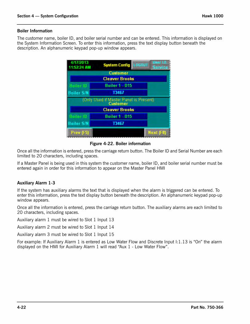
Boiler Information
The customer name, boiler ID, and boiler serial number and can be entered. This information is displayed on the System Information Screen. To enter this information, press the text display button beneath the description. An alphanumeric keypad pop-up window appears.
Figure 4-22. Boiler information
Once all the information is entered, press the carriage return button. The Boiler ID and Serial Number are each limited to 20 characters, including spaces.
If a Master Panel is being used in this system the customer name, boiler ID, and boiler serial number must be entered again in order for this information to appear on the Master Panel HMI
Auxiliary Alarm 1-3
If the system has auxiliary alarms the text that is displayed when the alarm is triggered can be entered. To enter this information, press the text display button beneath the description. An alphanumeric keypad pop-up window appears.
Once all the information is entered, press the carriage return button. The auxiliary alarms are each limited to 20 characters, including spaces.
Auxiliary alarm 1 must be wired to Slot 1 Input 13
Auxiliary alarm 2 must be wired to Slot 1 Input 14
Auxiliary alarm 3 must be wired to Slot 1 Input 15
For example: If Auxiliary Alarm 1 is entered as Low Water Flow and Discrete Input I:1.13 is “On” the alarm displayed on the HMI for Auxiliary Alarm 1 will read “Aux 1 - Low Water Flow”.
4-22 Part No. 750-366
Hawk 1000 Section 4 — System Configuration
Figure 4-23. Aux inputs
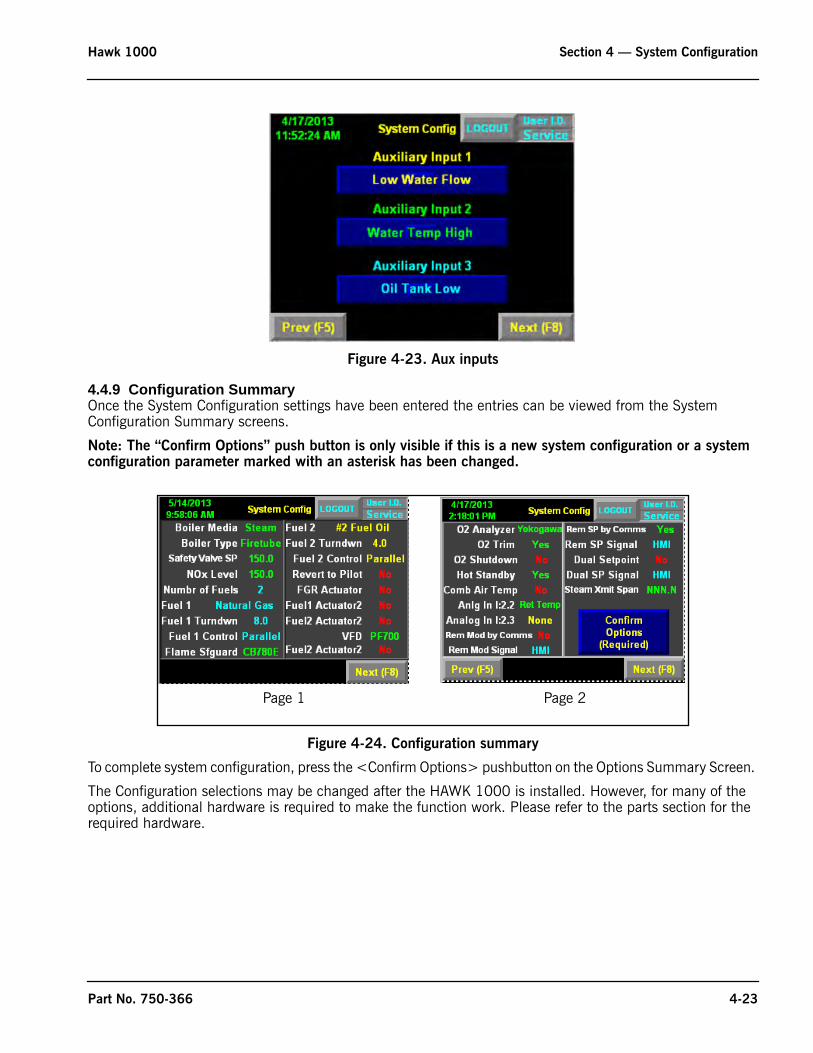
4.4.9 Configuration SummaryOnce the System Configuration settings have been entered the entries can be viewed from the System Configuration Summary screens.
Note: The “Confirm Options” push button is only visible if this is a new system configuration or a system configuration parameter marked with an asterisk has been changed.
Figure 4-24. Configuration summary
To complete system configuration, press the <Confirm Options> pushbutton on the Options Summary Screen.
The Configuration selections may be changed after the HAWK 1000 is installed. However, for many of the options, additional hardware is required to make the function work. Please refer to the parts section for the required hardware.
Page 1 Page 2
Part No. 750-366 4-23

Section 4 — System Configuration Hawk 1000
4-24 Part No. 750-366
www.cleaverbrooks.com
Section 5Commissioning
Commissioning the Actuators . . . . . . . . . . . . . . . . . . . . . . . . . . . . . . . . . . . . . . . . . . . . . . . . 5-2Setting Combustion - Parallel Positioning . . . . . . . . . . . . . . . . . . . . . . . . . . . . . . . . . . . . . . . . 5-4
Store Purge . . . . . . . . . . . . . . . . . . . . . . . . . . . . . . . . . . . . . . . . . . . . . . . . . . . . 5-5Store Lightoff . . . . . . . . . . . . . . . . . . . . . . . . . . . . . . . . . . . . . . . . . . . . . . . . . . . 5-6Curve Setup . . . . . . . . . . . . . . . . . . . . . . . . . . . . . . . . . . . . . . . . . . . . . . . . . . . 5-7
Setting Combustion - Single Point Positioning . . . . . . . . . . . . . . . . . . . . . . . . . . . . . . . . . . . . . 5-8VFD or O2 Trim . . . . . . . . . . . . . . . . . . . . . . . . . . . . . . . . . . . . . . . . . . . . . . . . . 5-8No VFD or O2 Trim . . . . . . . . . . . . . . . . . . . . . . . . . . . . . . . . . . . . . . . . . . . . . . 5-8
Setting Combustion - Low/High/Low . . . . . . . . . . . . . . . . . . . . . . . . . . . . . . . . . . . . . . . . . . . 5-8Firing Rate Screen . . . . . . . . . . . . . . . . . . . . . . . . . . . . . . . . . . . . . . . . . . . . . . . . . . . . . . . . 5-9Alarms and Limits . . . . . . . . . . . . . . . . . . . . . . . . . . . . . . . . . . . . . . . . . . . . . . . . . . . . . . . . 5-11
Low O2 . . . . . . . . . . . . . . . . . . . . . . . . . . . . . . . . . . . . . . . . . . . . . . . . . . . . . . 5-11Low Steam Pressure . . . . . . . . . . . . . . . . . . . . . . . . . . . . . . . . . . . . . . . . . . . . . . 5-11Mod. Rate Limiter, Max. O2 Correct, Remote Shutdown by Comms. . . . . . . . . . . . . 5-12Stack Low Temp. Hold . . . . . . . . . . . . . . . . . . . . . . . . . . . . . . . . . . . . . . . . . . . . 5-12
Setpoints . . . . . . . . . . . . . . . . . . . . . . . . . . . . . . . . . . . . . . . . . . . . . . . . . . . . . . . . . . . . . . . 5-13Operating Setpoint . . . . . . . . . . . . . . . . . . . . . . . . . . . . . . . . . . . . . . . . . . . . . . . 5-13Outdoor Temperature Reset (Hot Water only) . . . . . . . . . . . . . . . . . . . . . . . . . . . . . 5-13Revert to Pilot (CB 120E only) . . . . . . . . . . . . . . . . . . . . . . . . . . . . . . . . . . . . . . 5-14
O2 Trim . . . . . . . . . . . . . . . . . . . . . . . . . . . . . . . . . . . . . . . . . . . . . . . . . . . . . . . . . . . . . . . 5-15Drive Data . . . . . . . . . . . . . . . . . . . . . . . . . . . . . . . . . . . . . . . . . . . . . . . . . . . . . . . . . . . . . 5-16Ethernet Configuration. . . . . . . . . . . . . . . . . . . . . . . . . . . . . . . . . . . . . . . . . . . . . . . . . . . . . . 5-16Two Boiler Lead Lag . . . . . . . . . . . . . . . . . . . . . . . . . . . . . . . . . . . . . . . . . . . . . . . . . . . . . . . 5-17Thermal Shock Routine . . . . . . . . . . . . . . . . . . . . . . . . . . . . . . . . . . . . . . . . . . . . . . . . . . . . . 5-18
Section 5 — Commissioning Hawk 1000
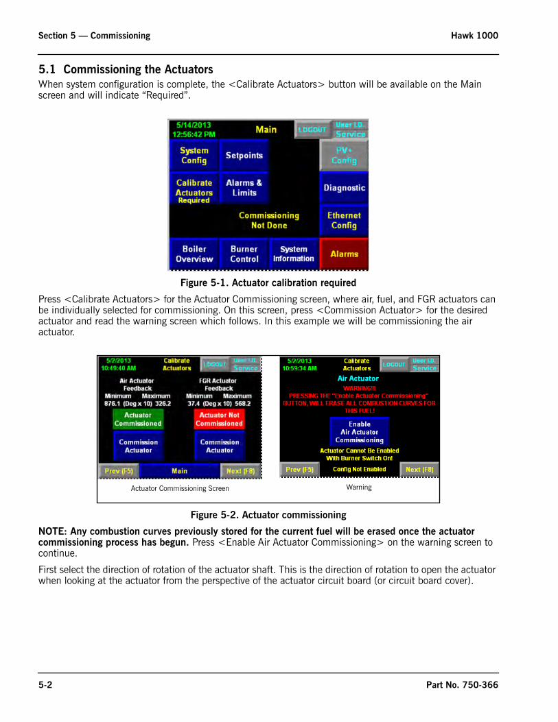
5.1 Commissioning the Actuators
When system configuration is complete, the <Calibrate Actuators> button will be available on the Main screen and will indicate “Required”.
Figure 5-1. Actuator calibration required
Press <Calibrate Actuators> for the Actuator Commissioning screen, where air, fuel, and FGR actuators can be individually selected for commissioning. On this screen, press <Commission Actuator> for the desired actuator and read the warning screen which follows. In this example we will be commissioning the air actuator.
Figure 5-2. Actuator commissioning
NOTE: Any combustion curves previously stored for the current fuel will be erased once the actuator commissioning process has begun. Press <Enable Air Actuator Commissioning> on the warning screen to continue.
First select the direction of rotation of the actuator shaft. This is the direction of rotation to open the actuator when looking at the actuator from the perspective of the actuator circuit board (or circuit board cover).
Actuator Commissioning Screen Warning
5-2 Part No. 750-366
Hawk 1000 Section 5 — Commissioning
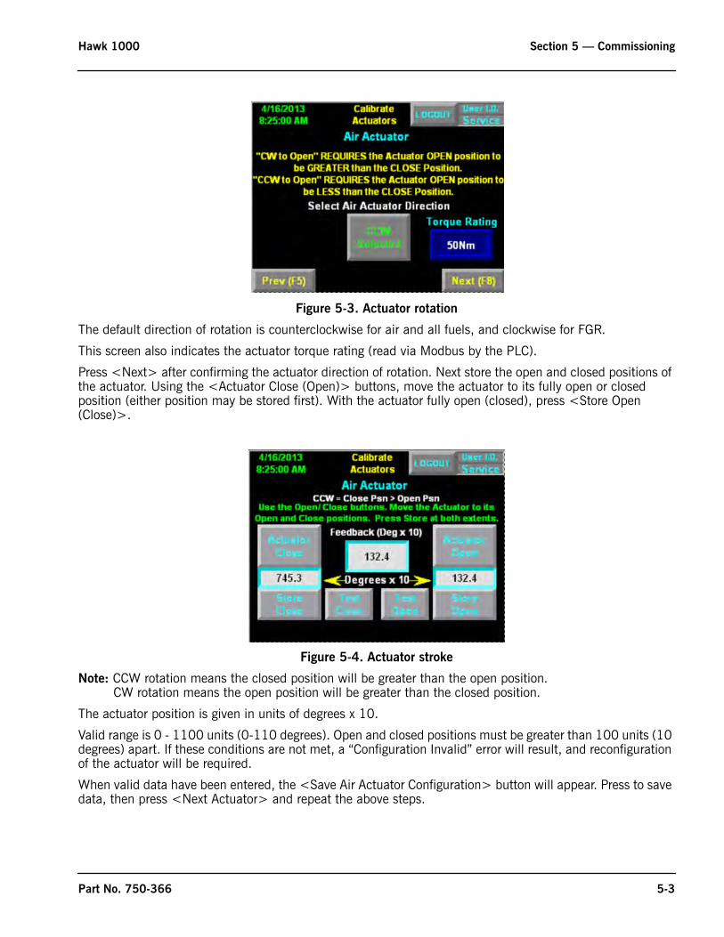
Figure 5-3. Actuator rotation
The default direction of rotation is counterclockwise for air and all fuels, and clockwise for FGR.
This screen also indicates the actuator torque rating (read via Modbus by the PLC).
Press <Next> after confirming the actuator direction of rotation. Next store the open and closed positions of the actuator. Using the <Actuator Close (Open)> buttons, move the actuator to its fully open or closed position (either position may be stored first). With the actuator fully open (closed), press <Store Open (Close)>.
Figure 5-4. Actuator stroke
Note: CCW rotation means the closed position will be greater than the open position. CW rotation means the open position will be greater than the closed position.
The actuator position is given in units of degrees x 10.
Valid range is 0 - 1100 units (0-110 degrees). Open and closed positions must be greater than 100 units (10 degrees) apart. If these conditions are not met, a “Configuration Invalid” error will result, and reconfiguration of the actuator will be required.
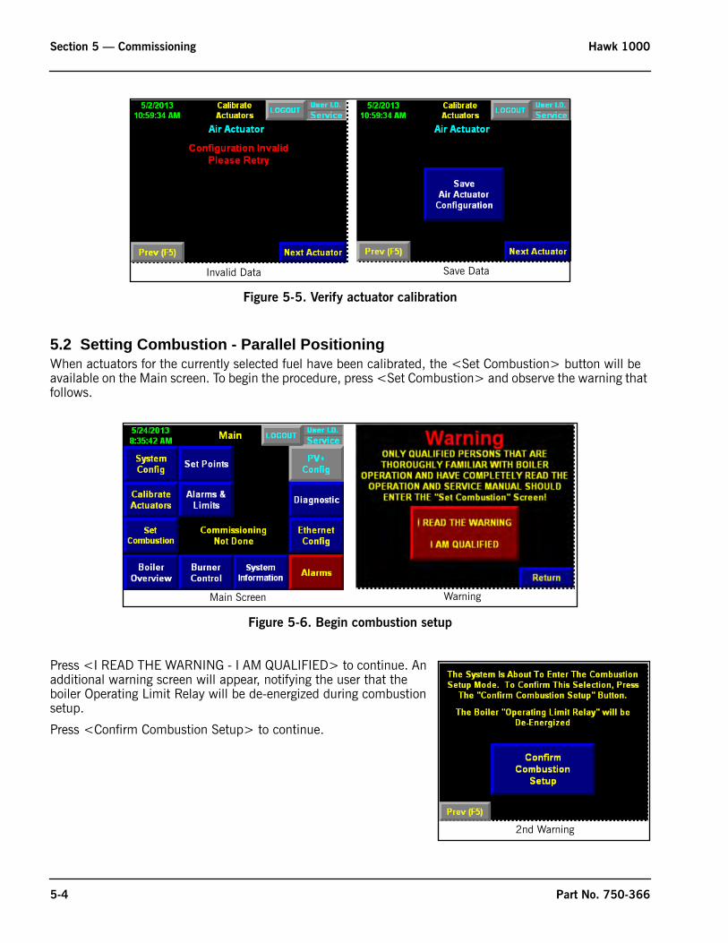
When valid data have been entered, the <Save Air Actuator Configuration> button will appear. Press to save data, then press <Next Actuator> and repeat the above steps.
Part No. 750-366 5-3
Section 5 — Commissioning Hawk 1000
Figure 5-5. Verify actuator calibration
5.2 Setting Combustion - Parallel PositioningWhen actuators for the currently selected fuel have been calibrated, the <Set Combustion> button will be available on the Main screen. To begin the procedure, press <Set Combustion> and observe the warning that follows.
Figure 5-6. Begin combustion setup
Press <I READ THE WARNING - I AM QUALIFIED> to continue. An additional warning screen will appear, notifying the user that the boiler Operating Limit Relay will be de-energized during combustion setup.
Press <Confirm Combustion Setup> to continue.
Invalid Data Save Data
Main Screen Warning
2nd Warning
5-4 Part No. 750-366
Hawk 1000 Section 5 — Commissioning
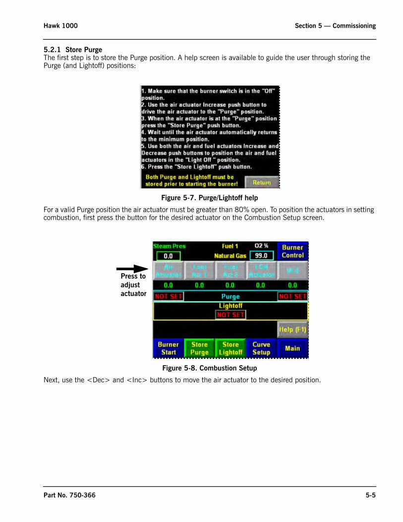
5.2.1 Store PurgeThe first step is to store the Purge position. A help screen is available to guide the user through storing the Purge (and Lightoff) positions:
Figure 5-7. Purge/Lightoff help
For a valid Purge position the air actuator must be greater than 80% open. To position the actuators in setting combustion, first press the button for the desired actuator on the Combustion Setup screen.
Figure 5-8. Combustion Setup
Next, use the <Dec> and <Inc> buttons to move the air actuator to the desired position.
Press to
adjust
actuator
Part No. 750-366 5-5
Section 5 — Commissioning Hawk 1000
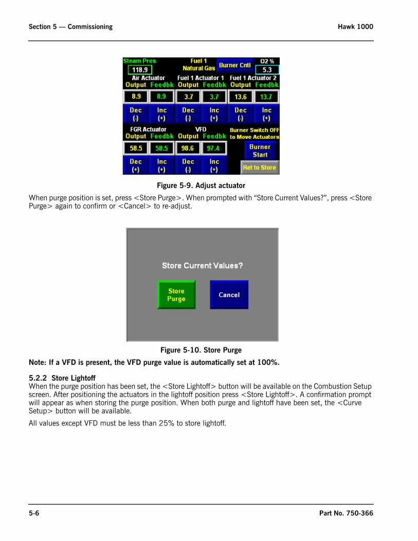
Figure 5-9. Adjust actuator
When purge position is set, press <Store Purge>. When prompted with “Store Current Values?”, press <Store Purge> again to confirm or <Cancel> to re-adjust.
Figure 5-10. Store Purge
Note: If a VFD is present, the VFD purge value is automatically set at 100%.
5.2.2 Store LightoffWhen the purge position has been set, the <Store Lightoff> button will be available on the Combustion Setup screen. After positioning the actuators in the lightoff position press <Store Lightoff>. A confirmation prompt will appear as when storing the purge position. When both purge and lightoff have been set, the <Curve Setup> button will be available.
All values except VFD must be less than 25% to store lightoff.
5-6 Part No. 750-366
Hawk 1000 Section 5 — Commissioning
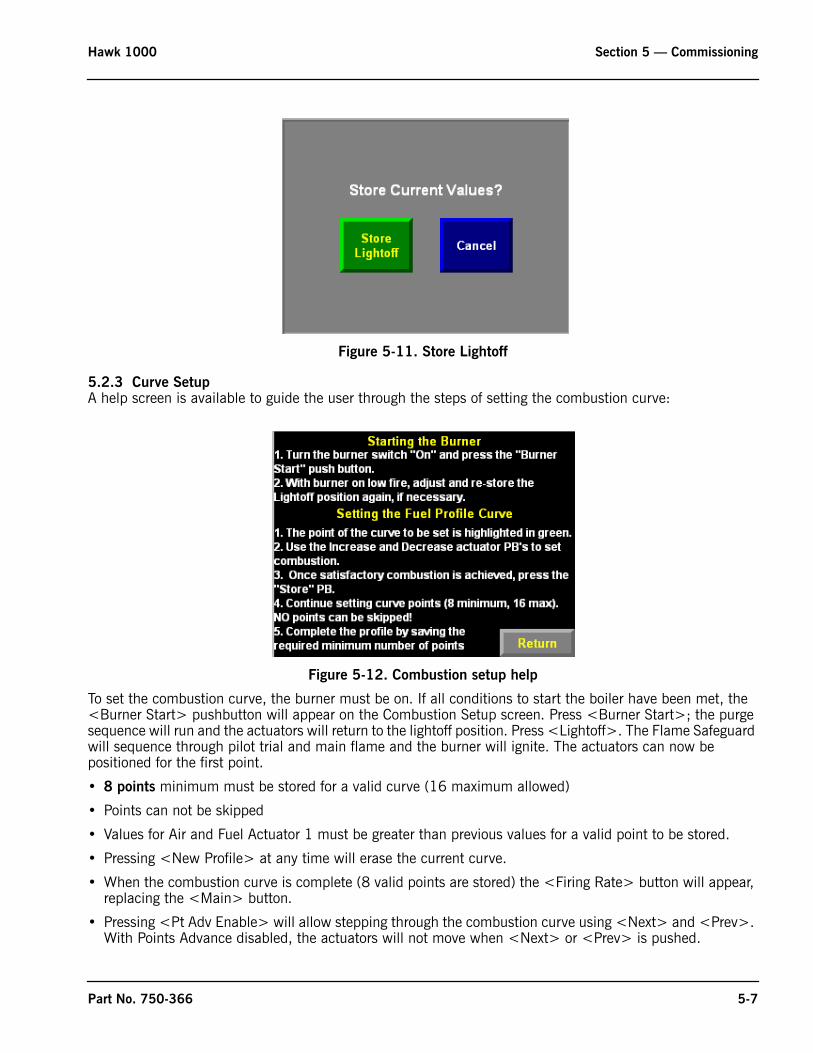
Figure 5-11. Store Lightoff
5.2.3 Curve SetupA help screen is available to guide the user through the steps of setting the combustion curve:
Figure 5-12. Combustion setup help
To set the combustion curve, the burner must be on. If all conditions to start the boiler have been met, the <Burner Start> pushbutton will appear on the Combustion Setup screen. Press <Burner Start>; the purge sequence will run and the actuators will return to the lightoff position. Press <Lightoff>. The Flame Safeguard will sequence through pilot trial and main flame and the burner will ignite. The actuators can now be positioned for the first point.
• 8 points minimum must be stored for a valid curve (16 maximum allowed)
• Points can not be skipped
• Values for Air and Fuel Actuator 1 must be greater than previous values for a valid point to be stored.
• Pressing <New Profile> at any time will erase the current curve.
• When the combustion curve is complete (8 valid points are stored) the <Firing Rate> button will appear, replacing the <Main> button.
• Pressing <Pt Adv Enable> will allow stepping through the combustion curve using <Next> and <Prev>. With Points Advance disabled, the actuators will not move when <Next> or <Prev> is pushed.
Part No. 750-366 5-7
Section 5 — Commissioning Hawk 1000
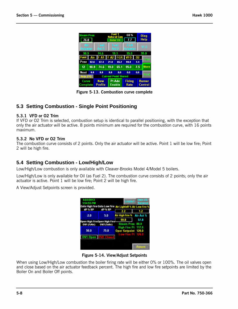
Figure 5-13. Combustion curve complete
5.3 Setting Combustion - Single Point Positioning
5.3.1 VFD or O2 TrimIf VFD or O2 Trim is selected, combustion setup is identical to parallel positioning, with the exception that only the air actuator will be active. 8 points minimum are required for the combustion curve, with 16 points maximum.
5.3.2 No VFD or O2 TrimThe combustion curve consists of 2 points. Only the air actuator will be active. Point 1 will be low fire; Point 2 will be high fire.
5.4 Setting Combustion - Low/High/LowLow/High/Low combustion is only available with Cleaver-Brooks Model 4/Model 5 boilers.
Low/High/Low is only available for Oil (as Fuel 2). The combustion curve consists of 2 points; only the air actuator is active. Point 1 will be low fire; Point 2 will be high fire.
A View/Adjust Setpoints screen is provided.
Figure 5-14. View/Adjust Setpoints
When using Low/High/Low combustion the boiler firing rate will be either 0% or 100%. The oil valves open and close based on the air actuator feedback percent. The high fire and low fire setpoints are limited by the Boiler On and Boiler Off points.
5-8 Part No. 750-366
Hawk 1000 Section 5 — Commissioning
When steam pressure is greater than the low fire point, the firing rate will go to 0%.
When steam pressure is less than the high fire point, the firing rate will go to 100%.
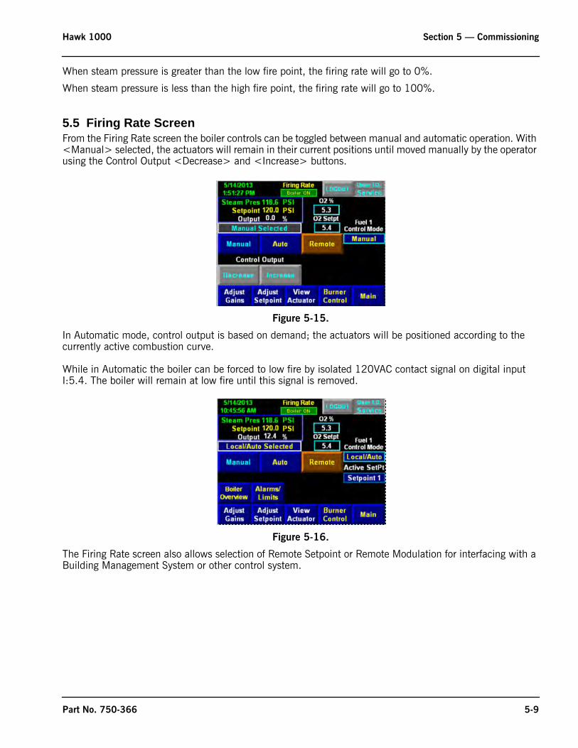
5.5 Firing Rate ScreenFrom the Firing Rate screen the boiler controls can be toggled between manual and automatic operation. With <Manual> selected, the actuators will remain in their current positions until moved manually by the operator using the Control Output <Decrease> and <Increase> buttons.
Figure 5-15.
In Automatic mode, control output is based on demand; the actuators will be positioned according to the currently active combustion curve.
While in Automatic the boiler can be forced to low fire by isolated 120VAC contact signal on digital input I:5.4. The boiler will remain at low fire until this signal is removed.
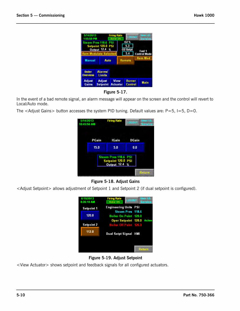
Figure 5-16.
The Firing Rate screen also allows selection of Remote Setpoint or Remote Modulation for interfacing with a Building Management System or other control system.
Part No. 750-366 5-9
Section 5 — Commissioning Hawk 1000
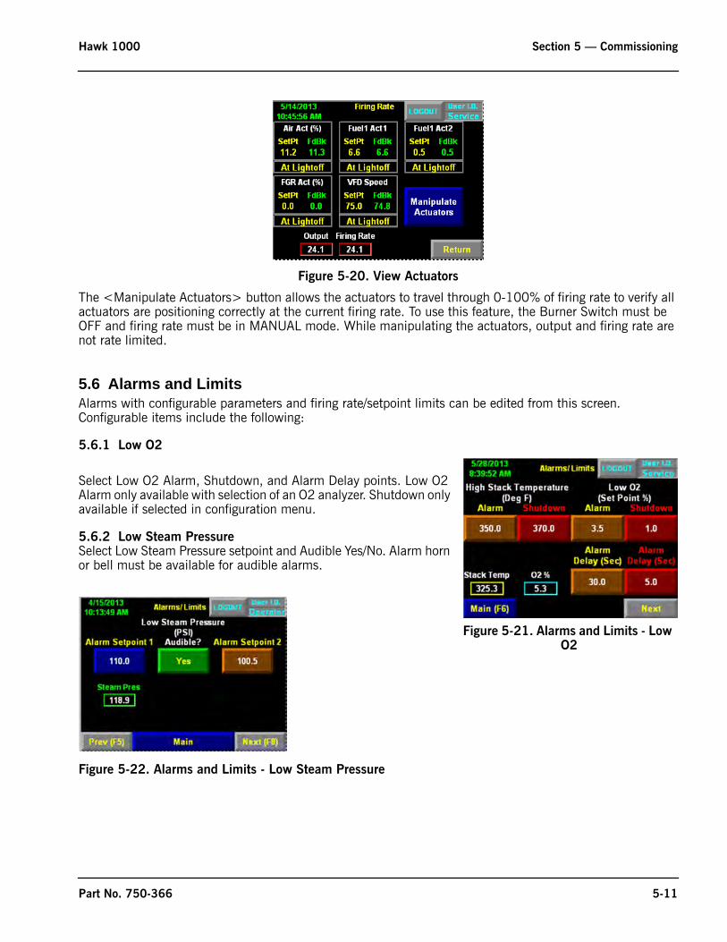
Figure 5-17.
In the event of a bad remote signal, an alarm message will appear on the screen and the control will revert to Local/Auto mode.
The <Adjust Gains> button accesses the system PID tuning. Default values are: P=5, I=5, D=0.
Figure 5-18. Adjust Gains
<Adjust Setpoint> allows adjustment of Setpoint 1 and Setpoint 2 (if dual setpoint is configured).
Figure 5-19. Adjust Setpoint
<View Actuator> shows setpoint and feedback signals for all configured actuators.
5-10 Part No. 750-366
Hawk 1000 Section 5 — Commissioning
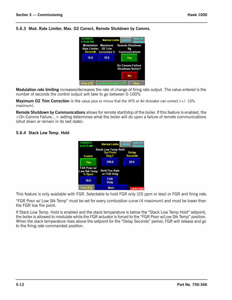
Figure 5-20. View Actuators
The <Manipulate Actuators> button allows the actuators to travel through 0-100% of firing rate to verify all actuators are positioning correctly at the current firing rate. To use this feature, the Burner Switch must be OFF and firing rate must be in MANUAL mode. While manipulating the actuators, output and firing rate are not rate limited.
5.6 Alarms and LimitsAlarms with configurable parameters and firing rate/setpoint limits can be edited from this screen. Configurable items include the following:
5.6.1 Low O2
Select Low O2 Alarm, Shutdown, and Alarm Delay points. Low O2 Alarm only available with selection of an O2 analyzer. Shutdown only available if selected in configuration menu.
5.6.2 Low Steam PressureSelect Low Steam Pressure setpoint and Audible Yes/No. Alarm horn or bell must be available for audible alarms.
Figure 5-22. Alarms and Limits - Low Steam Pressure
Figure 5-21. Alarms and Limits - Low O2
Part No. 750-366 5-11
Section 5 — Commissioning Hawk 1000
5.6.3 Mod. Rate Limiter, Max. O2 Correct, Remote Shutdown by Comms.
Modulation rate limiting increases/decreases the rate of change of firing rate output. The value entered is the number of seconds the control output will take to go between 0-100%
Maximum O2 Trim Correction is the value plus or minus that the VFD or Air Actuator can correct (+/- 10% maximum).
Remote Shutdown by Communications allows for remote start/stop of the boiler. If this feature is enabled, the <On Comms Failure...> setting determines what the boiler will do upon a failure of remote communications (shut down or remain in its last state).
5.6.4 Stack Low Temp. Hold
This feature is only available with FGR. Selectable to hold FGR only (20 ppm or less) or FGR and firing rate.
“FGR Posn w/ Low Stk Temp” must be set for every combustion curve (4 maximum) and must be lower than the FGR low fire point.
If Stack Low Temp. Hold is enabled and the stack temperature is below the “Stack Low Temp Hold” setpoint, the boiler is allowed to modulate while the FGR actuator is forced to the “FGR Posn w/Low Stk Temp” position. When the stack temperature rises above the setpoint for the “Delay Seconds” period, FGR will release and go to the firing rate commanded position.
5-12 Part No. 750-366
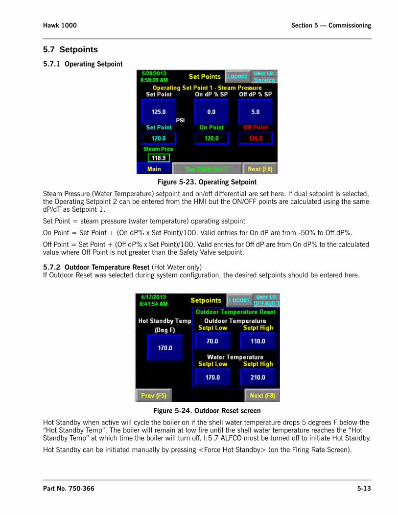
Hawk 1000 Section 5 — Commissioning
5.7 Setpoints5.7.1 Operating Setpoint
Figure 5-23. Operating Setpoint
Steam Pressure (Water Temperature) setpoint and on/off differential are set here. If dual setpoint is selected, the Operating Setpoint 2 can be entered from the HMI but the ON/OFF points are calculated using the same dP/dT as Setpoint 1.
Set Point = steam pressure (water temperature) operating setpoint
On Point = Set Point + (On dP% x Set Point)/100. Valid entries for On dP are from -50% to Off dP%.
Off Point = Set Point + (Off dP% x Set Point)/100. Valid entries for Off dP are from On dP% to the calculated value where Off Point is not greater than the Safety Valve setpoint.
5.7.2 Outdoor Temperature Reset (Hot Water only)If Outdoor Reset was selected during system configuration, the desired setpoints should be entered here.
Figure 5-24. Outdoor Reset screen
Hot Standby when active will cycle the boiler on if the shell water temperature drops 5 degrees F below the “Hot Standby Temp”. The boiler will remain at low fire until the shell water temperature reaches the “Hot Standby Temp” at which time the boiler will turn off. I:5.7 ALFCO must be turned off to initiate Hot Standby.
Hot Standby can be initiated manually by pressing <Force Hot Standby> (on the Firing Rate Screen).
Part No. 750-366 5-13
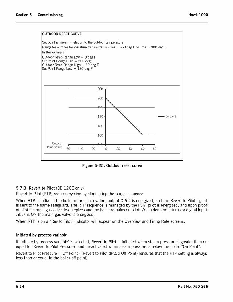
Section 5 — Commissioning Hawk 1000
Figure 5-25. Outdoor reset curve
5.7.3 Revert to Pilot (CB 120E only)Revert to Pilot (RTP) reduces cycling by eliminating the purge sequence.
When RTP is initiated the boiler returns to low fire, output O:6.4 is energized, and the Revert to Pilot signal is sent to the flame safeguard. The RTP sequence is managed by the FSG: pilot is energized, and upon proof of pilot the main gas valve de-energizes and the boiler remains on pilot. When demand returns or digital input J:5.7 is ON the main gas valve is energized.
When RTP is on a “Rev to Pilot” indicator will appear on the Overview and Firing Rate screens.
Initiated by process variable
If ‘Initiate by process variable’ is selected, Revert to Pilot is initiated when steam pressure is greater than or equal to “Revert to Pilot Pressure” and de-activated when steam pressure is below the boiler “On Point”.
Revert to Pilot Pressure = Off Point - (Revert to Pilot dP% x Off Point) [ensures that the RTP setting is always less than or equal to the boiler off point]
-60 -40 -20 0 20 40 60 80175
180
185
190
195
200
205
Setpoint
OutdoorTemperature
OUTDOOR RESET CURVE
Set point is linear in relation to the outdoor temperature.Range for outdoor temperature transmitter is 4 ma = -50 deg F, 20 ma = 900 deg F.In this example:Outdoor Temp Range Low = 0 deg FSet Point Range High = 200 deg FOutdoor Temp Range High = 60 deg FSet Point Range Low = 180 deg F
5-14 Part No. 750-366
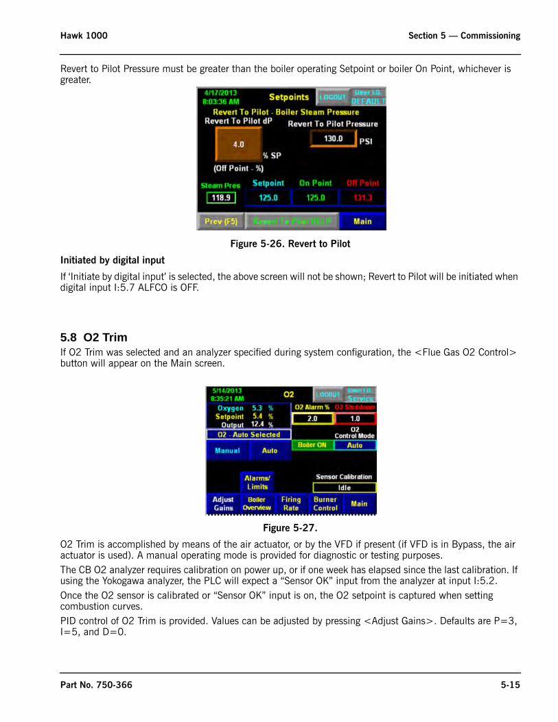
Hawk 1000 Section 5 — Commissioning
Revert to Pilot Pressure must be greater than the boiler operating Setpoint or boiler On Point, whichever is greater.
Figure 5-26. Revert to Pilot
Initiated by digital input
If ‘Initiate by digital input’ is selected, the above screen will not be shown; Revert to Pilot will be initiated when digital input I:5.7 ALFCO is OFF.
5.8 O2 TrimIf O2 Trim was selected and an analyzer specified during system configuration, the <Flue Gas O2 Control> button will appear on the Main screen.
Figure 5-27.
O2 Trim is accomplished by means of the air actuator, or by the VFD if present (if VFD is in Bypass, the air actuator is used). A manual operating mode is provided for diagnostic or testing purposes.The CB O2 analyzer requires calibration on power up, or if one week has elapsed since the last calibration. If using the Yokogawa analyzer, the PLC will expect a “Sensor OK” input from the analyzer at input I:5.2.Once the O2 sensor is calibrated or “Sensor OK” input is on, the O2 setpoint is captured when setting combustion curves.PID control of O2 Trim is provided. Values can be adjusted by pressing <Adjust Gains>. Defaults are P=3, I=5, and D=0.
Part No. 750-366 5-15
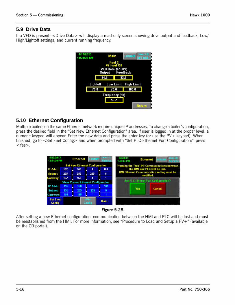
Section 5 — Commissioning Hawk 1000
5.9 Drive DataIf a VFD is present, <Drive Data> will display a read-only screen showing drive output and feedback, Low/High/Lightoff settings, and current running frequency.
5.10 Ethernet ConfigurationMultiple boilers on the same Ethernet network require unique IP addresses. To change a boiler’s configuration, press the desired field in the “Set New Ethernet Configuration” area. If user is logged in at the proper level, a numeric keypad will appear. Enter the new data and press the enter key (or use the PV+ keypad). When finished, go to <Set Enet Config> and when prompted with “Set PLC Ethernet Port Configuration?” press <Yes>.
Figure 5-28.
After setting a new Ethernet configuration, communication between the HMI and PLC will be lost and must be reestablished from the HMI. For more information, see “Procedure to Load and Setup a PV+” (available on the CB portal).
5-16 Part No. 750-366
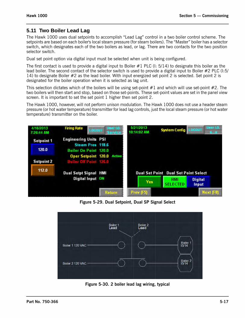
Hawk 1000 Section 5 — Commissioning
5.11 Two Boiler Lead LagThe Hawk 1000 uses dual setpoints to accomplish “Lead Lag” control in a two boiler control scheme. The setpoints are based on each boiler's local steam pressure (for steam boilers). The “Master” boiler has a selector switch, which designates each of the two boilers as lead, or lag. There are two contacts for the two position selector switch.
Dual set point option via digital input must be selected when unit is being configured.
The first contact is used to provide a digital input to Boiler #1 PLC (I: 5/14) to designate this boiler as the lead boiler. The second contact of the selector switch is used to provide a digital input to Boiler #2 PLC (I:5/14) to designate Boiler #2 as the lead boiler. With input energized set point 2 is selected. Set point 2 is designated for the boiler operation when it is selected as lag unit.
This selection dictates which of the boilers will be using set-point #1 and which will use set-point #2. The two boilers will then start and stop, based on those set-points. These set-point values are set in the panel view screen. It is important to set the set point 1 higher then set point 2.
The Hawk 1000, however, will not perform unison modulation. The Hawk 1000 does not use a header steam pressure (or hot water temperature) transmitter for lead lag controls, just the local steam pressure (or hot water temperature) transmitter on the boiler.
Figure 5-29. Dual Setpoint, Dual SP Signal Select
Figure 5-30. 2 boiler lead lag wiring, typical
Part No. 750-366 5-17
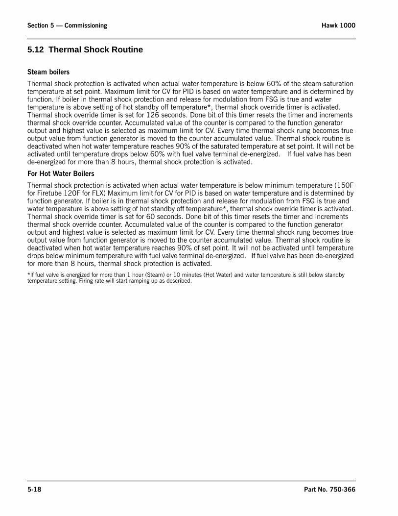
Section 5 — Commissioning Hawk 1000
5.12 Thermal Shock Routine
Steam boilers
Thermal shock protection is activated when actual water temperature is below 60% of the steam saturation temperature at set point. Maximum limit for CV for PID is based on water temperature and is determined by function. If boiler in thermal shock protection and release for modulation from FSG is true and water temperature is above setting of hot standby off temperature*, thermal shock override timer is activated. Thermal shock override timer is set for 126 seconds. Done bit of this timer resets the timer and increments thermal shock override counter. Accumulated value of the counter is compared to the function generator output and highest value is selected as maximum limit for CV. Every time thermal shock rung becomes true output value from function generator is moved to the counter accumulated value. Thermal shock routine is deactivated when hot water temperature reaches 90% of the saturated temperature at set point. It will not be activated until temperature drops below 60% with fuel valve terminal de-energized. If fuel valve has been de-energized for more than 8 hours, thermal shock protection is activated.
For Hot Water Boilers
Thermal shock protection is activated when actual water temperature is below minimum temperature (150F for Firetube 120F for FLX) Maximum limit for CV for PID is based on water temperature and is determined by function generator. If boiler is in thermal shock protection and release for modulation from FSG is true and water temperature is above setting of hot standby off temperature*, thermal shock override timer is activated. Thermal shock override timer is set for 60 seconds. Done bit of this timer resets the timer and increments thermal shock override counter. Accumulated value of the counter is compared to the function generator output and highest value is selected as maximum limit for CV. Every time thermal shock rung becomes true output value from function generator is moved to the counter accumulated value. Thermal shock routine is deactivated when hot water temperature reaches 90% of set point. It will not be activated until temperature drops below minimum temperature with fuel valve terminal de-energized. If fuel valve has been de-energized for more than 8 hours, thermal shock protection is activated.
*If fuel valve is energized for more than 1 hour (Steam) or 10 minutes (Hot Water) and water temperature is still below standby temperature setting. Firing rate will start ramping up as described.
5-18 Part No. 750-366

www.cleaverbrooks.com
Section 6Diagnostics and Troubleshooting
System Monitoring and Diagnostics . . . . . . . . . . . . . . . . . . . . . . . . . . . . . 6-2Boiler Overview . . . . . . . . . . . . . . . . . . . . . . . . . . . . . . . . . . . 6-2Burner Control . . . . . . . . . . . . . . . . . . . . . . . . . . . . . . . . . . . . 6-2System Information . . . . . . . . . . . . . . . . . . . . . . . . . . . . . . . . . 6-3PLC Info . . . . . . . . . . . . . . . . . . . . . . . . . . . . . . . . . . . . . . . . 6-3Diagnostic Screens . . . . . . . . . . . . . . . . . . . . . . . . . . . . . . . . . 6-4
PLC Status. . . . . . . . . . . . . . . . . . . . . . . . . . . . . . . . . . . . . . . . . . . . . . . 6-4
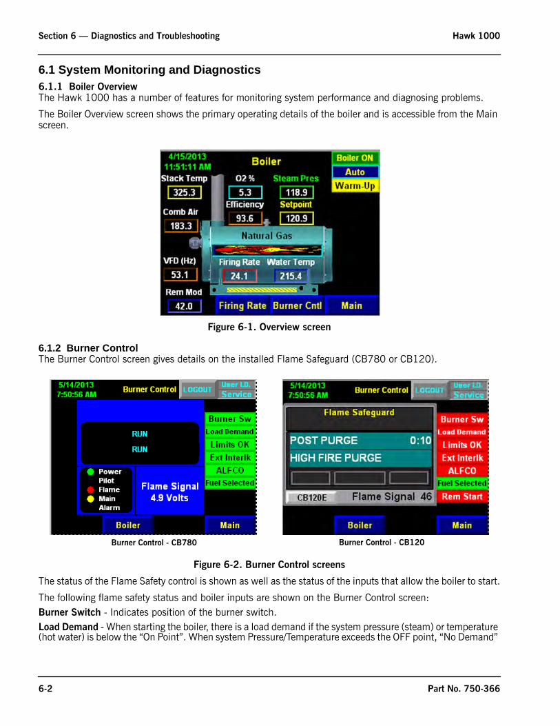
Section 6 — Diagnostics and Troubleshooting Hawk 1000
6.1 System Monitoring and Diagnostics6.1.1 Boiler OverviewThe Hawk 1000 has a number of features for monitoring system performance and diagnosing problems.
The Boiler Overview screen shows the primary operating details of the boiler and is accessible from the Main screen.
Figure 6-1. Overview screen
6.1.2 Burner ControlThe Burner Control screen gives details on the installed Flame Safeguard (CB780 or CB120).
Figure 6-2. Burner Control screens
The status of the Flame Safety control is shown as well as the status of the inputs that allow the boiler to start.
The following flame safety status and boiler inputs are shown on the Burner Control screen:Burner Switch - Indicates position of the burner switch.Load Demand - When starting the boiler, there is a load demand if the system pressure (steam) or temperature (hot water) is below the “On Point”. When system Pressure/Temperature exceeds the OFF point, “No Demand”
Burner Control - CB780 Burner Control - CB120
6-2 Part No. 750-366
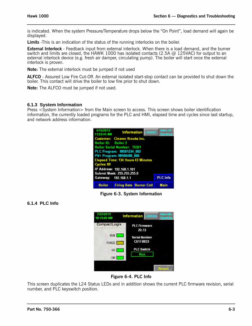
Hawk 1000 Section 6 — Diagnostics and Troubleshooting
is indicated. When the system Pressure/Temperature drops below the “On Point”, load demand will again be displayed.Limits -This is an indication of the status of the running interlocks on the boiler. External Interlock - Feedback input from external interlock. When there is a load demand, and the burner switch and limits are closed, the HAWK 1000 has isolated contacts (2.5A @ 125VAC) for output to an external interlock device (e.g. fresh air damper, circulating pump). The boiler will start once the external interlock is proven.
Note: The external interlock must be jumped if not used
ALFCO - Assured Low Fire Cut-Off. An external isolated start-stop contact can be provided to shut down the boiler. This contact will drive the boiler to low fire prior to shut down.Note: The ALFCO must be jumped if not used.
6.1.3 System InformationPress <System Information> from the Main screen to access. This screen shows boiler identification information, the currently loaded programs for the PLC and HMI, elapsed time and cycles since last startup, and network address information.
Figure 6-3. System Information
6.1.4 PLC Info
Figure 6-4. PLC Info
This screen duplicates the L24 Status LEDs and in addition shows the current PLC firmware revision, serial number, and PLC keyswitch position.
Part No. 750-366 6-3
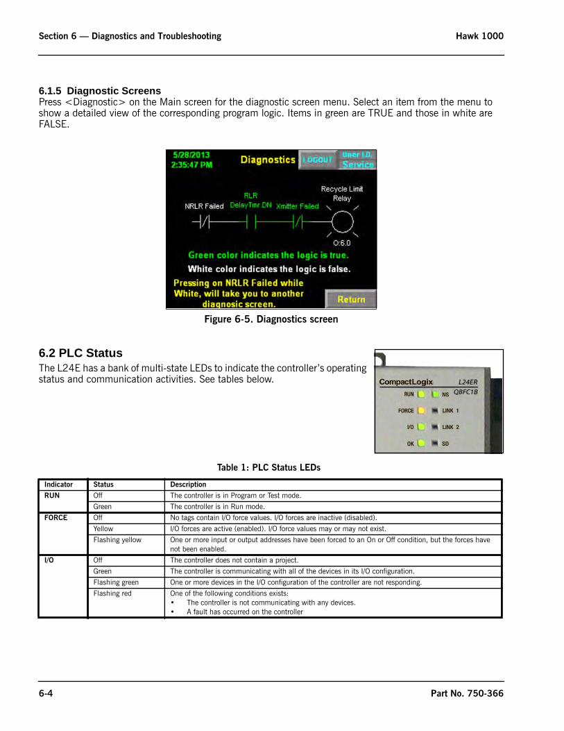
Section 6 — Diagnostics and Troubleshooting Hawk 1000
6.1.5 Diagnostic ScreensPress <Diagnostic> on the Main screen for the diagnostic screen menu. Select an item from the menu to show a detailed view of the corresponding program logic. Items in green are TRUE and those in white are FALSE.
6.2 PLC Status The L24E has a bank of multi-state LEDs to indicate the controller’s operating status and communication activities. See tables below.
Figure 6-5. Diagnostics screen
Table 1: PLC Status LEDs
Indicator Status Description
RUN Off The controller is in Program or Test mode.
Green The controller is in Run mode.
FORCE Off No tags contain I/O force values. I/O forces are inactive (disabled).
Yellow I/O forces are active (enabled). I/O force values may or may not exist.
Flashing yellow One or more input or output addresses have been forced to an On or Off condition, but the forces have not been enabled.
I/O Off The controller does not contain a project.
Green The controller is communicating with all of the devices in its I/O configuration.
Flashing green One or more devices in the I/O configuration of the controller are not responding.
Flashing red One of the following conditions exists:• The controller is not communicating with any devices.• A fault has occurred on the controller
6-4 Part No. 750-366
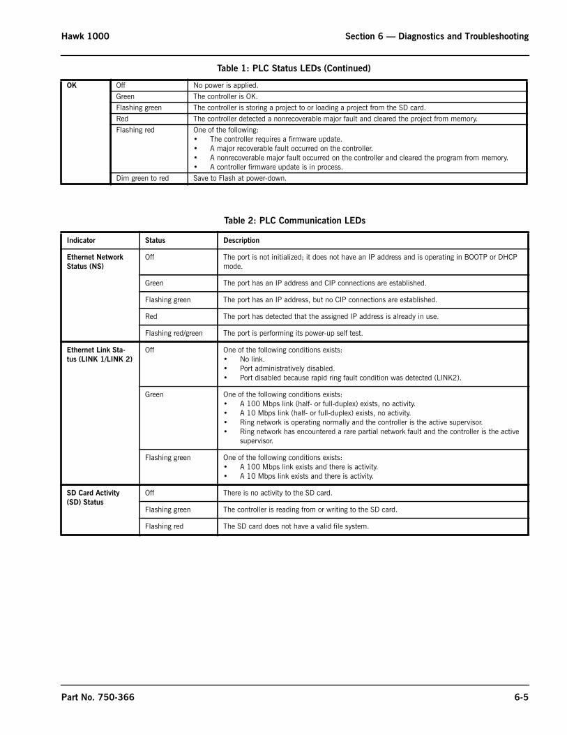
Hawk 1000 Section 6 — Diagnostics and Troubleshooting
OK Off No power is applied.
Green The controller is OK.
Flashing green The controller is storing a project to or loading a project from the SD card.
Red The controller detected a nonrecoverable major fault and cleared the project from memory.
Flashing red One of the following:• The controller requires a firmware update.• A major recoverable fault occurred on the controller.• A nonrecoverable major fault occurred on the controller and cleared the program from memory. • A controller firmware update is in process.
Dim green to red Save to Flash at power-down.
Table 2: PLC Communication LEDs
Indicator Status Description
Ethernet Network
Status (NS)
Off The port is not initialized; it does not have an IP address and is operating in BOOTP or DHCP mode.
Green The port has an IP address and CIP connections are established.
Flashing green The port has an IP address, but no CIP connections are established.
Red The port has detected that the assigned IP address is already in use.
Flashing red/green The port is performing its power-up self test.
Ethernet Link Sta-
tus (LINK 1/LINK 2)
Off One of the following conditions exists:• No link.• Port administratively disabled.• Port disabled because rapid ring fault condition was detected (LINK2).
Green One of the following conditions exists:• A 100 Mbps link (half- or full-duplex) exists, no activity.• A 10 Mbps link (half- or full-duplex) exists, no activity.• Ring network is operating normally and the controller is the active supervisor.• Ring network has encountered a rare partial network fault and the controller is the active
supervisor.
Flashing green One of the following conditions exists:• A 100 Mbps link exists and there is activity.• A 10 Mbps link exists and there is activity.
SD Card Activity
(SD) Status
Off There is no activity to the SD card.
Flashing green The controller is reading from or writing to the SD card.
Flashing red The SD card does not have a valid file system.
Table 1: PLC Status LEDs (Continued)
Part No. 750-366 6-5

Section 6 — Diagnostics and Troubleshooting Hawk 1000
6-6 Part No. 750-366
Section 7Parts
PLC, I/O, HMI
ACTUATORS
Qty Part Number Description
1 880-06082-000 Hawk 1000 Kit - must be ordered as complete kit only
1 833-10039-000 PLC Processor
1 833-10040-000 4 Inch PV+ Compact Touch Screen with (118-04514-000 label included)
1 833-02842-000 Digital Input Module
1 833-02872-000 Relay Module
1 833-03099-000 Modbus Module SM2
2 826-00111-000 Ethernet Cable
1 832-02404-000 Power Supply120 Watt, (For PLC, PV + & Analog Inputs)
1 832-02037-000 Power Supply 50 Watt (For Modbus) Use 120 Watt for 50NM Actuator
1 848-01623-000 Centre 60x30x10, No Cut outs (Conversions uses a different size)
1 983-00083-000 6 Amp
1 836-00620-000 Qty 1 (add another if oil heater for #6 oil is required)
1 118-03173-000 4” x 16”
1 001-01476-000 Orion, OA109-12POT/DIN
1 817-00239-000 Alarm Bell
Qty Part Number Description
1 945-00259-000 Modbus FX04-1, 3 ft-lb (4 N-m) (Use on Fuel and FGR valves, except in High Torque applications)
1 945-00260-000 Modbus FX20-1, 15 ft-lb (20 N-m) (Use On Combustion Air Damper, except in High Torque applications)
1 945-00261-000 Modbus FX50-1, 37 ft-lb (50 N-m)
600” 826-00205-000 Cable, 5 conductor,18 AWG
826-00206-000 Connector, female, straight, 7/8” screw connection - Two required per actuator
www.cleaverbrooks.com
Section 7 — Parts Hawk 1000
MISC.
FSG
Qty Part Number Description
1 833-02835-000 1769-IF4 Analog Current Input Module (req. w/ O2 Trim, VFD, or Combustion Air Temp option)
1 833-10116-000 9300-ENA Ethernet Appliance Router
1 817-05166-000 Temperature Sensor, 8" Probe, -50-900 Deg F
1 833-09181-000 Ethernet Switch, Rockwell Stratix 5 Port, 1783-US05T
1 833-09163-000 Ethernet Switch, Rockwell Stratix, 8 Port, 1783-US08T
1
1 817-05166-000 Temperature Sensor, 8" Probe, -50-900 Deg F
1 008-02998-000 Transmitter mounting, Outdoor Reset
1 836-00627-000 Bundled Kit - Gas Oil Selector
Qty Part Number Description
880-02117-000 CB-780E w / IR Scanner Kit
1 833-03517-000 CB-780E Programmer
1 833-02725-000 Wiring Sub-Base
1 833-03495-000 Infared Amplifier
1 833-02730-000 Purge Timer Card
1 817-04133-000 Scanner IR 817-1742
880-02118-000 CB-780E w / UV Scanner Kit
1 833-03517-000 CB-780E Programmer
1 833-02725-000 Wiring Sub-Base
1 833-02724-000 U.V. Amplifier
1 833-02730-000 Purge Timer Card
1 817-01743-000 Flame Detector UV
880-02097-000 CB-120E w / IR Scanner Kit
1 833-03708-000 Chassis/Amplifier
1 833-03153-000 Wiring Sub-Base open with terminal block
1 833-03143-000 Programmer
1 833-03151-000 Display
1 833-03516-000 ED-512 communications cable 4 foot long
1 817-01933-000 IR Scanner 817-2261
880-02096-000 CB-120E w / UV Scanner Kit
1 833-03135-000 Chassis/Amplifier
1 833-03153-000 Wiring Sub-Base open with terminal block
1 833-03143-000 Programmer
1 833-03151-000 Display
1 833-03516-000 ED-512 communications cable 4 foot long
1 817-02262-000 UV Detector
7-2 Part No. 750-366
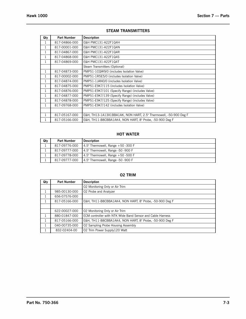
Hawk 1000 Section 7 — Parts
STEAM TRANSMITTERS
HOT WATER
O2 TRIM
Qty Part Number Description
1 817-04866-000 E&H PMC131-A22F1Q4H
1 817-00001-000 E&H PMC131-A22F1Q4N
1 817-04867-000 E&H PMC131-A22F1Q4R
1 817-04868-000 E&H PMC131-A22F1Q4S
1 817-04869-000 E&H PMC131-A22F1Q4T
Steam Transmitters (Optional)
1 817-04873-000 PMP51-1CQW9/0 (includes Isolation Valve)
1 817-00002-000 PMP51-1R5E5/0 (includes Isolation Valve)
1 817-04874-000 PMP51-1JAN0/0 (includes Isolation Valve)
1 817-04875-000 PMP51-E9K7/115 (includes Isolation Valve)
1 817-04876-000 PMP51-E9K7/101 (Specify Range) (includes Valve)
1 817-04877-000 PMP51-E9K7/139 (Specify Range) (includes Valve)
1 817-04878-000 PMP51-E9K7/125 (Specify Range) (includes Valve)
1 817-09768-000 PMP51-E9K7/142 (includes Isolation Valve)
1 817-05167-000 E&H, TH13-1A13X1BBA1AK, NON HART, 2.5" Thermowell, -50-900 Deg F
1 817-05166-000 E&H, TH11-B8CBBA1AK4, NON HART, 8" Probe, -50-900 Deg F
Qty Part Number Description
1 817-09776-000 4.5" Thermowell, Range +50 -300 F
1 817-09777-000 4.5" Thermowell, Range -50 -900 F
1 817-09778-000 4.5" Thermowell, Range +50 -500 F
1 817-09777-000 4.5" Thermowell, Range -50 -900 F
Qty Part Number Description
O2 Monitoring Only or Air Trim
1 985-00130-000 O2 Probe and Analyzer
1 656-07576-000
1 817-05166-000 E&H, TH11-B8CBBA1AK4, NON HART, 8" Probe, -50-900 Deg F
622-00027-000 O2 Monitoring Only or Air Trim
1 880-01847-000 ECM controller with NTK Wide Band Sensor and Cable Harness
1 817-05166-000 E&H, TH11-B8CBBA1AK4, NON HART, 8" Probe, -50-900 Deg F
1 040-00735-000 O2 Sampling Probe Housing Assembly
1 832-02404-00 O2 Trim Power Supply120 Watt
Part No. 750-366 7-3

Section 7 — Parts Hawk 1000
7-4 Part No. 750-366