Embed Size (px)
Citation preview

630
CAD drawing data catalogis available.
VALVES GENERAL CATALOG
INDEX
SOLENOID VALVESSERIES
Before use, be sure to read the “Safety Precautions” on p. 31.Caution
SOLE
NOID
VAL
VES
240
SERI
ESFeatures 631Basic Models and Configuration 633Specifications 635Solenoid Valve, Air-piloted Valve Order Codes 637Manifold Order Codes 638Manifold for Serial Transmission System Order Codes 639Operating Principles and Major Parts 640Dimensions of Solenoid Valve 641Dimensions of Manifold 646Dimensions of Serial Transmission System 649Made to Order 651Handling Instructions and Precautions 656

631
Koganei, which has always suppliedproducts compatible with customerneeds, has recently developed the 240series valves in response to worksiterequirements. The 240 series valvesare suitable for operating mid-sizedcylinders of bore sizes 63mm [2.480in.]to 100mm [3.937in.], and offer everyrequired function. In addition to 5-port2-position types, closed center andexhaust center 3-position valves areincluded in the product range.Serial transmission modules, whichare compatible with connectingdirectly to various manufacturers’ PCs, are also included in the productvariations.The series realizes optimum systemdesign, offering space saving as wellas reducing wiring and piping work.
One-touch connect /disconnectPlug-In Connector for WiringConnectionsA plug-in connector is available for wiring connections betweenthe solenoid valve and sub-base, as well as between the solenoidvalve and manifold, so that you can remove the solenoid valvewithout disturbing the wiring portion.
Easy to increase or decrease the numberof manifold unitsStacking Type ManifoldYou can increase or decrease the number of manifold unitseasily due to the individual manifold construction using eachsolenoid valve mounted unit.You can stock manifold bases as single units, thereby offeringyou a reduction in stocking costs.
SERIES
SOLENOID VALVES
Multiple Application Systems for
632
SOLE
NOID
VAL
VES
240
SERI
ES
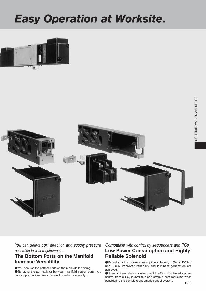
You can select port direction and supply pressureaccording to your requirements.The Bottom Ports on the ManifoldIncrease Versatility.You can use the bottom ports on the manifold for piping.By using the port isolator between manifold station ports, youcan supply multiple pressures on 1 manifold assembly.
Compatible with control by sequencers and PCsLow Power Consumption and HighlyReliable SolenoidBy using a low power consumption solenoid, 1.6W at DC24Vand 65mA, improved reliability and low heat generation areachieved.A serial transmission system, which offers distributed systemcontrol from a PC, is available and offers a cost reduction whenconsidering the complete pneumatic control system.
Easy Operation at Worksite.
Dire
ctpi
ping
Sta
ndar
dsu
b-ba
sepi
ping
Plu
g-in
sub-
base
pipi
ng
5-port
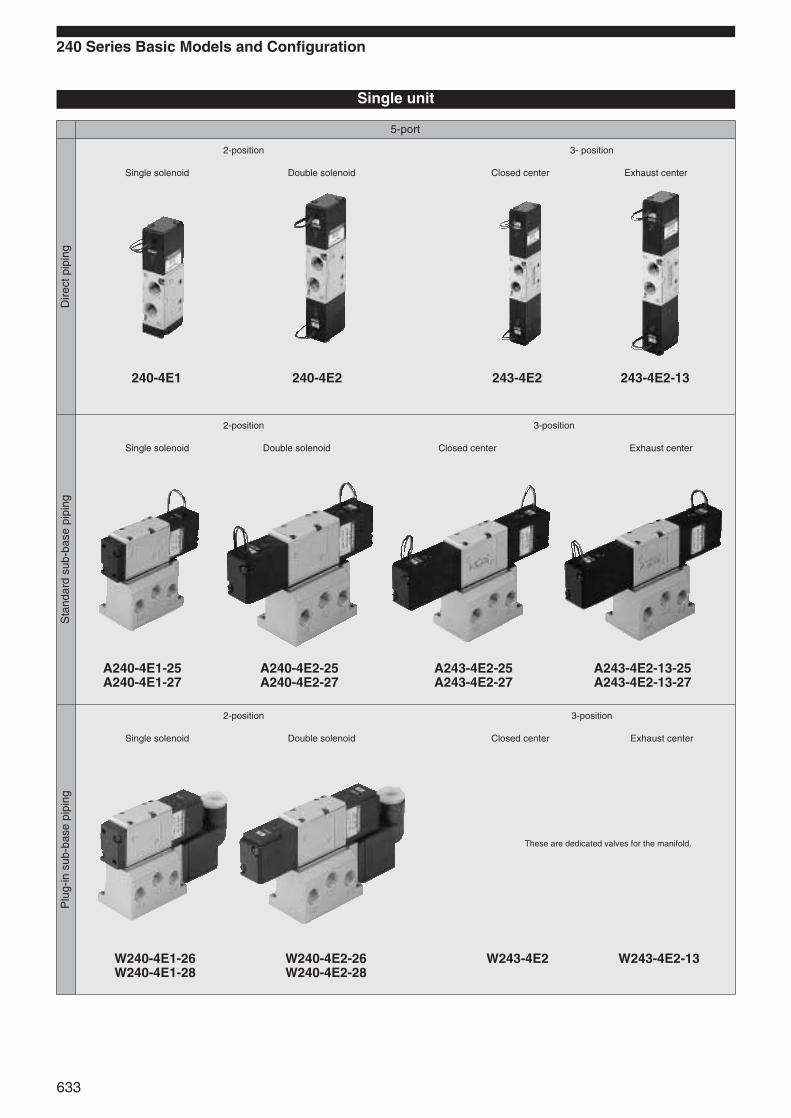
240 Series Basic Models and Configuration
Single unit
Single solenoid Double solenoid
240-4E1 240-4E2 243-4E2 243-4E2-13
2-position
Closed center Exhaust center
3- position
Single solenoid Double solenoid
A240-4E1-25A240-4E1-27
A240-4E2-25A240-4E2-27
A243-4E2-25A243-4E2-27
A243-4E2-13-25A243-4E2-13-27
2-position
Closed center Exhaust center
3-position
Single solenoid Double solenoid
W240-4E1-26W240-4E1-28
W240-4E2-26W240-4E2-28
W243-4E2 W243-4E2-13
2-position
Closed center Exhaust center
3-position
These are dedicated valves for the manifold.
633

Manifold
Manifold for mounting 5-port valves
634
SOLE
NOID
VAL
VES
240
SERI
ES
240MF—F type 1(P), 3(R2), 5(R1)manifold
240MA—A type (all ports) manifold
240MB—B type (bottom ported all ports) manifold
240MAW—AW type (plug-in and all ports) manifold
240MBW—BW type (plug-in and bottom ported all ports) manifold
240MAS—AW type (side piping and compatible with serial transmission module) manifold
240MBS—BW type (bottom piping and compatible with serial transmission module) manifold

Manifold model Specifications Port size Applicable valve model Remarks
AC200V DC24V
Wiring type
Plug connector typeStraight connector -PS: 300mm [11.8in.]※
-PSN: Without lead wire(connector, contacts included)
L connector -PL: 300mm [11.8in.]※-PLN: Without lead wire(connector, contacts included)
※1000 [39in.], 3000mm [118in.] also available as options.Specify separately when ordering
-1L: 1000, -3L: 3000.
Terminal type(Sub-base comes with conduit cover, andmanifold with terminal cover)
Allowable leakage current mAInsulation resistance MΩ
Standard
Standardtype
Plug-in type
Optional
Yellow
Grommet type: 300mm [11.8in.]
Operating voltage range V90~132(100 %)
180~264(200 %)
21.6~26.4(24±10%)
Type Shading typeFlywheel diode incorporatedfor surge suppression
Current(when ratedvoltage is applied)
Frequency Hz 50 60 50 60 Starting mA (r.m.s.) 34 32 17 16 Energizing mA (r.m.s.) 22
4 2 420 11 10 65(1.6W)〔 〕
Media Air
Lubrication Not required
Basicmodel
Item
Solenoid specifications Single solenoid Double solenoid 3-positiondouble solenoid
For direct pipingFor F type manifold 240-4E1 240-4E2 243-4E2For standard type sub-baseFor A type, B type manifolds A240-4E1 A240-4E2 A243-4E2For pug-in type sub-base For AW, BW type manifolds W240-4E1 W240-4E2 W243-4E2
635
Specifications
Manifold Specifications and Port Size
Operation type Internal pilot typeNumber of positions, Number of ports 2 positions, 5 ports
Valve function
3 positions, 5 ports
Effective area〔Cv〕 mm2 16〔0.88〕(11.3〔0.62〕) Note 1 15〔0.83〕(11〔0.61〕) Note 1
Closed center(standard) or Exhaustcenter (optional)
Port size P, A, B: Rc1/4 R: Rc1/8(P, A, B, R: Rc1/4 PR: Rc1/8) Note 2
Operating pressure range MPa kgf/cm2 [psi.] 0.17~0.7 1.7~7.1 [25~102]
Operating temperature range (atmosphere and media) °C [°F] 5~50 [41~122]
Proof pressure MPa kgf/cm2 [psi.] 1.05 10.7 [152]
Mounting direction Any
Shock resistance m/s2 G
Response time
ON/OFF
Lateral directionAxial direction
1373.0 140.0451.1 46.0 264.8 27.0 588.4 60.0
Maximum operating frequency Hz 5
Rated voltageItem
AC100V
Solenoid Specifications
White Red (+), Black (-)
Over 100
Color of lead wireYellow Green RedColor of LED indicator (optional)
Built-in varistor(optional)
Flywheel diode(as standard)
Surge suppressionNotes: 1. Effective area for A240-4E, W240-4E. 2. Port size of sub-base. 3. Mass of A240-4E with sub-base. 4. Mass of W240-4E with sub-base.
Remarks: For optional specifications and order codes, see p.637~639.
For order codes, see p.637~639.
25/25 20/20 25/4525/35
AC100V, AC200VDC24V 20/20 25/55
Minimum time to energize ms 50
Mass g [oz.]160 [5.64]
(350 [12.35]Note 3, 400 [14.11]Note 4)
230 [8.11](420 [14.81]Note 3, 470 [16.58]Note 4)
260 [9.17](450 [15.87]Note 3, 500 [17.64]Note 4)
+32-10
+32-10
75(1.8W) with LED indicator
240MF1(P), 3(R2), 5(R1) manifoldpiping4(A), 2(B) valve piping
240MAAll portmanifold piping
1(P)Rc1/4
Rc1/4
Rc1/8
4(A), 2(B)3(R2), 5(R1)
1(P)4(A), 2(B)3(R2), 5(R1)
PR1(P)
4(A), 2(B)3(R2), 5(R1)
PR
240-4E1240-4E2243-4E2
A240-4E1A240-4E2A243-4E2
240MAWAll portmanifold pipingplug-in type
Rc1/4
Rc1/8
W240-4E1W240-4E2W243-4E2
Piping not allowed on the PR port.
240MBAll portmanifold pipingbottom ported
240MBW
All portmanifold pipingbottom portedplug-in type
End plateand sideport
Bottomport
Rc1/4
Rc1/8
Rc1/8
A240-4E1A240-4E2A243-4E2
By using port isolators, the 1(P), 4(A), 2(B), 3(R2) and 5(R1)ports can be selected on either the end plate, side piping orbottom piping (the PR port is available only on the endplate).
1(P)4(A), 2(B)3(R2), 5(R1)
PR1(P)
4(A), 2(B)3(R2), 5(R1)
3(R2), 5(R1)
End plateand sideport
Bottom port
Rc1/4
Rc1/8
Rc1/8
W240-4E1W240-4E2W243-4E2
By using port isolators, the 1(P), 4(A), 2(B), 3(R2) and 5(R1)ports can be selected on either the end plate, side piping orbottom piping (the PR port is available only on the endplate).
1(P)4(A), 2(B)3(R2), 5(R1)
PR1(P)
4(A), 2(B)
Manifoldmodel
Mass calculation of each unit(n=number of units)
240MF (69×n)+69 [(2.43×n)+2.43]
240MA (167×n)+217 [(5.89×n)+7.65]
240MAW (199×n)+270 [(7.02×n)+9.52]
240MB (167×n)+217 [(5.89×n)+7.65]
240MBW (199×n)+270 [(7.02×n)+9.52]
160 [5.64]
230 [8.11] 260 [9.17]
30 [1.06]
160 [5.64] 230 [8.11] 260 [9.17]
160 [5.64] 230 [8.11] 260 [9.17]
160 [5.64] 230 [8.11] 260 [9.17]160 [5.64] 230 [8.11] 260 [9.17]
240-4E1 240-4E2 243-4E2 A240-4E1 A240-4E2 A243-4E2 W240-4E1 W240-4E2 W243-4E2Mounting valve
Manifold MassBlock-off
plate
Calculation example: The mass of 240M10F stn. 1~5-240-4E1 stn. 6~10-240-4E2, (69×10)+69+(160×5)+(230×5)=2709g [95.56oz.].
g [oz.]
635
ms
SOLENOID VALVESSERIES

240-4E1 A240-4E1-25
How to obtain cylinder speedTo obtain the time required for the cylinder tocomplete 1 stroke, add cylinder’s delay time t1(time between energizing of the solenoid valveand actual starting of the cylinder), to thecylinder’s max. speed operating time t2.When a cushion is used, add the cushioning timet3, to the above calculations. The standardcushioning time t3 is approximately 0.2 seconds.
(MPa)0.7
0.6
0.5
0.40.3
0.2
0.1
R/min(ANR)
0.7
0.6
0.5
0.4
0.3
0.2
0.1
0
MPa
500 1000 1500 2000
1200
1000
800
600
400
200
010 20 30 40 50 60 70
%
φ40 [1.575in.]φ50 [1.969in.]
φ63 [2.480in.]
φ80 [3.150in.]
φ100 [3.937in.]
1.00.90.8 0.70.60.50.40.30.20.1
010 20 30 40 50 60 70
%
s
φ80 [3.150in.]
φ100 [3.937in.]
φ63 [2.480in.]φ50 [1.969in.]φ40 [1.575in.]
mm/s
Val
ve o
utle
t pre
ssur
e
Supply pressure
Flow rate
Load ratio
Max
imum
ope
ratin
g sp
eed
Load ratio
Del
ay ti
me
(MPa)0.7
0.6
0.50.4
0.30.2
0.1
R/min(ANR)
0.7
0.6
0.5
0.4
0.3
0.2
0.1
0500 1000 1500 2000
1200
1000
800
600
400
200
010 20 30 40 50 60 70
%
φ40 [1.575in.]φ50 [1.969in.]
φ63 [2.480in.]
φ80 [3.150in.]φ100 [3.937in.]
1.00.90.8 0.70.60.50.40.30.20.1
010 20 30 40 50 60 70
%
s
φ80 [3.150in.]
φ100 [3.937in.]
φ63 [2.480in.]φ50 [1.969in.]
φ40 [1.575in.]
mm/s
MPa
Val
ve o
utle
t pre
ssur
e
Flow rate
Supply pressure
Load ratio
Max
imum
ope
ratin
g sp
eed
Load ratio
Del
ay ti
me
Fitting TS10-02
0.5MPa
Solenoid valve240-4E1
Load
Cyl
inde
r
0.5MPa
Fitting TS10-02
Solenoid valveA240-4E1-25
Load
Cyl
inde
r
t1 t2 t3 time
Cyl
inde
r st
roke
Cylinder start
Cylinder stop
Cushioningimpact
Solenoidvalve
energized
636
SOLE
NOID
VAL
VES
240
SERI
ESMeasurement conditionsAir pressure: 0.5MPa 5.1kgf/cm2 [73psi.]Piping inner diameter and length: φ7.5×
1000mm [39in.]Fitting: Quick fitting TS10-02
LoadLoad ratio=
Cylinder theoretical thrust(%)
Cylinder stroke: 300mm [11.8in.]
Measurement conditionsAir pressure: 0.5MPa 5.1kgf/cm2 [73psi.]Piping inner diameter and length: φ7.5×
1000mm [39in.]Fitting: Quick fitting TS10-02
LoadLoad ratio=
Cylinder theoretical thrust(%)
Cylinder stroke: 300mm [11.8in.]
Flow rate Flow rate
Maximum operating speed Maximum operating speed
Delay time Delay time
1mm/s=0.0394in./sec.
1MPa=145psi.
1R/min.=0.0353ft.3/min.

4(A)
2(B)
5(R1)
3(R2)
1(P)
4(A)
2(B)
5(R1)
3(R2)
1(P)
Varistor
Diode
Varistor
240 Series Solenoid Valve, Air-piloted Valve Order Codes3-position valveValve function
Closed center
Blank
Exhaust center
-13
Mounting base Sub-base
Side pipingstandard type
Blank
Side piping plug-in type
Without lead wireConnector, contacts included
With built-in varistorfor surge suppression
Standard
With lead wire
Standard
-26
-25
Side and bottom pipingstandard type
-27
Side and bottom pipingplug-in type
-28
Withoutmounting base
Blank
With mountingbase
-21 -70
Speed controller
Without speedcontroller
With speedcontroller
Blank
-81
Manual override
Non-locking type
Locking type
Blank
-PS-L
Wiring type(standard type)
Grommet type
-PL-L
-PSN-L
-ZR
-PLN-L
L connector with LED indicator
Without lead wireConnector, contactsincluded
With lead wire
DIN connector
Straight connector with LED indicator
-39
Blank
-L
Wiring type(plug-in type)
Standard plug-in
With LEDindicator
-ZR
With built-in varistor forsurge suppression
-13
-13
-13
-21
-21
240-4E1
240-4E2
243-4E2
A240-4E1
A240-4E2
A243-4E2
W240-4E1
W240-4E2
W243-4E2Note 2
240-4A
240-4A2
A240-4A
A240-4A2
Basic model Voltage
Single solenoid
2-positiondouble solenoid
Direct piping
Standardsub-base piping
Plug-insub-base piping
Direct pipingair-piloted valves(made to order)
Sub-base pipingair-piloted valves(made to order)
3-positiondouble solenoid
Single solenoid
2-positiondouble solenoid
3-positiondouble solenoid
Single solenoid
Single pilot
Double pilot
Single pilot
Double pilot
2-positiondouble solenoid
3-positiondouble solenoid
Options
Mounting base
-21
Plug-in type sub-base
-26
Side pipingtype
-28
Side and bottompiping type
Speed controller
-70
Attached to the sub-base in the case ofsub-base type.
Manual override
-81
Locking type
Straight connector
-PS-L
With lead wire andLED indicatorSurge suppression
L connector
-PL-L
With lead wire andLED indicatorSurge suppression
DIN connector
-39
Notes: 1. Attached to the sub-base.2. Because the long valve
body interferes with theconnector, no sub-base isset in the order codes.
When ordering the non-ion specifi-cation, enter -NCU after the basicmodel code.
-70
-70Note 1-25-27
-ZR,-39-PS-L-PSN-L-PL-L-PLN-L
-ZR,-39-PS-L-PSN-L-PL-L-PLN-L
-81
-81
-81
-81
-81
-81
-70
-70Note 1
-70Note 1 -L-ZR
-25-27
-26-28
DC24VAC100VAC200V
DC24VAC100VAC200V
DC24VAC100VAC200V
637
Not available for 240-4E2,A240-4E2,W240-4E2.-ZR: Varistor for surge suppression is available for AC100V and AC200V
only (flywheel diode for surge suppression is standard equipmentfor DC24V) and a varistor for surge suppression is built intoAC100V and AC200V with LED indicator.
Color of LED indicator AC100V: yellow, AC200V: green, DC24V: red-PS-L,-PL-L: Lead wire length can be selected.
When ordering, specify -1L: 1000, -3L: 3000. Lead wire length: mm [in.]300 [11.8]—Standard 1000 [39], 3000 [118]—Optional
4(A)
2(B)
5(R1)
3(R2)
1(P)
4(A)
2(B)
5(R1)
3(R2)
1(P)
Varistor
Diode
Varistor
Manifoldfor mounting 5-portvalves
Manifoldfor mounting 5-portvalves(made to order)
-39
Blank
Without lead wireConnector, contacts included
With built-in varistorfor surge suppression
Standard
With lead wire
Standard
-13
3-position valveValve function
Closed center
Exhaust center
Blank
-81
Manual override
Non-locking type
Locking type
Blank
-PS-L
Wiring type(standard type)
Grommet type
-PL-L
-PSN-L
-ZR
-PLN-L
L connector with LED indicator
Without lead wireConnector, contactsincluded
With lead wire
DIN connector
Straight connector with LED indicator
Blank
-L
Wiring type(plug-in type)
Standard plug-in
With LEDindicator
-ZR
With built-in varistorfor surge suppression
-240-4E2
-243-4E2
-A240-4E1
-A240-4E2
-A243-4E2
-W240-4E1
-W240-4E2
-W243-4E2
-240-4A
-240-4A2
-A240-4A
-A240-4A2
Made to orderAir-piloted valves240 series
5-port, 2-positionSingle pilotDouble pilot
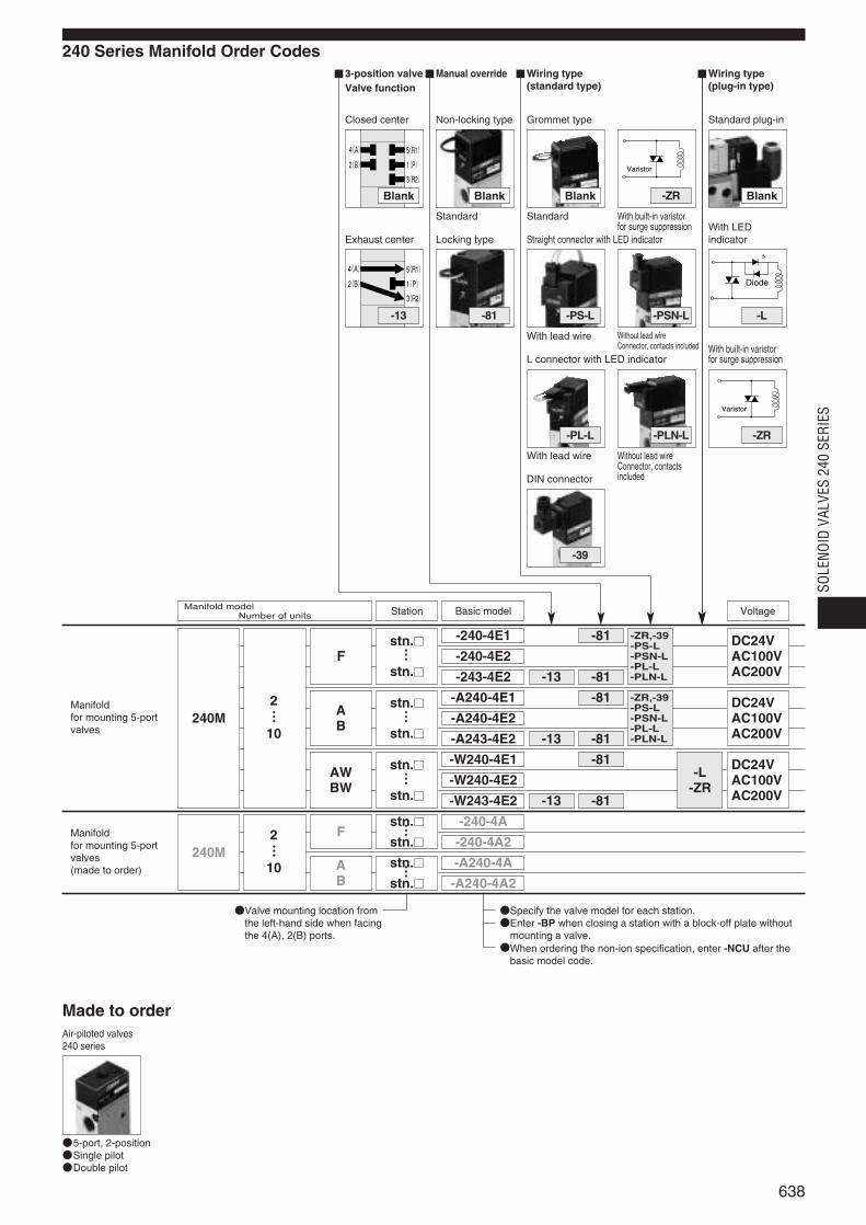
240 Series Manifold Order Codes
stn.
stn.F
AB
AWBW
F
AB
2……10
2……10
240M
240M
……
stn.
stn.……
stn.
stn.……
stn.
stn.……
stn.
stn.……
Valve mounting location fromthe left-hand side when facingthe 4(A), 2(B) ports.
Specify the valve model for each station.Enter -BP when closing a station with a block-off plate without
mounting a valve.When ordering the non-ion specification, enter -NCU after the
basic model code.
-240-4E1
Basic modelManifold modelNumber of units Station Voltage
-ZR,-39-PS-L-PSN-L-PL-L-PLN-L
-ZR,-39-PS-L-PSN-L-PL-L-PLN-L
-81
-81
-81
-81
-81-L
-ZR-81
-13
-13
-13
DC24VAC100VAC200V
DC24VAC100VAC200V
DC24VAC100VAC200V
638
SOLE
NOID
VAL
VES
240
SERI
ES
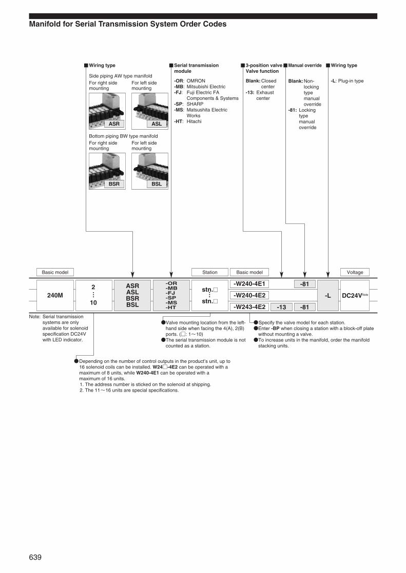
Manifold for Serial Transmission System Order Codes
Side piping AW type manifoldFor right side For left sidemounting mounting
Bottom piping BW type manifoldFor right side For left sidemounting mounting
BSR BSL
ASR ASL
Manual override Wiring type3-position valveValve function
-L: Plug-in typeBlank: Non-lockingtypemanualoverride
-81: Lockingtypemanualoverride
Blank: Closedcenter
-13: Exhaustcenter
Serial transmissionmodule
-OR: OMRON-MB: Mitsubishi Electric-FJ: Fuji Electric FA
Components & Systems-SP: SHARP-MS: Matsushita Electric
Works-HT: Hitachi
Wiring type
-W240-4E1
-W240-4E2
-W243-4E2
Basic modelStationBasic model Voltage
-81
-81-13
-L DC24VNotestn.
stn.
-OR-MB-FJ-SP-MS-HT
ASRASLBSRBSL
2……10
240M ……
Note: Serial transmissionsystems are onlyavailable for solenoidspecification DC24Vwith LED indicator.
Specify the valve model for each station.Enter -BP when closing a station with a block-off plate
without mounting a valve.To increase units in the manifold, order the manifold
stacking units.
Valve mounting location from the left-hand side when facing the 4(A), 2(B)ports. (: 1~10)The serial transmission module is not
counted as a station.
Depending on the number of control outputs in the product’s unit, up to16 solenoid coils can be installed. W24-4E2 can be operated with amaximum of 8 units, while W240-4E1 can be operated with amaximum of 16 units. 1. The address number is sticked on the solenoid at shipping.2. The 11~16 units are special specifications.
639

Single solenoid 2-position double solenoid 3-position double solenoid
Closed center Exhaust center
Symbols
Operating Principles and Major Parts
240-4E1
De-energized Energized
Major Parts and Materials
5(R1)
3(R2)1(P)
4(A)2(B)
5(R1)
3(R2)1(P)2(B)
4(A)
12(S1)
14(S2)
5(R1)
3(R2)1(P)2(B)
4(A)
12(S1)
14(S2)
5(R1)
3(R2)1(P)2(B)
4(A)
12(S1)
14(S2)
Parts Materials
Body Aluminum alloy (treated with chromic acid)
Stem Aluminum alloy (anodized)
Lip sealSynthetic rubber
Flapper
Mounting base Mild steel (zinc plated)
Sub-base Aluminum alloy (anodized)
Plunger Magnetic stainlessColumn steel
PR
5(R1)
3(R2)
1(P)
2(B)
4(A)
Solenoid cover
Column
Shading coil (AC solenoid only)
Molded solenoid
Plunger
Plunger spring
Manual override
Plunger pin
Piston
Pilot valve body
Flapper
Stem
Body
Lip seal
End cover
240-4E2(De-energized condition after energizing solenoid 12(S1))
4(A)
2(B)
5(R1)
3(R2)
1(P)
12(S1)
14(S2)
243-4E2(Both solenoid 12(S1)and 14(S2)are de-energized.)
1(P)
2(B)
4(A)
12(S1)
14(S2)
243-4E2-13(Both solenoid 12(S1)and 14(S2)are de-energized.)
1(P)
2(B)
4(A)
12(S1)
14(S2)
5(R1)
3(R2)
1(P)
2(B)
4(A)
Remark: Materials that generate copperions are not used for the non-ion specification.
640
SOLE
NOID
VAL
VES
240
SERI
ES

Dimensions of Solenoid Valve (mm)
240-4E1
240-4E2
A
B
R1
P
R2
3-Rc1/42
77
2
99
23 35
8
33
103.
2
40 2224
.5
19.6
3617
.525.7
15.5
11.5
11.5
2-φ3.3 2-φ3.3
PR2
PR1
2-Rc1/8
35.5
Manual override
2-M3×0.5 Depth 4Mounting thread
Non-locking type: Standard Locking type: -81
Approximately 300
Counterbore R3 Depth 3Mounting hole
4(A)Port
2(B)Port
5(R1)Port
3(R2)Port
1(P)PortMounting hole
AR1
R2
P
B
33
3649
.7
2-PR
2-Rc1/8
67.7
35
8
19.6
57.9
2-φ3.3
3-Rc1/4
22
99
23
135.
4 40 2256
.7
47.7
2-φ3.3
14(S2)
12(S1)
2(B)Port
5(R1)Port
3(R2)Port
1(P)Port
2-Manual overridesNon-locking type
Approximately 300
Counterbore R3 Depth 3Mounting hole
4(A)Port
Mounting hole
240-4E1
240-4E2
641
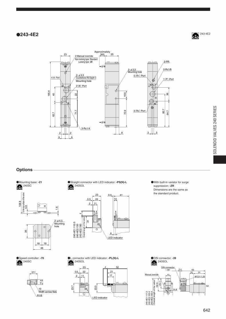
243-4E2
Options
Mounting base: -21 Straight connector with LED indicator: -PS(N)-L With built-in varistor for surgesuppression: -ZRDimensions are the same asthe standard product.
Speed controller: -70 L connector with LED indicator: -PL(N)-L DIN connector: -39
165.
4
3-Rc1/4
2-φ3.3
23
14(S2)
12(S1)
AR1
R2B
4062
.7 71.7
22
2 2
9 9
35
19.6
72.9 82.7
64.7
8
2-PR
2-Rc1/8
P
36
3 3
2-Manual override
2-φ3.3 5(R1)Port
3(R2)Port
1(P)Port
Non-locking type: Standard Locking type: -81
Approximately 300
Counterbore R3 Depth 3Mounting hole
4(A)Port
2(B)Port
Mounting hole
2-φ4.5
18
46
35
108.
8
5.6
1.6
18
B
(To t
he to
p surf
ace o
f the v
alve)
Mounting hole
23
220.5
2 11
0.5 41
10
6
31
R
LED indicator 24
0-4E
1:11
0.5
24
0-4E
2:15
0
243-
4E2:
180
(O
vera
ll le
ngth
of t
he v
alve)
(21)
11.4
R1/8
10Width across flats
23
0.5 22
2 11
23.7
23.5
52
21
17
R
LED indicator
2.4 6310 31
13M12×1.25
(32
.5)
(25
.1)
14.8
φ14.8S2
DIN connector(-39)
Manual override
240-
4E1:
117.
224
0-4E
2:16
3.4
243-
4E2:
193.
4(
Ove
rall
leng
th o
f the
val
ve)
243-4E2
240SC
240SC 240SOL 240SOL
240SOL
642
SOLE
NOID
VAL
VES
240
SERI
ES

Dimensions of Solenoid Valve (mm)
A240-4E1-25A240-4E1-27
A240-4E2-25A240-4E2-27
〈Viewed from A〉-27: Bottom port
PR
5(R1)
4(A)
2(B)
3(R2)
1(P)
21
43 82.5
38.5
27.5
35
43
21
A
23
34 4.52-φ4.5
119
55
103.
2
68.5
5.5
58.5
40
30
104.5
2119
.5
10
Rc1/8PR
5-Rc1/4
Manual overrideNon-locking type: Standard Locking type: -81
Approximately300
Mounting hole
PR
5(R1)
4(A)
2(B)
3(R2)
1(P)
21
34 4.5
23
43
38.5
35
A
43
27.5
21
82.5
9 11
10
55
2119
.5
135.
4 68.5
58.5
4010
30
4.5
37.7
Rc1/8
5-Rc1/4
2-φ4.5
PR
12(S1)
14(S2)
Non-locking type
Approximately300
Mounting hole
2-Manual overrides
M5×0.8
5-Rc1/4
PR
25
34.5
10.5
55 4010
23
30
18.5
R
A
B
P
R
PR
5(R1)Port
1(P)Port
4(A)Port
2(B)Port
3(R2)Port
A240-4E1
A240-4E2
643
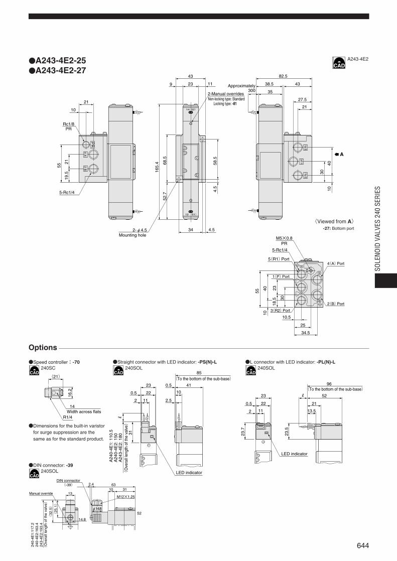
A243-4E2-25A243-4E2-27
〈Viewed from A〉-27: Bottom port
Options
DIN connector: -39
Straight connector with LED indicator: -PS(N)-L L connector with LED indicator: -PL(N)-LSpeed controller:-70
Dimensions for the built-in varistorfor surge suppression are thesame as for the standard product.
Width across flats14
(21)
16.2
R1/4
2.4 6310 31
13M12×1.25
(32
.5)
(25
.1)
14.8
φ14.8S2
DIN connector(-39)
Manual override
240-
4E1:
117.
224
0-4E
2:16
3.4
243-
4E2:
193.
4(
Ove
rall
leng
th o
f the
val
ve)
(O
vera
ll le
ngth
of t
he v
alve)
A24
0-4E
1: 1
10.5
A24
0-4E
2: 1
50A
243-
4E2:
180
LED indicator
(To the bottom of the sub-base)23
220.5
2 11
R
31
85
410.5
2.5
1023
22
11
0.5
2
23.7
96
52
21
23.5
13.5
R
LED indicator
(To the bottom of the sub-base)
PR
4(A)
2(B)
5(R1)
3(R2)
1(P)
12(S1)
14(S2)
21
4.534
23
43
38.5
35
A
43
27.5
21
82.5
9 11
10
55
2119
.5 165.
4 68.5
58.5
4010
30
4.5
52.7
Rc1/8
5-Rc1/4
2-φ4.5
PR
2-Manual overridesNon-locking type: Standard Locking type: -81
Approximately300
Mounting holeM5×0.8
5-Rc1/4
PR
25
34.5
10.5
55 4010
23
30
18.5
R
A
B
P
R
PR
5(R1)Port
1(P)Port
4(A)Port
2(B)Port
3(R2)Port
A243-4E2
240SC 240SOL 240SOL
240SOL
644
SOLE
NOID
VAL
VES
240
SERI
ES
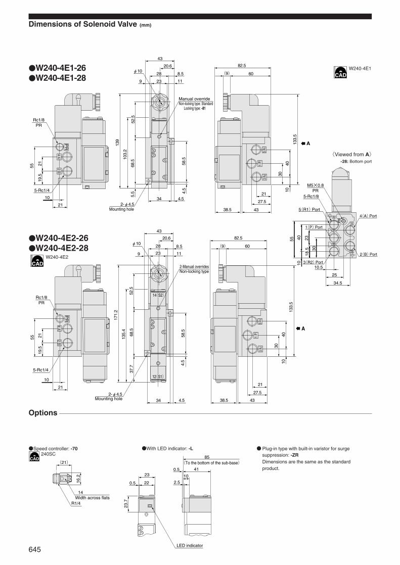
Dimensions of Solenoid Valve (mm)
W240-4E1-26W240-4E1-28
W240-4E2-26W240-4E2-28
〈Viewed from A〉-28: Bottom port
M5×0.8PR
5-Rc1/8
55 40 2318
.5 30
10
10.5
25
34.5
A
B
R
P
R
PR
5(R1)Port
1(P)Port
3(R2)Port
4(A)Port
2(B)Port
Rc1/8PR
19.5
2155
PR
5-Rc1/4
10
21
43
20.6
8.5
11
28
239
φ10
171.
2
135.
4
68.5
52.5
37.7
2-φ4.534 4.5
4.5
58.5
82.5
60(9)
133.
5
40
30
10
38.5
21
27.5
43
12(S1)
14(S2)
A
5(R1)
3(R2)
1(P)
4(A)
2(B)
2-Manual overridesNon-locking type
Mounting hole
Options
With LED indicator: -LSpeed controller: -70 Plug-in type with built-in varistor for surgesuppression: -ZRDimensions are the same as the standardproduct.
A
Mounting hole
Manual overrideNon-locking type: Standard Locking type: -81
Rc1/8PR
19.5
2155
PR
5-Rc1/4
10
21
43
20.6
8.5
11
28
239
φ10
139
103.
2
68.5
52.5
5.5
2-φ4.534 4.5
4.5
58.5
82.5
60(9)
133.
5
40
30
10
38.5
21
27.5
43
4(A)
2(B)
5(R1)
3(R2)
1(P)
Width across flats14
(21)
16.2
R1/4
23
220.5
23.7
85
0.5
2.5
41
10
LED indicator
(To the bottom of the sub-base)
W240-4E1
W240-4E2
240SC
645

Dimensions of Manifold (mm)
240MF
Options
Built-in varistor for surge suppression: -ZRDimensions are the same as the standardproduct.
DIN connector:-39
64
35 28
19
11
4011
162021
52 62
165.
4
31
106-Rc1/4
23
L
P5
4-φ4.5
5
24242424
2323
2 2
12.512.5
2224
.5
4.5
35.5
51.736
.7
67.7
98.7
Rc1/4
(-BP)243-4E2240-4E2
stn.1 stn.2 stn.3 stn.4 stn.5
240-4E1
A
B
A
B
A
B
A
B
14(S2)
14(S2)
12(S1)
12(S1)
5(R1)
3(R2)
1(P)
(with 3 plugs)
4(A)Port
2(B)Port
Block-off plate
Manual overrideNon-locking type: Standard Locking type: -81
Approximately 300
Mounting hole
Model
240M2F
240M3F
240M4F
240M5F
240M6F
240M7F
240M8F
240M9F
240M10F
L P
72
96
120
144
168
192
216
240
264
62
86
110
134
158
182
206
230
254
Unit dimensions
Straight connector with LED indicator: -PS(N)-L L connector with LED indicator: -PL(N)-L
81
52
21
17
R23
220.5
2 11
23.7
23.5
LED indicator
(To the bottom of the manifold)
70
41
10
0.523
220.5
2 11
6
R
31(
Ove
rall l
engt
h of
the
valve)
240-
4E1:
110.
524
0-4E
2:15
024
3-4E
2:18
0
LED indicator
(To the bottom of the manifold)
2.4 6310 31
13M12×1.25
(32
.5)
(25
.1)
14.8
φ14.8S2
DIN connector(-39)
Manual override
240-
4E1:
117.
224
0-4E
2:16
3.4
243-
4E2:
193.
4(
Ove
rall
leng
th o
f the
val
ve)
240MF
240SOL 240SOL
240SOL
646
SOLE
NOID
VAL
VES
240
SERI
ES

Dimensions of Manifold (mm)
240MA240MB
Options
With built-in varistor forsurge suppression: -ZRDimensions are the sameas the standard product.
DIN connector: -39
23
22
11
0.5
2
31
R
2.5
0.5 41
10
89.5
A24
0-4E
1:11
0.5
A24
0-4E
2:15
0A
243-
4E2:
180
(O
vera
ll le
ngth
of t
he v
alve)
LED indicator
(To the bottom of the manifold)
2.4 6310 31
13M12×1.25
(32
.5)
(25
.1)
14.8
φ14.8S2
DIN connector(-39)
Manual override
240-
4E1:
117.
224
0-4E
2:16
3.4
243-
4E2:
193.
4(
Ove
rall
leng
th o
f the
val
ve)
Model
240M2A, 240M2B
240M3A, 240M3B
240M4A, 240M4B
240M5A, 240M5B
240M6A, 240M6B
240M7A, 240M7B
240M8A, 240M8B
240M9A, 240M9B
240M10A, 240M10B
L P
117
145
173
201
229
257
285
313
341
107
135
163
191
219
247
275
303
331
Unit dimensions
Straight connector with LED indicator: -PS(N)-L L connector with LED indicator: -PL(N)-L
23
22
11
0.5
2
R
13.5
52
21
100.5
23.7
23.5
LED indicator
(To the bottom of the manifold)
per each station
〈Viewed from A〉240MB: Bottom port5(R1)Port4(A)Port
3(R2)Port
1(P)Port
2(B)Port
64 79
165.
4
7.5
53
44.2
42.2
4716
2230
413
3
L
P5
4-R2.5
5
44.5282844.5
23 332333
12.512.5
103.
25
37.5
11.5 5
15
5
29.2
7927
.2
87
38.5
35
47.5
37
32
3126
.541.5
PR
15.5
176-Rc1/4
2-Rc1/4
1
4
5-Rc1/8
2-Rc1/8PR
R1
AR
2
PB
R1
AR
2
PB
R1
AR
2
PB
R1
AR
2
PB
R1
AR
2
PB
30.5 28
146.5 14
28
7.5
30.5
(-BP)A243-4E2A240-4E2
stn.1 stn.2 stn.3 stn.4 stn.5
A240-4E1
A
B
A
B
A
B
A
B
A
B
A5(R1)
3(R2)1(
P)
Manual overrideNon-locking type: Standard Locking type: -81
Approximately300
Mounting hole
per each station
4(A)Port2(B)Port
Block-off plate
240MA
240SOL 240SOL
240SOL
647
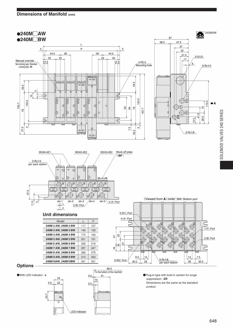
L
P5 5
87
38.5 47.5
37
32
21.5
17
6
110.
5
31
41.5
15.5 26
.5
2-G1/2
6-Rc1/4
2-Rc1/8
W243-4E2
1
4
W240-4E2W240-4E1
2-Rc1/4
5-Rc1/8
(-BP )
4-R2.5
44.5 44.528 28
33 3323 23
12.5
152.
7
37.5
11.5 5
79
53 647.
5
47 22
41
16
44.2
125.
53
167.
77942
.2
15
5
29.2
103.
25
27.2
12.5
30.530.5 2828
1414 7.56.5
30
stn.1 stn.2 stn.3 stn.4 stn.5
B
A
B
A
B
A
B
A
B
A
A
R1
PB
R2
A
R1
PB
R2
A
R1
PB
R2
A
R1
PB
R2
A
R1
PB
R2
PR
14(S2)
12(S1)
12(S1)
14(S2)
A5(R1)
3(R2)
1(P)
Manual overrideNon-locking type: Standard Locking type: -81 Mounting hole
per each station
2(B)Port4(A)Port
Block-off plate
per each station
〈Viewed from A〉240MBW: Bottom port
5(R1)Port
4(A)Port
3(R2)Port
1(P)Port
2(B)Port
Dimensions of Manifold (mm)
240MAW240MBW
Options
With LED indicator: -L Plug-in type with built-in varistor for surgesuppression: -ZRDimensions are the same as the standardproduct.
23
23.7
89.5
410.5
2.5
10220.5
LED indicator
(To the bottom of the manifold)
Model
240M 2 AW, 240M 2 BW
240M 3 AW, 240M 3 BW
240M 4 AW, 240M 4 BW
240M 5 AW, 240M 5 BW
240M 6 AW, 240M 6 BW
240M 7 AW, 240M 7 BW
240M 8 AW, 240M 8 BW
240M 9 AW, 240M 9 BW
240M10AW, 240M10BW
L P
117
145
173
201
229
257
285
313
341
107
135
163
191
219
247
275
303
331
Unit dimensions
240MAW
648
SOLE
NOID
VAL
VES
240
SERI
ES
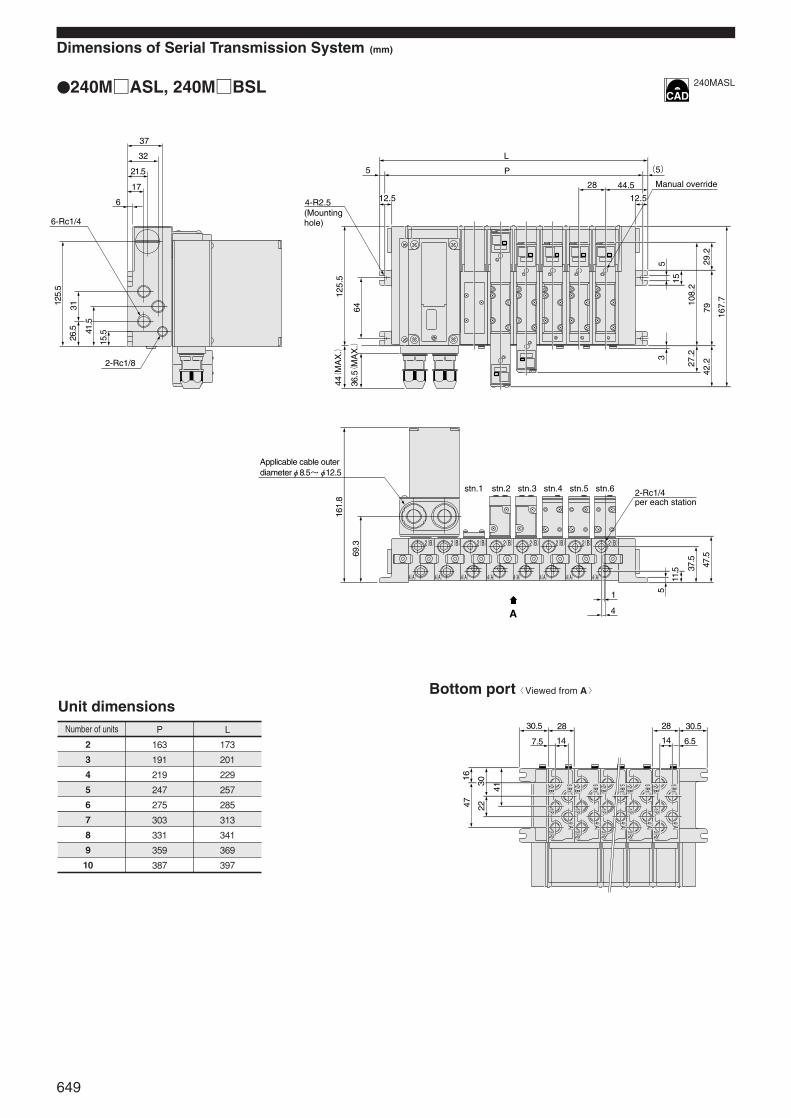
Dimensions of Serial Transmission System (mm)
240MASL, 240MBSL
Bottom port〈Viewed from A〉
Unit dimensionsNumber of units
2
3
4
5
6
7
8
9
10
P
163
191
219
247
275
303
331
359
387
L
173
201
229
257
285
313
341
369
397
37
32
21.5
17
6
6-Rc1/4
2-Rc1/8
125.
5
26.5 41
.5
15.5
31
5
L
P
12.5
28 44.5
(5)
12.5
125.
5
5
167.
7
7942
.229
.2
15
108.
2
3
27.2
64
4-R2.5
44(
MA
X.)
36.5(
MA
X.)
161.
8
69.3
1
4
5
11.5 37
.5
47.5
A
2(B) 2(B) 2(B) 2(B) 2(B) 2(B) 2(B) 2(B)
4(A) 4(A) 4(A) 4(A) 4(A) 4(A) 4(A) 4(A)
stn.1 stn.2 stn.3 stn.4 stn.5 stn.6
30.5 30.528 28
7.5
4716
3022
41
6.514 14
3(R2)
3(R2)
3(R2)
3(R2)
3(R2)
2(B)
2(B)
2(B)
2(B)
2(B)
1(P)
1(P)
1(P)
1(P)
1(P)
4(A)
4(A)
4(A)
4(A)
4(A)
5(R1)
5(R1)
5(R1)
5(R1)
5(R1)
Applicable cable outer diameterφ8.5~φ12.5
2-Rc1/4per each station
Manual override
(Mounting hole)
240MASL
649
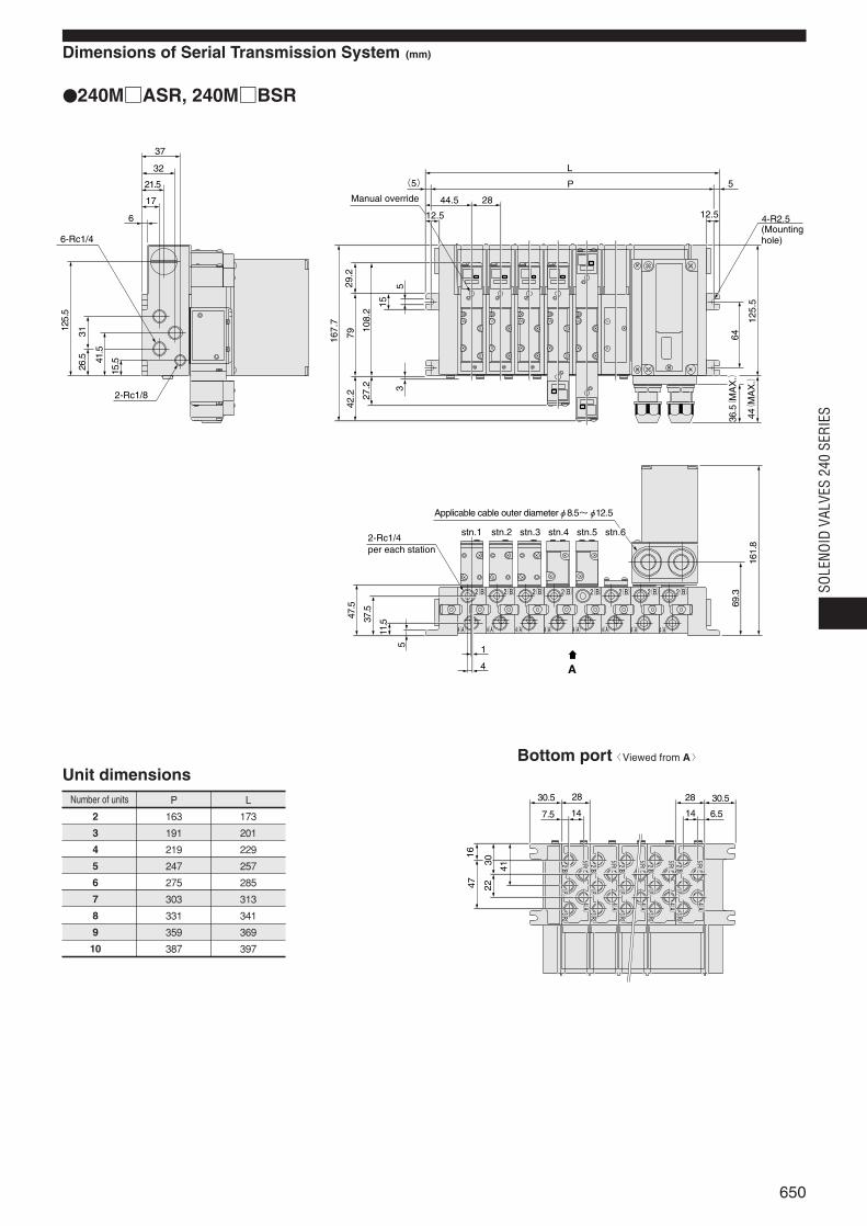
Unit dimensionsNumber of units
2
3
4
5
6
7
8
9
10
P
163
191
219
247
275
303
331
359
387
L
173
201
229
257
285
313
341
369
397
Dimensions of Serial Transmission System (mm)
240MASR, 240MBSR
Bottom port〈Viewed from A〉
37
32
21.5
17
6
6-Rc1/4
2-Rc1/8
125.
5
26.5 41
.5
15.5
31
5
L
P
12.5
2844.5
(5)
12.5
125.
5
5
167.
7
7942
.229
.2
15
108.
2
3
27.2
64
4-R2.5
44(
MA
X.)
36.5(
MA
X.)
161.
8
69.3
1
4
5
11.537
.5
47.5
A
30.530.5 2828
6.5
4716
3022
41
7.5 1414
stn.1 stn.2 stn.3 stn.4 stn.5 stn.6
3(R2)
3(R2)
3(R2)
3(R2)
3(R2)
2(B)
2(B)
2(B)
2(B)
2(B)
2(B) 2(B) 2(B) 2(B) 2(B) 2(B) 2(B) 2(B)
4(A) 4(A) 4(A) 4(A) 4(A) 4(A) 4(A) 4(A)
4(A)
4(A)
4(A)
4(A)
4(A)
5(R1)
5(R1)
5(R1)
5(R1)
5(R1)
1(P)
1(P)
1(P)
1(P)
1(P)
2-Rc1/4per each station
Manual override
(Mounting hole)
Applicable cable outer diameterφ8.5~φ12.5
650
SOLE
NOID
VAL
VES
240
SERI
ES
240MF240MA240MB
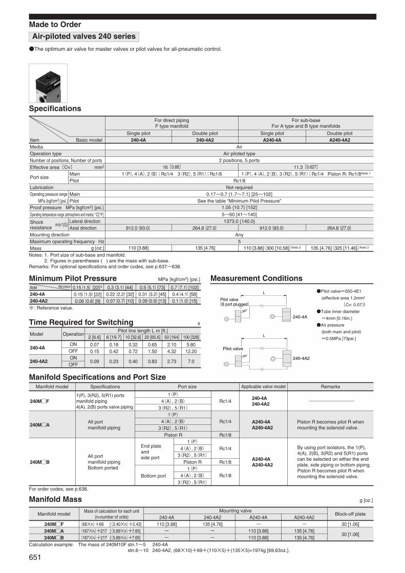
Air-piloted valves 240 series
Main pressureModel
240-4A240-4A2
Proof pressure MPa kgf/cm2 [psi.]
Effective area〔Cv〕 mm2
Made to Order
The optimum air valve for master valves or pilot valves for all-pneumatic control.
MediaOperation type
1(P), 3(R2), 5(R1) portsmanifold piping4(A), 2(B) ports valve piping
240MF
0.15{1.5}[22]※
0.15{1.5}[22]0.06{0.6}[9]
240MA
240MB
Mounting directionMaximum operating frequency HzMass g [oz.]
Operating temperature range (atmosphere and media) °C[°F]
Operating pressure rangeMPa kgf/cm2 [psi.]
MainPilot
※: Reference value.
Specifications
Item Basic modelAir
Air piloted type2 positions, 5 ports
Rc1/8
16〔0.88〕1(P), 4(A), 2(B):Rc1/4 3(R2), 5(R1):Rc1/8
11.3〔0.627〕1(P), 4(A), 2(B), 3(R2), 5(R1):Rc1/4 Piston R: Rc1/8Note 1
Number of positions, Number of ports
Not required0.17~0.7 1.7~7.1 [25~102]
See the table “Minimum Pilot Pressure”1.05 10.7 [152]
5~60 [41~140]1373.0 140.0
Any5
Port size
m/s2G
MainPilot
Lateral directionAxial direction
Lubrication
For direct pipingF type manifold
For sub-baseFor A type and B type manifolds
Single pilot
912.0{93.0} 264.8{27.0} 912.0{93.0} 264.8{27.0}
110 [3.88] 135 [4.76] 110 [3.88](300 [10.58])Note 2 135 [4.76](325 [11.46])Note 2
Double pilot Single pilot Double pilot240-4A 240-4A2 A240-4A A240-4A2
Manifold Specifications and Port SizeManifold model Specifications
All portmanifold piping
All portmanifold pipingBottom ported
End plateandside port
Bottom port
Port size
1(P)4(A), 2(B)3(R2), 5(R1)1(P)
4(A), 2(B)3(R2), 5(R1)
Piston R1(P)
4(A), 2(B)3(R2), 5(R1)
Piston R1(P)
4(A), 2(B)3(R2), 5(R1)
Rc1/4
Rc1/4
Rc1/8
Rc1/4
Rc1/8
Rc1/8
Applicable valve model Remarks
Piston R becomes pilot R when mounting the solenoid valve.
By using port isolators, the 1(P),4(A), 2(B), 3(R2) and 5(R1) portscan be selected on either the endplate, side piping or bottom piping.Piston R becomes pilot R whenmounting the solenoid valve.
For order codes, see p.638.
0.3{3.1}[44]0.22{2.2}[32]0.07{0.7}[10]
0.5{5.1}[73]0.31{3.2}[45]0.09{0.9}[13]
0.7{7.1}[102]0.4{4.1}[58]0.1{1.0}[15]
Minimum Pilot Pressure MPa kgf/cm2 [psi.] Measurement Conditions
240-4A
240-4A2
Model Operation
ONOFFONOFF
Pilot line length L m [ft.]
0.070.15
0.180.42
0.320.72
0.651.50
2.104.32
5.8012.20
2 [6.6] 6 [19.7] 10 [32.8] 20 [65.6] 50 [164] 100 [328]
0.09 0.23 0.40 0.83 2.73 7.0
Time Required for Switching s
240-4A240-4A2
A240-4AA240-4A2
A240-4AA240-4A2
Manifold Mass g [oz.]
Manifold modelMass of calculation for each unit
(n=number of units)
(68×n)+69 [(2.40×n)+2.43](167×n)+217 [(5.89×n)+7.65](167×n)+217 [(5.89×n)+7.65]
110 [3.88]--
135 [4.76]--
-110 [3.88]110 [3.88]
-135 [4.76]135 [4.76]
30 [1.06]
30 [1.06]
Mounting valve240-4A 240-4A2 A240-4A A240-4A2
Block-off plate
Calculation example: The mass of 240M10F stn.1~51 240-4AThe mass of 240M10F stn.6~10 240-4A2, (68×10)+69+(110×5)+(135×5)=1974g [69.63oz.].
Notes: 1. Port size of sub-base and manifold.2. Figures in parentheses ( ) are the mass with sub-base.
Remarks: For optional specifications and order codes, see p.637~638.
Pilot valve=050-4E1
(effective area 1.2mm2
〔Cv: 0.07〕)
Tube inner diameter
=4mm [0.16in.]
Air pressure
(both main and pilot)
=0.5MPa [73psi.]
L
L
240-4A
240-4A2
Pilot valve
Pilot valve
(B port plugged)
651
Shock resistance
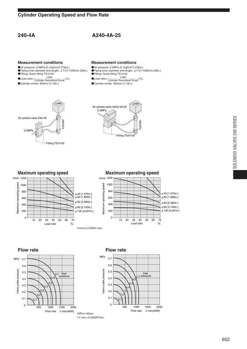
Cylinder Operating Speed and Flow Rate
240-4A A240-4A-25
0.5MPa
Fitting TS10-02
Air-piloted valve A240-4A-25Load
Cyl
inde
r
1200
1000
800
600
400
200
010 20 30 40 50 60 70
%
φ40 [1.575in.]φ50 [1.969in.]
φ63 [2.480in.]
φ80 [3.150in.]
φ100 [3.937in.]
mm/s
0.70.6
0.50.4
0.3
0.2
0.1
R/min(ANR)
0.7
0.6
0.5
0.4
0.3
0.2
0.1
0
MPa
500 1000 1500 2000
Val
ve o
utle
t pre
ssur
e
Flow rate
Load ratio
Max
imum
ope
ratin
g sp
eed
Inlet pressure 0.7
0.6
0.5
0.40.3
0.2
0.1
R/min(ANR)
0.7
0.6
0.5
0.4
0.3
0.2
0.1
0
MPa
500 1000 1500 2000
1200
1000
800
600
400
200
010 20 30 40 50 60 70
%
φ40 [1.575in.]φ50 [1.969in.]
φ63 [2.480in.]
φ80 [3.150in.]φ100 [3.937in.]
mm/s
Val
ve o
utle
t pre
ssur
e
Flow rate
Load ratio
Max
imum
ope
ratin
g sp
eed
Inlet pressure
652
SOLE
NOID
VAL
VES
240
SERI
ES
Measurement conditionsAir pressure: 0.5MPa 5.1kgf/cm2 [73psi.]Piping inner diameter and length: φ7.5×1000mm [39in.]Fitting: Quick fitting TS10-02
LoadLoad ratio=
Cylinder theoretical thrust(%)
Cylinder stroke: 300mm [11.8in.]
Measurement conditionsAir pressure: 0.5MPa 5.1kgf/cm2 [73psi.]Piping inner diameter and length: φ7.5×1000mm [39in.]Fitting: Quick fitting TS10-02
LoadLoad ratio=
Cylinder theoretical thrust(%)
Cylinder stroke: 300mm [11.8in.]
Maximum operating speed Maximum operating speed
Flow rate Flow rate
1mm/s=0.0394in./sec.
1MPa=145psi.
1R/min.=0.0353ft3/min.
0.5MPa
Fitting TS10-02
Air-piloted valve 240-4A
Load
Cyl
inde
r
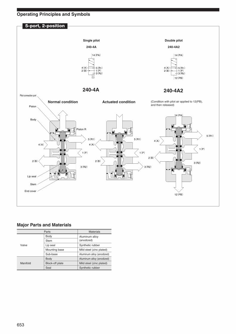
Operating Principles and Symbols
5-port, 2-position
Single pilot
240-4A
Double pilot
240-4A2
240-4A 240-4A2
Normal condition Actuated condition
Parts
Valve
Manifold
Materials
Body
Stem
Lip seal
Mounting base
Sub-base
Body
Block-off plate
Seal
Aluminum alloy (anodized)
Synthetic rubber
Mild steel (zinc plated)
Aluminum alloy (anodized)
Aluminum alloy (anodized)
Mild steel (zinc plated)
Synthetic rubber
Major Parts and Materials
5(R1)
3(R2)1(P)
4(A)2(B)
14(PA)
5(R1)
3(R2)1(P)
4(A)2(B)
14(PA)
12(PB)
14(PA)
12(PB)
4(A)
2(B)
5(R1)
1(P)
3(R2)
4(A)
2(B)
4(A)
2(B)
5(R1)
1(P)
3(R2)
5(R1)
1(P)
3(R2)
Piston
Piston R
Stem
Body
Lip seal
End cover
Pilot connection port
653
(Condition with pilot air applied to 12(PB),and then released)

Dimensions of Air-piloted Valves (mm)
240-4A
240-4A2
Options
2-Rc1/8
Rc1/8
3-Rc1/4
23
2
77
2
99
35
8
2-φ3.3
3
3617
.5
3
35.5
25.7
2224
.5
11.5
11.5
4079.5
15.5
19.6
4(A)
2(B)
5(R1)
1(P)
3(R2)
2-Piston R
2-φ3.3 Counterbore R3 Depth 3Mounting hole
2-M3×0.5 Depth 4Mounting thread
Pilot connection port
Mounting hole
2-Rc1/8
3-Rc1/4
23
22
99
2233
4088
24 12(PB)
14(PA)
35
8
2-φ3.3
34.2
19.6
2-Rc1/8
3
3626
3
44
4(A)
2(B)
5(R1)
1(P)
3(R2)
2-Piston R
2-φ3.3 Counterbore R3 Depth 3Mounting hole
Pilot connection port
Mounting hole
Mounting base: -21 Speed controller: -70
2-φ4.5
18
46
35
108.
8
5.6
1.6
18
B
(To t
he to
p surf
ace o
f the v
alve)
Mounting hole
10
(21)
11.4
R1/8Width across flats
654
SOLE
NOID
VAL
VES
240
SERI
ES
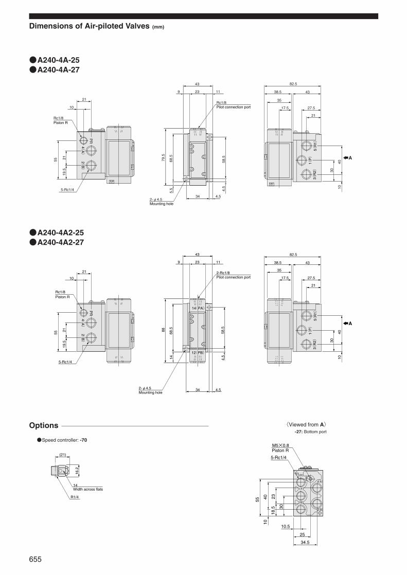
Dimensions of Air-piloted Valves (mm)
A240-4A-25A240-4A-27
Options
Speed controller: -70
A240-4A2-25A240-4A2-27
21
40
3(R
2)
1(P)
5(R
1)
10
30
27.5
43
82.5
38.5
35
17.5
43
23
34 4.5
4.5
58.5
79.5
68.5
5.5
9 11
Rc1/8
2-φ4.5
A
5-Rc1/4
21
10
Rc1/8
55
19.5
21
PR
4(A)
2(B)
Piston R
Pilot connection port
Mounting hole
21
40
3(R
2)1(
P)
5(R
1)
10
30
27.5
43
82.5
38.5
35
17.5
43
23
34 4.5
4.5
58.5
88
68.5
14
9 11
2-Rc1/8
2-φ4.5
A
5-Rc1/4
21
10
Rc1/8
55
19.5
21
PR
4(A)
2(B)
14(PA)
12(PB)
Piston R
Pilot connection port
Mounting hole
(21)
16.2
14
R1/4
Width across flats
Piston RM5×0.8
5-Rc1/4
25
34.5
10.5
55 4010
23
30
18.5
5(R1)
4(A)
2(B)
1(P)
3(R2)
PR
655
〈Viewed from A〉-27: Bottom port

Handling Instructions and Precautions
Solenoid
AC100V, AC200V
Standard solenoid
Solenoid with LED indicator (Surge suppression)Order code: -PS-L
-PL-L
DC24V
Standard solenoid (Surge suppression)
Solenoid with LED indicator (Surge suppression)Order code: -PS-L
-PL-L
Plug connector Manual override
Solenoid (Surgesuppression)Order code: -ZR
※Illustration shows the 110 series.
C
Protruded section
Pin
Connector housing
Lever
Connector
Indication of polarity(DC)
Contact
Connector assembly
PUSH
TURN
PUSH
Hook Exposed wire crimping section
Insulation crimp tabInsulation(Maximum outer diameterφ1.7)
Lead wireEquivalent to AWG22~26
Exposed wire 4mm
Contact
Varistor
Solenoid
Lead wire AC100V: YellowAC200V: White
Color of LED indicator AC100V: YellowAC200V: Green
LED indicator(Light Emitting Diode)
Diode
(+)
(-)
Short circuit protection diode
Flywheel diode
Solenoid
Lead wire: Black
Lead wire: Red
(+)
(-)LED indicator: RedLead wire: Black
Lead wire: Red
LED indicator(Light Emitting Diode)
656
SOLE
NOID
VAL
VES
240
SERI
ES
Internal circuit Attaching and removing plug connector
Use fingers to insert the connector into thepin, push it in until the lever claw latchesonto the protruded section of the connectorhousing, and complete the connection.To remove the connector, squeeze the leveralong with the connector, lift the lever clawup from the protruded section of theconnector housing, and pull it out.
Crimping of connecting lead wire and contact
To crimp lead wires into contacts, strip off4mm [0.16in.] of the insulation from the tipof the lead wire, insert it into the contact,and crimp it. Be sure to avoid catching theinsulation on the exposed wire crimpingsection.
Attaching and removing contact and connector
Insert the contact with lead wire into a plugconnector hole until the contact hooklatches on the connector and is secured tothe plug connector. Confirm that the leadwire cannot be easily pulled out.To remove it, insert a tool with a fine tip(such as a small screwdriver) into therectangular hole on the side of the plugconnector to push up on the hook, and thenpull out the lead wire.
Cautions: 1. Do not pull hard on the lead wire. Itcould result in defective contacts,breaking wires, etc.
2. If the pin is bent, use a smallscrewdriver, etc. to gently straightenout the pin, and then complete theconnection to the plug connector.
Cautions: 1. Do not pull hard on the lead wire.2. Always use a dedicated tool for
crimping of connecting lead wireand contact.Contact: Model 702062-2MManufactured by Sumiko Tech, Inc.Crimping tool: Model F1-702062Manufactured by Sumiko Tech, Inc.
Cautions: 1. The 240 series valves are pilot typesolenoid valves. As a result, themanual override cannot switch themain valve without air supplied fromthe 1(P) port.
2. Always release the lock of the lock-ing type manual overrides beforecommencing normal operation.
3. Do not attempt to operate themanual override with a pin or otherobject having an extremely fine tip.It could damage the manualoverride button.
4. Do not turn the adjusting knobmore than needed. It could result indefective operation.
Non-locking type
To operate the manual override, press it allthe way down. For single solenoid, the valveworks the same as when in the energizedstate as long as the manual override ispushed down, and returns to the normalposition upon release.For the double solenoid, pressing the manualoverride on the 12(S1) side switches the12(S1) to enter the energized position, and theunit remains in that state even after themanual override is released. To return it to thenormal position, operate the manual overrideon the 14(S2) side. This is the same for thesolenoids 14(S2).
Locking type
To lock the manual override, use a smallscrewdriver to push down on the manualoverride all the way down and turn it 45degrees. Either turning direction at this timeis acceptable.When locked, turning the manual overridefrom the locking position releases a springon the manual override, returns it to itsnormal position, and releases the lock.When the manual override is not turned, thistype acts just like the non-locking type.
※Illustration shows the 110 series.
※Illustration shows the 240 series.

Manifold
q w
e
r
t y u
i o 10
240MA(W)240MB(W)
End plate B Port isolator Illustration shows 240MAW.
End plate A
657
PipingThe 1(P) port, 3(R2) port, 5(R1) port and PRport are on both ends of the manifold, andpiping direction can be selected depending onthe mounting location. At shipping, the portson one side are plugged. Remove the plugsand then use sealing tape or another sealingagent to tighten in place.
Cautions: 1. For the 1(P) port piping, use a sizethat matches the manifold’s pipingconnection port. Insufficient flow rateor pressure could result in defectivevalve operation or in insufficientactuator output.
2. When installing piping or mufflers tothe 3(R2) and 5(R1) ports, ensurethere wil l be minimum exhaustresistance. On rare occasions,exhaust from valves can interferencewith other valves and actuators.
3. When a multiple number of valvesoperate simultaneously on a multi-unit manifold, or when the manifoldwith valves is used at high frequency,supply air from the 1(P) ports on bothends, and exhaust air from the 3(R2),5(R1) ports on both ends.
4. In bottom ported manifolds (B typeand BW type), use of the bottom1(P), 3(R2) and 5(R1) ports canprevent f low rate or pressureshortages, or exhaust interference.
Stacking unit orderIf stacking part is required due to the addition or replacement of manifold units, use the following order codes to place orders.
No. Parts Order codes Parts lists (quantities)
— Stacking unit for 240MB CR017
B type stacking unit (1): q joints (2), w joint mounting bolts (2), evalve mounting screws (3), r gasket (1), t gasket (1), y O-rings (3), u O-ring (1), Rc1/8 plugs (5), Rc1/4 plugs (2)
— Stacking unit for 240MA
CR016A type stacking unit (1): q joints (2), w joint mounting bolts (2), evalve mounting screws (3), r gasket (1), t gasket (1), y O-rings (3)
— Stacking unit for 240MBW
CR019
BW type stacking unit (1): q joints (2), w joint mounting bolts (2), evalve mounting screws (3), r gasket (1), t gasket (1), y O-rings(3), u O-ring (1), i terminal block (1), o terminal cover (1), !0 connection cover (1), Rc1/8 plugs (5), Rc1/4 plugs (2)
i Terminal block CR020
— Stacking unit for 240MAW
CR018
AW type stacking unit (1): q joints (2), w joint mounting bolts (2), evalve mounting screws (3), r gasket (1), t gasket (1), y O-rings (3), i terminal block (1), o terminal cover (1), !0 connection cover (1)
Handling Instructions and Precautions
Plug-in
Socket
SocketPlug
Plug
No.1 terminal (-)
No. 2 terminal (-)
No.1 terminal (+)No. 2 terminal (+)
2
1
3+_
Solenoid terminal location
Cable
Cable gland
Cable gasketWasher
Cover mounting screw
Gasket
GasketTerminal cover
Lead wire
Lead wire
Terminal body
Terminal body
Pliers
JIS C3306VCTF Electric conductor 0.75mm2 Finished outside 6.6(2 leads) 7.0(3 leads)
Contact
Lead wire stopper
DIN connector
658
SOLE
NOID
VAL
VES
240
SERI
ES
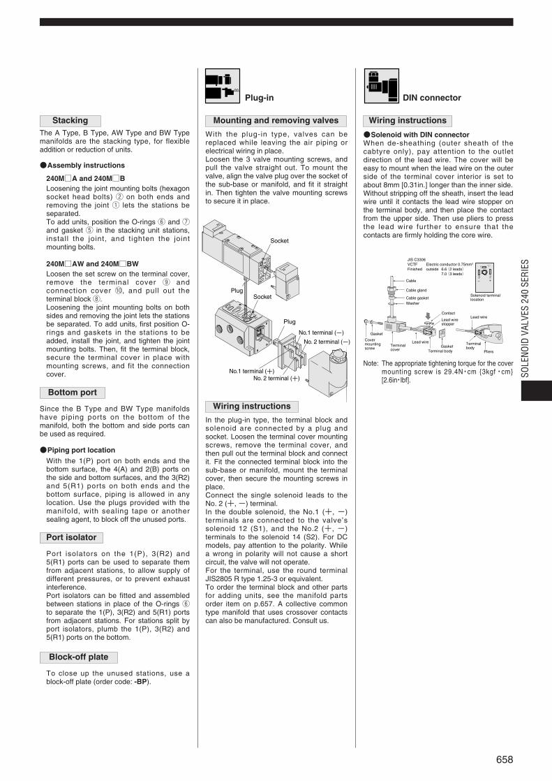
Stacking Mounting and removing valves
With the plug-in type, valves can bereplaced while leaving the air piping orelectrical wiring in place.Loosen the 3 valve mounting screws, andpull the valve straight out. To mount thevalve, align the valve plug over the socket ofthe sub-base or manifold, and fit it straightin. Then tighten the valve mounting screwsto secure it in place.
Wiring instructions
In the plug-in type, the terminal block andsolenoid are connected by a plug andsocket. Loosen the terminal cover mountingscrews, remove the terminal cover, andthen pull out the terminal block and connectit. Fit the connected terminal block into thesub-base or manifold, mount the terminalcover, then secure the mounting screws inplace. Connect the single solenoid leads to the No. 2 (+, -) terminal. In the double solenoid, the No.1 (+, -)terminals are connected to the valve ’ssolenoid 12 (S1), and the No.2 (+, -)terminals to the solenoid 14 (S2). For DCmodels, pay attention to the polarity. Whilea wrong in polarity will not cause a shortcircuit, the valve will not operate.For the terminal, use the round terminalJIS2805 R type 1.25-3 or equivalent.To order the terminal block and other partsfor adding units, see the manifold partsorder item on p.657. A collective commontype manifold that uses crossover contactscan also be manufactured. Consult us.
The A Type, B Type, AW Type and BW Typemanifolds are the stacking type, for flexibleaddition or reduction of units.
Assembly instructions
Loosening the joint mounting bolts (hexagonsocket head bolts) w on both ends andremoving the joint q lets the stations beseparated.To add units, position the O-rings y and uand gasket t in the stacking unit stations,install the joint, and tighten the jointmounting bolts.
240MA and 240MB
Loosen the set screw on the terminal cover,remove the terminal cover o andconnection cover !0, and pull out theterminal block i.Loosening the joint mounting bolts on bothsides and removing the joint lets the stationsbe separated. To add units, first position O-rings and gaskets in the stations to beadded, install the joint, and tighten the jointmounting bolts. Then, fit the terminal block,secure the terminal cover in place withmounting screws, and fit the connectioncover.
240MAW and 240MBW
Bottom port
Since the B Type and BW Type manifoldshave piping ports on the bottom of themanifold, both the bottom and side ports canbe used as required.
Piping port locationWith the 1(P) port on both ends and thebottom surface, the 4(A) and 2(B) ports onthe side and bottom surfaces, and the 3(R2)and 5(R1) ports on both ends and thebottom surface, piping is allowed in anylocation. Use the plugs provided with themanifold, with sealing tape or anothersealing agent, to block off the unused ports.
Port isolator
Port isolators on the 1(P), 3(R2) and 5(R1) ports can be used to separate themfrom adjacent stations, to allow supply of different pressures, or to prevent exhaustinterference.Port isolators can be fitted and assembledbetween stations in place of the O-rings yto separate the 1(P), 3(R2) and 5(R1) portsfrom adjacent stations. For stations split byport isolators, plumb the 1(P), 3(R2) and5(R1) ports on the bottom.
Block-off plate
To close up the unused stations, use ablock-off plate (order code: -BP).
Solenoid with DIN connectorWhen de-sheathing (outer sheath of thecabtyre only), pay attention to the outletdirection of the lead wire. The cover will beeasy to mount when the lead wire on the outerside of the terminal cover interior is set toabout 8mm [0.31in.] longer than the inner side.Without stripping off the sheath, insert the leadwire until it contacts the lead wire stopper onthe terminal body, and then place the contactfrom the upper side. Then use pliers to pressthe lead wire further to ensure that thecontacts are firmly holding the core wire.
Note: The appropriate tightening torque for the covermounting screw is 29.4N・cm 3kgf・cm[2.6in・lbf].
Wiring instructions

659


![SOLENOID VALVES SERIES · 2013. 9. 3. · 600-4E2 1140 [40.21] A600-4E1 A603-4E2 600-4A2 A600-4A2 Mass 900 [31.75] Basic model 600-4E1 603-4E2 A600-4E2 600-4A A600-4A LM A (330×n)+640](https://img.pdfslide.us/doc/110x75/60af2ae20d9ab45ce563aca1/solenoid-valves-series-2013-9-3-600-4e2-1140-4021-a600-4e1-a603-4e2-600-4a2.jpg)