Embed Size (px)
Citation preview

Solar Turbines
Compressor Blade Installation Tools
Final Design Report
California Polytechnic State University
San Luis Obispo
Mechanical Engineering Senior Project Group
CBITT
Ryan Bruce
Carolyn Honeycutt
Steve Oltrogge
Emmett Ross
Advisor: Christoph Maurer
Sponsor: Kenneth Thomas
June 1, 2016

CBITT Final Design Report 2
Statement of Confidentiality
This complete senior project report was submitted to the project advisor and sponsor. The results
of this project are of a confidential natural and will not be published at this time.

CBITT Final Design Report 3
Statement of Disclaimer
Since this project is a result of a class assignment, it has been graded and accepted as a
fulfillment of the course requirements. Acceptance does not imply technical accuracy or
reliability. Any use of information in this report is done at the risk of the user. These risks may
include catastrophic failures of the device or infringement of patent or copyright laws. California
Polytechnic State University at San Luis Obispo and its staff cannot be held liable for any use or
misuse of this project.
CBITT Final Design Report 4
Table of Contents Statement of Disclaimer .................................................................................................................. 3
Table of Contents ............................................................................................................................ 4
List of Figures and Tables ............................................................................................................... 7
Executive Summary ...................................................................................................................... 10
1. Introduction ........................................................................................................................... 11
1.1. Sponsor Background and Needs .................................................................................... 11
1.1.1. Compressor ............................................................................................................. 11
1.1.2. Retainer Tabs .......................................................................................................... 12
1.1.3. Compressor Blade Installation ................................................................................ 13
1.1.4. Current Installation Tooling .................................................................................... 13
1.1.5. Current Method Areas of Improvement .................................................................. 14
1.2. Formal Problem Definition ............................................................................................ 15
1.3. Objective and Specification Development ..................................................................... 16
2. Background Research ........................................................................................................... 18
2.1. Solar Turbines Site Visit ................................................................................................ 18
2.2. Patent Research and Existing Products .......................................................................... 18
2.3. Occupational Safety and Health Administration Research ............................................ 18
2.4. Sheet Metal Bending Research ...................................................................................... 19
3. Design Development ............................................................................................................. 20
3.1. Ideation ........................................................................................................................... 20
3.2. Conceptual Designs Discussion ..................................................................................... 20
3.2.1. Backing Tool Conceptual Designs.......................................................................... 20
3.2.2. “All-In-One” Tool Conceptual Design ................................................................... 27
3.2.3. Bending Tool Conceptual Designs ......................................................................... 28
3.3. Preliminary Design Selection ......................................................................................... 33
3.4. Preliminary Designs ....................................................................................................... 35
3.5. Redesign ......................................................................................................................... 36
3.6. Retainer Tab Bending Force Testing ............................................................................. 37
4. Description of Final Designs ................................................................................................ 39
CBITT Final Design Report 5
4.1. Final Backing Tool Design ............................................................................................ 39
4.1.1. Overall Description – Backing Tool ....................................................................... 39
4.1.2. Detailed Design Description – Backing Tool ......................................................... 42
4.1.3. Analysis Results – Backing Tool ............................................................................ 45
4.1.4. Cost Analysis – Backing Tool ................................................................................ 47
4.1.5. Material Selection – Backing Tool ......................................................................... 49
4.1.6. Geometry and Dimensions – Backing Tool ............................................................ 49
4.1.7. Commercial-off-the-Shelf Component Selection – Backing Tool ......................... 50
4.1.8. Risk Analysis and Safety Considerations – Backing Tool ..................................... 50
4.1.9. Maintenance and Repair – Backing Tool ................................................................ 51
4.2. Final Bending Tool Design ............................................................................................ 52
4.2.1. Overall Description – Bending Tool ....................................................................... 52
4.2.2. Detailed Design Description – Bending Tool ......................................................... 55
4.2.3. Analysis Results – Bending Tool ............................................................................ 59
4.2.4. Cost Analysis – Bending Tool ................................................................................ 60
4.2.5. Material Selection – Bending Tool ......................................................................... 63
4.2.6. Geometry and Dimensions – Bending Tool............................................................ 63
4.2.7. Commercial-off-the-Shelf Component Selection – Bending Tool ......................... 64
4.2.8. Risk Analysis and Safety Considerations – Bending Tool ..................................... 64
4.2.9. Maintenance and Repair - Bending Tool ................................................................ 65
5. Manufacturing ....................................................................................................................... 66
5.1. Backing Tool Manufacturing ......................................................................................... 66
5.2. Bending Tool Manufacturing ......................................................................................... 68
6. Design Verification/Testing .................................................................................................. 69
7. Conclusions and Recommendations ..................................................................................... 71
7.1. Recommendations .......................................................................................................... 72
7.1.1. Further Design Recommendations .......................................................................... 72
7.1.2. General Senior Project Recommendations ............................................................. 72
Appendices Table of Contents ...................................................................................................... 73
Appendix A ................................................................................................................................... 74
Appendix B ................................................................................................................................... 78
Appendix C ................................................................................................................................. 109

CBITT Final Design Report 6
Appendix D ................................................................................................................................. 110
Appendix E ................................................................................................................................. 132
Appendix F .................................................................................................................................. 136
Appendix G ................................................................................................................................. 137
CBITT Final Design Report 7
List of Figures and Tables
Figure 1.1-1 Solar Turbines compressor with numbered stages 0 through 5 ............................... 11
Figure 1.1-2 Cross section and limited dimensions of T130 compressor ..................................... 11
Figure 1.1-3 Three stage depiction of blade installation, empty slots, installed retainer tabs, and
completed blade installation ......................................................................................................... 12
Figure 1.1-4 CAD model of a zeroth stage retainer tab ................................................................ 13
Figure 1.1-5 Representative cross-section of installed blade ........................................................ 13
Figure 1.1-6 Example of currently used backing tool. .................................................................. 14
Figure 1.1-7 Example of currently used bending tools ................................................................. 14
Figure 1.1-8 On-site photo of an installation tool drawer ............................................................. 15
Table 1.3-1 Backing tool specifications list .................................................................................. 16
Table 1.3-2 Bending tool specifications list .................................................................................. 17
Figure 2.4-1 Depiction of a common sheet metal wipe bend process .......................................... 19
Figure 3.2-1 Backing Tool Conceptual Design 1, Multi-slot ....................................................... 20
Figure 3.2-2 Backing Tool Conceptual Design 2, Pop-through ................................................... 21
Figure 3.2-3 Backing tool conceptual design 3, large handled power screw ................................ 22
Figure 3.2-4 Backing tool conceptual design 4, pivoted spreader ................................................ 23
Figure 3.2-5 Backing tool conceptual design 5, multistep wedge ................................................ 24
Figure 3.2-6 Backing tool conceptual design 6, inflatable ring .................................................... 25
Figure 3.2-7 Backing tool conceptual design 7, friction clamp .................................................... 26
Figure 3.2-8 Conceptual design for backing and bending, cable pull. .......................................... 27
Figure 3.2-9 Bending tool conceptual design 1, wipe bender ....................................................... 28
Figure 3.2-10 Bending tool conceptual design 2, contoured lever ............................................... 29
Figure 3.2-11 Bending tool conceptual design 3, triangular pneumatic cam ............................... 30
Figure 3.2-12 Bending tool conceptual design 4, multiple wedge bender .................................... 31
Figure 3.2-13 Bending tool conceptual design 5, tangentially located cam ................................. 32
Figure 3.2-14 Bending tool conceptual design 6, wishbone lever ................................................ 33
Figure 3.3-1 Normalized distribution of bender design scores ..................................................... 34
Figure 3.3-2 Normalized distribution of backer design scores ..................................................... 35
Figure 3.4-1 Preliminary bender design with stage one attachment ............................................. 35
Figure 3.4-2 Preliminary backer design ........................................................................................ 36
Figure 3.6-1 Instron testing machine ............................................................................................ 37
Figure 3.6-2 Retainer tab bending test rig set up .......................................................................... 38
Figure 3.6-3 Instron testing results for stage 0 retainer tab .......................................................... 38
Figure 4.1-1 Backing tool final design .......................................................................................... 39
Figure 4.1-2 Backing tool installed in representative compressor stage ....................................... 39
Figure 4.1-3 Ballooned exploded view of backing tool ................................................................ 40
CBITT Final Design Report 8
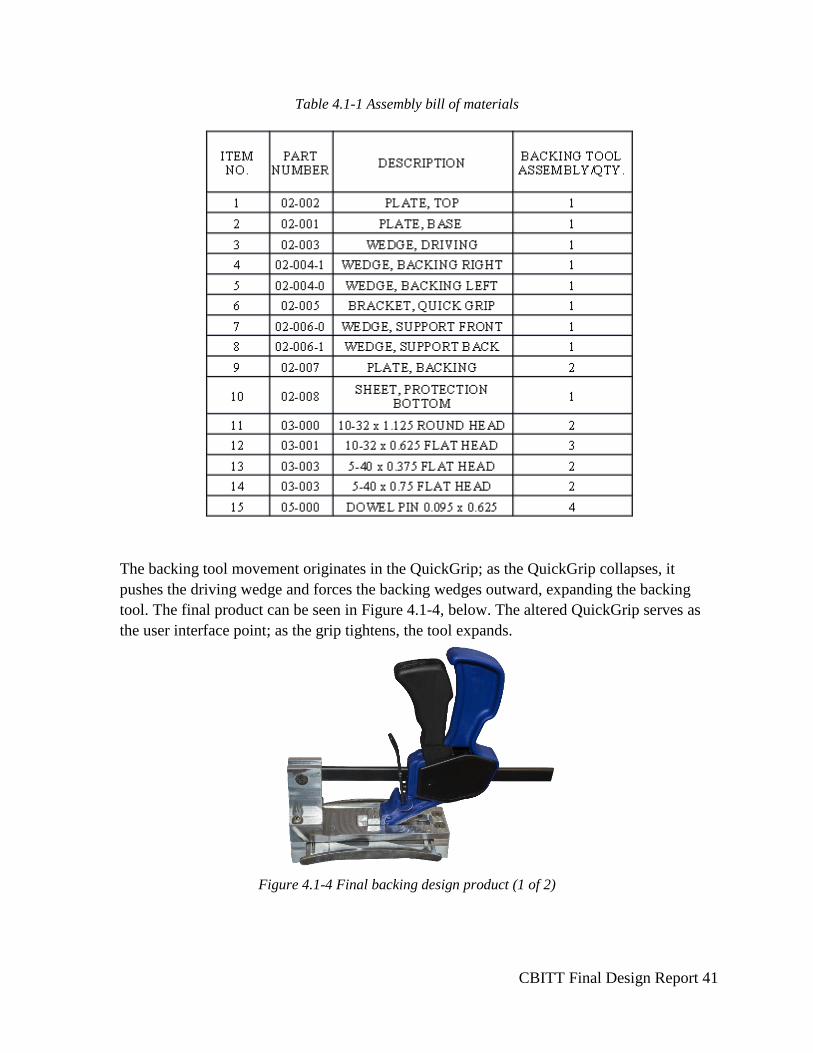
Table 4.1-1 Assembly bill of materials ......................................................................................... 41
Figure 4.1-4 Final backing design product (1 of 2) ...................................................................... 41
Figure 4.1-5 Final backing design product (2 of 2) ...................................................................... 42
Figure 4.1-6 COTS Irwin QuickGrip Mini Bar-Clamp ................................................................ 43
Figure 4.1-7 Solidworks model of expansion driving wedge ....................................................... 43
Figure 4.1-9 Solidworks model of housing top plate .................................................................... 44
Figure 4.1-10 SolidWorks part model of housing base plate ........................................................ 45
Figure 4.1-11 Compressor cross-section (max, min dimensions) with backing tool .................... 45
Figure 4.1-12 Backing wedge at full expansion Von Mises stress under 300lbs ......................... 47
Figure 4.1-13 Driving wedge at full expansion Von Vises stress under 300lbs ........................... 47
Table 4.1-2 Backing tool purchasing bill of materials .................................................................. 48
Figure 4.1-14 Cross-section of T130 compressor, largest and smallest expansion locations noted
....................................................................................................................................................... 49
Figure 4.1-15 Irwin Mini QuickGrip in hand ............................................................................... 50
Figure 4.2-1 Solidworks assembly model of bending tool ........................................................... 52
Figure 4.2-2 Solidworks exploded view of bending tool .............................................................. 53
Table 4.2-1 Bending tool assembly bill of materials .................................................................... 54
Figure 4.2-3 Solidworks exploded view of handle assembly ....................................................... 55
Table 4.2-2 Bending tool handle assembly bill of materials ......................................................... 55
Figure 4.2-4 Installed backing tool showing stage 1 attachment .................................................. 56
Figure 4.2-5 Bending tool final design product ............................................................................ 57
Figure 4.2-6 Solidworks model of bending tooth, stage 1 attachment and corresponding assembly
....................................................................................................................................................... 58
Figure 4.2-7 Solidworks model of bending tool base ................................................................... 58
Figure 4.2-8 Solidworks model showing adjustment systems ...................................................... 59
Figure 4.2-9 Installed backing tool depicting adjustment systems ............................................... 59
Figure 4.2-10 Bending tool, foot Von Mises under 700lbs .......................................................... 60
Figure 4.2-11 First stage attachment Von Mises under 700lbs ..................................................... 60
Table 4.2-3 Bending tool purchasing bill of materials .................................................................. 62
Figure 4.2-12 T130 compressor cross-section with stage one shoulder indicated ........................ 63
Figure 5.1-1 Manufacturing the bottom plate on a mill ................................................................ 66
Figure 5.1-2 Example CNC tool path generated by HSMWorks ................................................. 67
Figure 5.1-3 Child wedge after first CNC operation .................................................................... 67
Figure 5.2-1 Making a vertical support step on a lathe ................................................................. 68
Figure A.1.House of quality for project specifications ................................................................. 74
Table A.1 Morphological matrix for ideation ............................................................................... 75
Table A.2 Design decision matrix for the backing tool ................................................................ 76
Figure A.1.House of quality for project specifications ................................................................. 76
Table A.3 Design decision matrix for the bending tool ................................................................ 77
CBITT Final Design Report 9
Table B.1 Structured bill of materials for bending and backing tools .......................................... 78
Table C.1 Vendor information for purchased parts .................................................................... 109
Figure E.1 Bender foot Von Mises stress under 700lb load ...................................................... 133
Figure E.2 First stage attachment total displacement under 700lb load ..................................... 134
Figure E.3 Bender tooth total displacement under 700lb load .................................................... 135
Figure E.4 Bender foot total displacement under 700lbs ............................................................ 135
Figure F.1. Gantt chart start fall quarter to week 4 winter quarter ............................................. 136
Figure F.2 Gantt chart winter quarter week 5 to end of spring quarter ....................................... 136
Figure G. 7.1-1 Bending Force for a 0.060” SS retainer tab bent at 0.010”/sec ......................... 140
Table G.1 Key Values from run 1 ............................................................................................... 140
Figure G.2 Bending Force for a 0.060” SS retainer tab bent at 0.020”/sec ................................ 141
Table G.2 Key Values from run 2 ............................................................................................... 141
Figure G.3 Bending Force for a 0.050” stage 0 retainer tab bent at 0.020”/sec ......................... 142
Table G.3 Key Values from run 3 ............................................................................................... 142
Figure G.4 Bending Force for a 0.050” stage 0 retainer tab bent at 0.020”/sec ......................... 143
Table G.4 Key Values from run 4 ............................................................................................... 143
Table G.5 Failure mode analysis for the backing and bending tools .......................................... 144
Table G.6 Design verification plans for the backing and bending tools ..................................... 145
Table G.7 Itemized Budget ......................................................................................................... 149
CBITT Final Design Report 10
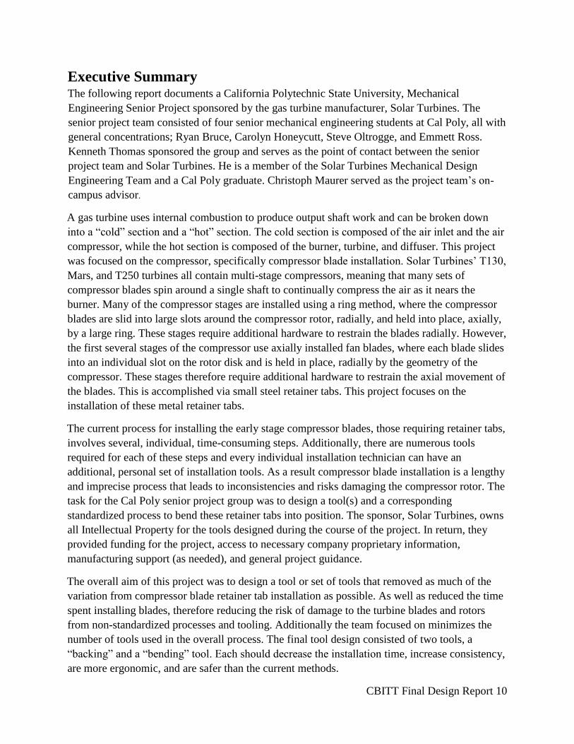
Executive Summary The following report documents a California Polytechnic State University, Mechanical
Engineering Senior Project sponsored by the gas turbine manufacturer, Solar Turbines. The
senior project team consisted of four senior mechanical engineering students at Cal Poly, all with
general concentrations; Ryan Bruce, Carolyn Honeycutt, Steve Oltrogge, and Emmett Ross.
Kenneth Thomas sponsored the group and serves as the point of contact between the senior
project team and Solar Turbines. He is a member of the Solar Turbines Mechanical Design
Engineering Team and a Cal Poly graduate. Christoph Maurer served as the project team’s on-
campus advisor.
A gas turbine uses internal combustion to produce output shaft work and can be broken down
into a “cold” section and a “hot” section. The cold section is composed of the air inlet and the air
compressor, while the hot section is composed of the burner, turbine, and diffuser. This project
was focused on the compressor, specifically compressor blade installation. Solar Turbines’ T130,
Mars, and T250 turbines all contain multi-stage compressors, meaning that many sets of
compressor blades spin around a single shaft to continually compress the air as it nears the
burner. Many of the compressor stages are installed using a ring method, where the compressor
blades are slid into large slots around the compressor rotor, radially, and held into place, axially,
by a large ring. These stages require additional hardware to restrain the blades radially. However,
the first several stages of the compressor use axially installed fan blades, where each blade slides
into an individual slot on the rotor disk and is held in place, radially by the geometry of the
compressor. These stages therefore require additional hardware to restrain the axial movement of
the blades. This is accomplished via small steel retainer tabs. This project focuses on the
installation of these metal retainer tabs.
The current process for installing the early stage compressor blades, those requiring retainer tabs,
involves several, individual, time-consuming steps. Additionally, there are numerous tools
required for each of these steps and every individual installation technician can have an
additional, personal set of installation tools. As a result compressor blade installation is a lengthy
and imprecise process that leads to inconsistencies and risks damaging the compressor rotor. The
task for the Cal Poly senior project group was to design a tool(s) and a corresponding
standardized process to bend these retainer tabs into position. The sponsor, Solar Turbines, owns
all Intellectual Property for the tools designed during the course of the project. In return, they
provided funding for the project, access to necessary company proprietary information,
manufacturing support (as needed), and general project guidance.
The overall aim of this project was to design a tool or set of tools that removed as much of the
variation from compressor blade retainer tab installation as possible. As well as reduced the time
spent installing blades, therefore reducing the risk of damage to the turbine blades and rotors
from non-standardized processes and tooling. Additionally the team focused on minimizes the
number of tools used in the overall process. The final tool design consisted of two tools, a
“backing” and a “bending” tool. Each should decrease the installation time, increase consistency,
are more ergonomic, and are safer than the current methods.
CBITT Final Design Report 11
1. Introduction
1.1. Sponsor Background and Needs
1.1.1.Compressor
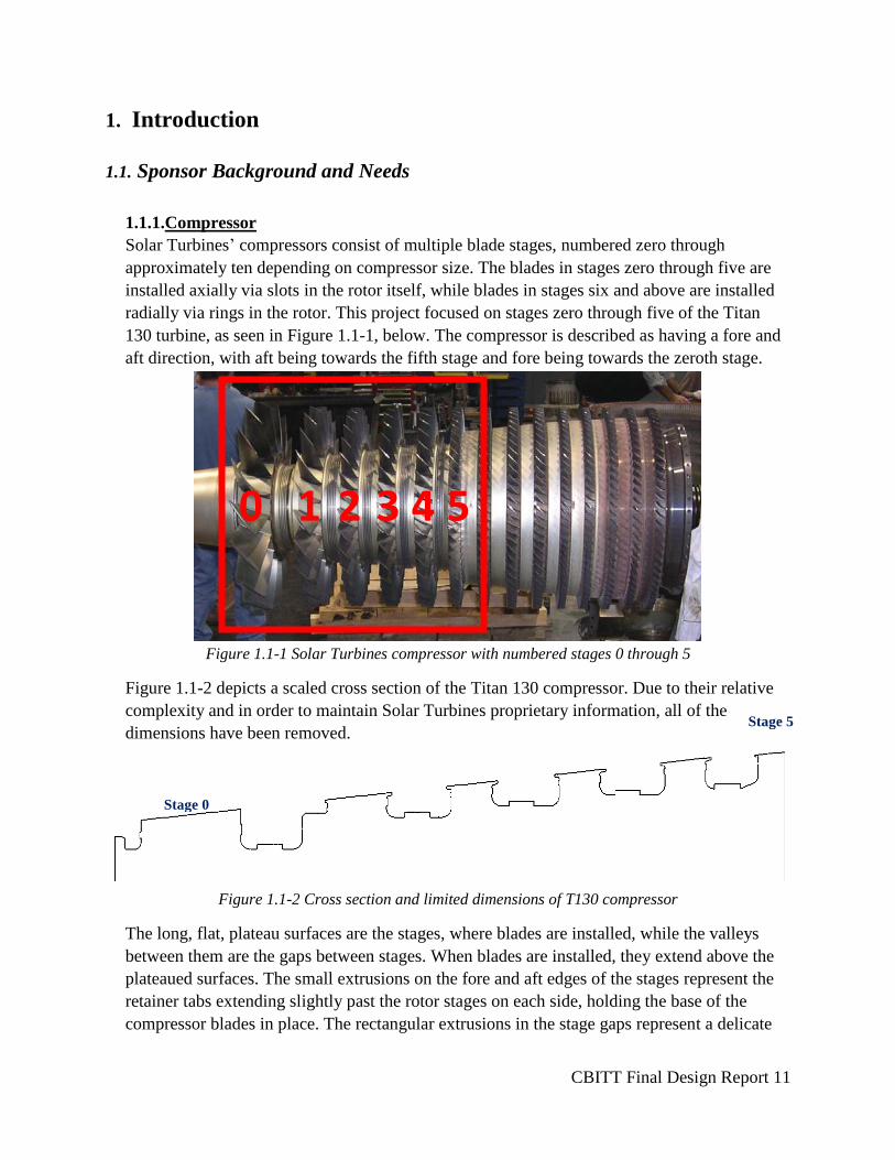
Solar Turbines’ compressors consist of multiple blade stages, numbered zero through
approximately ten depending on compressor size. The blades in stages zero through five are
installed axially via slots in the rotor itself, while blades in stages six and above are installed
radially via rings in the rotor. This project focused on stages zero through five of the Titan
130 turbine, as seen in Figure 1.1-1, below. The compressor is described as having a fore and
aft direction, with aft being towards the fifth stage and fore being towards the zeroth stage.
Figure 1.1-1 Solar Turbines compressor with numbered stages 0 through 5
Figure 1.1-2 depicts a scaled cross section of the Titan 130 compressor. Due to their relative
complexity and in order to maintain Solar Turbines proprietary information, all of the
dimensions have been removed.
Figure 1.1-2 Cross section and limited dimensions of T130 compressor
The long, flat, plateau surfaces are the stages, where blades are installed, while the valleys
between them are the gaps between stages. When blades are installed, they extend above the
plateaued surfaces. The small extrusions on the fore and aft edges of the stages represent the
retainer tabs extending slightly past the rotor stages on each side, holding the base of the
compressor blades in place. The rectangular extrusions in the stage gaps represent a delicate
0 1 2 3 4 5
Stage 0
Stage 5
CBITT Final Design Report 12
seal that runs along the rotor between each stage. The largest gap between stage walls is
between stages 1 and 2 while the smallest gap is between stages 4 and 5; these distances,
respectively, are: 2.61” and 1.69”. The heights between the bottom of the stage gap and the
retainer tabs also differs, with the largest height being 1.431” and the smallest at stage zero of
0.422”.
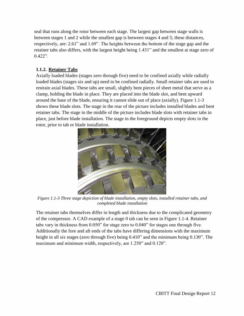
1.1.2. Retainer Tabs
Axially loaded blades (stages zero through five) need to be confined axially while radially
loaded blades (stages six and up) need to be confined radially. Small retainer tabs are used to
restrain axial blades. These tabs are small, slightly bent pieces of sheet metal that serve as a
clamp, holding the blade in place. They are placed into the blade slot, and bent upward
around the base of the blade, ensuring it cannot slide out of place (axially). Figure 1.1-3
shows these blade slots. The stage in the rear of the picture includes installed blades and bent
retainer tabs. The stage in the middle of the picture includes blade slots with retainer tabs in
place, just before blade installation. The stage in the foreground depicts empty slots in the
rotor, prior to tab or blade installation.
Figure 1.1-3 Three stage depiction of blade installation, empty slots, installed retainer tabs, and
completed blade installation
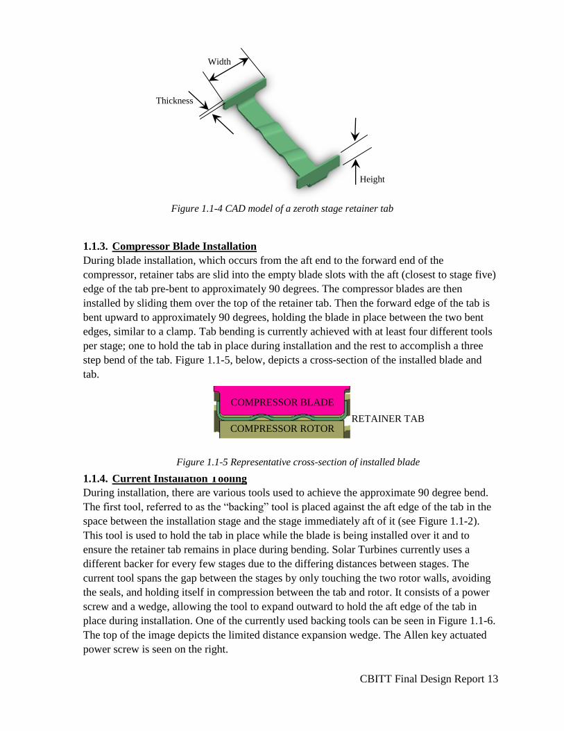
The retainer tabs themselves differ in length and thickness due to the complicated geometry
of the compressor. A CAD example of a stage 0 tab can be seen in Figure 1.1-4. Retainer
tabs vary in thickness from 0.050” for stage zero to 0.040” for stages one through five.
Additionally the fore and aft ends of the tabs have differing dimensions with the maximum
height in all six stages (zero through five) being 0.410” and the minimum being 0.130”. The
maximum and minimum width, respectively, are 1.250” and 0.120”.
CBITT Final Design Report 13
Figure 1.1-4 CAD model of a zeroth stage retainer tab
1.1.3. Compressor Blade Installation
During blade installation, which occurs from the aft end to the forward end of the
compressor, retainer tabs are slid into the empty blade slots with the aft (closest to stage five)
edge of the tab pre-bent to approximately 90 degrees. The compressor blades are then
installed by sliding them over the top of the retainer tab. Then the forward edge of the tab is
bent upward to approximately 90 degrees, holding the blade in place between the two bent
edges, similar to a clamp. Tab bending is currently achieved with at least four different tools
per stage; one to hold the tab in place during installation and the rest to accomplish a three
step bend of the tab. Figure 1.1-5, below, depicts a cross-section of the installed blade and
tab.
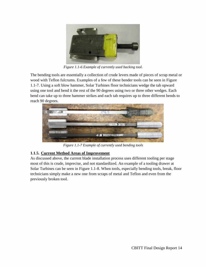
1.1.4. Current Installation Tooling
During installation, there are various tools used to achieve the approximate 90 degree bend.
The first tool, referred to as the “backing” tool is placed against the aft edge of the tab in the
space between the installation stage and the stage immediately aft of it (see Figure 1.1-2).
This tool is used to hold the tab in place while the blade is being installed over it and to
ensure the retainer tab remains in place during bending. Solar Turbines currently uses a
different backer for every few stages due to the differing distances between stages. The
current tool spans the gap between the stages by only touching the two rotor walls, avoiding
the seals, and holding itself in compression between the tab and rotor. It consists of a power
screw and a wedge, allowing the tool to expand outward to hold the aft edge of the tab in
place during installation. One of the currently used backing tools can be seen in Figure 1.1-6.
The top of the image depicts the limited distance expansion wedge. The Allen key actuated
power screw is seen on the right.
Height
Thickness
Width
RETAINER TAB
COMPRESSOR BLADE
COMPRESSOR ROTOR RETAINER TAB
Figure 1.1-5 Representative cross-section of installed blade
CBITT Final Design Report 14
Figure 1.1-6 Example of currently used backing tool.
The bending tools are essentially a collection of crude levers made of pieces of scrap metal or
wood with Teflon fulcrums. Examples of a few of these bender tools can be seen in Figure
1.1-7. Using a soft blow hammer, Solar Turbines floor technicians wedge the tab upward
using one tool and bend it the rest of the 90 degrees using two or three other wedges. Each
bend can take up to three hammer strikes and each tab requires up to three different bends to
reach 90 degrees.
Figure 1.1-7 Example of currently used bending tools
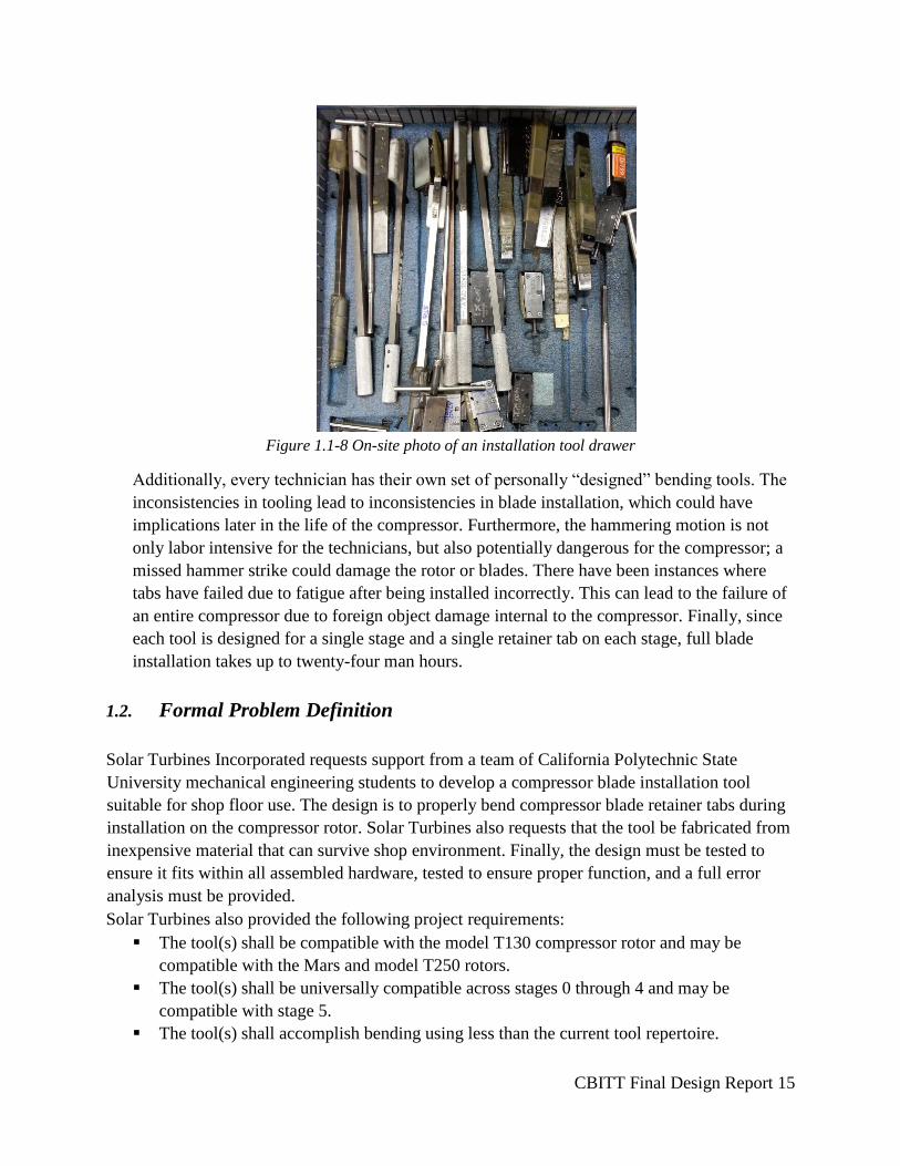
1.1.5. Current Method Areas of Improvement
As discussed above, the current blade installation process uses different tooling per stage
most of this is crude, imprecise, and not standardized. An example of a tooling drawer at
Solar Turbines can be seen in Figure 1.1-8. When tools, especially bending tools, break, floor
technicians simply make a new one from scraps of metal and Teflon and even from the
previously broken tool.
CBITT Final Design Report 15
Figure 1.1-8 On-site photo of an installation tool drawer
Additionally, every technician has their own set of personally “designed” bending tools. The
inconsistencies in tooling lead to inconsistencies in blade installation, which could have
implications later in the life of the compressor. Furthermore, the hammering motion is not
only labor intensive for the technicians, but also potentially dangerous for the compressor; a
missed hammer strike could damage the rotor or blades. There have been instances where
tabs have failed due to fatigue after being installed incorrectly. This can lead to the failure of
an entire compressor due to foreign object damage internal to the compressor. Finally, since
each tool is designed for a single stage and a single retainer tab on each stage, full blade
installation takes up to twenty-four man hours.
1.2. Formal Problem Definition
Solar Turbines Incorporated requests support from a team of California Polytechnic State
University mechanical engineering students to develop a compressor blade installation tool
suitable for shop floor use. The design is to properly bend compressor blade retainer tabs during
installation on the compressor rotor. Solar Turbines also requests that the tool be fabricated from
inexpensive material that can survive shop environment. Finally, the design must be tested to
ensure it fits within all assembled hardware, tested to ensure proper function, and a full error
analysis must be provided.
Solar Turbines also provided the following project requirements:
The tool(s) shall be compatible with the model T130 compressor rotor and may be
compatible with the Mars and model T250 rotors.
The tool(s) shall be universally compatible across stages 0 through 4 and may be
compatible with stage 5.
The tool(s) shall accomplish bending using less than the current tool repertoire.
CBITT Final Design Report 16
The tool(s) shall accomplish bending in less time than the current process.
The tool(s) shall accomplish bending with greater accuracy and consistency than the
current process.
The tool(s) shall not require any changes, modifications, or alterations to any Solar
Turbines design, modifications shall be limited to installation tooling only.
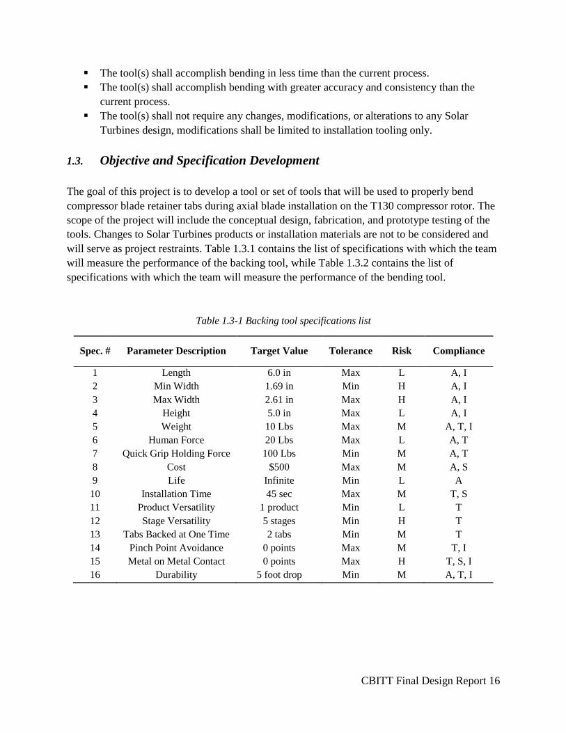
1.3. Objective and Specification Development
The goal of this project is to develop a tool or set of tools that will be used to properly bend
compressor blade retainer tabs during axial blade installation on the T130 compressor rotor. The
scope of the project will include the conceptual design, fabrication, and prototype testing of the
tools. Changes to Solar Turbines products or installation materials are not to be considered and
will serve as project restraints. Table 1.3.1 contains the list of specifications with which the team
will measure the performance of the backing tool, while Table 1.3.2 contains the list of
specifications with which the team will measure the performance of the bending tool.
Table 1.3-1 Backing tool specifications list
Spec. # Parameter Description Target Value Tolerance Risk Compliance
1 Length 6.0 in Max L A, I
2 Min Width 1.69 in Min H A, I
3 Max Width 2.61 in Max H A, I
4 Height 5.0 in Max L A, I
5 Weight 10 Lbs Max M A, T, I
6 Human Force 20 Lbs Max L A, T
7 Quick Grip Holding Force 100 Lbs Min M A, T
8 Cost $500 Max M A, S
9 Life Infinite Min L A
10 Installation Time 45 sec Max M T, S
11 Product Versatility 1 product Min L T
12 Stage Versatility 5 stages Min H T
13 Tabs Backed at One Time 2 tabs Min M T
14 Pinch Point Avoidance 0 points Max M T, I
15 Metal on Metal Contact 0 points Max H T, S, I
16 Durability 5 foot drop Min M A, T, I
CBITT Final Design Report 17
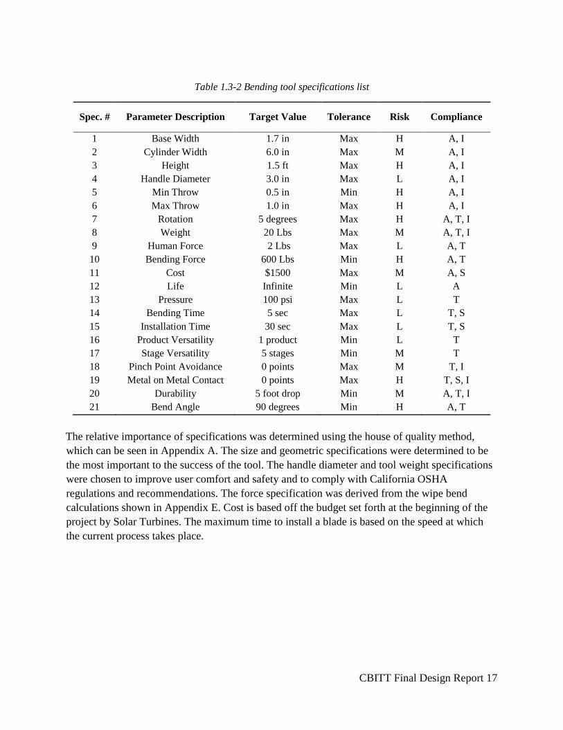
Table 1.3-2 Bending tool specifications list
Spec. # Parameter Description Target Value Tolerance Risk Compliance
1 Base Width 1.7 in Max H A, I
2 Cylinder Width 6.0 in Max M A, I
3 Height 1.5 ft Max H A, I
4 Handle Diameter 3.0 in Max L A, I
5 Min Throw 0.5 in Min H A, I
6 Max Throw 1.0 in Max H A, I
7 Rotation 5 degrees Max H A, T, I
8 Weight 20 Lbs Max M A, T, I
9 Human Force 2 Lbs Max L A, T
10 Bending Force 600 Lbs Min H A, T
11 Cost $1500 Max M A, S
12 Life Infinite Min L A
13 Pressure 100 psi Max L T
14 Bending Time 5 sec Max L T, S
15 Installation Time 30 sec Max L T, S
16 Product Versatility 1 product Min L T
17 Stage Versatility 5 stages Min M T
18 Pinch Point Avoidance 0 points Max M T, I
19 Metal on Metal Contact 0 points Max H T, S, I
20
21
Durability
Bend Angle
5 foot drop
90 degrees
Min
Min
M
H
A, T, I
A, T
The relative importance of specifications was determined using the house of quality method,
which can be seen in Appendix A. The size and geometric specifications were determined to be
the most important to the success of the tool. The handle diameter and tool weight specifications
were chosen to improve user comfort and safety and to comply with California OSHA
regulations and recommendations. The force specification was derived from the wipe bend
calculations shown in Appendix E. Cost is based off the budget set forth at the beginning of the
project by Solar Turbines. The maximum time to install a blade is based on the speed at which
the current process takes place.

CBITT Final Design Report 18
2. Background Research
The majority of the information pertinent to the design of the tool(s) was provided by Solar
Turbines. This included a statement of work, list of deliverables, as well as retainer and
necessary compressor dimensions.
2.1. Solar Turbines Site Visit
The project group visited Solar Turbines in San Diego on October 9, 2015 to observe first-hand
the current installation processes described above, including watching and interviewing a floor
technician as he installed compressor blades. In interviewing the technician, the team was able to
observe the culture among the floor technicians especially concerning their overall advertence to
process or status quo changes. The team discovered that a previous Solar Turbines-Cal Poly
senior project went unused because the device required many changes to the mechanic’s current
processes. While this project was functional and quite innovative, it went to waste simply
because the technicians did not choose to accept it in their day-to-day work. The interview with
the technician also gave the team a chance to learn what made certain tools favorable when
compared to others. Asking the technician which tools he used most frequently, why he preferred
his own set of tools, and what he thought could be improved in the installation process provided
insight into the overall installation process and to the easiest way to achieve tab bending.
2.2. Patent Research and Existing Products
Most of the background patent research conducted included looking into patents and the online
Combined Cycle Journal. However, the scope of this project consists of installation processes
and tooling, which tend to be company proprietary information and was unavailable in the patent
search. The team found patents on compressor rotor design, compressor blade design, and
retainer tab design, but was unable to locate any patents specifically relating to processes. Since
changes to Solar Turbines’ installation process or their designs was beyond the scope of the
project, the team chose to abandon patent research.
For a description of the current process used at Solar Turbines, see Introduction.
2.3. Occupational Safety and Health Administration Research
Furthermore, the team researched California Occupational Safety and Health Administration
(OSHA) requirements, restrictions, and guidelines as they pertained to upper body exertion.
OSHA states that workers should not exert more than 42lbs of force from their upper body when
the motion is repetitive. This lead to a developed requirement, that the designed tool must not
require the floor technician to exert more than 30lbs of force in order to appropriately use the
CBITT Final Design Report 19
tool. The team also researched OSHA safety procedures required to approve floor processes,
however this was also beyond the scope of the project.
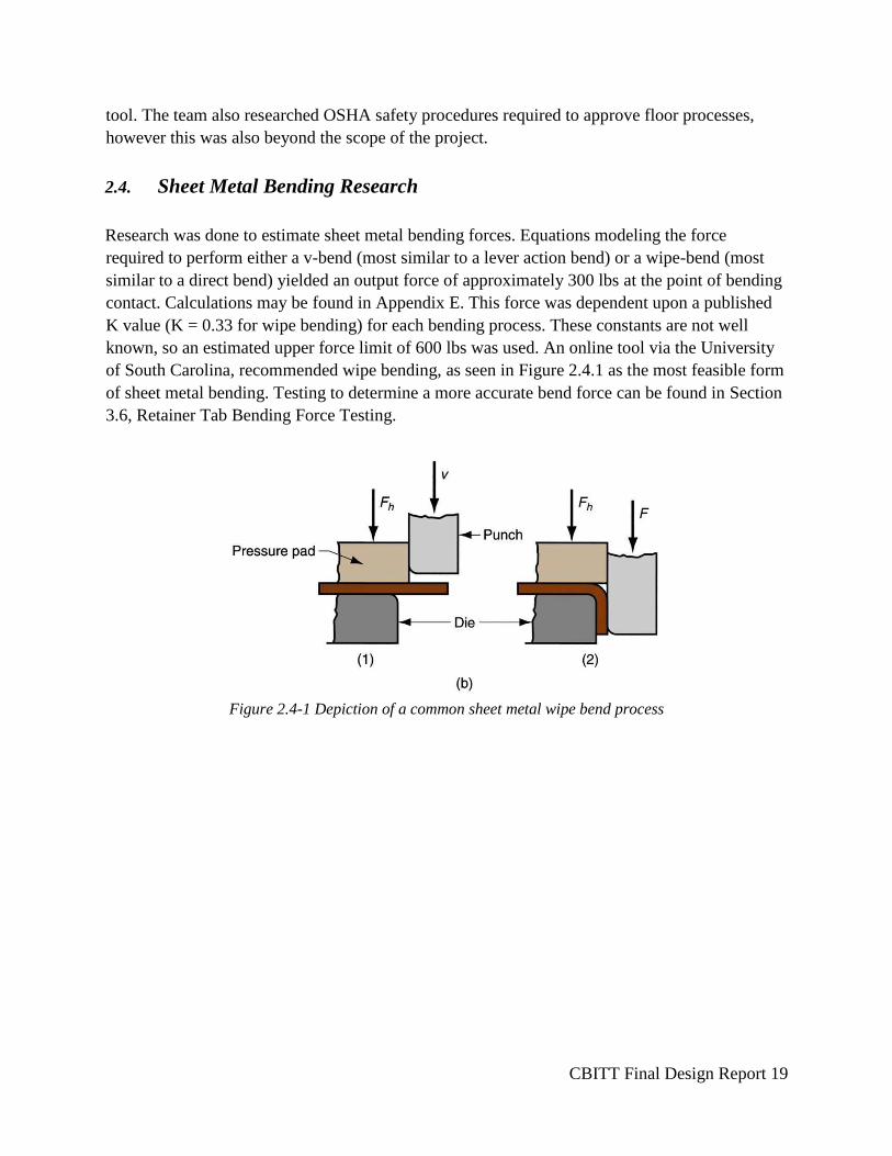
2.4. Sheet Metal Bending Research
Research was done to estimate sheet metal bending forces. Equations modeling the force
required to perform either a v-bend (most similar to a lever action bend) or a wipe-bend (most
similar to a direct bend) yielded an output force of approximately 300 lbs at the point of bending
contact. Calculations may be found in Appendix E. This force was dependent upon a published
K value (K = 0.33 for wipe bending) for each bending process. These constants are not well
known, so an estimated upper force limit of 600 lbs was used. An online tool via the University
of South Carolina, recommended wipe bending, as seen in Figure 2.4.1 as the most feasible form
of sheet metal bending. Testing to determine a more accurate bend force can be found in Section
3.6, Retainer Tab Bending Force Testing.
Figure 2.4-1 Depiction of a common sheet metal wipe bend process
CBITT Final Design Report 20
3. Design Development
3.1. Ideation
The finalized backer and bender were developed using the standard engineering design process.
Since the project involved designing two separate, but related tools, the team completed the
design process on each tool individually, in parallel with the other tool. At each stage in the
process, however, the team ensured that the two tools still functioned together. Ideation and
brainstorming were conducted through a Morphologic matrix (see Appendix A). The matrix lead
to fourteen designs (approximately seven for each tool) being further developed into large format
sketches. A few of these were then roughly developed in SolidWorks.
3.2. Conceptual Designs Discussion
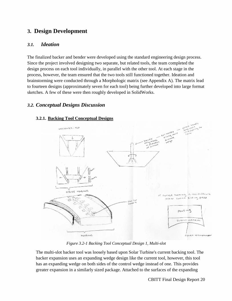
3.2.1. Backing Tool Conceptual Designs
Figure 3.2-1 Backing Tool Conceptual Design 1, Multi-slot
The multi-slot backer tool was loosely based upon Solar Turbine's current backing tool. The
backer expansion uses an expanding wedge design like the current tool, however, this tool
has an expanding wedge on both sides of the control wedge instead of one. This provides
greater expansion in a similarly sized package. Attached to the surfaces of the expanding
CBITT Final Design Report 21
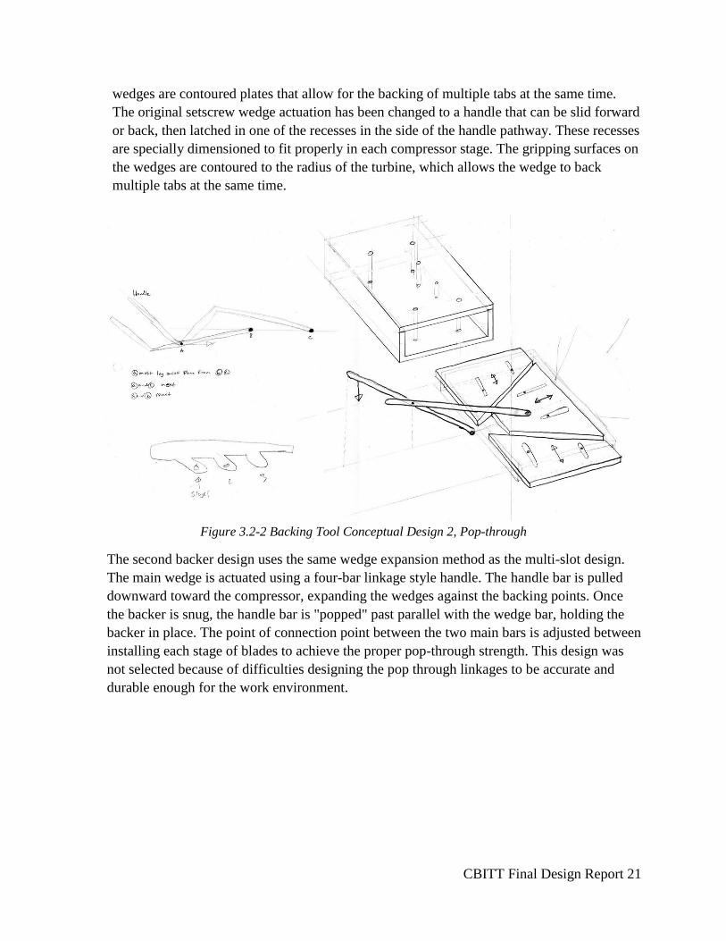
wedges are contoured plates that allow for the backing of multiple tabs at the same time.
The original setscrew wedge actuation has been changed to a handle that can be slid forward
or back, then latched in one of the recesses in the side of the handle pathway. These recesses
are specially dimensioned to fit properly in each compressor stage. The gripping surfaces on
the wedges are contoured to the radius of the turbine, which allows the wedge to back
multiple tabs at the same time.
Figure 3.2-2 Backing Tool Conceptual Design 2, Pop-through
The second backer design uses the same wedge expansion method as the multi-slot design.
The main wedge is actuated using a four-bar linkage style handle. The handle bar is pulled
downward toward the compressor, expanding the wedges against the backing points. Once
the backer is snug, the handle bar is "popped" past parallel with the wedge bar, holding the
backer in place. The point of connection point between the two main bars is adjusted between
installing each stage of blades to achieve the proper pop-through strength. This design was
not selected because of difficulties designing the pop through linkages to be accurate and
durable enough for the work environment.
CBITT Final Design Report 22
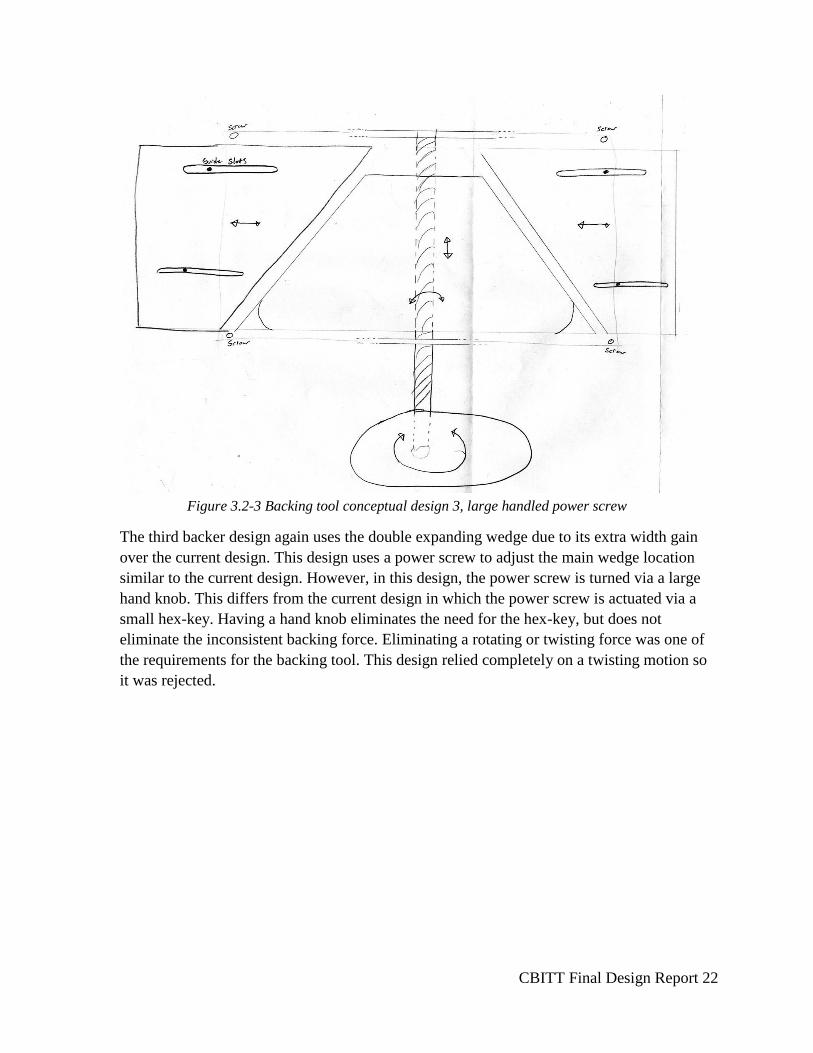
Figure 3.2-3 Backing tool conceptual design 3, large handled power screw
The third backer design again uses the double expanding wedge due to its extra width gain
over the current design. This design uses a power screw to adjust the main wedge location
similar to the current design. However, in this design, the power screw is turned via a large
hand knob. This differs from the current design in which the power screw is actuated via a
small hex-key. Having a hand knob eliminates the need for the hex-key, but does not
eliminate the inconsistent backing force. Eliminating a rotating or twisting force was one of
the requirements for the backing tool. This design relied completely on a twisting motion so
it was rejected.
CBITT Final Design Report 23
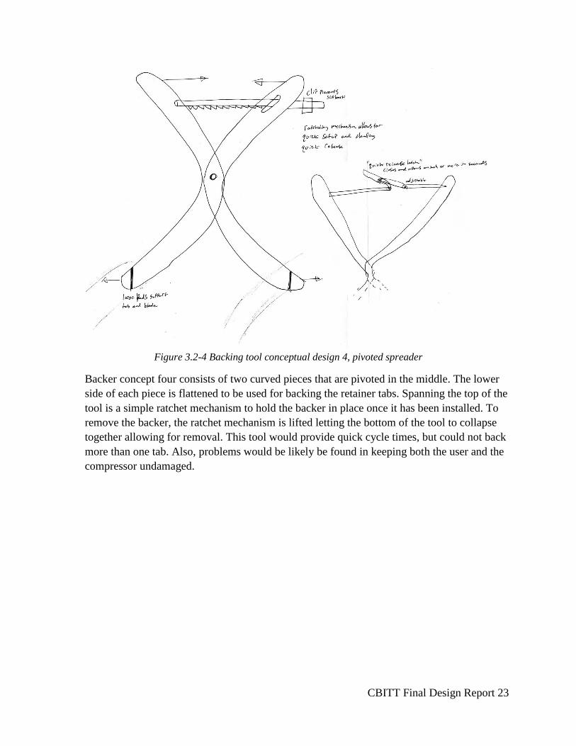
Figure 3.2-4 Backing tool conceptual design 4, pivoted spreader
Backer concept four consists of two curved pieces that are pivoted in the middle. The lower
side of each piece is flattened to be used for backing the retainer tabs. Spanning the top of the
tool is a simple ratchet mechanism to hold the backer in place once it has been installed. To
remove the backer, the ratchet mechanism is lifted letting the bottom of the tool to collapse
together allowing for removal. This tool would provide quick cycle times, but could not back
more than one tab. Also, problems would be likely be found in keeping both the user and the
compressor undamaged.
CBITT Final Design Report 24
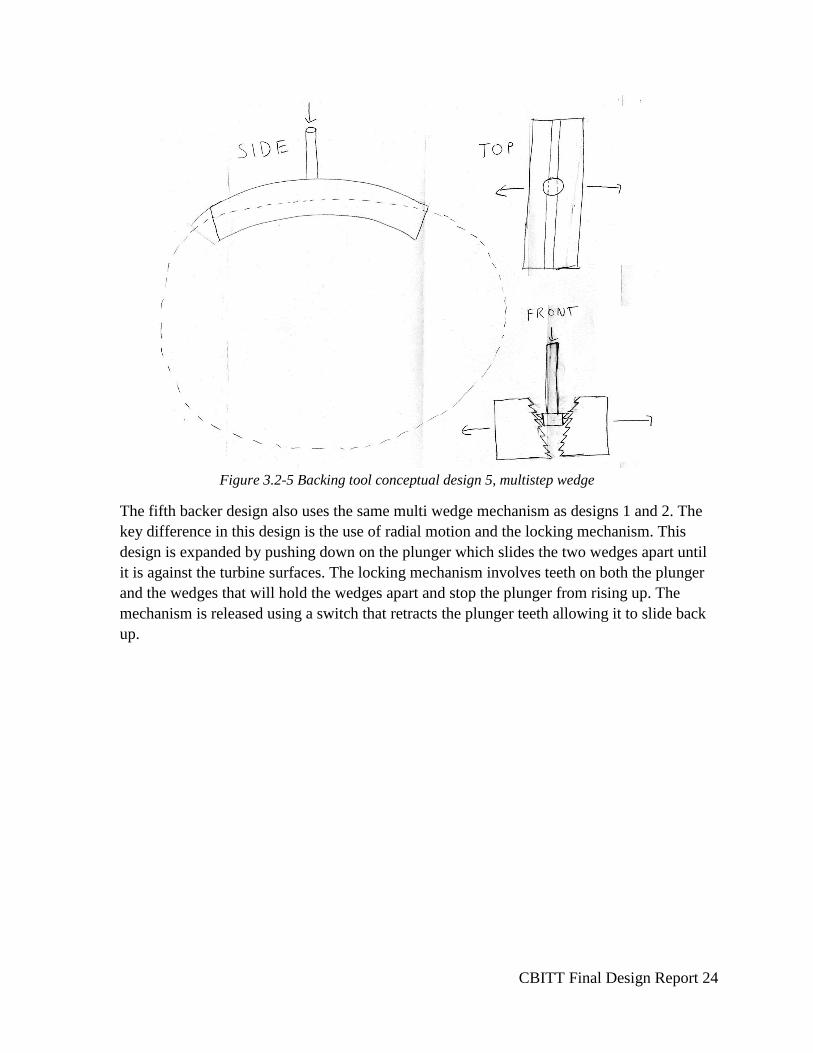
Figure 3.2-5 Backing tool conceptual design 5, multistep wedge
The fifth backer design also uses the same multi wedge mechanism as designs 1 and 2. The
key difference in this design is the use of radial motion and the locking mechanism. This
design is expanded by pushing down on the plunger which slides the two wedges apart until
it is against the turbine surfaces. The locking mechanism involves teeth on both the plunger
and the wedges that will hold the wedges apart and stop the plunger from rising up. The
mechanism is released using a switch that retracts the plunger teeth allowing it to slide back
up.
CBITT Final Design Report 25
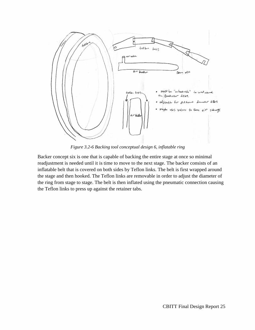
Figure 3.2-6 Backing tool conceptual design 6, inflatable ring
Backer concept six is one that is capable of backing the entire stage at once so minimal
readjustment is needed until it is time to move to the next stage. The backer consists of an
inflatable belt that is covered on both sides by Teflon links. The belt is first wrapped around
the stage and then hooked. The Teflon links are removable in order to adjust the diameter of
the ring from stage to stage. The belt is then inflated using the pneumatic connection causing
the Teflon links to press up against the retainer tabs.
CBITT Final Design Report 26
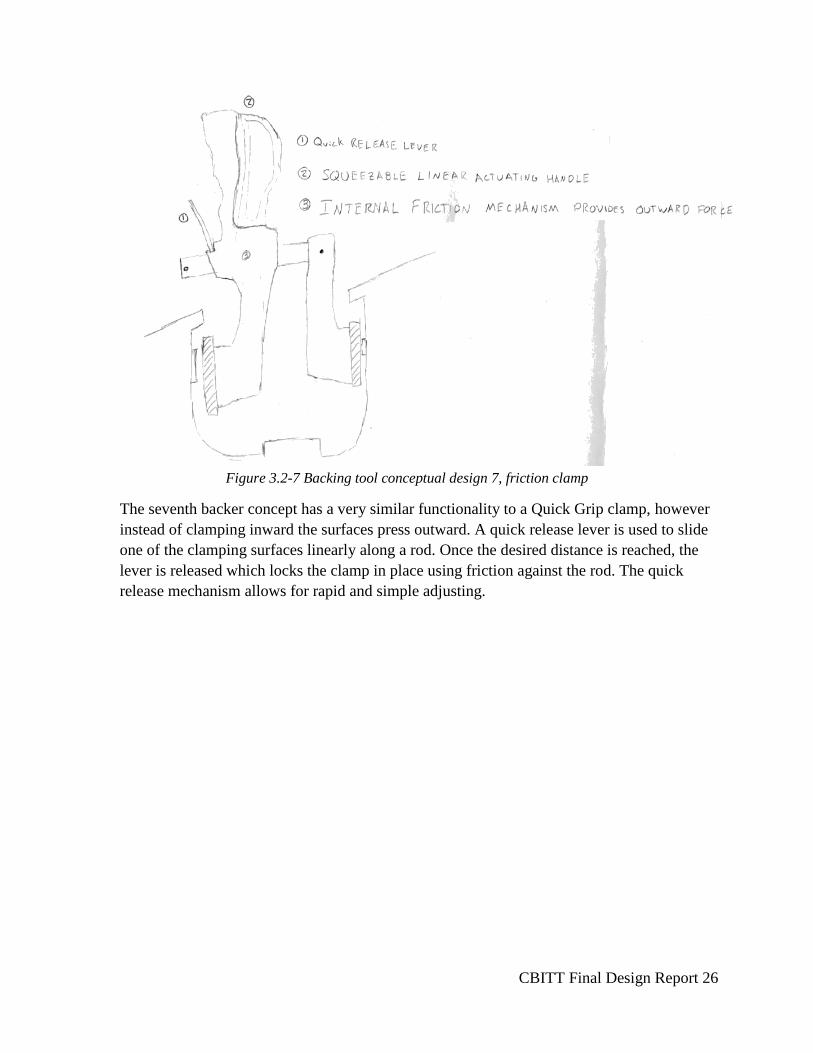
Figure 3.2-7 Backing tool conceptual design 7, friction clamp
The seventh backer concept has a very similar functionality to a Quick Grip clamp, however
instead of clamping inward the surfaces press outward. A quick release lever is used to slide
one of the clamping surfaces linearly along a rod. Once the desired distance is reached, the
lever is released which locks the clamp in place using friction against the rod. The quick
release mechanism allows for rapid and simple adjusting.
CBITT Final Design Report 27
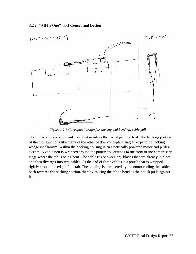
3.2.2. “All-In-One” Tool Conceptual Design
Figure 3.2-8 Conceptual design for backing and bending, cable pull.
The above concept is the only one that involves the use of just one tool. The backing portion
of the tool functions like many of the other backer concepts, using an expanding locking
wedge mechanism. Within the backing housing is an electrically powered motor and pulley
system. A cable/belt is wrapped around the pulley and extends to the front of the compressor
stage where the tab is being bent. The cable fits between any blades that are already in place
and then diverges into two cables. At the end of these cables is a pouch that is wrapped
tightly around the edge of the tab. The bending is completed by the motor reeling the cables
back towards the backing section, thereby causing the tab to bend as the pouch pulls against
it.
CBITT Final Design Report 28
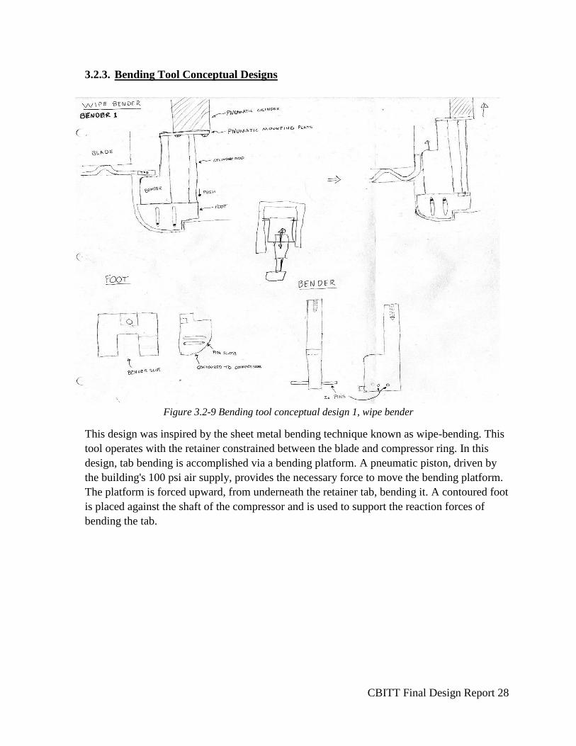
3.2.3. Bending Tool Conceptual Designs
Figure 3.2-9 Bending tool conceptual design 1, wipe bender
This design was inspired by the sheet metal bending technique known as wipe-bending. This
tool operates with the retainer constrained between the blade and compressor ring. In this
design, tab bending is accomplished via a bending platform. A pneumatic piston, driven by
the building's 100 psi air supply, provides the necessary force to move the bending platform.
The platform is forced upward, from underneath the retainer tab, bending it. A contoured foot
is placed against the shaft of the compressor and is used to support the reaction forces of
bending the tab.
CBITT Final Design Report 29
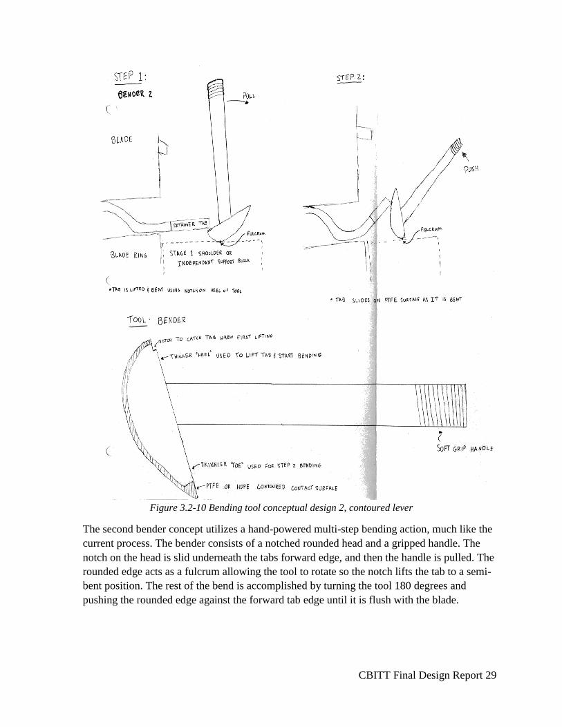
Figure 3.2-10 Bending tool conceptual design 2, contoured lever
The second bender concept utilizes a hand-powered multi-step bending action, much like the
current process. The bender consists of a notched rounded head and a gripped handle. The
notch on the head is slid underneath the tabs forward edge, and then the handle is pulled. The
rounded edge acts as a fulcrum allowing the tool to rotate so the notch lifts the tab to a semi-
bent position. The rest of the bend is accomplished by turning the tool 180 degrees and
pushing the rounded edge against the forward tab edge until it is flush with the blade.
CBITT Final Design Report 30
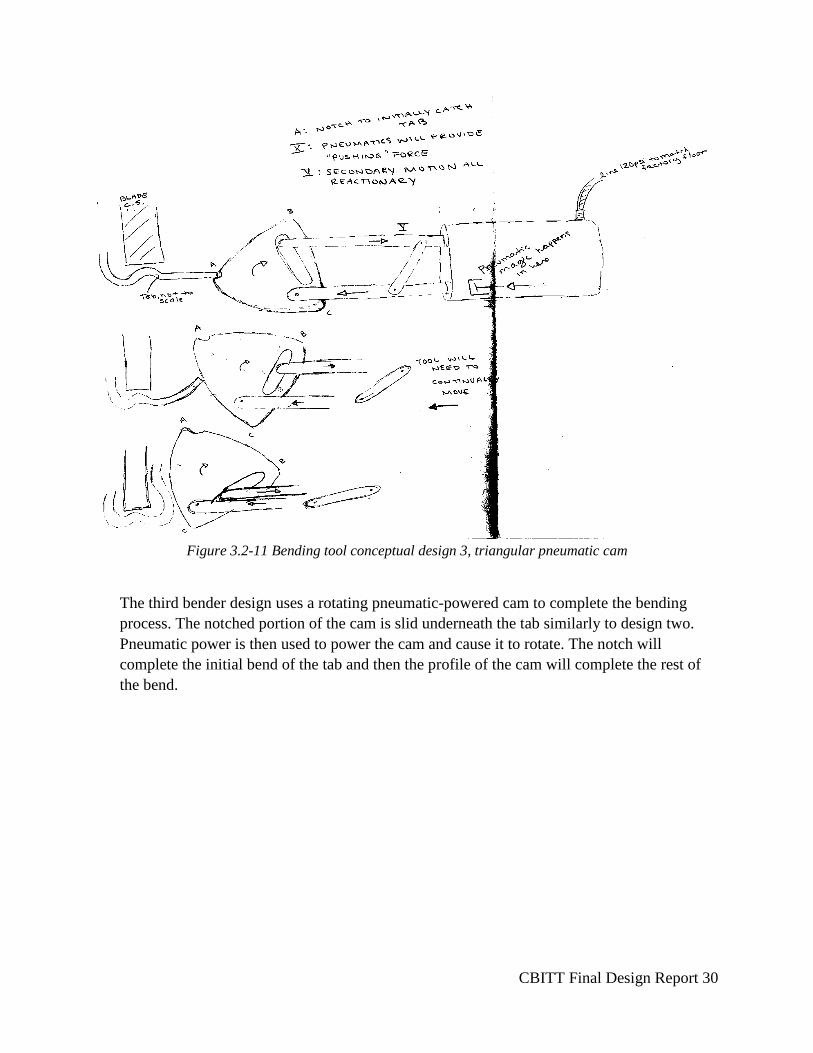
Figure 3.2-11 Bending tool conceptual design 3, triangular pneumatic cam
The third bender design uses a rotating pneumatic-powered cam to complete the bending
process. The notched portion of the cam is slid underneath the tab similarly to design two.
Pneumatic power is then used to power the cam and cause it to rotate. The notch will
complete the initial bend of the tab and then the profile of the cam will complete the rest of
the bend.
CBITT Final Design Report 31
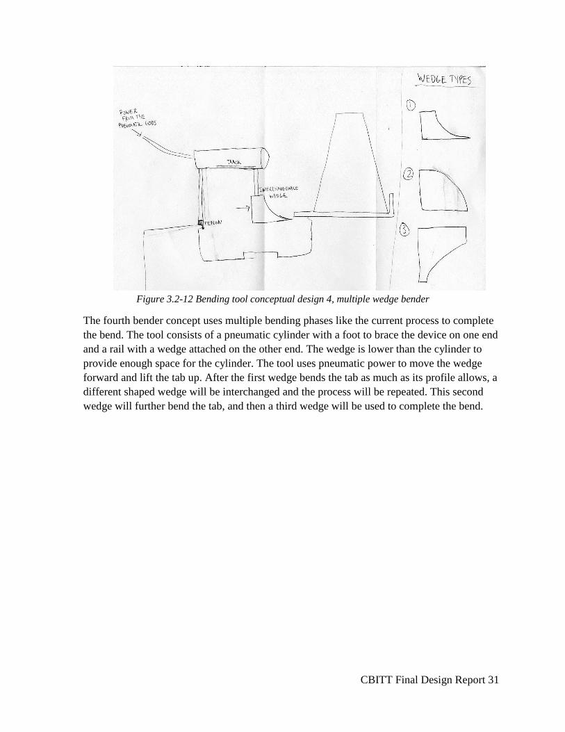
Figure 3.2-12 Bending tool conceptual design 4, multiple wedge bender
The fourth bender concept uses multiple bending phases like the current process to complete
the bend. The tool consists of a pneumatic cylinder with a foot to brace the device on one end
and a rail with a wedge attached on the other end. The wedge is lower than the cylinder to
provide enough space for the cylinder. The tool uses pneumatic power to move the wedge
forward and lift the tab up. After the first wedge bends the tab as much as its profile allows, a
different shaped wedge will be interchanged and the process will be repeated. This second
wedge will further bend the tab, and then a third wedge will be used to complete the bend.
CBITT Final Design Report 32
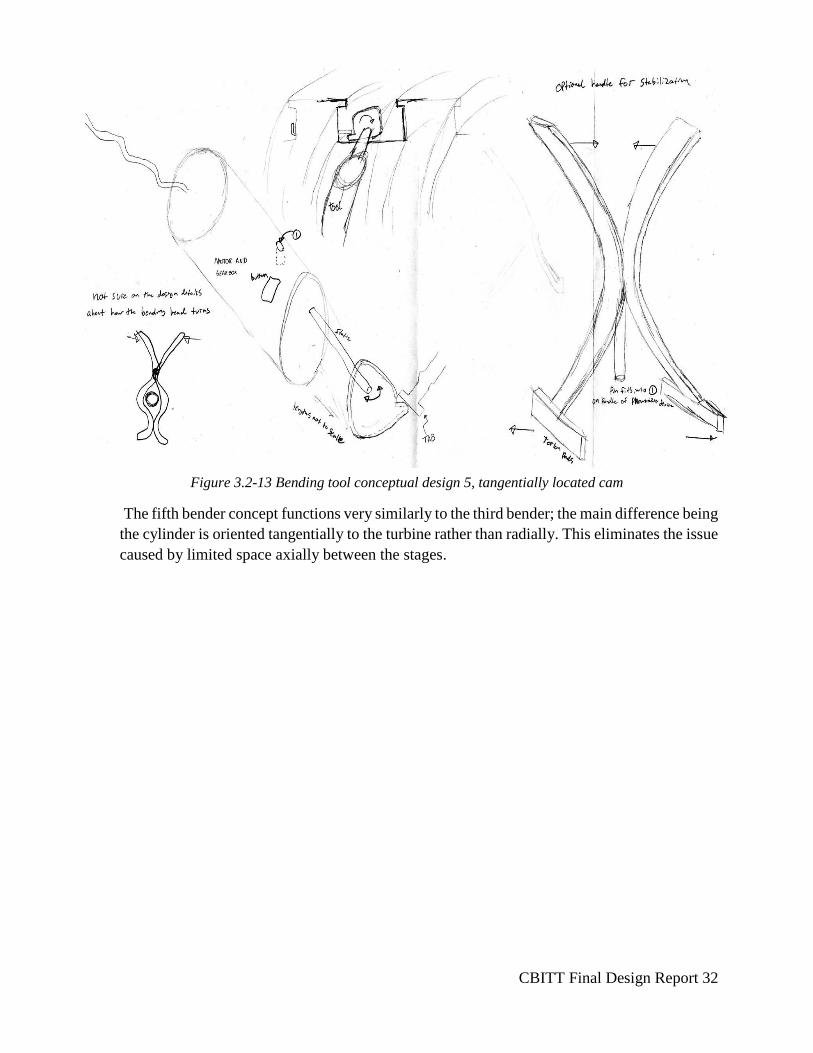
The fifth bender concept functions very similarly to the third bender; the main difference being
the cylinder is oriented tangentially to the turbine rather than radially. This eliminates the issue
caused by limited space axially between the stages.
Figure 3.2-13 Bending tool conceptual design 5, tangentially located cam
CBITT Final Design Report 33
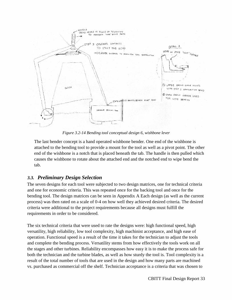
Figure 3.2-14 Bending tool conceptual design 6, wishbone lever
The last bender concept is a hand operated wishbone bender. One end of the wishbone is
attached to the bending tool to provide a mount for the tool as well as a pivot point. The other
end of the wishbone is a notch that is placed beneath the tab. The handle is then pulled which
causes the wishbone to rotate about the attached end and the notched end to wipe bend the
tab.
3.3. Preliminary Design Selection
The seven designs for each tool were subjected to two design matrices, one for technical criteria
and one for economic criteria. This was repeated once for the backing tool and once for the
bending tool. The design matrices can be seen in Appendix A Each design (as well as the current
process) was then rated on a scale of 0-4 on how well they achieved desired criteria. The desired
criteria were additional to the project requirements because all designs must fulfill the
requirements in order to be considered.
The six technical criteria that were used to rate the designs were: high functional speed, high
versatility, high reliability, low tool complexity, high machinist acceptance, and high ease of
operation. Functional speed is a result of the time it takes for the technician to adjust the tools
and complete the bending process. Versatility stems from how effectively the tools work on all
the stages and other turbines. Reliability encompasses how easy it is to make the process safe for
both the technician and the turbine blades, as well as how sturdy the tool is. Tool complexity is a
result of the total number of tools that are used in the design and how many parts are machined
vs. purchased as commercial off the shelf. Technician acceptance is a criteria that was chosen to
CBITT Final Design Report 34
be by itself because it was agreed to have great importance. In learning about past attempts to
create tools for the technicians it was discovered that many tools that were created are not used
even though they function adequately. The reason for this is that the technicians do not like using
the tool and therefore elect to use their old tools over it. This design should be a tool that the
machinists will have a desire to use. Lastly, ease of operation encompasses the physical exertion
the technician goes through when using the tool, as well as how easily the tool is adjusted and
utilized.
The five economic criteria that were considered are: low labor costs, low manufacturing costs,
low cost of raw materials, low cost of purchased parts, and low development cost. These criteria
factor in cost at all points in the design process to show which designs will be more
economically desirable at all stages.
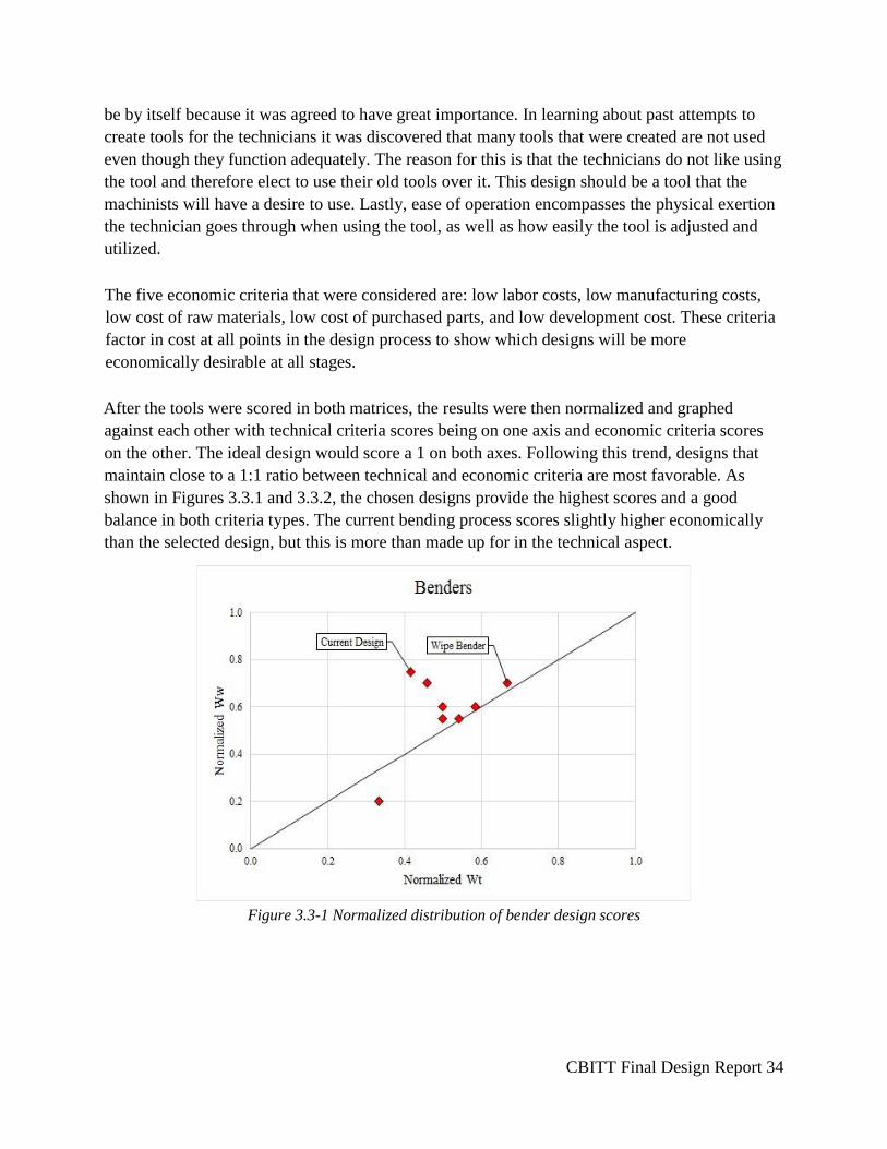
After the tools were scored in both matrices, the results were then normalized and graphed
against each other with technical criteria scores being on one axis and economic criteria scores
on the other. The ideal design would score a 1 on both axes. Following this trend, designs that
maintain close to a 1:1 ratio between technical and economic criteria are most favorable. As
shown in Figures 3.3.1 and 3.3.2, the chosen designs provide the highest scores and a good
balance in both criteria types. The current bending process scores slightly higher economically
than the selected design, but this is more than made up for in the technical aspect.
Figure 3.3-1 Normalized distribution of bender design scores
CBITT Final Design Report 35
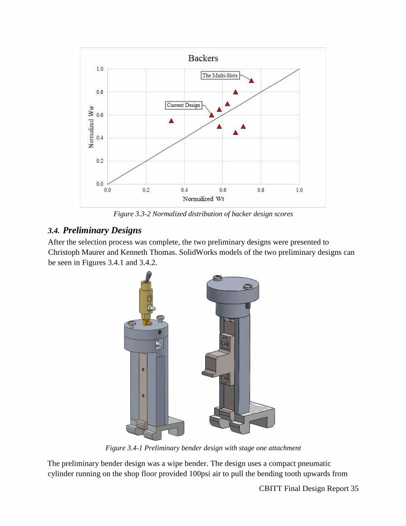
Figure 3.3-2 Normalized distribution of backer design scores
3.4. Preliminary Designs
After the selection process was complete, the two preliminary designs were presented to
Christoph Maurer and Kenneth Thomas. SolidWorks models of the two preliminary designs can
be seen in Figures 3.4.1 and 3.4.2.
Figure 3.4-1 Preliminary bender design with stage one attachment
The preliminary bender design was a wipe bender. The design uses a compact pneumatic
cylinder running on the shop floor provided 100psi air to pull the bending tooth upwards from
CBITT Final Design Report 36
underneath of the un-bent retainer tab. This will perform a wipe bend snugly against the blade.
The base of the tool was designed to fit over the sensitive steel that wraps around all of the stage
transition gaps. The feet of the base are designed to fit in the curvature of all of the stages. To
bend the retaining tabs on the first stage of the compressor, the bending tool must reach on top of
a large shoulder. This is done by the addition of a first stage bending attachment. This attachment
is fastened to the main bender bar using two countersunk screws.
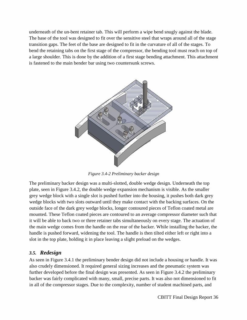
Figure 3.4-2 Preliminary backer design
The preliminary backer design was a multi-slotted, double wedge design. Underneath the top
plate, seen in Figure 3.4.2, the double wedge expansion mechanism is visible. As the smaller
grey wedge block with a single slot is pushed further into the housing, it pushes both dark grey
wedge blocks with two slots outward until they make contact with the backing surfaces. On the
outside face of the dark grey wedge blocks, longer contoured pieces of Teflon coated metal are
mounted. These Teflon coated pieces are contoured to an average compressor diameter such that
it will be able to back two or three retainer tabs simultaneously on every stage. The actuation of
the main wedge comes from the handle on the rear of the backer. While installing the backer, the
handle is pushed forward, widening the tool. The handle is then tilted either left or right into a
slot in the top plate, holding it in place leaving a slight preload on the wedges.
3.5. Redesign
As seen in Figure 3.4.1 the preliminary bender design did not include a housing or handle. It was
also crudely dimensioned. It required general sizing increases and the pneumatic system was
further developed before the final design was presented. As seen in Figure 3.4.2 the preliminary
backer was fairly complicated with many, small, precise parts. It was also not dimensioned to fit
in all of the compressor stages. Due to the complexity, number of student machined parts, and
CBITT Final Design Report 37
the lack of mechanical advantage, the backer underwent a full redesign process before the final
design was developed and presented. See Section 4 for a full description of the final designs
3.6. Retainer Tab Bending Force Testing
Prior to the preliminary design report (PDR), the required bending force was approximated using
sheet metal bending calculations, which can be found in Appendix E and Section 2.4 Sheet
Metal Bending Research. In order to continue into the final design, the exact force-to-bend for
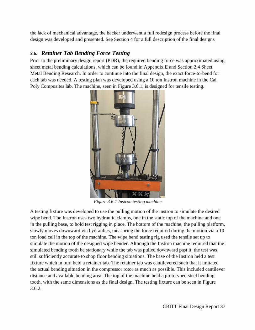
each tab was needed. A testing plan was developed using a 10 ton Instron machine in the Cal
Poly Composites lab. The machine, seen in Figure 3.6.1, is designed for tensile testing.
Figure 3.6-1 Instron testing machine
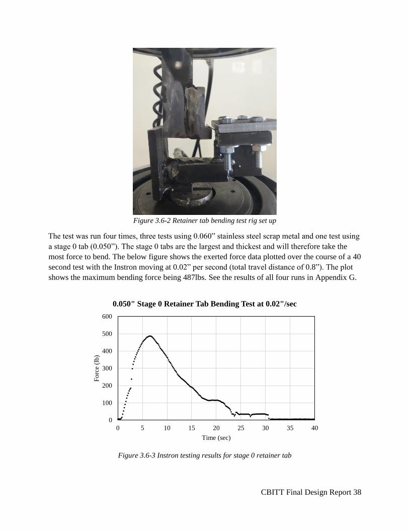
A testing fixture was developed to use the pulling motion of the Instron to simulate the desired
wipe bend. The Instron uses two hydraulic clamps, one in the static top of the machine and one
in the pulling base, to hold test rigging in place. The bottom of the machine, the pulling platform,
slowly moves downward via hydraulics, measuring the force required during the motion via a 10
ton load cell in the top of the machine. The wipe bend testing rig used the tensile set up to
simulate the motion of the designed wipe bender. Although the Instron machine required that the
simulated bending tooth be stationary while the tab was pulled downward past it, the test was
still sufficiently accurate to shop floor bending situations. The base of the Instron held a test
fixture which in turn held a retainer tab. The retainer tab was cantilevered such that it imitated
the actual bending situation in the compressor rotor as much as possible. This included cantilever
distance and available bending area. The top of the machine held a prototyped steel bending
tooth, with the same dimensions as the final design. The testing fixture can be seen in Figure
3.6.2.
CBITT Final Design Report 38
Figure 3.6-2 Retainer tab bending test rig set up
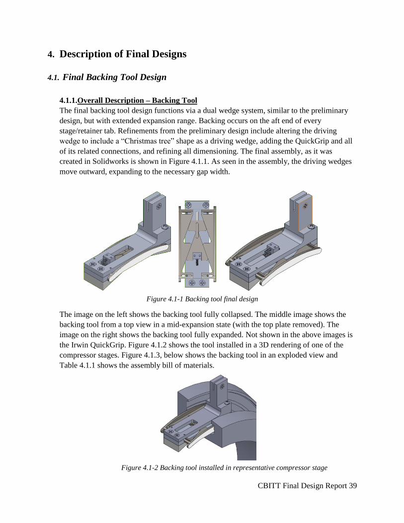
The test was run four times, three tests using 0.060” stainless steel scrap metal and one test using
a stage 0 tab (0.050”). The stage 0 tabs are the largest and thickest and will therefore take the
most force to bend. The below figure shows the exerted force data plotted over the course of a 40
second test with the Instron moving at 0.02” per second (total travel distance of 0.8”). The plot
shows the maximum bending force being 487lbs. See the results of all four runs in Appendix G.
Figure 3.6-3 Instron testing results for stage 0 retainer tab
0
100
200
300
400
500
600
0 5 10 15 20 25 30 35 40
Fo
rce
(lb
)
Time (sec)
0.050" Stage 0 Retainer Tab Bending Test at 0.02"/sec
CBITT Final Design Report 39
4. Description of Final Designs
4.1. Final Backing Tool Design
4.1.1.Overall Description – Backing Tool
The final backing tool design functions via a dual wedge system, similar to the preliminary
design, but with extended expansion range. Backing occurs on the aft end of every
stage/retainer tab. Refinements from the preliminary design include altering the driving
wedge to include a “Christmas tree” shape as a driving wedge, adding the QuickGrip and all
of its related connections, and refining all dimensioning. The final assembly, as it was
created in Solidworks is shown in Figure 4.1.1. As seen in the assembly, the driving wedges
move outward, expanding to the necessary gap width.
Figure 4.1-1 Backing tool final design
The image on the left shows the backing tool fully collapsed. The middle image shows the
backing tool from a top view in a mid-expansion state (with the top plate removed). The
image on the right shows the backing tool fully expanded. Not shown in the above images is
the Irwin QuickGrip. Figure 4.1.2 shows the tool installed in a 3D rendering of one of the
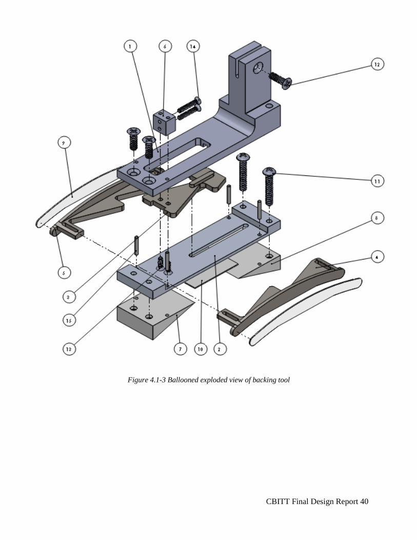
compressor stages. Figure 4.1.3, below shows the backing tool in an exploded view and
Table 4.1.1 shows the assembly bill of materials.
Figure 4.1-2 Backing tool installed in representative compressor stage
CBITT Final Design Report 40
Figure 4.1-3 Ballooned exploded view of backing tool
CBITT Final Design Report 41
Table 4.1-1 Assembly bill of materials
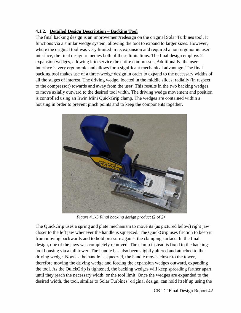
The backing tool movement originates in the QuickGrip; as the QuickGrip collapses, it
pushes the driving wedge and forces the backing wedges outward, expanding the backing
tool. The final product can be seen in Figure 4.1-4, below. The altered QuickGrip serves as
the user interface point; as the grip tightens, the tool expands.
Figure 4.1-4 Final backing design product (1 of 2)
CBITT Final Design Report 42
4.1.2. Detailed Design Description – Backing Tool
The final backing design is an improvement/redesign on the original Solar Turbines tool. It
functions via a similar wedge system, allowing the tool to expand to larger sizes. However,
where the original tool was very limited in its expansion and required a non-ergonomic user
interface, the final design remedies both of these limitations. The final design employs 2
expansion wedges, allowing it to service the entire compressor. Additionally, the user
interface is very ergonomic and allows for a significant mechanical advantage. The final
backing tool makes use of a three-wedge design in order to expand to the necessary widths of
all the stages of interest. The driving wedge, located in the middle slides, radially (in respect
to the compressor) towards and away from the user. This results in the two backing wedges
to move axially outward to the desired tool width. The driving wedge movement and position
is controlled using an Irwin Mini QuickGrip clamp. The wedges are contained within a
housing in order to prevent pinch points and to keep the components together.
Figure 4.1-5 Final backing design product (2 of 2)
The QuickGrip uses a spring and plate mechanism to move its (as pictured below) right jaw
closer to the left jaw whenever the handle is squeezed. The QuickGrip uses friction to keep it
from moving backwards and to hold pressure against the clamping surface. In the final
design, one of the jaws was completely removed. The clamp instead is fixed to the backing
tool housing via a tall tower. The handle has also been slightly altered and attached to the
driving wedge. Now as the handle is squeezed, the handle moves closer to the tower,
therefore moving the driving wedge and forcing the expansion wedges outward, expanding
the tool. As the QuickGrip is tightened, the backing wedges will keep spreading farther apart
until they reach the necessary width, or the tool limit. Once the wedges are expanded to the
desired width, the tool, similar to Solar Turbines’ original design, can hold itself up using the
CBITT Final Design Report 43
outward force from the wedges, avoiding touching the compressor. However, it is also
equipped with plastic protection pieces at any location that might interface with the
compressor. The tool will therefore not damage the rotor, if it sits on the seal. The QuickGrip
can be loosened by using the release trigger. This removes the friction interference and
allows the handle to move backward. The QuickGrip travel rod was been shortened to
prevent interference with the user.
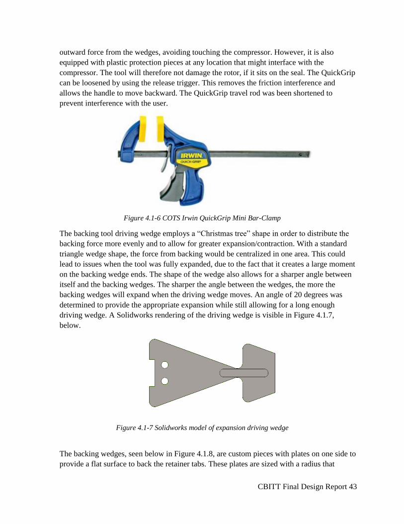
Figure 4.1-6 COTS Irwin QuickGrip Mini Bar-Clamp
The backing tool driving wedge employs a “Christmas tree” shape in order to distribute the
backing force more evenly and to allow for greater expansion/contraction. With a standard
triangle wedge shape, the force from backing would be centralized in one area. This could
lead to issues when the tool was fully expanded, due to the fact that it creates a large moment
on the backing wedge ends. The shape of the wedge also allows for a sharper angle between
itself and the backing wedges. The sharper the angle between the wedges, the more the
backing wedges will expand when the driving wedge moves. An angle of 20 degrees was
determined to provide the appropriate expansion while still allowing for a long enough
driving wedge. A Solidworks rendering of the driving wedge is visible in Figure 4.1.7,
below.
Figure 4.1-7 Solidworks model of expansion driving wedge
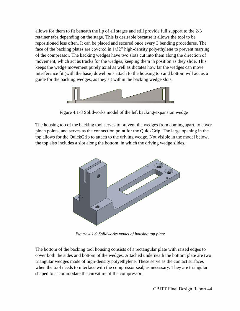
The backing wedges, seen below in Figure 4.1.8, are custom pieces with plates on one side to
provide a flat surface to back the retainer tabs. These plates are sized with a radius that
CBITT Final Design Report 44
allows for them to fit beneath the lip of all stages and still provide full support to the 2-3
retainer tabs depending on the stage. This is desirable because it allows the tool to be
repositioned less often. It can be placed and secured once every 3 bending procedures. The
face of the backing plates are covered in 1/32” high-density polyethylene to prevent marring
of the compressor. The backing wedges have two slots cut into them along the direction of
movement, which act as tracks for the wedges, keeping them in position as they slide. This
keeps the wedge movement purely axial as well as dictates how far the wedges can move.
Interference fit (with the base) dowel pins attach to the housing top and bottom will act as a
guide for the backing wedges, as they sit within the backing wedge slots.
Figure 4.1-8 Solidworks model of the left backing/expansion wedge
The housing top of the backing tool serves to prevent the wedges from coming apart, to cover
pinch points, and serves as the connection point for the QuickGrip. The large opening in the
top allows for the QuickGrip to attach to the driving wedge. Not visible in the model below,
the top also includes a slot along the bottom, in which the driving wedge slides.
Figure 4.1-9 Solidworks model of housing top plate
The bottom of the backing tool housing consists of a rectangular plate with raised edges to
cover both the sides and bottom of the wedges. Attached underneath the bottom plate are two
triangular wedges made of high-density polyethylene. These serve as the contact surfaces
when the tool needs to interface with the compressor seal, as necessary. They are triangular
shaped to accommodate the curvature of the compressor.
CBITT Final Design Report 45
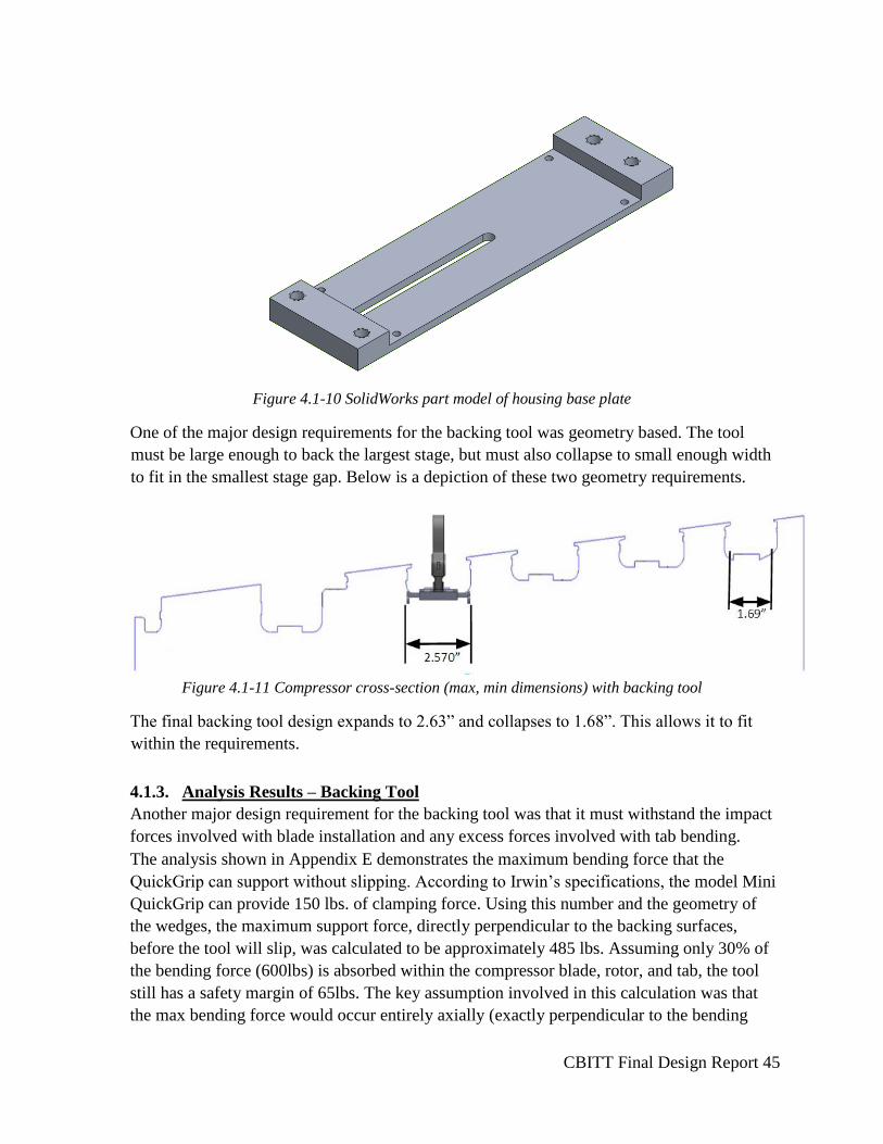
Figure 4.1-10 SolidWorks part model of housing base plate
One of the major design requirements for the backing tool was geometry based. The tool
must be large enough to back the largest stage, but must also collapse to small enough width
to fit in the smallest stage gap. Below is a depiction of these two geometry requirements.
Figure 4.1-11 Compressor cross-section (max, min dimensions) with backing tool
The final backing tool design expands to 2.63” and collapses to 1.68”. This allows it to fit
within the requirements.
4.1.3. Analysis Results – Backing Tool
Another major design requirement for the backing tool was that it must withstand the impact
forces involved with blade installation and any excess forces involved with tab bending.
The analysis shown in Appendix E demonstrates the maximum bending force that the
QuickGrip can support without slipping. According to Irwin’s specifications, the model Mini
QuickGrip can provide 150 lbs. of clamping force. Using this number and the geometry of
the wedges, the maximum support force, directly perpendicular to the backing surfaces,
before the tool will slip, was calculated to be approximately 485 lbs. Assuming only 30% of
the bending force (600lbs) is absorbed within the compressor blade, rotor, and tab, the tool
still has a safety margin of 65lbs. The key assumption involved in this calculation was that
the max bending force would occur entirely axially (exactly perpendicular to the bending

CBITT Final Design Report 46
tool), this assumption is very conservative. When the max bending force occurs the tab will
be at an intermediate angle so much of the force will not be directed into the backing tool.
The QuickGrip is also able to support more than 150 lbs. since the force it can support is
more than the force it can provide. With these considerations in mind, the QuickGrip is not
be in any danger of slipping during use.
Also shown in Appendix E is the bending moment and related stress calculations for the
backing wedges due to the bending force. The bending support force of 485 lbs. was used
and applied on the very tip of the backing wedge. The stress was then calculated at the two
points most likely to have a maximum stress and then compared to the yielding stress of 1215
steel. The lowest safety factor (S.F.=2.6) occurred at the thinnest part of the wedge, right
before the 20 degree angle change. Due to the very gradual angle change, a negligible stress
concentration was assumed. The application of the force at the very end is a worst case
scenario because if the backer is set up properly a tab should never be that far along the
backing wedge. Once again it was also assumed that the maximum bending force was the one
measured during testing and was entirely axial. From this analysis it can be concluded that
the backing wedge is not in danger of stress failure due to the bending moment.
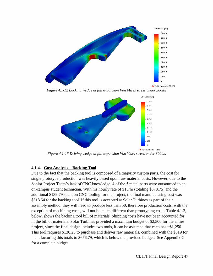
Finally finite element analysis (FEA) was conducted on the most critical components of the
backing tool design. The results can be seen in Figure 4.1.12 and 4.1.13 below. The FEA
shows that all stresses are below yield. The 485lb load was chosen because it is the point at
which the QuickGrip will slip. The tool should not be stressed beyond this point during use.
CBITT Final Design Report 47
Figure 4.1-12 Backing wedge at full expansion Von Mises stress under 300lbs
Figure 4.1-13 Driving wedge at full expansion Von Vises stress under 300lbs
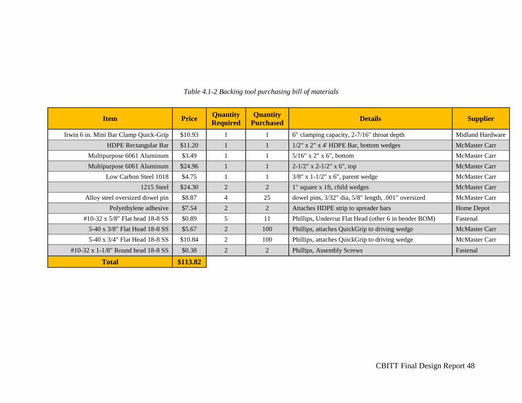
4.1.4. Cost Analysis – Backing Tool
Due to the fact that the backing tool is composed of a majority custom parts, the cost for
single prototype production was heavily based upon raw material costs. However, due to the
Senior Project Team’s lack of CNC knowledge, 4 of the 5 metal parts were outsourced to an
on-campus student technician. With his hourly rate of $15/hr (totaling $378.75) and the
additional $139.79 spent on CNC tooling for the project, the final manufacturing cost was
$518.54 for the backing tool. If this tool is accepted at Solar Turbines as part of their
assembly method, they will need to produce less than 50, therefore production costs, with the
exception of machining costs, will not be much different than prototyping costs. Table 4.1.2,
below, shows the backing tool bill of materials. Shipping costs have not been accounted for
in the bill of materials. Solar Turbines provided a maximum budget of $2,500 for the entire
project, since the final design includes two tools, it can be assumed that each has ~$1,250.
This tool requires $138.25 to purchase and deliver raw materials, combined with the $519 for
manufacturing this totals to $656.79, which is below the provided budget. See Appendix G
for a complete budget.
CBITT Final Design Report 48
Table 4.1-2 Backing tool purchasing bill of materials
Item Price Quantity
Required
Quantity
Purchased Details Supplier
Irwin 6 in. Mini Bar Clamp Quick-Grip $10.93 1 1 6" clamping capacity, 2-7/16" throat depth Midland Hardware
HDPE Rectangular Bar $11.20 1 1 1/2" x 2" x 4' HDPE Bar, bottom wedges McMaster Carr
Multipurpose 6061 Aluminum $3.49 1 1 5/16" x 2" x 6", bottom McMaster Carr
Multipurpose 6061 Aluminum $24.96 1 1 2-1/2" x 2-1/2" x 6", top McMaster Carr
Low Carbon Steel 1018 $4.75 1 1 3/8" x 1-1/2" x 6", parent wedge McMaster Carr
1215 Steel $24.30 2 2 1" square x 1ft, child wedges McMaster Carr
Alloy steel oversized dowel pin $8.87 4 25 dowel pins, 3/32" dia, 5/8" length, .001" oversized McMaster Carr
Polyethylene adhesive $7.54 2 2 Attaches HDPE strip to spreader bars Home Depot
#10-32 x 5/8" Flat head 18-8 SS $0.89 5 11 Phillips, Undercut Flat Head (other 6 in bender BOM) Fastenal
5-40 x 3/8" Flat Head 18-8 SS $5.67 2 100 Phillips, attaches QuickGrip to driving wedge McMaster Carr
5-40 x 3/4" Flat Head 18-8 SS $10.84 2 100 Phillips, attaches QuickGrip to driving wedge McMaster Carr
#10-32 x 1-1/8" Round head 18-8 SS $0.38 2 2 Phillips, Assembly Screws Fastenal
Total $113.82
CBITT Final Design Report 49
4.1.5. Material Selection – Backing Tool
Most of the force experienced by the backing tool is supported within the QuickGrip so
therefore, the material selection was not dependent, primarily, on strength. The primary
concern when choosing materials was avoiding having two components of the same material
moving against each other to avoid binding. The top and bottom are made of Multipurpose
6061 Aluminum because they require the largest stock and aluminum is relatively
inexpensive. The driving wedge and backing wedges are made of 1018 Carbon Steel and
1215 Steel respectively. These material choices allow for all moving parts to be made of
different materials. Metal was chosen to minimize compression of the system under load.
The plastic triangular wedges and plate lining were chosen to be made of high-density
polyethylene to provide contact surfaces that will not damage the compressor. HDPE was
used instead of Teflon because it is easier to find an adhesive that works with it and because
it is cheaper.
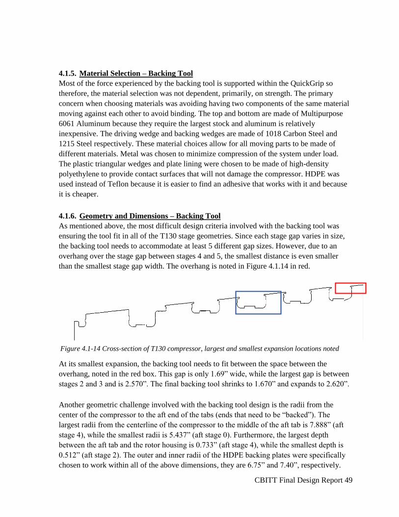
4.1.6. Geometry and Dimensions – Backing Tool
As mentioned above, the most difficult design criteria involved with the backing tool was
ensuring the tool fit in all of the T130 stage geometries. Since each stage gap varies in size,
the backing tool needs to accommodate at least 5 different gap sizes. However, due to an
overhang over the stage gap between stages 4 and 5, the smallest distance is even smaller
than the smallest stage gap width. The overhang is noted in Figure 4.1.14 in red.
Figure 4.1-14 Cross-section of T130 compressor, largest and smallest expansion locations noted
At its smallest expansion, the backing tool needs to fit between the space between the
overhang, noted in the red box. This gap is only 1.69” wide, while the largest gap is between
stages 2 and 3 and is 2.570”. The final backing tool shrinks to 1.670” and expands to 2.620”.
Another geometric challenge involved with the backing tool design is the radii from the
center of the compressor to the aft end of the tabs (ends that need to be “backed”). The
largest radii from the centerline of the compressor to the middle of the aft tab is 7.888” (aft
stage 4), while the smallest radii is 5.437” (aft stage 0). Furthermore, the largest depth
between the aft tab and the rotor housing is 0.733” (aft stage 4), while the smallest depth is
0.512” (aft stage 2). The outer and inner radii of the HDPE backing plates were specifically
chosen to work within all of the above dimensions, they are 6.75” and 7.40”, respectively.
CBITT Final Design Report 50
The backing tool length was sized such that it could accommodate multiple retainer tabs. The
overall length is 5.00”, allowing for at least three retainer tabs to be supported at once.
The height of the tower on the housing top came from the length of the jaws of the
QuickGrip. Lowering the height would have required designing custom jaws for the
QuickGrip which would have been significantly less cost and time efficient.
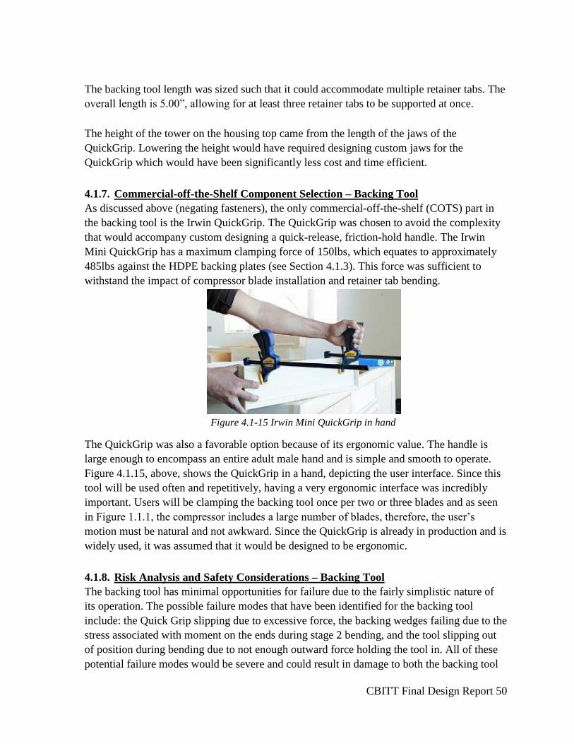
4.1.7. Commercial-off-the-Shelf Component Selection – Backing Tool
As discussed above (negating fasteners), the only commercial-off-the-shelf (COTS) part in
the backing tool is the Irwin QuickGrip. The QuickGrip was chosen to avoid the complexity
that would accompany custom designing a quick-release, friction-hold handle. The Irwin
Mini QuickGrip has a maximum clamping force of 150lbs, which equates to approximately
485lbs against the HDPE backing plates (see Section 4.1.3). This force was sufficient to
withstand the impact of compressor blade installation and retainer tab bending.
Figure 4.1-15 Irwin Mini QuickGrip in hand
The QuickGrip was also a favorable option because of its ergonomic value. The handle is
large enough to encompass an entire adult male hand and is simple and smooth to operate.
Figure 4.1.15, above, shows the QuickGrip in a hand, depicting the user interface. Since this
tool will be used often and repetitively, having a very ergonomic interface was incredibly
important. Users will be clamping the backing tool once per two or three blades and as seen
in Figure 1.1.1, the compressor includes a large number of blades, therefore, the user’s
motion must be natural and not awkward. Since the QuickGrip is already in production and is
widely used, it was assumed that it would be designed to be ergonomic.
4.1.8. Risk Analysis and Safety Considerations – Backing Tool
The backing tool has minimal opportunities for failure due to the fairly simplistic nature of
its operation. The possible failure modes that have been identified for the backing tool
include: the Quick Grip slipping due to excessive force, the backing wedges failing due to the
stress associated with moment on the ends during stage 2 bending, and the tool slipping out
of position during bending due to not enough outward force holding the tool in. All of these
potential failure modes would be severe and could result in damage to both the backing tool
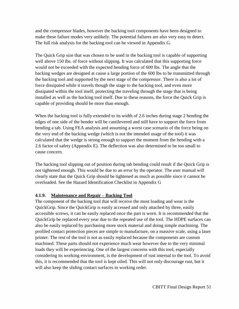
CBITT Final Design Report 51
and the compressor blades, however the backing tool components have been designed to
make these failure modes very unlikely. The potential failures are also very easy to detect.
The full risk analysis for the backing tool can be viewed in Appendix G.
The Quick Grip size that was chosen to be used in the backing tool is capable of supporting
well above 150 lbs. of force without slipping. It was calculated that this supporting force
would not be exceeded with the expected bending force of 600 lbs. The angle that the
backing wedges are designed at cause a large portion of the 600 lbs to be transmitted through
the backing tool and supported by the next stage of the compressor. There is also a lot of
force dissipated while it travels though the stage to the backing tool, and even more
dissipated within the tool itself, protecting the traveling through the stage that is being
installed as well as the backing tool itself. Due to these reasons, the force the Quick Grip is
capable of providing should be more than enough.
When the backing tool is fully extended to its width of 2.6 inches during stage 2 bending the
edges of one side of the bender will be cantilevered and still have to support the force from
bending a tab. Using FEA analysis and assuming a worst case scenario of the force being on
the very end of the backing wedge (which is not the intended usage of the tool) it was
calculated that the wedge is strong enough to support the moment from the bending with a
2.6 factor of safety (Appendix E). The deflection was also determined to be too small to
cause concern.
The backing tool slipping out of position during tab bending could result if the Quick Grip is
not tightened enough. This would be due to an error by the operator. The user manual will
clearly state that the Quick Grip should be tightened as much as possible since it cannot be
overloaded. See the Hazard Identification Checklist in Appendix G
4.1.9. Maintenance and Repair – Backing Tool
The component of the backing tool that will receive the most loading and wear is the
QuickGrip. Since the QuickGrip is easily accessed and only attached by three, easily
accessible screws, it can be easily replaced once the part is worn. It is recommended that the
QuickGrip be replaced every year due to the repeated use of the tool. The HDPE surfaces can
also be easily replaced by purchasing more stock material and doing simple machining. The
profiled contact protection pieces are simple to manufacture, on a massive scale, using a laser
printer. The rest of the tool is not as easily replaced because the components are custom
machined. These parts should not experience much wear however due to the very minimal
loads they will be experiencing. One of the largest concerns with this tool, especially
considering its working environment, is the development of rust internal to the tool. To avoid
this, it is recommended that the tool is kept oiled. This will not only discourage rust, but it
will also keep the sliding contact surfaces in working order.
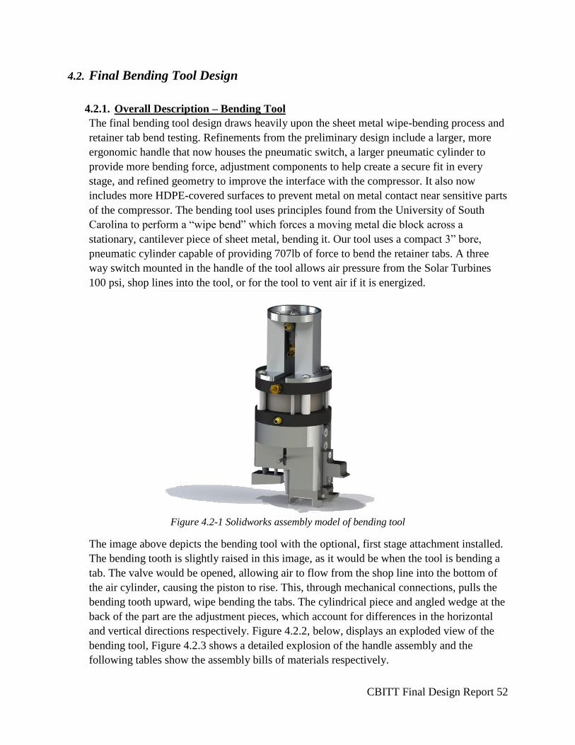
CBITT Final Design Report 52
4.2. Final Bending Tool Design
4.2.1. Overall Description – Bending Tool
The final bending tool design draws heavily upon the sheet metal wipe-bending process and
retainer tab bend testing. Refinements from the preliminary design include a larger, more
ergonomic handle that now houses the pneumatic switch, a larger pneumatic cylinder to
provide more bending force, adjustment components to help create a secure fit in every
stage, and refined geometry to improve the interface with the compressor. It also now
includes more HDPE-covered surfaces to prevent metal on metal contact near sensitive parts
of the compressor. The bending tool uses principles found from the University of South
Carolina to perform a “wipe bend” which forces a moving metal die block across a
stationary, cantilever piece of sheet metal, bending it. Our tool uses a compact 3” bore,
pneumatic cylinder capable of providing 707lb of force to bend the retainer tabs. A three
way switch mounted in the handle of the tool allows air pressure from the Solar Turbines
100 psi, shop lines into the tool, or for the tool to vent air if it is energized.
Figure 4.2-1 Solidworks assembly model of bending tool
The image above depicts the bending tool with the optional, first stage attachment installed.
The bending tooth is slightly raised in this image, as it would be when the tool is bending a
tab. The valve would be opened, allowing air to flow from the shop line into the bottom of
the air cylinder, causing the piston to rise. This, through mechanical connections, pulls the
bending tooth upward, wipe bending the tabs. The cylindrical piece and angled wedge at the
back of the part are the adjustment pieces, which account for differences in the horizontal
and vertical directions respectively. Figure 4.2.2, below, displays an exploded view of the
bending tool, Figure 4.2.3 shows a detailed explosion of the handle assembly and the
following tables show the assembly bills of materials respectively.
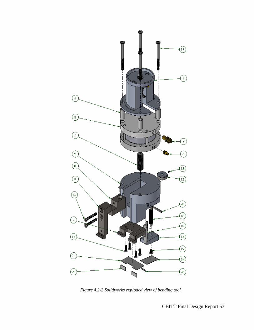
CBITT Final Design Report 53
Figure 4.2-2 Solidworks exploded view of bending tool
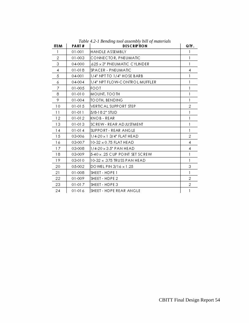
CBITT Final Design Report 54
Table 4.2-1 Bending tool assembly bill of materials
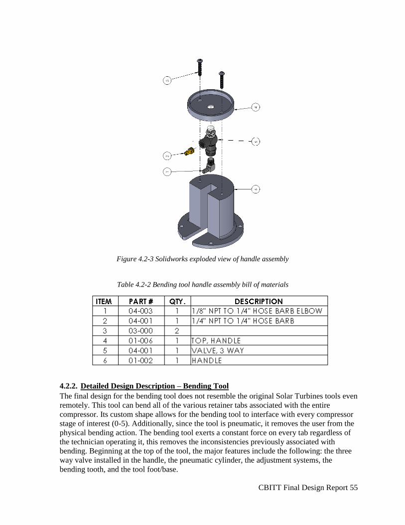
CBITT Final Design Report 55
Figure 4.2-3 Solidworks exploded view of handle assembly
Table 4.2-2 Bending tool handle assembly bill of materials
4.2.2. Detailed Design Description – Bending Tool
The final design for the bending tool does not resemble the original Solar Turbines tools even
remotely. This tool can bend all of the various retainer tabs associated with the entire
compressor. Its custom shape allows for the bending tool to interface with every compressor
stage of interest (0-5). Additionally, since the tool is pneumatic, it removes the user from the
physical bending action. The bending tool exerts a constant force on every tab regardless of
the technician operating it, this removes the inconsistencies previously associated with
bending. Beginning at the top of the tool, the major features include the following: the three
way valve installed in the handle, the pneumatic cylinder, the adjustment systems, the
bending tooth, and the tool foot/base.
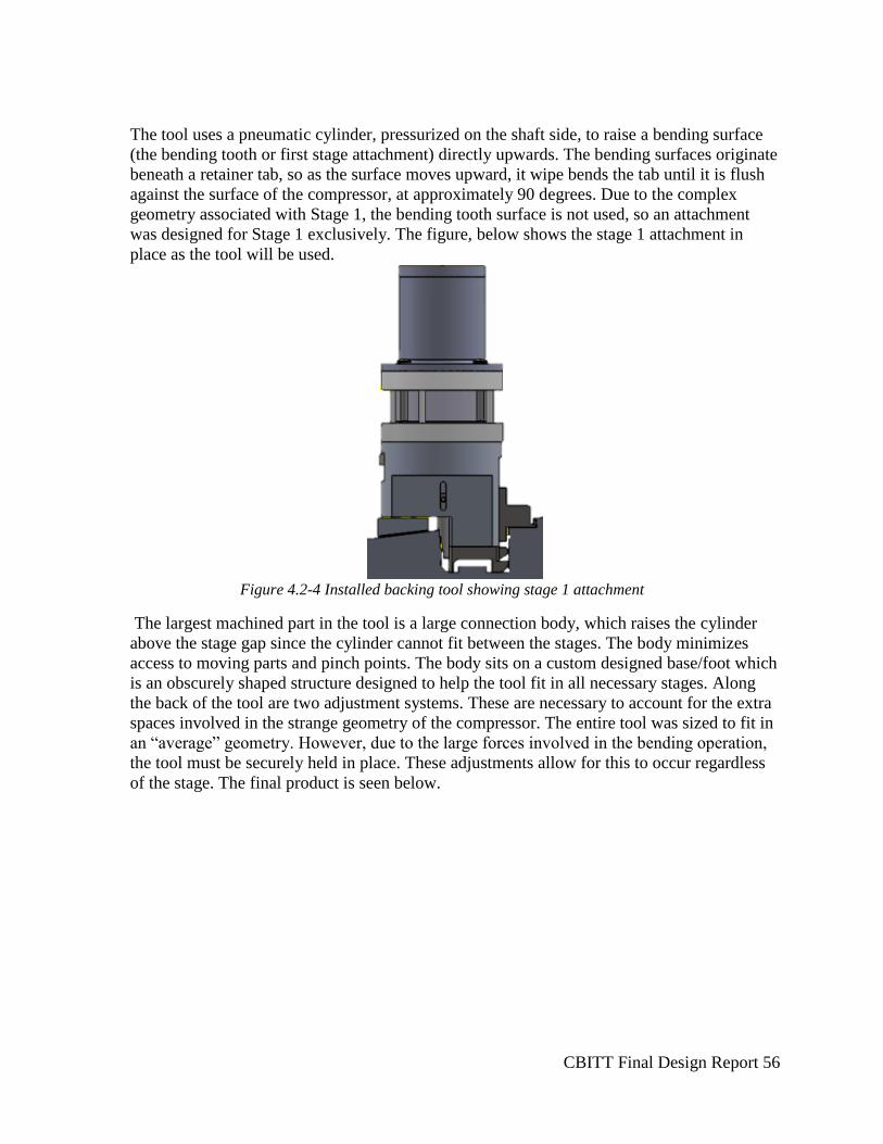
CBITT Final Design Report 56
The tool uses a pneumatic cylinder, pressurized on the shaft side, to raise a bending surface
(the bending tooth or first stage attachment) directly upwards. The bending surfaces originate
beneath a retainer tab, so as the surface moves upward, it wipe bends the tab until it is flush
against the surface of the compressor, at approximately 90 degrees. Due to the complex
geometry associated with Stage 1, the bending tooth surface is not used, so an attachment
was designed for Stage 1 exclusively. The figure, below shows the stage 1 attachment in
place as the tool will be used.
Figure 4.2-4 Installed backing tool showing stage 1 attachment
The largest machined part in the tool is a large connection body, which raises the cylinder
above the stage gap since the cylinder cannot fit between the stages. The body minimizes
access to moving parts and pinch points. The body sits on a custom designed base/foot which
is an obscurely shaped structure designed to help the tool fit in all necessary stages. Along
the back of the tool are two adjustment systems. These are necessary to account for the extra
spaces involved in the strange geometry of the compressor. The entire tool was sized to fit in
an “average” geometry. However, due to the large forces involved in the bending operation,
the tool must be securely held in place. These adjustments allow for this to occur regardless
of the stage. The final product is seen below.
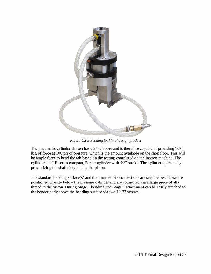
CBITT Final Design Report 57
Figure 4.2-5 Bending tool final design product
The pneumatic cylinder chosen has a 3 inch bore and is therefore capable of providing 707
lbs. of force at 100 psi of pressure, which is the amount available on the shop floor. This will
be ample force to bend the tab based on the testing completed on the Instron machine. The
cylinder is a LP-series compact, Parker cylinder with 5/8” stroke. The cylinder operates by
pressurizing the shaft side, raising the piston.
The standard bending surface(s) and their immediate connections are seen below. These are
positioned directly below the pressure cylinder and are connected via a large piece of all-
thread to the piston. During Stage 1 bending, the Stage 1 attachment can be easily attached to
the bender body above the bending surface via two 10-32 screws.
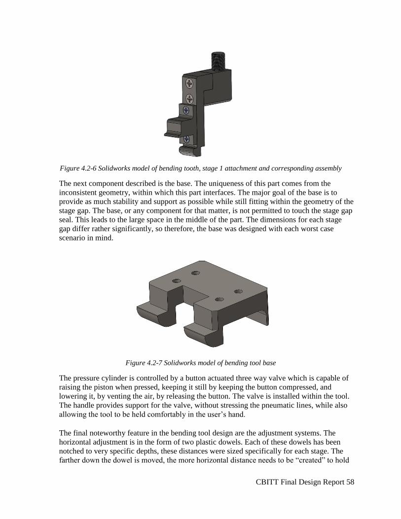
CBITT Final Design Report 58
Figure 4.2-6 Solidworks model of bending tooth, stage 1 attachment and corresponding assembly
The next component described is the base. The uniqueness of this part comes from the
inconsistent geometry, within which this part interfaces. The major goal of the base is to
provide as much stability and support as possible while still fitting within the geometry of the
stage gap. The base, or any component for that matter, is not permitted to touch the stage gap
seal. This leads to the large space in the middle of the part. The dimensions for each stage
gap differ rather significantly, so therefore, the base was designed with each worst case
scenario in mind.
Figure 4.2-7 Solidworks model of bending tool base
The pressure cylinder is controlled by a button actuated three way valve which is capable of
raising the piston when pressed, keeping it still by keeping the button compressed, and
lowering it, by venting the air, by releasing the button. The valve is installed within the tool.
The handle provides support for the valve, without stressing the pneumatic lines, while also
allowing the tool to be held comfortably in the user’s hand.
The final noteworthy feature in the bending tool design are the adjustment systems. The
horizontal adjustment is in the form of two plastic dowels. Each of these dowels has been
notched to very specific depths, these distances were sized specifically for each stage. The
farther down the dowel is moved, the more horizontal distance needs to be “created” to hold
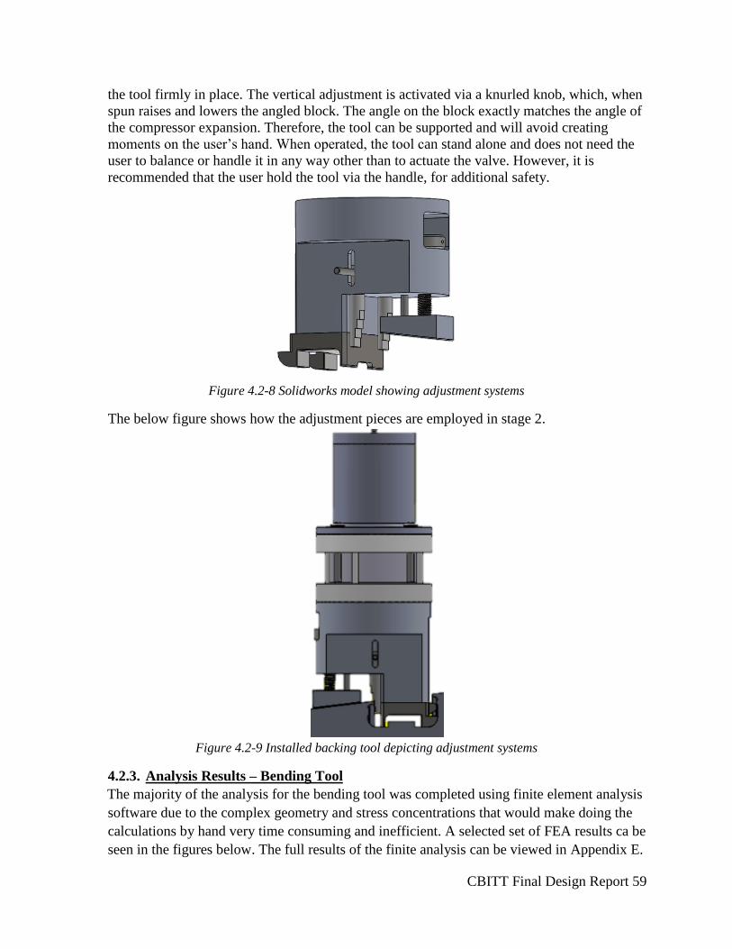
CBITT Final Design Report 59
the tool firmly in place. The vertical adjustment is activated via a knurled knob, which, when
spun raises and lowers the angled block. The angle on the block exactly matches the angle of
the compressor expansion. Therefore, the tool can be supported and will avoid creating
moments on the user’s hand. When operated, the tool can stand alone and does not need the
user to balance or handle it in any way other than to actuate the valve. However, it is
recommended that the user hold the tool via the handle, for additional safety.
Figure 4.2-8 Solidworks model showing adjustment systems
The below figure shows how the adjustment pieces are employed in stage 2.
Figure 4.2-9 Installed backing tool depicting adjustment systems
4.2.3. Analysis Results – Bending Tool
The majority of the analysis for the bending tool was completed using finite element analysis
software due to the complex geometry and stress concentrations that would make doing the
calculations by hand very time consuming and inefficient. A selected set of FEA results ca be
seen in the figures below. The full results of the finite analysis can be viewed in Appendix E.
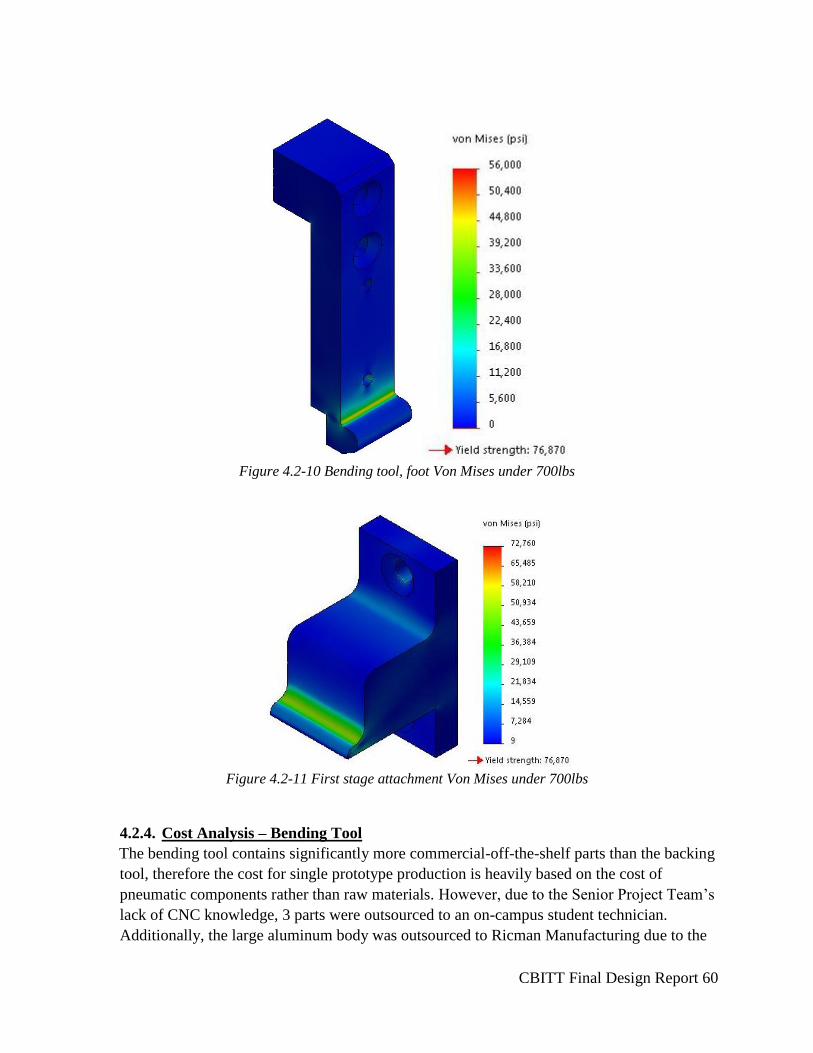
CBITT Final Design Report 60
Figure 4.2-10 Bending tool, foot Von Mises under 700lbs
Figure 4.2-11 First stage attachment Von Mises under 700lbs
4.2.4. Cost Analysis – Bending Tool
The bending tool contains significantly more commercial-off-the-shelf parts than the backing
tool, therefore the cost for single prototype production is heavily based on the cost of
pneumatic components rather than raw materials. However, due to the Senior Project Team’s
lack of CNC knowledge, 3 parts were outsourced to an on-campus student technician.
Additionally, the large aluminum body was outsourced to Ricman Manufacturing due to the

CBITT Final Design Report 61
complexity and need for tight tolerances. With the student technician hourly rate of $28/hr
(totaling $392.00), the additional $143.58 spent on CNC tooling for the project and the cost
of the professionally manufactured part, $724.95, the final manufacturing cost was $1260.53
for the bending tool. Table 4.2.2, below, shows the bending tool bill of materials. Shipping
costs have not been accounted for in the bill of materials. Solar Turbines provided a
maximum budget of $2,500 for the entire project, since the final design includes two tools, it
can be assumed that each has ~$1,250. This tool requires $692.79 to purchase and deliver
raw materials, added to the $1260 for manufacturing, the tool totals to $1,953.18, which is
slightly above budget. See Appendix G for a complete budget.
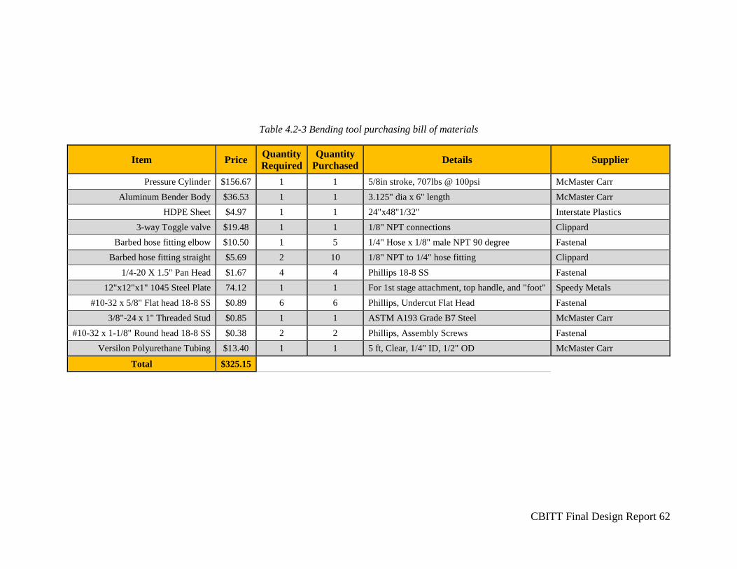
CBITT Final Design Report 62
Table 4.2-3 Bending tool purchasing bill of materials
Item Price Quantity
Required
Quantity
Purchased Details Supplier
Pressure Cylinder $156.67 1 1 5/8in stroke, 707lbs @ 100psi McMaster Carr
Aluminum Bender Body $36.53 1 1 3.125" dia x 6" length McMaster Carr
HDPE Sheet $4.97 1 1 24"x48"1/32" Interstate Plastics
3-way Toggle valve $19.48 1 1 1/8" NPT connections Clippard
Barbed hose fitting elbow $10.50 1 5 1/4" Hose x 1/8" male NPT 90 degree Fastenal
Barbed hose fitting straight $5.69 2 10 1/8" NPT to 1/4" hose fitting Clippard
1/4-20 X 1.5" Pan Head $1.67 4 4 Phillips 18-8 SS Fastenal
12"x12"x1" 1045 Steel Plate 74.12 1 1 For 1st stage attachment, top handle, and "foot" Speedy Metals
#10-32 x 5/8" Flat head 18-8 SS $0.89 6 6 Phillips, Undercut Flat Head Fastenal
3/8"-24 x 1" Threaded Stud $0.85 1 1 ASTM A193 Grade B7 Steel McMaster Carr
#10-32 x 1-1/8" Round head 18-8 SS $0.38 2 2 Phillips, Assembly Screws Fastenal
Versilon Polyurethane Tubing $13.40 1 1 5 ft, Clear, 1/4" ID, 1/2" OD McMaster Carr
Total $325.15
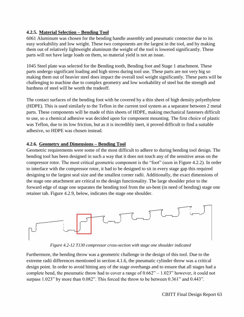
CBITT Final Design Report 63
4.2.5. Material Selection – Bending Tool
6061 Aluminum was chosen for the bending handle assembly and pneumatic connector due to its
easy workability and low weight. These two components are the largest in the tool, and by making
them out of relatively lightweight aluminum the weight of the tool is lowered significantly. These
parts will not have large loads on them, so material yield is not an issue.
1045 Steel plate was selected for the Bending tooth, Bending foot and Stage 1 attachment. These
parts undergo significant loading and high stress during tool use. These parts are not very big so
making them out of heavier steel does impact the overall tool weight significantly. These parts will be
challenging to machine due to complex geometry and low workability of steel but the strength and
hardness of steel will be worth the tradeoff.
The contact surfaces of the bending foot with be covered by a thin sheet of high density polyethylene
(HDPE). This is used similarly to the Teflon in the current tool system as a separator between 2 metal
parts. These components will be made of thin sheets of HDPE, making mechanical fasteners difficult
to use, so a chemical adhesive was decided upon for component mounting. The first choice of plastic
was Teflon, due to its low friction, but as it is incredibly inert, it proved difficult to find a suitable
adhesive, so HDPE was chosen instead.
4.2.6. Geometry and Dimensions – Bending Tool
Geometric requirements were some of the most difficult to adhere to during bending tool design. The
bending tool has been designed in such a way that it does not touch any of the sensitive areas on the
compressor rotor. The most critical geometric component is the “foot” (seen in Figure 4.2.2). In order
to interface with the compressor rotor, it had to be designed to sit in every stage gap this required
designing to the largest seal size and the smallest corner radii. Additionally, the exact dimensions of
the stage one attachment are critical to the design functionality. The large shoulder prior to the
forward edge of stage one separates the bending tool from the un-bent (in need of bending) stage one
retainer tab. Figure 4.2.9, below, indicates the stage one shoulder.
Figure 4.2-12 T130 compressor cross-section with stage one shoulder indicated
Furthermore, the bending throw was a geometric challenge in the design of this tool. Due to the
extreme radii differences mentioned in section 4.1.6, the pneumatic cylinder throw was a critical
design point. In order to avoid hitting any of the stage overhangs and to ensure that all stages had a
complete bend, the pneumatic throw had to cover a range of 0.662” – 1.023” however, it could not
surpass 1.023” by more than 0.082”. This forced the throw to be between 0.361” and 0.443”.
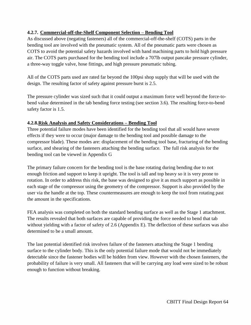
CBITT Final Design Report 64
4.2.7. Commercial-off-the-Shelf Component Selection – Bending Tool
As discussed above (negating fasteners) all of the commercial-off-the-shelf (COTS) parts in the
bending tool are involved with the pneumatic system. All of the pneumatic parts were chosen as
COTS to avoid the potential safety hazards involved with hand machining parts to hold high pressure
air. The COTS parts purchased for the bending tool include a 707lb output pancake pressure cylinder,
a three-way toggle valve, hose fittings, and high pressure pneumatic tubing.
All of the COTS parts used are rated far beyond the 100psi shop supply that will be used with the
design. The resulting factor of safety against pressure burst is 2.5.
The pressure cylinder was sized such that it could output a maximum force well beyond the force-to-
bend value determined in the tab bending force testing (see section 3.6). The resulting force-to-bend
safety factor is 1.5.
4.2.8.Risk Analysis and Safety Considerations – Bending Tool
Three potential failure modes have been identified for the bending tool that all would have severe
effects if they were to occur (major damage to the bending tool and possible damage to the
compressor blade). These modes are: displacement of the bending tool base, fracturing of the bending
surface, and shearing of the fasteners attaching the bending surface. The full risk analysis for the
bending tool can be viewed in Appendix G
The primary failure concern for the bending tool is the base rotating during bending due to not
enough friction and support to keep it upright. The tool is tall and top heavy so it is very prone to
rotation. In order to address this risk, the base was designed to give it as much support as possible in
each stage of the compressor using the geometry of the compressor. Support is also provided by the
user via the handle at the top. These countermeasures are enough to keep the tool from rotating past
the amount in the specifications.
FEA analysis was completed on both the standard bending surface as well as the Stage 1 attachment.
The results revealed that both surfaces are capable of providing the force needed to bend that tab
without yielding with a factor of safety of 2.6 (Appendix E). The deflection of these surfaces was also
determined to be a small amount.
The last potential identified risk involves failure of the fasteners attaching the Stage 1 bending
surface to the cylinder body. This is the only potential failure mode that would not be immediately
detectable since the fastener bodies will be hidden from view. However with the chosen fasteners, the
probability of failure is very small. All fasteners that will be carrying any load were sized to be robust
enough to function without breaking.

CBITT Final Design Report 65
4.2.9. Maintenance and Repair - Bending Tool
The components of the bending tool that will wear the most rapidly are the bending tooth and Stage 1
attachment. They are small surfaces that will be seeing repeated high loads so they will eventually
chip and fracture. These parts are very easily accessed and removed since they are located on the
outside of the bending tool and are only fastened by a couple screws. Making replacement bending
surfaces will require some CNC machining but would not be too difficult or time consuming with the
part drawings already on hand.
The cylinder can also be easily replaced after several years of use as it reaches its rated lifetime. All
that must be done is removing the fasteners on top and the threaded stud below. A replacement
cylinder can be purchased COTS from McMaster Carr at a reasonable cost for the length of time it
will last.
The other parts in the bending tool are not easily replaced due to either low accessibility or
difficulties in obtaining replacement parts. These parts should not experience much wear due to zero
or low loading on them.
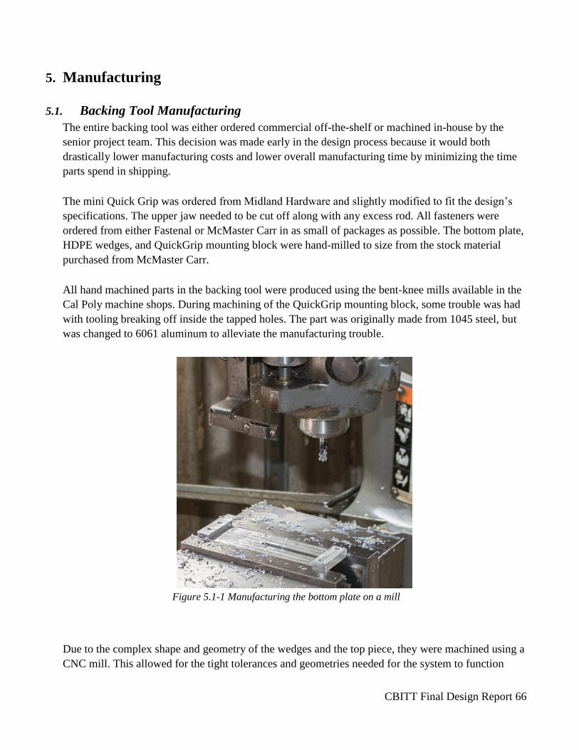
CBITT Final Design Report 66
5. Manufacturing
5.1. Backing Tool Manufacturing
The entire backing tool was either ordered commercial off-the-shelf or machined in-house by the
senior project team. This decision was made early in the design process because it would both
drastically lower manufacturing costs and lower overall manufacturing time by minimizing the time
parts spend in shipping.
The mini Quick Grip was ordered from Midland Hardware and slightly modified to fit the design’s
specifications. The upper jaw needed to be cut off along with any excess rod. All fasteners were
ordered from either Fastenal or McMaster Carr in as small of packages as possible. The bottom plate,
HDPE wedges, and QuickGrip mounting block were hand-milled to size from the stock material
purchased from McMaster Carr.
All hand machined parts in the backing tool were produced using the bent-knee mills available in the
Cal Poly machine shops. During machining of the QuickGrip mounting block, some trouble was had
with tooling breaking off inside the tapped holes. The part was originally made from 1045 steel, but
was changed to 6061 aluminum to alleviate the manufacturing trouble.
Figure 5.1-1 Manufacturing the bottom plate on a mill
Due to the complex shape and geometry of the wedges and the top piece, they were machined using a
CNC mill. This allowed for the tight tolerances and geometries needed for the system to function
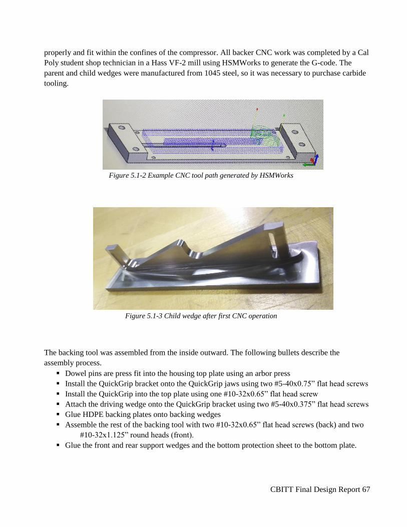
CBITT Final Design Report 67
properly and fit within the confines of the compressor. All backer CNC work was completed by a Cal
Poly student shop technician in a Hass VF-2 mill using HSMWorks to generate the G-code. The
parent and child wedges were manufactured from 1045 steel, so it was necessary to purchase carbide
tooling.
Figure 5.1-2 Example CNC tool path generated by HSMWorks
Figure 5.1-3 Child wedge after first CNC operation
The backing tool was assembled from the inside outward. The following bullets describe the
assembly process.
Dowel pins are press fit into the housing top plate using an arbor press
Install the QuickGrip bracket onto the QuickGrip jaws using two #5-40x0.75” flat head screws
Install the QuickGrip into the top plate using one #10-32x0.65” flat head screw
Attach the driving wedge onto the QuickGrip bracket using two #5-40x0.375” flat head screws
Glue HDPE backing plates onto backing wedges
Assemble the rest of the backing tool with two #10-32x0.65” flat head screws (back) and two
#10-32x1.125” round heads (front).
Glue the front and rear support wedges and the bottom protection sheet to the bottom plate.
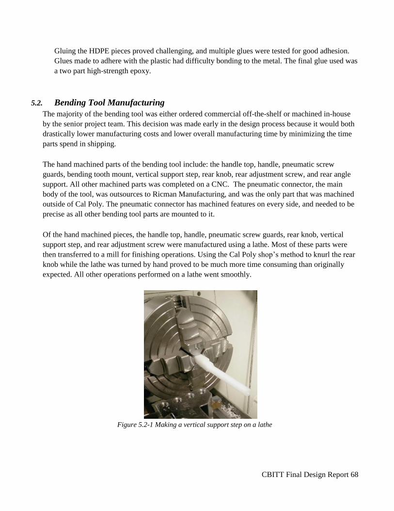
CBITT Final Design Report 68
Gluing the HDPE pieces proved challenging, and multiple glues were tested for good adhesion.
Glues made to adhere with the plastic had difficulty bonding to the metal. The final glue used was
a two part high-strength epoxy.
5.2. Bending Tool Manufacturing
The majority of the bending tool was either ordered commercial off-the-shelf or machined in-house
by the senior project team. This decision was made early in the design process because it would both
drastically lower manufacturing costs and lower overall manufacturing time by minimizing the time
parts spend in shipping.
The hand machined parts of the bending tool include: the handle top, handle, pneumatic screw
guards, bending tooth mount, vertical support step, rear knob, rear adjustment screw, and rear angle
support. All other machined parts was completed on a CNC. The pneumatic connector, the main
body of the tool, was outsources to Ricman Manufacturing, and was the only part that was machined
outside of Cal Poly. The pneumatic connector has machined features on every side, and needed to be
precise as all other bending tool parts are mounted to it.
Of the hand machined pieces, the handle top, handle, pneumatic screw guards, rear knob, vertical
support step, and rear adjustment screw were manufactured using a lathe. Most of these parts were
then transferred to a mill for finishing operations. Using the Cal Poly shop’s method to knurl the rear
knob while the lathe was turned by hand proved to be much more time consuming than originally
expected. All other operations performed on a lathe went smoothly.
Figure 5.2-1 Making a vertical support step on a lathe

CBITT Final Design Report 69
The foot, first stage attachment, and bending tooth were machined using a CNC mill by a Cal Poly
student shop technician in a Hass VF-3 mill using HSMWorks to generate the G-code. These parts
were made from 1045 steel, so it was necessary to purchase carbide tooling.
Two parts that changed significantly from their original designs were the handle and handle top.
Their diameter was originally set at 3 inches, however, during machining this was decided to be
much too large to comfortably hold. A final diameter of 2.25 inches was settled upon. All mounting
holes on the top of the handle were then adjusted inward to accommodate for this change.
The bending tool was assembled from the inside outward. The following bullets describe the
assembly process.
Assemble handle pneumatic components Teflon seal tape and attach to handle top
Thread hose barb and exhaust speed control into the pneumatic cylinder using Teflon seal tape
Attach assembly to handle using two #10-32x1.125” round head screws
Thread 5/8 -18 x 2” stud into pneumatic cylinder and bending tooth mount
Thread #5-40x0.25” cup point set screw partially into rear knob
Thread rear adjustment screw into pneumatic connector with end with a flat inside the pocket
in the connector
Place the rear knob on the rear adjustment screw and tighten the set screw onto the flat
Press 3/16x1.25” oversized dowel pin into the rear angle support using an arbor press
Attach the rear angle support to the rear adjustment screw using a #10-32x0.375” truss pan
head screw
Place two vertical support steps into pneumatic connector and gently press fit 3/16x1.25”
oversize dowel pins into vertical support step
Place screw guards in the in the pneumatic gaps and assemble the handle, cylinder, and
pneumatic connector using 4 ¼-20x3.5” pan head screws.
Attach bending tooth to bending tooth mount using 1/4 -20x1.625” flat head screws
Attach foot to pneumatic connector using four #10-32x0.75” flat head screws
Glue HDPE plates to rear angle support and foot
Attach pneumatic tubing between cylinder and handle assembly
Connect first stage attachment to the bending tooth as needed
In future manufacturing of this tool, the price of CNC work must be accounted for. An unexpected
related expense was that students must purchase their own tooling when a Cal Poly shop technician does
CNC manufacturing. The price of tooling combined with the cost of labor cost more than twice that of
the material and work for the rest of the bending tool.
6. Design Verification/Testing

CBITT Final Design Report 70
Due to the nature of this project, testing was not able to be completed on campus, excluding the tab
bend testing. All of the design verification involved with the tooling requires a compressor rotor.
While the team was able to 3-D print a representative compressor in order to confirm dimensions and
fit, functionality tests were not possible until delivering the design to Solar Turbines. This delivery
will occur after this report has been submitted and therefore the results will not be included.
The testing and verification that has been completed thus far has been mostly related to the proper
critical dimensions of the tools. It is paramount that the tools have been machined precisely to
specification in order to ensure that the tool will fit in the tight constraints of the compressor. To
verify these dimensions, the team measured each critical dimension was measured with high
precision digital calipers. The major dimensions that were measured on the backing tool were the
minimum width when the tool was fully contracted and the maximum width when the tool was fully
expanded. It was verified that the back was successful in contracting to the design width of 1.68
inches and expanding to the design width of 2.63 inches, and therefore is capable of backing tabs
across all five stages that the project was concerned with. The major measurements necessary for the
bending tool was ensuring that the lower half would properly fit in between the compressor stages
and that the upper half would not contact any blades. It was verified that the tool is to tolerance and
fits easily in all compressor gaps, as well as that the body will not contact any installed blades. One
other form of testing that has been completed for the bending tool is verification that the pneumatic
cylinder is capable of moving the bending surface the necessary 0.63 inches. To test this, the team
attached the bending tool to pressure lines located in the Mustang 60 machine shop. It was found that
the tool was capable of moving the entire design throw after pressing the button when pressurized.
Due to the complex geometry and large forces associated with testing the bending tool, it is very
difficult and impractical to attempt to test the tool’s ability to bend tabs at school. Therefore, the
major product testing involving the bending and backing of tabs will take place on Friday, June 3rd at
the Solar Turbines office in San Diego. The team will travel down with the tools and complete a
number of tests in the actual environment that they will actually be used in. This will verify that the
tools are capable of completing their design function to both the senior project team as well as the
sponsors.
The first major test that will be completed is putting each of the tools in place in all five stages of the
compressor. The bending tool will pass if it can fit in each necessary stage gap and the backing tool
will pass if it is capable of holding itself up in each stage gap.
The second test will be to verify the functionality of the backing tool. A compressor blade will be
placed in its slot with a retainer tab beneath it. The backer will then be put in place and expanded to
the necessary width to apply pressure to the tab. A technician will then complete a standard full bend
of the other side of the retainer tab using the bending method that is currently used. If the tool is able
to remain in position without falling, shifting, or contracting during the duration of the bending
process, it passes the test. This test will then be completed with three blades in place to ensure that
the tool can simultaneously back three tabs at once. If possible, the test will be completed a number
of times to prove consistency.
CBITT Final Design Report 71
The final test will be using both tools to complete a bend of a retainer tab. Like previously, the blade
will be placed in the slot on top of a retainer tab, and then the backing tool will be expanded in its
place. Then this time the bending tool will be attached to a shop pressure line and then slid in place
under the tab. The technician will then actuate the device and complete a bend on the tab. Both tools
will be verified if the tab is bent, they remain in place over the whole process, and no severe contact
with the compressor occurs. It is acceptable if a small final blow with a hammer is necessary at the
end to make the bend a full 90 degrees. The test should be repeated several times to guarantee
consistency, and each trial should be timed to prove that the new bending process is much less time-
consuming than the current one.
Due to the fact that the main portion of the testing has not yet been completed, detailed results are not
yet available. Once testing has been completed, detailed results such as videos and a fully completed
DVPR will be made available to Solar Turbines. The current verification plans and results can be
viewed below in Appendix G.
7. Conclusions and Recommendations The backing and bending tools described in this report have been designed such that they will fulfill their
task in every stage of the Titan 130 turbine, eliminating the current need for numerous tools. The reduced
number of tools, along with the greater precision provided by the new tools will allow for faster blade
installation times with fewer mistakes. This tool has numerous advantages over the system it sought to
improve upon. Greatest of these is the ability to create consistent, controllable tab bends. The installation
process can now be held to appropriate standards, additionally, immense time and money will be saved
by not only reducing man hours, but also reducing the number of damaged rotors and blades during
installation.
The relative success of this project can be attributed to many factors, however, the greatest advantage
present when creating these tools was the ability to confirm all geometry changes in Solidworks. Early in
the project, the team built a representation of the compressor rotor in Solidworks, against which they
compared all tooling design changes. The painstakingly iterative process to find the perfect “geometric
middle ground” for both tools would not have been successful without the compressor representation.
Furthermore, the team’s dedication to keep their tooling as simple as possible, shying from unnecessary
complication and keeping the tooling completely mechanical was extremely helpful in trouble shooting.
Furthermore, prior to beginning manufacturing, the team developed assembly plans to ensure all
components could not only be machined, but could also be assembled. An additional advantage was the
magnitude of the budget for this project. Having the freedom to outsource difficult machining made the
manufacturing phase immensely less complicated. However, while the project had relative success and
the team is confident in their design, there are many areas where the tools could be improved and the
entire project process could have been improved as well.
CBITT Final Design Report 72
7.1. Recommendations
7.1.1. Further Design Recommendations
Of all of the possible design improvements that could be introduced to this tool, one of the
simplest and most beneficial would be the addition of a spring back system on the backing tool.
With the current design, the return movement of the tool is sloppy and if not done correctly can
lead to the tool binding. On the bending tool, the greatest design improvement would be to make
the tool lighter. It is currently almost 11lbs and is therefore slightly cumbersome to handle. In
general, all of the steel components should have been coated to avoid rusting problems. Finally,
the plastic protection pieces, while serve their purpose were very difficult to glue to the metal
surfaces and other cushioning possibilities should be considered.
7.1.2. General Senior Project Recommendations
Throughout this project, the team overcame numerous challenges, however, a majority of these
could have been avoided if they had known to “look out” for them. During the first quarter, the
team did not establish a consistent meeting time with their sponsor which lead to
miscommunications. Therefore it is recommended that sponsor meetings are held once per two
weeks in the first quarter and possible once per week in the second and third quarters. The second
quarter, design quarter, went relatively smoothly. The team spent countless hours comparing
Solidworks assemblies to ensure fits and placement. However, the team did not appropriately
consider tolerances and the difficult the keep tight tolerances as inexperienced machinists. The
majority of difficulties arose in the final phase of the project, build and test. Firstly, the team did
not begin manufacturing until the 3rd week of the quarter which lead to rushed work and some
poorly made pieces. They also did not order enough raw material to account for imperfect parts.
Therefore if a part was not made correctly, it had to be “improved” or “saved” because there was
not enough material to make another. Additionally, when receiving orders, often parts were lost
or misplaced. Furthermore, the team did not seek outsourced assistance for machining until later
in the quarter and if it were not for personal connections may not have completed all of their CNC
parts in time. Finally, the team did not plan for testing. While they had planned to complete
testing on site, they did not plan for data measurement or component rigging.
CBITT Final Design Report 73
Appendices Table of Contents
A1. House of Quality ...................................................................................................................... 74
A2. Morphological Matrix .............................................................................................................. 75
A3. Design Matrix .......................................................................................................................... 76
B1. Structured BOM ....................................................................................................................... 78
B2. Part and Assembly Drawings ................................................................................................... 80
C1. List of Vendors ....................................................................................................................... 109
D1. Vendor Data Sheets ................................................................................................................ 110
E1. Preliminary Wipe Bending Calculations ................................................................................ 132
E2. Finite Element Analysis ......................................................................................................... 133
F1. Gantt Chart .............................................................................................................................. 136
G1. Vocabulary and Acronyms ..................................................................................................... 137
G2. Hazard Identification Checklist ............................................................................................. 138
G3. Tab Bending Test Results ...................................................................................................... 140
G4. Risk Analysis ......................................................................................................................... 144
G5. Testing Plans .......................................................................................................................... 145
G6. Statement of Work ................................................................................................................. 146
G7. Itemized Budget ..................................................................................................................... 149
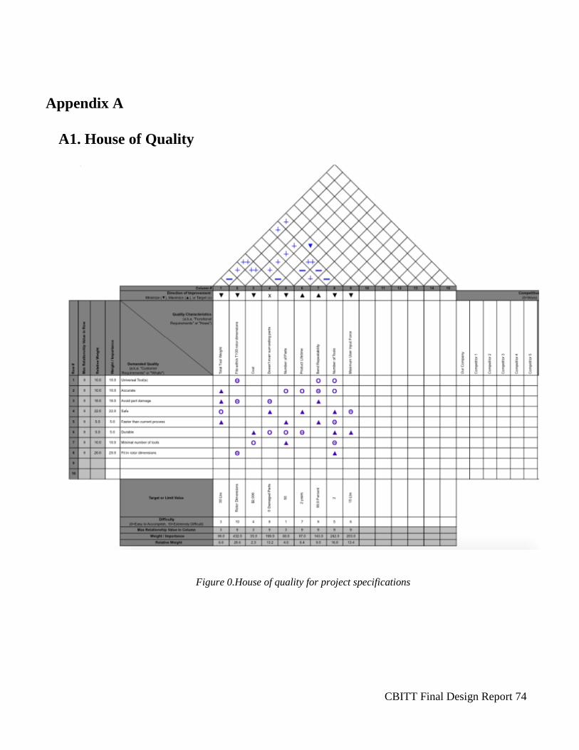
CBITT Final Design Report 74
Figure 0.House of quality for project specifications
Appendix A
A1. House of Quality

CBITT Final Design Report 75
A2. Morphological Matrix
Table 0.1 Morphological matrix for ideation
Power Hand Power Pneumatic Hydraulic Electric
Backer Release
Mechanism Vice-Grips
Quick
Release/Cam Pressure Release
Pen Clicking
Mechanism
Channel+Barrel
Rotation Unscrew
Bender Head Cam Profile Cam Profile
with Notch Wedge/Ramp
Switchable
Wedge Angles Curve
Rotating
Lever
Flexing
Lever
User Movement Ratchet Press Button Turn Squeeze Pump Push/Pull Hammer
Tool Movement Lever Screw Ratchet Linear Scissor Lift Car Jack None
Multi-Blade
Access
Jointed Belt
Around
Middle-Radius/
Contoured Plate
Multiple
Benders
Connected
None
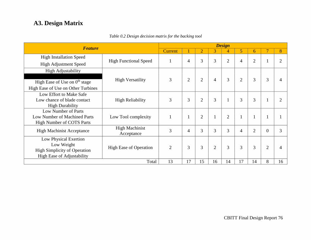
CBITT Final Design Report 76
A3. Design Matrix
Table 0.2 Design decision matrix for the backing tool
Feature Design
Current 1 2 3 4 5 6 7 8
High Installation Speed High Functional Speed 1 4 3 3 2 4 2 1 2
High Adjustment Speed
High Adjustability
High Versatility 3 2 2 4 3 2 3 3 4
High Ease of Use on 0th stage
High Ease of Use on Other Turbines
Low Effort to Make Safe
High Reliability 3 3 2 3 1 3 3 1 2 Low chance of blade contact
High Durability
Low Number of Parts
Low Tool complexity 1 1 2 1 2 1 1 1 1 Low Number of Machined Parts
High Number of COTS Parts
High Machinist Acceptance High Machinist
Acceptance 3 4 3 3 3 4 2 0 3
Low Physical Exertion
High Ease of Operation 2 3 3 2 3 3 3 2 4 Low Weight
High Simplicity of Operation
High Ease of Adjustability
Total 13 17 15 16 14 17 14 8 16
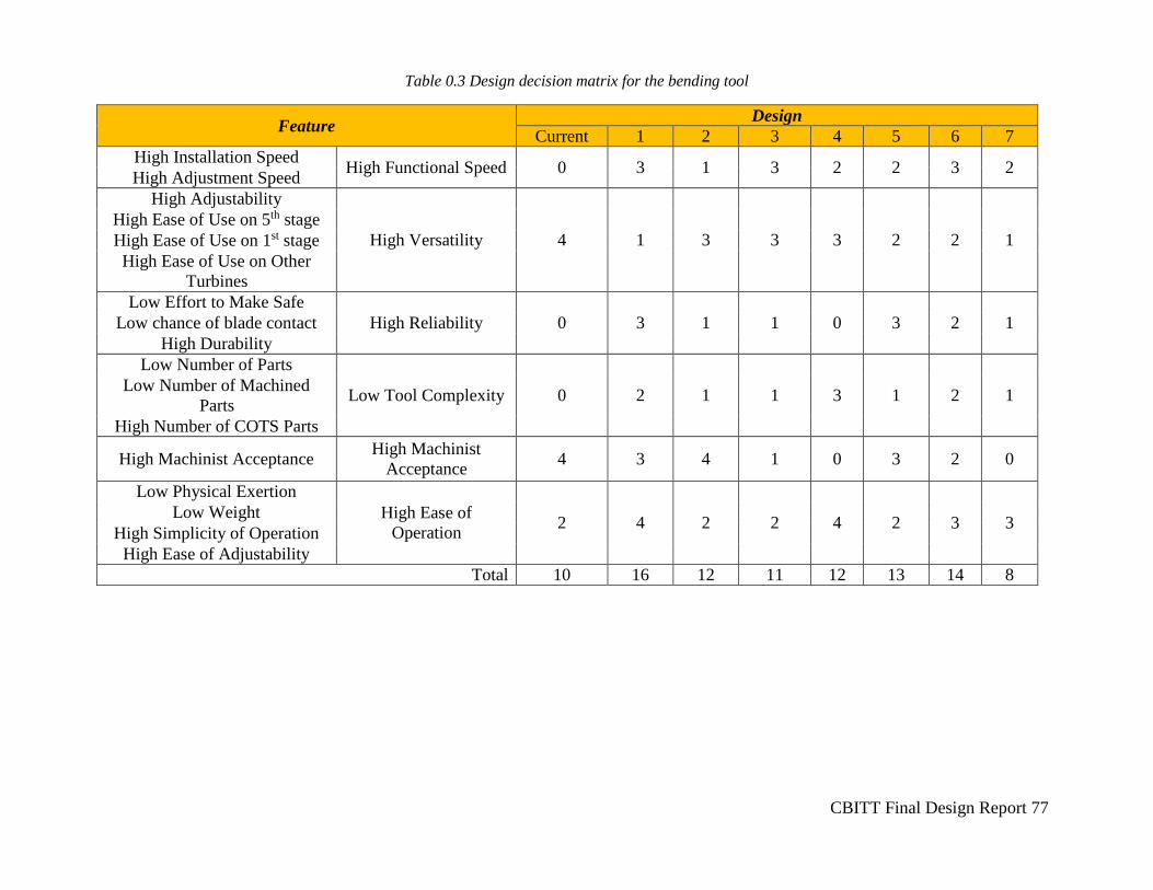
CBITT Final Design Report 77
Table 0.3 Design decision matrix for the bending tool
Feature Design
Current 1 2 3 4 5 6 7
High Installation Speed High Functional Speed 0 3 1 3 2 2 3 2
High Adjustment Speed
High Adjustability
High Versatility 4 1 3 3 3 2 2 1
High Ease of Use on 5th stage
High Ease of Use on 1st stage
High Ease of Use on Other
Turbines
Low Effort to Make Safe
High Reliability 0 3 1 1 0 3 2 1 Low chance of blade contact
High Durability
Low Number of Parts
Low Tool Complexity 0 2 1 1 3 1 2 1 Low Number of Machined
Parts
High Number of COTS Parts
High Machinist Acceptance High Machinist
Acceptance 4 3 4 1 0 3 2 0
Low Physical Exertion
High Ease of
Operation 2 4 2 2 4 2 3 3
Low Weight
High Simplicity of Operation
High Ease of Adjustability
Total 10 16 12 11 12 13 14 8
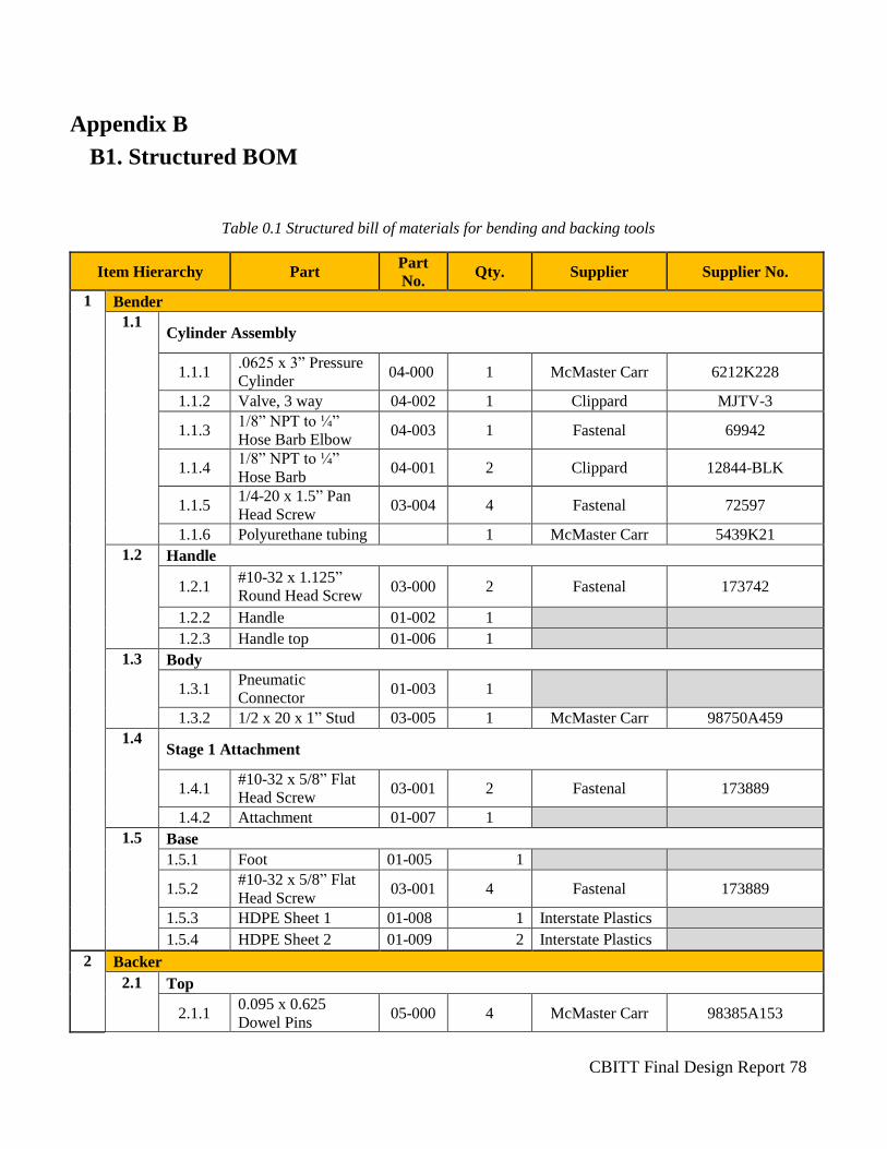
CBITT Final Design Report 78
Appendix B
B1. Structured BOM
Table 0.1 Structured bill of materials for bending and backing tools
Item Hierarchy Part Part
No. Qty. Supplier Supplier No.
1 Bender
1.1 Cylinder Assembly
1.1.1 .0625 x 3” Pressure
Cylinder 04-000 1 McMaster Carr 6212K228
1.1.2 Valve, 3 way 04-002 1 Clippard MJTV-3
1.1.3 1/8” NPT to ¼”
Hose Barb Elbow 04-003 1 Fastenal 69942
1.1.4 1/8” NPT to ¼”
Hose Barb 04-001 2 Clippard 12844-BLK
1.1.5 1/4-20 x 1.5” Pan
Head Screw 03-004 4 Fastenal 72597
1.1.6 Polyurethane tubing 1 McMaster Carr 5439K21
1.2 Handle
1.2.1 #10-32 x 1.125”
Round Head Screw 03-000 2 Fastenal 173742
1.2.2 Handle 01-002 1
1.2.3 Handle top 01-006 1
1.3 Body
1.3.1 Pneumatic
Connector 01-003 1
1.3.2 1/2 x 20 x 1” Stud 03-005 1 McMaster Carr 98750A459
1.4 Stage 1 Attachment
1.4.1 #10-32 x 5/8” Flat
Head Screw 03-001 2 Fastenal 173889
1.4.2 Attachment 01-007 1
1.5 Base
1.5.1 Foot 01-005 1
1.5.2 #10-32 x 5/8” Flat
Head Screw 03-001 4 Fastenal 173889
1.5.3 HDPE Sheet 1 01-008 1 Interstate Plastics
1.5.4 HDPE Sheet 2 01-009 2 Interstate Plastics
2 Backer
2.1 Top
2.1.1 0.095 x 0.625
Dowel Pins 05-000 4 McMaster Carr 98385A153
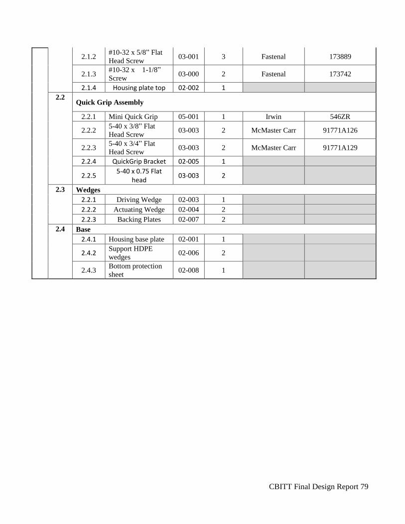
CBITT Final Design Report 79
2.1.2 #10-32 x 5/8” Flat
Head Screw 03-001 3 Fastenal 173889
2.1.3 #10-32 x 1-1/8”
Screw 03-000 2 Fastenal 173742
2.1.4 Housing plate top 02-002 1
2.2 Quick Grip Assembly
2.2.1 Mini Quick Grip 05-001 1 Irwin 546ZR
2.2.2 5-40 x 3/8” Flat
Head Screw 03-003 2 McMaster Carr 91771A126
2.2.3 5-40 x 3/4” Flat
Head Screw 03-003 2 McMaster Carr 91771A129
2.2.4 QuickGrip Bracket 02-005 1
2.2.5 5-40 x 0.75 Flat
head 03-003 2
2.3 Wedges
2.2.1 Driving Wedge 02-003 1
2.2.2 Actuating Wedge 02-004 2
2.2.3 Backing Plates 02-007 2
2.4 Base
2.4.1 Housing base plate 02-001 1
2.4.2 Support HDPE
wedges 02-006 2
2.4.3 Bottom protection
sheet 02-008 1

CBITT Final Design Report 80
B2. Part and Assembly Drawings
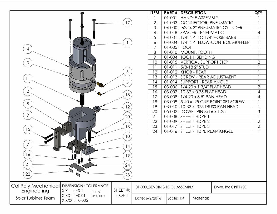
6
2
17
3
5
1
18
11
12
20
13
10
7 14
19
23
21 24
22
16
8
15
9
4
UNLESS
Date: 6/2/2016
Drwn. By: CBITT (SO)01-000_BENDING TOOL ASSEMBLY
Scale: 1:4 Solar Turbines Team SPECIFIEDEngineering
Material:
Cal Poly Mechanical
0.005
DIMENSION : TOLERANCEX.X : 0.1X.XX : 0.01X.XXX :
SHEET #:1 OF 1
ITEM PART # DESCRIPTION QTY.1 01-001 HANDLE ASSEMBLY 12 01-003 CONNECTOR, PNEUMATIC 13 04-000 .625 x 3" PNEUMATIC CYLINDER 14 01-018 SPACER - PNEUMATIC 45 04-001 1/4" NPT TO 1/4" HOSE BARB 16 04-004 1/4" NPT FLOW-CONTROL MUFFLER 17 01-005 FOOT 18 01-010 MOUNT, TOOTH 19 01-004 TOOTH, BENDING 1
10 01-015 VERTICAL SUPPORT STEP 211 01-011 5/8-18 2" STUD 112 01-012 KNOB - REAR 113 01-013 SCREW - REAR ADJUSTMENT 114 01-014 SUPPORT - REAR ANGLE 115 03-006 1/4-20 x 1 3/4" FLAT HEAD 216 03-007 10-32 x 0.75 FLAT HEAD 417 03-008 1/4-20 x 3.5" PAN HEAD 418 03-009 5-40 x .25 CUP POINT SET SCREW 119 03-010 10-32 x .375 TRUSS PAN HEAD 120 05-002 DOWEL PIN 3/16 x 1.25 321 01-008 SHEET - HDPE 1 122 01-009 SHEET - HDPE 2 223 01-017 SHEET - HDPE 3 224 01-016 SHEET - HDPE REAR ANGLE 1
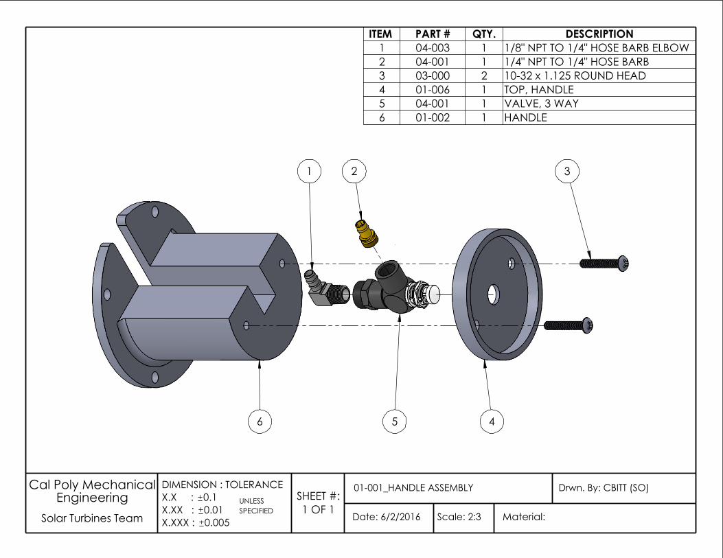
ITEM PART # QTY. DESCRIPTION1 04-003 1 1/8" NPT TO 1/4" HOSE BARB ELBOW2 04-001 1 1/4" NPT TO 1/4" HOSE BARB3 03-000 2 10-32 x 1.125 ROUND HEAD4 01-006 1 TOP, HANDLE5 04-001 1 VALVE, 3 WAY6 01-002 1 HANDLE
UNLESS
Date: 6/2/2016
Drwn. By: CBITT (SO)01-001_HANDLE ASSEMBLY
Scale: 2:3 Solar Turbines TeamSPECIFIED
EngineeringMaterial:
Cal Poly Mechanical
0.005
DIMENSION : TOLERANCEX.X : 0.1X.XX : 0.01X.XXX :
SHEET #:1 OF 1
5
1 2 3
46
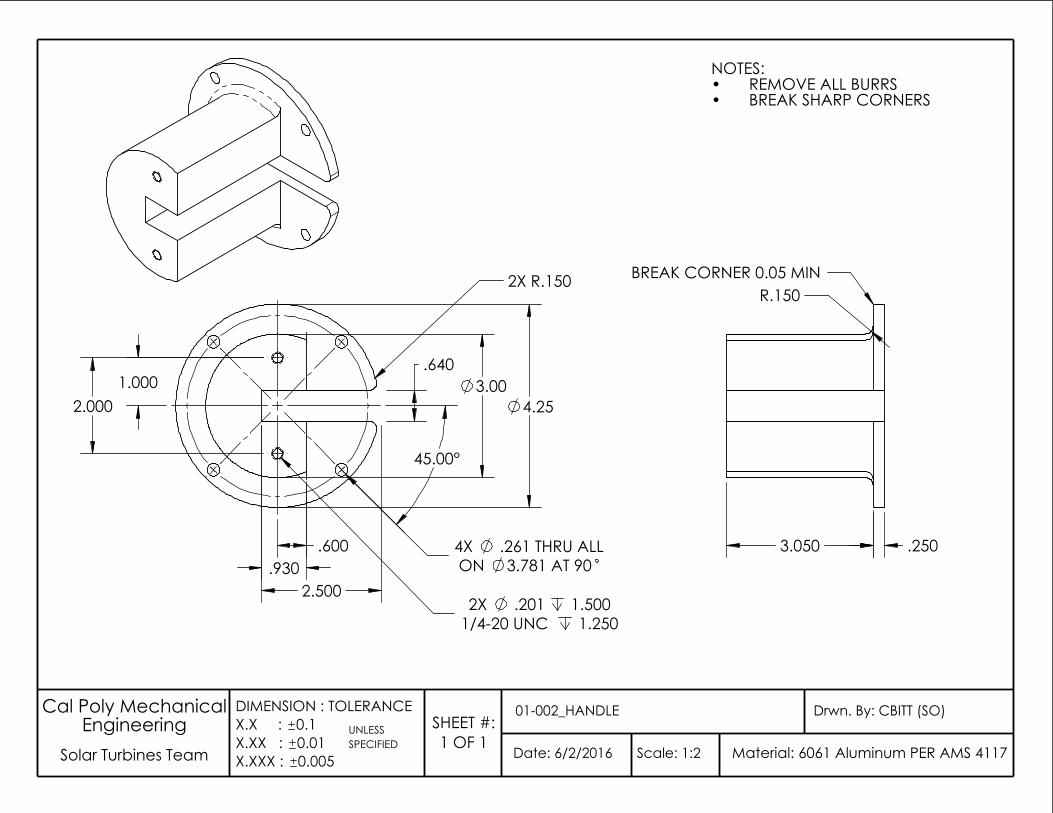
UNLESS
Date: 6/2/2016
Drwn. By: CBITT (SO)01-002_HANDLE
Scale: 1:2 Solar Turbines TeamSPECIFIED
EngineeringMaterial: 6061 Aluminum PER AMS 4117
Cal Poly Mechanical
0.005
DIMENSION : TOLERANCEX.X : 0.1X.XX : 0.01X.XXX :
SHEET #:1 OF 1
NOTES:REMOVE ALL BURRS•BREAK SHARP CORNERS•
BREAK CORNER 0.05 MIN
.250 3.050
R.150
4.25
3.781 AT 90
3.00
.930
45.00°
.600
2.500
.640
1/4-20 UNC 1.250
2.000
.201 1.5002X
4X .261 THRU ALLON
1.000
2X R.150
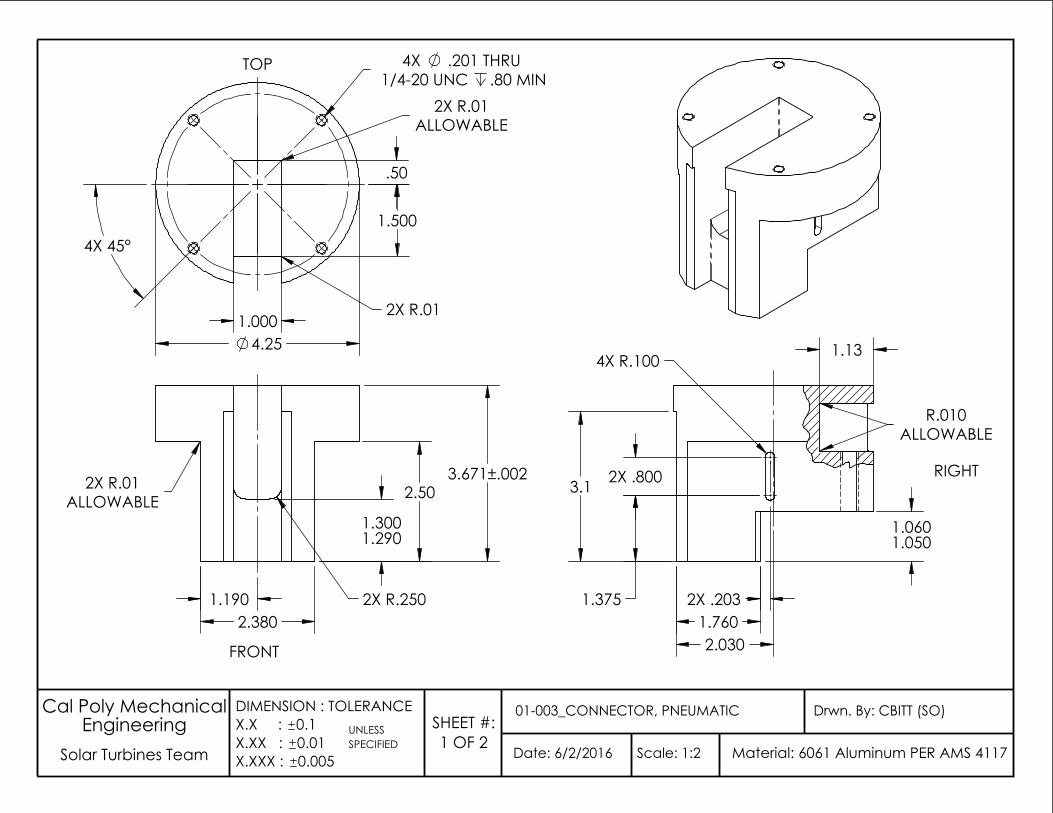
UNLESS
Date: 6/2/2016
Drwn. By: CBITT (SO)01-003_CONNECTOR, PNEUMATIC
Scale: 1:2 Solar Turbines TeamSPECIFIED
EngineeringMaterial: 6061 Aluminum PER AMS 4117
Cal Poly Mechanical
0.005
DIMENSION : TOLERANCEX.X : 0.1X.XX : 0.01X.XXX :
SHEET #:1 OF 2
FRONT
2.380
2.50
2X R.250
3.671±.002
1.3001.290
1.190
2X R.01ALLOWABLE
TOP
1.500
4.25 1.000
.50
1/4-20 UNC
ALLOWABLE
.80 MIN2X R.01
2X R.01
4X .201 THRU
4X 45°
RIGHT
1.760
1.050
1.13
2.030
ALLOWABLE
3.1
R.010
2X .800
4X R.100
2X .203
1.060
1.375
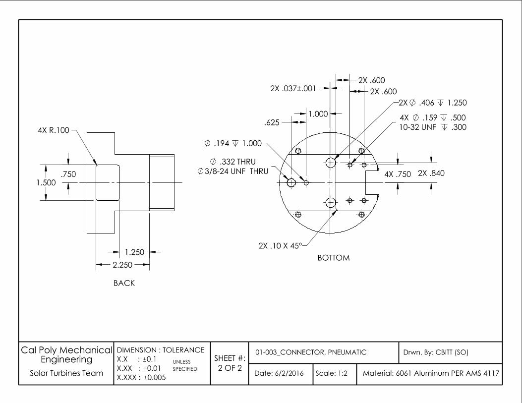
Date: 6/2/2016
Drwn. By: CBITT (SO)01-003_CONNECTOR, PNEUMATIC
Scale: 1:2 Solar Turbines Team
Cal Poly Mechanical Engineering
Material: 6061 Aluminum PER AMS 4117
DIMENSION : TOLERANCEX.X : 0.1X.XX : 0.01X.XXX : 0.005
UNLESS SPECIFIED
SHEET #:2 OF 2
BOTTOM
4X .159 .50010-32 UNF .300
2X .600 2X .600
2X .406 1.250
.332 THRU3/8-24 UNF THRU
.194 1.000
.625
2X .10 X 45°
4X .750 2X .840
2X .037±.001
1.000
BACK
1.500
2.250
4X R.100
.750
1.250
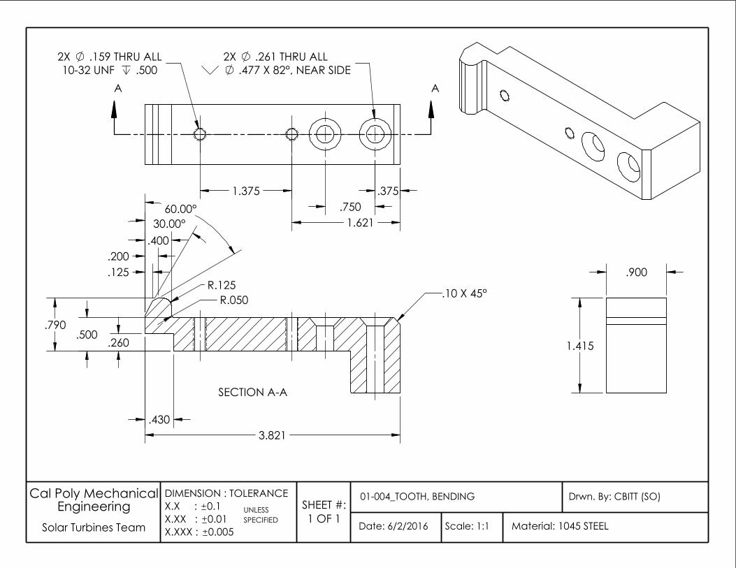
UNLESS
Date: 6/2/2016
Drwn. By: CBITT (SO)01-004_TOOTH, BENDING
Scale: 1:1 Solar Turbines TeamSPECIFIED
EngineeringMaterial: 1045 STEEL
Cal Poly Mechanical
0.005
DIMENSION : TOLERANCEX.X : 0.1X.XX : 0.01X.XXX :
SHEET #:1 OF 1
.477 X 82°, NEAR SIDE
1.375
10-32 UNF .500
.375
.159 THRU ALL2X
1.621
2X .261 THRU ALL
.750
AA
SECTION A-A
.430
R.050
.400
60.00°
.260
R.125 .125
30.00°
.500
.200
.790
3.821
.10 X 45°
.900
1.415
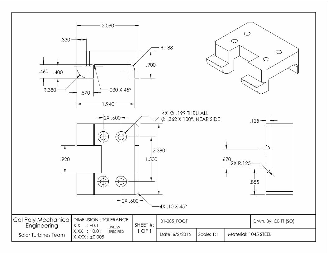
UNLESS
Date: 6/2/2016
Drwn. By: CBITT (SO)01-005_FOOT
Scale: 1:1 Solar Turbines TeamSPECIFIED
EngineeringMaterial: 1045 STEEL
Cal Poly Mechanical
0.005
DIMENSION : TOLERANCEX.X : 0.1X.XX : 0.01X.XXX :
SHEET #:1 OF 1
2X .600
2.380
.920
2X .600 .362 X 100°, NEAR SIDE4X .199 THRU ALL
1.500
4X .10 X 45°
.670 2X R.125
.125
.855
.460
.330
R.380 .570
2.090
.400
1.940
.030 X 45°
.900
R.188
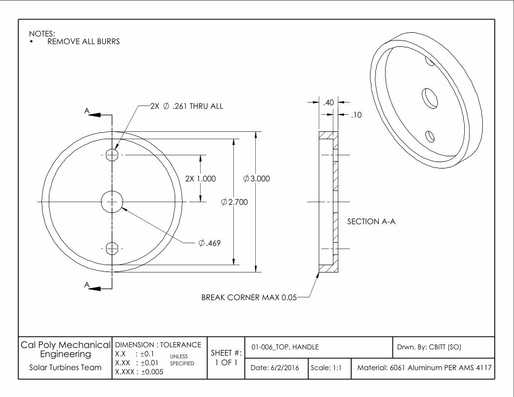
UNLESS
Date: 6/2/2016
Drwn. By: CBITT (SO)01-006_TOP, HANDLE
Scale: 1:1 Solar Turbines Team SPECIFIEDEngineering
Material: 6061 Aluminum PER AMS 4117
Cal Poly Mechanical
0.005
DIMENSION : TOLERANCEX.X : 0.1X.XX : 0.01X.XXX :
SHEET #:1 OF 1
NOTES:REMOVE ALL BURRS•
2X .261 THRU ALL
3.000
2.700
.469
2X 1.000
A
ABREAK CORNER MAX 0.05
SECTION A-A
.10 .40
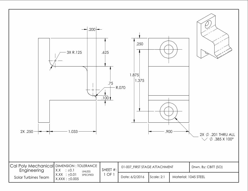
.75
.100
1.033 2X .250
3X R.125
.200
.625
R.070
1.875
.900
.385 X 100°
.250
2X .201 THRU ALL
1.375
UNLESS
Date: 6/2/2016
Drwn. By: CBITT (SO)01-007_FIRST STAGE ATTACHMENT
Scale: 2:1 Solar Turbines TeamSPECIFIED
EngineeringMaterial: 1045 STEEL
Cal Poly Mechanical
0.005
DIMENSION : TOLERANCEX.X : 0.1X.XX : 0.01X.XXX :
SHEET #:1 OF 1
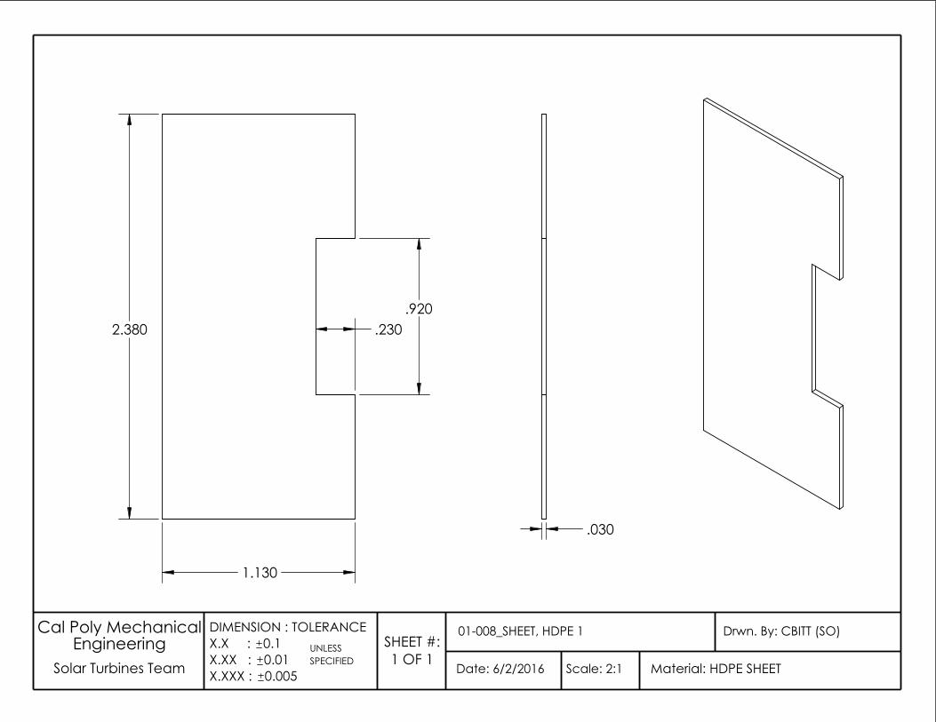
UNLESS
Date: 6/2/2016
Drwn. By: CBITT (SO)01-008_SHEET, HDPE 1
Scale: 2:1 Solar Turbines Team SPECIFIEDEngineering
Material: HDPE SHEET
Cal Poly Mechanical
0.005
DIMENSION : TOLERANCEX.X : 0.1X.XX : 0.01X.XXX :
SHEET #:1 OF 1
2.380
1.130
.920 .230
.030
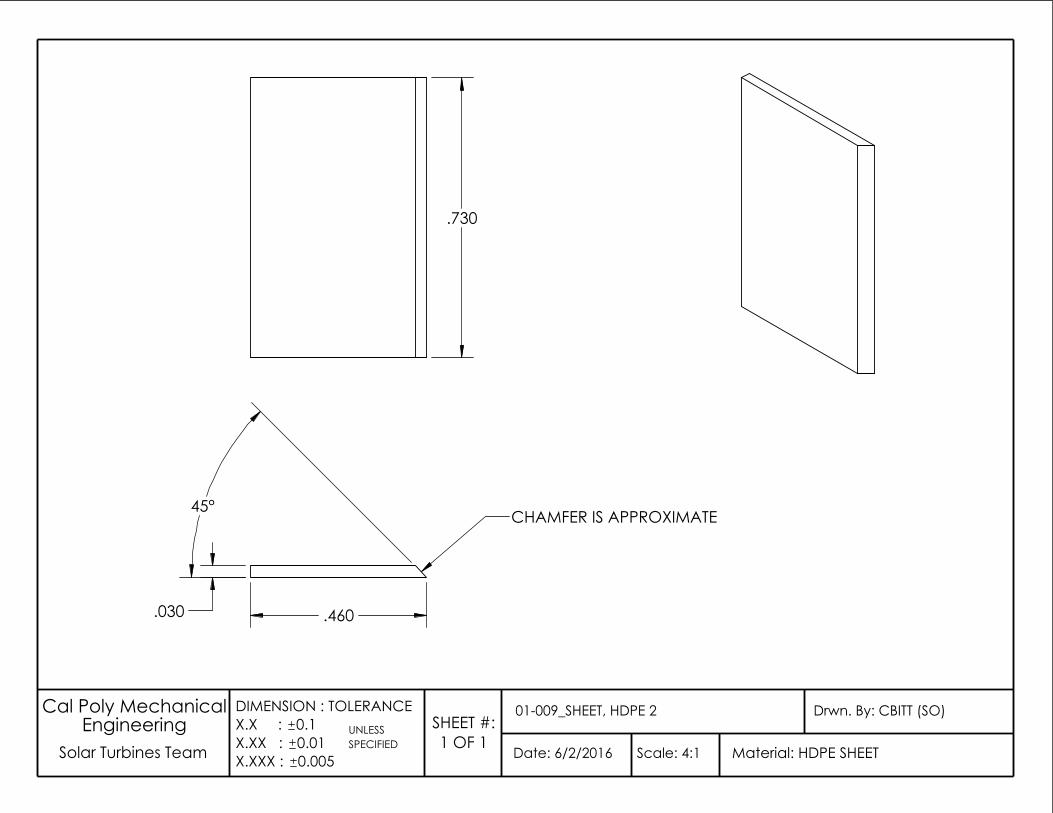
UNLESS
Date: 6/2/2016
Drwn. By: CBITT (SO)01-009_SHEET, HDPE 2
Scale: 4:1 Solar Turbines Team SPECIFIEDEngineering
Material: HDPE SHEET
Cal Poly Mechanical
0.005
DIMENSION : TOLERANCEX.X : 0.1X.XX : 0.01X.XXX :
SHEET #:1 OF 1
.730
CHAMFER IS APPROXIMATE
.460 .030
45°
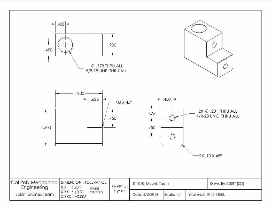
UNLESS
Date: 6/2/2016
Drwn. By: CBITT (SO)01-010_Mount, Tooth
Scale: 1:1 Solar Turbines Team SPECIFIEDEngineering
Material: 1045 STEEL
Cal Poly Mechanical
0.005
DIMENSION : TOLERANCEX.X : 0.1X.XX : 0.01X.XXX :
SHEET #:1 OF 1
1.500
1.900 .625
.750
.02 X 45° .450
2X .10 X 45°
1/4-20 UNC THRU ALL .201 THRU ALL .375 2X
.750
.400
.900
5/8-18 UNF THRU ALL .578 THRU ALL
.450
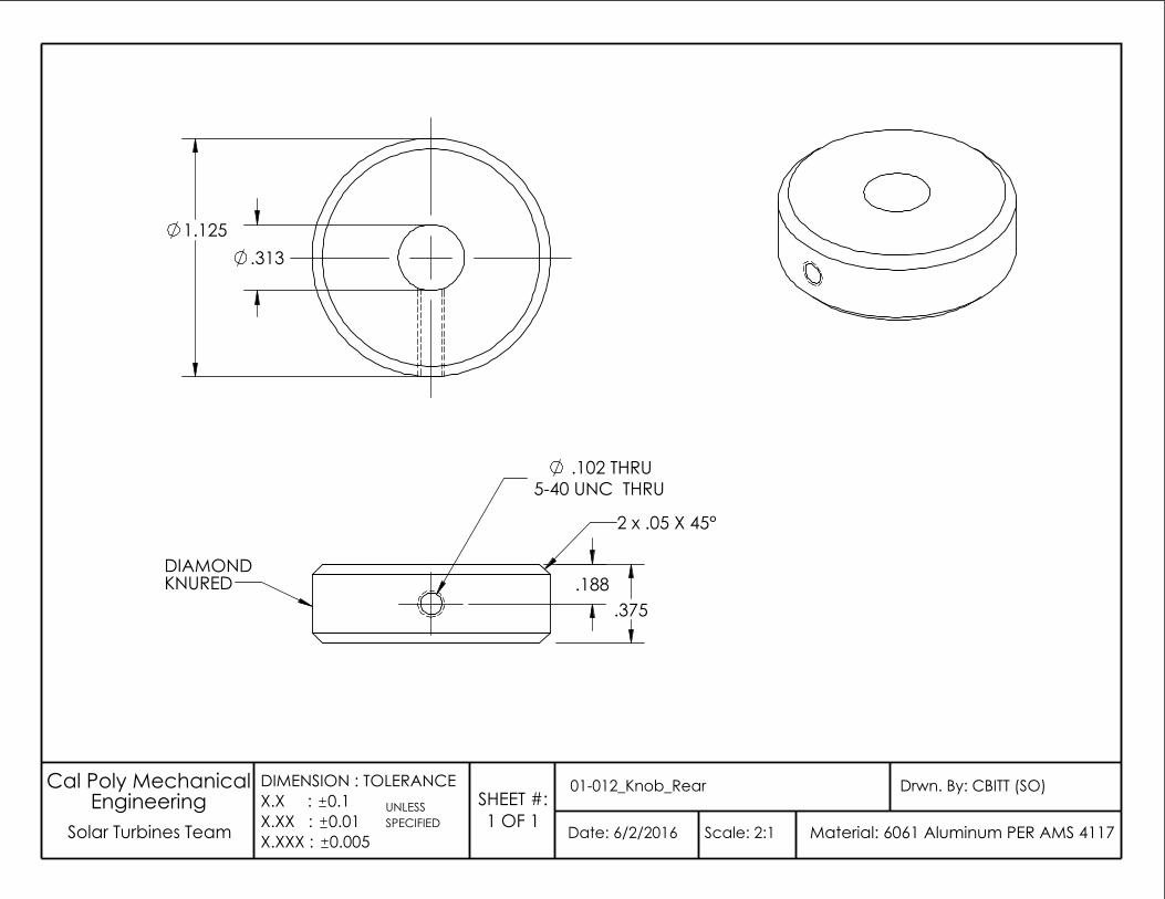
UNLESS
Date: 6/2/2016
Drwn. By: CBITT (SO)01-012_Knob_Rear
Scale: 2:1 Solar Turbines Team SPECIFIEDEngineering
Material: 6061 Aluminum PER AMS 4117
Cal Poly Mechanical
0.005
DIMENSION : TOLERANCEX.X : 0.1X.XX : 0.01X.XXX :
SHEET #:1 OF 1
DIAMONDKNURED
.102 THRU5-40 UNC THRU
.375
2 x .05 X 45°
.188
.313 1.125
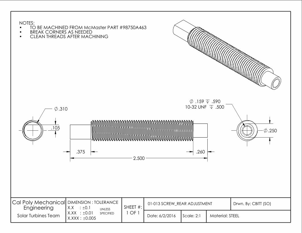
.250
.159 .59010-32 UNF .500.310
.105
NOTES:TO BE MACHINED FROM McMaster PART #98750A463•BREAK CORNERS AS NEEDED•CLEAN THREADS AFTER MACHINING•
UNLESS
Date: 6/2/2016
Drwn. By: CBITT (SO)01-013 SCREW_REAR ADJUSTMENT
Scale: 2:1 Solar Turbines Team SPECIFIEDEngineering
Material: STEEL
Cal Poly Mechanical
0.005
DIMENSION : TOLERANCEX.X : 0.1X.XX : 0.01X.XXX :
SHEET #:1 OF 1
.375 .260 2.500
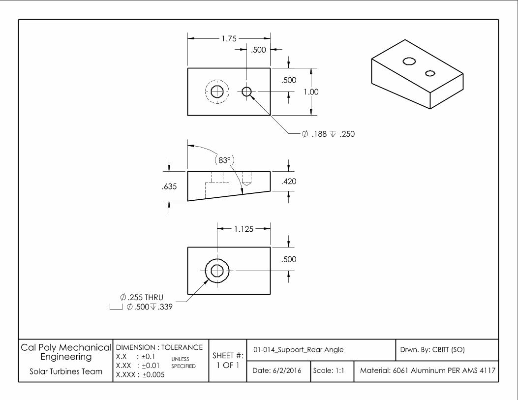
.635 .420
83°
.188 .250
1.75
1.00
.500
.500
.339
.500
.500.255 THRU
1.125
UNLESS
Date: 6/2/2016
Drwn. By: CBITT (SO)01-014_Support_Rear Angle
Scale: 1:1 Solar Turbines TeamSPECIFIED
EngineeringMaterial: 6061 Aluminum PER AMS 4117
Cal Poly Mechanical
0.005
DIMENSION : TOLERANCEX.X : 0.1X.XX : 0.01X.XXX :
SHEET #:1 OF 1
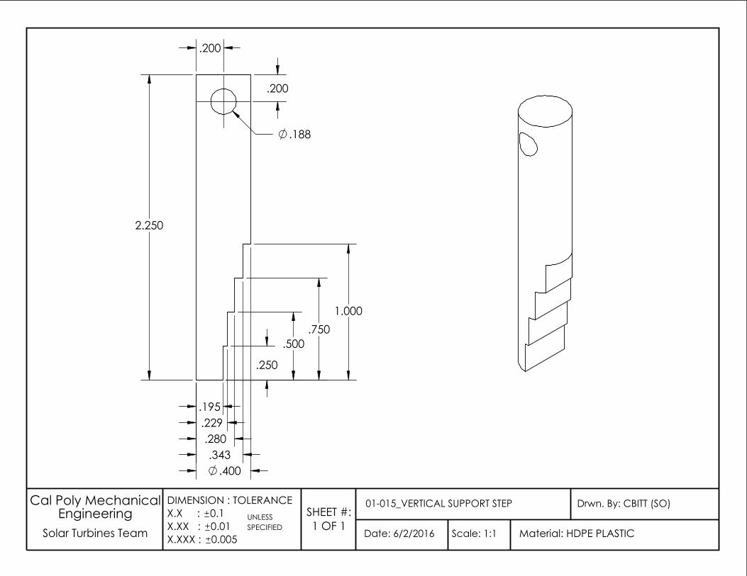
0.005
UNLESS
Date: 6/2/2016
Drwn. By: CBITT (SO)01-015_VERTICAL SUPPORT STEP
Scale: 1:1 SPECIFIED
EngineeringSolar Turbines Team
Cal Poly Mechanical
Material: HDPE PLASTIC
DIMENSION : TOLERANCEX.X : 0.1X.XX : 0.01X.XXX :
SHEET #:1 OF 1
1.000
.200
.400 .343
.280 .229 .195
.188
2.250
.250
.500 .750
.200
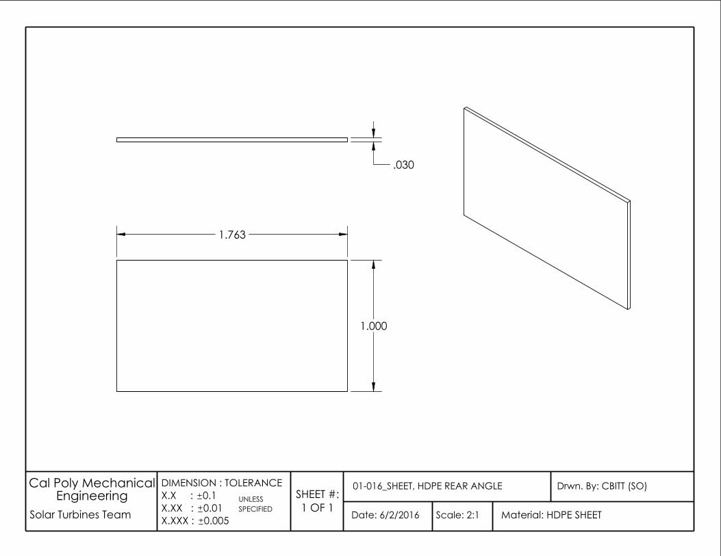
0.005
UNLESS
Date: 6/2/2016
Drwn. By: CBITT (SO)01-016_SHEET, HDPE REAR ANGLE
Scale: 2:1 SPECIFIED
EngineeringSolar Turbines Team
Cal Poly Mechanical
Material: HDPE SHEET
DIMENSION : TOLERANCEX.X : 0.1X.XX : 0.01X.XXX :
SHEET #:1 OF 1
1.763
1.000
.030
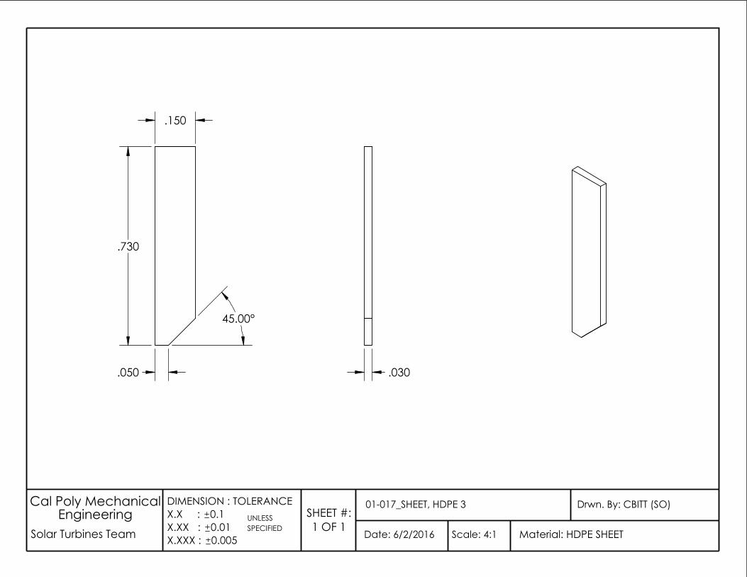
.030
.730
45.00°
.150
.050
0.005
UNLESS
Date: 6/2/2016
Drwn. By: CBITT (SO)01-017_SHEET, HDPE 3
Scale: 4:1 SPECIFIED
EngineeringSolar Turbines Team
Cal Poly Mechanical
Material: HDPE SHEET
DIMENSION : TOLERANCEX.X : 0.1X.XX : 0.01X.XXX :
SHEET #:1 OF 1
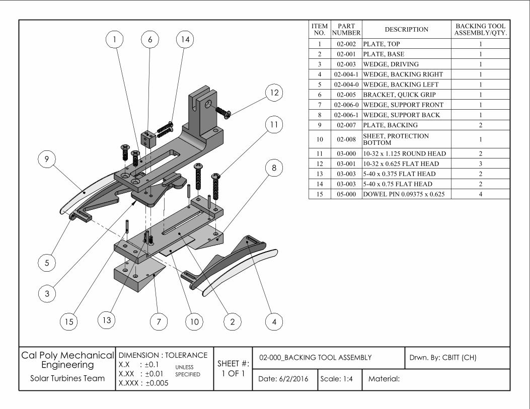
ITEM NO.
PART NUMBER DESCRIPTION BACKING TOOL
ASSEMBLY/QTY.
1 02-002 PLATE, TOP 12 02-001 PLATE, BASE 13 02-003 WEDGE, DRIVING 14 02-004-1 WEDGE, BACKING RIGHT 15 02-004-0 WEDGE, BACKING LEFT 16 02-005 BRACKET, QUICK GRIP 17 02-006-0 WEDGE, SUPPORT FRONT 18 02-006-1 WEDGE, SUPPORT BACK 19 02-007 PLATE, BACKING 2
10 02-008 SHEET, PROTECTION BOTTOM 1
11 03-000 10-32 x 1.125 ROUND HEAD 212 03-001 10-32 x 0.625 FLAT HEAD 313 03-003 5-40 x 0.375 FLAT HEAD 214 03-003 5-40 x 0.75 FLAT HEAD 215 05-000 DOWEL PIN 0.09375 x 0.625 4
0.005
UNLESS
Date: 6/2/2016
Drwn. By: CBITT (CH)02-000_BACKING TOOL ASSEMBLY
Scale: 1:4 SPECIFIED
EngineeringSolar Turbines Team
Cal Poly Mechanical
Material:
DIMENSION : TOLERANCEX.X : 0.1X.XX : 0.01X.XXX :
SHEET #:1 OF 1
5
3
9
6 14
12
11
4
8
21071315
1
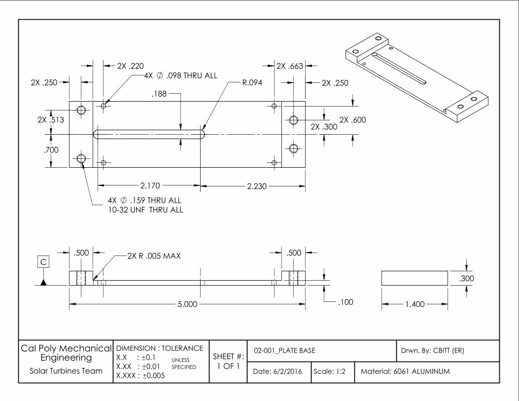
2X .250 R.094 .188
2X .600
2.170 2.230
.700
2X .250
2X .220 2X .663
10-32 UNF THRU ALL .159 THRU ALL
4X .098 THRU ALL
2X .300
4X
2X .513
1.400
.300
UNLESS
Date: 6/2/2016
Drwn. By: CBITT (ER)02-001_PLATE BASE
Scale: 1:2 Solar Turbines Team SPECIFIEDEngineering
Material: 6061 ALUMINUM
Cal Poly Mechanical
0.005
DIMENSION : TOLERANCEX.X : 0.1X.XX : 0.01X.XXX :
SHEET #:1 OF 1
2X R .005 MAXC
.500
5.000
.500
.100
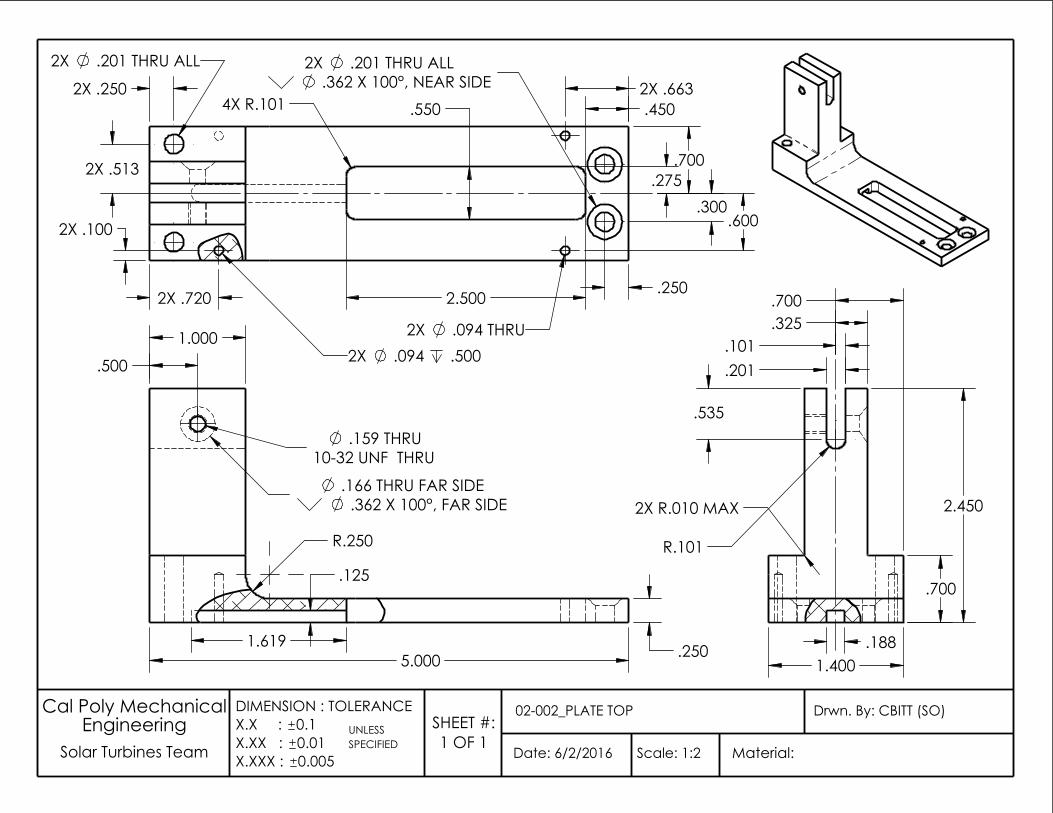
2X .201 THRU ALL
.550
.250
4X R.101 2X .663 .450
2X .720
2X .513
.362 X 100°, NEAR SIDE
.275 .300
.700
.600
.094 .500
2.500
.201 THRU ALL 2X .250
2X .100
2X
2X 2X .094 THRU
.700
.535
R.101
1.400
.201 .101
.325 .700
2.450
.188
2X R.010 MAX
.250 5.000
1.000
R.250
.500
1.619
.125
.362 X 100°, FAR SIDE .166 THRU FAR SIDE
.159 THRU10-32 UNF THRU
UNLESS
Date: 6/2/2016
Drwn. By: CBITT (SO)02-002_PLATE TOP
Scale: 1:2 Solar Turbines Team SPECIFIEDEngineering
Material:
Cal Poly Mechanical
0.005
DIMENSION : TOLERANCEX.X : 0.1X.XX : 0.01X.XXX :
SHEET #:1 OF 1
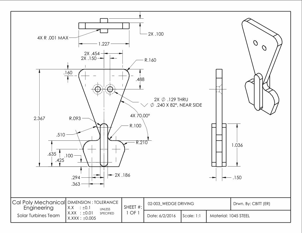
.240 X 82°, NEAR SIDE
R.093
.100
R.100
2X .150
.363
2X .186
.488 .160
2X .454
2.367
.425 .635
.510 R.210
2X .129 THRU
.294
4X 70.00°
R.160
UNLESS
Date: 6/2/2016
Drwn. By: CBITT (ER)02-003_WEDGE DRIVING
Scale: 1:1 Solar Turbines Team SPECIFIEDEngineering
Material: 1045 STEEL
Cal Poly Mechanical
0.005
DIMENSION : TOLERANCEX.X : 0.1X.XX : 0.01X.XXX :
SHEET #:1 OF 1
4X R .001 MAX 2X .100
1.227
1.036
.150
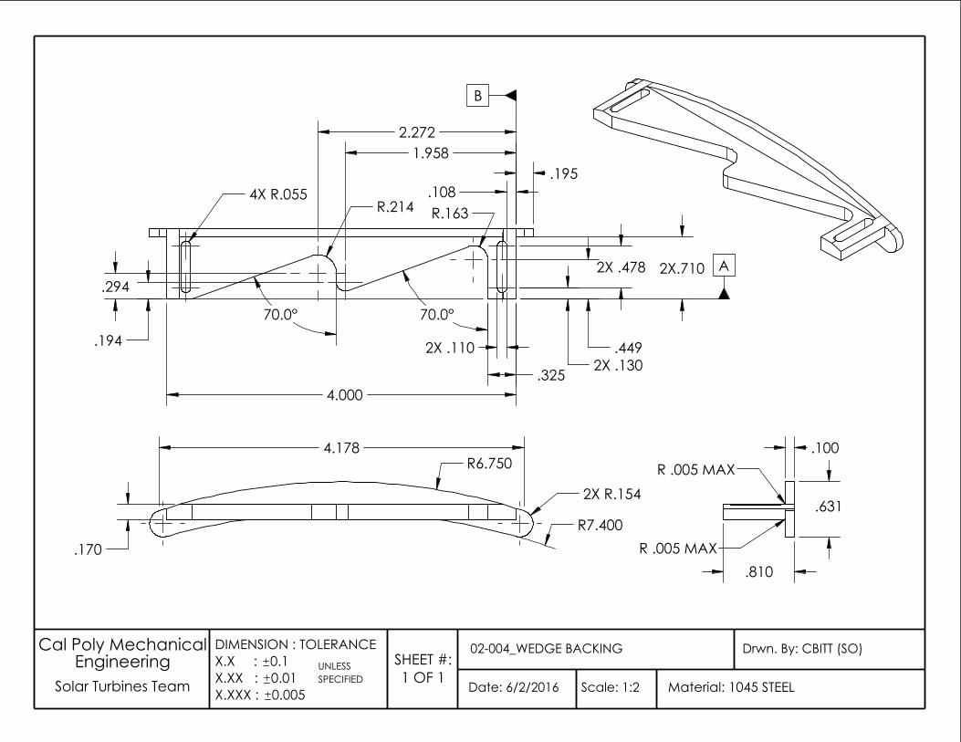
Solar Turbines Team
Cal Poly Mechanical
0.005
UNLESS
Date: 6/2/2016
Drwn. By: CBITT (SO)Engineering
Material: 1045 STEEL
02-004_WEDGE BACKING
Scale: 1:2 SPECIFIED
DIMENSION : TOLERANCEX.X : 0.1X.XX : 0.01X.XXX :
SHEET #:1 OF 1
4.178 R6.750
.170 R7.400
2X R.154
A
B
2X .130
70.0°
2X.710
R.163
.449
4.000
2X .478
4X R.055 .108
.194
.195
2X .110
R.214
70.0°
1.958
.325
2.272
.294
R .005 MAX
R .005 MAX
.631
.100
.810
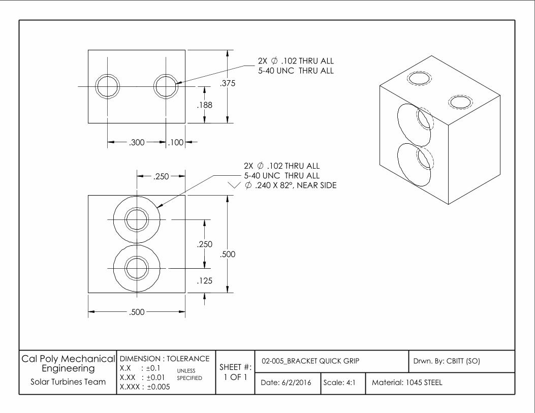
UNLESS
Date: 6/2/2016
Drwn. By: CBITT (SO)02-005_BRACKET QUICK GRIP
Scale: 4:1 Solar Turbines Team SPECIFIEDEngineering
Material: 1045 STEEL
Cal Poly Mechanical
0.005
DIMENSION : TOLERANCEX.X : 0.1X.XX : 0.01X.XXX :
SHEET #:1 OF 1
.240 X 82°, NEAR SIDE
.500
.125
.250
.250 2X .102 THRU ALL5-40 UNC THRU ALL
.500
.102 THRU ALL5-40 UNC THRU ALL
.100 .300
.188
2X
.375
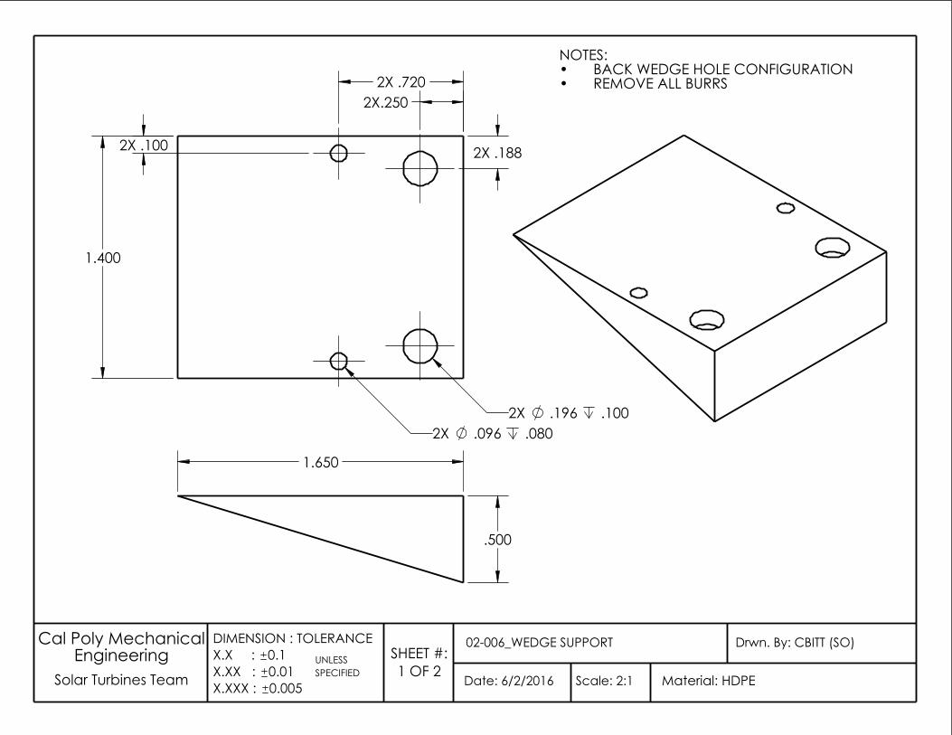
2X.250
1.400
2X .188 2X .100
2X .720
.196 2X .1002X .096 .080
.500
1.650
NOTES:BACK WEDGE HOLE CONFIGURATION•REMOVE ALL BURRS•
UNLESS
Date: 6/2/2016
Drwn. By: CBITT (SO)02-006_WEDGE SUPPORT
Scale: 2:1 Solar Turbines Team SPECIFIEDEngineering
Material: HDPE
Cal Poly Mechanical
0.005
DIMENSION : TOLERANCEX.X : 0.1X.XX : 0.01X.XXX :
SHEET #:1 OF 2
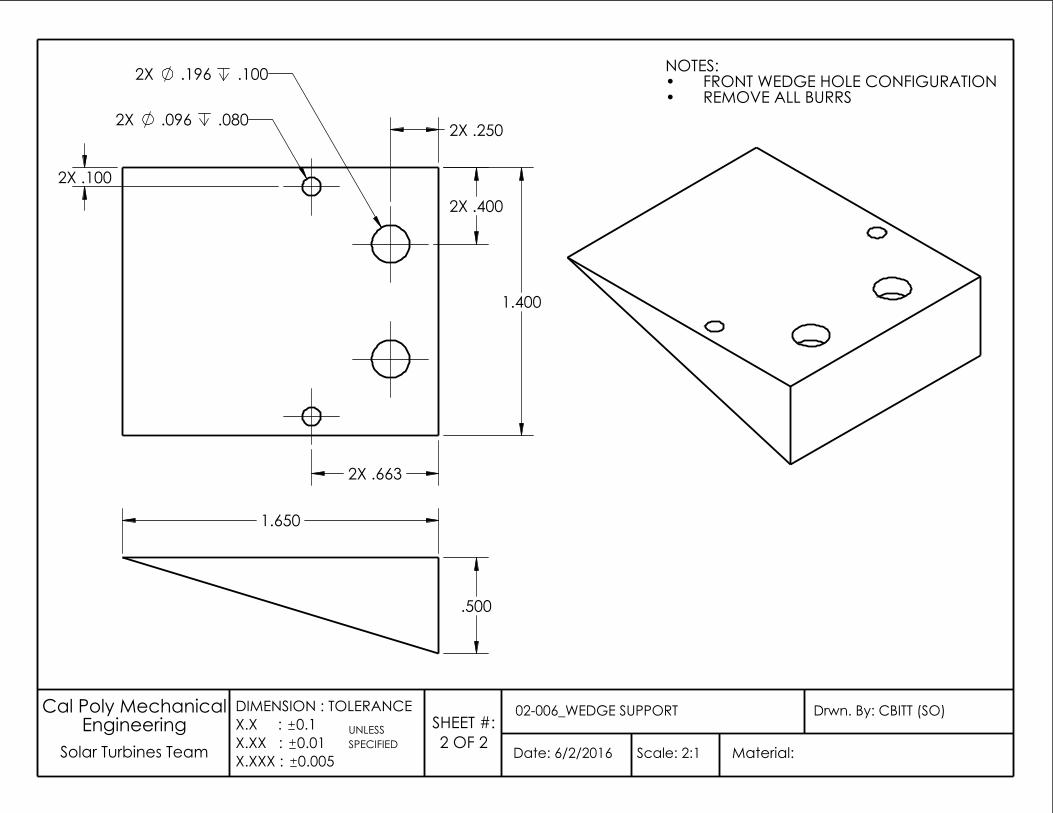
1.400
2X .196 .100
2X .400
2X .250 2X .096 .080
2X .100
2X .663
Date: 6/2/2016
Drwn. By: CBITT (SO)02-006_WEDGE SUPPORT
Scale: 2:1 Solar Turbines Team
Cal Poly Mechanical Engineering
Material:
DIMENSION : TOLERANCEX.X : 0.1X.XX : 0.01X.XXX : 0.005
UNLESS SPECIFIED
SHEET #:2 OF 2
NOTES:FRONT WEDGE HOLE CONFIGURATION•REMOVE ALL BURRS•
1.650
.500
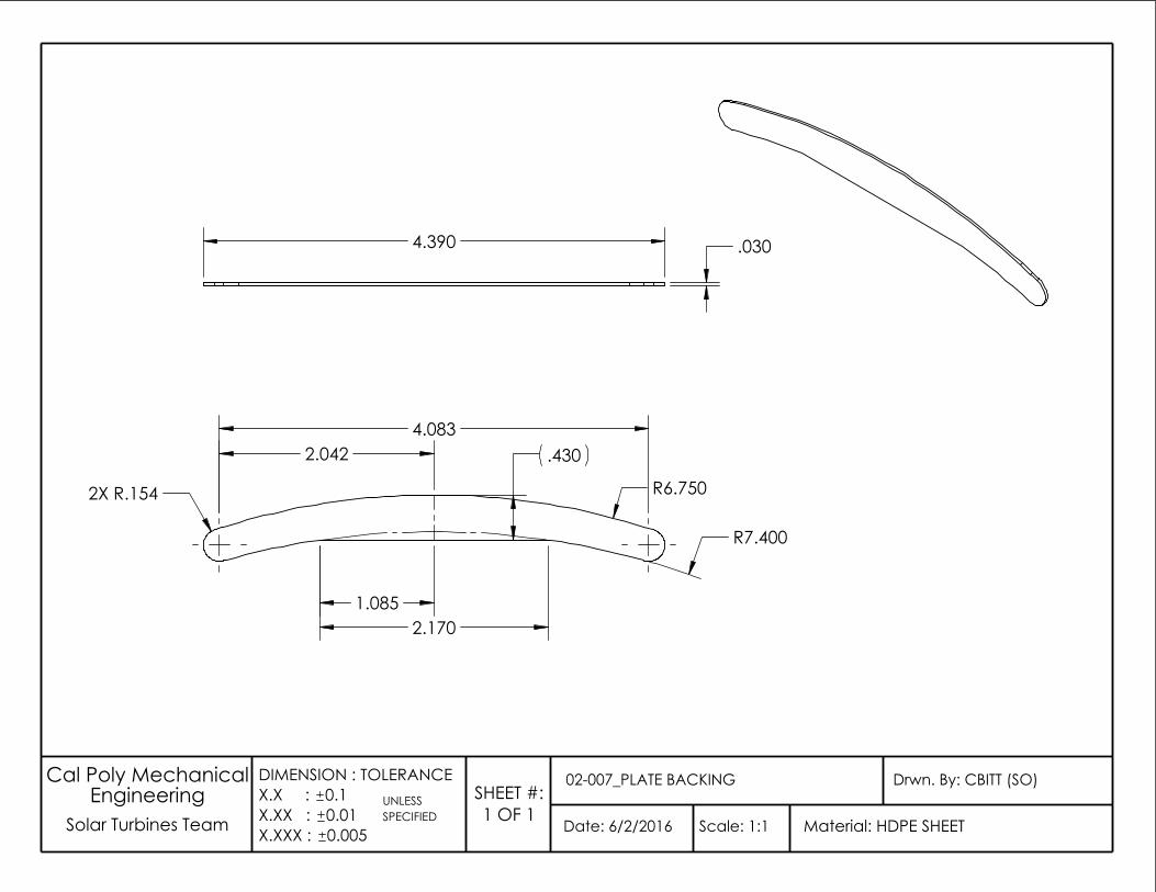
2.042
1.085
.430
R6.750
2.170
2X R.154
4.083
R7.400
4.390 .030
UNLESS
Date: 6/2/2016
Drwn. By: CBITT (SO)02-007_PLATE BACKING
Scale: 1:1 Solar Turbines Team SPECIFIEDEngineering
Material: HDPE SHEET
Cal Poly Mechanical
0.005
DIMENSION : TOLERANCEX.X : 0.1X.XX : 0.01X.XXX :
SHEET #:1 OF 1
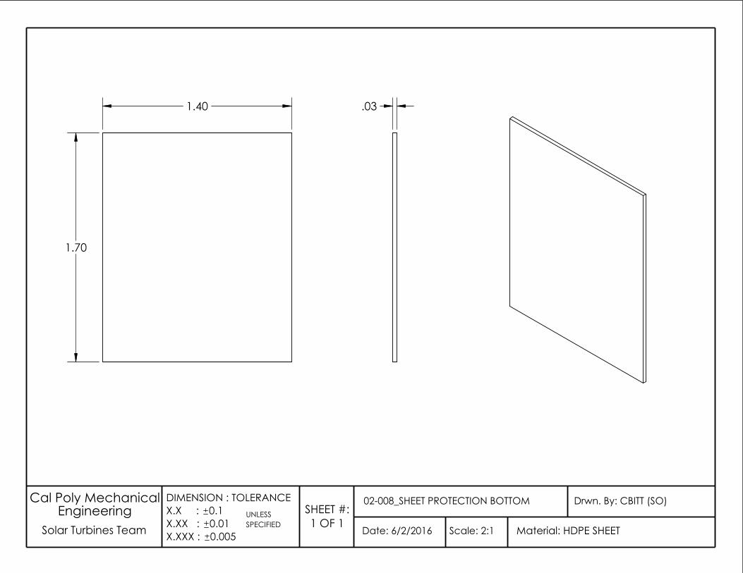
.03
UNLESS
Date: 6/2/2016
Drwn. By: CBITT (SO)02-008_SHEET PROTECTION BOTTOM
Scale: 2:1 Solar Turbines Team SPECIFIEDEngineering
Material: HDPE SHEET
Cal Poly Mechanical
0.005
DIMENSION : TOLERANCEX.X : 0.1X.XX : 0.01X.XXX :
SHEET #:1 OF 1
1.40
1.70
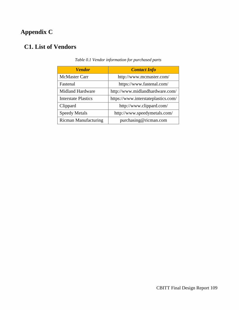
CBITT Final Design Report 109
Appendix C
C1. List of Vendors
Table 0.1 Vendor information for purchased parts
Vendor Contact Info
McMaster Carr http://www.mcmaster.com/
Fastenal https://www.fastenal.com/
Midland Hardware http://www.midlandhardware.com/
Interstate Plastics https://www.interstateplastics.com/
Clippard http://www.clippard.com/
Speedy Metals http://www.speedymetals.com/
Ricman Manufacturing [email protected]

CBITT Final Design Report 110
Appendix D
D1. Vendor Data Sheets
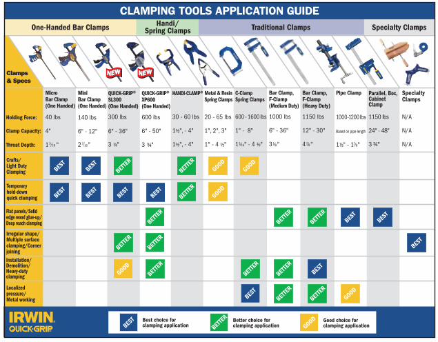
800.866.5740800.866.5740 www.irwin.com/quick-grip
Clamping Tools
CTP-080585
2008
8935 NorthPointe Executive Dr.Huntersville, NC 28078 - U.S.A.
Dealer:
File Name: CTP_080585_QuickGrp_Brochure_Out_r0.ai
Vendor: webbmas
Die Color (FPO) Die # Prints: 2 Sided
Date: 7/23/08 Artist: DB
IRWIN YELLOW IRWIN BLUE Process
PMS PMS PMS
Trim Size: 24.5 in. W x 11 in. H
The Complete Solution for Clamping
IRWIN® QUICK-GRIP® can deliver the right fit, features and pressure for any clamping job – from the smallest craft project to large scale cabinetry. So whether you need the one-handed power of the new QUICK-GRIP XP600 or the versatility of the new SL300 clamp, you can be sure you will get the clamping performance you need when you reach for the one with the QUICK-GRIP brand.
Holding Force:
Clamp Capacity:
Throat Depth:
Crafts/Light DutyClamping
Temporary hold-downquick clamping
Flat panels/Solidedge wood glue-up/Deep reach clamping
Irregular shape/Multiple surfaceclamping/CornerjoiningInstallation/Demolition/Heavy-dutyclamping
Localizedpressure/Metal working
BEST
Clamps& Specs
BETTE
R
BETTE
R
GOOD
GOODGOOD
BETTE
R
BETTE
R
BETTE
R
BETTE
R
BETTE
R
BEST
BEST
BEST
BEST
GOOD
BETTE
R
BEST
BETTE
R
BETTE
R
BETTE
R
BETTE
R
BEST
BEST
BEST
BEST
BEST
BETTE
R
GOOD
Best choice forclamping applicationBES
T Better choice forclamping applicationBET
TER Good choice for
clamping applicationGOOD
One-Handed Bar Clamps Traditional Clamps Specialty ClampsHandi/Spring Clamps
MicroBar Clamp(One Handed)
40 lbs
4"
1 " /3 16
MiniBar Clamp(One Handed)
140 lbs
6" - 12"
2 " /7 16
QUICK-GRIP®SL300(One Handed)
300 lbs
6" - 36"
3 ¼"
QUICK-GRIP® XP600(One Handed)
600 lbs
6" - 50"
3 ¾"
HANDI-CLAMP®
30 - 60 lbs
1½", - 4"
1½", - 4"
Metal & ResinSpring Clamps
20 - 65 lbs
1", 2", 3"
1 " - 4 ½"
C-ClampSpring Clamps
600 - 1600 lbs
1" - 8"
1 " - 4 ½"
Bar Clamp,F-Clamp(Medium Duty)
1000 lbs
6" - 36"
3 "
CLAMPING TOOLS APPLICATION GUIDE
3 16 1 8
Bar Clamp,F-Clamp(Heavy Duty)
1150 lbs
12" - 30"
4 " 7 8
Pipe Clamp
1000-1200 lbs
Based on pipe length
1½" - 1 " 7 8
Parallel, Box, CabinetClamp
1150 lbs
24" - 48"
3 ¾"
SpecialtyClamps
N/A
N/A
N/A
Bar Clamps
Specialty Clamps/Vises
226100 1" x 15' Band Clamp 0 38548 01490 6 1226200 3" Corner Clamp 0 38548 01491 3 1226410 90° Angle Clamp 0 38548 01493 7 1226800 Wooden Handscrew Clamp 0 38548 01494 4 1226304 4" Heavy Duty Workshop Vise 0 38548 01484 5 1226305 5" Heavy Duty Workshop Vise 0 38548 01485 2 1226306 6" Heavy Duty Workshop Vise 0 38548 01486 9 1226303 3" Clamp-on Vise 0 38548 01487 6 1226361 6-1/2" Woodworkers Vise 0 38548 01488 3 1226340 4" Drill Press Vise 0 38548 01489 0 12026303 4-1/2" Bench Vise 0 38548 09429 8 1
Parallel Jaw Clamps
2026500 24" Parallel Jaw Box Clamp 0 38548 09614 8 52026501 48" Parallel Jaw Box Clamp 0 38548 09615 5 5
Handi-clamps/Spring Clamps
XP600 One Handed Bar Clamps
SL300 One Handed Bar Clamps
ITEM# DESCRIPTION UPC#PACKQTY.
Mini One Handed Bar Clamps
2021406N 6" XP Clamp/Spreader 0 38548 10575 8 52021412N 12" XP Clamp/Spreader 0 38548 10576 5 52021418N 18" XP Clamp/Spreader 0 38548 10577 2 52021424N 24" XP Clamp/Spreader 0 38548 10578 9 52021436N 36" XP Clamp/Spreader 0 38548 10579 6 42021450N 50" XP Clamp/Spreader 0 38548 10580 2 4
506QCN 6" SL300 Bar Clamp/Spreader 0 38548 10369 3 5512QCN 12" SL300 Bar Clamp/Spreader 0 38548 10370 9 5518QCN 18" SL300 Bar Clamp/Spreader 0 38548 10372 3 5524QCN 24" SL300 Bar Clamp/Spreader 0 38548 10373 0 5536QCN 36" SL300 Bar Clamp/Spreader 0 38548 10374 7 2
546 6" Mini Clamp 0 38548 00546 1 55462 6" Mini Clamp, 2 pack 0 38548 05462 9 55412 12" Mini Clamp 0 38548 05412 4 554122 12" Mini Clamp, 2 pack 0 38548 54122 8 5
59100CD 1-1/2" HANDI-CLAMP Counter Display 0 38548 59100 1 2059150CD 1-1/2" HANDI-CLAMP Counter Display 0 38548 59100 1 5059200CD 2" HANDI-CLAMP Counter Display 0 38548 59200 8 1259250CD 2" HANDI-CLAMP Counter Display 0 38548 59200 8 5059200D1 2" HANDI-CLAMP Dump Bin 0 38548 59200 8 10059400CD 4" HANDI-CLAMP Counter Display 0 38548 59400 2 1059430CD 4" HANDI-CLAMP Counter Display 0 38548 59400 2 3058100 1" Resin Spring Clamp 0 38548 58100 2 1058200 2" Resin Spring Clamp 0 38548 58200 9 1058300 3" Resin Spring Clamp 0 38548 58300 6 5222601 1" Metal Spring Clamp 0 38548 01481 4 5222702 2" Metal Spring Clamp 0 38548 01482 1 5222803 3" Metal Spring Clamp 0 38548 01483 8 5
Pipe Clamps
Bar Clamps
ITEM# DESCRIPTION UPC# PACKQTY.
C-Clamps
225101 1" C-Clamp 0 38548 01473 9 5225102 2" C-Clamp 0 38548 01474 6 5225103 3" C-Clamp 0 38548 01475 3 5225104 4" C-Clamp 0 38548 01476 0 5225105 5" C-Clamp 0 38548 01522 4 5225106 6" C-Clamp 0 38548 01477 7 5225108 8" C-Clamp 0 38548 01478 4 5225123 2" x 3-1/2" Deep Throat C-Clamp 0 38548 01471 5 5225134 3" x 4-1/2" Deep Throat C-Clamp 0 38548 01472 2 52025101 1-1/2" x 1-1/2" C-Clamp 0 38548 09426 7 52025102 2-1/2" x 1-3/8" C-Clamp 0 38548 09427 4 52025103 2-1/2" x 2-1/2" C-Clamp 0 38548 09428 1 5
224134 3/4" Pipe Clamp 0 38548 01479 1 5224212 1/2" Pipe Clamp 0 38548 01496 8 52024100 3/4" Pipe Clamp Deep Throat 0 38548 09627 8 5
223136 36" Bar Clamp, Clutch Lock 0 38548 01466 1 5223212 12" Bar Clamp, Passive Lock 0 38548 01467 8 5223218 18" Bar Clamp, Passive Lock 0 38548 01468 5 5223224 24" Bar Clamp, Passive Lock 0 38548 01469 2 5223230 32" Bar Clamp, Passive Lock 0 38548 01470 8 5
223106 6" Bar Clamp, Clutch Lock 0 38548 01461 6 5223112 12" Bar Clamp, Clutch Lock 0 38548 01462 3 5223118 18" Bar Clamp, Clutch Lock 0 38548 01463 0 5223124 24" Bar Clamp, Clutch Lock 0 38548 01464 7 5223130 30" Bar Clamp-100 Series 0 38548 01465 4 5
Specialty Clamps/Vises
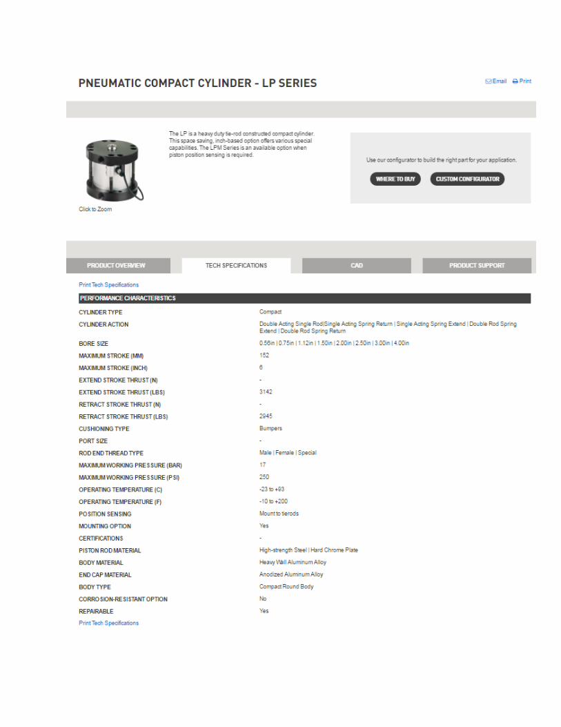
Anderson Metals Corp, Inc
1701 Southern Road
P.O. Box 34200
KANSAS CITY, MO 64120
www.andersonmetals.com
Phone: 1-800-821-5672
Male Connector
129 - Barb x Male Pipe
These products contain lead and are not allowed by Federal Law to be installed for potable water use in the U.S.A. andits territories. WARNING: Furthermore, these products contain a chemical known to the State of California to causecancer, birth defects or other reproductive harm.
Name Temperature Weight Per 1
07001-0202 - 32 to 200 2
07001-0204 - 32 to 200 2
07001-0302 - 32 to 200 3
07001-0304 - 32 to 200 2
07001-0402 - 32 to 200 2
07001-0404 - 32 to 200 4
07001-0406 - 32 to 200 6
07001-0408 - 32 to 200 10
07001-0502 - 32 to 200 3
07001-0504 - 32 to 200 5
07001-0506 - 32 to 200 6
07001-0602 - 32 to 200 4
07001-0604 - 32 to 200 5
07001-0606 - 32 to 200 6
07001-0608 - 32 to 200 7
07001-0612 - 32 to 200 10
07001-0704 - 32 to 200 5
07001-0706 - 32 to 200 6
07001-0804 - 32 to 200 8
07001-0806 - 32 to 200 8
07001-0808 - 32 to 200 11
07001-0812 - 32 to 200 16
07001-1006 - 32 to 200 11
07001-1008 - 32 to 200 12
07001-1012 - 32 to 200 17
07001-1206 - 32 to 200 13
Anderson Metals Corp, Inc 06/02/2016 | Page 1 of 2

Name Temperature Weight Per 1
07001-1208 - 32 to 200 14
07001-1212 - 32 to 200 17
07001-1612 - 32 to 200 21
07001-1616 - 32 to 200 32
07001-2016 - 32 to 200 40
Anderson Metals Corp, Inc 06/02/2016 | Page 2 of 2
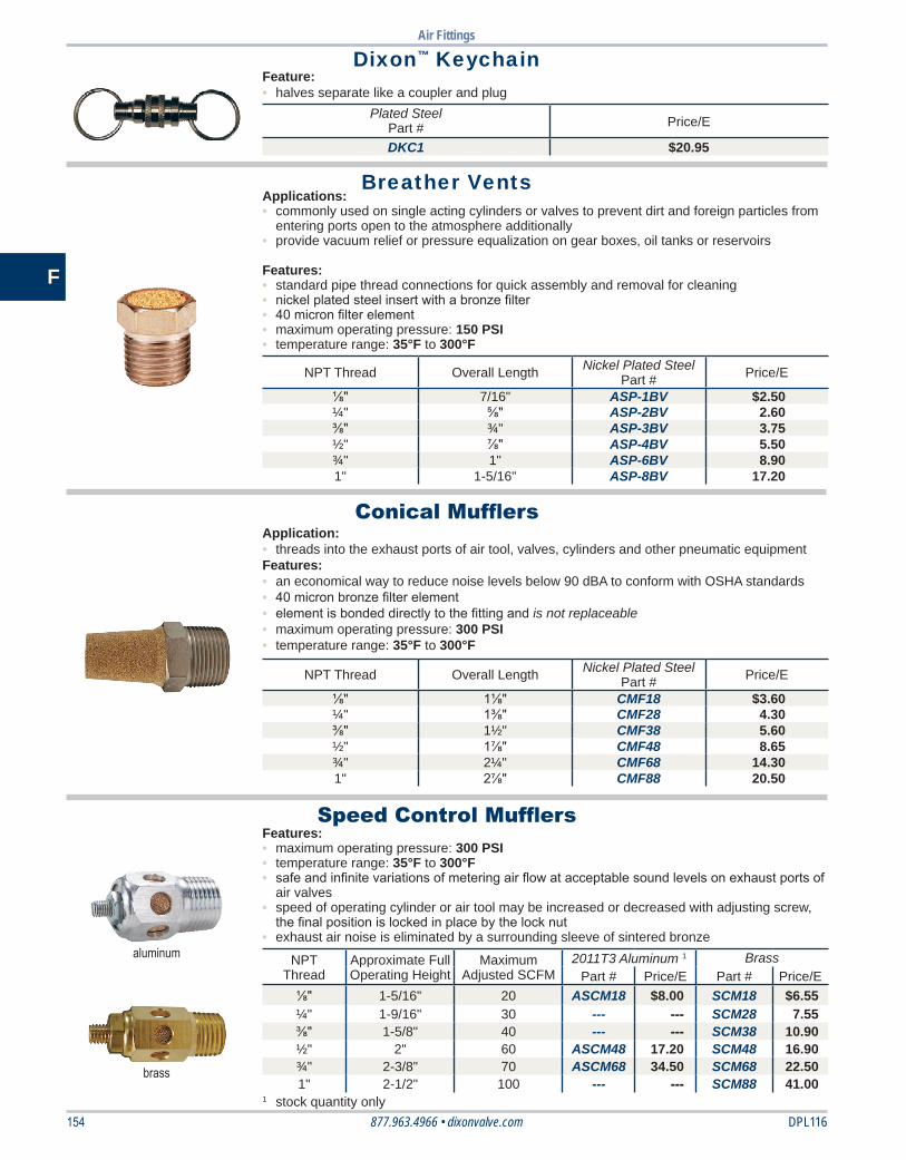
Air Fittings
154 DPL116877.963.4966 • dixonvalve.com
F
Dixon™ Keychain
Breather Vents
Conical Mufflers
Speed Control Mufflers
Feature:• halves separate like a coupler and plug
Plated SteelPart # Price/E
DKC1 $20.95
Applications:• commonly used on single acting cylinders or valves to prevent dirt and foreign particles from
entering ports open to the atmosphere additionally• provide vacuum relief or pressure equalization on gear boxes, oil tanks or reservoirs
Features:• standard pipe thread connections for quick assembly and removal for cleaning• nickel plated steel insert with a bronze filter• 40 micron filter element• maximum operating pressure: 150 PSI• temperature range: 35°F to 300°F
NPT Thread Overall Length Nickel Plated SteelPart # Price/E
⅛" 7/16" ASP-1BV $2.50¼" ⅝" ASP-2BV 2.60⅜" ¾" ASP-3BV 3.75½" ⅞" ASP-4BV 5.50¾" 1" ASP-6BV 8.901" 1-5/16" ASP-8BV 17.20
Application:• threads into the exhaust ports of air tool, valves, cylinders and other pneumatic equipmentFeatures:• an economical way to reduce noise levels below 90 dBA to conform with OSHA standards• 40 micron bronze filter element• element is bonded directly to the fitting and is not replaceable• maximum operating pressure: 300 PSI• temperature range: 35°F to 300°F
NPT Thread Overall Length Nickel Plated SteelPart # Price/E
⅛" 1⅛" CMF18 $3.60¼" 1⅜" CMF28 4.30⅜" 1½" CMF38 5.60½" 1⅞" CMF48 8.65¾" 2¼" CMF68 14.301" 2⅞" CMF88 20.50
brass
aluminum
Features:• maximum operating pressure: 300 PSI• temperature range: 35°F to 300°F• safe and infinite variations of metering air flow at acceptable sound levels on exhaust ports of
air valves• speed of operating cylinder or air tool may be increased or decreased with adjusting screw,
the final position is locked in place by the lock nut• exhaust air noise is eliminated by a surrounding sleeve of sintered bronze
NPTThread
Approximate Full Operating Height
MaximumAdjusted SCFM
2011T3 Aluminum 1 BrassPart # Price/E Part # Price/E
⅛" 1-5/16" 20 ASCM18 $8.00 SCM18 $6.55¼" 1-9/16" 30 --- --- SCM28 7.55⅜" 1-5/8" 40 --- --- SCM38 10.90½" 2" 60 ASCM48 17.20 SCM48 16.90¾" 2-3/8" 70 ASCM68 34.50 SCM68 22.501" 2-1/2" 100 --- --- SCM88 41.00
1 stock quantity only
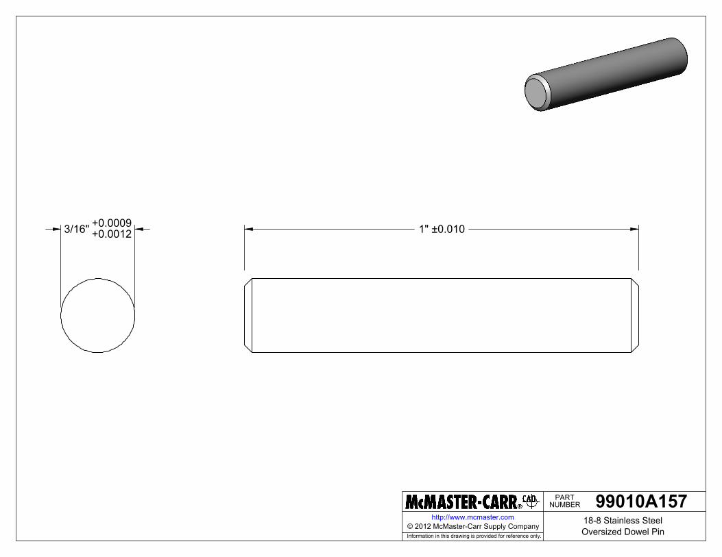
NUMBERPART
Information in this drawing is provided for reference only.
http://www.mcmaster.com
1" ±0.0103/16" +0.0009+0.0012
99010A15718-8 Stainless SteelOversized Dowel Pin© 2012 McMaster-Carr Supply Company
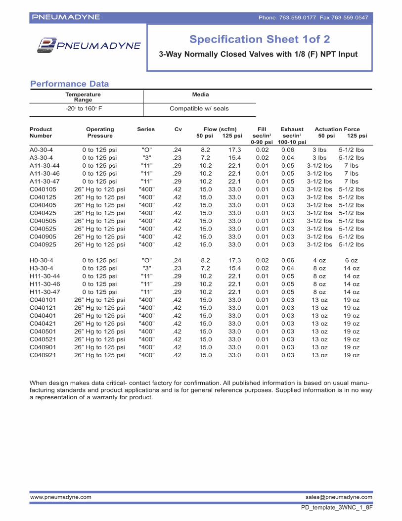
PNEUMADYNE Phone 763-559-0177 Fax 763-559-0547
www.pneumadyne.com [email protected]
Performance DataTemperature
RangeMedia
-20o to 160o F Compatible w/ seals
Specification Sheet 1of 2
3-Way Normally Closed Valves with 1/8 (F) NPT Input
Product Operating Series Cv Flow (scfm) Fill Exhaust Actuation Force
Number Pressure 50 psi 125 psi sec/in3 sec/in3 50 psi 125 psi
0-90 psi 100-10 psi
A0-30-4 0 to 125 psi "O" .24 8.2 17.3 0.02 0.06 3 lbs 5-1/2 lbs
A3-30-4 0 to 125 psi "3" .23 7.2 15.4 0.02 0.04 3 lbs 5-1/2 lbs
A11-30-44 0 to 125 psi "11" .29 10.2 22.1 0.01 0.05 3-1/2 lbs 7 lbs
A11-30-46 0 to 125 psi "11" .29 10.2 22.1 0.01 0.05 3-1/2 lbs 7 lbs
A11-30-47 0 to 125 psi "11" .29 10.2 22.1 0.01 0.05 3-1/2 lbs 7 lbs
C040105 26” Hg to 125 psi "400" .42 15.0 33.0 0.01 0.03 3-1/2 lbs 5-1/2 lbs
C040125 26” Hg to 125 psi "400" .42 15.0 33.0 0.01 0.03 3-1/2 lbs 5-1/2 lbs
C040405 26” Hg to 125 psi "400" .42 15.0 33.0 0.01 0.03 3-1/2 lbs 5-1/2 lbs
C040425 26” Hg to 125 psi "400" .42 15.0 33.0 0.01 0.03 3-1/2 lbs 5-1/2 lbs
C040505 26” Hg to 125 psi "400" .42 15.0 33.0 0.01 0.03 3-1/2 lbs 5-1/2 lbs
C040525 26” Hg to 125 psi "400" .42 15.0 33.0 0.01 0.03 3-1/2 lbs 5-1/2 lbs
C040905 26” Hg to 125 psi "400" .42 15.0 33.0 0.01 0.03 3-1/2 lbs 5-1/2 lbs
C040925 26” Hg to 125 psi "400" .42 15.0 33.0 0.01 0.03 3-1/2 lbs 5-1/2 lbs
H0-30-4 0 to 125 psi "O" .24 8.2 17.3 0.02 0.06 4 oz 6 oz
H3-30-4 0 to 125 psi "3" .23 7.2 15.4 0.02 0.04 8 oz 14 oz
H11-30-44 0 to 125 psi "11" .29 10.2 22.1 0.01 0.05 8 oz 14 oz
H11-30-46 0 to 125 psi "11" .29 10.2 22.1 0.01 0.05 8 oz 14 oz
H11-30-47 0 to 125 psi "11" .29 10.2 22.1 0.01 0.05 8 oz 14 oz
C040101 26” Hg to 125 psi "400" .42 15.0 33.0 0.01 0.03 13 oz 19 oz
C040121 26” Hg to 125 psi "400" .42 15.0 33.0 0.01 0.03 13 oz 19 oz
C040401 26” Hg to 125 psi "400" .42 15.0 33.0 0.01 0.03 13 oz 19 oz
C040421 26” Hg to 125 psi "400" .42 15.0 33.0 0.01 0.03 13 oz 19 oz
C040501 26” Hg to 125 psi "400" .42 15.0 33.0 0.01 0.03 13 oz 19 oz
C040521 26” Hg to 125 psi "400" .42 15.0 33.0 0.01 0.03 13 oz 19 oz
C040901 26” Hg to 125 psi "400" .42 15.0 33.0 0.01 0.03 13 oz 19 oz
C040921 26” Hg to 125 psi "400" .42 15.0 33.0 0.01 0.03 13 oz 19 oz
When design makes data critical- contact factory for confirmation. All published information is based on usual manu-
facturing standards and product applications and is for general reference purposes. Supplied information is in no way
a representation of a warranty for product.
PD_template_3WNC_1_8F
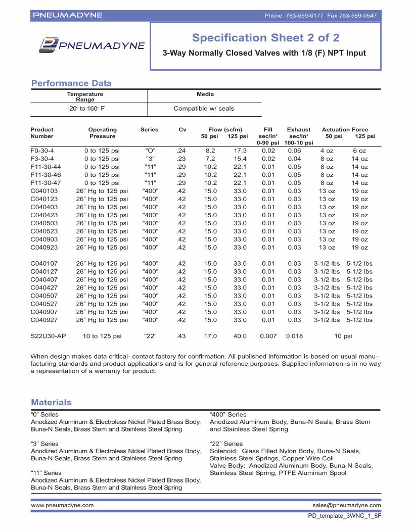
PNEUMADYNE Phone 763-559-0177 Fax 763-559-0547
Materials
“0” Series
Anodized Aluminum & Electroless Nickel Plated Brass Body,
Buna-N Seals, Brass Stem and Stainless Steel Spring
“3” Series
Anodized Aluminum & Electroless Nickel Plated Brass Body,
Buna-N Seals, Brass Stem and Stainless Steel Spring
“11” Series
Anodized Aluminum & Electroless Nickel Plated Brass Body,
Buna-N Seals, Brass Stem and Stainless Steel Spring
“400” Series
Anodized Aluminum Body, Buna-N Seals, Brass Stem
and Stainless Steel Spring
“22” Series
Solenoid: Glass Filled Nylon Body, Buna-N Seals,
Stainless Steel Springs, Copper Wire Coil
Valve Body: Anodized Aluminum Body, Buna-N Seals,
Stainless Steel Spring, PTFE Aluminum Spool
www.pneumadyne.com [email protected]
Performance DataTemperature
RangeMedia
-20o to 160o F Compatible w/ seals
Specification Sheet 2 of 2
3-Way Normally Closed Valves with 1/8 (F) NPT Input
Product Operating Series Cv Flow (scfm) Fill Exhaust Actuation Force
Number Pressure 50 psi 125 psi sec/in3 sec/in3 50 psi 125 psi
0-90 psi 100-10 psi
F0-30-4 0 to 125 psi "O" .24 8.2 17.3 0.02 0.06 4 oz 6 oz
F3-30-4 0 to 125 psi "3" .23 7.2 15.4 0.02 0.04 8 oz 14 oz
F11-30-44 0 to 125 psi "11" .29 10.2 22.1 0.01 0.05 8 oz 14 oz
F11-30-46 0 to 125 psi "11" .29 10.2 22.1 0.01 0.05 8 oz 14 oz
F11-30-47 0 to 125 psi "11" .29 10.2 22.1 0.01 0.05 8 oz 14 oz
C040103 26” Hg to 125 psi "400" .42 15.0 33.0 0.01 0.03 13 oz 19 oz
C040123 26” Hg to 125 psi "400" .42 15.0 33.0 0.01 0.03 13 oz 19 oz
C040403 26” Hg to 125 psi "400" .42 15.0 33.0 0.01 0.03 13 oz 19 oz
C040423 26” Hg to 125 psi "400" .42 15.0 33.0 0.01 0.03 13 oz 19 oz
C040503 26” Hg to 125 psi "400" .42 15.0 33.0 0.01 0.03 13 oz 19 oz
C040523 26” Hg to 125 psi "400" .42 15.0 33.0 0.01 0.03 13 oz 19 oz
C040903 26” Hg to 125 psi "400" .42 15.0 33.0 0.01 0.03 13 oz 19 oz
C040923 26” Hg to 125 psi "400" .42 15.0 33.0 0.01 0.03 13 oz 19 oz
C040107 26” Hg to 125 psi "400" .42 15.0 33.0 0.01 0.03 3-1/2 lbs 5-1/2 lbs
C040127 26” Hg to 125 psi "400" .42 15.0 33.0 0.01 0.03 3-1/2 lbs 5-1/2 lbs
C040407 26” Hg to 125 psi "400" .42 15.0 33.0 0.01 0.03 3-1/2 lbs 5-1/2 lbs
C040427 26” Hg to 125 psi "400" .42 15.0 33.0 0.01 0.03 3-1/2 lbs 5-1/2 lbs
C040507 26” Hg to 125 psi "400" .42 15.0 33.0 0.01 0.03 3-1/2 lbs 5-1/2 lbs
C040527 26” Hg to 125 psi "400" .42 15.0 33.0 0.01 0.03 3-1/2 lbs 5-1/2 lbs
C040907 26” Hg to 125 psi "400" .42 15.0 33.0 0.01 0.03 3-1/2 lbs 5-1/2 lbs
C040927 26” Hg to 125 psi "400" .42 15.0 33.0 0.01 0.03 3-1/2 lbs 5-1/2 lbs
S22U30-AP 10 to 125 psi "22" .43 17.0 40.0 0.007 0.018 10 psi
When design makes data critical- contact factory for confirmation. All published information is based on usual manu-
facturing standards and product applications and is for general reference purposes. Supplied information is in no way
a representation of a warranty for product.
PD_template_3WNC_1_8F
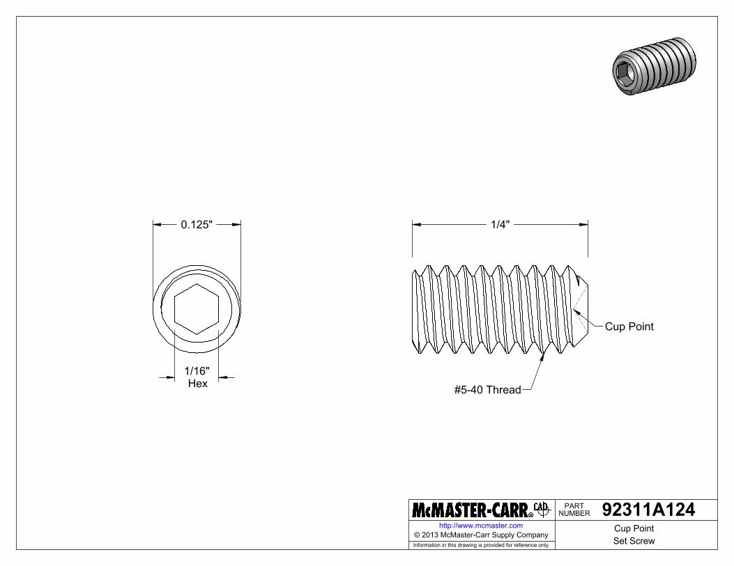
NUMBERPART
Information in this drawing is provided for reference only.
http://www.mcmaster.com
1/16"Hex
0.125" 1/4"
Cup Point
#5-40 Thread
92311A124Cup PointSet Screw
© 2013 McMaster-Carr Supply Company
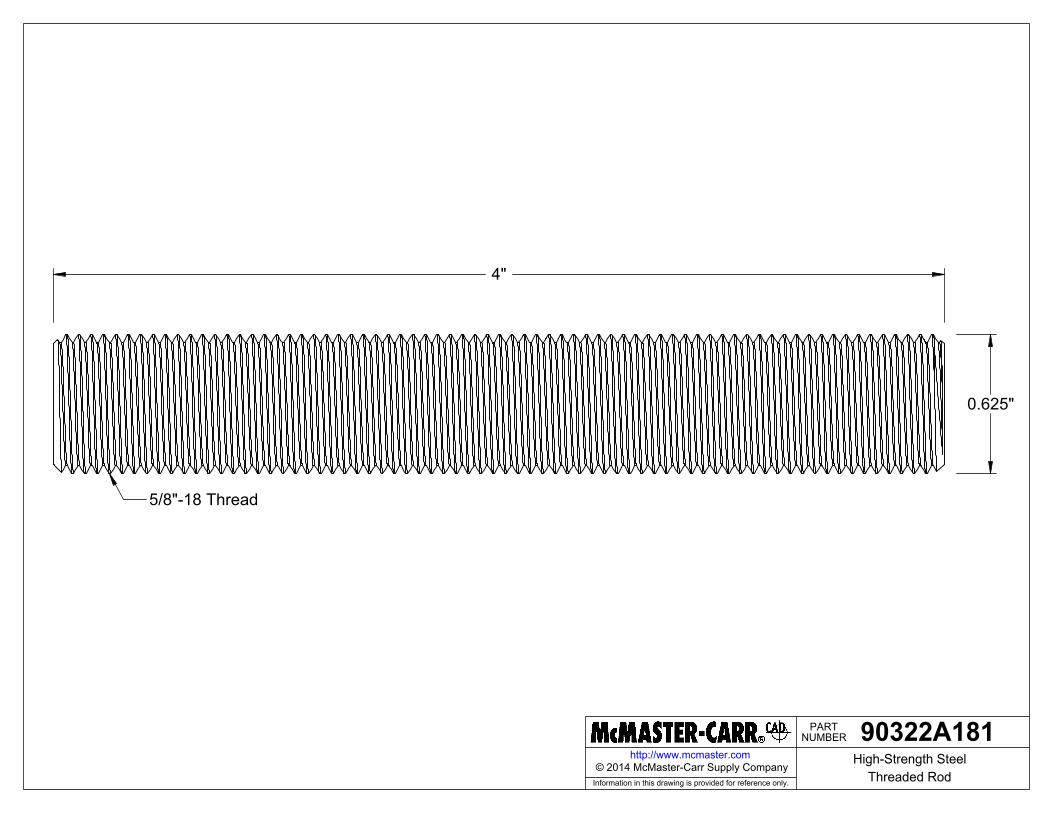
NUMBERPART
Information in this drawing is provided for reference only.
http://www.mcmaster.com
0.625"
4"
5/8"-18 Thread
90322A181High-Strength Steel
Threaded Rod© 2014 McMaster-Carr Supply Company
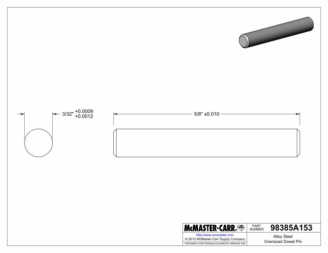
NUMBERPART
Information in this drawing is provided for reference only.
http://www.mcmaster.com
5/8" ±0.0103/32" +0.0009+0.0012
98385A153Alloy Steel
Oversized Dowel Pin© 2012 McMaster-Carr Supply Company
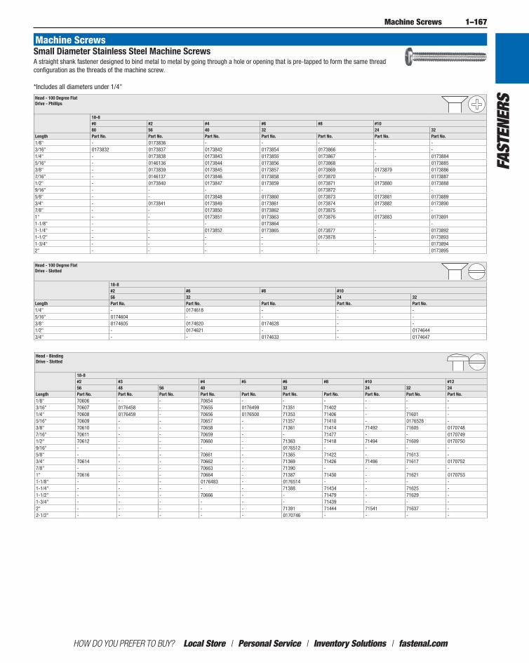
1–167
HOW DO YOU PREFER TO BUY? Local Store / Personal Service / Inventory Solutions / fastenal.com
Fast
ener
s
Machine Screws
Machine ScrewsSmall Diameter Stainless Steel Machine ScrewsA straight shank fastener designed to bind metal to metal by going through a hole or opening that is pre-tapped to form the same thread configuration as the threads of the machine screw. *Includes all diameters under 1/4"
Head - 100 Degree Flat Drive - Phillips
18-8#0 #2 #4 #6 #8 #1080 56 40 32 24 32
Length Part No. Part No. Part No. Part No. Part No. Part No. Part No.1/8" - 0173836 - - - - -3/16" 0173832 0173837 0173842 0173854 0173866 - -1/4" - 0173838 0173843 0173855 0173867 - 01738845/16" - 0146136 0173844 0173856 0173868 - 01738853/8" - 0173839 0173845 0173857 0173869 0173879 01738867/16" - 0146137 0173846 0173858 0173870 - 01738871/2" - 0173840 0173847 0173859 0173871 0173880 01738889/16" - - - - 0173872 - -5/8" - - 0173848 0173860 0173873 0173881 01738893/4" - 0173841 0173849 0173861 0173874 0173882 01738907/8" - - 0173850 0173862 0173875 - -1" - - 0173851 0173863 0173876 0173883 01738911-1/8" - - - 0173864 - - -1-1/4" - - 0173852 0173865 0173877 - 01738921-1/2" - - - - 0173878 - 01738931-3/4" - - - - - - 01738942" - - - - - - 0173895
Head - 100 Degree Flat Drive - Slotted
18-8#2 #6 #8 #1056 32 24 32
Length Part No. Part No. Part No. Part No. Part No.1/4" - 0174618 - - -5/16" 0174604 - - - -3/8" 0174605 0174620 0174628 - -1/2" - 0174621 - - 01746443/4" - - 0174633 - 0174647
Head - Binding Drive - Slotted
18-8#2 #3 #4 #5 #6 #8 #10 #1256 48 56 40 32 24 32 24
Length Part No. Part No. Part No. Part No. Part No. Part No. Part No. Part No. Part No. Part No.1/8" 70606 - - 70654 - - - - - -3/16" 70607 0176458 - 70655 0176499 71351 71402 - - -1/4" 70608 0176459 - 70656 0176500 71353 71406 - 71601 -5/16" 70609 - - 70657 - 71357 71410 - 0176528 -3/8" 70610 - - 70658 - 71361 71414 71492 71605 01707487/16" 70611 - - 70659 - - 71477 - - 01707491/2" 70612 - - 70660 - 71363 71418 71494 71609 01707509/16" - - - - - 0176512 - - - -5/8" - - - 70661 - 71365 71422 - 71613 -3/4" 70614 - - 70662 - 71369 71426 71496 71617 01707527/8" - - - 70663 - 71390 - - - -1" 70616 - - 70664 - 71387 71430 - 71621 01707531-1/8" - - - 0176483 - 0176514 - - - -1-1/4" - - - - - 71388 71434 - 71625 -1-1/2" - - - 70666 - - 71479 - 71629 -1-3/4" - - - - - - 71439 - - -2" - - - - - 71391 71444 71541 71637 -2-1/2" - - - - - 0170746 - - - -
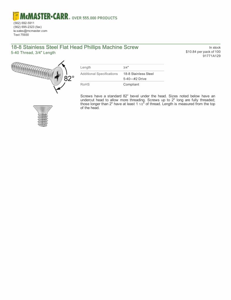
188 Stainless Steel Flat Head Phillips Machine Screw540 Thread, 3/4" Length
In stock$10.84 per pack of 100
91771A129
Length 3/4"
Additional Specifications 188 Stainless Steel540—#2 Drive
RoHS Compliant
Screws have a standard 82° bevel under the head. Sizes noted below have anundercut head to allow more threading. Screws up to 2" long are fully threaded;those longer than 2" have at least 1 1/2" of thread. Length is measured from the topof the head.
(562) 6925911(562) 6952323 (fax)[email protected] 75930
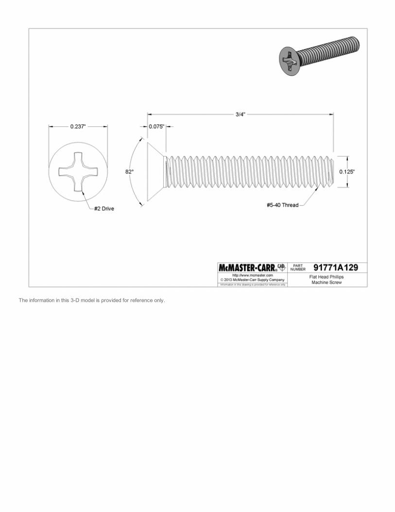
The information in this 3D model is provided for reference only.

188 Stainless Steel Flat Head Phillips Machine Screw540 Thread, 3/8" Length
In stock$6.83 per pack of 100
91771A126
Length 3/8"
Additional Specifications 188 Stainless Steel540—#2 Drive
RoHS Compliant
Screws have a standard 82° bevel under the head. Sizes noted below have anundercut head to allow more threading. Screws up to 2" long are fully threaded;those longer than 2" have at least 1 1/2" of thread. Length is measured from the topof the head.
(562) 6925911(562) 6952323 (fax)[email protected] 75930
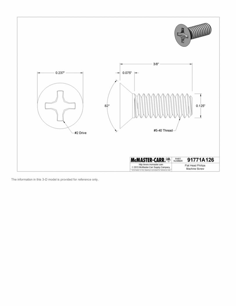
The information in this 3D model is provided for reference only.
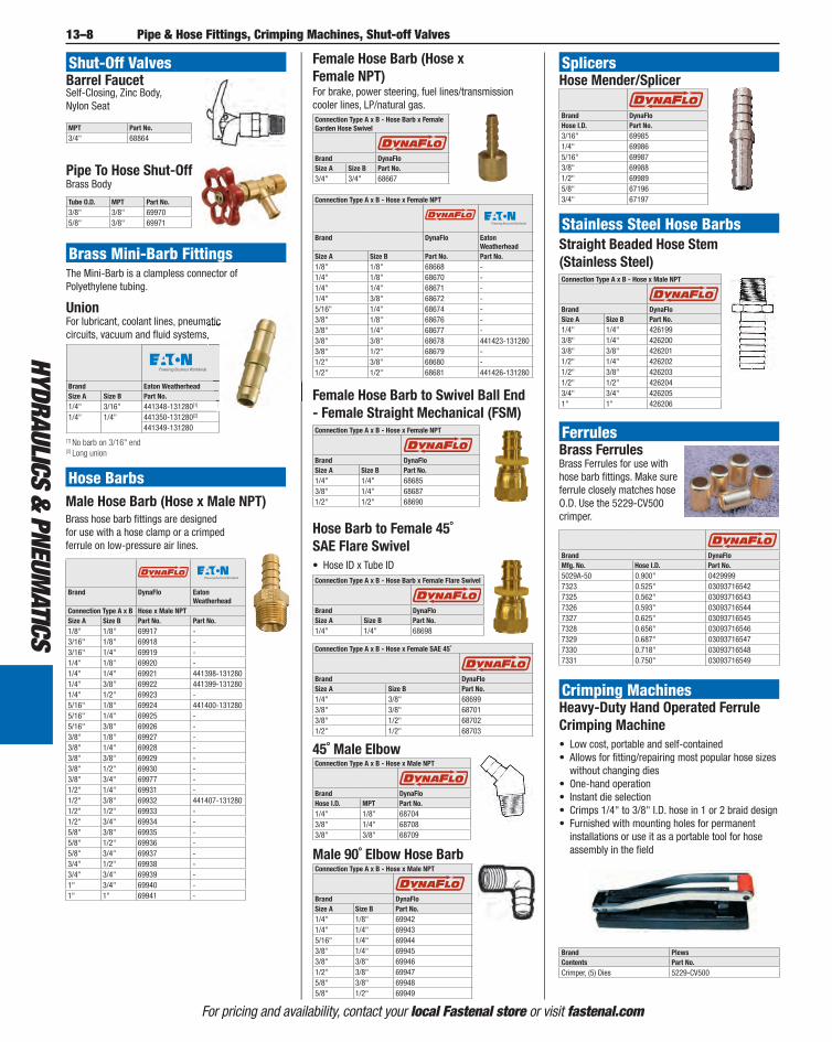
13–8
HYdrauLIcS & PneumaTIcS
For pricing and availability, contact your local Fastenal store or visit fastenal.com
Pipe & Hose Fittings, Crimping Machines, Shut-off Valves
Shut-Off ValvesBarrel FaucetSelf-Closing, Zinc Body, Nylon Seat
MPT Part No.3/4" 68864
Pipe To Hose Shut-OffBrass Body
Tube O.D. MPT Part No.3/8" 3/8" 699705/8" 3/8" 69971
Brass Mini-Barb FittingsThe Mini-Barb is a clampless connector of Polyethylene tubing.
UnionFor lubricant, coolant lines, pneumatic circuits, vacuum and fl uid systems.
Brand Eaton WeatherheadSize A Size B Part No.1/4" 3/16" 441348-131280[1]
1/4" 1/4" 441350-131280[2]
441349-131280
For lubricant, coolant lines, pneumatic circuits, vacuum and fl uid systems.
[1] No barb on 3/16" end[2] Long union
Hose BarbsMale Hose Barb (Hose x Male NPT)Brass hose barb fi ttings are designed for use with a hose clamp or a crimped ferrule on low-pressure air lines.
Brand DynaFlo Eaton Weatherhead
Connection Type A x B Hose x Male NPTSize A Size B Part No. Part No.1/8" 1/8" 69917 -3/16" 1/8" 69918 -3/16" 1/4" 69919 -1/4" 1/8" 69920 -1/4" 1/4" 69921 441398-1312801/4" 3/8" 69922 441399-1312801/4" 1/2" 69923 -5/16" 1/8" 69924 441400-1312805/16" 1/4" 69925 -5/16" 3/8" 69926 -3/8" 1/8" 69927 -3/8" 1/4" 69928 -3/8" 3/8" 69929 -3/8" 1/2" 69930 -3/8" 3/4" 69977 -1/2" 1/4" 69931 -1/2" 3/8" 69932 441407-1312801/2" 1/2" 69933 -1/2" 3/4" 69934 -5/8" 3/8" 69935 -5/8" 1/2" 69936 -5/8" 3/4" 69937 -3/4" 1/2" 69938 -3/4" 3/4" 69939 -1" 3/4" 69940 -1" 1" 69941 -
Female Hose Barb (Hose x Female NPT)
Female Hose Barb to Swivel Ball End - Female Straight Mechanical (FSM)Connection Type A x B - Hose x Female NPT
Brand DynaFloSize A Size B Part No.1/4" 1/4" 686853/8" 1/4" 686871/2" 1/2" 68690
For brake, power steering, fuel lines/transmission cooler lines, LP/natural gas.Connection Type A x B - Hose Barb x Female Garden Hose Swivel
Brand DynaFloSize A Size B Part No.3/4" 3/4" 68667
Connection Type A x B - Hose x Female NPT
Brand DynaFlo Eaton Weatherhead
Size A Size B Part No. Part No.1/8" 1/8" 68668 -1/4" 1/8" 68670 -1/4" 1/4" 68671 -1/4" 3/8" 68672 -5/16" 1/4" 68674 -3/8" 1/8" 68676 -3/8" 1/4" 68677 -3/8" 3/8" 68678 441423-1312803/8" 1/2" 68679 -1/2" 3/8" 68680 -1/2" 1/2" 68681 441426-131280
Hose Barb to Female 45˚ SAE Flare Swivel
• Hose ID x Tube IDConnection Type A x B - Hose Barb x Female Flare Swivel
Brand DynaFloSize A Size B Part No.1/4" 1/4" 68698
Connection Type A x B - Hose x Female SAE 45˚
Brand DynaFloSize A Size B Part No.1/4" 3/8" 686993/8" 3/8" 687013/8" 1/2" 687021/2" 1/2" 68703
45˚ Male ElbowConnection Type A x B - Hose x Male NPT
Brand DynaFloHose I.D. MPT Part No.1/4" 1/8" 687043/8" 1/4" 687083/8" 3/8" 68709
Male 90˚ Elbow Hose BarbConnection Type A x B - Hose x Male NPT
Brand DynaFloSize A Size B Part No.1/4" 1/8" 699421/4" 1/4" 699435/16" 1/4" 699443/8" 1/4" 699453/8" 3/8" 699461/2" 3/8" 699475/8" 3/8" 699485/8" 1/2" 69949
SplicersHose Mender/Splicer
Brand DynaFloHose I.D. Part No.3/16" 699851/4" 699865/16" 699873/8" 699881/2" 699895/8" 671963/4" 67197
Stainless Steel Hose BarbsStraight Beaded Hose Stem (Stainless Steel)Connection Type A x B - Hose x Male NPT
Brand DynaFloSize A Size B Part No.1/4" 1/4" 4261993/8" 1/4" 4262003/8" 3/8" 4262011/2" 1/4" 4262021/2" 3/8" 4262031/2" 1/2" 4262043/4" 3/4" 4262051" 1" 426206
FerrulesBrass FerrulesBrass Ferrules for use with hose barb fi ttings. Make sure ferrule closely matches hose O.D. Use the 5229-CV500 crimper.
Brand DynaFloMfg. No. Hose I.D. Part No.5029A-50 0.900" 04299997323 0.525" 030937165427325 0.562" 030937165437326 0.593" 030937165447327 0.625" 030937165457328 0.656" 030937165467329 0.687" 030937165477330 0.718" 030937165487331 0.750" 03093716549
Crimping MachinesHeavy-Duty Hand Operated Ferrule Crimping Machine
• Low cost, portable and self-contained • Allows for fi tting/repairing most popular hose sizes without changing dies
• One-hand operation • Instant die selection • Crimps 1/4" to 3/8" I.D. hose in 1 or 2 braid design • Furnished with mounting holes for permanent installations or use it as a portable tool for hose assembly in the fi eld
Brand PlewsContents Part No.Crimper, (5) Dies 5229-CV500
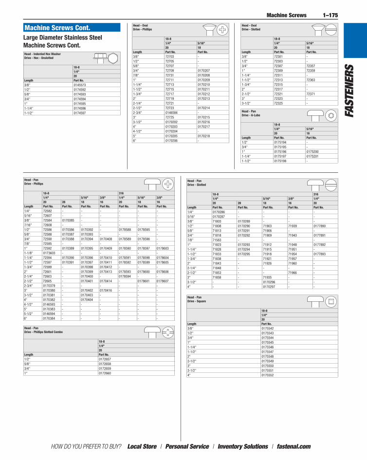
1–175
HOW DO YOU PREFER TO BUY? Local Store / Personal Service / Inventory Solutions / fastenal.com
Fast
ener
s
Machine Screws
Head - Indented Hex Washer Drive - Hex - Unslotted
18-81/4"20
Length Part No.3/8" 01455731/2" 01745925/8" 01745933/4" 01745941" 01745951-1/4" 01745961-1/2" 0174597
Head - Oval Drive - Phillips
18-81/4" 5/16"20 18
Length Part No. Part No.3/8" 72703 -1/2" 72705 -5/8" 72707 -3/4" 72709 01702077/8" 72731 01702081" 72711 01702091-1/4" 72713 01702101-1/2" 72715 01702111-3/4" 72717 01702122" 72719 01702132-1/4" 72721 -2-1/2" 72723 01702142-3/4" 0146584 -3" 72725 01702153-1/2" 0170202 01702164" 0170203 01702174-1/2" 0170204 -5" 0170205 01702186" 0170206 -
Head - Oval Drive - Slotted
18-81/4" 5/16"20 18
Length Part No. Part No.3/8" 72301 -1/2" 72303 -3/4" 72307 723571" 72309 723591-1/4" 72311 -1-1/2" 72313 723631-3/4" 72315 -2" 72317 -2-1/2" 72321 723713" 72323 -3-1/2" 72325 -
Large Diameter Stainless Steel Machine Screws Cont.
Machine Screws Cont.
Head - Pan Drive - 6-Lobe
18-81/4" 5/16"20 18
Length Part No. Part No.1/2" 0175194 -3/4" 0175195 -1" 0175196 01752001-1/4" 0175197 01752011-1/2" 0175198 -
Head - Pan Drive - Phillips
18-8 3161/4" 5/16" 3/8" 1/4" 5/16" 3/8"20 28 18 16 20 18 16
Length Part No. Part No. Part No. Part No. Part No. Part No. Part No.1/4" 72582 - - - - - -5/16" 72607 - - - - - -3/8" 72584 0170385 - - - - -7/16" 72608 - - - - - -1/2" 72586 0170386 0170392 - 0178588 0178595 -5/8" 72588 0170387 0170393 - - - -3/4" 72590 0170388 0170394 0170408 0178589 0178596 -7/8" 72595 - - - - - -1" 72592 0170389 0170395 0170409 0178590 0178597 01786031-1/8" 0173603 - - - - - -1-1/4" 72594 0170390 0170396 0170410 0178591 0178598 01786041-1/2" 72597 0170391 0170397 0170411 0178592 0178599 01786051-3/4" 72599 - 0170398 0170412 - - -2" 72601 - 0170399 0170413 0178593 0178600 01786062-1/4" 72603 - 0170400 - 0178594 - -2-1/2" 72605 - 0170401 0170414 - 0178601 01786072-3/4" 0170379 - - - - - -3" 0170380 - 0170402 0170416 - - -3-1/2" 0170381 - 0170403 - - - -4" 0170382 - 0170404 - - - -4-1/2" 0146593 - - - - - -5" 0170383 - - - - - -5-1/2" 0146594 - - - - - -6" 0170384 - - - - - -
Head - Pan Drive - Phillips Slotted Combo
18-81/4"20
Length Part No.1/2" 01726575/8" 01726583/4" 01726591" 0172660
Head - Pan Drive - Slotted
18-8 3161/4" 5/16" 3/8" 1/4"20 28 18 16 20
Length Part No. Part No. Part No. Part No. Part No.1/4" 0170286 - - - -5/16" 0170287 - - - -3/8" 71803 0170289 - - -1/2" 71808 0170290 71903 71939 01778905/8" 71813 0170291 71906 - -3/4" 71818 0170292 71909 71943 01778917/8" 71563 - - - -1" 71823 0170293 71912 71948 01778921-1/4" 71828 0170294 71915 71951 -1-1/2" 71833 0170295 71918 71954 01778931-3/4" 71838 - 71921 71957 -2" 71843 - 71926 71960 -2-1/4" 71848 - - - -2-1/2" 71853 - - 71966 -3" 71858 - 71935 - -3-1/2" - - 0170296 - -4" - - 0170297 - -
Head - Pan Drive - Square
18-81/4"20
Length Part No.3/8" 01755421/2" 01755433/4" 01755441" 01755451-1/4" 01755461-1/2" 01755472" 01755482-1/2" 01755493" 01755503-1/2" 01755514" 0175552
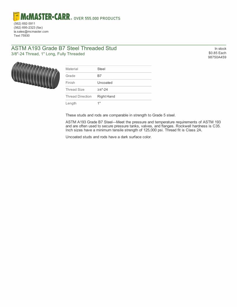
ASTM A193 Grade B7 Steel Threaded Stud3/8"24 Thread, 1" Long, Fully Threaded
In stock$0.85 Each98750A459
Material Steel
Grade B7
Finish Uncoated
Thread Size 3/8"24
Thread Direction Right Hand
Length 1"
These studs and rods are comparable in strength to Grade 5 steel.
ASTM A193 Grade B7 Steel—Meet the pressure and temperature requirements of ASTM 193and are often used to secure pressure tanks, valves, and flanges. Rockwell hardness is C35.Inch sizes have a minimum tensile strength of 125,000 psi. Thread fit is Class 2A.
Uncoated studs and rods have a dark surface color.
(562) 6925911(562) 6952323 (fax)[email protected] 75930
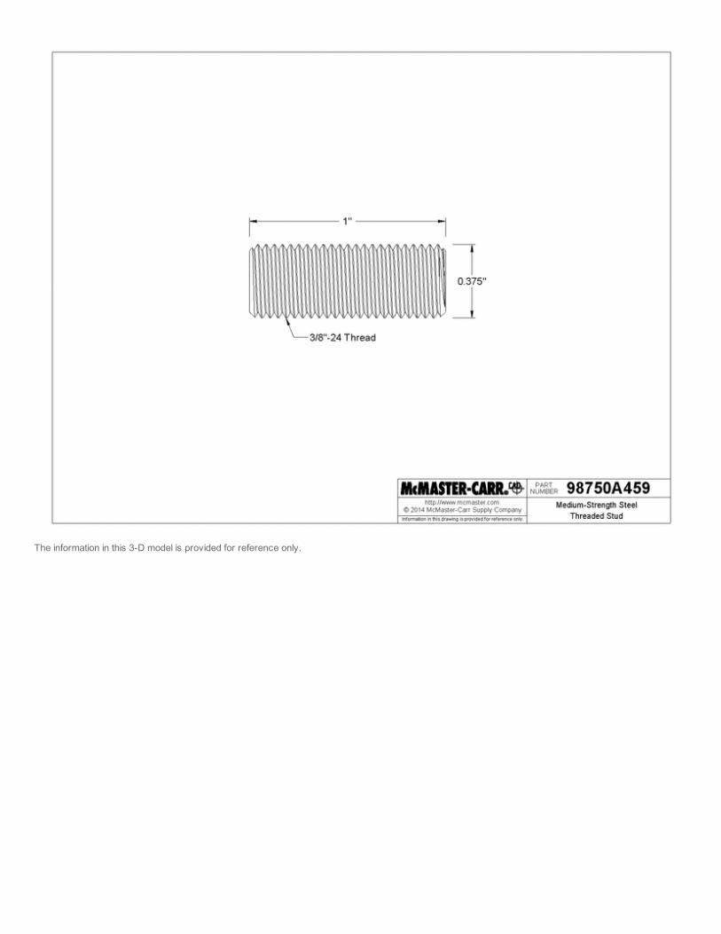
The information in this 3D model is provided for reference only.
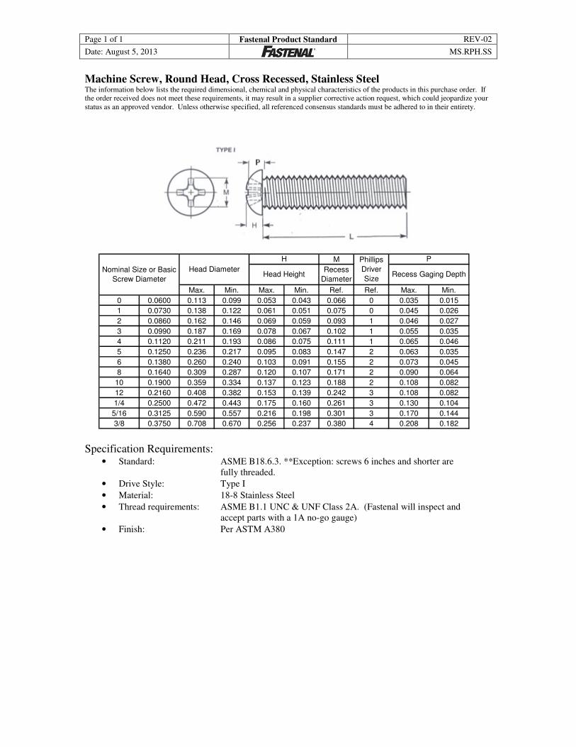
Page 1 of 1 Fastenal Product Standard REV-02
Date: August 5, 2013
MS.RPH.SS
Machine Screw, Round Head, Cross Recessed, Stainless Steel The information below lists the required dimensional, chemical and physical characteristics of the products in this purchase order. If
the order received does not meet these requirements, it may result in a supplier corrective action request, which could jeopardize your
status as an approved vendor. Unless otherwise specified, all referenced consensus standards must be adhered to in their entirety.
M
Max. Min. Max. Min. Ref. Ref. Max. Min.
0 0.0600 0.113 0.099 0.053 0.043 0.066 0 0.035 0.015
1 0.0730 0.138 0.122 0.061 0.051 0.075 0 0.045 0.026
2 0.0860 0.162 0.146 0.069 0.059 0.093 1 0.046 0.027
3 0.0990 0.187 0.169 0.078 0.067 0.102 1 0.055 0.035
4 0.1120 0.211 0.193 0.086 0.075 0.111 1 0.065 0.046
5 0.1250 0.236 0.217 0.095 0.083 0.147 2 0.063 0.035
6 0.1380 0.260 0.240 0.103 0.091 0.155 2 0.073 0.045
8 0.1640 0.309 0.287 0.120 0.107 0.171 2 0.090 0.064
10 0.1900 0.359 0.334 0.137 0.123 0.188 2 0.108 0.082
12 0.2160 0.408 0.382 0.153 0.139 0.242 3 0.108 0.082
1/4 0.2500 0.472 0.443 0.175 0.160 0.261 3 0.130 0.104
5/16 0.3125 0.590 0.557 0.216 0.198 0.301 3 0.170 0.144
3/8 0.3750 0.708 0.670 0.256 0.237 0.380 4 0.208 0.182
P
Recess Gaging Depth
Phillips
Driver
Size
Recess
Diameter
Nominal Size or Basic
Screw DiameterHead Height
H
Head Diameter
Specification Requirements: • Standard: ASME B18.6.3. **Exception: screws 6 inches and shorter are
fully threaded.
• Drive Style: Type I
• Material: 18-8 Stainless Steel
• Thread requirements: ASME B1.1 UNC & UNF Class 2A. (Fastenal will inspect and
accept parts with a 1A no-go gauge)
• Finish: Per ASTM A380
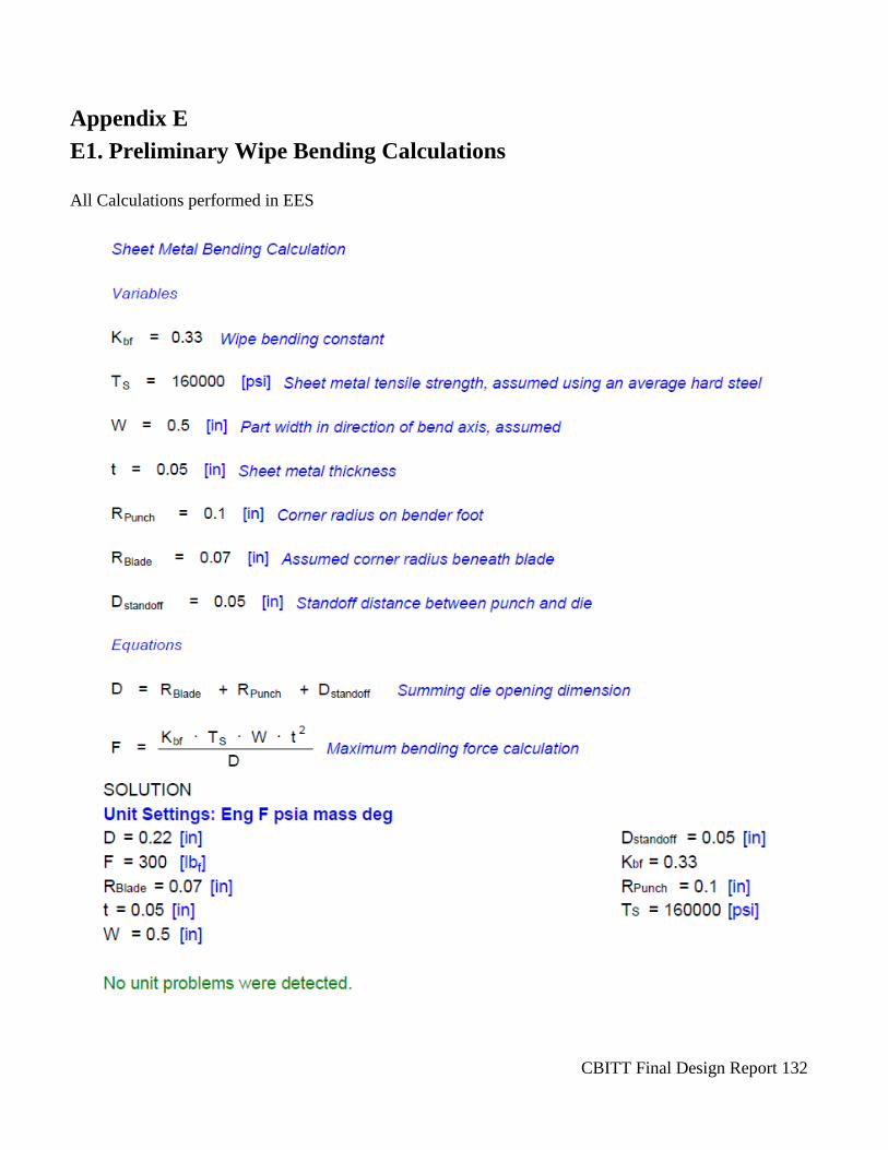
CBITT Final Design Report 132
Appendix E
E1. Preliminary Wipe Bending Calculations
All Calculations performed in EES
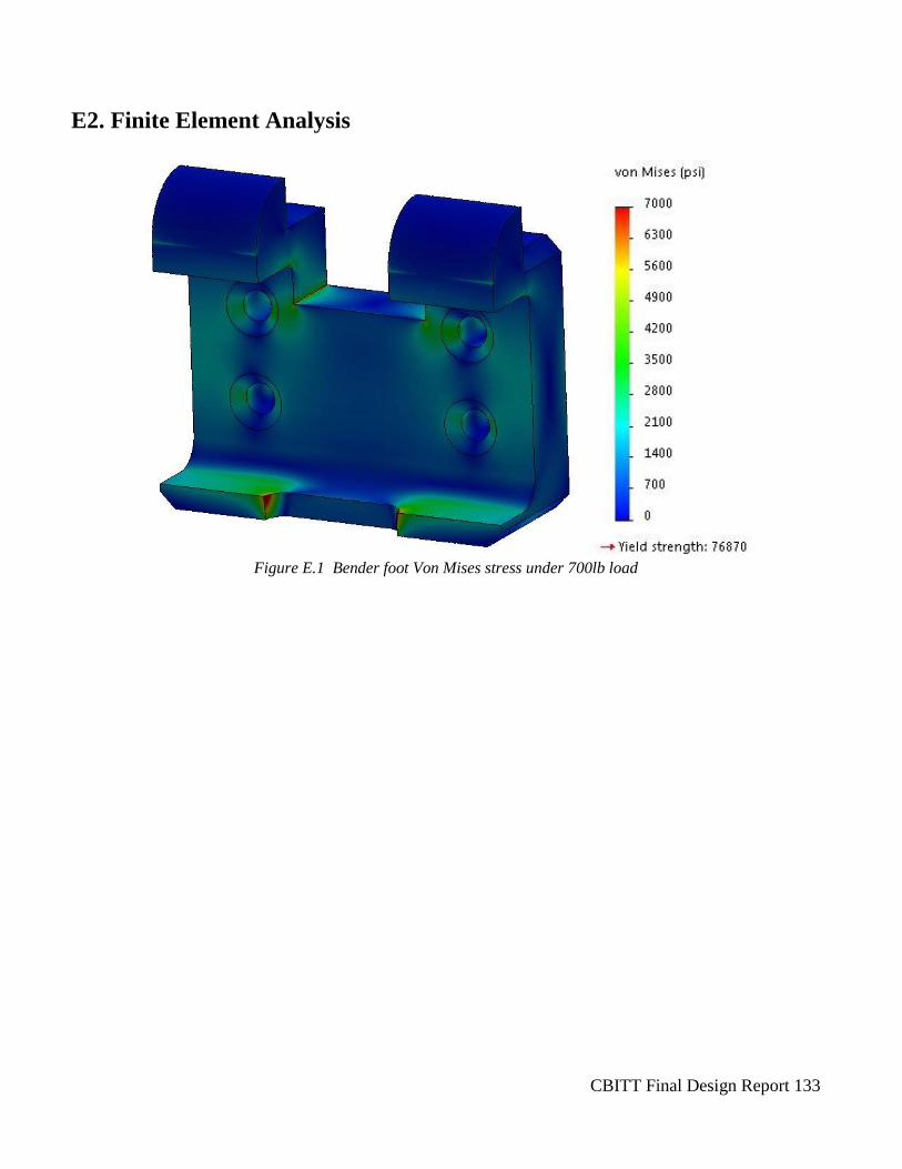
CBITT Final Design Report 133
E2. Finite Element Analysis
Figure E.1 Bender foot Von Mises stress under 700lb load
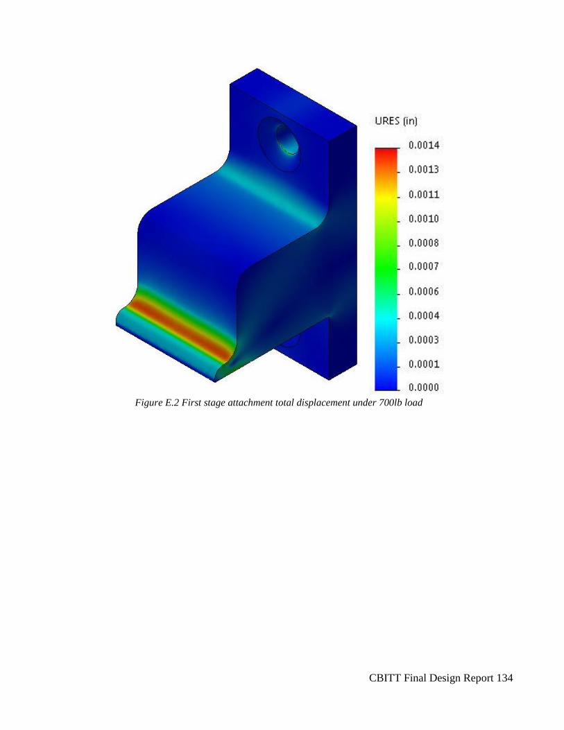
CBITT Final Design Report 134
Figure E.2 First stage attachment total displacement under 700lb load
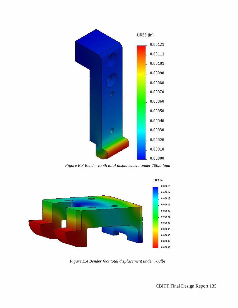
CBITT Final Design Report 135
Figure E.3 Bender tooth total displacement under 700lb load
Figure E.4 Bender foot total displacement under 700lbs
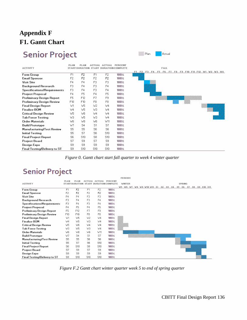
CBITT Final Design Report 136
Appendix F
F1. Gantt Chart
Figure 0. Gantt chart start fall quarter to week 4 winter quarter
Figure F.2 Gantt chart winter quarter week 5 to end of spring quarter
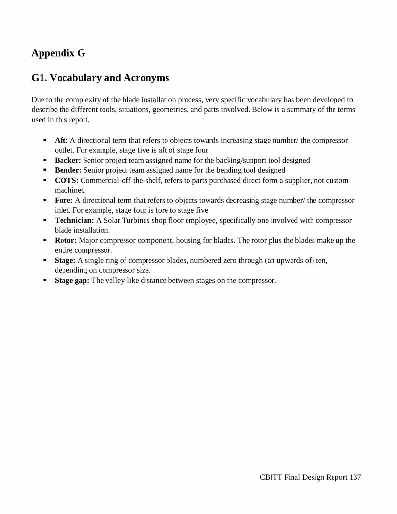
CBITT Final Design Report 137
Appendix G
G1. Vocabulary and Acronyms
Due to the complexity of the blade installation process, very specific vocabulary has been developed to
describe the different tools, situations, geometries, and parts involved. Below is a summary of the terms
used in this report.
Aft: A directional term that refers to objects towards increasing stage number/ the compressor
outlet. For example, stage five is aft of stage four.
Backer: Senior project team assigned name for the backing/support tool designed
Bender: Senior project team assigned name for the bending tool designed
COTS: Commercial-off-the-shelf, refers to parts purchased direct form a supplier, not custom
machined
Fore: A directional term that refers to objects towards decreasing stage number/ the compressor
inlet. For example, stage four is fore to stage five.
Technician: A Solar Turbines shop floor employee, specifically one involved with compressor
blade installation.
Rotor: Major compressor component, housing for blades. The rotor plus the blades make up the
entire compressor.
Stage: A single ring of compressor blades, numbered zero through (an upwards of) ten,
depending on compressor size.
Stage gap: The valley-like distance between stages on the compressor.

CBITT Final Design Report 138
G2. Hazard Identification Checklist
SENIOR PROJECT CRITICAL DESIGN HAZARD IDENTIFICATION CHECKLIST
Team: 20–Compressor Blade Installation Tool Team Advisor: Christoph Maurer
Y N Do any parts of the design create hazardous revolving, reciprocating, running, shearing,
punching, pressing, squeezing, drawing, cutting, rolling, mixing or similar action, including
pinch points and sheer points adequately guarded?
Does any part of the design undergo high accelerations/decelerations that are exposed to
the user?
Does the system have any large moving masses or large forces that can contact the user?
Does the system produce a projectile?
Can the system to fall under gravity creating injury?
Is the user exposed to overhanging weights as part of the design?
Does the system have any sharp edges exposed?
Are there any ungrounded electrical systems in the design?
Are there any large capacity batteries or is there electrical voltage in the system above 40 V
either AC or DC?
Is there be any stored energy in the system such as batteries, flywheels, hanging weights or
pressurized fluids when the system is either on or off?
Are there any explosive or flammable liquids, gases, dust, or fuel in the system?
Is the user of the design required to exert any abnormal effort and/or assume an abnormal
physical posture during the use of the design?
Are there any materials known to be hazardous to humans involved in either the design or
the manufacturing of the design?
Will the system generate high levels of noise?
Will the product be subjected to extreme environmental conditions such as fog, humidity,
cold, high temperatures, etc. that could create an unsafe condition?
Is it easy to use the system unsafely?
Are there any other potential hazards not listed above? If yes, please explain on the back of
this checklist.
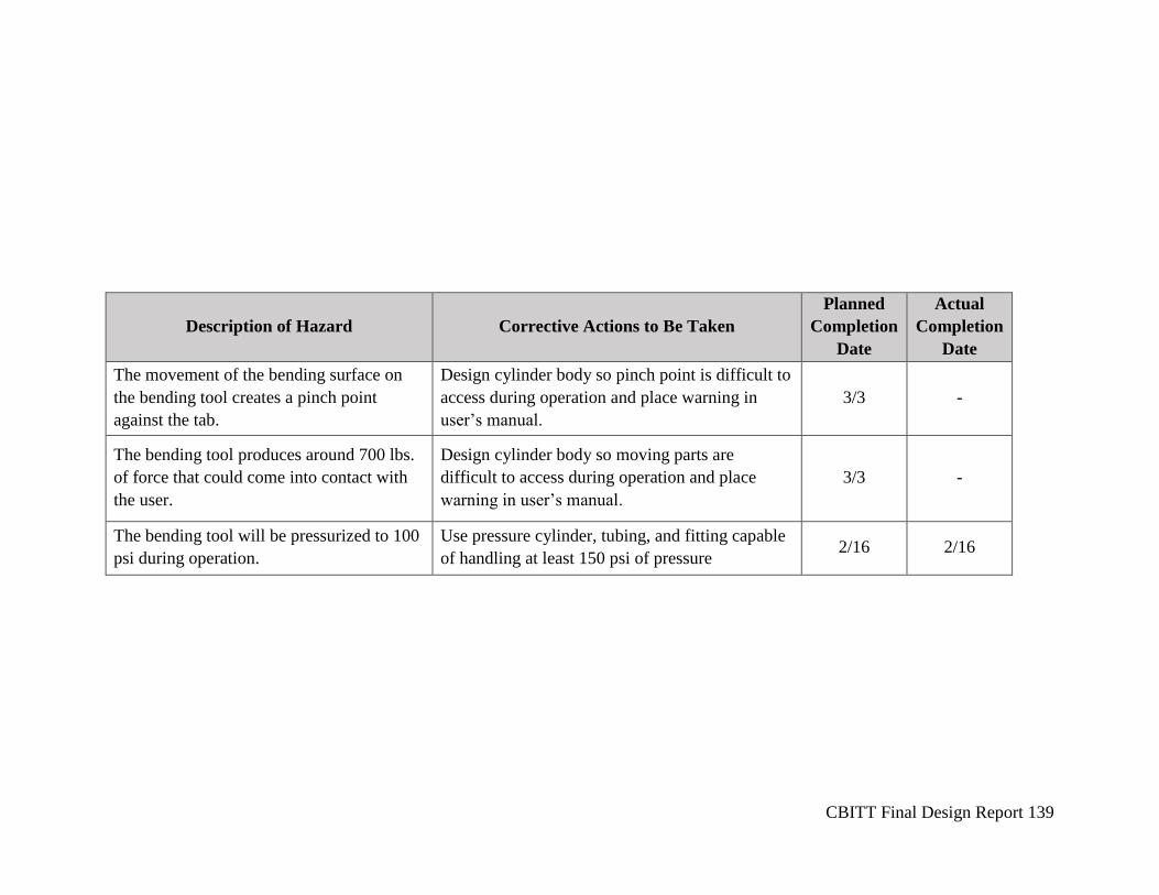
CBITT Final Design Report 139
Description of Hazard Corrective Actions to Be Taken
Planned
Completion
Date
Actual
Completion
Date
The movement of the bending surface on
the bending tool creates a pinch point
against the tab.
Design cylinder body so pinch point is difficult to
access during operation and place warning in
user’s manual.
3/3 -
The bending tool produces around 700 lbs.
of force that could come into contact with
the user.
Design cylinder body so moving parts are
difficult to access during operation and place
warning in user’s manual.
3/3 -
The bending tool will be pressurized to 100
psi during operation.
Use pressure cylinder, tubing, and fitting capable
of handling at least 150 psi of pressure 2/16 2/16
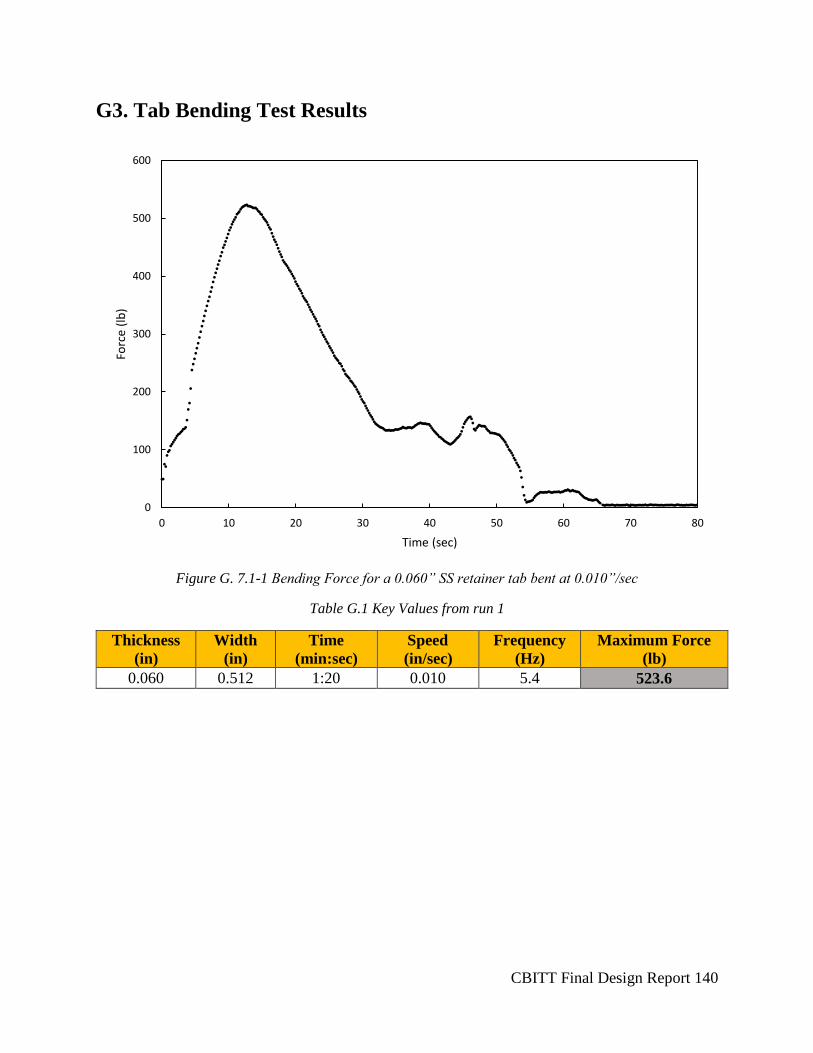
CBITT Final Design Report 140
G3. Tab Bending Test Results
Figure G. 7.1-1 Bending Force for a 0.060” SS retainer tab bent at 0.010”/sec
Table G.1 Key Values from run 1
Thickness
(in)
Width
(in)
Time
(min:sec)
Speed
(in/sec)
Frequency
(Hz)
Maximum Force
(lb)
0.060 0.512 1:20 0.010 5.4 523.6
0
100
200
300
400
500
600
0 10 20 30 40 50 60 70 80
Forc
e (l
b)
Time (sec)
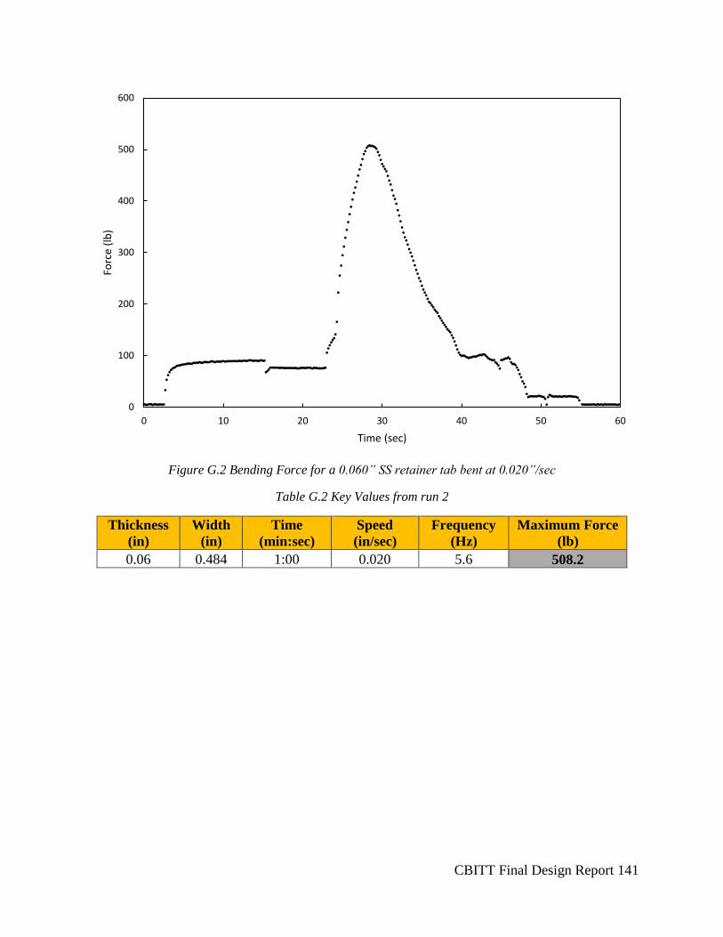
CBITT Final Design Report 141
Figure G.2 Bending Force for a 0.060” SS retainer tab bent at 0.020”/sec
Table G.2 Key Values from run 2
Thickness
(in)
Width
(in)
Time
(min:sec)
Speed
(in/sec)
Frequency
(Hz)
Maximum Force
(lb)
0.06 0.484 1:00 0.020 5.6 508.2
0
100
200
300
400
500
600
0 10 20 30 40 50 60
Forc
e (l
b)
Time (sec)
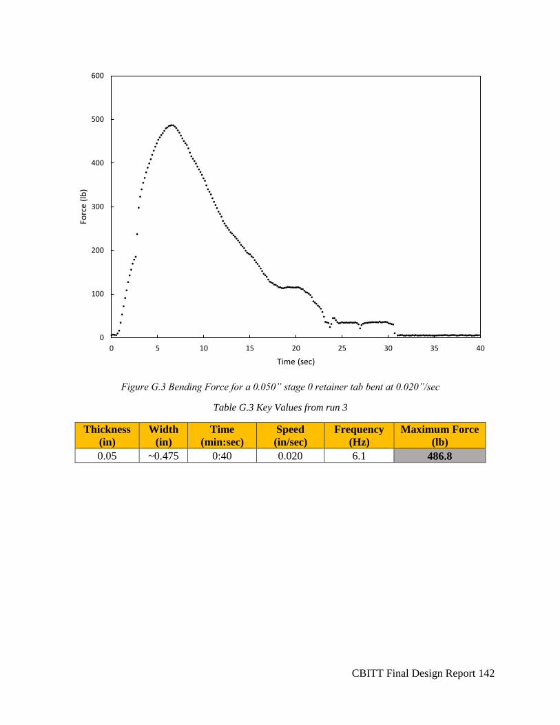
CBITT Final Design Report 142
Figure G.3 Bending Force for a 0.050” stage 0 retainer tab bent at 0.020”/sec
Table G.3 Key Values from run 3
Thickness
(in)
Width
(in)
Time
(min:sec)
Speed
(in/sec)
Frequency
(Hz)
Maximum Force
(lb)
0.05 ~0.475 0:40 0.020 6.1 486.8
0
100
200
300
400
500
600
0 5 10 15 20 25 30 35 40
Forc
e (l
b)
Time (sec)
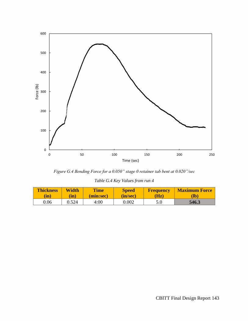
CBITT Final Design Report 143
Figure G.4 Bending Force for a 0.050” stage 0 retainer tab bent at 0.020”/sec
Table G.4 Key Values from run 4
Thickness
(in)
Width
(in)
Time
(min:sec)
Speed
(in/sec)
Frequency
(Hz)
Maximum Force
(lb)
0.06 0.524 4:00 0.002 5.0 546.3
0
100
200
300
400
500
600
0 50 100 150 200 250
Forc
e (l
b)
Time (sec)
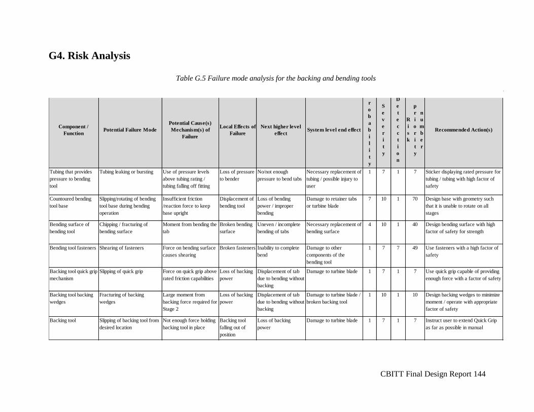
CBITT Final Design Report 144
Component /
FunctionPotential Failure Mode
Potential Cause(s)
Mechanism(s) of
Failure
Local Effects of
Failure
Next higher level
effectSystem level end effect
P
r
o
b
a
b
i
l
i
t
y
S
e
v
e
r
i
t
y
D
e
t
e
c
c
t
i
o
n
R
i
s
k
p
r
i
o
r
i
t
y
n
u
m
b
e
r
Recommended Action(s)
Tubing that provides
pressure to bending
tool
Tubing leaking or bursting Use of pressure levels
above tubing rating /
tubing falling off fitting
Loss of pressure
to bender
No/not enough
pressure to bend tabs
Necessary replacement of
tubing / possible injury to
user
1 7 1 7 Sticker displaying rated pressure for
tubing / tubing with high factor of
safety
Countoured bending
tool base
Slipping/rotating of bending
tool base during bending
operation
Insufficient friction
/reaction force to keep
base upright
Displacement of
bending tool
Loss of bending
power / improper
bending
Damage to retainer tabs
or turbine blade
7 10 1 70 Design base with geometry such
that it is unable to rotate on all
stages
Bending surface of
bending tool
Chipping / fracturing of
bending surface
Moment from bending the
tab
Broken bending
surface
Uneven / incomplete
bending of tabs
Necessary replacement of
bending surface
4 10 1 40 Design bending surface with high
factor of safety for strength
Bending tool fasteners Shearing of fasteners Force on bending surface
causes shearing
Broken fasteners Inability to complete
bend
Damage to other
components of the
bending tool
1 7 7 49 Use fasteners with a high factor of
safety
Backing tool quick grip
mechanism
Slipping of quick grip Force on quick grip above
rated friction capabilities
Loss of backing
power
Displacement of tab
due to bending without
backing
Damage to turbine blade 1 7 1 7 Use quick grip capable of providing
enough force with a factor of safety
Backing tool backing
wedges
Fracturing of backing
wedges
Large moment from
backing force required for
Stage 2
Loss of backing
power
Displacement of tab
due to bending without
backing
Damage to turbine blade /
broken backing tool
1 10 1 10 Design backing wedges to minimize
moment / operate with appropriate
factor of safety
Backing tool Slipping of backing tool from
desired location
Not enough force holding
backing tool in place
Backing tool
falling out of
position
Loss of backing
power
Damage to turbine blade 1 7 1 7 Instruct user to extend Quick Grip
as far as possible in manual
Table G.5 Failure mode analysis for the backing and bending tools
G4. Risk Analysis
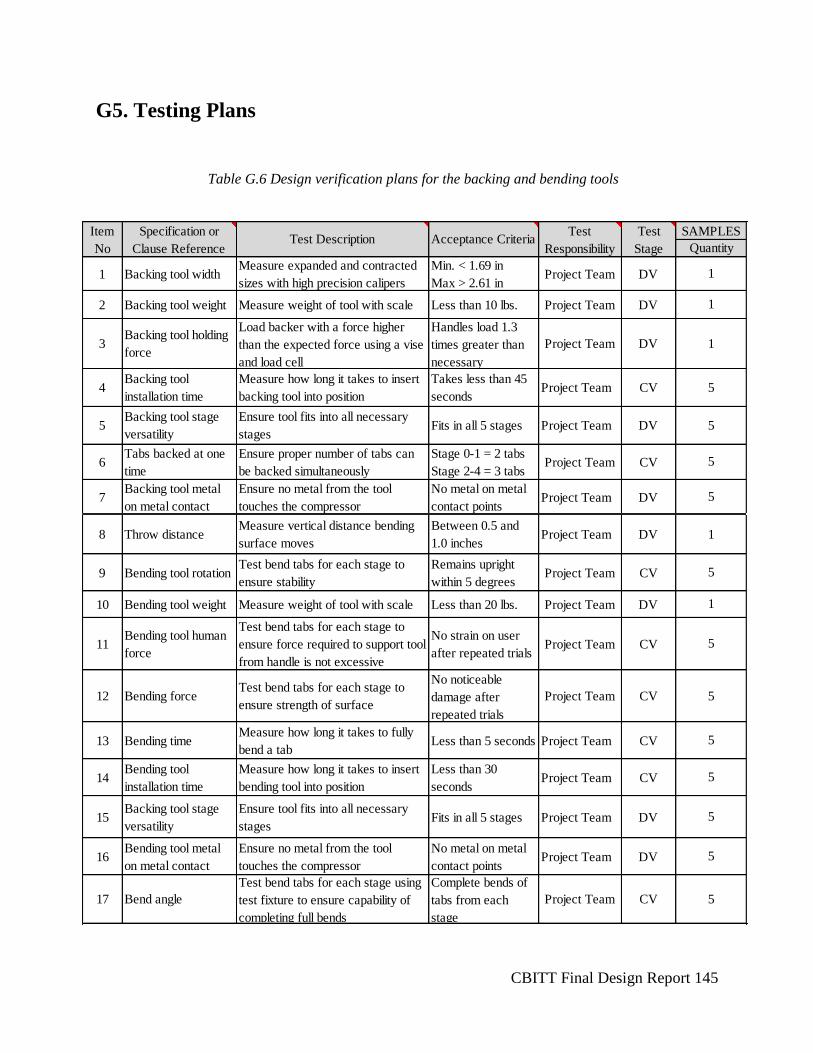
CBITT Final Design Report 145
1 Backing tool widthMeasure expanded and contracted
sizes with high precision calipers
Min. < 1.69 in
Max > 2.61 in Project Team DV
2 Backing tool weight Measure weight of tool with scale Less than 10 lbs. Project Team DV
3Backing tool holding
force
Load backer with a force higher
than the expected force using a vise
and load cell
Handles load 1.3
times greater than
necessary
Project Team DV
4Backing tool
installation time
Measure how long it takes to insert
backing tool into position
Takes less than 45
secondsProject Team CV
5Backing tool stage
versatility
Ensure tool fits into all necessary
stagesFits in all 5 stages Project Team DV
6Tabs backed at one
time
Ensure proper number of tabs can
be backed simultaneously
Stage 0-1 = 2 tabs
Stage 2-4 = 3 tabs Project Team CV
7Backing tool metal
on metal contact
Ensure no metal from the tool
touches the compressor
No metal on metal
contact pointsProject Team DV
8 Throw distanceMeasure vertical distance bending
surface moves
Between 0.5 and
1.0 inchesProject Team DV
9 Bending tool rotation Test bend tabs for each stage to
ensure stability
Remains upright
within 5 degrees Project Team CV
10 Bending tool weight Measure weight of tool with scale Less than 20 lbs. Project Team DV
11Bending tool human
force
Test bend tabs for each stage to
ensure force required to support tool
from handle is not excessive
No strain on user
after repeated trials Project Team CV
12 Bending force Test bend tabs for each stage to
ensure strength of surface
No noticeable
damage after
repeated trials
Project Team CV
13 Bending time Measure how long it takes to fully
bend a tabLess than 5 seconds Project Team CV
14Bending tool
installation time
Measure how long it takes to insert
bending tool into position
Less than 30
secondsProject Team CV
15Backing tool stage
versatility
Ensure tool fits into all necessary
stagesFits in all 5 stages Project Team DV
16Bending tool metal
on metal contact
Ensure no metal from the tool
touches the compressor
No metal on metal
contact pointsProject Team DV
17 Bend angle
Test bend tabs for each stage using
test fixture to ensure capability of
completing full bends
Complete bends of
tabs from each
stage
Project Team CV
Item
No
Specification or
Clause ReferenceTest Description Acceptance Criteria
Quantity
1
1
1
Test
Responsibility
Test
Stage
SAMPLES
5
5
5
5
5
5
5
1
5
5
5
1
5
5
Table G.6 Design verification plans for the backing and bending tools
G5. Testing Plans
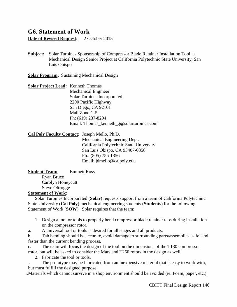
CBITT Final Design Report 146
G6. Statement of Work Date of Revised Request: 2 October 2015
Subject: Solar Turbines Sponsorship of Compressor Blade Retainer Installation Tool, a
Mechanical Design Senior Project at California Polytechnic State University, San
Luis Obispo
Solar Program: Sustaining Mechanical Design
Solar Project Lead: Kenneth Thomas
Mechanical Engineer
Solar Turbines Incorporated
2200 Pacific Highway
San Diego, CA 92101
Mail Zone C-5
Ph: (619) 237-8294
Email: [email protected]
Cal Poly Faculty Contact: Joseph Mello, Ph.D.
Mechanical Engineering Dept.
California Polytechnic State University
San Luis Obispo, CA 93407-0358
Ph.: (805) 756-1356
Email: [email protected]
Student Team: Emmett Ross
Ryan Bruce
Carolyn Honeycutt
Steve Oltrogge
Statement of Work: Solar Turbines Incorporated (Solar) requests support from a team of California Polytechnic
State University (Cal Poly) mechanical engineering students (Students) for the following
Statement of Work (SOW). Solar requires that the team:
1. Design a tool or tools to properly bend compressor blade retainer tabs during installation
on the compressor rotor.
a. A universal tool or tools is desired for all stages and all products.
b. Tab bending should be accurate, avoid damage to surrounding parts/assemblies, safe, and
faster than the current bending process.
c. The team will focus the design of the tool on the dimensions of the T130 compressor
rotor, but will be asked to consider the Mars and T250 rotors in the design as well.
2. Fabricate the tool or tools.
. The prototype may be fabricated from an inexpensive material that is easy to work with,
but must fulfill the designed purpose.
i. Materials which cannot survive in a shop environment should be avoided (ie. Foam, paper, etc.).

CBITT Final Design Report 147
a. Fabrication of some or all components may be performed by Solar, depending on
complexity.
. This should be discussed between the Students and Solar prior to entering the manufacturing
phase.
3. Test the tools.
. Proper fit of all parts into the assembled hardware.
a. Verification of applied forces.
b. Identification of sources of error or variation.
c. Complete gage R&R.
Solar Turbines Deliverables to Student Team: 1. Background information required to solve the proposed problem (ie. dimensions,
materials, procedures, etc.).
2. Engineering assistance & mentorship.
3. Material property data required to complete the project, if necessary.
4. FE analysis support required to complete the project, if necessary.
5. Funding for the project materials.
6. Fabrication support, if necessary.
Cal Poly Student Deliverables to Solar Turbines Incorporated: 1. A report on the preliminary design concept, including drawings and/or sketches.
2. A bill of material & budget required to produce a concept prototype.
3. A physical prototype that meets all of the final design requirements.
4. A final design report, including:
a. Detailed engineering drawings. Geometric Dimensioning and Tolerancing (GD&T) is
recommended, but not required.
b. All prototype CAD model files.
c. All final design calculations and assumptions.
d. Detailed testing plan and results.
General Project Expectations: The student team is expected to treat the project as a business transaction. The student
team is the “vendor” supplying Solar, the customer, with a design to resolve a known
problem. The student team is expected to visit Solar in San Diego twice during the project period.
Once in the Fall Quarter at project kick-off and once in the Spring Quarter at project
completion. Ken Thomas will act as the liaison between Solar and the Students. All the above SOW will be performed by the Cal Poly student team unless required tasks
are outside of the team’s skill set. If questions of capability arise, the liaison will decide
how to resolve the issue. Due to the fast pace and limited time period of the project, milestones (some listed
below) are expected to be met on time. The Cal Poly student team is expected to schedule regular report outs to the advisory
team at Solar to: (a) Update progress toward accomplishing the project milestones.

CBITT Final Design Report 148
(b) Receive feedback from stakeholders at Solar.
(c) Ask/answer questions.
Revisions: This is a “living” document and will be updated where appropriate throughout the project
period to capture changing deliverables, expectations, or milestones.
Period of Project: September 2015 – June 2016
Project Milestones: By the end of First Quarter:
Milestone Expected Completion Date
Student team visits Solar in San Diego October
Complete preliminary design November
Present preliminary design (teleconference) November/December
Submit preliminary design report December (EoQ)
Submit preliminary design bill of material December (EoQ)
By the end of Second Quarter:
Milestone Expected Completion Date
Complete final design No later than January 30th
Finalize bill of material No later than January 15th
Order all required materials February 1st
Complete prototype fabrication March (EoQ)
By the end of Third Quarter:
Milestone Expected Completion Date
Complete prototype initial tests April
Complete prototype final tests on Solar H/W May/June
Student presentation at Solar San Diego May/June
Delivery of prototype to Solar May/June
Delivery of final design report June
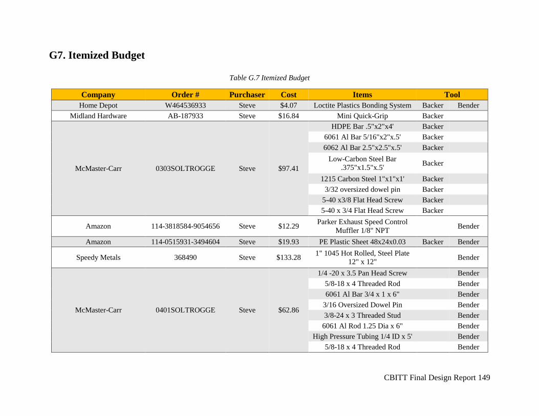
CBITT Final Design Report 149
G7. Itemized Budget
Table G.7 Itemized Budget
Company Order # Purchaser Cost Items Tool
Home Depot W464536933 Steve $4.07 Loctite Plastics Bonding System Backer Bender
Midland Hardware AB-187933 Steve $16.84 Mini Quick-Grip Backer
McMaster-Carr 0303SOLTROGGE Steve $97.41
HDPE Bar .5"x2"x4' Backer
6061 Al Bar 5/16"x2"x.5' Backer
6062 Al Bar 2.5"x2.5"x.5' Backer
Low-Carbon Steel Bar
.375"x1.5"x.5' Backer
1215 Carbon Steel 1"x1"x1' Backer
3/32 oversized dowel pin Backer
5-40 x3/8 Flat Head Screw Backer
5-40 x 3/4 Flat Head Screw Backer
Amazon 114-3818584-9054656 Steve $12.29 Parker Exhaust Speed Control
Muffler 1/8" NPT Bender
Amazon 114-0515931-3494604 Steve $19.93 PE Plastic Sheet 48x24x0.03 Backer Bender
Speedy Metals 368490 Steve $133.28 1" 1045 Hot Rolled, Steel Plate
12" x 12" Bender
McMaster-Carr 0401SOLTROGGE Steve $62.86
1/4 -20 x 3.5 Pan Head Screw Bender
5/8-18 x 4 Threaded Rod Bender
6061 Al Bar 3/4 x 1 x 6" Bender
3/16 Oversized Dowel Pin Bender
3/8-24 x 3 Threaded Stud Bender
6061 Al Rod 1.25 Dia x 6" Bender
High Pressure Tubing 1/4 ID x 5' Bender
5/8-18 x 4 Threaded Rod Bender
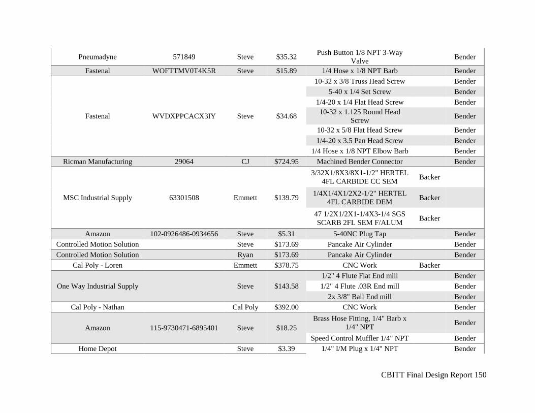
CBITT Final Design Report 150
Pneumadyne 571849 Steve $35.32 Push Button 1/8 NPT 3-Way
Valve Bender
Fastenal WOFTTMV0T4K5R Steve $15.89 1/4 Hose x 1/8 NPT Barb Bender
Fastenal WVDXPPCACX3IY Steve $34.68
10-32 x 3/8 Truss Head Screw Bender
5-40 x 1/4 Set Screw Bender
1/4-20 x 1/4 Flat Head Screw Bender
10-32 x 1.125 Round Head
Screw Bender
10-32 x 5/8 Flat Head Screw Bender
1/4-20 x 3.5 Pan Head Screw Bender
1/4 Hose x 1/8 NPT Elbow Barb Bender
Ricman Manufacturing 29064 CJ $724.95 Machined Bender Connector Bender
MSC Industrial Supply 63301508 Emmett $139.79
3/32X1/8X3/8X1-1/2" HERTEL
4FL CARBIDE CC SEM Backer
1/4X1/4X1/2X2-1/2" HERTEL
4FL CARBIDE DEM Backer
47 1/2X1/2X1-1/4X3-1/4 SGS
SCARB 2FL SEM F/ALUM Backer
Amazon 102-0926486-0934656 Steve $5.31 5-40NC Plug Tap Bender
Controlled Motion Solution Steve $173.69 Pancake Air Cylinder Bender
Controlled Motion Solution Ryan $173.69 Pancake Air Cylinder Bender
Cal Poly - Loren Emmett $378.75 CNC Work Backer
One Way Industrial Supply Steve $143.58
1/2" 4 Flute Flat End mill Bender
1/2" 4 Flute .03R End mill Bender
2x 3/8" Ball End mill Bender
Cal Poly - Nathan Cal Poly $392.00 CNC Work Bender
Amazon 115-9730471-6895401 Steve $18.25
Brass Hose Fitting, 1/4" Barb x
1/4" NPT Bender
Speed Control Muffler 1/4" NPT Bender
Home Depot Steve $3.39 1/4" I/M Plug x 1/4" NPT Bender
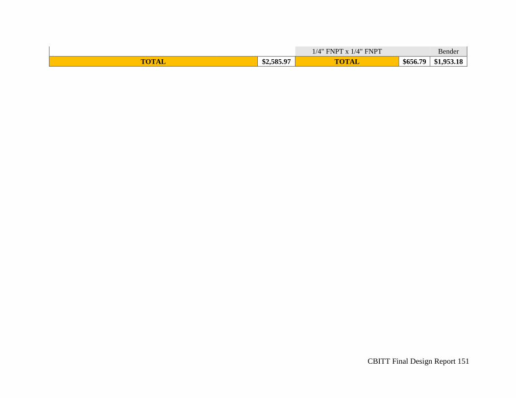
CBITT Final Design Report 151
1/4" FNPT x 1/4" FNPT Bender
TOTAL $2,585.97 TOTAL $656.79 $1,953.18