Embed Size (px)
Citation preview
Solar System Controller
User Manual
MP-3731
2
These operating instructions come with the product and should be kept with it as a reference to all users of the product.
Read these operating instructions carefully before use, Keep them over the entire life of the product, And pass them on to any future owner or user of this product.
This manual describes the installation, function, operation and maintenance of the solar system controller MP-3731.
These operating instructions are intended for end customers. A technical expert must be consulted in cases of uncertainty.
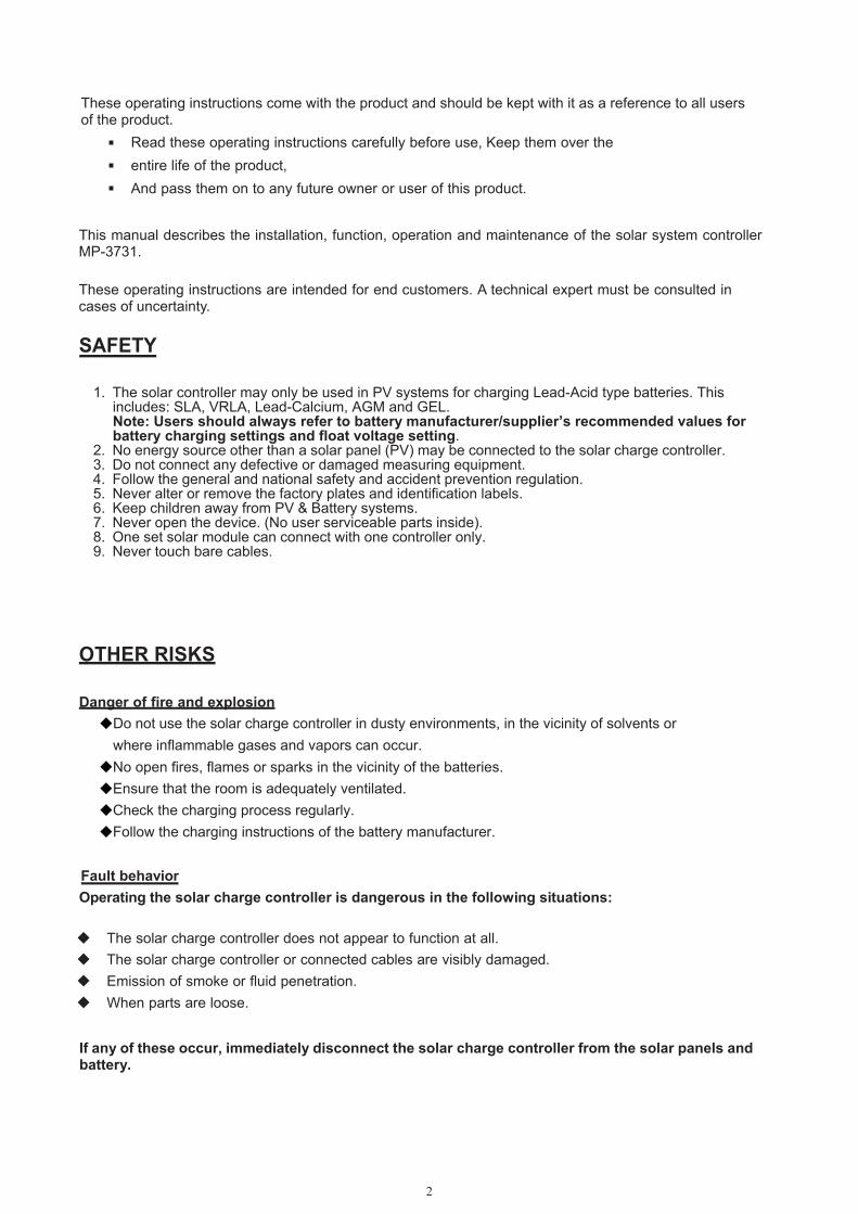
SAFETY
1. The solar controller may only be used in PV systems for charging Lead-Acid type batteries. This includes: SLA, VRLA, Lead-Calcium, AGM and GEL.Note: Users should always refer to battery manufacturer/supplier’s recommended values for battery charging settings and float voltage setting.
2. No energy source other than a solar panel (PV) may be connected to the solar charge controller.3. Do not connect any defective or damaged measuring equipment.4. Follow the general and national safety and accident prevention regulation.5. Never alter or remove the factory plates and identification labels.6. Keep children away from PV & Battery systems.7. Never open the device. (No user serviceable parts inside).8. One set solar module can connect with one controller only.9. Never touch bare cables.
OTHER RISKS
Danger of fire and explosion Do not use the solar charge controller in dusty environments, in the vicinity of solvents or where inflammable gases and vapors can occur. No open fires, flames or sparks in the vicinity of the batteries. Ensure that the room is adequately ventilated. Check the charging process regularly. Follow the charging instructions of the battery manufacturer.
Fault behavior Operating the solar charge controller is dangerous in the following situations:
The solar charge controller does not appear to function at all. The solar charge controller or connected cables are visibly damaged. Emission of smoke or fluid penetration. When parts are loose.
If any of these occur, immediately disconnect the solar charge controller from the solar panels and battery.
POWER
FAULT
50 Amp MPPTCHARGE CONTROLLER
3
FUNCTIONS This solar system controller is designed to
Monitor the state of charge of the battery; Controls the charging process,
Make sure Solar system works at proper condition. Charging Voltage is user programmable.
OPERATING THE CONTROLLER
The display shows a variety of system data by symbols and digits. Both buttons control all settings and display windows.
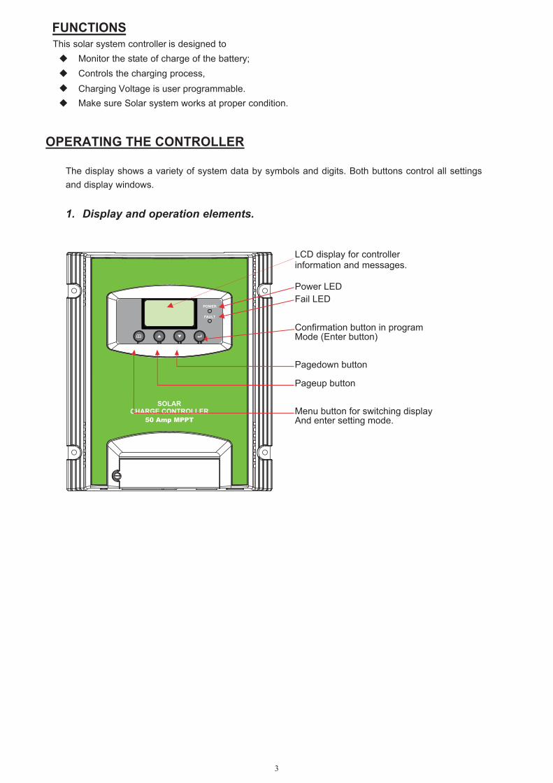
1. Display and operation elements.
LCD display for controller information and messages.
Power LED Fail LED
Confirmation button in program Mode (Enter button)
Pagedown button
Pageup button
Menu button for switching display And enter setting mode.
4
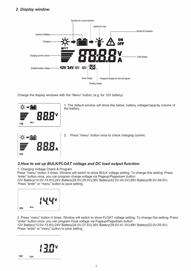
2. Display window.
Change the display windows with the “Menu” button; (e.g. for 12V battery)
1. The default window will show like below, battery voltage/capacity volume ofthe battery.
2. Press “menu” button once to check charging current.
1. Charging Voltage Check & ProgramPress “menu” button 3 times. Window will switch to show BULK voltage setting. To change this setting; Press“enter” button once, you can program charge voltage via Pageup/Pagedown button:12V Battery(14.0V-14.8V);24V Battery(28.0V-29.5V);36V Battery(42.0V-44.3V);48V Battery(56.0V-59.0V) Press “enter” or “menu” button to save setting.
2. Press “menu” button 4 times. Window will switch to show FLOAT voltage setting. To change this setting; Press“enter” button once; you can program Float voltage via Pageup/Pagedown button:12V Battery(13.0V-13.8V);24V Battery(26.0V-27.5V);36V Battery(39.0V-41.3V);48V Battery(52.0V-55.0V) Press “enter” or “menu” button to save setting.
3.How to set up BULK/FLOAT voltage and DC load output function.
5
3. Note:When the "Sensor Temp" port is inserted into the temperature sensor,Float voltage will vary accordinglyto the ambient temperatures stated below:
12V system: ≤0℃(14.1V), 0℃ - 20℃ (13.8V), ≥20℃ (13.5V);24V system: ≤0℃(28.2V), 0℃ - 20℃ (27.6V), ≥20℃ (27.0V);36V system: ≤0℃(42.3V), 0℃ - 20℃ (41.4V), ≥20℃ (40.5V);48V system: ≤0℃(56.4V), 0℃ - 20℃ (55.2V), ≥20℃ (54.0V);
FEATURES
1. Use with 12V/24V/36V/48V battery bank, the controller will detect voltage of battery automatically.With 3 charging stage: MPPT,constant voltage charging, and float charging, they are automatically performed.
2.MPPT function - Implementing the latest MPPT technology the controller is able to harness the panelsmaximum available output at all times.
3. Temperature CompensationISC5040 has an internal ambient temperature sensor that compensates during the float mode.
INSTALLATION
Install the controller in a ventilated area away from flammable materials and gases. The surface should be solid, even, dry and nonflammable. The battery to controller cable should be as short as possible (1-2mtrs is ideal) and be of a suitable diameter
to minimize voltage loss. Do not assemble outdoor, the unit should be installed in the way to be protected against humidity, dripping,
rainwater as well as direct and indirect heat (sunlight). To ensure the air circulation for cooling an area of 15cm on each side of the unit must be kept free. The LCD display should be protected against UV rays (e.g. sunlight). Long time exposure to UV rays can
permanently discolor the LCD. Follow the installation and operating instructions for all components of the PV system. Ensure that no cables are damaged. Ensure that polarity of Solar panel/battery/load is correct and use only insulated tools.
WARNING
4. When the unit is in the default display mode, Pressing the “enter”button will turn the load ON or OFF manually.The arrow/lamp symbol will be displayed when the load terminal is ON.
4. DC Load Output12/24/36/48V Max Output Current 50 A.
MP-3731 can work with input voltage up to 95 Vdc maximum; when installing at this voltage, particularly with regard to module open circuit voltage (Voc), the entire solar energy system must be installed with protection class II. Cover solar modules during installation and use only insulated tools. DC load external power supply or battery is prohibited.
6
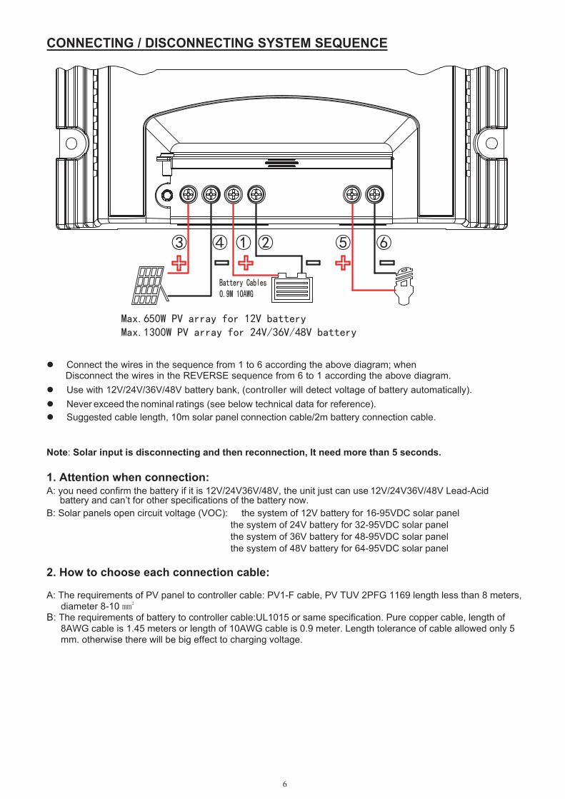
CONNECTING / DISCONNECTING SYSTEM SEQUENCE
Connect the wires in the sequence from 1 to 6 according the above diagram; when Disconnect the wires in the REVERSE sequence from 6 to 1 according the above diagram. Use with 12V/24V/36V/48V battery bank, (controller will detect voltage of battery automatically). Never exceed the nominal ratings (see below technical data for reference). Suggested cable length, 10m solar panel connection cable/2m battery connection cable.
Note: Solar input is disconnecting and then reconnection, It need more than 5 seconds.
1. Attention when connection:A: you need confirm the battery if it is 12V/24V36V/48V, the unit just can use 12V/24V36V/48V Lead-Acid battery and can’t for other specifications of the battery now. B: Solar panels open circuit voltage (VOC): the system of 12V battery for 16-95VDC solar panel
the system of 24V battery for 32-95VDC solar panelthe system of 36V battery for 48-95VDC solar panelthe system of 48V battery for 64-95VDC solar panel
2. How to choose each connection cable:
A: The requirements of PV panel to controller cable: PV1-F cable, PV TUV 2PFG 1169 length less than 8 meters, diameter 8-10 B: The requirements of battery to controller cable:UL1015 or same specification. Pure copper cable, length of
8AWG cable is 1.45 meters or length of 10AWG cable is 0.9 meter. Length tolerance of cable allowed only 5 mm. otherwise there will be big effect to charging voltage.
③ ④ ① ② ⑤ ⑥
Max.650W PV array for 12V battery Max.1300W PV array for 24V/36V/48V battery
7
SPECIFICATIONS
CHARGING CURVE
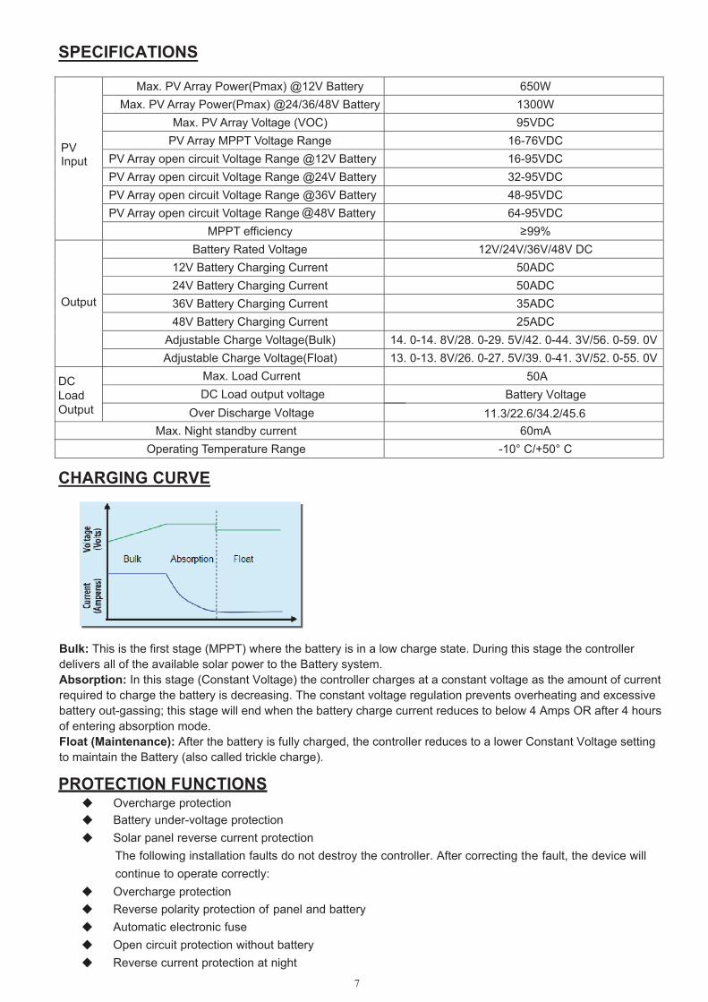
Bulk: This is the first stage (MPPT) where the battery is in a low charge state. During this stage the controller delivers all of the available solar power to the Battery system.Absorption: In this stage (Constant Voltage) the controller charges at a constant voltage as the amount of current required to charge the battery is decreasing. The constant voltage regulation prevents overheating and excessive battery out-gassing; this stage will end when the battery charge current reduces to below 4 Amps OR after 4 hours of entering absorption mode. Float (Maintenance): After the battery is fully charged, the controller reduces to a lower Constant Voltage setting to maintain the Battery (also called trickle charge).
PROTECTION FUNCTIONS Overcharge protection Battery under-voltage protection Solar panel reverse current protection The following installation faults do not destroy the controller. After correcting the fault, the device will continue to operate correctly: Overcharge protection Reverse polarity protection of panel and battery Automatic electronic fuse Open circuit protection without battery Reverse current protection at night
W056 yrettaB V21@ )xamP(rewoP yarrA VP .xaM W0031 yrettaB V84/63/42@ )xamP(rewoP yarrA VP .xaM CDV59 )COV( egatloV yarrA VP .xaMCDV67-61 egnaR egatloV TPPM yarrA VPCDV59-61 yrettaB V21@ egnaR egatloV tiucric nepo yarrA VPCDV59-23 yrettaB V42@ egnaR egatloV tiucric nepo yarrA VPCDV59-84 yrettaB V63@
@ egnaR egatloV tiucric nepo yarrA VP
CDV59-46yrettaB V84 egnaR egatloV tiucric nepo yarrA VP
PVInput
%99≥ ycneiciffe TPPM CD V84/V63/V42/V21 egatloV detaR yrettaB
CDA05 tnerruC gnigrahC yrettaB V21 CDA05 tnerruC gnigrahC yrettaB V42 CDA53 tnerruC gnigrahC yrettaB V63 CDA52 tnerruC gnigrahC yrettaB V84
Adjustable Charge Voltage(Bulk) 14. 0-14. 8V/28. 0-29. 5V/42. 0-44. 3V/56. 0-59. 0V
Output
Adjustable Charge Voltage(Float) 13. 0-13. 8V/26. 0-27. 5V/39. 0-41. 3V/52. 0-55. 0V
Am06 tnerruc ybdnats thgiN .xaMC °05+/C °01- egnaR erutarepmeT gnitarepO
Max. Load CurrentDC Load output voltage Battery Voltage
Over Discharge Voltage 11.3/22.6/34.2/45.6
50ADC Load Output
8
MAINTENANCE The controller is maintenance-free. We strong suggest that all components of the PV system must be checked at least annually,
Ensure adequate ventilation of the cooling element Check the cable strain relief Check that all cable connections are secure Tighten screws if necessary Terminal corrosion
ERROR MESSAGES Caution! Please do not open the controller or attempt to replace components when troubleshooting. Improper maintenance can be hazardous to the user and the system. If the controller detects errors or unauthorized operating states, it shows error codes on the display. Error codes can generally be differentiated, whether there is a temporary malfunction, e.g. regulator overload or a more serious system error that can be remedied by appropriate external measures. Since not all errors can be simultaneously displayed, the error with the highest error number (priority) is displayed. If several errors are present, the second error code is displayed after remedying the more significant error.
The
Remark: When PV connected into the system, while battery disconnected, E1 and E2 may occur. This is normal.
following meaning is assigned to the different error codes:
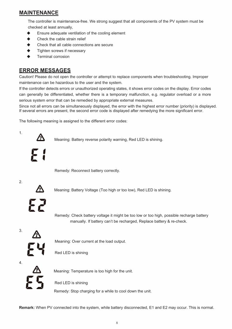
1.
Meaning: Battery reverse polarity warning, Red LED is shining.
Remedy: Reconnect battery correctly.
2.
3.
4.
Meaning: Battery Voltage (Too high or too low), Red LED is shining.
Remedy: Check battery voltage it might be too low or too high, possible recharge battery manually. If battery can’t be recharged, Replace battery & re-check.
Meaning: Temperature is too high for the unit.
Red LED is shining
Remedy: Stop charging for a while to cool down the unit.
Meaning: Over current at the load output.
Red LED is shining
Waste electrical products should not be disposed of with household waste Please recycle where facilities exist Check with your local authority or retailer for recycling advice
DISTRIBUTED BY:TechBrands by Electus Distribution Pty. Ltd.320 Victoria Rd, RydalmereNSW 2116 AustraliaPh: 1300 738 555Int’l: +61 2 8832 3200Fax: 1300 738 500www.techbrands.comMade in China