Embed Size (px)
Citation preview
Solar Simulation for the CREST PreflightThermal-Vacuum Test at B-2
In June 2011, the multi-university sponsored Cosmic Ray Electron Synchrotron Telescope (CREST) has undergone thermal-vacuum qualification testing at the NASA Glenn Research Center (GRC), Plum Brook Station, Sandusky, Ohio. The testing was performed in the B-2 Space Propulsion Facility vacuum chamber. The CREST was later flown over the Antarctic region as the payload of a stratospheric balloon. Solar simulation was provided by a system of planar infrared lamp arrays specifically designed for CREST. The lamp arrays, in conjunction with a liquid-nitrogen-cooled cold wall, achieved the required thermal conditions for the qualification tests.
The following slides accompanied the presentation of the report entitled “Solar Simulation for the CREST Preflight Thermal-Vacuum Test at B-2”, at the 27th
Aerospace Testing Seminar, October 2012. The presentation described the test article, the test facility capability, the solar simulation requirements, the high-lights of the engineering approach, and the results achieved. The presentation was intended to generate interest in the report and in the B-2 test facility.
1
https://ntrs.nasa.gov/search.jsp?R=20130010977 2019-04-04T16:17:16+00:00Z
National Aeronautics and Space Administration
www.nasa.gov 2
“Solar Simulation for the CREST Preflight Thermal-Vacuum Test at B-2”
Author: Robert A. Ziemke
Presented by: Rachel E. Maynard
NASA Glenn Research Center Plum Brook Station, Sandusky, Ohio
Aerospace Testing Seminar, Los Angeles, CAOctober 16-18, 2012
National Aeronautics and Space Administration
www.nasa.gov
OUTLINE
• Introduction• Solar Simulation Requirements• Engineering Approach• Optimizing Flux Uniformity• Setting the Infrared Flux Density Levels• Final Solar Simulation Layout• Conclusion
3
National Aeronautics and Space Administration
www.nasa.gov
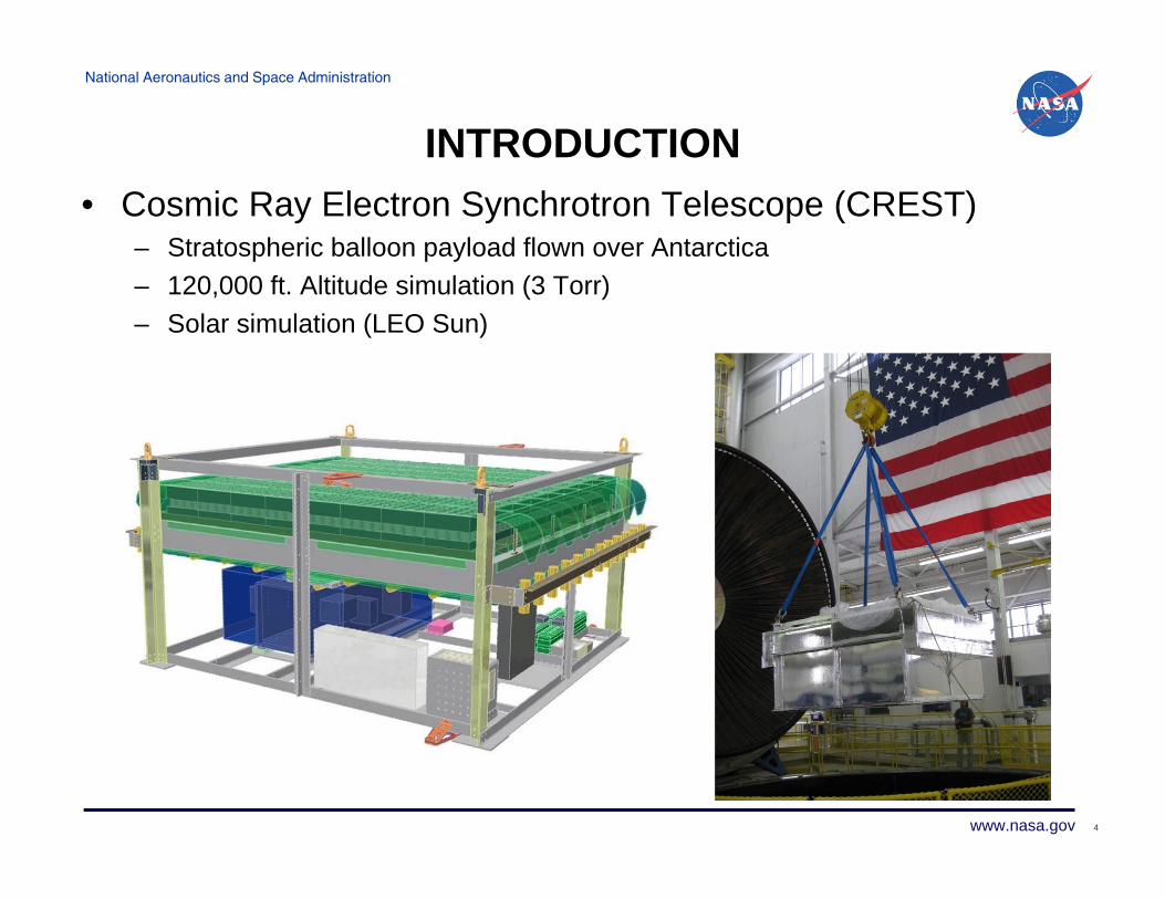
INTRODUCTION• Cosmic Ray Electron Synchrotron Telescope (CREST)
– Stratospheric balloon payload flown over Antarctica– 120,000 ft. Altitude simulation (3 Torr)– Solar simulation (LEO Sun)
4
National Aeronautics and Space Administration
www.nasa.gov
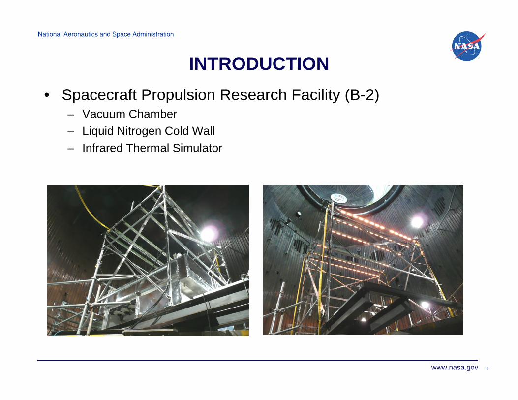
INTRODUCTION• Spacecraft Propulsion Research Facility (B-2)
– Vacuum Chamber– Liquid Nitrogen Cold Wall– Infrared Thermal Simulator
5
National Aeronautics and Space Administration
www.nasa.gov
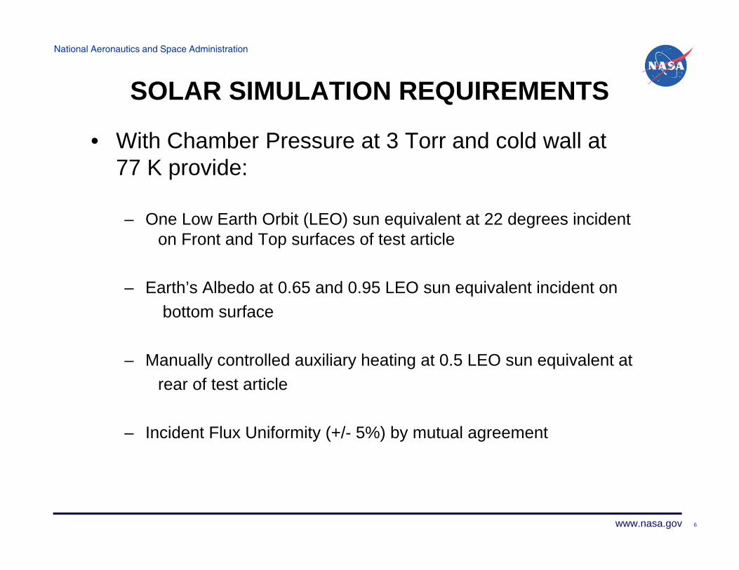
SOLAR SIMULATION REQUIREMENTS
• With Chamber Pressure at 3 Torr and cold wall at 77 K provide:
– One Low Earth Orbit (LEO) sun equivalent at 22 degrees incident on Front and Top surfaces of test article
– Earth’s Albedo at 0.65 and 0.95 LEO sun equivalent incident onbottom surface
– Manually controlled auxiliary heating at 0.5 LEO sun equivalent atrear of test article
– Incident Flux Uniformity (+/- 5%) by mutual agreement
6
National Aeronautics and Space Administration
www.nasa.gov
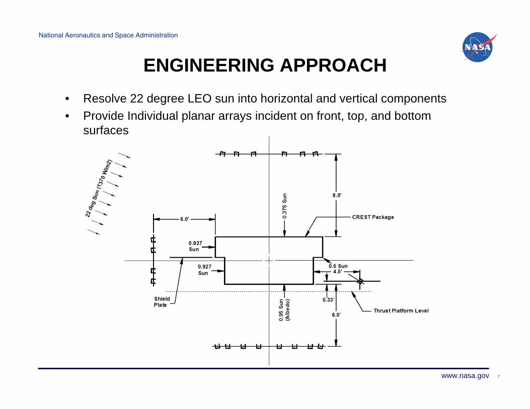
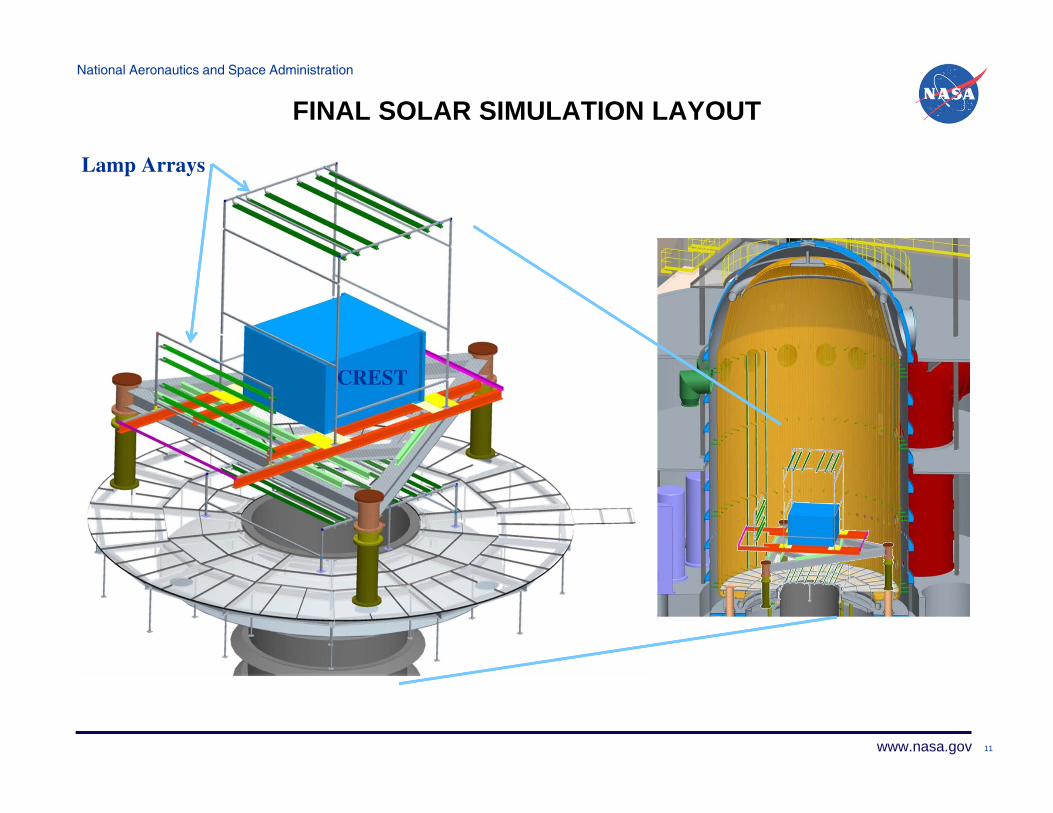
ENGINEERING APPROACH• Resolve 22 degree LEO sun into horizontal and vertical components• Provide Individual planar arrays incident on front, top, and bottom
surfaces
7

National Aeronautics and Space Administration
www.nasa.gov
ENGINEERING APPROACH• Assemble planar arrays from 12 ft. IR line sources borrowed from
existing B-2 thermal simulator• Accept inherent longitudinal flux fall-off of line sources• Optimize transverse flux uniformity based on theoretical prediction
8
‐25.0
‐20.0
‐15.0
‐10.0
‐5.0
0.0
5.0
10.0
15.0
20.0
25.0
‐6 ‐5 ‐4 ‐3 ‐2 ‐1 0 1 2 3 4 5 6
Relativ
e Flux
Den
sity (percent)
Distance from Center (feet)
CRESTPackageW=8.7 ft.
Longitudinal Flux Distribution
0
200
400
600
800
1000
1200
1400
1600
‐5 ‐4 ‐3 ‐2 ‐1 0 1 2 3 4 5Incide
nt Flux Den
sity (W
/m2)
Distance from Center (feet)
Transverse Flux Distribution
National Aeronautics and Space Administration
www.nasa.gov
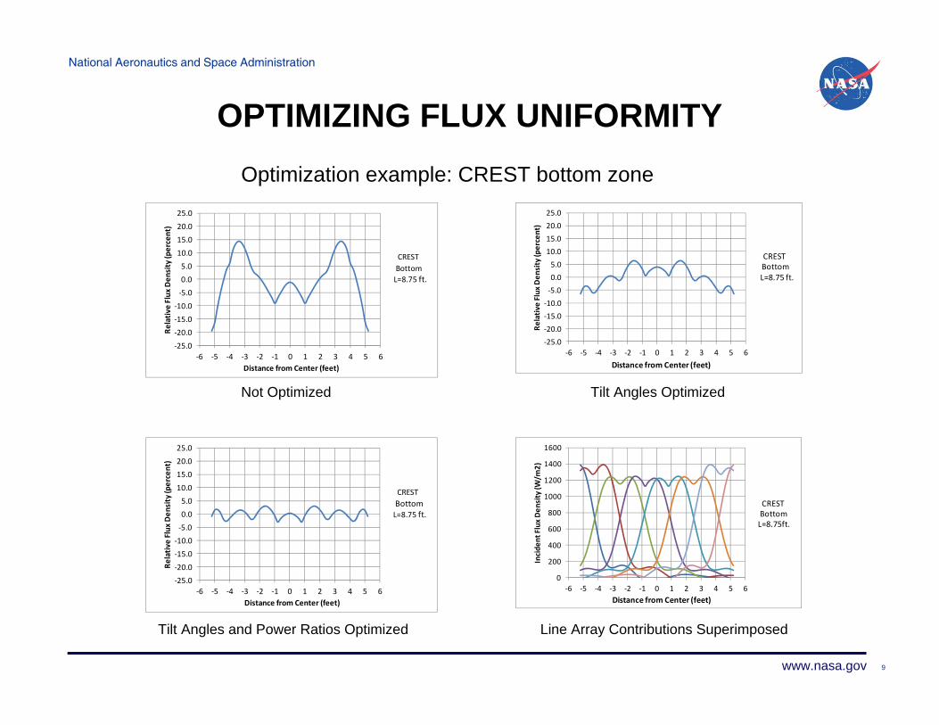
OPTIMIZING FLUX UNIFORMITYOptimization example: CREST bottom zone
Not Optimized Tilt Angles Optimized
Tilt Angles and Power Ratios Optimized Line Array Contributions Superimposed
9
‐25.0
‐20.0‐15.0‐10.0
‐5.00.05.0
10.015.020.0
25.0
‐6 ‐5 ‐4 ‐3 ‐2 ‐1 0 1 2 3 4 5 6
Relativ
e Flux
Den
sity (percent)
Distance from Center (feet)
CRESTBottomL=8.75 ft.
‐25.0‐20.0
‐15.0‐10.0‐5.00.05.0
10.0
15.020.025.0
‐6 ‐5 ‐4 ‐3 ‐2 ‐1 0 1 2 3 4 5 6
Relativ
e Flux
Den
sity (percent)
Distance from Center (feet)
CRESTBottomL=8.75 ft.
‐25.0‐20.0‐15.0‐10.0‐5.00.05.0
10.015.020.025.0
‐6 ‐5 ‐4 ‐3 ‐2 ‐1 0 1 2 3 4 5 6
Relativ
e Flux
Den
sity (percent)
Distance from Center (feet)
CRESTBottomL=8.75 ft.
0
200
400
600
800
1000
1200
1400
1600
‐6 ‐5 ‐4 ‐3 ‐2 ‐1 0 1 2 3 4 5 6
Incide
nt Flux Den
sity (W
/m2)
Distance from Center (feet)
CRESTBottomL=8.75ft.
National Aeronautics and Space Administration
www.nasa.gov
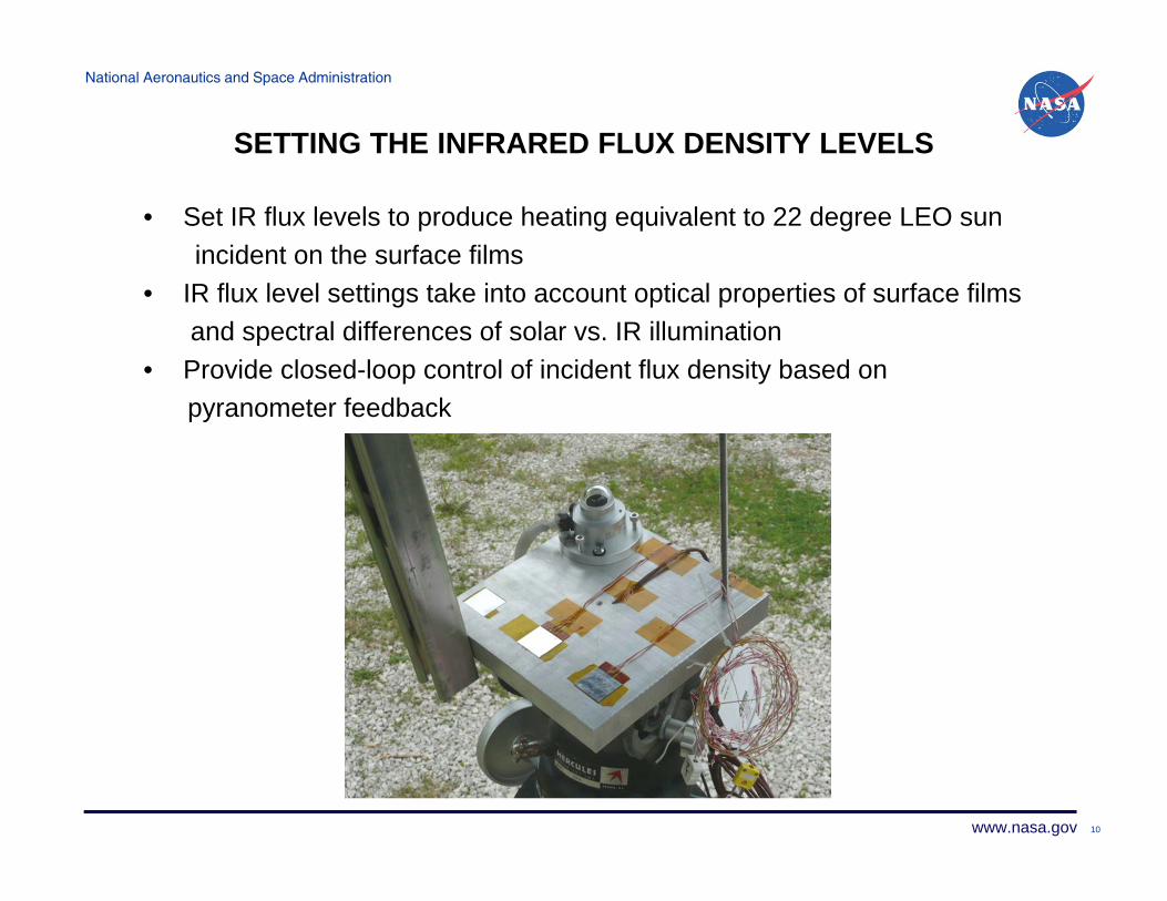
SETTING THE INFRARED FLUX DENSITY LEVELS
• Set IR flux levels to produce heating equivalent to 22 degree LEO sunincident on the surface films
• IR flux level settings take into account optical properties of surface filmsand spectral differences of solar vs. IR illumination
• Provide closed-loop control of incident flux density based onpyranometer feedback
10
National Aeronautics and Space Administration
www.nasa.gov 11
CREST
Lamp Arrays
FINAL SOLAR SIMULATION LAYOUT
National Aeronautics and Space Administration
www.nasa.gov
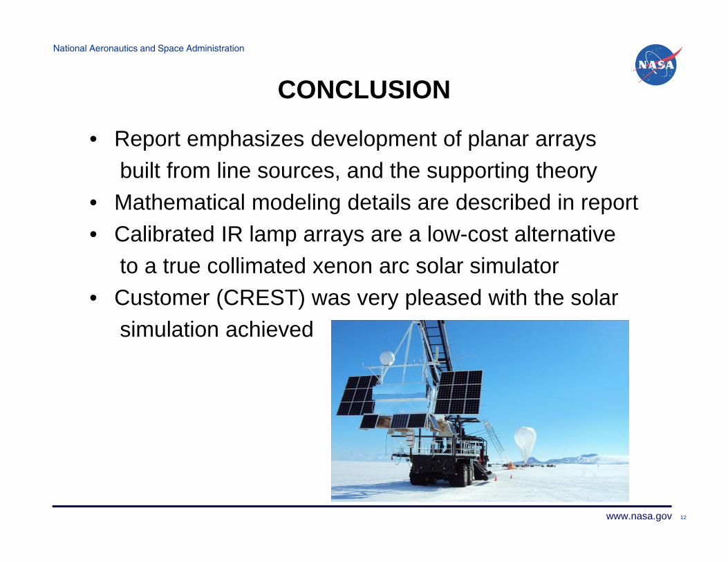
CONCLUSION
• Report emphasizes development of planar arraysbuilt from line sources, and the supporting theory
• Mathematical modeling details are described in report• Calibrated IR lamp arrays are a low-cost alternative
to a true collimated xenon arc solar simulator• Customer (CREST) was very pleased with the solar
simulation achieved
12