Embed Size (px)
Citation preview

Solar Pumping Inverter User Manual
Figure 1 ADA solar pumping inverter
Designed & Manufactured by
Shenzhen ADA Power Electronics Co., Ltd

API series Solar Pumping Inverter
Safety Instruction To ensure safe operation of solar pumping inverter, it mustchoose the right way of transportation,
installation,operation and maintenance. Please be aware of the safety notices before operation:
Warning: Misuse will result in fire, serious injury to person or even death.
Caution: misuse will cause low or middle-grade injury to person or equipment damage.
Prompt: Point out some useful information
First Inspection
Caution
If inverter is damaged or missing parts, no installation allowed in case of any accidents.
Installation
Caution
1.It must be installed vertically for good convection cooling effect .
2.Keep under the condition of good ventilation opening or ventilating device. Never exposes directly to
the sunlight.
Connection
Caution
1.All wirecable connection must be under the instruction of correct wiring diagram .
2.Handling by qualified electrical professionals, all wirecable shoud be wrapped with electrical tape for
safety.
Storage
Caution
Placedindry,dust‐free, no corrosivegas,liquid.
Temperatureofthestoragelocationmustbeatthe‐20℃ to+70℃.
RelativeHumidityofthestoragelocationmustbebetween5%to90%range,andno
condensation.
2 / 17

API series Solar Pumping Inverter
Chapter 1 System Introduction 1.1 Brief Introduction A complete solar pumping system consist of solar array, pump and solar pumping inverter. API series
solar pumping inverter can convert the DC power from solar PV array to AC power to run pump motors.
Solar array, an aggregation of many solar modules connected in series and parallel, absorbs sunlight
radiation and converts it into electrical energy, providing dynamical water for the whole system.
Inverter controls the system operation and adjust the output frequency in real-time according to the
variation of sunlight intensity to realize the maximum power point tracking (MPPT).
Pump, drive by 3-phase AC motor, can draw water from the deep wells or rivers and lakes to pour into the
storage tank or reservoir, or directly connect to the irrigation system, fountain system, etc.
Figure 2 Structure of solar pumping system
3 / 17

API series Solar Pumping Inverter
Chapter 2 Solar Pumping Inverter 2.1 Inverter Specification Model Description A P I 5500 H
H….. HighVoltage L….. .Low Voltage S…..Single Phase ……..5.5KW
……..Inverter
……...Pump
……..AC Remark: “L” means low voltage,3 phase 220V; “H” means high voltage,3 phase 380V. “S”means single phase,220V 2.2 Inverter Features
· Apply to all kinds of single phase or 3 phase AC induction motor .
· With Infineon IGBT .Maximumpowerpoint tracking(MPPT)algorithmfordynamic VI, fast response speed,
goodstability,the efficiency of 99%;
· Both AC and DC input ,and switch automatically .
. For single phase inverter , mppt working voltage is 180V~450V ; for three phase inverter , mppt working voltage is 250V~800V ,
· Remote control , support RS323/RS485 protocol.
. water level monitoring by switching/analogue.
· PV Junction Box with 2 input
· Outdoor water proofIP65 , working environmenttemperature:‐10℃~+40℃
· Lighting protection device.
· Start in the morning and stop in the late afternoon full automatically.
· Full protections : overload , overcurrent, over voltage , undervoltage ,short circuit , dry pumping etc.
· Support GRPSControl (Optional)
. Support Wifi/GSM/3G control (Optional)
4 / 17

API series Solar Pumping Inverter 2.3Parameters :
Solar PumpInverter Solar Array
AC Pump
Model RatedPower
(KW)
Max. DC InputVoltage
(V)
MPPT Voltage(V)
Ratedoutput Voltage(V)
Output Frequency(Hz)
DC Power(KW)
Rated Power(KW)
API750S 0.75 800 250-400 Single PH 220 0-50/60 0.825 0.75
API1500S 1.5 800 250-400 Single PH 220 0-50/60 2.25 1.5
API2200S 2.2 800 250-400 Single PH 220 0-50/60 3.3 2.2
API750L 0.75 800 250-400 3PH220 0-50/60 0.825 0.75
API1500L 1.5 800 250-400 3PH220 0-50/60 2.25 1.5
API2200L 2.2 800 250-400 3PH220 0-50/60 3.3 2.2
API750H 0.75 800 450-800 3PH380 0-50/60 0.825 0.75
API1500H 1.5 800 450-800 3PH380 0-50/60 2.25 1.5
API2200H 2.2 800 450-800 3PH380 0-50/60 3.3 2.2
API4000H 4.0 800 450-800 3PH380 0-50/60 6 4.0
API5500H 5.5 800 450-800 3PH380 0-50/60 8.25 5.5
API7500H 7.5 800 450-800 3PH380 0-50/60 11.25 7.5
API11000H 11 800 450-800 3PH380 0-50/60 16.5 11
API15000H 15 800 450-800 3PH380 0-50/60 20 15
API18000H 18 800 450-800 3PH380 0-50/60 24 18.5
API22000H 22 800 450-800 3PH380 0-50/60 29 22
API30000H 30 800 450-800 3PH380 0-50/60 39 30
API37000H 37 800 450-800 3PH380 0-50/60 48 37
API45000H 45 800 450-800 3PH380 0-50/60 54 45
API55000H 55 800 450-800 3PH380 0-50/60 66 55
API75000H 75 800 450-800 3PH380 0-50/60 90 75
5 / 17

API series Solar Pumping Inverter
2.4 Technical Parameter Table
2.4.1 Single phase inverter (API750S ,API1500S,API2200S)
Input specification
PV Input
Maximum Input DC Voltage 450VDC
Recommended MPPT Voltage Range
250~350VDC
Recommended Input Operation Voltage
310VDC (Vmpp)
Grid or backup generator input
Input voltage Single phase 220V(-15%~30%)
Output specification
Rated output voltage 1PH &3PH 220V
Output frequency 0~600.00Hz(default: 0~50.00Hz)
Protection
Built-in Protection Lighting Protection, over-current, overvoltage, output phase-lose, under-load, under-voltage, short circuit, overheating, water pump
run dry etc. 2.4.2 Three Phase inverter (API750L~API75000H)
Input specification
PV Input
Maximum Input DC Voltage 800VDC
Recommended MPPT Voltage Range
450~600VDC
Recommended Input Operation Voltage
540VDC (Vmpp)
Grid or backup generator input
Input Voltage Three phase 380V(-15%~30%)
Output specification
Rated output voltage 3PH 380V
Output frequency 0~600.00Hz(Default 0~50.00Hz)
Protection
Built-in Protection Lighting Protection, over-current, overvoltage, output phase-lose, under-load, under-voltage, short circuit,
overheating, water pump run dry etc.
General Parameters
Application Site No direct sunshine, no dust, corrosive gas, combustible gas,
oil mist, steam, dripping or salinity etc.
Altitude 0~2000 m
Derated use above 1000m,per 100m, the rated output
6 / 17

API series Solar Pumping Inverter current decrease 1%.
Environment Temperature -10℃~40℃ (Environment Temperature be 40℃~50℃,
please keep derated use.)
Humidity 5~95%,non-condensation
Vibration less than 5.9 m/s2(0.6g)
Storage Temperature -20℃~+70℃
Efficiency Rated Power Run≥93%
Installation Wall or rail mounting
Protection Grade IP65
Cooling Forced Air Cooling
2.5 Inverter Introduction 2.5.1 Brief Instruction
Figure 3 Inverter front panel
Figure 4 Inverter terminal board
AC Output
PV DC Input
Keypad
ON/OFF
Sensor
AC Input
Air Valve
GPRS/3G/WIF
AC/DC Switch
7 / 17

API series Solar Pumping Inverter
Figure 5 Inverter keypad
2.5.2 Operation panel button and potentiometer function
MENE/ESC Enter or exit Level I menu
ENTER/DATA
Enter the menu interfaces level by level, and confirm the
parameter setting
UP Increase data or function code
DOWN Decrease date or function code
SHIFT
Select the displayed parameters in turn in the stop or running
state, and select the digit to be modified when modifying
parameters
RUN Start the inverter in the keypad control mode
STOP/RESET
Stop the inverter when it is in the running state and perform the
reset operation when it is in the fault state
JOG/REV
Perform function switchover (such as jog run and quick
switchover of command source or direction)
8 / 17

API series Solar Pumping Inverter 2.5.3 Outer plug instruction:
Socket Terminal Wire description Connection Description
PV Input Positive Red wire single strand
connected positive pole of
PV array
PV Input Negative Black wire single strand
connected negative pole of
PV array
AC Input 3 Core Wire
Red Wire L1 Phase
Green Wire L2 Phase
Yellow Wire L3 Phase
AC Output 4 Core Wire
Black U Phase
Black V Phase
Black W Phase
Yellow-green Ground
Sensor 5 Core Wire
Yellow Wire The high level of tank sensor
Orange Wire The low level of tank sensor
Red Wire The high level of reservoir sensor
Black The low level of reservoir
Brown Wire —
9 / 17
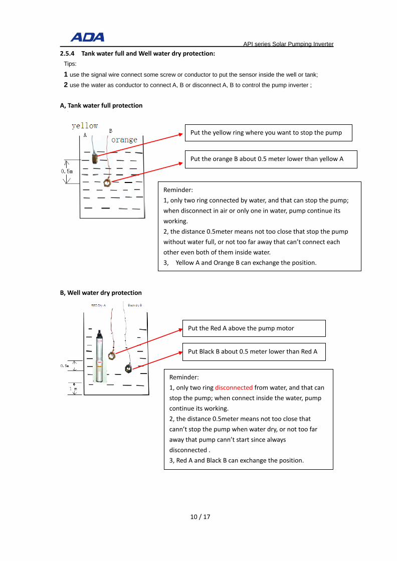
API series Solar Pumping Inverter 2.5.4 Tank water full and Well water dry protection:
Tips:
1 use the signal wire connect some screw or conductor to put the sensor inside the well or tank;
2 use the water as conductor to connect A, B or disconnect A, B to control the pump inverter ;
A, Tank water full protection
B, Well water dry protection
Put the yellow ring where you want to stop the pump
Put the orange B about 0.5 meter lower than yellow A
Reminder: 1, only two ring connected by water, and that can stop the pump; when disconnect in air or only one in water, pump continue its working. 2, the distance 0.5meter means not too close that stop the pump without water full, or not too far away that can’t connect each other even both of them inside water. 3, Yellow A and Orange B can exchange the position.
Put the Red A above the pump motor
Put Black B about 0.5 meter lower than Red A
Reminder: 1, only two ring disconnected from water, and that can stop the pump; when connect inside the water, pump continue its working. 2, the distance 0.5meter means not too close that cann’t stop the pump when water dry, or not too far away that pump cann’t start since always disconnected . 3, Red A and Black B can exchange the position.
10 / 17

API series Solar Pumping Inverter
Chapter 3 Function Parameters 3.1 The Basic Function Parameters The symbols in the function code table are described as follows:
"○" means the value of this parameter can be modified in stop and running status of drive;
"◎" means the value of this parameter cannot be modified when drive is running;
"●" means this parameter is a measured value that cannot be modified;
Default: The value when restored to factory default. Neither measured parameter value nor recorded
value will be restored.
Setting Range: the scope of setting and display of parameters.
Code Name Description Factory
Default
Attrib
ute
P00.01 Command Source
Selection of Run/Start
0:Operation Panel(LED off)
1:Terminal Panel(L/R on)
2:Computer Communications(L/R flash)
1 ○
P00.14 Acceleration Time 0 0.0s~3600.0s 2.0s ○
P00.15 Deceleration Time 0 0.0s~3600.0s 0.1s ○
P01.05 Stop mode 0:Ramp to stop
1:Coast to stop 1 ○
P01.22 Terminal Control
When Power-On
0:Terminal Command Enabled
1:Terminal Command Disabled 1 ○
P01.23 Restart when Power-off 0:Forbid to Restart
1:Allow to restart 1 ○
P01.24 Wait Time of Restart
When Power-off 0.0~3600.0s(whenP01.23, 1Mean Enabled) 1.0s ○
P02.00 Motor1 type 0:Asynchronous motor 0 ●
P02.01 Motor 1 Rated Power 0.4kW~1000.0kW Model Set ◎
P02.02 Motor 1 Rated Voltage 0V~1500V Model Set ◎
P02.03 Motor 1 Rated Current 0.0A~2000.0A Model Set ◎
P02.04 Motor 1 Rated Frequency 0.00Hz~650.00Hz Model Set ◎
P02.05 Motor 1 Rated Rotational 0RPM~65535RPM Model Set ◎
11 / 17

API series Solar Pumping Inverter Speed
P05.01 Terminal DI1 Function
Selection
0: Disabled
1: Forward run
49:PV Inverter Forbid
50:Full-Water
51:Dry -Water
1 ◎
P05.02 Terminal DI2 Function
Selection 50 ◎
P05.03 Terminal DI3 Function
Selection 51 ◎
P05.04 Terminal DI4 Function
Selection 49 ◎
P05.05 Terminal DI5 Function
Selection 0 ◎
P05.11 Terminal DI1~DI5
Positive/Negative Logic 0x00~0x1FF 4 ◎
P05.12 DI Terminal Filtering Time 0.000~1.000s 0.010s ○
P06.02 Output Terminal
Positive/Negative Logic 0x0~0x1F 0x0 ○
P06.03 DO1 Output Function 0:Disabled
16:Weak Light Pre-Warning
17:Full-Water Pre-Warning
18:Reservoir Dry-Water
19:Analog Reservoir Dry Pumping
20:Terminal Reservoir Dry-Water
16 ○
P06.04 HDO1 Output Function 0 ○
P06.05 Relay T1 Output Function 17 ○
P06.06 RelayT2 Output Function 20 ○
P08.26 PID Dormancy Wait Time 0.0s~6000.0s 1.0s ○
P11.16 PV Inverter Selection 0:Disabled
1:Enabled 1 ○
P11.17 Vmpp Voltage Selection 0:Constant Voltage
1:Max. Power Point Tacking(MPPT) 1 ○
P11.18 Vmpp Voltage Keypad
Set 0.0~6553.5Vdc 555.0V ○
P11.19 PID OffsetLimits 0.0~100.0%(100.0%对应P11.18) 0.0% ◎
P11.20 PID Max. Output
Frequency 0~100.0% 100.0% ○
P11.21 PID Min. Output
Frequency 0.0%~100.0% 0.0% ○
P11.22 KP1 0.00~100.00 1.00 ○
P11.23 KI1 0.00~100.00 1.00 ○
P11.24 KP2 0.00~100.00 4.00 ○
P11.25 KI2 0.00~100.00 4.00 ○
12 / 17

API series Solar Pumping Inverter
P11.26 PI Amplitude 0.0~6553.5Vdc 50.0V ○
P11.27
Analog Channel
Selection of Reservoir
Water Level
0:Disabled
1:AI1
2:AI2
3:AI3
0 ○
P11.28 Dry-Water Threshold 0.0~100.0% 25.0% ○
P11.29 Delay Time of Dry-Water 0~10000s 10s ○
P11.30 Wake-up Delay Time of
Dry-Water 0~10000s 300s ○
P11.31 Dry Pumping Threshold 0.0~50.0% 0.0% ○
P11.32 Delay Time of Full-Water 0.0~1000.0s 60.0s ○
P11.33 Dry Pumping Function 0: Disabled
1: Enabled 0 ○
P11.34 Reset Delay of Full-Water 0.0~1000.0s 300.0s ○
P11.35 Frequency of Weak Light 0~50Hz 5.00Hz ○
P11.36 Delay Time of Weak Light 0.0~3600.0s 100.0s ○
P11.37 Reset Delay of Weak
Light 0.0~3600.0s 300.0s ○
P11.38 Reference Voltage of
Given Display 0.0~2000.0V 0V ○
P11.39 Min. Voltage of MPPT 0.0~6553.5Vdc 100.0V ○
P11.40 Max. Voltage of MPPT 0.0~6553.5Vdc 800.0V ○
P14.01 Fault Code
0:No Fault A-LS Warning of Weak Light A-LL Warning of Dry-water A-TF Warning of Full -water Er001:Acceleration Overcurrent(Hardware) Er002:Deceleration Overcurrent(Hardware) Er003:Constant-speed Overcurrent(Hardware) Er004:Acceleration Overcurrent Er005:Deceleration Overcurrent Er006:Constant-speed Overcurrent Er007:Acceleration Overvoltage Er008:Deceleration Overvoltage Er009:Constant-speed Overvoltage Er010:Bus Under voltage protection Er011:Motor Overload Er012:Inverter Overload Er013:Input Open-phase Er014:Output Open-phase Er015:Overheat Er016:Over Current Fault
0 ●
13 / 17

API series Solar Pumping Inverter Er017:External Input Fault Er018:Communication Fault Er019:Current Inspect Fault Er020:Self-identification Fault Er021:EEPROM Version Incompatible Er022:PID Feedback Over Limit Er023:PIDfeedback Disconnection on Running Er024:Motor Ground Circuit Fault Er025:-- Er026:-- Er027:Run Time Over Er028:Power-on Time Over Er029:Off Load Er030:-- Er031:-- Er032:-- Er033:-- Er034:Motor Over Heat Er035:-- Er036:Electronic Over Load Er037~Er040:-- Er041:User Defined Fault 1 Er042:User Defined Fault 2 Er043:User Defined Fault 3 Er044:User Defined Fault 4 Er060:User Time Lock Er061:Factory Time Lock
P14.02 Output Frequency When
Fault 0.00~650.00Hz 0.00 ●
P14.03 Output Current When
Fault 0.0~2000.0A 0.0 ●
P14.04 Output Voltage When
Fault 0~2000V 0 ●
P14.05 Busbar Voltage when
Fault 0.0~2000.0V 0.0 ●
P14.06 Input Terminal Status
When Fault 0x00~0x1FF 0x00 ●
P14.07 Output Terminal Status
When Fault 0x00~0x1F 0x00 ●
P14.08 Inverter Temperature
When Fault -20.0~120.0°C 0.0 ●
P14.09 Run Time When Fault 0~65535min 0 ●
P14.10 Power-On Time when
Fault 0~65535min 0 ●
P14.11 Total Run Time when
Fault 0~65535h 0 ●
P14.12 Total Power-on When
Fault 0~65535h 0 ●
14 / 17

API series Solar Pumping Inverter
P28.00 Run Frequency 0.00Hz~300.00 0.00 ●
P28.01 Set Frequency 0.00Hz~300.00 0.00 ●
P28.02 Slope Set Frequency 0.00Hz~300.00 0.00 ●
P28.03 Busbar Voltage 0.0~2000.0V 0.0 ●
P28.04 Output Voltage 0~1200V 0 ●
P28.05 Output Current 0.0~2000.0A 0.0 ●
P29.00 User Password 0~65535 0 ○
P29.01 Parameter Initialization
0:No Operation
1:Factory Reset
2:Remove Factory Record
3:Remove Total Run/Power-On Time
0 ◎
P29.02 Item Code 0~65535 Factory Set ●
P29.03 Software Version 1.00~10.00 Factory Set ●
P29.04 Inverter Rated Power 0.4~1000.0kW Factory Set ●
P29.05 Inverter Rated Voltage 220~1140V Factory Set ●
P29.06 Inverter Rated Current 2.4~2000.0A Factory Set ●
15 / 17

API series Solar Pumping Inverter
Chapter 4 Warranty 4.1 Warranty
The warranty of this inverter is 18 months , or we provide 2% spare parts for free. When any fault
or damage occurs on the product, within the warranty period, our company will provide free
maintenance. After the warranty time, we can provide lifetime paid warranty service.
4.2 Supplementary
In order to enjoy better after-sales service , please pay attention to the following :
Provide below information when inquiry, we will make good configuration for you.
1 Pump Power, Voltage, Phase
2 Solar Panel Each panel power, voc voltage, vmp voltage
Provide below photos and information after installation.
1 Pump Photos show pump, pump specification, pump and inverter connection
2 Inverter Photos show inverter installation environment, inverter connection and switch,
LCD screen parameter setting.
3 Solar Panel Photos show solar panel and inverter connection, solar panel specification,
solar panel array and quantity.
Prompt: Warranty only covers the body of the inverter
4.3 Warranty agreement
1 The warranty of this inverter is 18 months , or 2% spare parts for free. When any fault or
damage occurs on the product, within the warranty period, our company will provide free
maintenance. After the warranty time, we can provide lifetime paid warranty service.
2 The warranty time starts from the date when the product is leaving the factory, and the machine
frame code is the only proof to determine the warranty period.
3 Certain maintenance charge should be considered during warranty period if the fault is caused
by the following reason:
·Fault caused by operating against the manual or surpass the standard specification
·Fault caused by self fix and modification without permission.
·Fault caused by poor preservation
·Fault by using the inverter in abnormal function
·Machine damage caused by fire, salt corrosion, gas corrosion, earthquake, storm, flood,
lightning, abnormal voltage or other force majeure.
4 Please be sure to retain this card and show it to the maintenance service.
16 / 17

API series Solar Pumping Inverter
User’s Information
Repair Record
Date Record Abstract Technician Signature
User Company: Contact person:
Address: Phone:
Dealer company: Post code:
Model: Serial number:
Purchase date: Handling person:
17 / 17