Embed Size (px)
Citation preview
8/21/2017
1
Solar Mini‐BlindsWith DC‐DC converters and a supercapacitor storage medium
By Josh Stetzel
Date: April 24, 2017
Project Advisor: Dr. Hadi Alasti
Course Instructor: Prof. Paul I‐Hai Lin
CPET 491 Senior Design Phase II
1
Topics of Discussion
• Problem topic
• Feasibility
• Solar Energy Collection and Conversion
• Electrical Energy Storage
• Fabrication
• Requirements
• Circuit Design
• Simulation
• Prototype
• Testing
• Demos
2

8/21/2017
2
Executive Summary
• Reduce the dependency on fossil fuels
• Utilize photovoltaic energy and convert to electrical energy
• Store electrical energy with supercapacitors
• Deliverable include the prototype, final report, and project presentation
• Cost was around $200
• Took about 130 hours to complete
3
Problem Topic
• Natural resources are limited
• Renewable energy is the future (if we want a future)
• Currently 67% of electrical energy is produce with fossil fuels
4
8/21/2017
3
Feasibility
• Solar mini‐blinds will perform best in winter months
• Set it and forget it
• Li‐ion batteries more suitable
• Supercapacitor are impractical, but used to gain knowledge
5
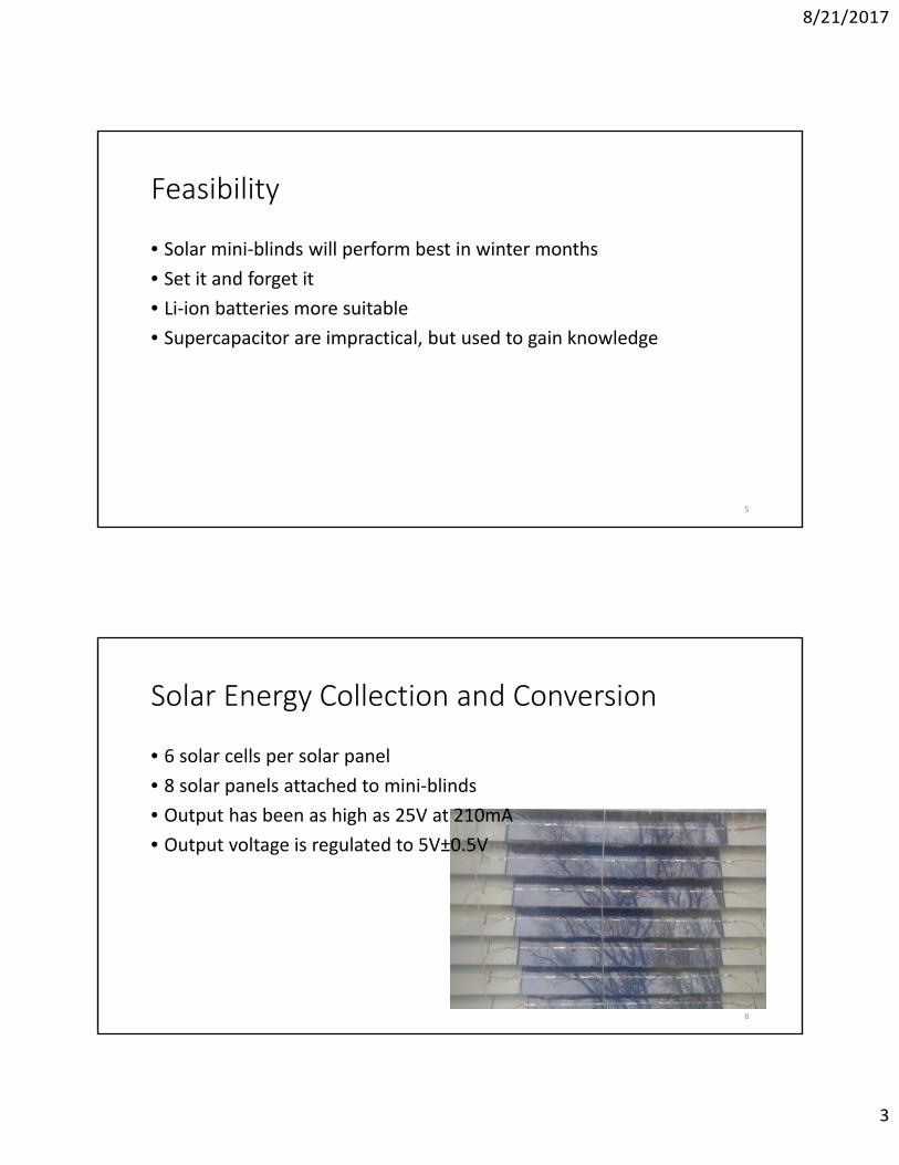
Solar Energy Collection and Conversion
• 6 solar cells per solar panel
• 8 solar panels attached to mini‐blinds
• Output has been as high as 25V at 210mA
• Output voltage is regulated to 5V±0.5V
6
8/21/2017
4
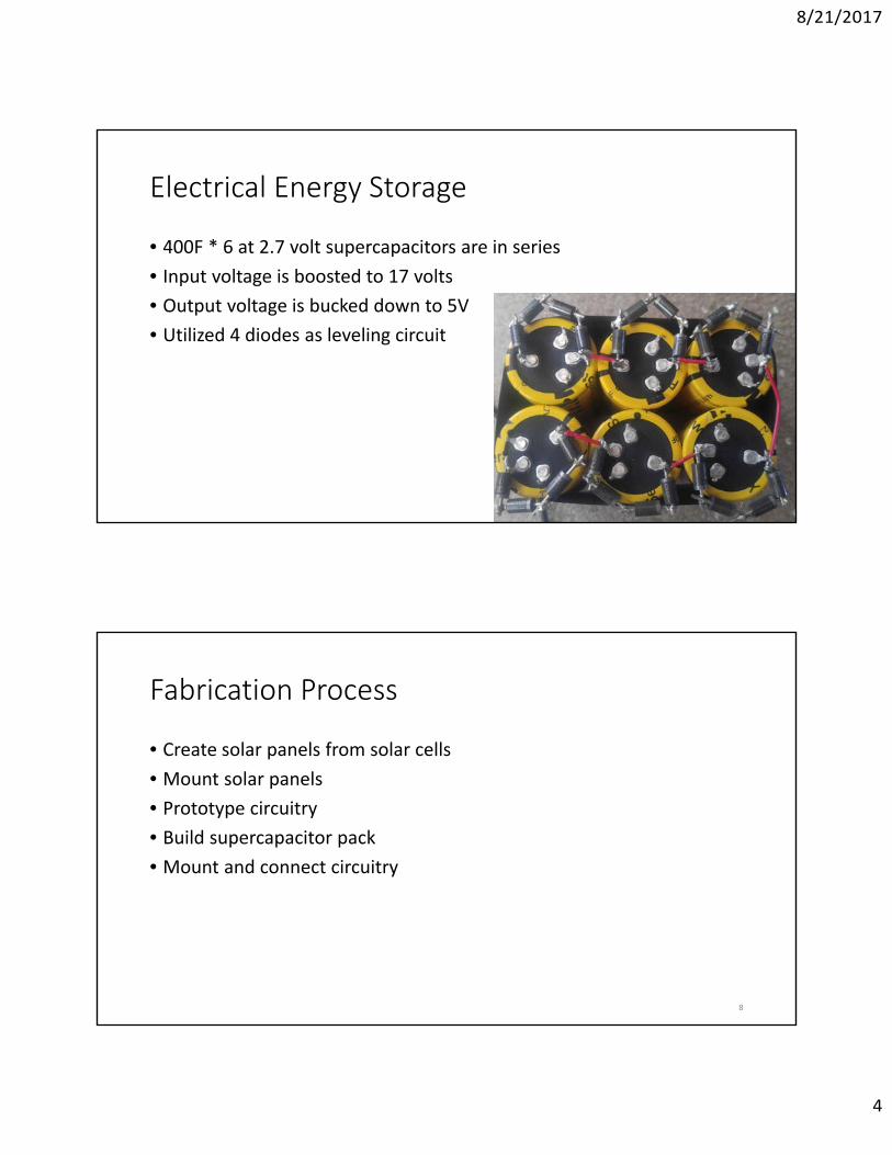
Electrical Energy Storage
• 400F * 6 at 2.7 volt supercapacitors are in series
• Input voltage is boosted to 17 volts
• Output voltage is bucked down to 5V
• Utilized 4 diodes as leveling circuit
7
Fabrication Process
• Create solar panels from solar cells
• Mount solar panels
• Prototype circuitry
• Build supercapacitor pack
• Mount and connect circuitry
8
8/21/2017
5
Solar Cells
• Silicon Polycrystalline cells were chosen
• Cheaper than monocrystalline
• Produce less power and waste to manufacture
• About 17% efficiency
• 0.6% efficiency decay per year
• 0.6V open circuit voltage per cell
• 200mA short circuit current per cell
9
Storage Element‐Supercapacitors
• Expensive, relatively high capacity compared to normal capacitors
• Low no‐load leakage current, 0.85mA after 72 hours
• Can be stored for several days with usable energy
• Requires leveling circuit for series configuration
10
8/21/2017
6
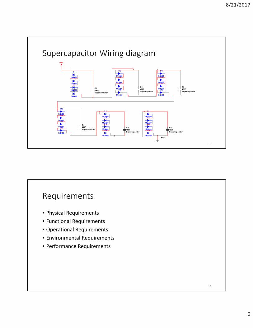
Supercapacitor Wiring diagram
11
C1400FSupercapacitor
D1
1N5400D2
1N5400D3
1N5400D4
1N5400
C2400FSupercapacitor
D5
1N5400D6
1N5400D7
1N5400D8
1N5400
C3400FSupercapacitor
D9
1N5400D10
1N5400D11
1N5400D12
1N5400
C4400FSupercapacitor
D13
1N5400D14
1N5400D15
1N5400D16
1N5400
C5400FSupercapacitor
D17
1N5400D18
1N5400D19
1N5400D20
1N5400
C6400FSupercapacitor
D21
1N5400D22
1N5400D23
1N5400D24
1N5400NEG
Pos
Requirements
• Physical Requirements
• Functional Requirements
• Operational Requirements
• Environmental Requirements
• Performance Requirements
12
8/21/2017
7
Circuit Design
• LM2678T simple switcher for buck converter• 8‐30 volts in, 5 volts out, max 5A
• LM2585 simple switcher for boost converter• 4‐40 volts in, max 65 volts out, 3A max output
• Utilized standard USB connectors for inputs and outputs
13
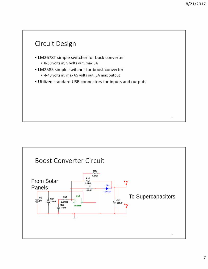
Boost Converter Circuit
14
V15V
Rb1
2.94kΩ
Rb2
1.5kΩRb3
19.1kΩ
Cb1150µF Cb2
330µFCb3470nF
Lb1
68µH
Db1
1N4447
Ub1
lm2585
123 4
5
Pos
Neg
To Supercapacitors
From SolarPanels
8/21/2017
8
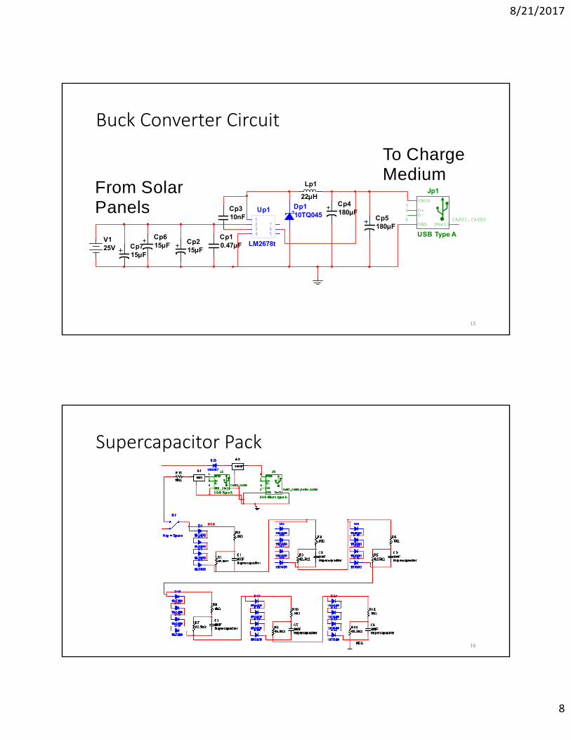
Buck Converter Circuit
15
V125V
Cp10.47µFCp2
15µF
Cp310nF
Lp1
22µHCp4180µF
Cp5180µF
Dp110TQ045
Up1
LM2678t
1234 5
67
Jp1
USB Type A
VBUS1
D+3
D-2
GND4
ShellCASE1,CASE2
Cp615µFCp7
15µF
From SolarPanels
To ChargeMedium
Supercapacitor Pack
16
8/21/2017
9
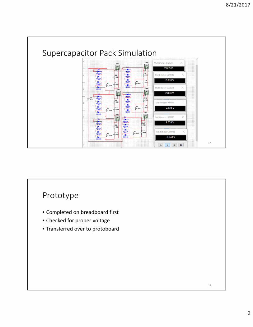
Supercapacitor Pack Simulation
17
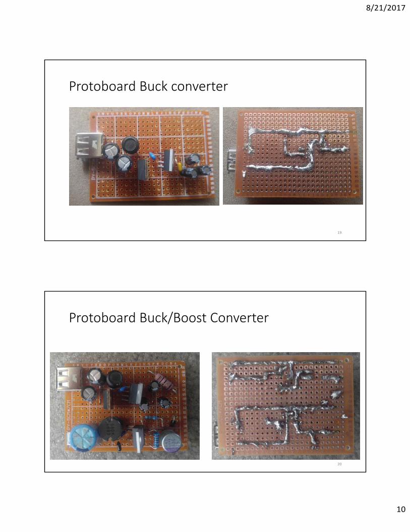
Prototype
• Completed on breadboard first
• Checked for proper voltage
• Transferred over to protoboard
18
8/21/2017
10
Protoboard Buck converter
19
Protoboard Buck/Boost Converter
20
8/21/2017
11
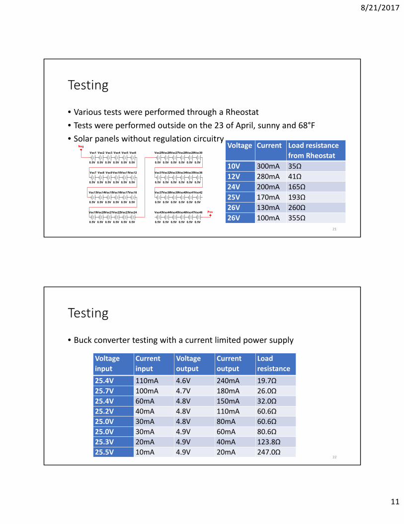
Testing
• Various tests were performed through a Rheostat
• Tests were performed outside on the 23 of April, sunny and 68°F
• Solar panels without regulation circuitryVoltage Current Load resistance
from Rheostat
10V 300mA 35Ω
12V 280mA 41Ω
24V 200mA 165Ω
25V 170mA 193Ω
26V 130mA 260Ω
26V 100mA 355Ω
21
Vsc1
0.5V
Vsc2
0.5V
Vsc3
0.5V
Vsc4
0.5V
Vsc5
0.5V
Vsc6
0.5V
Vsc7
0.5V
Vsc8
0.5V
Vsc9
0.5V
Vsc10
0.5V
Vsc11
0.5V
Vsc12
0.5V
Vsc13
0.5V
Vsc14
0.5V
Vsc15
0.5V
Vsc16
0.5V
Vsc17
0.5V
Vsc18
0.5V
Vsc19
0.5V
Vsc20
0.5V
Vsc21
0.5V
Vsc22
0.5V
Vsc23
0.5V
Vsc24
0.5V
Vsc25
0.5V
Vsc26
0.5V
Vsc27
0.5V
Vsc28
0.5V
Vsc29
0.5V
Vsc30
0.5V
Vsc31
0.5V
Vsc32
0.5V
Vsc33
0.5V
Vsc34
0.5V
Vsc35
0.5V
Vsc36
0.5V
Vsc37
0.5V
Vsc38
0.5V
Vsc39
0.5V
Vsc40
0.5V
Vsc41
0.5V
Vsc42
0.5V
Vsc43
0.5V
Vsc44
0.5V
Vsc45
0.5V
Vsc46
0.5V
Vsc47
0.5V
Vsc48
0.5V
Pos
Neg
Testing
• Buck converter testing with a current limited power supply
Voltage
input
Current
input
Voltage
output
Current
output
Load
resistance
25.4V 110mA 4.6V 240mA 19.7Ω
25.7V 100mA 4.7V 180mA 26.0Ω
25.4V 60mA 4.8V 150mA 32.0Ω
25.2V 40mA 4.8V 110mA 60.6Ω
25.0V 30mA 4.8V 80mA 60.6Ω
25.0V 30mA 4.9V 60mA 80.6Ω
25.3V 20mA 4.9V 40mA 123.8Ω
25.5V 10mA 4.9V 20mA 247.0Ω22
8/21/2017
12
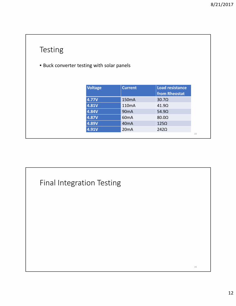
Testing
• Buck converter testing with solar panels
Voltage Current Load resistance
from Rheostat
4.77V 150mA 30.7Ω
4.81V 110mA 41.9Ω
4.84V 90mA 54.9Ω
4.87V 60mA 80.0Ω
4.89V 40mA 125Ω
4.91V 20mA 242Ω23
Final Integration Testing
24
8/21/2017
13
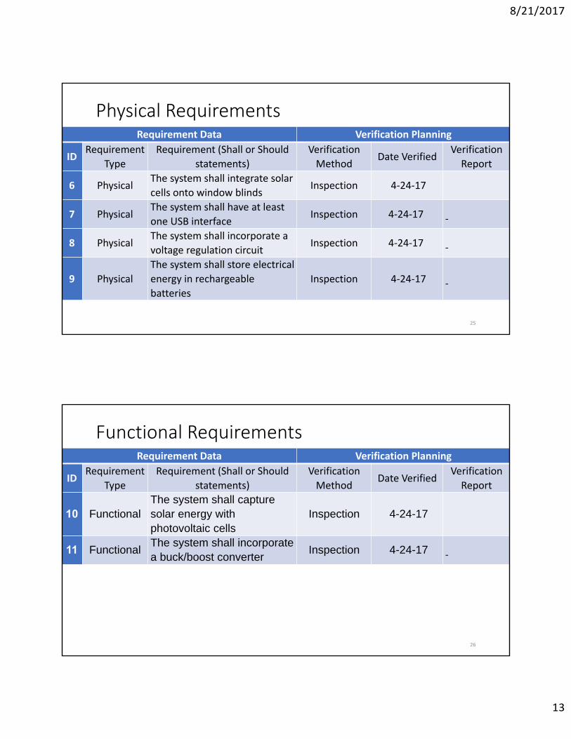
Physical RequirementsRequirement Data Verification Planning
IDRequirement
Type
Requirement (Shall or Should
statements)
Verification
MethodDate Verified
Verification
Report
6 PhysicalThe system shall integrate solar
cells onto window blindsInspection 4‐24‐17
7 PhysicalThe system shall have at least
one USB interfaceInspection 4‐24‐17
8 PhysicalThe system shall incorporate a
voltage regulation circuitInspection 4‐24‐17
9 Physical
The system shall store electrical
energy in rechargeable
batteries
Inspection 4‐24‐17
25
Functional RequirementsRequirement Data Verification Planning
IDRequirement
Type
Requirement (Shall or Should
statements)
Verification
MethodDate Verified
Verification
Report
10 FunctionalThe system shall capture solar energy with photovoltaic cells
Inspection 4-24-17
11 FunctionalThe system shall incorporate a buck/boost converter
Inspection 4-24-17
26
8/21/2017
14
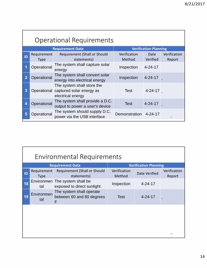
Operational RequirementsRequirement Data Verification Planning
IDRequirement
Type
Requirement (Shall or Should
statements)
Verification
Method
Date
Verified
Verification
Report
1 OperationalThe system shall capture solar energy
Inspection 4-24-17
2 OperationalThe system shall convert solar energy into electrical energy
Inspection 4-24-17
3 OperationalThe system shall store the captured solar energy as electrical energy
Test 4-24-17
4 OperationalThe system shall provide a D.C. output to power a user's device
Test 4-24-17
5 OperationalThe system should supply D.C. power via the USB interface
Demonstration 4-24-1727
Environmental RequirementsRequirement Data Verification Planning
IDRequirement
Type
Requirement (Shall or Should
statements)
Verification
MethodDate Verified
Verification
Report
18Environmen
talThe system shall be exposed to direct sunlight
Inspection 4-24-17
19Environmen
tal
The system shall operate between 60 and 80 degrees F
Test 4-24-17
28
8/21/2017
15
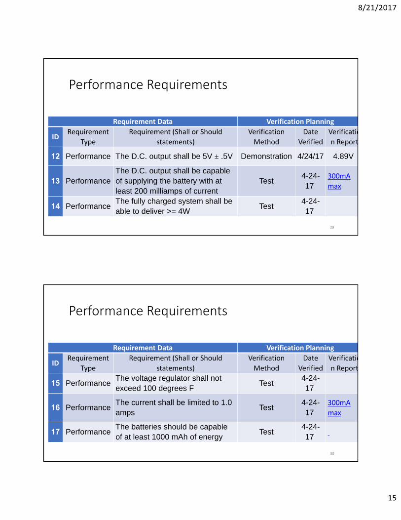
Performance Requirements
Requirement Data Verification Planning
IDRequirement
Type
Requirement (Shall or Should
statements)
Verification
Method
Date
Verified
Verificatio
n Report
12 Performance The D.C. output shall be 5V ± .5V Demonstration 4/24/17 4.89V
13 PerformanceThe D.C. output shall be capable of supplying the battery with at least 200 milliamps of current
Test4-24-17
300mA
max
14 PerformanceThe fully charged system shall be able to deliver >= 4W
Test4-24-17
29
Performance Requirements
Requirement Data Verification Planning
IDRequirement
Type
Requirement (Shall or Should
statements)
Verification
Method
Date
Verified
Verificatio
n Report
15 PerformanceThe voltage regulator shall not exceed 100 degrees F
Test4-24-17
16 PerformanceThe current shall be limited to 1.0 amps
Test4-24-17
300mA
max
17 PerformanceThe batteries should be capable of at least 1000 mAh of energy
Test4-24-17
30
8/21/2017
16
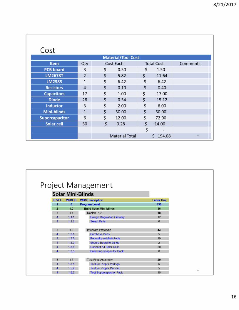
CostMaterial/Tool Cost
Item Qty Cost Each Total Cost Comments
PCB board 3 $ 0.50 $ 1.50
LM2678T 2 $ 5.82 $ 11.64
LM2585 1 $ 6.42 $ 6.42
Resistors 4 $ 0.10 $ 0.40
Capacitors 17 $ 1.00 $ 17.00
Diode 28 $ 0.54 $ 15.12
Inductor 3 $ 2.00 $ 6.00
Mini‐blinds 1 $ 50.00 $ 50.00
Supercapacitor 6 $ 12.00 $ 72.00
Solar cell 50 $ 0.28 $ 14.00
$ ‐
Material Total $ 194.08 31
Project Management
32
8/21/2017
17
Project Management
33
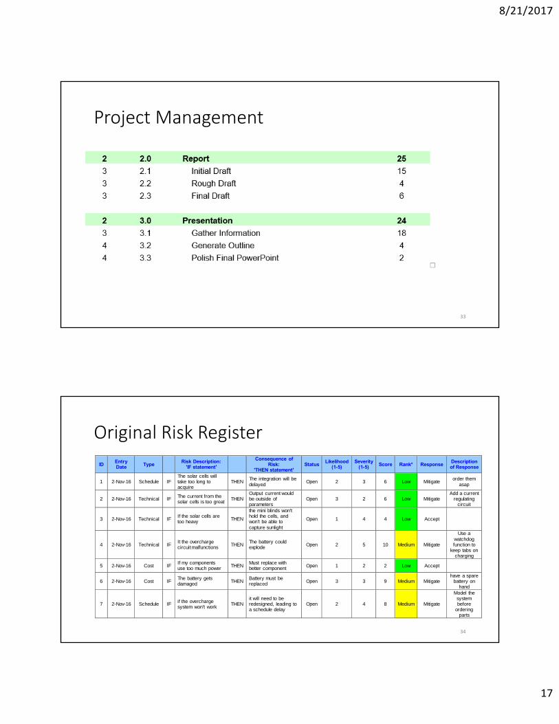
Original Risk Register
34
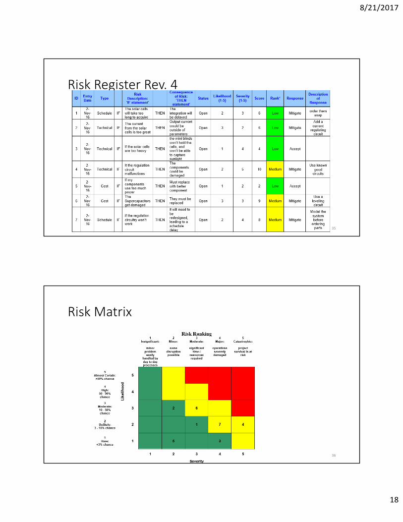
ID Entry Date Type
Risk Description: 'IF statement'
Consequence of Risk:
'THEN statement' Status
Likelihood (1-5)
Severity (1-5) Score Rank* Response
Description of Response
1 2-Nov-16 Schedule IF The solar cells will take too long to acquire
THEN The integration will be delayed
Open 2 3 6 Low Mitigate order them
asap
2 2-Nov-16 Technical IF The current from the solar cells is too great
THEN Output current would be outside of parameters
Open 3 2 6 Low Mitigate Add a current
regulating circuit
3 2-Nov-16 Technical IF If the solar cells are too heavy THEN
the mini blinds won't hold the cells, and won't be able to capture sunlight
Open 1 4 4 Low Accept
4 2-Nov-16 Technical IF It the overcharge circuit malfunctions THEN
The battery could explode Open 2 5 10 Medium Mitigate
Use a watchdog function to
keep tabs on charging
5 2-Nov-16 Cost IF If my components use too much power THEN
Must replace with better component Open 1 2 2 Low Accept
6 2-Nov-16 Cost IF The battery gets damaged THEN
Battery must be replaced Open 3 3 9 Medium Mitigate
have a spare battery on
hand
7 2-Nov-16 Schedule IF if the overcharge system won't work
THEN it will need to be redesigned, leading to a schedule delay
Open 2 4 8 Medium Mitigate
Model the system before
ordering parts
8/21/2017
18
Risk Register Rev. 4
35
Risk Matrix
36
8/21/2017
19
Conclusion
• Solar panels would work better on a mobile platform
• Li‐ion batteries would be more suitable
• Learned valuable information about supercapacitors
• Gained knowledge on solar energy
37
References
38
Buchmann, I. (2017, Feburary 19). Bu‐209: How does a Supercapacitor Work. Retrieved from Battery University: http://batteryuniversity.com/learn/article/whats_the_role_of_the_supercapacitor
Energy, U. D. (2017, Feburary 19). Frequently Asked Question. Retrieved from U.S. Energy Information Administration: https://www.eia.gov/tools/faqs/faq.cfm?id=427&t=3
M. Ameer Ur Rehman Sheikh, M. S. (2014). Voltage Balancing of Supercapacitors String using Rectifier Diodes: Analytical and Simulation Ap‐proach. International Journal of Scientific & Engineering Research, 1290‐1295.
Maehium, M. A. (2017, Feburary 19). The Real Lifespan of Solar Panels. Retrieved from energy informative: http://energyinformative.org/lifespan‐solar‐panels/
8/21/2017
20
Questions/Comments?
39
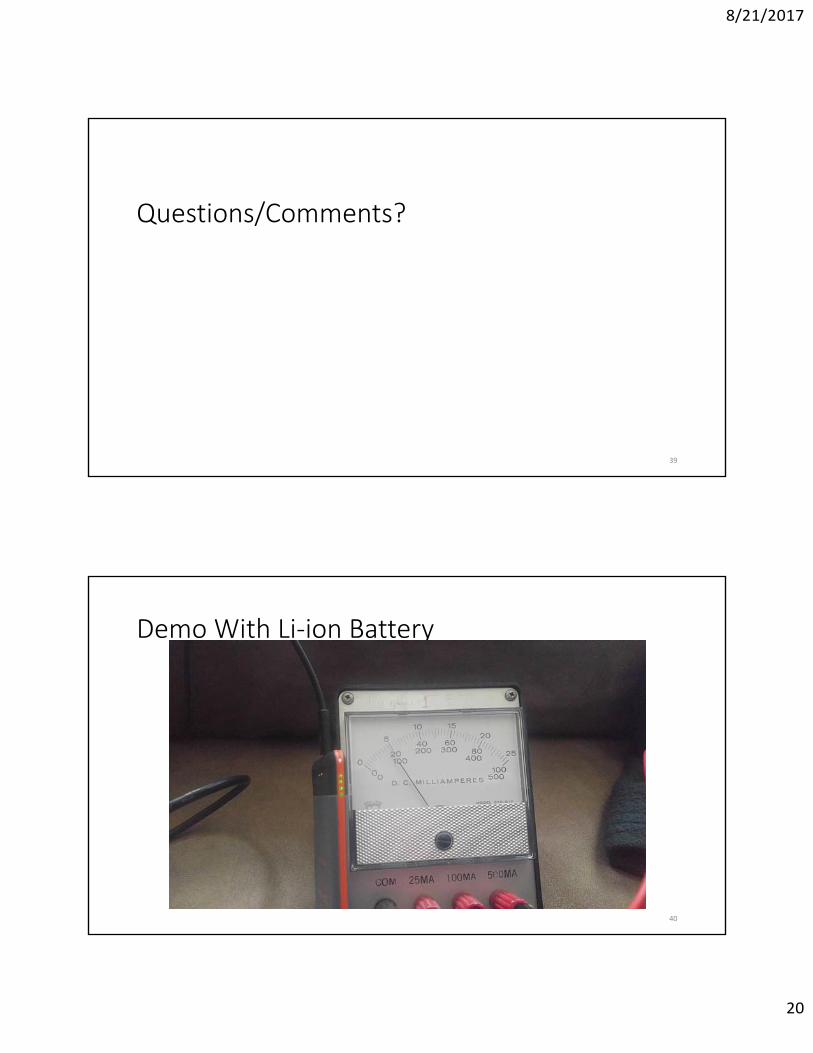
Demo With Li‐ion Battery
40
8/21/2017
21
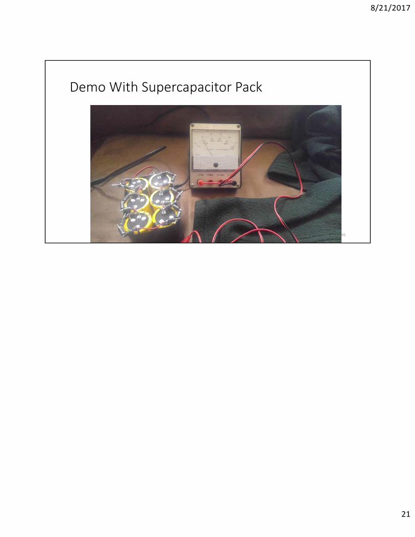
Demo With Supercapacitor Pack
41