Embed Size (px)
Citation preview

TOPAZ Total HardnessOperator’s Manual
TOPAZ Total Hardness
SOL-96.110.051 / 250821

© 2021, Seres OL SAS, France, all rights reserved.
The information contained in this document is subject to change without notice.
Customer SupportSeres OL and its representatives maintain a fully trained staff of technical specialists around the world. For any technical question, contact your nearest Seres OL representa-tive, or the manufacturer:
Seres OL SASZA de la Sipière219, Avenue de ProvenceFR-13730 Saint-VictoretFrance
Internet: www.seres-ol.comE-mail: [email protected]
Document Status
Title: TOPAZ Total Hardness Operator’s Manual
ID: SOL-96.110.051
Revision Issue
00 August 2021 First edition

SOL-96.110.051 / 250821
TOPAZ Total Hardness
1
Table of Contents
1. Safety Instructions . . . . . . . . . . . . . . . . . . . . . . . . . . . . . . . . . . . . . . . . . . . . . 31.1. Warning Notices . . . . . . . . . . . . . . . . . . . . . . . . . . . . . . . . . . . . . . . . . . . . . . . . 41.2. General Safety Regulations . . . . . . . . . . . . . . . . . . . . . . . . . . . . . . . . . . . . . . . 61.3. Handling Precautions . . . . . . . . . . . . . . . . . . . . . . . . . . . . . . . . . . . . . . . . . . . . 71.4. International Symbols Used . . . . . . . . . . . . . . . . . . . . . . . . . . . . . . . . . . . . . . . 72. Product Description . . . . . . . . . . . . . . . . . . . . . . . . . . . . . . . . . . . . . . . . . . . . 82.1. Instrument Specifications . . . . . . . . . . . . . . . . . . . . . . . . . . . . . . . . . . . . . . . . . 92.2. Instrument Overview . . . . . . . . . . . . . . . . . . . . . . . . . . . . . . . . . . . . . . . . . . . . . 123. Installation . . . . . . . . . . . . . . . . . . . . . . . . . . . . . . . . . . . . . . . . . . . . . . . . . . . . 133.1. Before Installation . . . . . . . . . . . . . . . . . . . . . . . . . . . . . . . . . . . . . . . . . . . . . . . 133.2. Mounting the Wall Cabinet . . . . . . . . . . . . . . . . . . . . . . . . . . . . . . . . . . . . . . . . 133.3. Hydraulic Connections . . . . . . . . . . . . . . . . . . . . . . . . . . . . . . . . . . . . . . . . . . . 133.4. Electrical Connections. . . . . . . . . . . . . . . . . . . . . . . . . . . . . . . . . . . . . . . . . . . . 143.4.1 Connections on I/O Board . . . . . . . . . . . . . . . . . . . . . . . . . . . . . . . . . . . . . . . 153.4.2 Cable thicknesses . . . . . . . . . . . . . . . . . . . . . . . . . . . . . . . . . . . . . . . . . . . . . 193.4.3 AC power . . . . . . . . . . . . . . . . . . . . . . . . . . . . . . . . . . . . . . . . . . . . . . . . . . . . 203.4.4 Jbus via RS485 . . . . . . . . . . . . . . . . . . . . . . . . . . . . . . . . . . . . . . . . . . . . . . . 213.4.5 Jbus via TCP/IP (Option) . . . . . . . . . . . . . . . . . . . . . . . . . . . . . . . . . . . . . . . . 224. Startup . . . . . . . . . . . . . . . . . . . . . . . . . . . . . . . . . . . . . . . . . . . . . . . . . . . . . . . 234.1. Installing the Reagent Bottles . . . . . . . . . . . . . . . . . . . . . . . . . . . . . . . . . . . . . . 234.2. Starting Sample Flow . . . . . . . . . . . . . . . . . . . . . . . . . . . . . . . . . . . . . . . . . . . . 244.3. Priming the Reagent Tubes. . . . . . . . . . . . . . . . . . . . . . . . . . . . . . . . . . . . . . . . 254.4. Run-in Period . . . . . . . . . . . . . . . . . . . . . . . . . . . . . . . . . . . . . . . . . . . . . . . . . . 284.5. Manual Measurement . . . . . . . . . . . . . . . . . . . . . . . . . . . . . . . . . . . . . . . . . . . . 284.6. Programming. . . . . . . . . . . . . . . . . . . . . . . . . . . . . . . . . . . . . . . . . . . . . . . . . . . 285. Operation . . . . . . . . . . . . . . . . . . . . . . . . . . . . . . . . . . . . . . . . . . . . . . . . . . . . . 295.1. Access Levels . . . . . . . . . . . . . . . . . . . . . . . . . . . . . . . . . . . . . . . . . . . . . . . . . . 295.2. User Interface . . . . . . . . . . . . . . . . . . . . . . . . . . . . . . . . . . . . . . . . . . . . . . . . . . 306. Maintenance. . . . . . . . . . . . . . . . . . . . . . . . . . . . . . . . . . . . . . . . . . . . . . . . . . . 316.1. Maintenance Schedule . . . . . . . . . . . . . . . . . . . . . . . . . . . . . . . . . . . . . . . . . . . 316.2. Stop of Operation for Maintenance . . . . . . . . . . . . . . . . . . . . . . . . . . . . . . . . . . 326.3. Replacing Reagents . . . . . . . . . . . . . . . . . . . . . . . . . . . . . . . . . . . . . . . . . . . . . 346.4. Replacing Sample Tubes . . . . . . . . . . . . . . . . . . . . . . . . . . . . . . . . . . . . . . . . . 366.5. Replacing Peristaltic Pump Tubes . . . . . . . . . . . . . . . . . . . . . . . . . . . . . . . . . . 376.6. Manual Measurement and Calibration . . . . . . . . . . . . . . . . . . . . . . . . . . . . . . . 396.6.1 Manual Measurement . . . . . . . . . . . . . . . . . . . . . . . . . . . . . . . . . . . . . . . . . . 40

SOL-96.110.051 / 250821
TOPAZ Total Hardness
2
6.6.2 Standard Calibration . . . . . . . . . . . . . . . . . . . . . . . . . . . . . . . . . . . . . . . . . . . . 416.7. Longer Stop of Operation. . . . . . . . . . . . . . . . . . . . . . . . . . . . . . . . . . . . . . . . . . 417. Configuration of the Analyzer . . . . . . . . . . . . . . . . . . . . . . . . . . . . . . . . . . . . . 428. Troubleshooting. . . . . . . . . . . . . . . . . . . . . . . . . . . . . . . . . . . . . . . . . . . . . . . . 468.1. What To Do If... . . . . . . . . . . . . . . . . . . . . . . . . . . . . . . . . . . . . . . . . . . . . . . . . . 468.2. List of Errors and Alarms . . . . . . . . . . . . . . . . . . . . . . . . . . . . . . . . . . . . . . . . . . 508.3. Saving Diagnostic Data to USB Stick. . . . . . . . . . . . . . . . . . . . . . . . . . . . . . . . . 589. Notes . . . . . . . . . . . . . . . . . . . . . . . . . . . . . . . . . . . . . . . . . . . . . . . . . . . . . . . . . 59
SOL-96.110.051 / 250821
TOPAZ Total HardnessSafety Instructions
3
Operator’s ManualThis document describes the main steps for instrument setup, operation and maintenance.
1. Safety Instructions
General The instructions included in this chapter explain the potential risks associated with instrument operation and provide important safety practices designed to minimize these risks.If you carefully follow the information contained in this chapter, you can protect yourself from hazards and create a safer work environ-ment.More safety instructions are given throughout this manual, at the respective locations where observation is most important. Strictly follow all safety instructions in this publication.
Targetaudience
Operator: Qualified person who uses the equipment for its intended purpose.Instrument operation requires thorough knowledge of applications, instrument functions and software as well as all applicable safety rules and regulations.
OM location Keep the Operator’s Manual in proximity of the instrument.
Qualification,training
To be qualified for instrument installation and operation, you must: read and understand the instructions in this manual as well as
the Material Safety Data Sheets and know the relevant safety rules and regulations.

SOL-96.110.051 / 250821
TOPAZ Total HardnessSafety Instructions
4
1.1. Warning NoticesThe signal words and symbols used for safety-related notices have the following meaning:
DANGER
Your life or physical wellbeing are in serious danger if such warnings are ignored. Follow the prevention instructions carefully.
WARNING
Severe injuries or damage to the equipment can occur if such warnings are ignored. Follow the prevention instructions carefully.
CAUTION
Damage to the equipment, minor injury, malfunctions or incorrect process values can be the consequence if such warnings are ignored. Follow the prevention instructions carefully.
Mandatorysigns
The mandatory signs in this manual have the following meaning:
Safety goggles
Safety gloves

SOL-96.110.051 / 250821
TOPAZ Total HardnessSafety Instructions
5
Warning signs The warning signs in this manual have the following meaning:
Electrical shock hazard
Corrosive
Harmful to health
Flammable
Hot surface
General warning
SOL-96.110.051 / 250821
TOPAZ Total HardnessSafety Instructions
6
1.2. General Safety RegulationsSpare parts
anddisposables
Use only official Seres OL spare parts and consumables. If other parts are used during the normal warranty period, the manufacturer’s warranty is voided.
Modifications Modifications and instrument upgrades shall only be carried out by an authorized service technician. Seres OL will not accept responsi-bility for any claim resulting from unauthorized modification or alter-ation.
Localregulations
All wiring and connections (electrical, hydraulic) may only be carried out by qualified personnel and in accordance with the local regula-tions of the respective country.
WARNING
Electrical shock hazard If proper operation is no longer possible, the instrument must
be disconnected from all power lines, and measures must be taken to prevent inadvertent operation.
To prevent from electrical shock, always make sure that the protective earth wire is connected.
Service shall be performed by authorized personnel only. Whenever electronic service is required, disconnect the
instrument from power.
WARNING
Chemical exposure hazard When handling chemicals or performing maintenance work
on hydraulic parts of the analyzer, wear suitable protective equipment.
Read the Material Safety Datasheets (MSDS) of the chemicals carefully.
WARNING
Do not use this instrument in presence of flammable liquids or vapors as this may pose a safety hazard.

SOL-96.110.051 / 250821
TOPAZ Total HardnessSafety Instructions
7
1.3. Handling PrecautionsPosition the box correctly (up/down). Carefully unpack the analyzer and check it for visible damage. If the analyzer shows any visible damage, do not connect it to power and contact customer service immediately.
1.4. International Symbols UsedThe symbols found on the instrument have the following meaning:
Electrical fuse
Ground
Equipotentiality
Alternating current
Hot surface
General attention
Electrical hazard
SOL-96.110.051 / 250821
TOPAZ Total HardnessProduct Description
8
2. Product Description
Applicationrange
The TOPAZ Total Hardness is a complete monitoring system for the measurement of total hardness TH in potable water, demineralized water production and process water.
Measuringprinciple
Titration of the coloration formed between hydroxynaphthol blue, calcium and magnesium at pH 10 with EDTA.
Configurations The instrument is available in the following configurations: Measuring ranges:
– TOPAZ Total Hardness LR:5–50 ppm CaCO3
– TOPAZ Total Hardness HR:10–100 ppm CaCO315–300 ppm CaCO330–600 ppm CaCO3
Available with one, two, four or six measuring channels (common measuring range)
Signaloutputs
Two signal outputs per measuring channel.Current loop: 4–20 mA
Relays Five potential-free contacts per measuring channel with the following functions: two thresholds (high/high, low/high or low/low) sample flow alarm indication of the active measuring channel maintenance indication
Maximum load: 1 A/24 V
Alarm relay One summary alarm for “analyzer failure”.Maximum load: 1 A/24 V
Digital inputs One digital input per measuring channel to select the active sample stream and one digital input to stop measurement.To use the digital inputs, select control mode 3 (see Configuration of the Analyzer, p. 42).

SOL-96.110.051 / 250821
TOPAZ Total HardnessProduct Description
9
2.1. Instrument Specifications
Power supply Voltage:
Power consumption:
110–240 VAC50/60 Hz150 VA typical, 300 VA maximum
Environmentalconditions
Temperature:Relative humidity:Pollution level:Installation category:Maximum altitude:
5–40 °C10% to 80%2II2000 m
Do not use this instrument in presence of flammable liquids or gases.Protect it from bad weather, humidity, corrosive substances and dust.
Processconnections
Sample inlet:Sample outlet:
Sample outlet waste:
1/4” BSP Fsoft tubing D INT 9 (single channel)soft tubing D INT 19 (multi channel)soft tubing D INT 12
Samplerequirements
Flow rate:Temperature:Inlet pressure:Outlet pressure:Particle size:
min. 30 l /h (opt. 40 l/h)5–40 °C0.1–2 barpressure-free<20 µm
Air cleaning Inlet:Required air flow:
6 mm tubing50 l/h minimum of clean and dry air
Air cleaning can be used to protect the analyzer from a corrosive environment.

SOL-96.110.051 / 250821
TOPAZ Total HardnessProduct Description
10
Measuringrange
Instrument variant:Range:Limit of detection:Repeatability:Accuracy:
LR5–50 ppm CaCO3≤5 ppm<±5% FS<±5% FS
Instrument variant:Range selection:
Limit of detection:
Repeatability:Accuracy:
HR10–100 ppm CaCO3 or15–300 ppm CaCO3 or30–600 ppm CaCO3<10 ppm (10–100 ppm)<15 ppm (15–300 ppm)<30 ppm (30–600 ppm)<±5% FS (all ranges)<±5% FS (all ranges)
SOL-96.110.051 / 250821
TOPAZ Total HardnessProduct Description
11
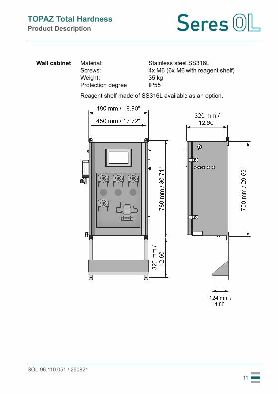
Wall cabinet Material:Screws:Weight:Protection degree
Stainless steel SS316L4x M6 (6x M6 with reagent shelf)35 kgIP55
Reagent shelf made of SS316L available as an option.

SOL-96.110.051 / 250821
TOPAZ Total HardnessProduct Description
12
2.2. Instrument Overview
ABCDEFG
HIJK
Power switchTouchscreenCable glandsPeristaltic pumpsPhotometerAir cleaning inletPressure reducing deviceCalibration vesselSample inlet tapReagent tubesDrain
BA
E
GH
F
I
KJ
D
C

SOL-96.110.051 / 250821
TOPAZ Total HardnessInstallation
13
3. Installation
3.1. Before InstallationUnpacking Carefully unpack the analyzer and check it for visible damage.
On-siterequirements
Verify the electrical and hydraulic connections available at the instal-lation site against the requirements in Instrument Specifications, p. 9.
3.2. Mounting the Wall CabinetMounting
requirementsMount the instrument in vertical position. The display should be at eye level to simplify operation and maintenance.For dimensions see drawing on 11.
Reagentbottles
Reagent bottles must be stored outside the analyzer. Provide a suitable storage area near the analyzer.As an option, a reagent shelf is available that can be installed directly below the analyzer.
3.3. Hydraulic ConnectionsFor hydraulic connections, refer to the separate hydraulic scheme.

SOL-96.110.051 / 250821
TOPAZ Total HardnessInstallation
14
3.4. Electrical Connections
WARNING
Risk of electrical shockAlways turn off power before manipulating electric parts. Only operate the instrument from a power outlet which has a protec-tive earth connection.
Overview ofelectrical
connections
1) In multi-channel instruments, there is an I/O board for each measuring channel. The I/O boards are arranged from left to right in ascending order according to their channel number.
ABC
I/O board1) (relays, analog signal outputs, digital inputs)RS485 interfaceAC power
A
BC

SOL-96.110.051 / 250821
TOPAZ Total HardnessInstallation
15
3.4.1 Connections on I/O BoardConnection
scheme
Note: • Relays OUT_DIG1 and OUT_DIG8 are used to control internal
components of the analyzer. Do not connect anything else to these contacts.
• Analog signal output OUT_ANA2 is reserved for customized versions of the analyzer that provide a second value.
IN_DIG1
IN_DIG2
OUT_ANA1
OUT_DIG5
+24 V
J7
J9
J8
+24 V
+-
OUT_ANA2 +-
16
1
1
9
8
1
OUT_DIG6
OUT_DIG7
OUT_DIG8
OUT_DIG1
OUT_DIG2
OUT_DIG3
OUT_DIG4

SOL-96.110.051 / 250821
TOPAZ Total HardnessInstallation
16
Digital inputs
Both digital inputs can be used with dry (potential-free) or wet contacts (0/+24 V).
Note: It is strongly recommended to use dry contacts to avoid electrical problems.
If dry contacts are used, connect them to terminals 1/2 and 4/5 of connector J8 as shown in the connection scheme.If control is provided by wet contacts, connect the reference to pin 3 (6) and the selection voltage 0/+24 V to pin 2 (5) of connector J8. Leave pins 1 and 4 unconnected.
Analog signaloutputs
(4–20 mA)
Name Available on DescriptionIN_DIG1 all measuring
channelsActivates or deactivates the measuring channel. Open contact:
Measuring channel will be measured according to the programmed channel sequence.
Closed contact:Measuring channel will be skipped and the user will be informed via a message on the screen.
IN_DIG2 channel 1 Closing the contact will complete the current measurement cycle and then stop the measurement.
Name Available on DescriptionOUT_ANA1 all measuring
channelsTotal hardness TH.4 mA corresponds to low range measurement and 20 mA to high range measurement.
OUT_ANA2 all measuring channels
Reserved.
SOL-96.110.051 / 250821
TOPAZ Total HardnessInstallation
17
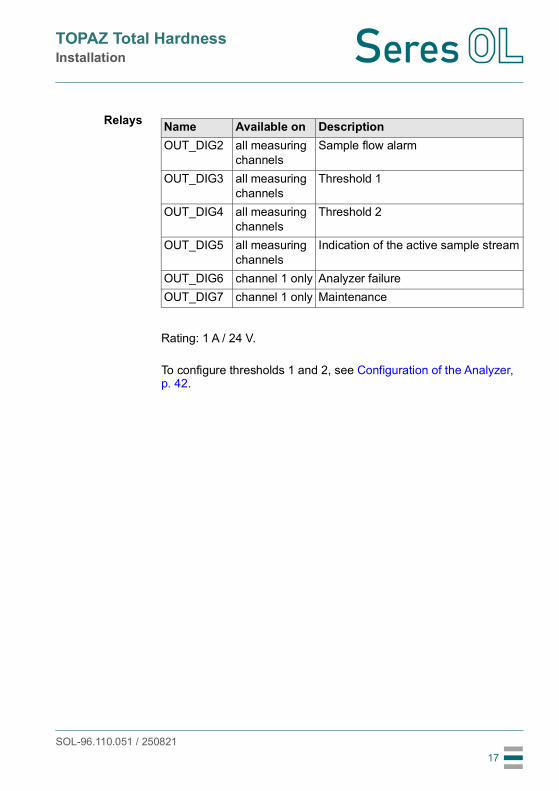
Relays
Rating: 1 A / 24 V.
To configure thresholds 1 and 2, see Configuration of the Analyzer, p. 42.
Name Available on DescriptionOUT_DIG2 all measuring
channelsSample flow alarm
OUT_DIG3 all measuring channels
Threshold 1
OUT_DIG4 all measuring channels
Threshold 2
OUT_DIG5 all measuring channels
Indication of the active sample stream
OUT_DIG6 channel 1 only Analyzer failureOUT_DIG7 channel 1 only Maintenance

SOL-96.110.051 / 250821
TOPAZ Total HardnessInstallation
18
Settingjumpers
Relays OUT_DIG2 to OUT_DIG7 can be configured as normally open or normally closed by setting the corresponding jumpers on the I/O board.The default setting is normally open (jumper in the right position).
A Location of jumpers on I/O board
Name of jumper RelayJP8 OUT_DIG2JP9 OUT_DIG3JP10 OUT_DIG4JP11 OUT_DIG5JP12 OUT_DIG6JP13 OUT_DIG7
A
SOL-96.110.051 / 250821
TOPAZ Total HardnessInstallation
19
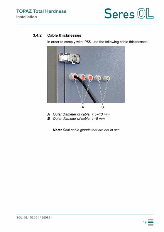
3.4.2 Cable thicknessesIn order to comply with IP55, use the following cable thicknesses:
Note: Seal cable glands that are not in use.
AB
Outer diameter of cable: 7.5–13 mmOuter diameter of cable: 4–8 mm
A B
SOL-96.110.051 / 250821
TOPAZ Total HardnessInstallation
20
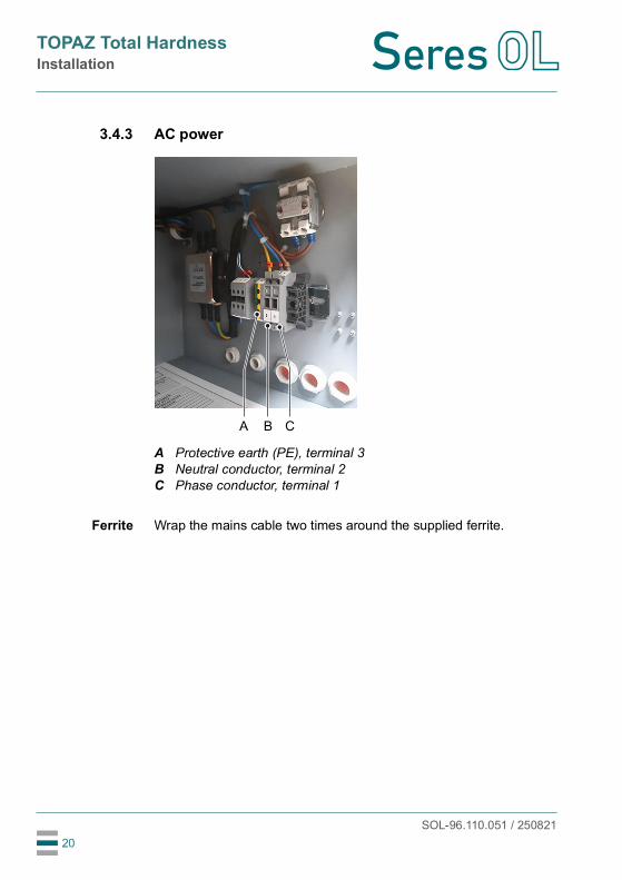
3.4.3 AC power
Ferrite Wrap the mains cable two times around the supplied ferrite.
ABC
Protective earth (PE), terminal 3Neutral conductor, terminal 2Phase conductor, terminal 1
A B C

SOL-96.110.051 / 250821
TOPAZ Total HardnessInstallation
21
3.4.4 Jbus via RS485
Terminals Terminal 1: data B (+), terminal 2: data A (-).
A RS485 interface
A
SOL-96.110.051 / 250821
TOPAZ Total HardnessInstallation
22
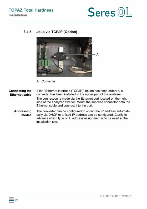
3.4.5 Jbus via TCP/IP (Option)
Connecting theEthernet cable
If the “Ethernet interface (TCP/IP)” option has been ordered, a converter has been installed in the upper part of the analyzer. The connection is made via the Ethernet port located on the right side of the analyzer exterior. Mount the supplied connector onto the Ethernet cable and connect it to the port.
Addressingmodes
The converter can be configured to obtain the IP address automati-cally via DHCP or a fixed IP address can be configured. Clarify in advance which type of IP address assignment is to be used at the installation site.
A Converter
A

SOL-96.110.051 / 250821
TOPAZ Total HardnessStartup
23
4. Startup
4.1. Installing the Reagent Bottles
WARNING
Multiple hazardsFor safe handling of reagents, you must read and understand the Material Safety Data Sheets (MSDS). Wear appropriate protective equipment.
Preparation ofreagent tubes
and bottles
1 Check that the ends of all reagent tubes are cut at an angle. This will prevent the tube ends from lying flat on the bottom of the bot-tles.
2 Check that there are two holes in the lid of each reagent bottle: one hole to feed the reagent tube through and one small hole that allows air to enter.
3 If necessary, drill additional holes.
Preparing thereagents
1 Prepare the reagents according to the separate method sheet and place the filled reagent bottles on the designated storage area outside the analyzer.
2 Insert the reagent tubes all the way to the bottom of the corre-sponding bottles (see Reagent tube numbering, p. 35).

SOL-96.110.051 / 250821
TOPAZ Total HardnessStartup
24
4.2. Starting Sample Flow
Open the sample tap [C] so that a part of the sample overflows into the pressure reduction device [A].
A
BC
Pressure reduction deviceInner tubeSample inlet tap
C
A
B

SOL-96.110.051 / 250821
TOPAZ Total HardnessStartup
25
4.3. Priming the Reagent Tubes
Note: • Before priming the reagent tubes, make sure that the sample
inlet tap is open.• To avoid chemical reactions in the photometer, fill the reagent
tubes one after the other, not simultaneously.
Enter theElectrical test
menu
1 Turn the power switch to the ON position. The peristaltic pumps are automatically readjusted and the
panel PC starts.2 Stop the measuring cycle by pressing the button and entering
the password “0712”.3 Open the <TOOLS> tab and press the <Electrical test> button.
Checkreagent tubes
To check the flow through the reagent tubes, perform the following steps:4 Open the <ACTUATOR> tab and set “SV Filling” to <ON>.
MEASURE DIAGNOSTIC +TOOLS
Maintenance Electrical testMaintenanceMaintenance Electrical test
ON
ON
ON
ON
OFF
OFF
OFF
OFF
Stirrer
SV Emptying
Heating
SV Filling
ACTUATOR 4-20mA OUTPUTPUMPS RELAYS INPUTS
Vessel temperature : 27.48 °C

SOL-96.110.051 / 250821
TOPAZ Total HardnessStartup
26
5 Wait until the photometer has been filled with fresh water. Then set “SV Filling” to <OFF>.
6 Open the <PUMPS> tab.7 Press the <ON> button next to “P1 - HNB indicator”.
8 Let the pump run until the fluid has reached the photometer and there is no more air in the tube. This takes approximately 2.5 minutes. The pump stops
automatically.9 Repeat steps 3–4 with pumps “P2 - Buffer”, “P3 - EDTA N/50”
and “P9 - H2SO4 2N”.
ON
ON
OFF
OFF
P1 - HNB indicator
P2 - Buffer
P3 - EDTA N/50
P9 - H2SO4 2N
ACTUATOR 4-20mA OUTPUTPUMPS RELAYS INPUTS
ON
ON
OFF
OFF
SOL-96.110.051 / 250821
TOPAZ Total HardnessStartup
27
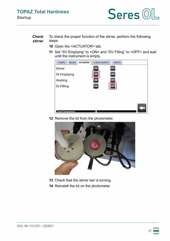
Checkstirrer
To check the proper function of the stirrer, perform the following steps:10 Open the <ACTUATOR> tab.11 Set “SV Emptying” to <ON> and “SV Filling” to <OFF> and wait
until the instrument is empty.
12 Remove the lid from the photometer.
13 Check that the stirrer bar is turning.14 Reinstall the lid on the photometer.
ON
ON
ON
ON
OFF
OFF
OFF
OFF
Stirrer
SV Emptying
Heating
SV Filling
ACTUATOR 4-20mA OUTPUTPUMPS RELAYS INPUTS
Vessel temperature :

SOL-96.110.051 / 250821
TOPAZ Total HardnessStartup
28
4.4. Run-in Period1 Go back to the main screen.2 Start measurement by pressing the button.3 Let the analyzer perform one or two measuring cycles before
proceeding with the next steps.
4.5. Manual Measurement1 Perform a manual measurement with a standard solution.
If the result of the manual measurement is satisfactory, no calibration is necessary.
2 Calibrate the analyzer if required.
For detailed descriptions, see Manual Measurement and Calibration, p. 39.
4.6. ProgrammingProgram the following parameters, if applicable: Concentration values for thresholds 1 and 2 Definition as “high/high”, “low/high” or “low/low” thresholds, Number of measuring cycles per channel Measuring interval If digital inputs are used or if the analyzer is to be controlled via
JBUS, select the appropriate control mode JBUS slave ID (set to a number higher than 16)
For detailed descriptions of all configuration options see Configuration of the Analyzer, p. 42.

SOL-96.110.051 / 250821
TOPAZ Total HardnessOperation
29
5. Operation
5.1. Access LevelsThere are two predefined access levels: User access: Allows viewing data in the main window. Access with extended permissions: Allows stopping the
measurement, changing settings and performing maintenance tasks.
The password for access with extended permissions is “0712”. After 10 minutes of inactivity, the password is requested again.
SOL-96.110.051 / 250821
TOPAZ Total HardnessOperation
30
5.2. User Interface
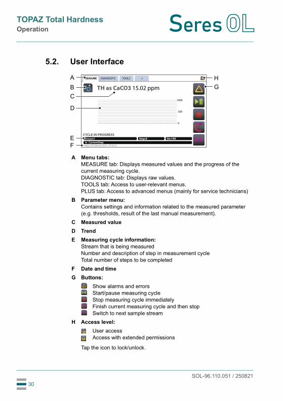
A Menu tabs:MEASURE tab: Displays measured values and the progress of the current measuring cycle.DIAGNOSTIC tab: Displays raw values.TOOLS tab: Access to user-relevant menus.PLUS tab: Access to advanced menus (mainly for service technicians)
B Parameter menu:Contains settings and information related to the measured parameter (e.g. thresholds, result of the last manual measurement).
C Measured valueD TrendE Measuring cycle information:
Stream that is being measuredNumber and description of step in measurement cycleTotal number of steps to be completed
F Date and timeG Buttons:
Show alarms and errorsStart/pause measuring cycleStop measuring cycle immediatelyFinish current measuring cycle and then stopSwitch to next sample stream
H Access level:User accessAccess with extended permissions
Tap the icon to lock/unlock.
TOOLS
TH as CaCO3 15.02 ppm
CYCLE IN PROGRESS
MEASURE DIAGNOSTIC +
Stream1 Step:0 On:190
m_CurrentStepFriday, 26 February 2021, 07:02:31
1000
500
0
GHA
BC
D
EF
SOL-96.110.051 / 250821
TOPAZ Total HardnessMaintenance
31
6. Maintenance
6.1. Maintenance Schedule
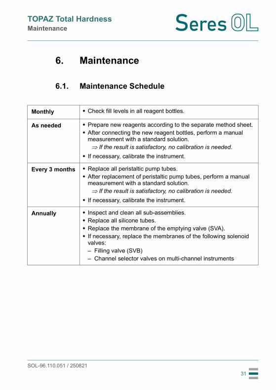
Monthly Check fill levels in all reagent bottles.
As needed Prepare new reagents according to the separate method sheet. After connecting the new reagent bottles, perform a manual
measurement with a standard solution. If the result is satisfactory, no calibration is needed.
If necessary, calibrate the instrument.
Every 3 months Replace all peristaltic pump tubes. After replacement of peristaltic pump tubes, perform a manual
measurement with a standard solution. If the result is satisfactory, no calibration is needed.
If necessary, calibrate the instrument.
Annually Inspect and clean all sub-assemblies. Replace all silicone tubes. Replace the membrane of the emptying valve (SVA). If necessary, replace the membranes of the following solenoid
valves:– Filling valve (SVB)– Channel selector valves on multi-channel instruments

SOL-96.110.051 / 250821
TOPAZ Total HardnessMaintenance
32
6.2. Stop of Operation for MaintenanceBefore performing any maintenance work on reagent or pump tubes, it is recommended to flush the reagent system with deionized water.
Note: • Before flushing the reagent tubes, make sure that the sample
inlet tap is open.• To avoid chemical reactions in the photometer, flush the
reagent tubes one after the other, not simultaneously.
Proceed as follows:1 Remove all reagent tubes from their bottles and place them in a
beaker filled with deionized water.2 Open the <PUMPS> tab.3 Press the <ON> button next to “P1 - HNB indicator”.
4 Let the pump run until it stops automatically. This takes approximately 2.5 minutes.
5 Repeat steps 3–4 with pumps “P2 - Buffer”, “P3 - EDTA N/50” and “P9 - H2SO4 2N”.
ON
ON
OFF
OFF
P1 - HNB indicator
P2 - Buffer
P3 - EDTA N/50
P9 - H2SO4 2N
ACTUATOR 4-20mA OUTPUTPUMPS RELAYS INPUTS
ON
ON
OFF
OFF

SOL-96.110.051 / 250821
TOPAZ Total HardnessMaintenance
33
6 Open the <ACTUATOR> tab and set “SV Filling” to <ON>.
7 Wait until the photometer has been filled with fresh water. Then set “SV Filling” to <OFF>.
ON
ON
ON
ON
OFF
OFF
OFF
OFF
Stirrer
SV Emptying
Heating
SV Filling
ACTUATOR 4-20mA OUTPUTPUMPS RELAYS INPUTS
Vessel temperature : 27.48 °C
SOL-96.110.051 / 250821
TOPAZ Total HardnessMaintenance
34
6.3. Replacing Reagents
WARNING
Multiple hazardsFor safe handling of the reagents, you must read and understand the Material Safety Data Sheets (MSDS). Wear appropriate protective equipment.
Note: • It is recommended to replace the reagents when there is
approximately 2–3 cm of reagent left in each bottle. Do not use up the reagents completely!
• Keep the old reagents until you are sure that the instrument measures correctly with the new reagents.
• Do not reuse the reagent bottles as this poses a risk of contamination or dilution errors.
Reagentconsumption
At the standard measurement interval, the following amounts of reagents are consumed: Hydroxynaphtol blue: 3 liters per month Buffer D2 pH 10: 4.5 liters per month H2SO4 2N: 3 liters per monthThe concentration of the EDTA reagent varies depending on the selected measuring range. The consumption is proportional to the measured total hardness and amounts to approximately 36 liters per month at the upper end of the measuring range.
Replacingreagents
1 Prepare the reagents according to the separate method sheet.2 Insert the reagent tubes all the way to the bottom of the corre-
sponding bottles (see Reagent tube numbering, p. 35).3 Check that there is an additional small hole in the lid of each
bottle that allows air to enter.
Final steps 4 Prime the reagent tubes (see Priming the Reagent Tubes, p. 25).5 Perform a manual measurement.
If the result is satisfactory, no calibration is needed.6 If necessary, calibrate the instrument (see Manual Measurement
and Calibration, p. 39).

SOL-96.110.051 / 250821
TOPAZ Total HardnessMaintenance
35
Reagent tubenumbering
No. Reagent type11 HNB PTFE 1.6×3.212 HNB PTFE 1.6×3.221 D2 buffer PTFE 1.6×3.222 D2 buffer PTFE 1.6×3.291 H2SO4 2N PTFE 1.6×3.292 H2SO4 2N PTFE 1.6×3.231 EDTA N/x PTFE 1.6×3.232 EDTA N/x PTFE 1.6×3.2
1
2
9
3
11 12
22
92
32
21
91
31
U1
V1
SVBNO
NC
SVANC
C
C
U1
V1
SVBNO
NC
SVANC
C
C
SOL-96.110.051 / 250821
TOPAZ Total HardnessMaintenance
36
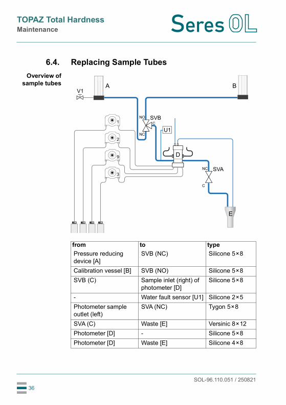
6.4. Replacing Sample TubesOverview of
sample tubes
from to typePressure reducing device [A]
SVB (NC) Silicone 5×8
Calibration vessel [B] SVB (NO) Silicone 5×8SVB (C) Sample inlet (right) of
photometer [D]Silicone 5×8
- Water fault sensor [U1] Silicone 2×5Photometer sample outlet (left)
SVA (NC) Tygon 5×8
SVA (C) Waste [E] Versinic 8×12Photometer [D] - Silicone 5×8Photometer [D] Waste [E] Silicone 4×8
A B
1
2
9
3
V1
SVBNO
NC
SVANC
C
C
D
E
U1

SOL-96.110.051 / 250821
TOPAZ Total HardnessMaintenance
37
6.5. Replacing Peristaltic Pump Tubes
WARNING
After rinsing with deionized water, reagent tubes may still contain traces of chemicalsWear appropriate protective equipment (gloves, glasses, protective clothing).
1 Flush the reagent tubes with deionized water as described in Stop of Operation for Maintenance, p. 32.
2 Turn the power switch to the OFF position.3 Loosen the three screws [A] on the front of the pump and remove
the front cover [B].
4 Remove the tube from the rotor [C] and disconnect it from both fittings [D].
A B
C DD D

SOL-96.110.051 / 250821
TOPAZ Total HardnessMaintenance
38
5 Connect the new tube to the right side fitting and roll the tube around the rotor while turning it.
6 Connect the other tube end to the left side fitting.
7 Install the front cover on the pump.8 Insert the reagent tubes all the way to the bottom of the
corresponding bottles (see Reagent tube numbering, p. 35).9 Prime the reagent tubes (see Priming the Reagent Tubes, p. 25).

SOL-96.110.051 / 250821
TOPAZ Total HardnessMaintenance
39
6.6. Manual Measurement and CalibrationMethods ofcalibration
The TOPAZ Total Hardness supports two methods of calibration: A standard calibration or an online calibration. Seres OL recommends to use the standard calibration. If you want to use the online calibration, contact customer service for details.
Entering themaintenance
menu
1 To stop the current measuring cycle, press the button on the main screen and enter the password “0712”. In the next dialog, confirm with “OK”.
2 From the main screen, open the <TOOLS> tab and press the <Maintenance> button.
The <MAINTENANCE> menu shows the following entries:
MEASURE DIAGNOSTIC +TOOLS
Maintenance Electrical testMaintenanceMaintenance Electrical test
MAINTENANCE DIAGNOSTIC
Stopped
Calibration
Calibration in line
Manual Measure

SOL-96.110.051 / 250821
TOPAZ Total HardnessMaintenance
40
6.6.1 Manual MeasurementThe <Manual measure> function can be used to verify the instrument performance using a standard solution. It is recommended to per-form one or two manual measurements before each calibration to obtain a meaningful result.1 Start the manual measurement by pressing the button.2 When the message "Add standard" appears, fill 2/3 of the
calibration vessel [A] with the standard.
3 Wait until the calibration vessel is empty and the message “Add standard” appears again.
4 Repeat steps 2 and 3 until the measurement starts automatically. 5 When the measurement is finished, add standard solution to the
calibration vessel again as requested on the screen.6 At the end of the manual measurement, a window displays
the result of the current and the previous (“Bf”) manual measure-ment. Confirm by pressing the button.
Note: The result of the latest manual measurement can later be viewed in the parameter menu.
A Calibration vessel
A
MANUAL MEASURE RESULTS
Manual Measure(Bf )
Manual Measure
20.02
19.87

SOL-96.110.051 / 250821
TOPAZ Total HardnessMaintenance
41
6.6.2 Standard CalibrationNote: • On multi-channel instruments, only calibrate sample stream 1.
Procedure The procedure is similar to the manual measurement procedure described in Manual Measurement, p. 40.Begin calibration by entering the reference value of the standard used. Pay attention to the correct concentration unit (ppm by de-fault). Then follow the instructions on the screen.
Resultsscreen
At the end of the standard calibration, a window displays the previ-ous (actual) and the new (calculated) calibration coefficient and the concentration measurement readings before and after calibration. Confirm by pressing the button.
6.7. Longer Stop of OperationIf the instrument is going to be switched off for a few days or longer, proceed as follows:
1 Prime the reagent system with deionized water as described in Stop of Operation for Maintenance, p. 32.
2 Clean the photometer thoroughly with diluted hydrochloric acid.Note: Do not use a bottle brush, as this could scratch the optics.
3 Remove algae and particles present in sample tubes.4 Fill the sample tubes and the photometer with deionized water.
CALIBRATION RESULTS
Actual coefficient
Coef. Calculated
Measure before calib
Measure after calib
1.040
1.047
20.15
20.00

SOL-96.110.051 / 250821
TOPAZ Total HardnessConfiguration of the Analyzer
42
7. Configuration of the Analyzer
Options MenuTo access the options menu, open the <TOOLS> tab from the main screen and press the <Options> button. Enter password “0712” if necessary.
OPTIONS tabSleep mode
(min)Set the time after which the display automatically turns off (tapping turns it back on). If 0 seconds are set, the display will never turn off.
temp. setpoint Setpoint of the regulated temperature in photometer.Adjust this value only if instructed to do so by Seres OL customer service.
pressuresetting
Setpoint of the water fault sensor.Adjust this value only if instructed to do so by Seres OL customer service.
Gain setpoint Setpoint of the electronic gain.Adjust this value only if instructed to do so by Seres OL customer service.
JBUS slave ID Set the JBUS slave ID to a number higher than 16.
Control mode Select the appropriate control mode.Status of relays, analog signal outputs and digital inputs in each mode:
Setting Relays 4/20 mA Digital inputs Jbus0 - Local Activated Activated Frozen
(stop/start on keyboard)
Reading
1 - Maintenance Activated Frozen Frozen Reading2 - Jbus Activated Activated Frozen Reading,
Writing3 - Remote control Activated Activated Activated Reading

SOL-96.110.051 / 250821
TOPAZ Total HardnessConfiguration of the Analyzer
43
AUTO CYCLE tabThe AUTO CYCLE tab contains settings for performing automatic calibration cycles. This requires the installation of additional compo-nents.Contact Seres OL customer service for details.
SCHEDULER tabThe SCHEDULER tab allows to configure the number measuring cycles per channel (multichannel configurations) or to extend the standard measurement interval by adding a pause between mea-surement cycles.
Note: Since the analyzer is designed for continuous operation, a maximum duration of 15 minutes is recommended for pauses.
1 Press the “Add” button and select one of the following options: Pause Stream 1 Streams 2, 3, 4, 5, or 6 (if applicable) An entry field for the number of cycles or pause duration
appears to the right of the newly added entry.2 Tap on the entry field and set the required number of cycles or
pause duration.3 To remove an entry, press the button next to it.
Stream 1 1Cycle
Pause 5Minutes
Stream 2 1Cycle
Pause 5 Minutes
Add
Add
Add
Add
Add
Add
Add
Add
AUTO. CYCLES THRESHOLD DATE/TIMEOPTIONS SCHEDULER
1 :2 :3 :4 :5 :6 :7 :8 :9 :
10 :11 :12 :

SOL-96.110.051 / 250821
TOPAZ Total HardnessConfiguration of the Analyzer
44
THRESHOLD tabThe THRESHOLD tab allows to define whether the thresholds for relays OUT_DIG3 and OUT_DIG4 are high or low thresholds. The combinations high/high, low/high and low/low are possible.
The threshold values can be set in the parameter menu, see 45.
DATE/TIME tabSet time and date.
AB
Setting for threshold 1 / relay OUT_DIG3Setting for threshold 2 / relay OUT_DIG4
Low/HighStream 1 measure 1
OPTIONS SCHEDULER DATE/TIMEAUTO. CYCLES THRESHOLD
A B

SOL-96.110.051 / 250821
TOPAZ Total HardnessConfiguration of the Analyzer
45
Parameter MenuTo access the parameter menu, press the button on the main screen. The parameter menu allows user to make the following settings:
Threshold 1 Threshold value for relay OUT_DIG3.The definition as high or low threshold value is made in the <THRESHOLD> tab of the <OPTIONS> menu.
Threshold 2 Threshold value for relay OUT_DIG4.The definition as high or low threshold value is made in the <THRESHOLD> tab of the <OPTIONS> menu.
Min. 4–20mA Beginning point of the linear scale.
Max. 4–20mA End point of the linear scale.
Note: In addition to the settings listed above, the Parameter menu contains further settings which are not documented in this manual. Adjust these values only if instructed to do so by Seres OL customer service.

SOL-96.110.051 / 250821
TOPAZ Total HardnessTroubleshooting
46
8. Troubleshooting
This chapter provides some hints to make troubleshooting easier. For detailed information on how to replace or clean parts refer to Maintenance, p. 31.If you need help please contact your local distributor. Please have the serial number and the diagnostic values (see 58) ready.
8.1. What To Do If...
Instrument is not starting
Application is not launching
Instrument shows error message “Water default” although there is sample flow
Possible cause Corrective actionNo power on the socket – Check mains power supply.Power supply defective – Check output voltage of the
internal 24-volt power supply.Panel PC not powered – Check connections at the back
of the panel PC.
Possible cause Corrective actionThe instrument starts, but the panel PC does not.
– Check connections at the back of the panel PC.
Possible cause Corrective actionFiling solenoid valve (SVB) does not switch
– Check that the solenoid valve is plugged in correctly.
One or more sample tubes are blocked or pinched.
– Check condition of all sample tubes (inside and outside).

SOL-96.110.051 / 250821
TOPAZ Total HardnessTroubleshooting
47
Vessel is not emptied and/or the vessel is overflowing through vent tube
Photometer does not fill
Measured value is not updated
Screen does not work
Possible cause Corrective actionTubes are blocked – Check condition of emptying
tubes (inside and outside).Emptying tube is pinched – Make sure that the emptying
tube is not pinched when closing the door.
Emptying solenoid valve (SVA) does not switch
– Check that the solenoid valve is plugged in correctly.
– If necessary, change the membrane.
Possible cause Corrective actionPump does not work properly
– Check that pump is connected correctly and that it is not blocked.
One or more tubes are blocked or pinched
– Check condition of all sample tubes.
Possible cause Corrective actionThe same value was measured twice
– No action necessary.
Measurement was stopped or paused
– Start measurement again.
Possible cause Corrective actionThe application does not react.
– Restart the analyzer.
Screen is damaged. – Contact customer support.
SOL-96.110.051 / 250821
TOPAZ Total HardnessTroubleshooting
48
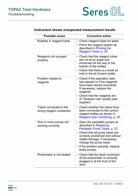
Instrument shows unexpected measurement results
Possible cause Corrective actionBubbles in reagent tubes – Check reagent tubes for leaks.
– Prime the reagent system as described in Priming the Reagent Tubes, p. 25.
Reagents not pumped properly
– Check that the reagent tubes are cut at an angle and immersed all the way to the bottom of the bottles.
– Check that there is a small air inlet in the lid of each bottle.
Problem related to reagents
– Check if the expiration date has passed or if the reagents have been stored incorrectly. If necessary, replace the reagents.
– Check that the reagents are of "Analysis Use" quality (ask supplier).
Tubes connected to the wrong reagent containers
– Check whether the tubes have been connected to the correct reagent bottles as shown in Reagent tube numbering, p. 35.
One or more pumps not working correctly
– Open the peristaltic pumps as described in Replacing Peristaltic Pump Tubes, p. 37.
– Check that all pump tubes are correctly positioned and without visible damage. If necessary, change the pump tubes.
– If the problem persists, replace faulty pumps.
Photometer is not heated – Check that the black connector of the photometer is correctly plugged in at the front of the door.

SOL-96.110.051 / 250821
TOPAZ Total HardnessTroubleshooting
49
Stirrer does not rotate or is missing
– Remove the photometer lid and check that a magnetic stirrer bar is installed.
– Activate the stirrer in the <ACTUATOR> tab of the <Electrical Test> menu. The magnetic stirrer bar should be rotating continuously.
– Check that the black connector of the photometer is correctly plugged in at the front of the door.
– If the error persists, contact customer service.
Sample is turbid or contains bubbles
– Check that the upstream filter system is working correctly (if present).
– If no filter system is installed, it might be necessary to install one.
Water does not drain – Check that the drain is pressure-free and not blocked.
– Check condition of emptying tube (inside and outside).
– Make sure that no tubes are pinched when closing the door.
Analyzer is poorly calibrated
– Check if the expiration date of the standard solution has passed or if it has been stored incorrectly. If necessary, replace the standard solution.
– Recalibrate the analyzer.Interference in the sample – Contact customer service.Condensation in the double cover of the photometer and/or the desiccant tablet is saturated with water
– Check desiccant tablets.– Check seal integrity.
Possible cause Corrective action

SOL-96.110.051 / 250821
TOPAZ Total HardnessTroubleshooting
50
8.2. List of Errors and Alarms
No. Text shown on display Corrective action1 Unknown parameter or variable – Contact customer support.
2 Error reading cycle configuration – Reset analyzer configuration to factory defaults by pressing the <Recover> button in the <+> tab.
3 Error writing cycle configuration – Reset analyzer configuration to factory defaults by pressing the <Recover> button in the <+> tab.
4 Error cycle execution – Observe the “Live optical measure” value in the <DIAGNOSTIC> tab. With a functioning measuring card, the value changes continuously.
– If the value does not change, restart the analyzer and check again.
– If the error persists, contact customer support.
5 Error reading cycle zero configuration
– Reset analyzer configuration to factory defaults by pressing the <Recover> button in the <+> tab.
6 Error writing cycle zero configuration
– Reset analyzer configuration to factory defaults by pressing the <Recover> button in the <+> tab.
7 Error cycle zero execution – Observe the “Live optical measure” value in the <DIAGNOSTIC> tab. With a functioning measuring card, the value changes continuously.
– If the value does not change, restart the analyzer and check again.
– If the error persists, contact customer support.
8 Error reading calibration cycle configuration
– Reset analyzer configuration to factory defaults by pressing the <Recover> button in the <+> tab.
9 Error writing calibration cycle configuration
– Reset analyzer configuration to factory defaults by pressing the <Recover> button in the <+> tab.
SOL-96.110.051 / 250821
TOPAZ Total HardnessTroubleshooting
51
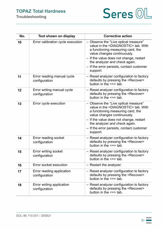
10 Error calibration cycle execution – Observe the “Live optical measure” value in the <DIAGNOSTIC> tab. With a functioning measuring card, the value changes continuously.
– If the value does not change, restart the analyzer and check again.
– If the error persists, contact customer support.
11 Error reading manual cycle configuration
– Reset analyzer configuration to factory defaults by pressing the <Recover> button in the <+> tab.
12 Error writing manual cycle configuration
– Reset analyzer configuration to factory defaults by pressing the <Recover> button in the <+> tab.
13 Error cycle execution – Observe the “Live optical measure” value in the <DIAGNOSTIC> tab. With a functioning measuring card, the value changes continuously.
– If the value does not change, restart the analyzer and check again.
– If the error persists, contact customer support.
14 Error reading socket configuration
– Reset analyzer configuration to factory defaults by pressing the <Recover> button in the <+> tab.
15 Error writing socket configuration
– Reset analyzer configuration to factory defaults by pressing the <Recover> button in the <+> tab.
16 Error socket execution – Restart the analyzer.
17 Error reading application configuration
– Reset analyzer configuration to factory defaults by pressing the <Recover> button in the <+> tab.
18 Error writing application configuration
– Reset analyzer configuration to factory defaults by pressing the <Recover> button in the <+> tab.
No. Text shown on display Corrective action
SOL-96.110.051 / 250821
TOPAZ Total HardnessTroubleshooting
52
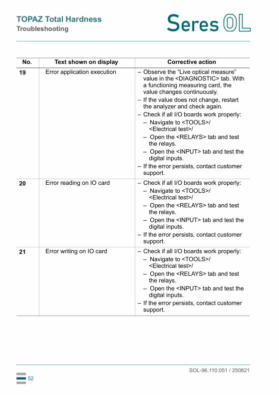
19 Error application execution – Observe the “Live optical measure” value in the <DIAGNOSTIC> tab. With a functioning measuring card, the value changes continuously.
– If the value does not change, restart the analyzer and check again.
– Check if all I/O boards work properly:– Navigate to <TOOLS>/
<Electrical test>/– Open the <RELAYS> tab and test
the relays.– Open the <INPUT> tab and test the
digital inputs.– If the error persists, contact customer
support.
20 Error reading on IO card – Check if all I/O boards work properly:– Navigate to <TOOLS>/
<Electrical test>/– Open the <RELAYS> tab and test
the relays.– Open the <INPUT> tab and test the
digital inputs.– If the error persists, contact customer
support.
21 Error writing on IO card – Check if all I/O boards work properly:– Navigate to <TOOLS>/
<Electrical test>/– Open the <RELAYS> tab and test
the relays.– Open the <INPUT> tab and test the
digital inputs.– If the error persists, contact customer
support.
No. Text shown on display Corrective action
SOL-96.110.051 / 250821
TOPAZ Total HardnessTroubleshooting
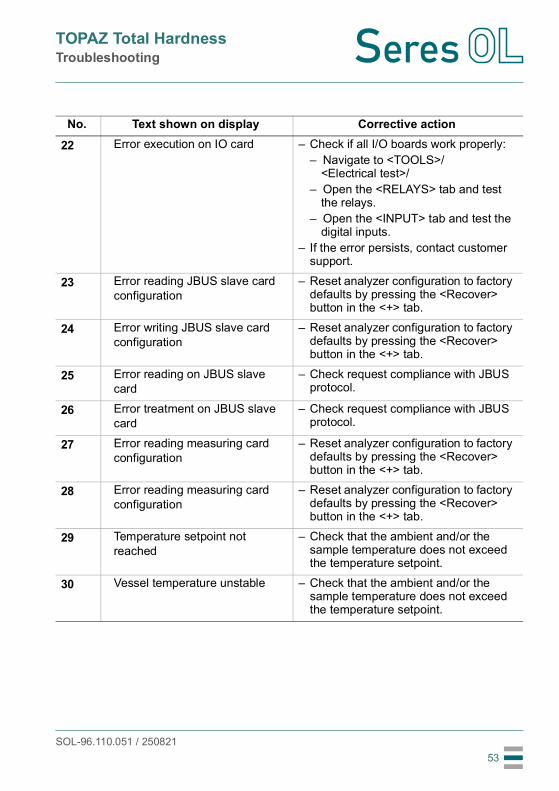
53
22 Error execution on IO card – Check if all I/O boards work properly:– Navigate to <TOOLS>/
<Electrical test>/– Open the <RELAYS> tab and test
the relays.– Open the <INPUT> tab and test the
digital inputs.– If the error persists, contact customer
support.
23 Error reading JBUS slave card configuration
– Reset analyzer configuration to factory defaults by pressing the <Recover> button in the <+> tab.
24 Error writing JBUS slave card configuration
– Reset analyzer configuration to factory defaults by pressing the <Recover> button in the <+> tab.
25 Error reading on JBUS slave card
– Check request compliance with JBUS protocol.
26 Error treatment on JBUS slave card
– Check request compliance with JBUS protocol.
27 Error reading measuring card configuration
– Reset analyzer configuration to factory defaults by pressing the <Recover> button in the <+> tab.
28 Error reading measuring card configuration
– Reset analyzer configuration to factory defaults by pressing the <Recover> button in the <+> tab.
29 Temperature setpoint not reached
– Check that the ambient and/or the sample temperature does not exceed the temperature setpoint.
30 Vessel temperature unstable – Check that the ambient and/or the sample temperature does not exceed the temperature setpoint.
No. Text shown on display Corrective action

SOL-96.110.051 / 250821
TOPAZ Total HardnessTroubleshooting
54
31 Water default – Check that the analyzer is supplied with water.
– Check if the filling valve (SVB) switches. If this is not the case, perform the following steps:– Check that the cable is correctly
plugged in at the back of the solenoid valve.
– If necessary, replace the membrane.– Check sample tubes.
32 Pressure measure default - Measure < 0
– Check that the analyzer is supplied with water.
– Check if the filling valve (SVB) switches. If this is not the case, perform the following steps:– Check that the cable is correctly
plugged in at the back of the solenoid valve.
– If necessary, replace the membrane.– Check sample tubes.
33 Optical setting Default - Info setting not received
– Observe the “Live optical measure” value in the <DIAGNOSTIC> tab. With a functioning measuring card, the value changes continuously.
– If the value does not change, restart the analyzer and check again.
– If the value changes, launch a new cycle and check if the error is still displayed.
– If the error persists, contact customer support.
34 Measure default - measure < 0 (optical measure higher than baseline measured at beginning of measuring cycle).
– Check if the reagents have been stored incorrectly.
– Check that reagents are correctly pumped into the photometer.
– Check that the stirrer turns.
35 Measure stability default – Check that the optical fibers are well connected to their holder on the door.
No. Text shown on display Corrective action

SOL-96.110.051 / 250821
TOPAZ Total HardnessTroubleshooting
55
36 Division by zero - Measure = 0 – Check that the optical fibers are well connected to their holder on the door.
38 Concentration = 0 - calibration coeff. = 0
– Check that the calibration coefficient is not equal to zero.
– Make a new calibration.
39 Concentration out of range – Perform a manual measurement to check if the analyzer is correctly calibrated.
40 Division by zero - Concentration after linearization = 0 or Calibra-tion Coeff. = 0
– Check if the calibration coefficient is equal to zero. In this case, make a new calibration.
– Check if the final absorbance is equal to zero. If this is the case, the reaction has not occurred. Perform the following steps:– Check that the reagents are well
injected into the photometer.– Check that the stirrer turns.
41 Calibration coefficient outside tolerances (new coefficient differs from the previous one by more than 50 %)
– Check that standard concentration entered at the beginning of calibration matches the real standard concentration.
– Check that the standard solution been prepared and stored correctly.
– Check that reagents are correctly pumped into the photometer.
– Check that the stirrer turns.
42 Division by zero - Absorbance = 0 or Current Calibration Coeff. = 0
– Check if the calibration coefficient is equal to zero. In this case, perform a new calibration.
– Check if the final absorbance is equal to zero. If this is the case, the reaction has not occurred.Perform the following steps:– Check that the reagents are well
injected into the photometer.– Check that the stirrer turns.
No. Text shown on display Corrective action

SOL-96.110.051 / 250821
TOPAZ Total HardnessTroubleshooting
56
43 Division by zero - Absorbance = -999998.0
– Check that the optical fibers are well connected to their holder on the door.
44 Value out of range – Check that the analyzer is well calibrated, check standard solution concentration by a manual measure cycle.
45 Division by zero - Absorbance = -999998.0
– Check that the optical fibers are well connected to their holder on the door.
46 Incorrect projector power – Contact customer service
47 Threshold 1 exceeded – Check process– Check programmed value for
threshold 1
48 Threshold 2 exceeded – Check process– Check programmed value for
threshold 2
49 Optical setting incorrect (analyzer cannot adjust the optical gain)
– Check that the optical fibers are well connected to their holder on the door.
– Check that the photometer is not dirty.– Check that the analyzer is supplied
with water.– Check that the stirrer turns.
No. Text shown on display Corrective action

SOL-96.110.051 / 250821
TOPAZ Total HardnessTroubleshooting
57
50 Optical setting incorrect - G=0(analyzer cannot adjust the optical gain)
– Check that the optical fibers are well connected to their holder on the door.
– Check that the photometer is not dirty.– Check that the analyzer is supplied
with water.– Check that the stirrer turns.
51 Optical setting incorrect - G=255(analyzer cannot adjust the optical gain)
– Check that the optical fibers are well connected to their holder on the door.
– Check that the photometer is not dirty.– Check that the analyzer is supplied
with water.– Check that the stirrer turns.
54 [Sample&Add1] < [Add1] – Check liquid level in the vessel.– If OK, check reagents validity and
reagents are injected when stirrer is active.
55 Threshold delta < setpoint – Check liquid level in the vessel.– If OK, check reagents validity and
reagents are injected when stirrer is active.
No. Text shown on display Corrective action
SOL-96.110.051 / 250821
TOPAZ Total HardnessTroubleshooting
58
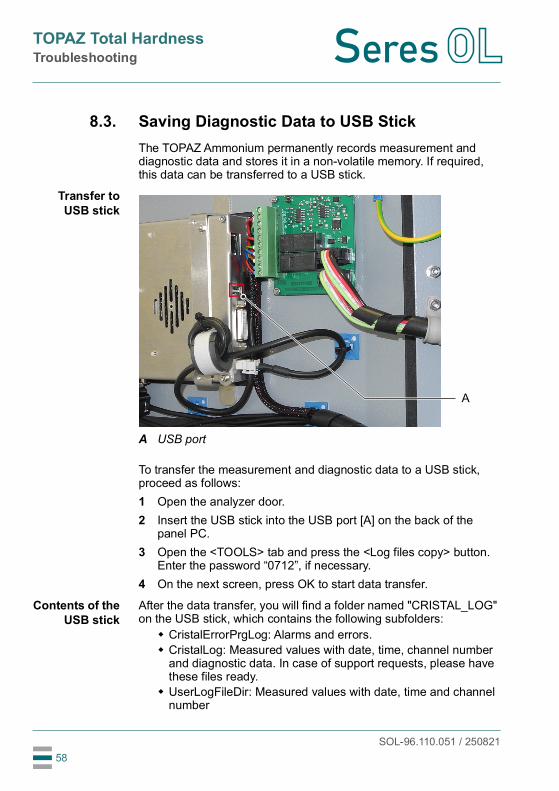
8.3. Saving Diagnostic Data to USB StickThe TOPAZ Ammonium permanently records measurement and diagnostic data and stores it in a non-volatile memory. If required, this data can be transferred to a USB stick.
Transfer toUSB stick
To transfer the measurement and diagnostic data to a USB stick, proceed as follows:1 Open the analyzer door.2 Insert the USB stick into the USB port [A] on the back of the
panel PC.3 Open the <TOOLS> tab and press the <Log files copy> button.
Enter the password “0712”, if necessary.4 On the next screen, press OK to start data transfer.
Contents of theUSB stick
After the data transfer, you will find a folder named "CRISTAL_LOG" on the USB stick, which contains the following subfolders: CristalErrorPrgLog: Alarms and errors. CristalLog: Measured values with date, time, channel number
and diagnostic data. In case of support requests, please have these files ready.
UserLogFileDir: Measured values with date, time and channel number
A USB port
A
TOPAZ Total HardnessNotes
SOL-96.110.051 / 25082159
9. Notes

TOPAZ Total Hardness
SOL-96.110.051 / 250821
Sur
face
Wat
er
Potable Water
Process Water
Waste Water & Ef uents
Oil &
Gas
Seres OL SAS ∙ FR-13730 Saint-Victoretwww.seres-ol.com ∙ [email protected]
Seres OL Products - Analytical Instruments for:
Seres OL is represented worldwide by subsidiary companies and distributors and cooperates with independent representatives all over the world. For contact information, please scan the QR code.