Embed Size (px)
Citation preview
Software Integrated Solutions
Sch
lum
be
rger P
ub
lic
Interpreting
ProSource Seabed Diagrams

Copyright Notice Copyright © 2016 Schlumberger. All rights reserved.
No part of this document may be reproduced, stored in an information retrieval system, or translated or retransmitted in any form or by any means, electronic or mechanical, including photocopying and recording, without the prior written permission of the copyright owner.
Trademarks Schlumberger trademarks that may appear in this document include, but are not limited to ProSource and Seabed.
All other company or product names mentioned are used for identification purposes only and may be trademarks of their respective owners.
Table of Contents
Interpreting ProSource Seabed Diagrams ...................................................................................... 1
1.1 Document Purpose ....................................................................................................... 1
1.2 What is a Seabed Diagram? .......................................................................................... 1
Example Diagram ............................................................................................................................ 2
1.3 Seabed Diagramming Notation ..................................................................................... 3
1.4 Abstract Class ................................................................................................................ 6
1.5 Concrete Class ............................................................................................................... 6
1.6 Attribute ........................................................................................................................ 7
1.7 Attribute Value Domain ................................................................................................ 7
1.8 Association .................................................................................................................... 8
1.9 Association Multiplicity ................................................................................................. 9
1.10 Association Delete Semantic ...................................................................................... 11
1.11 Composition Association ............................................................................................ 13
1.12 Generalization ............................................................................................................. 14
Appendix A – Association Implementation Techniques Mentioned in the Web Report ............. 15
Appendix B – Associations Referencing Abstract Classes ............................................................. 16
Example B-1 .................................................................................................................................. 17
B.1 Single Abstract ............................................................................................................ 18
B.1.1 Physical Implementation ............................................................................................ 18
B.1.1.1 Referential Integrity .................................................................................................... 18
B.1.1.2 Multiplicity .................................................................................................................. 18
B.1.1.3 Web Report Representation ....................................................................................... 18
B.1.1.4 Data Example .............................................................................................................. 19
B.1.2 Assoc ........................................................................................................................... 19
B.1.1.5 Physical Implementation ............................................................................................ 19
B.1.1.6 Referential Integrity .................................................................................................... 20
B.1.1.7 Multiplicity .................................................................................................................. 21
B.1.1.8 Web Report Representation ....................................................................................... 21
B.1.1.9 Data Example .............................................................................................................. 21
Interpreting ProSource Seabed Diagrams
1
Copyright © 2016 Schlumberger. All rights reserved.
Interpreting ProSource Seabed Diagrams
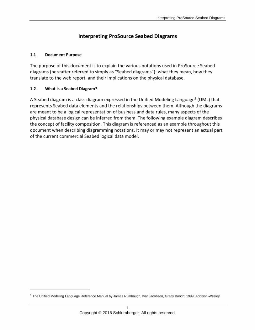
1.1 Document Purpose
The purpose of this document is to explain the various notations used in ProSource Seabed diagrams (hereafter referred to simply as “Seabed diagrams”): what they mean, how they translate to the web report, and their implications on the physical database.
1.2 What is a Seabed Diagram?
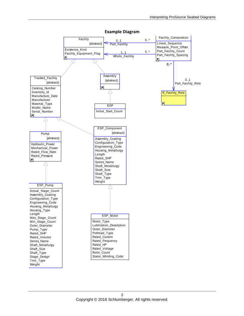
A Seabed diagram is a class diagram expressed in the Unified Modeling Language1 (UML) that represents Seabed data elements and the relationships between them. Although the diagrams are meant to be a logical representation of business and data rules, many aspects of the physical database design can be inferred from them. The following example diagram describes the concept of facility composition. This diagram is referenced as an example throughout this document when describing diagramming notations. It may or may not represent an actual part of the current commercial Seabed logical data model.
1 The Unified Modeling Language Reference Manual by James Rumbaugh, Ivar Jacobson, Grady Booch; 1999; Addison-Wesley
Interpreting ProSource Seabed Diagrams
2
Copyright © 2016 Schlumberger. All rights reserved.
Example Diagram
0..*0..1Part_Facility
0..*1..1Whole_Facility
0..*
0..1Part_Facility_Role
ESP
Initial_Start_Count
ESP_Component
{abstract}
Assembly_Coating
Configuration_Type
Engineering_Code
Housing_Metallurgy
Length
Rated_SHP
Series_Name
Shaft_Metallurgy
Shaft_Size
Shaft_Type
Trim_Type
WeightESP_Pump
Actual_Stage_Count
Assembly_Coating
Configuration_Type
Engineering_Code
Housing_Metallurgy
Housing_TypeLength
Max_Stage_Count
Min_Stage_Count
Outer_Diameter
Pump_Type
Rated_SHP
Rated_Volume
Series_Name
Shaft_Metallurgy
Shaft_Size
Shaft_Type
Stage_Design
Trim_Type
Weight
ESP_Motor
Motor_Type
Lubrication_Description
Outer_Diameter
Pothead_Type
Rated_Current
Rated_Frequency
Rated_HP
Rated_Voltage
Rotor_Count
Stator_Winding_Code
Facility
{abstract}
Existence_Kind
Facility_Equipment_Flag
Facility_Composition
Linear_Sequence
Measure_Point_Offset
Part_Facility_Count
Part_Facility_Spacing
R_Facility_Role
Assembly
{abstract} Tracked_Facility
{abstract}
Catalog_Number
Inventory_Id
Manufacture_Date
Manufacturer
Material_Type
Model_Name
Serial_Number
Pump
{abstract}
Hydraulic_Power
Mechanical_Power
Rated_Flow_Rate
Rated_Pressure
0..*
Interpreting ProSource Seabed Diagrams
3
Copyright © 2016 Schlumberger. All rights reserved.
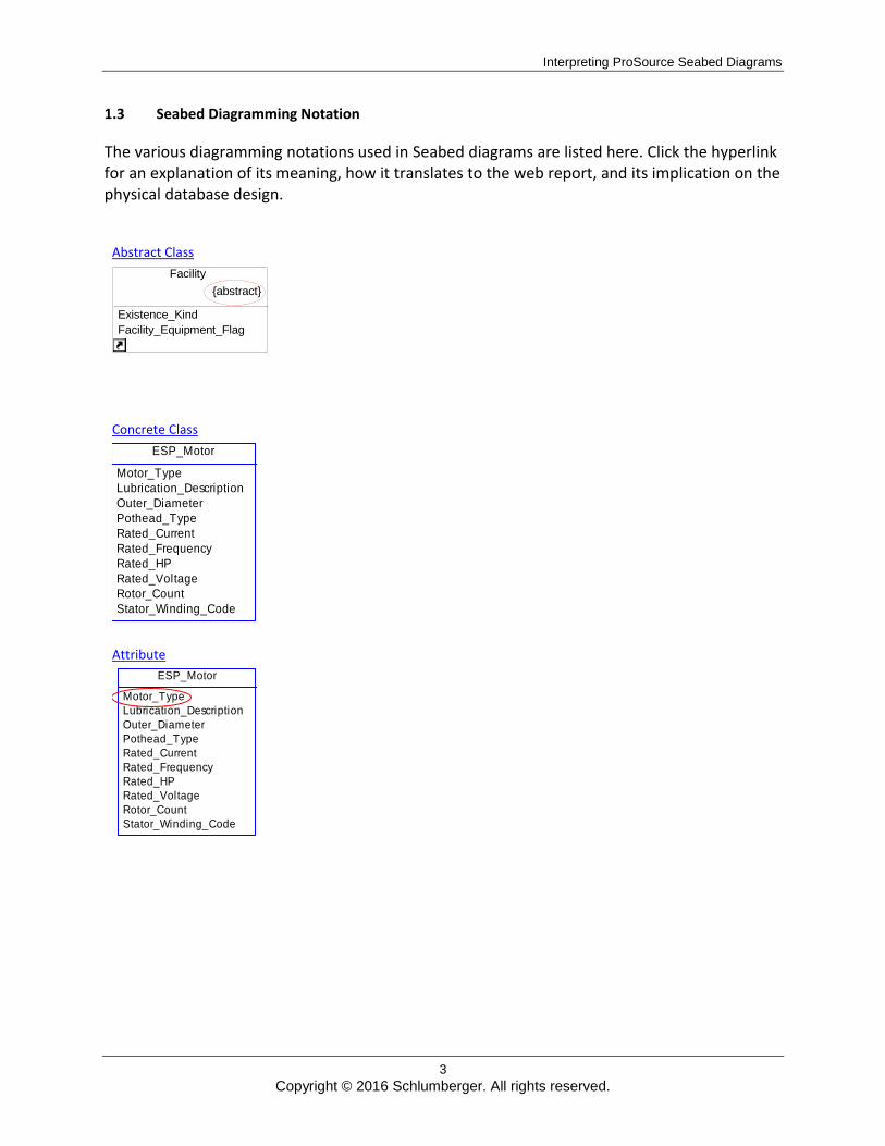
1.3 Seabed Diagramming Notation
The various diagramming notations used in Seabed diagrams are listed here. Click the hyperlink for an explanation of its meaning, how it translates to the web report, and its implication on the physical database design.
Abstract Class
Facility {abstract}
Existence_Kind Facility_Equipment_Flag
Concrete Class
Attribute
ESP_Motor
Motor_Type
Lubrication_Description
Outer_Diameter
Pothead_Type
Rated_Current
Rated_Frequency
Rated_HP
Rated_Voltage
Rotor_Count
Stator_Winding_Code
ESP_Motor
Motor_Type
Lubrication_Description
Outer_Diameter
Pothead_Type
Rated_Current
Rated_Frequency
Rated_HP
Rated_Voltage
Rotor_Count
Stator_Winding_Code
Interpreting ProSource Seabed Diagrams
4
Copyright © 2016 Schlumberger. All rights reserved.
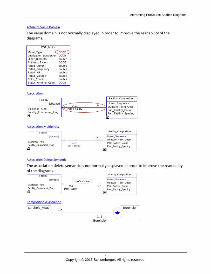
Attribute Value Domain
The value domain is not normally displayed in order to improve the readability of the diagrams.
Association
Association Multiplicity
0..* 0..1
Part_Facility
Facility {abstract}
Existence_Kind Facility_Equipment_Flag
Facility_Composition
Linear_Sequence Measure_Point_Offset Part_Facility_Count Part_Facility_Spacing
Association Delete Semantic
The association delete semantic is not normally displayed in order to improve the readability of the diagrams.
<<Cascade>> 0..* 0..1
Part_Facility
Facility {abstract}
Existence_Kind Facility_Equipment_Flag
Facility_Composition
Linear_Sequence Measure_Point_Offset Part_Facility_Count Part_Facility_Spacing
Composition Association
0..*
1..1 Borehole
Borehole Borehole_Alias
ESP_Motor
Motor_Type
Lubrication_Description
Outer_Diameter
Pothead_Type
Rated_Current
Rated_Frequency
Rated_HP
Rated_Voltage
Rotor_Count
Stator_Winding_Code
CODE
CODE
double
CODE
double
double
double
double
double
CODE
0..*0..1Part_Facility
Facility
{abstract}
Existence_Kind
Facility_Equipment_Flag
Facility_Composition
Linear_Sequence
Measure_Point_Offset
Part_Facility_Count
Part_Facility_Spacing
Interpreting ProSource Seabed Diagrams
5
Copyright © 2016 Schlumberger. All rights reserved.
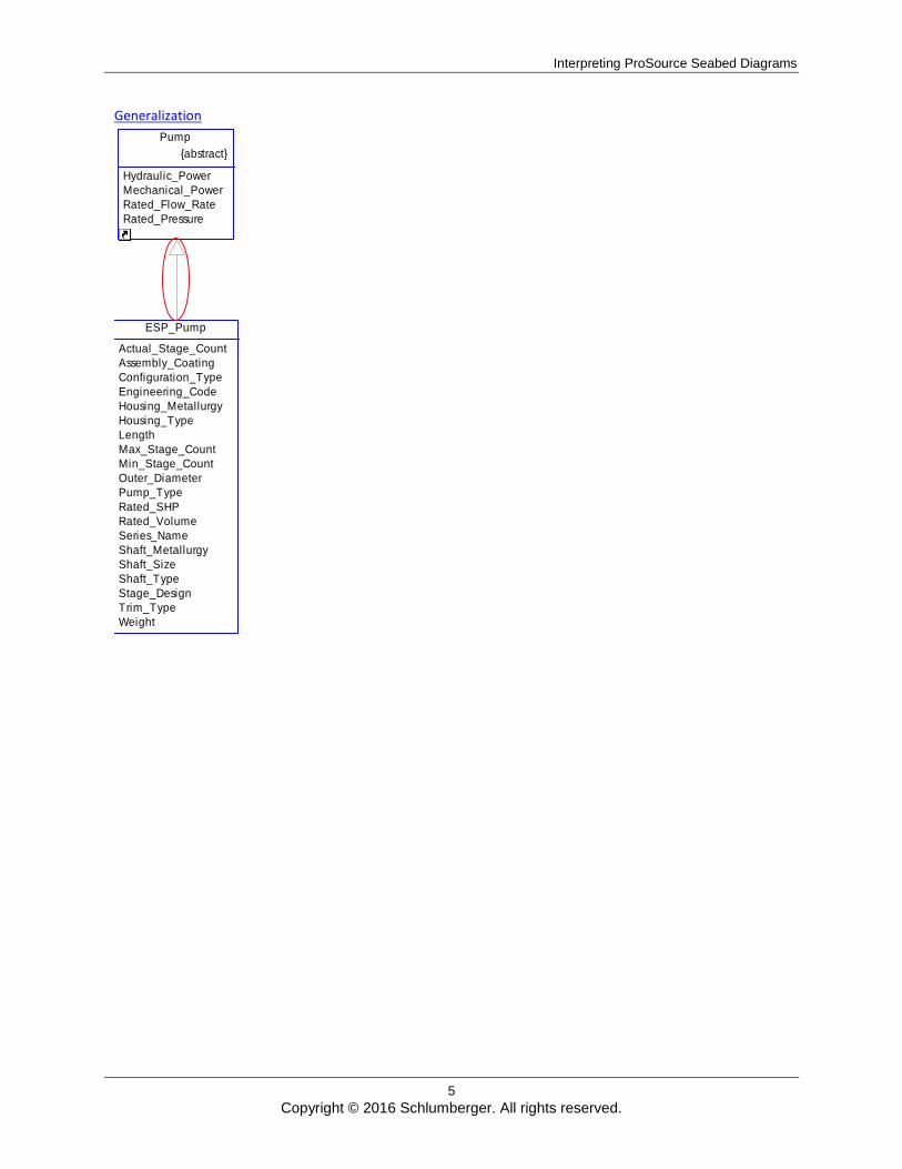
Generalization
ESP_Pump
Actual_Stage_Count
Assembly_Coating
Configuration_Type
Engineering_Code
Housing_Metallurgy
Housing_Type
Length
Max_Stage_Count
Min_Stage_Count
Outer_Diameter
Pump_Type
Rated_SHP
Rated_Volume
Series_Name
Shaft_Metallurgy
Shaft_Size
Shaft_Type
Stage_Design
Trim_Type
Weight
Pump
{abstract}
Hydraulic_Power
Mechanical_Power
Rated_Flow_Rate
Rated_Pressure
Interpreting ProSource Seabed Diagrams
6
Copyright © 2016 Schlumberger. All rights reserved.
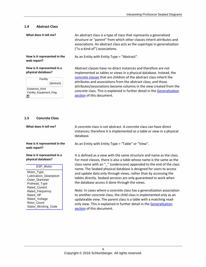
1.4 Abstract Class
What does it tell me? An abstract class is a type of class that represents a generalized structure or “parent” from which other classes inherit attributes and associations. An abstract class acts as the supertype in generalization (“is-a-kind-of”) associations.
How is it represented in the web report?
As an Entity with Entity Type = “Abstract”.
How is it represented in a physical database?
Facility
{abstract}
Existence_Kind Facility_Equipment_Flag
Abstract classes have no direct instances and therefore are not implemented as tables or views in a physical database. Instead, the concrete classes that are children of the abstract class inherit the attributes and associations from the abstract class; and those attributes/associations become columns in the view created from the concrete class. This is explained in further detail in the Generalization section of this document.
1.5 Concrete Class
What does it tell me? A concrete class is not abstract. A concrete class can have direct instances; therefore it is implemented as a table or view in a physical database.
How is it represented in the web report?
As an Entity with Entity Type = “Table” or “View”.
How is it represented in a physical database?
It is defined as a view with the same structure and name as the class. For most classes, there is also a table whose name is the same as the class name with an “_” (underscore) appended to the end of the class name. The Seabed physical database is designed for users to access and update data only through views, rather than by accessing the tables directly. Seabed services are only guaranteed to work when the database access it done through the views.
Note: In cases where a concrete class has a generalization association to another concrete class, the child class is implemented only as an updateable view. The parent class is a table with a matching read-only view. This is explained in further detail in the Generalization section of this document.
ESP_Motor
Motor_Type
Lubrication_Description
Outer_Diameter
Pothead_Type
Rated_Current
Rated_Frequency
Rated_HP
Rated_Voltage
Rotor_Count
Stator_Winding_Code
Interpreting ProSource Seabed Diagrams
7
Copyright © 2016 Schlumberger. All rights reserved.
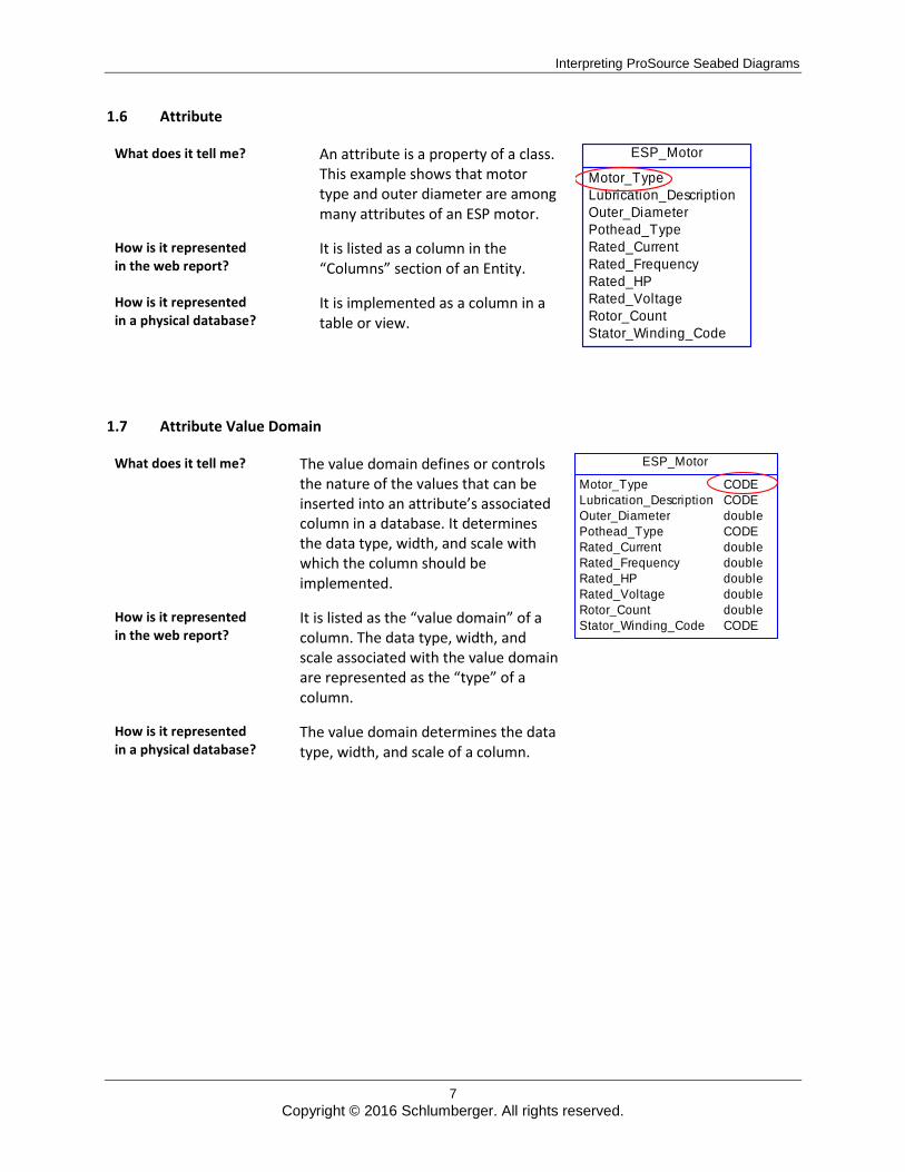
1.6 Attribute
What does it tell me? An attribute is a property of a class. This example shows that motor type and outer diameter are among many attributes of an ESP motor.
How is it represented in the web report?
It is listed as a column in the “Columns” section of an Entity.
How is it represented in a physical database?
It is implemented as a column in a table or view.
1.7 Attribute Value Domain
What does it tell me? The value domain defines or controls the nature of the values that can be inserted into an attribute’s associated column in a database. It determines the data type, width, and scale with which the column should be implemented.
How is it represented in the web report?
It is listed as the “value domain” of a column. The data type, width, and scale associated with the value domain are represented as the “type” of a column.
How is it represented in a physical database?
The value domain determines the data type, width, and scale of a column.
ESP_Motor
Motor_Type
Lubrication_Description
Outer_Diameter
Pothead_Type
Rated_Current
Rated_Frequency
Rated_HP
Rated_Voltage
Rotor_Count
Stator_Winding_Code
ESP_Motor
Motor_Type
Lubrication_Description
Outer_Diameter
Pothead_Type
Rated_Current
Rated_Frequency
Rated_HP
Rated_Voltage
Rotor_Count
Stator_Winding_Code
CODE
CODE
double
CODE
double
double
double
double
double
CODE
Interpreting ProSource Seabed Diagrams
8
Copyright © 2016 Schlumberger. All rights reserved.
1.8 Association
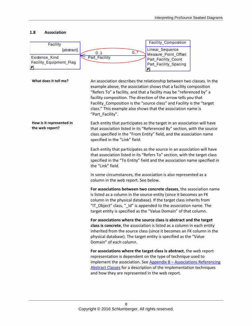
What does it tell me? An association describes the relationship between two classes. In the example above, the association shows that a facility composition “Refers To” a facility, and that a facility may be “referenced by” a facility composition. The direction of the arrow tells you that Facility_Composition is the “source class” and Facility is the “target class.” This example also shows that the association name is “Part_Facility”.
How is it represented in the web report?
Each entity that participates as the target in an association will have that association listed in its “Referenced By” section, with the source class specified in the “From Entity” field, and the association name specified in the “Link” field.
Each entity that participates as the source in an association will have that association listed in its “Refers To” section, with the target class specified in the “To Entity” field and the association name specified in the “Link” field.
In some circumstances, the association is also represented as a column in the web report. See below.
For associations between two concrete classes, the association name is listed as a column in the source entity (since it becomes an FK column in the physical database). If the target class inherits from “IT_Object” class, “_Id” is appended to the association name. The target entity is specified as the “Value Domain” of that column.
For associations where the source class is abstract and the target class is concrete, the association is listed as a column in each entity inherited from the source class (since it becomes an FK column in the physical database). The target entity is specified as the “Value Domain” of each column.
For associations where the target class is abstract, the web report representation is dependent on the type of technique used to implement the association. See Appendix B – Associations Referencing Abstract Classes for a description of the implementation techniques and how they are represented in the web report.
0..*0..1Part_Facility
Facility
{abstract}
Existence_Kind
Facility_Equipment_Flag
Facility_Composition
Linear_Sequence
Measure_Point_Offset
Part_Facility_Count
Part_Facility_Spacing
Interpreting ProSource Seabed Diagrams
9
Copyright © 2016 Schlumberger. All rights reserved.
How is it represented in a physical database?
For associations between two concrete classes, the association becomes a column in the source table with a foreign key constraint in the target table. The column name corresponds to the name of the association unless the target class inherits from the “IT_Object” class, in which case “_Id” is appended to the end of the column name.
For associations where the source class is abstract and the target class is concrete, the association becomes a column in each table whose associated class inherits from the source class. Each column has a foreign key constraint to the target class. The column name corresponds with the name of the association unless the target class inherits from the “IT_Object” class, in which case “_Id” is appended to the end of the column name.
For associations where the target class is abstract, the implementation is dependent on the type of technique specified to implement the association. See Appendix B – Associations Referencing Abstract Classes for a description of the implementation techniques and how they are physically implemented.
1.9 Association Multiplicity
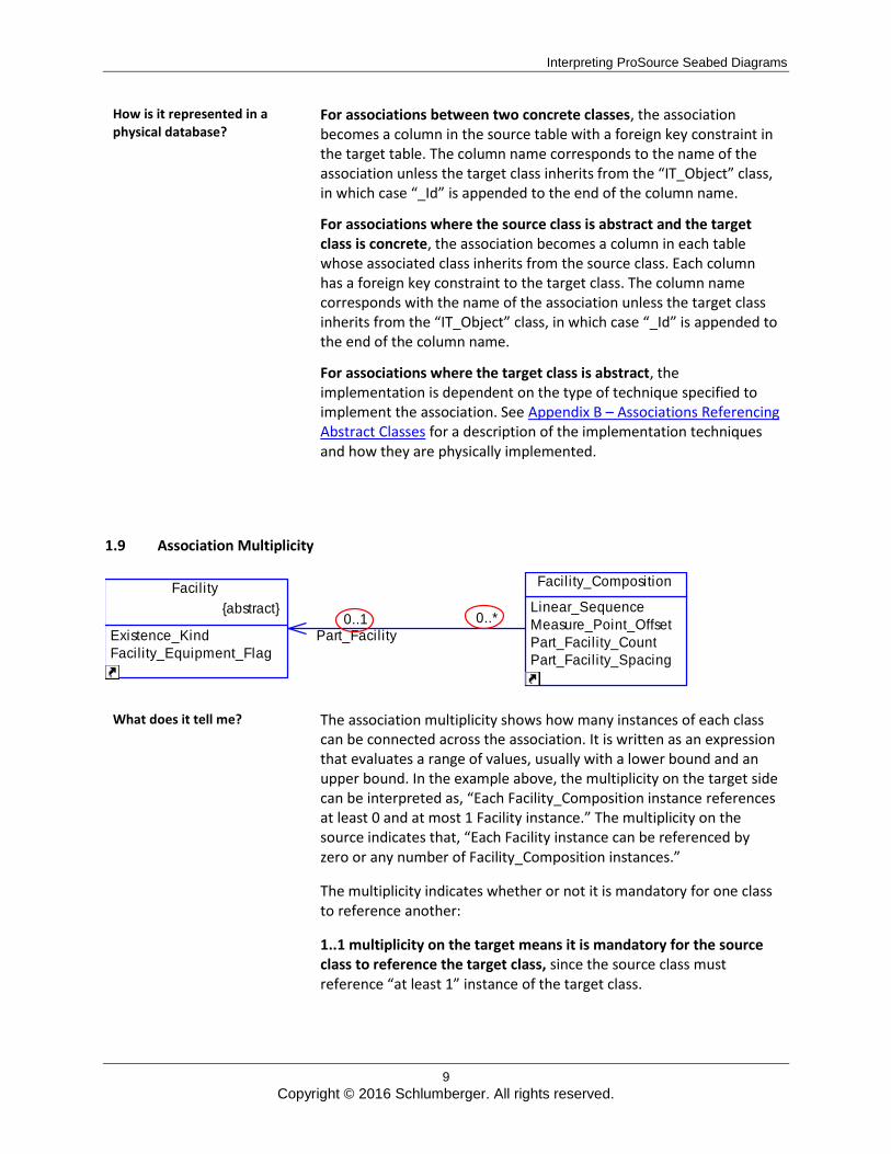
What does it tell me? The association multiplicity shows how many instances of each class can be connected across the association. It is written as an expression that evaluates a range of values, usually with a lower bound and an upper bound. In the example above, the multiplicity on the target side can be interpreted as, “Each Facility_Composition instance references at least 0 and at most 1 Facility instance.” The multiplicity on the source indicates that, “Each Facility instance can be referenced by zero or any number of Facility_Composition instances.”
The multiplicity indicates whether or not it is mandatory for one class to reference another:
1..1 multiplicity on the target means it is mandatory for the source class to reference the target class, since the source class must reference “at least 1” instance of the target class.
0..*0..1Part_Facility
Facility
{abstract}
Existence_Kind
Facility_Equipment_Flag
Facility_Composition
Linear_Sequence
Measure_Point_Offset
Part_Facility_Count
Part_Facility_Spacing
Interpreting ProSource Seabed Diagrams
10
Copyright © 2016 Schlumberger. All rights reserved.
0..1 multiplicity on the target side means it is not mandatory for the source class to reference the target class.
How is it represented in the web report?
The multiplicity is not shown in the web report. The web report shows only whether it is mandatory for the source Entity to reference the target Entity. In this example, the link and column would have a ‘No’ in the “Required” field, since it is not mandatory for a Facility_Composition instance to reference a Facility instance.
How is it represented in a physical database?
For associations between two concrete classes, the association becomes a foreign key column in the source table. If the association is mandatory, the foreign key column is implemented with a NOT NULL constraint.
For associations where the source class is abstract and the target class is concrete, the association becomes a foreign key column in each table whose associated class inherits from the source class. If the association is mandatory, each foreign key column is implemented with a NOT NULL constraint.
For associations where the target class is abstract, see Appendix B – Associations Referencing Abstract Classes for details on how multiplicity for these types of associations is implemented.
Interpreting ProSource Seabed Diagrams
11
Copyright © 2016 Schlumberger. All rights reserved.
1.10 Association Delete Semantic
<<Cascade>> 0..* 0..1
Part_Facility
Facility {abstract}
Existence_Kind Facility_Equipment_Flag
Facility_Composition
Linear_Sequence Measure_Point_Offset Part_Facility_Count Part_Facility_Spacing
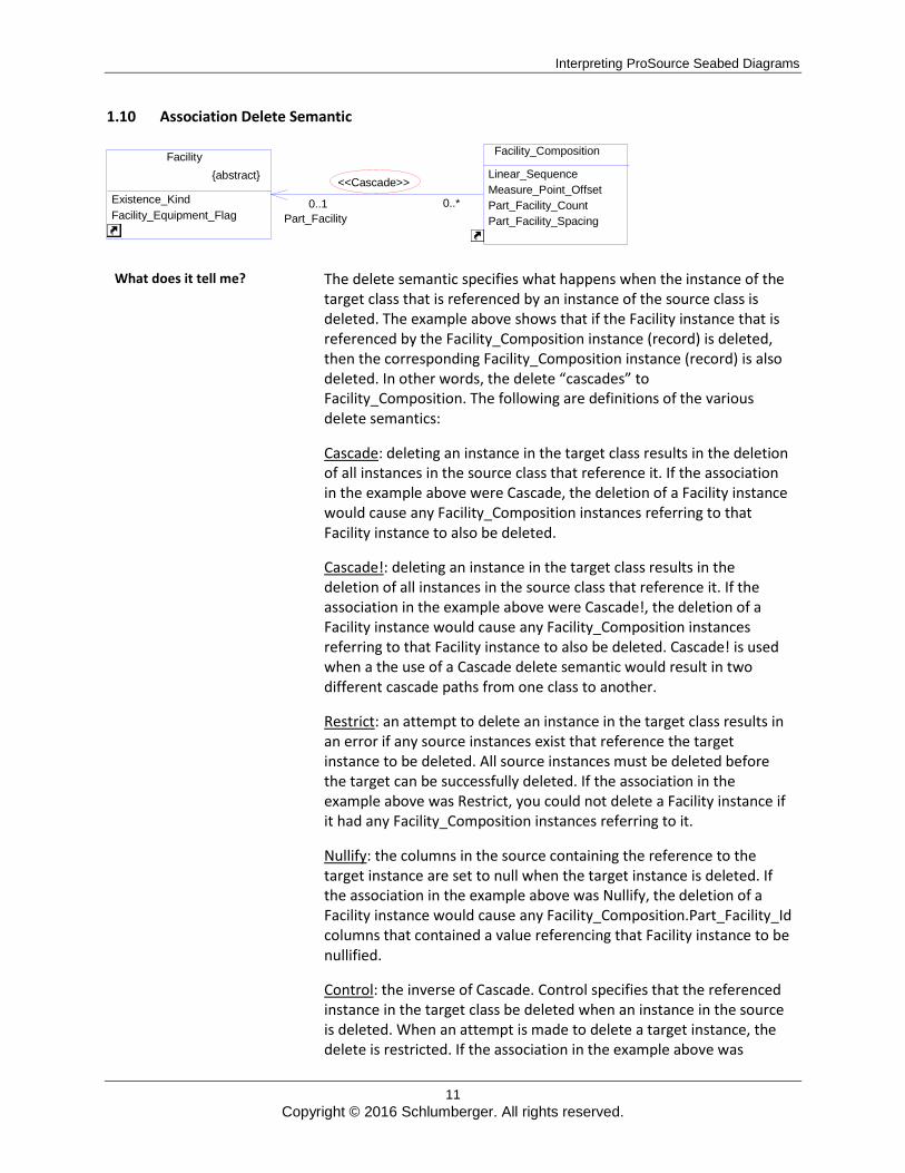
What does it tell me? The delete semantic specifies what happens when the instance of the target class that is referenced by an instance of the source class is deleted. The example above shows that if the Facility instance that is referenced by the Facility_Composition instance (record) is deleted, then the corresponding Facility_Composition instance (record) is also deleted. In other words, the delete “cascades” to Facility_Composition. The following are definitions of the various delete semantics:
Cascade: deleting an instance in the target class results in the deletion of all instances in the source class that reference it. If the association in the example above were Cascade, the deletion of a Facility instance would cause any Facility_Composition instances referring to that Facility instance to also be deleted.
Cascade!: deleting an instance in the target class results in the deletion of all instances in the source class that reference it. If the association in the example above were Cascade!, the deletion of a Facility instance would cause any Facility_Composition instances referring to that Facility instance to also be deleted. Cascade! is used when a the use of a Cascade delete semantic would result in two different cascade paths from one class to another.
Restrict: an attempt to delete an instance in the target class results in an error if any source instances exist that reference the target instance to be deleted. All source instances must be deleted before the target can be successfully deleted. If the association in the example above was Restrict, you could not delete a Facility instance if it had any Facility_Composition instances referring to it.
Nullify: the columns in the source containing the reference to the target instance are set to null when the target instance is deleted. If the association in the example above was Nullify, the deletion of a Facility instance would cause any Facility_Composition.Part_Facility_Id columns that contained a value referencing that Facility instance to be nullified.
Control: the inverse of Cascade. Control specifies that the referenced instance in the target class be deleted when an instance in the source is deleted. When an attempt is made to delete a target instance, the delete is restricted. If the association in the example above was
Interpreting ProSource Seabed Diagrams
12
Copyright © 2016 Schlumberger. All rights reserved.
Control, the Facility instance would be deleted if any Facility_Composition instances that reference it were deleted.
Note: There are a few cases where the diagram specifies a delete semantic that is not actually implemented in the physical database. These cases only arise in associations referencing abstract classes, and are described in detail in the next section. To determine the delete semantic that is actually implemented, refer to the web report.
How is it represented in the web report?
The delete semantic can be inferred from the “Implementation Technique” column for a link in the “Referenced By” or “Refers To” sections.
For associations whose target is a concrete class, the Implementation Technique column displays the delete semantic displayed on the diagram.
For associations whose target is abstract, the Implementation Technique is determined as follows:
For associations that are implemented using the “Assoc” technique and that have a one-to-many cardinality (that is, each source instance can reference one target instance), the implementation technique displays “Assoc to One.” As stated in Appendix B – Associations Referencing Abstract Classes, “Assoc to One” implies a Nullify delete semantic for non-mandatory associations and a Cascade delete semantic for mandatory associations.
For associations that are implemented using the “Assoc” technique and that have a many-to-many cardinality (that is, each source instance can reference many target instances), the implementation technique displays “Assoc to Many.” As stated in Appendix B – Associations Referencing Abstract Classes, “Assoc to Many” implies a Nullify delete semantic.
For associations that are implemented using the “Single Abstract” technique, the implementation technique displays “Cascade”. As described in Appendix B – Associations Referencing Abstract Classes, all associations implemented with the Single Abstract technique trigger a cascade delete.
How is it represented in a physical database?
For associations whose target is a concrete class, the delete semantic is enforced using a database referential integrity constraint.
For associations whose target is abstract, the delete semantic is enforced using alternate methods, which are described in Appendix B – Associations Referencing Abstract Classes.
Interpreting ProSource Seabed Diagrams
13
Copyright © 2016 Schlumberger. All rights reserved.
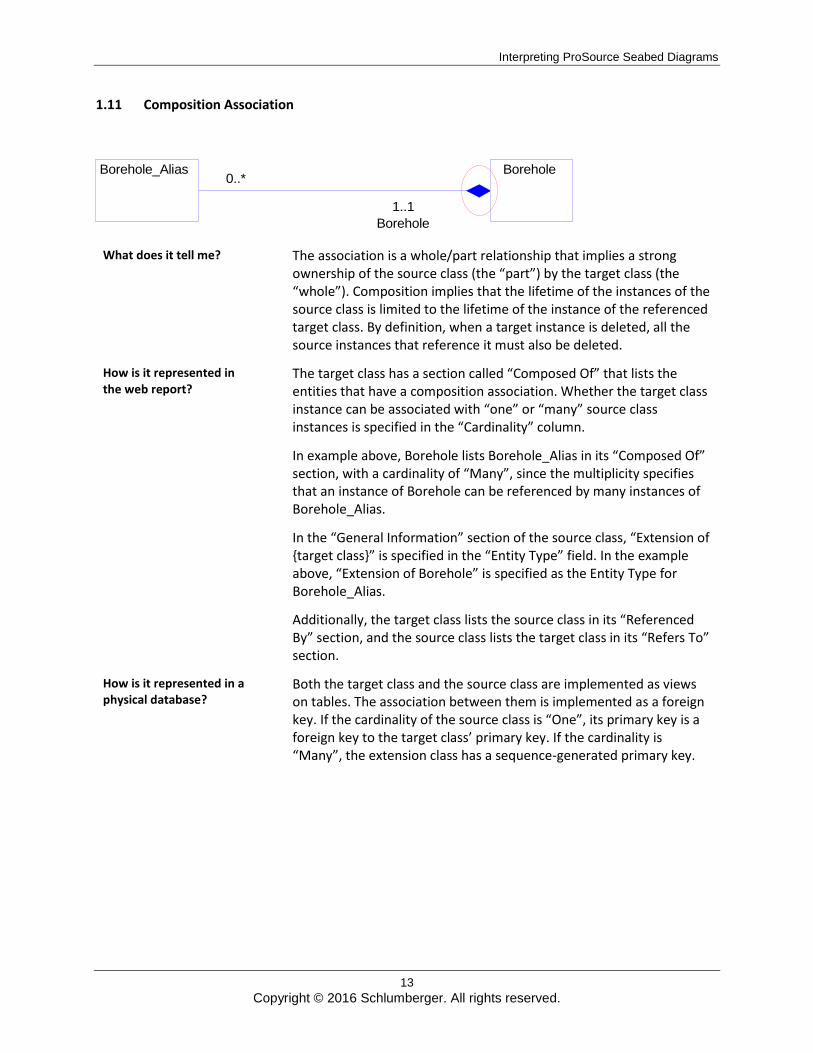
1.11 Composition Association
0..*
1..1 Borehole
Borehole Borehole_Alias
What does it tell me?
The association is a whole/part relationship that implies a strong ownership of the source class (the “part”) by the target class (the “whole”). Composition implies that the lifetime of the instances of the source class is limited to the lifetime of the instance of the referenced target class. By definition, when a target instance is deleted, all the source instances that reference it must also be deleted.
How is it represented in the web report?
The target class has a section called “Composed Of” that lists the entities that have a composition association. Whether the target class instance can be associated with “one” or “many” source class instances is specified in the “Cardinality” column.
In example above, Borehole lists Borehole_Alias in its “Composed Of” section, with a cardinality of “Many”, since the multiplicity specifies that an instance of Borehole can be referenced by many instances of Borehole_Alias.
In the “General Information” section of the source class, “Extension of {target class}” is specified in the “Entity Type” field. In the example above, “Extension of Borehole” is specified as the Entity Type for Borehole_Alias.
Additionally, the target class lists the source class in its “Referenced By” section, and the source class lists the target class in its “Refers To” section.
How is it represented in a physical database?
Both the target class and the source class are implemented as views on tables. The association between them is implemented as a foreign key. If the cardinality of the source class is “One”, its primary key is a foreign key to the target class’ primary key. If the cardinality is “Many”, the extension class has a sequence-generated primary key.
Interpreting ProSource Seabed Diagrams
14
Copyright © 2016 Schlumberger. All rights reserved.
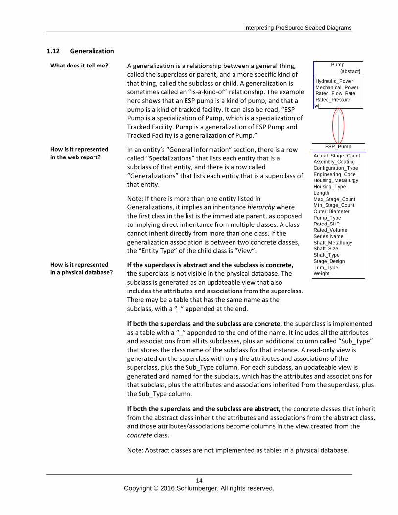
1.12 Generalization
What does it tell me? A generalization is a relationship between a general thing, called the superclass or parent, and a more specific kind of that thing, called the subclass or child. A generalization is sometimes called an “is-a-kind-of” relationship. The example here shows that an ESP pump is a kind of pump; and that a pump is a kind of tracked facility. It can also be read, “ESP Pump is a specialization of Pump, which is a specialization of Tracked Facility. Pump is a generalization of ESP Pump and Tracked Facility is a generalization of Pump.”
How is it represented in the web report?
In an entity’s “General Information” section, there is a row called “Specializations” that lists each entity that is a subclass of that entity, and there is a row called “Generalizations” that lists each entity that is a superclass of that entity.
Note: If there is more than one entity listed in Generalizations, it implies an inheritance hierarchy where the first class in the list is the immediate parent, as opposed to implying direct inheritance from multiple classes. A class cannot inherit directly from more than one class. If the generalization association is between two concrete classes, the “Entity Type” of the child class is “View”.
How is it represented in a physical database?
If the superclass is abstract and the subclass is concrete, the superclass is not visible in the physical database. The subclass is generated as an updateable view that also includes the attributes and associations from the superclass. There may be a table that has the same name as the subclass, with a “_” appended at the end.
If both the superclass and the subclass are concrete, the superclass is implemented as a table with a “_” appended to the end of the name. It includes all the attributes and associations from all its subclasses, plus an additional column called “Sub_Type” that stores the class name of the subclass for that instance. A read-only view is generated on the superclass with only the attributes and associations of the superclass, plus the Sub_Type column. For each subclass, an updateable view is generated and named for the subclass, which has the attributes and associations for that subclass, plus the attributes and associations inherited from the superclass, plus the Sub_Type column.
If both the superclass and the subclass are abstract, the concrete classes that inherit from the abstract class inherit the attributes and associations from the abstract class, and those attributes/associations become columns in the view created from the concrete class.
Note: Abstract classes are not implemented as tables in a physical database.
ESP_Pump
Actual_Stage_Count
Assembly_Coating
Configuration_Type
Engineering_Code
Housing_Metallurgy
Housing_Type
Length
Max_Stage_Count
Min_Stage_Count
Outer_Diameter
Pump_Type
Rated_SHP
Rated_Volume
Series_Name
Shaft_Metallurgy
Shaft_Size
Shaft_Type
Stage_Design
Trim_Type
Weight
Pump
{abstract}
Hydraulic_Power
Mechanical_Power
Rated_Flow_Rate
Rated_Pressure
Interpreting ProSource Seabed Diagrams
15
Copyright © 2016 Schlumberger. All rights reserved.
Appendix A – Association Implementation Techniques Mentioned in the Web Report
Cascade: deleting an instance in the target class results in the deletion of all instances in the source class that reference it.
Restrict: deleting an instance in the target class results in an error if any source instances exist that reference the deleted target instance. All source instances must be deleted before the target can be successfully deleted.
Nullify: the columns in the source containing the reference to the target instance are set to null when the target instance is deleted.
Control: the inverse of Cascade. Control specifies that the referenced instance in the target class be deleted when an instance in the source class is deleted. This is normally used in situations where the target class is referenced from many source classes and a given target instance is referenced from only one instance in one source class. When an attempt is made to delete a target instance, the delete is restricted.
Assoc to One: specified when an association is implemented using the “Assoc” technique (described in Appendix B – Associations Referencing Abstract Classes), and when the association has a one-to-many cardinality; that is, each source instance can reference one target instance and a target can be referenced by many sources.
Assoc to Many: specified when an association is implemented using the “Assoc” technique, (described in Appendix B – Associations Referencing Abstract Classes), and when the association has a many-to-many cardinality; that is, each source instance can reference many target instances and a target can be referenced by many sources.
Interpreting ProSource Seabed Diagrams
16
Copyright © 2016 Schlumberger. All rights reserved.
Appendix B – Associations Referencing Abstract Classes
Relational databases do not support relationships to abstract classes using declarative foreign keys. However, the Seabed database architecture provides alternate ways of specifying relationships to abstract classes. Currently, there are two techniques to accomplish this: “Single Abstract” and “Assoc.” These techniques are explained in detail below.
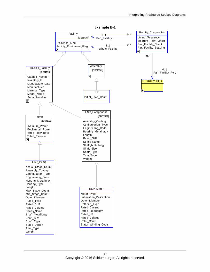
To help illustrate these techniques, consider the scenario where a user wants to specify that an ESP (Electric Submersible Pump) is an assembly made up of an ESP Pump and an ESP Motor. The Seabed class diagram for this structure, called “Facility Composition”, is shown in Example B-1. Facility Composition is a generic mechanism for defining whole facilities that are an assemblance of parts. To specify that an ESP is made up of a pump and a motor, the user would create two Facility_Composition instances: one would specify the ESP Pump as the Part_Facility and the ESP assembly as the Whole_Facility, and the other Facility Composition instance would have ESP Motor as the Part and the same ESP as the Whole Facility.
Specific examples of physical implementation options for these relationships are provided later in this document. In Example B-1, assume that the ESP instance’s primary key (ID) value is 1, the ESP_Pump instance’s primary key value is 5, and the ESP_Motor instance’s primary key value is 9. Also, assume that the first Facility_Composition instance’s primary key value is 7 and the second Facility_Composition instance’s primary key value is 10.
Interpreting ProSource Seabed Diagrams
17
Copyright © 2016 Schlumberger. All rights reserved.
Example B-1
0..*0..1Part_Facility
0..*1..1Whole_Facility
0..*
0..1Part_Facility_Role
ESP
Initial_Start_Count
ESP_Component
{abstract}
Assembly_Coating
Configuration_Type
Engineering_Code
Housing_Metallurgy
Length
Rated_SHP
Series_Name
Shaft_Metallurgy
Shaft_Size
Shaft_Type
Trim_Type
WeightESP_Pump
Actual_Stage_Count
Assembly_Coating
Configuration_Type
Engineering_Code
Housing_Metallurgy
Housing_TypeLength
Max_Stage_Count
Min_Stage_Count
Outer_Diameter
Pump_Type
Rated_SHP
Rated_Volume
Series_Name
Shaft_Metallurgy
Shaft_Size
Shaft_Type
Stage_Design
Trim_Type
Weight
ESP_Motor
Motor_Type
Lubrication_Description
Outer_Diameter
Pothead_Type
Rated_Current
Rated_Frequency
Rated_HP
Rated_Voltage
Rotor_Count
Stator_Winding_Code
Facility
{abstract}
Existence_Kind
Facility_Equipment_Flag
Facility_Composition
Linear_Sequence
Measure_Point_Offset
Part_Facility_Count
Part_Facility_Spacing
R_Facility_Role
Assembly
{abstract} Tracked_Facility
{abstract}
Catalog_Number
Inventory_Id
Manufacture_Date
Manufacturer
Material_Type
Model_Name
Serial_Number
Pump
{abstract}
Hydraulic_Power
Mechanical_Power
Rated_Flow_Rate
Rated_Pressure
0..*
Interpreting ProSource Seabed Diagrams
18
Copyright © 2016 Schlumberger. All rights reserved.
B.1 Single Abstract
“Single Abstract” is one alternative for specifying relationships to abstract classes. It is an implementation technique that applies only to one-to-many associations where the target is abstract. In other words, the “single” component of the name refers to the fact that the cardinality on the target side is ‘1’. The “abstract” component of the name refers to the fact that the target is an abstract class. In Example B-1 above, the “Whole_Facility” and “Part_Facility” associations fall into this category.
B.1.1 Physical Implementation
When the Single Abstract implementation technique is specified for an association, the association is implemented physically as follows:
The source table is implemented with the following two columns, the combination of which store the reference to the target: o {Association Name}_ID: stores the PK value of the target instance. o {Association Name}_TBL: stores the name of the table in which the target instance
resides.
B.1.1.1 Referential Integrity
When the Single Abstract implementation technique is specified for an association, the referential integrity is handled as follows: 1. A delete trigger is added to each table that implements a concrete class that inherits from
the target. The trigger deletes the referencing source record instance when the target record instance is deleted. This essentially implements a cascade delete for every association implemented with the Single Abstract technique.
2. There is no referential integrity built in for updates to the {Association Name}_ID or {Association Name}_TBL columns, meaning no data validation is performed. Therefore, the application or user must ensure that the values are valid.
B.1.1.2 Multiplicity
If the association specifies a mandatory reference to the target, the {Association Name}_ID and {Association Name}_TBL columns are implemented with NOT NULL constraints.
B.1.1.3 Web Report Representation
When the Single Abstract implementation technique is specified for an association, the association is represented in the web report as follows: 1. The association is listed in the “Refers To” or “Referenced By” section of the web report.
The implementation technique is “Cascade”. If the reference to the abstract class is mandatory, a “Yes” is in the “Required” column.
2. Two columns, {Association Name}_ID and {Association Name}_TBL, are listed in the “Columns” section. The _ID column specifies the abstract class as its domain; and the _TBL column specifies Meta_Entity as its domain. If the reference to the abstract class is mandatory, both the _ID and the _TBL columns are specified as “Required.”
Interpreting ProSource Seabed Diagrams
19
Copyright © 2016 Schlumberger. All rights reserved.
B.1.1.4 Data Example
In Example B-1, if the Whole_Facility and Part_Facility associations were implemented using the Single Abstract technique, the table representing the Facility_Composition table would be implemented with the following additional columns:
Whole_Facility_Id, Whole_Facility_Tbl
Part_Facility_Id, Part_Facility_Tbl The records created in Facility_Composition to store the fact that an ESP is made up of an ESP pump and motor would have the following values:
Record 1 – for the pump: – Whole_Facility_Id would store a value of ‘1’ (the identifier of the ESP assembly). – Whole_Facility_Tbl would store a value of “ESP.” – Part_Facility_Id would store a value of ‘5’ (the identifier of the ESP_Pump record). – Part_Facility_Tbl would store a value of “ESP_Pump.”
Record 2 – for the motor: – Whole_Facility_Id would store a value of ‘1’ (the identifier of the ESP assembly). – Whole_Facility_Tbl would store a value of “ESP.” – Part_Facility_Id would store a value of ‘9’ (the identifier of the ESP_Motor record). – Part_Facility_Tbl would store a value of “ESP_Motor.”
B.1.2 Assoc
The other method to specify associations to abstract classes is called “Assoc.” This is the only method to use when the association is many-to-many, but can also be used for one-to-many associations.
B.1.1.5 Physical Implementation
When the Assoc implementation technique is specified for an association, the association is physically implemented as follows:
1. The table generated from the source class has no columns that reference the target. Instead, information about association instances is stored in a special table called Assoc. The Assoc table is made up of the following columns:
Entity_Type - The name of the entity on the “source” (referencing) side of the association. This is analogous to the name of the table holding the FK column in a relational database.
Note: The entity name is not validated against the list of entity names in the database.
Entity_Id - The identifier of the record on the “source” side of the association. It is the identifier of the record that is referencing the other (as opposed to being referenced by the other). This is analogous to the value of the PK of the record holding the FK value in a relational database.
Note: The id is not validated against the list of valid IDs in the source.
Property_Type - The name of the entity on the “target” (referenced) side of the
Interpreting ProSource Seabed Diagrams
20
Copyright © 2016 Schlumberger. All rights reserved.
association. This is analogous to the name of the table the FK column is referencing in a relational database.
Note: The entity name is not validated against the list of entity names in the database.
Property_Code - The name of the role played by the “target” (referenced) record. This is analogous to the name of the FK column in a relational database. In QDesigner’s implementation of UML, this is the Role B Name.
Property_Id - The identifier of the record on the “target” side of the association. It is the identifier of the record that is being referenced by the other. This is analogous to the value in the FK column in a relational database.
Note: The id is not validated against the list of valid IDs in the target.
Rank - The order of the referenced entity instances when there are “many” instances on the target (referenced) side of the association.
2. If the class on the source side of the association has no subtypes, an updateable view called {Source Class Name}_Ref is created. This view sits on top of the Assoc table and has the same columns as Assoc, with the exception of Entity_Type, whose value can be inferred from the view name. If the source class has subtypes, the view’s name is based on the name of the concrete class that inherits from the source class.
B.1.1.6 Referential Integrity
When the Assoc implementation technique is specified for an association, the referential integrity is handled as follows: 1. A delete trigger is added to each table that implements a concrete class that inherits from
the target. The trigger’s behavior is dependent on the multiplicity of the association:
If the reference to the target class is optional: When a record in the target is deleted, the trigger deletes all records in Assoc that reference that target instance. This essentially implements a nullify delete constraint for the association.
If the reference to the target class is mandatory: When a record in the target is deleted, the delete trigger deletes all records in Assoc that reference that target instance and the record that is referencing the target. This means that the record whose identifier is stored in the Entity_Id column in the record is deleted from Assoc. This essentially implements a cascade delete constraint for the association. In Example B-1, if the ESP #1 record were deleted, every row in Assoc that has Property_Id = 1 and Property_Type = ‘ESP’ would be deleted. In addition, the Facility_Composition #7 record would be deleted.
2. There is no built-in referential integrity for updates to any column in the ASSOC table; therefore, no data validation is performed. The application or user must ensure that the values are valid.
Interpreting ProSource Seabed Diagrams
21
Copyright © 2016 Schlumberger. All rights reserved.
B.1.1.7 Multiplicity
It is currently not possible to enforce an insert into the Assoc table for associations that are implemented with the Assoc technique and are specified as mandatory. Users or applications must ensure that the proper records are inserted into the Assoc table.
B.1.1.8 Web Report Representation
When the Assoc implementation technique is specified for an association, the association is represented in the web report as follows:
The association is listed in the “Refers To” or “Referenced By” section of the web report. The implementation technique is “Assoc to One” if only one instance of the target class can be referenced (the multiplicity on the target side is 1..1 or 0..1). The implementation technique is “Assoc to Many” if many instances of the target class can be referenced (the multiplicity on the target side is 1..* or 0..*). If the reference to the target class is mandatory, there is a “Yes” in the “Required” column, which implies a Cascade delete behavior across the association. If the reference to the target class is not mandatory, there is a “No” in the “Required” column, which implies a Nullify delete behavior across the association.
B.1.1.9 Data Example
In Example B-1, if the Whole_Facility and Part_Facility associations were implemented using the Assoc technique, an updateable view would be created on top of the Assoc table called Facility_Composition_Ref. To store the fact that an ESP is made up of an ESP pump and motor, a user would insert four records into this view as follows:
Records for ESP Pump and ESP: – Entity_Id – This column would contain the value “7” for both the record storing the
“Whole_Facility” association and the record storing the “Part_Facility” association. This value is the identifier of the Facility_Composition record that is recording the fact that the ESP is made up of the ESP pump.
– Property_Type – This column would contain the value “ESP” for the record storing the “Whole_Facility” association and the value “ESP_Pump” for the record storing the “Part_Facility” association.
– Property_Code – This column would contain the value “Whole_Facility” for the record storing the “Whole_Facility” association and the value “Part_Facility” for the record storing the “Part_Facility” association.
– Property_Id – This column would contain the value “1” (the identifier of the ESP record) for the record storing the “Whole_Facility” association and the value “5” (the identifier of the ESP_Pump record) for the record storing the “Part_Facility” association.
– Rank – This column would contain the value “0” for both the record storing the “Whole_Facility” association and for the record storing the “Part_Facility” association because this is a one-to-many relationship.
Interpreting ProSource Seabed Diagrams
22
Copyright © 2016 Schlumberger. All rights reserved.
Records for ESP Motor and ESP: – Entity_Id – This column would contain the value “10” for both the record storing the
“Whole_Facility” association and for the record storing the “Part_Facility” association. This value is the identifier of the Facility_Composition record that is recording the fact that the ESP is made up of the ESP motor.
– Property_Type – This column would contain the value “ESP” for the record storing the “Whole_Facility” association and the value “ESP_Motor” for the record storing the “Part_Facility” association.
– Property_Code – This column would contain the value “Whole_Facility” for the record storing the “Whole_Facility” association and the value “Part_Facility” for the record storing the “Part_Facility” association.
– Property_Id – This column would contain the value “1” (the identifier of the ESP record) for the record storing the “Whole_Facility” association and the value “9” (the identifier of the ESP_Motor record) for the record storing the “Part_Facility” association.
– Rank – This column would contain the value “0” for both the record storing the “Whole_Facility” association and the record storing the “Part_Facility” association because this is a one-to-many relationship.
This view would in turn populate the underlying Assoc table with four records whose Entity_Type column is “Facility_Composition.”