Embed Size (px)
Citation preview
SCSJ2203: Software Engineering
Software Design Document
Project Title
Version 1.0
Printing Date
Department and Faculty
Prepared by: <Give your group a name>
ii
SDD-Template-v1.1-SCSJ2203-SE@UTM-BySAH-2May2016
Revision Page
a. Overview
Describe the content of the current version.
b. Target Audience
State the targeted audience.
c. Project Team Members
List the team members and respective assigned module.
d. Version Control History
Version Primary
Author(s)
Description of
Version
Date
Completed
<Current Version>
Note: This template is an annotated outline for a software design document adapted from the IEEE Recommended Practice for Software Design Descriptions. The IEEE Recommended Practice for Software Design Descriptions have been reduced in order to simplify this assignment while still retaining the main components and providing a general idea of a project definition report. Please refer to IEEE Std 10161998 1 for the full IEEE Recommended Practice for Software Design Descriptions. Examples of models are from Satzinger (2011). Compiled by Shahliza Abdul Halim, PhD and checked by Shahida Sulaiman, PhD on 2 May 2016.
iii
Table of Contents
1 Introduction 1
1.1 Purpose 1
1.2 Scope
1.3 Definitions, Acronyms and Abbreviations
1.4 Reference Materials
1.5 System Overview
2 System Architectural Design
2.1 Architectural Style and Rationale
2.2 Component Model
2.3 Use Case Diagram
3 Detailed Description of Modules
3.1 Complete Package Diagram
3.2 Modules Detailed Descriptions
3.2.1 Module <Name of Module 1>
3.2.1.1 Package Diagram
3.2.1.2 Class Diagram
3.2.1.3 Sequence Diagrams
3.2.2 Module <Name of Module 2>
3.2.2.1 Package Diagram
3.2.2.2 Class Diagram
3.2.2.3 Sequence Diagrams
3.2.3 Module <Name of the n Module>
3.2.3.1 Package Diagram
3.2.3.2 Class Diagram
3.2.2.3 Sequence Diagrams
iv
4 Data Design
4.1 Data Description
4.2 Data Dictionary
5 User Interface Design
5.1 Overview of User Interface
5.2 Screen Images
6 Requirements Matrix
7 Appendices
Appendices (if any)
1
1. Introduction
The following section and subsections of the Software Design Documents (SDD)
document should provide the details of the entire SDD. Remove the notes in read
texts including these notes.
1.1 Purpose
Identify the purpose of this SDD and its intended audience. (e.g. “This software design document describes the architecture and detailed design of System XX. ….”).
This SDD describes…
1.2 Scope
Provide a description and scope of the software and explain the goals, objectives and benefits of your project. This will
provide the basis for the brief description of your product.
The software product is…
1.3 Definitions, Acronyms and Abbreviation
Provide definitions of all terms, acronyms, and abbreviations that might exist to properly interpret the SDD.
These definitions should be items used in the SDD that are most likely not known to the audience.
Definitions of all terms, acronyms and abbreviation used are to be defined here.
1.4 References
List any documents, if any, which were used as sources of information for the SDD.
This subsection should:
a) Provide a complete list of all documents referenced elsewhere in the SDD; b) Identify each document by title, report number (if applicable), date, and publishing organization; c) Specify the sources from which the references can be obtained.
Specify complete list of references using a standardized reference format.
1.5 Overview
Give a general description of the functionality, context and design of your project. Provide any
background information if necessary.
This subsection should also:
a) Describe what the rest of the SDD contains; b) Explain how the SDD is organized.
2
2. System Architectural Design
This section of the SDD should describe the architectural style and the rationale or justification of your selection. The
component and subsystem diagram should also be included.
2.1 Architecture Style and Rationale
State your chosen architectural style and the rationale of choosing that particular style
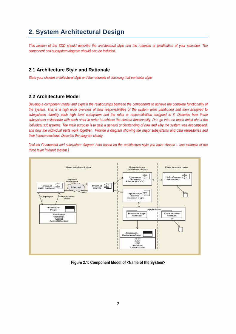
2.2 Architecture Model
Develop a component model and explain the relationships between the components to achieve the complete functionality of
the system. This is a high level overview of how responsibilities of the system were partitioned and then assigned to
subsystems. Identify each high level subsystem and the roles or responsibilities assigned to it. Describe how these
subsystems collaborate with each other in order to achieve the desired functionality. Don go into too much detail about the
individual subsystems. The main purpose is to gain a general understanding of how and why the system was decomposed,
and how the individual parts work together. Provide a diagram showing the major subsystems and data repositories and
their interconnections. Describe the diagram clearly.
[Include Component and subsystem diagram here based on the architecture style you have chosen – see example of the
three layer internet system.]
Figure 2.1: Component Model of <Name of the System>
3
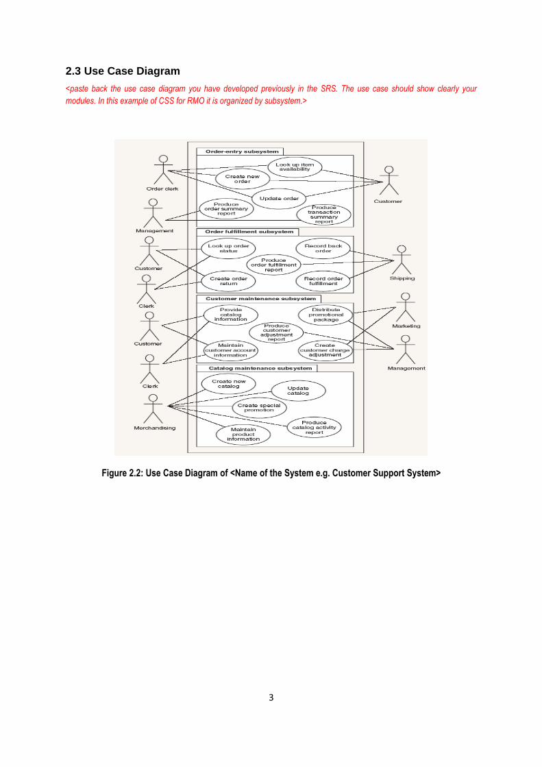
2.3 Use Case Diagram
<paste back the use case diagram you have developed previously in the SRS. The use case should show clearly your
modules. In this example of CSS for RMO it is organized by subsystem.>
Figure 2.2: Use Case Diagram of <Name of the System e.g. Customer Support System>
4
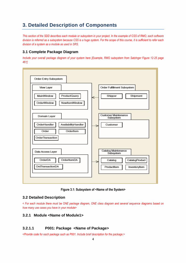
3. Detailed Description of Components
This section of the SDD describes each module or subsystem in your project. In the example of CSS of RMO, each software
division is referred as a subsystem because CSS is a huge system. For the scope of this course, it is sufficient to refer each
division of a system as a module as used in SRS.
3.1 Complete Package Diagram
Include your overall package diagram of your system here [Example, RMO subsystem from Satzinger Figure 12-25 page
461]
Figure 3.1: Subsystem of <Name of the System>
3.2 Detailed Description
< For each module there must be ONE package diagram, ONE class diagram and several sequence diagrams based on
how many use cases you have in your module>
3.2.1 Module <Name of Module1>
3.2.1.1 P001: Package <Name of Package>
<Provide code for each package such as P001. Include brief description for the package.>
5
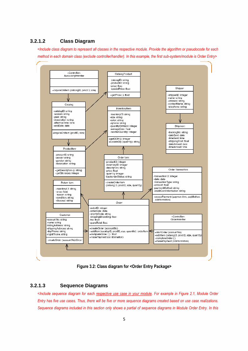
3.2.1.2 Class Diagram
<Include class diagram to represent all classes in the respective module. Provide the algorithm or pseudocode for each
method in each domain class (exclude controller/handler). In this example, the first sub-system/module is Order Entry>
Figure 3.2: Class diagram for <Order Entry Package>
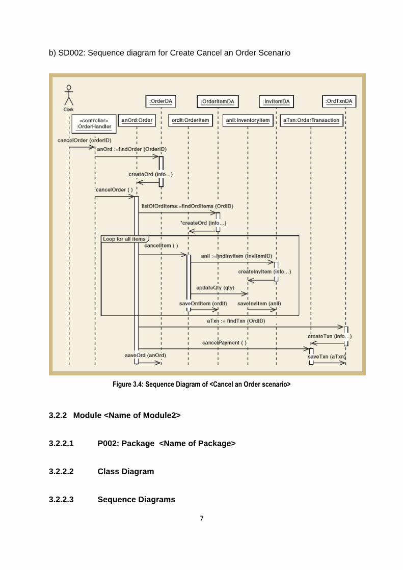
3.2.1.3 Sequence Diagrams
<Include sequence diagram for each respective use case in your module. For example in Figure 2.1, Module Order
Entry has five use cases. Thus, there will be five or more sequence diagrams created based on use case realizations.
Sequence diagrams included in this section only shows a partial of sequence diagrams in Module Order Entry. In this
6
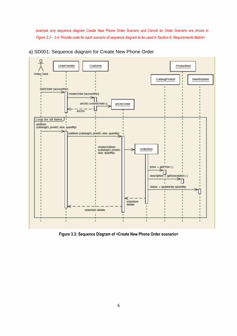
example only sequence diagram Create New Phone Order Scenario and Cancel an Order Scenario are shown in
Figure 3.3 – 3.4. Provide code for each scenario of sequence diagram to be used in Section 6: Requirements Matrix>
a) SD001: Sequence diagram for Create New Phone Order
Figure 3.3: Sequence Diagram of <Create New Phone Order scenario>
7
b) SD002: Sequence diagram for Create Cancel an Order Scenario
Figure 3.4: Sequence Diagram of <Cancel an Order scenario>
3.2.2 Module <Name of Module2>
3.2.2.1 P002: Package <Name of Package>
3.2.2.2 Class Diagram
3.2.2.3 Sequence Diagrams
8
3.2.3 Module <Name of n Module>
3.2.3.1 n: Package <Name of Package>
3.2.3.2 Class Diagram
3.2.3.3 Sequence Diagrams
9
4. Data Design
4.1 Data Description
Explain how the information domain of your system is transformed into data structures. Describe how the major data or
system entities are stored, processed and organized. List the database(s) or data storage items. For a small system,
there is normally only one database. It consists of all the tables in which for object-oriented they are classes/objects.
Use table for the listing.
4.2 Data Dictionary
Alphabetically list the system entities or major data along with their types and descriptions (class/object, attributes,
methods and method parameters). Focus on classes in domain layer; omit the controller/handler class. Use tables for
easy listing.
10
5. User Interface Design
5.1 Overview of User Interface
Describe the functionality of the system from the user’s perspective. Explain how the user will be able to use your
system to complete all the expected features and the feedback information that will be displayed for the user.
5.2 Screen Images
Display screenshots showing the interface from the user’s perspective. These can be drawn using an automated
drawing tool. Just make them as accurate as possible.
11
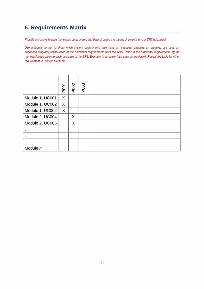
6. Requirements Matrix
Provide a cross-reference that traces components and data structures to the requirements in your SRS document.
Use a tabular format to show which system components (use case vs. package, package vs. classes, use case vs.
sequence diagram) satisfy each of the functional requirements from the SRS. Refer to the functional requirements by the
numbers/codes given to each use case in the SRS. Example is as below (use case vs. package). Repeat the table for other
requirement vs. design elements.
P0
01
P0
02
P0
03
…
Module 1, UC001 X
Module 1, UC002 X
Module 1, UC002 X
Module 2, UC004 X
Module 2, UC005 X
.
.
.
Module n

12
7. Appendices
Provide appendices if any.