Embed Size (px)
Citation preview

SCSJ2203: Software Engineering
Software Design Document
UTM Green School System
Version 2.0
15th May 2016
Faculty of Computing UTM
Prepared by: We Built Legoland
ii
Revision Page
a. Overview
The current version provide an introduction to the UTM Green School System, system
architectural design, detail description of modules, data design, user interface design
and requirement matrix of the system.
b. Target Audience
The targeted audience would be the development team.
c. Project Team Members
Module 1 Login: Siti Amira binti Khairul Anuar
Module 2 Assignment: Raymond Tan Wei Yi
Module 3 Examination: Siti Amira binti Khairul Anuar
Module 4 Green: Ahmad Helmi Afiq bin Norazman
d. Version Control History
Version Primary Author(s) Description of Version Date Completed
1.0 Raymond Tan Wei Yi
Siti Amira binti Khairul
Anuar
Ahmad Helmi Afiq bin
Norazman
Initial Document
Creation.
Inclusive of Class
Diagram, Package
Diagram and Sequence
Diagram
11th May 2016
iii
2.0 Raymond Tan Wei Yi
Siti Amira binti Khairul
Anuar
Ahmad Helmi Afiq bin
Norazman
Inclusive of User
Interface Design, Data
Design and Requirement
Matrix
13th May 2016
iv
Table of Contents
1 Introduction
1.1 Purpose 1
1.2 Scope 1
1.3 Definitions, Acronyms and Abbreviations 2
1.4 Reference Materials 2
1.5 System Overview 2
2 System Architectural Design
2.1 Architectural Style and Rationale 3
2.2 Component Model 3
2.3 Use Case Diagram 4
3 Detailed Description of Modules
3.1 Complete Package Diagram 5
3.2 Modules Detailed Descriptions 6
3.2.1 M - 01 Module Login 6
v
3.2.1.1 Package Diagram 6
3.2.1.2 Class Diagram 7
3.2.1.3 Methods 7
3.2.1.4 Sequence Diagrams 8
3.2.2 M - 02 Module Assignment 9
3.2.2.1 Package Diagram 9
3.2.2.2 Class Diagram 10
3.2.2.3 Methods 10
3.2.2.4 Sequence Diagrams 14
3.2.3 M - 03 Module Examination 17
3.2.3.1 Package Diagram 17
3.2.3.2 Class Diagram 18
3.2.3.3 Methods 18
3.2.3.4 Sequence Diagrams 21
3.2.4 M - 04 Module Green 24
vi
3.2.4.1 Package Diagram 24
3.2.4.2 Class Diagram 25
3.2.4.3 Methods 26
3.2.4.4 Sequence Diagrams 27
4 Data Design
4.1 Data Description 30
4.2 Data Dictionary 31
5 User Interface Design
5.1 Overview of User Interface 36
5.2 Screen Images 38
6 Requirement Matrix
6.1 Use Case vs Package 52
6.2 Package vs Sequence Diagram 53
6.3 Sequence Diagram vs Class 54
1
1. Introduction
1.1 Purpose
The purpose of this Software Design Document (SDD) written is to describe the
architecture and detailed design of Green School System. This includes the
architectural features of the system down through details of what operations each code
module will perform and the database layout. It also shows how the use cases detailed
in the SRS will be implemented in the system using this design. In addition, it gives the
user interface design to show how the system will work with user. The primary
audiences of this document are the software developers.
1.2 Scope
The software product is Green School System – a platform connecting student
database with elearning system/Aimsweb UTM and a social media page promoting
eco-friendliness. It allows examination updates, social media page for green info
sharing and assignment notification. Examination updates include examination
timetable; Students can view timetable while faculty admin update the latest
examination timetable. For assignment, the system will give notification when there is
an assignment have to be submitted and still, student have to go to elearning to submit
the particular assignment. This is because the system does not provide a link for
assignment submission. Last main feature is social media page. Here, green committee
will share green info and any updates about green activity that is conducted in UTM or
organized by UTM at the outside.
Primarily, the system is developed to fulfill UTM sustainability goal. It conserve
the environment by encouraging eco-friendly behavior by cutting paper usage and
promote eco-friendly awareness. The core purpose of the system is to computerize
paper documents of students’ examination, assignment and timetable by eliminating
redundant printing. In this system, several existing system such as elearning and
2
AIMSWEB will be incorporated in the new system. The final outcome would be reduced
paper usage which in return saves more tree. With the product, the client can save at
least 50,000 piece of paper per annum.
1.3 Definitions, Acronyms and Abbreviation
Term/Acronym/Abbreviation Definition
Green Info Info, fact or knowledge about saving world resources
such as benefits of reducing paper usage
Green Activity Activity that involves in saving world resources that is
done inside or outside UTM
Local Area Network (LAN) A network that connects computers and other devices
in a relatively small area, typically a single building or a
group of buildings.
1.4 References
1. http://elearning.utm.my/15162/
2. http://aimsweb.utm.my/
1.5 Overview
The remaining sections of this document contains:
Section 2: describes the architectural style and the rationale;
Section 3: describes each module in the system;
Section 4: describes the database layout and attributes involved;
Section 5: describes user interface design.
3
2. System Architectural Design
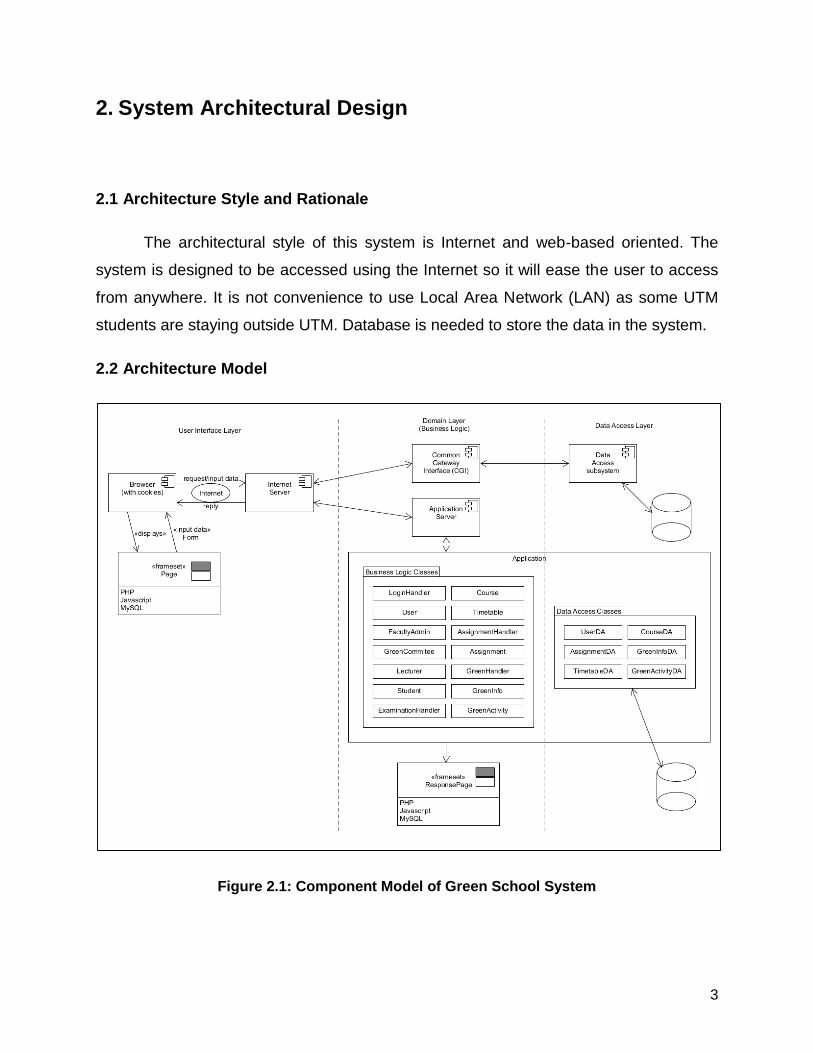
2.1 Architecture Style and Rationale
The architectural style of this system is Internet and web-based oriented. The
system is designed to be accessed using the Internet so it will ease the user to access
from anywhere. It is not convenience to use Local Area Network (LAN) as some UTM
students are staying outside UTM. Database is needed to store the data in the system.
2.2 Architecture Model
Figure 2.1: Component Model of Green School System
4
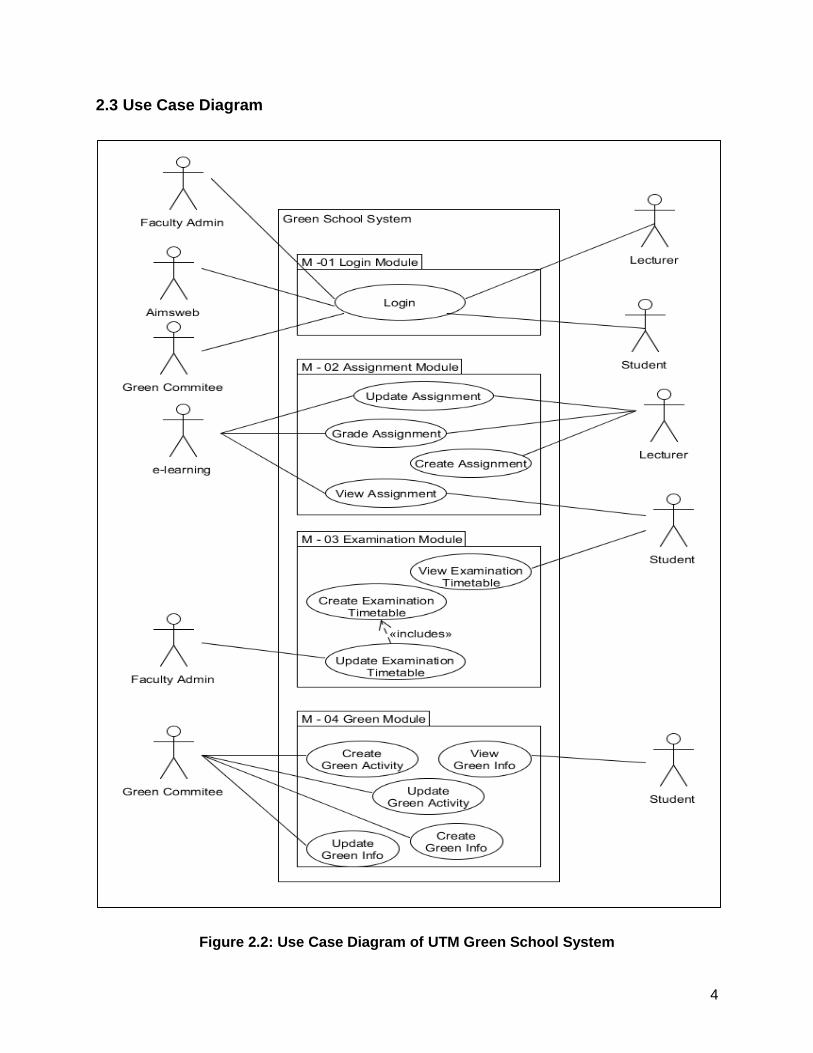
2.3 Use Case Diagram
Figure 2.2: Use Case Diagram of UTM Green School System
5
3. Detailed Description of Components
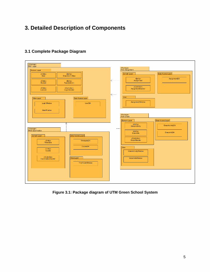
3.1 Complete Package Diagram
Figure 3.1: Package diagram of UTM Green School System
6
3.2 Detailed Description
The following section describe the 4 modules in details which are, Login Module,
Assignment Module, Examination Module and Green Module. Each module has a
package diagram, a class diagram and several sequence diagram.
3.2.1 M-01: Module Login
This module covers all the function that is related to login and user type.
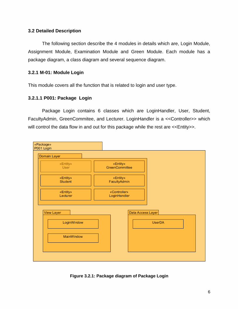
3.2.1.1 P001: Package Login
Package Login contains 6 classes which are LoginHandler, User, Student,
FacultyAdmin, GreenCommitee, and Lecturer. LoginHandler is a <<Controller>> which
will control the data flow in and out for this package while the rest are <<Entity>>.
Figure 3.2.1: Package diagram of Package Login
7
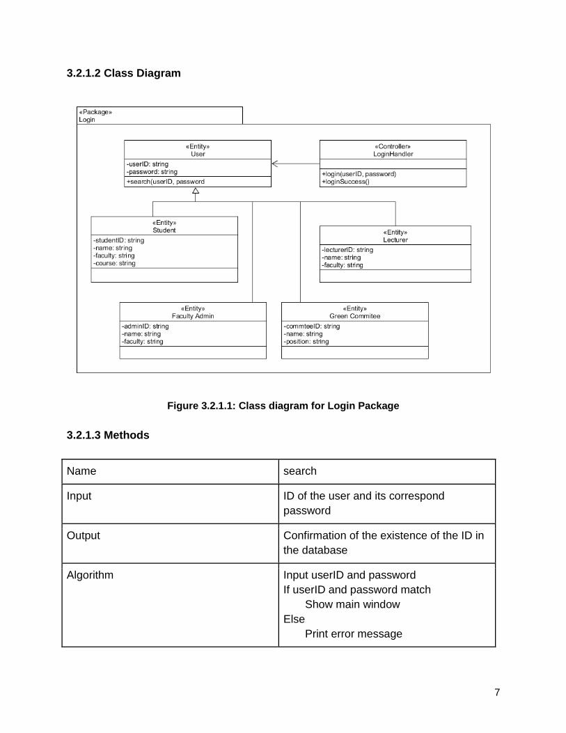
3.2.1.2 Class Diagram
Figure 3.2.1.1: Class diagram for Login Package
3.2.1.3 Methods
Name search
Input ID of the user and its correspond
password
Output Confirmation of the existence of the ID in
the database
Algorithm Input userID and password
If userID and password match
Show main window
Else
Print error message
8
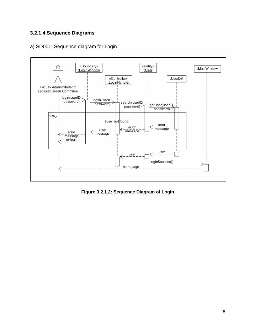
3.2.1.4 Sequence Diagrams
a) SD001: Sequence diagram for Login
Figure 3.2.1.2: Sequence Diagram of Login
9
3.2.2 M – 02: Module Assignment
This module covers the function that has to do with assignment.
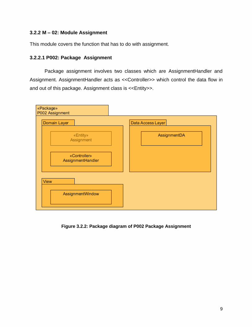
3.2.2.1 P002: Package Assignment
Package assignment involves two classes which are AssignmentHandler and
Assignment. AssignmentHandler acts as <<Controller>> which control the data flow in
and out of this package. Assignment class is <<Entity>>.
Figure 3.2.2: Package diagram of P002 Package Assignment
10
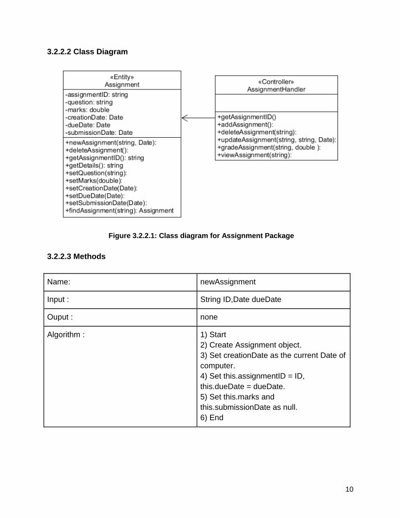
3.2.2.2 Class Diagram
Figure 3.2.2.1: Class diagram for Assignment Package
3.2.2.3 Methods
Name: newAssignment
Input : String ID,Date dueDate
Ouput : none
Algorithm : 1) Start
2) Create Assignment object.
3) Set creationDate as the current Date of
computer.
4) Set this.assignmentID = ID,
this.dueDate = dueDate.
5) Set this.marks and
this.submissionDate as null.
6) End
11
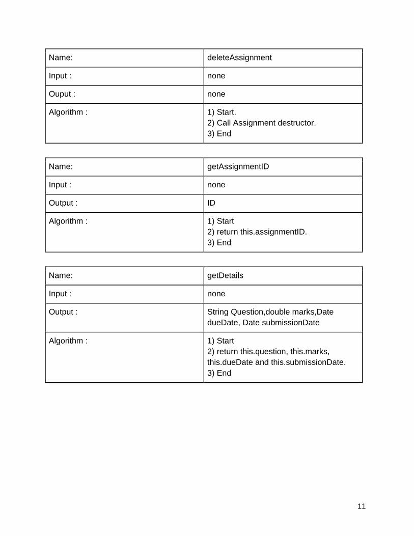
Name: deleteAssignment
Input : none
Ouput : none
Algorithm : 1) Start.
2) Call Assignment destructor.
3) End
Name: getAssignmentID
Input : none
Output : ID
Algorithm : 1) Start
2) return this.assignmentID.
3) End
Name: getDetails
Input : none
Output : String Question,double marks,Date
dueDate, Date submissionDate
Algorithm : 1) Start
2) return this.question, this.marks,
this.dueDate and this.submissionDate.
3) End
12
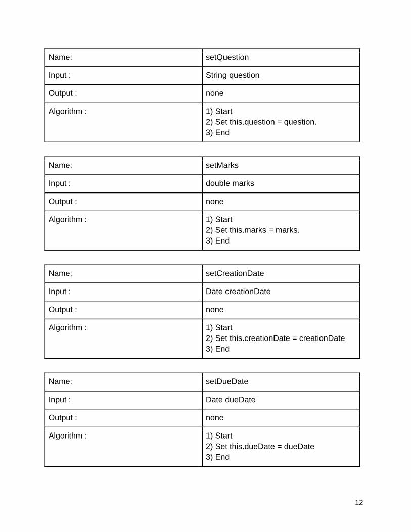
Name: setQuestion
Input : String question
Output : none
Algorithm : 1) Start
2) Set this.question = question.
3) End
Name: setMarks
Input : double marks
Output : none
Algorithm : 1) Start
2) Set this.marks = marks.
3) End
Name: setCreationDate
Input : Date creationDate
Output : none
Algorithm : 1) Start
2) Set this.creationDate = creationDate
3) End
Name: setDueDate
Input : Date dueDate
Output : none
Algorithm : 1) Start
2) Set this.dueDate = dueDate
3) End
13
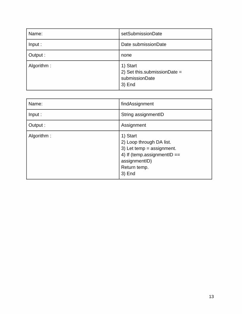
Name: setSubmissionDate
Input : Date submissionDate
Output : none
Algorithm : 1) Start
2) Set this.submissionDate =
submissionDate
3) End
Name: findAssignment
Input : String assignmentID
Output : Assignment
Algorithm : 1) Start
2) Loop through DA list.
3) Let temp = assignment.
4) If (temp.assignmentID ==
assignmentID)
Return temp.
3) End
14
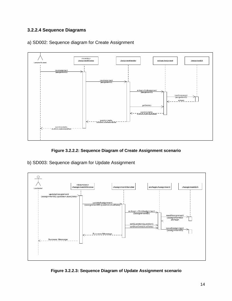
3.2.2.4 Sequence Diagrams
a) SD002: Sequence diagram for Create Assignment
Figure 3.2.2.2: Sequence Diagram of Create Assignment scenario
b) SD003: Sequence diagram for Update Assignment
Figure 3.2.2.3: Sequence Diagram of Update Assignment scenario
15
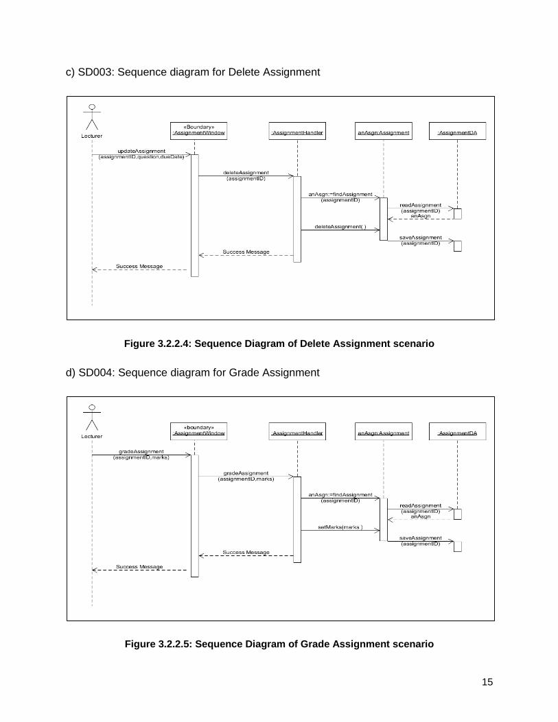
c) SD003: Sequence diagram for Delete Assignment
Figure 3.2.2.4: Sequence Diagram of Delete Assignment scenario
d) SD004: Sequence diagram for Grade Assignment
Figure 3.2.2.5: Sequence Diagram of Grade Assignment scenario
16
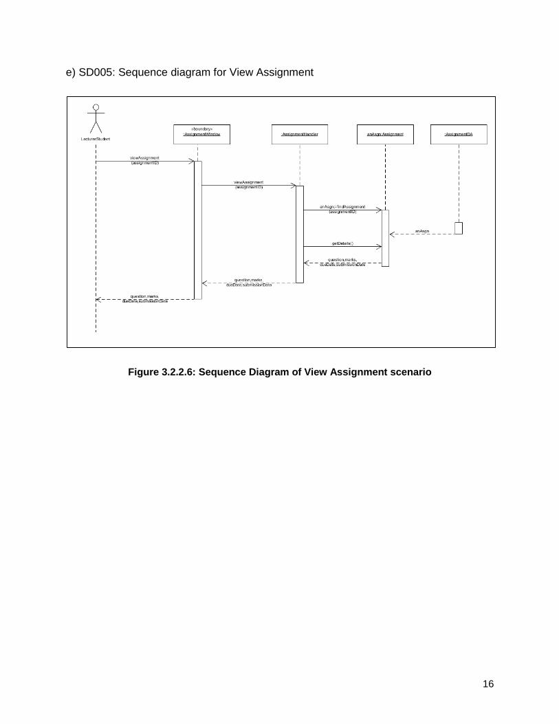
e) SD005: Sequence diagram for View Assignment
Figure 3.2.2.6: Sequence Diagram of View Assignment scenario
17
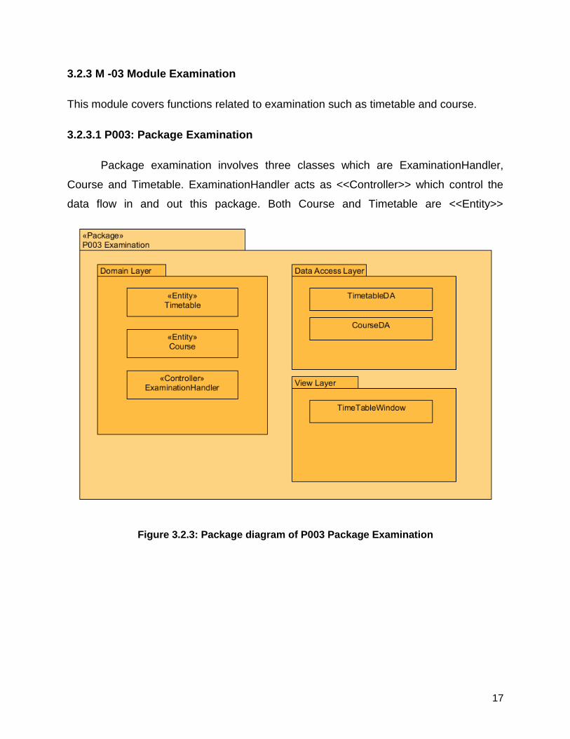
3.2.3 M -03 Module Examination
This module covers functions related to examination such as timetable and course.
3.2.3.1 P003: Package Examination
Package examination involves three classes which are ExaminationHandler,
Course and Timetable. ExaminationHandler acts as <<Controller>> which control the
data flow in and out this package. Both Course and Timetable are <<Entity>>
Figure 3.2.3: Package diagram of P003 Package Examination
18
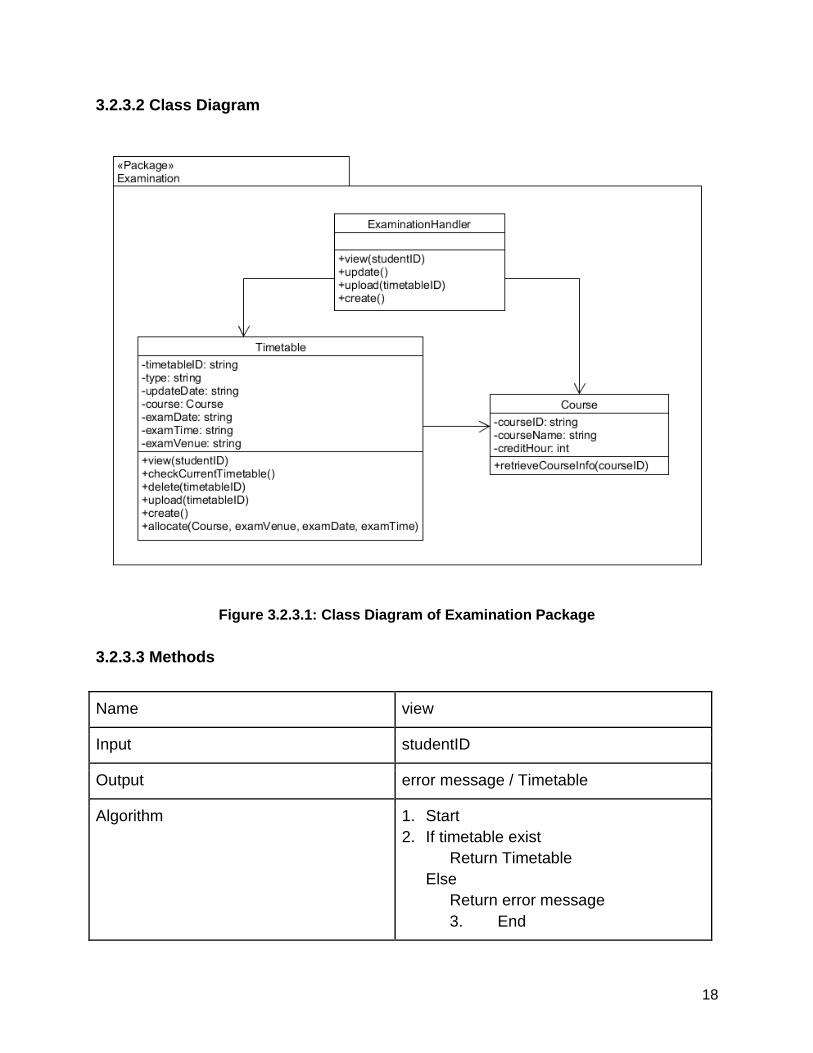
3.2.3.2 Class Diagram
Figure 3.2.3.1: Class Diagram of Examination Package
3.2.3.3 Methods
Name view
Input studentID
Output error message / Timetable
Algorithm 1. Start
2. If timetable exist
Return Timetable
Else
Return error message
3. End
19
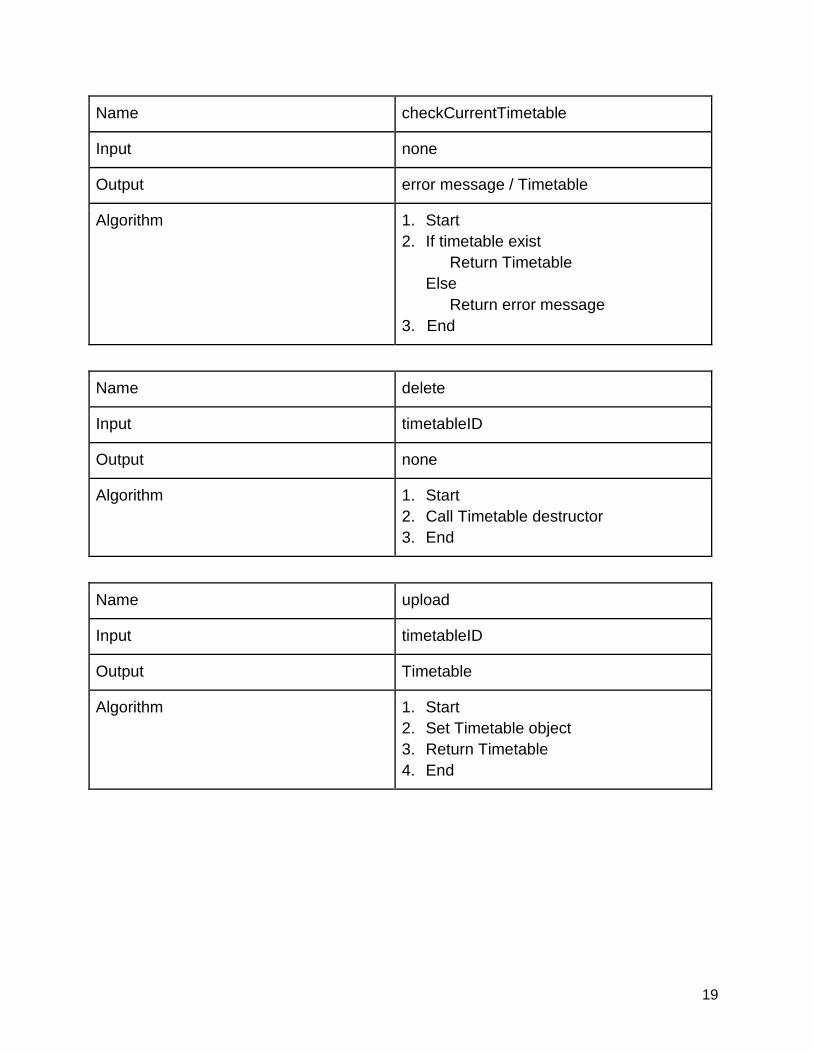
Name checkCurrentTimetable
Input none
Output error message / Timetable
Algorithm 1. Start
2. If timetable exist
Return Timetable
Else
Return error message
3. End
Name delete
Input timetableID
Output none
Algorithm 1. Start
2. Call Timetable destructor
3. End
Name upload
Input timetableID
Output Timetable
Algorithm 1. Start
2. Set Timetable object
3. Return Timetable
4. End
20
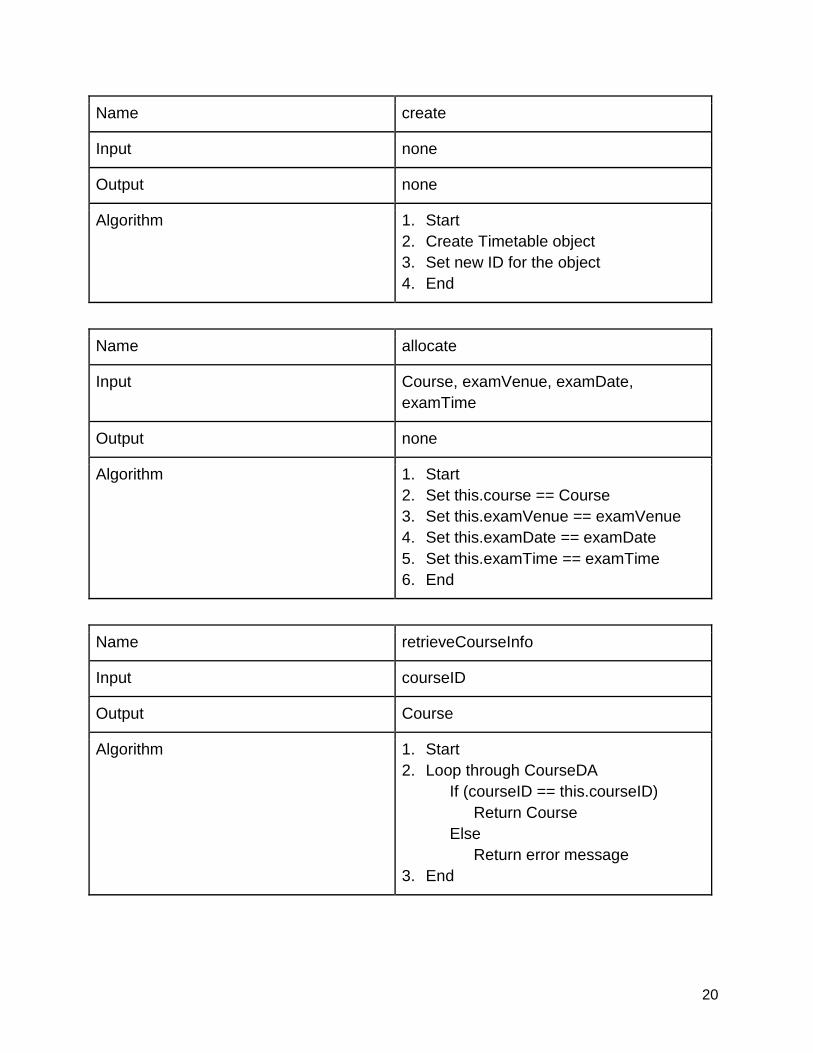
Name create
Input none
Output none
Algorithm 1. Start
2. Create Timetable object
3. Set new ID for the object
4. End
Name allocate
Input Course, examVenue, examDate,
examTime
Output none
Algorithm 1. Start
2. Set this.course == Course
3. Set this.examVenue == examVenue
4. Set this.examDate == examDate
5. Set this.examTime == examTime
6. End
Name retrieveCourseInfo
Input courseID
Output Course
Algorithm 1. Start
2. Loop through CourseDA
If (courseID == this.courseID)
Return Course
Else
Return error message
3. End
21
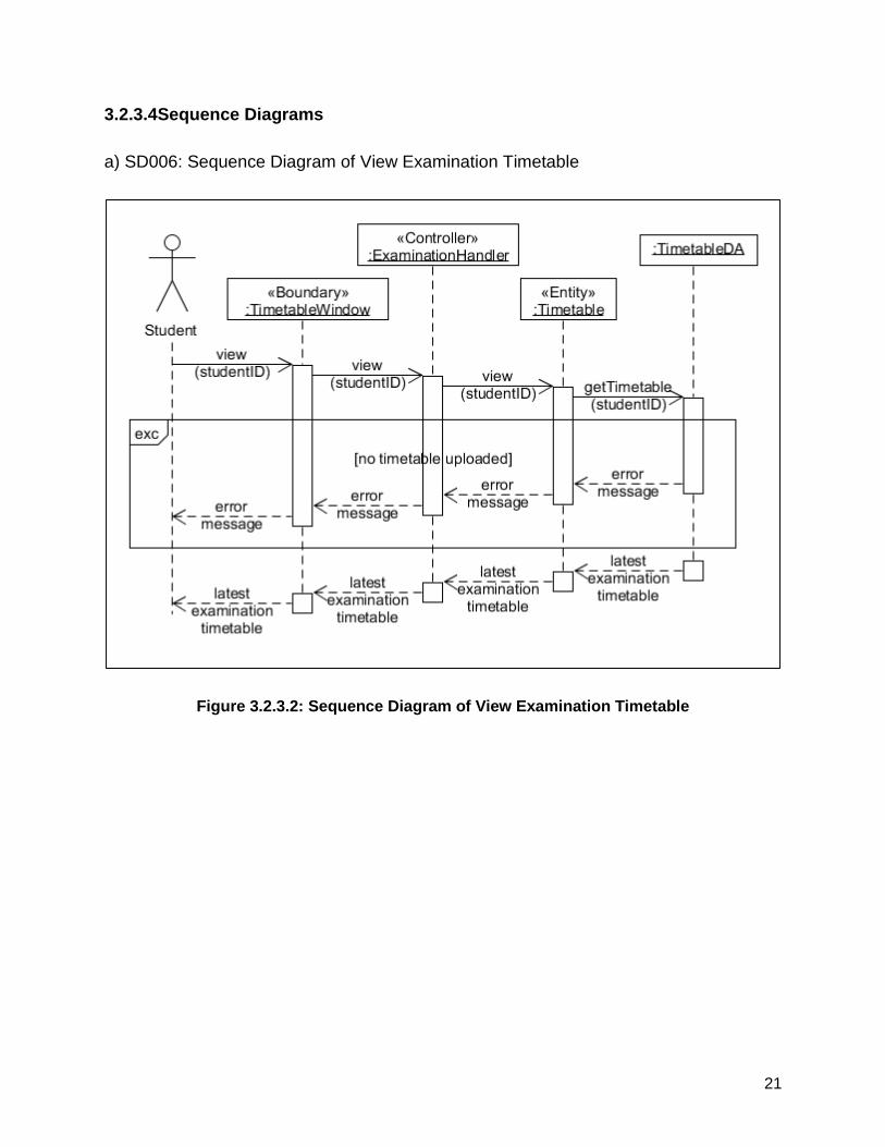
3.2.3.4Sequence Diagrams
a) SD006: Sequence Diagram of View Examination Timetable
Figure 3.2.3.2: Sequence Diagram of View Examination Timetable
22
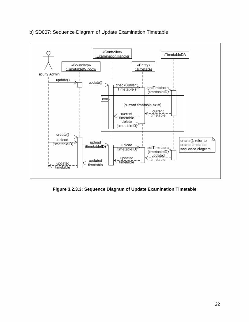
b) SD007: Sequence Diagram of Update Examination Timetable
Figure 3.2.3.3: Sequence Diagram of Update Examination Timetable
23
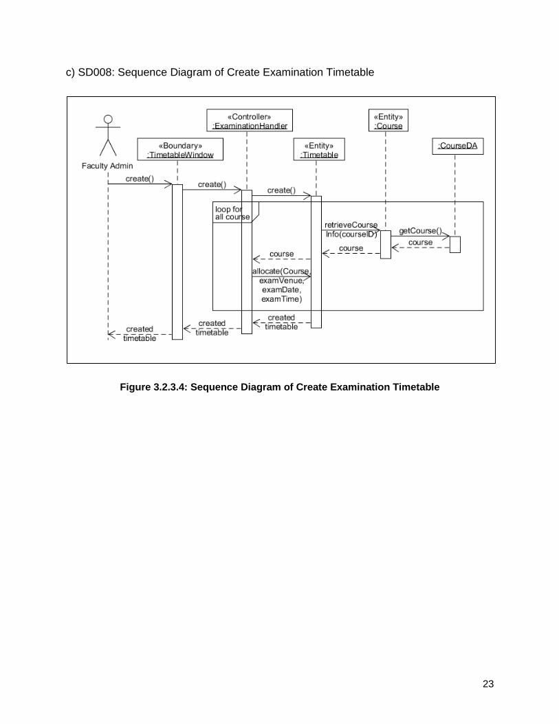
c) SD008: Sequence Diagram of Create Examination Timetable
Figure 3.2.3.4: Sequence Diagram of Create Examination Timetable
24
3.2.4 M – 04: Module Green
This module covers function that has to do with green info and green activity.
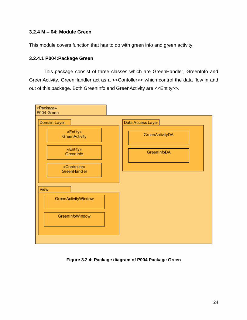
3.2.4.1 P004:Package Green
This package consist of three classes which are GreenHandler, GreenInfo and
GreenActivity. GreenHandler act as a <<Contoller>> which control the data flow in and
out of this package. Both GreenInfo and GreenActivity are <<Entity>>.
Figure 3.2.4: Package diagram of P004 Package Green
25
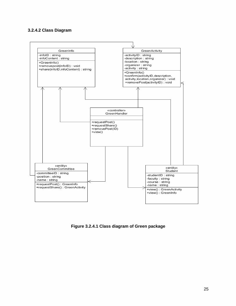
3.2.4.2 Class Diagram
Figure 3.2.4.1 Class diagram of Green package
26
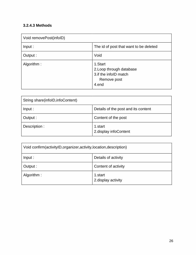
3.2.4.3 Methods
Void removePost(infoID)
Input : The id of post that want to be deleted
Output : Void
Algorithm : 1.Start
2.Loop through database
3.if the infoID match
Remove post
4.end
String share(infoID,infoContent)
Input : Details of the post and its content
Output : Content of the post
Description : 1.start
2.display infoContent
Void confirm(activityID,organizer,activity,location,description)
Input : Details of activity
Output : Content of activity
Algorithm : 1.start
2.display activity
27
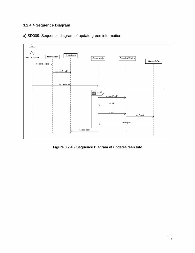
3.2.4.4 Sequence Diagram
a) SD009: Sequence diagram of update green information
Figure 3.2.4.2 Sequence Diagram of updateGreen Info
28
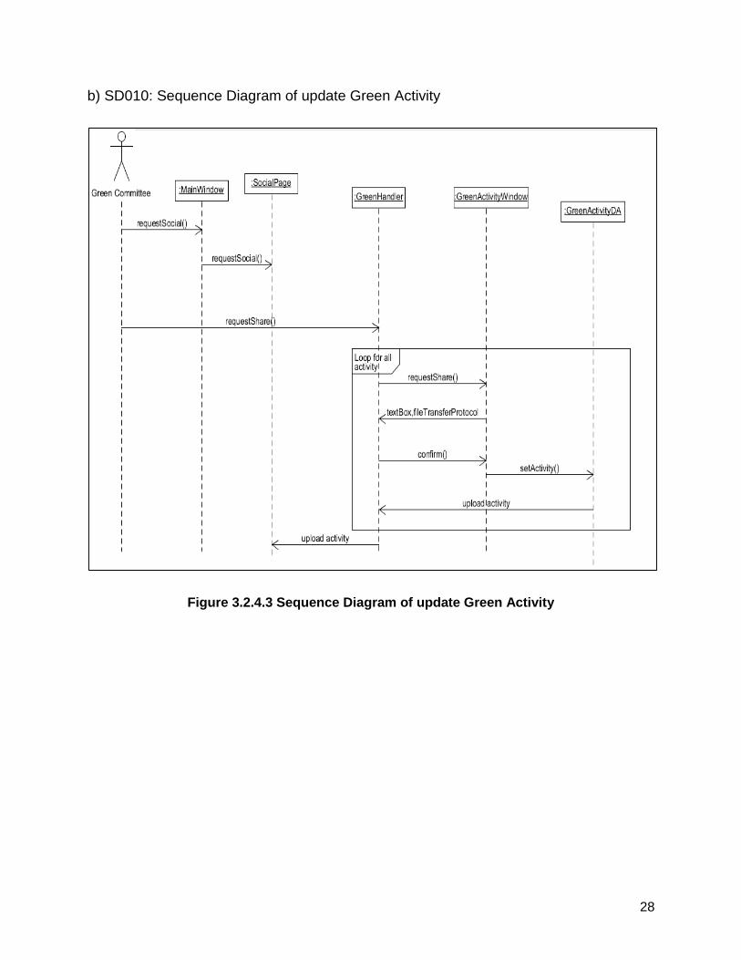
b) SD010: Sequence Diagram of update Green Activity
Figure 3.2.4.3 Sequence Diagram of update Green Activity
29
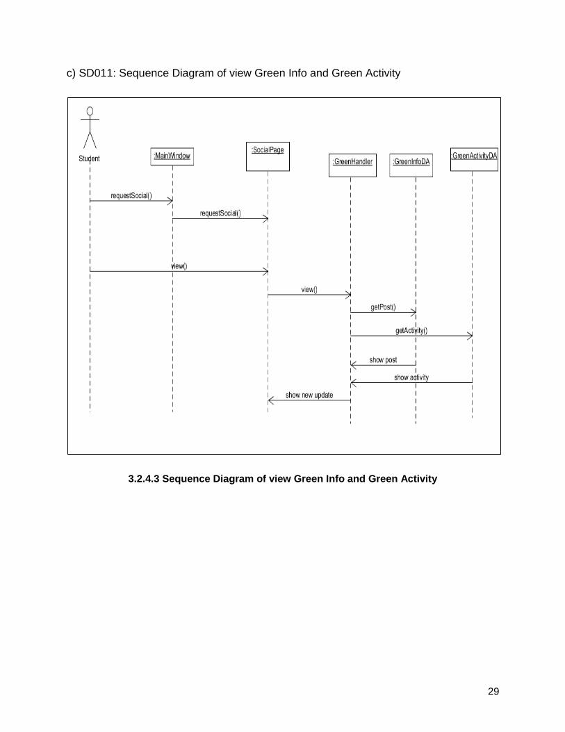
c) SD011: Sequence Diagram of view Green Info and Green Activity
3.2.4.3 Sequence Diagram of view Green Info and Green Activity
30
4. Data Design
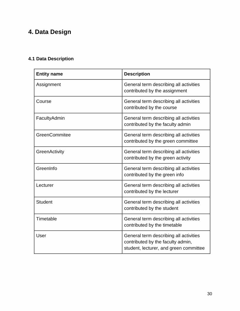
4.1 Data Description
Entity name Description
Assignment General term describing all activities
contributed by the assignment
Course General term describing all activities
contributed by the course
FacultyAdmin General term describing all activities
contributed by the faculty admin
GreenCommitee General term describing all activities
contributed by the green committee
GreenActivity General term describing all activities
contributed by the green activity
GreenInfo General term describing all activities
contributed by the green info
Lecturer General term describing all activities
contributed by the lecturer
Student General term describing all activities
contributed by the student
Timetable General term describing all activities
contributed by the timetable
User General term describing all activities
contributed by the faculty admin,
student, lecturer, and green committee
31
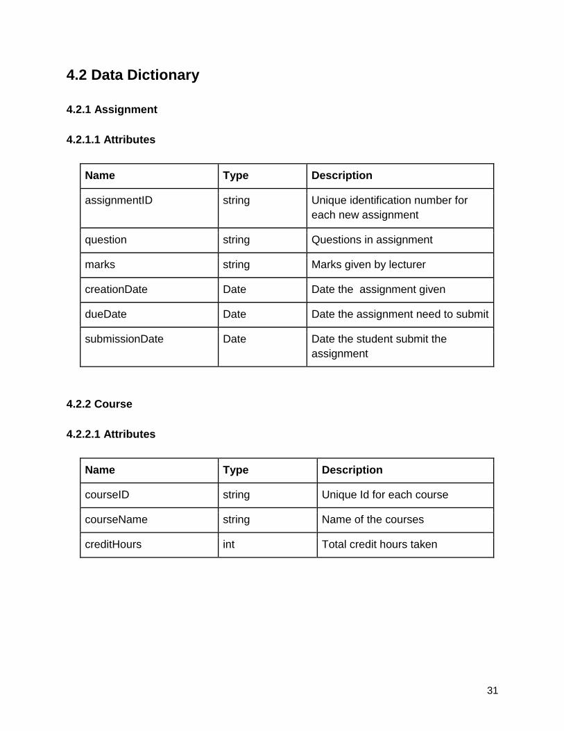
4.2 Data Dictionary
4.2.1 Assignment
4.2.1.1 Attributes
Name Type Description
assignmentID string Unique identification number for
each new assignment
question string Questions in assignment
marks string Marks given by lecturer
creationDate Date Date the assignment given
dueDate Date Date the assignment need to submit
submissionDate Date Date the student submit the
assignment
4.2.2 Course
4.2.2.1 Attributes
Name Type Description
courseID string Unique Id for each course
courseName string Name of the courses
creditHours int Total credit hours taken
32
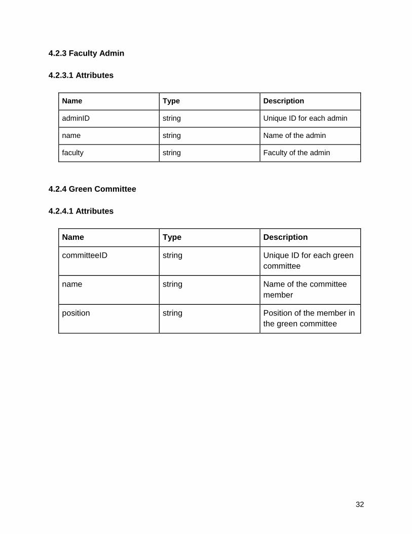
4.2.3 Faculty Admin
4.2.3.1 Attributes
Name Type Description
adminID string Unique ID for each admin
name string Name of the admin
faculty string Faculty of the admin
4.2.4 Green Committee
4.2.4.1 Attributes
Name Type Description
committeeID string Unique ID for each green
committee
name string Name of the committee
member
position string Position of the member in
the green committee
33
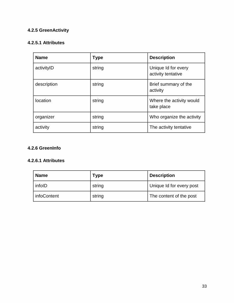
4.2.5 GreenActivity
4.2.5.1 Attributes
Name Type Description
activityID string Unique Id for every
activity tentative
description string Brief summary of the
activity
location string Where the activity would
take place
organizer string Who organize the activity
activity string The activity tentative
4.2.6 GreenInfo
4.2.6.1 Attributes
Name Type Description
infoID string Unique Id for every post
infoContent string The content of the post
34
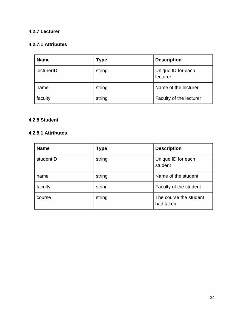
4.2.7 Lecturer
4.2.7.1 Attributes
Name Type Description
lecturerID string Unique ID for each
lecturer
name string Name of the lecturer
faculty string Faculty of the lecturer
4.2.8 Student
4.2.8.1 Attributes
Name Type Description
studentID string Unique ID for each
student
name string Name of the student
faculty string Faculty of the student
course string The course the student
had taken
35
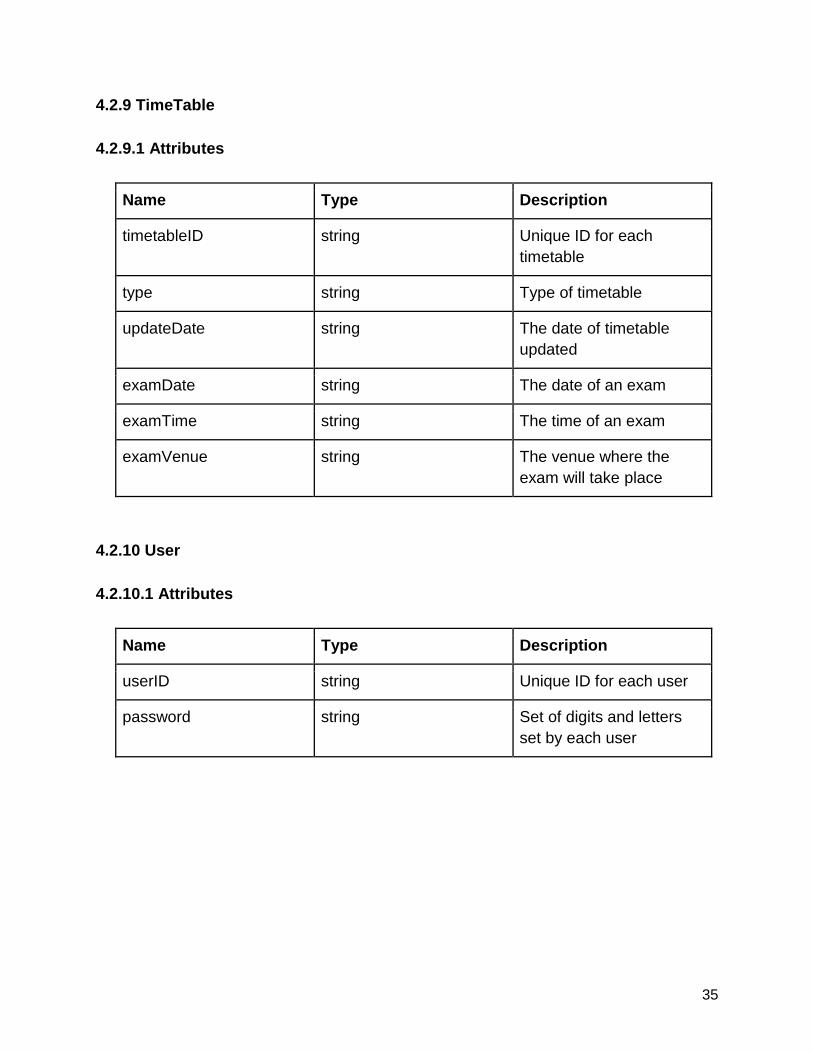
4.2.9 TimeTable
4.2.9.1 Attributes
Name Type Description
timetableID string Unique ID for each
timetable
type string Type of timetable
updateDate string The date of timetable
updated
examDate string The date of an exam
examTime string The time of an exam
examVenue string The venue where the
exam will take place
4.2.10 User
4.2.10.1 Attributes
Name Type Description
userID string Unique ID for each user
password string Set of digits and letters
set by each user
36
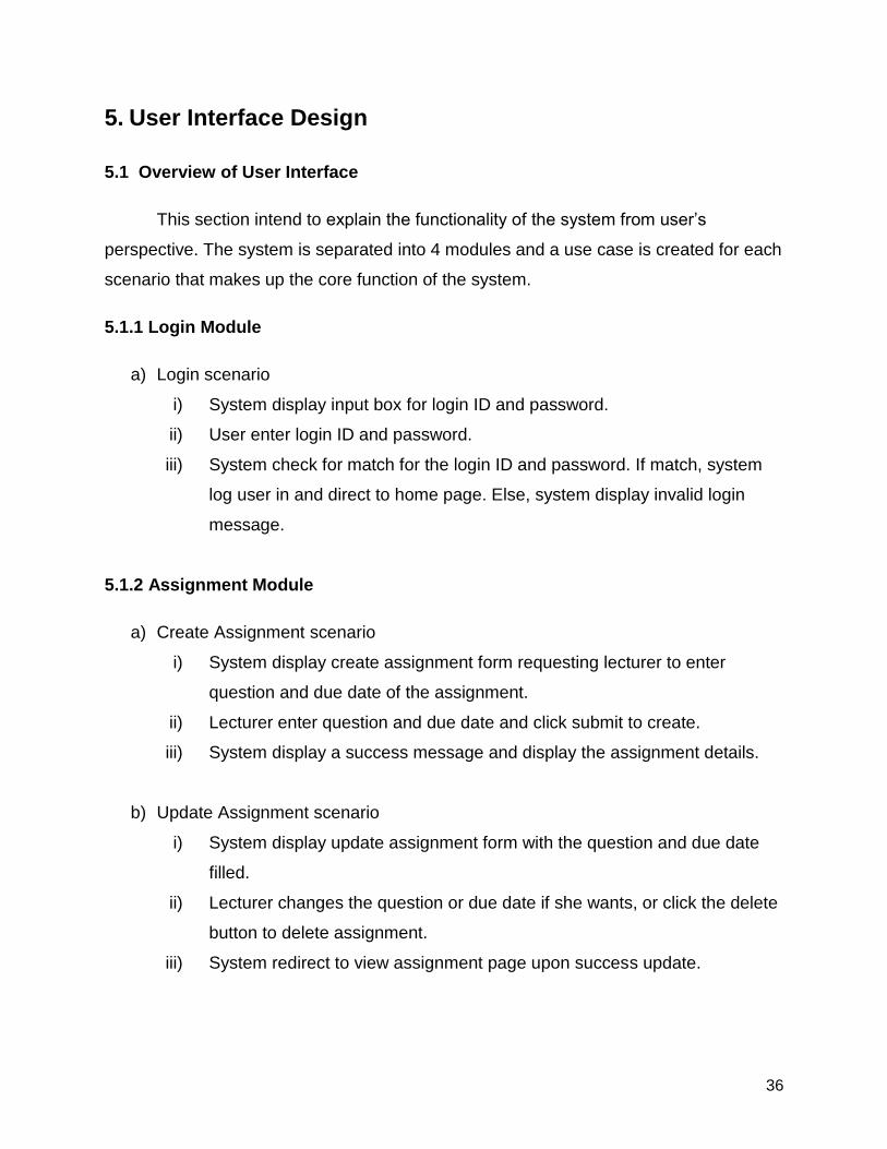
5. User Interface Design
5.1 Overview of User Interface
This section intend to explain the functionality of the system from user’s
perspective. The system is separated into 4 modules and a use case is created for each
scenario that makes up the core function of the system.
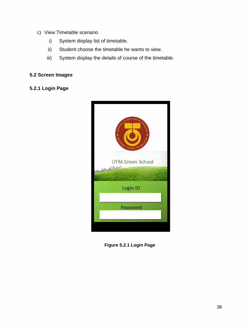
5.1.1 Login Module
a) Login scenario
i) System display input box for login ID and password.
ii) User enter login ID and password.
iii) System check for match for the login ID and password. If match, system
log user in and direct to home page. Else, system display invalid login
message.
5.1.2 Assignment Module
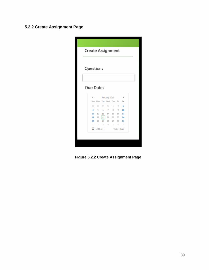
a) Create Assignment scenario
i) System display create assignment form requesting lecturer to enter
question and due date of the assignment.
ii) Lecturer enter question and due date and click submit to create.
iii) System display a success message and display the assignment details.
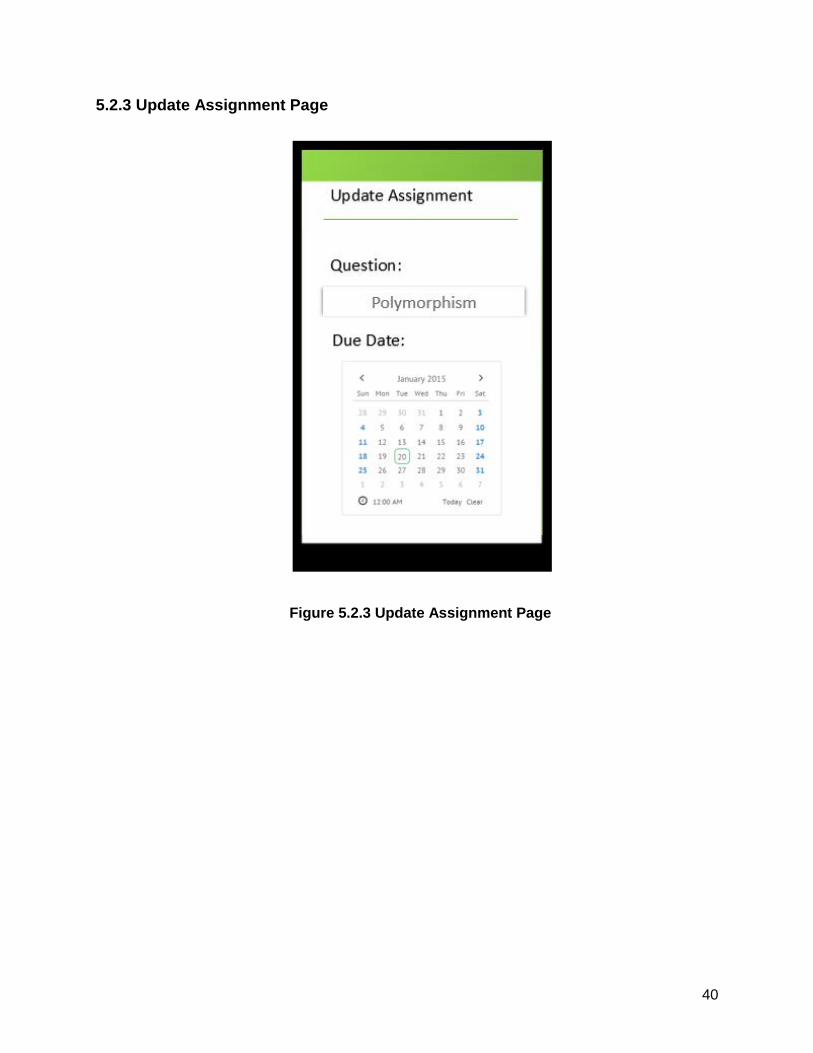
b) Update Assignment scenario
i) System display update assignment form with the question and due date
filled.
ii) Lecturer changes the question or due date if she wants, or click the delete
button to delete assignment.
iii) System redirect to view assignment page upon success update.
37
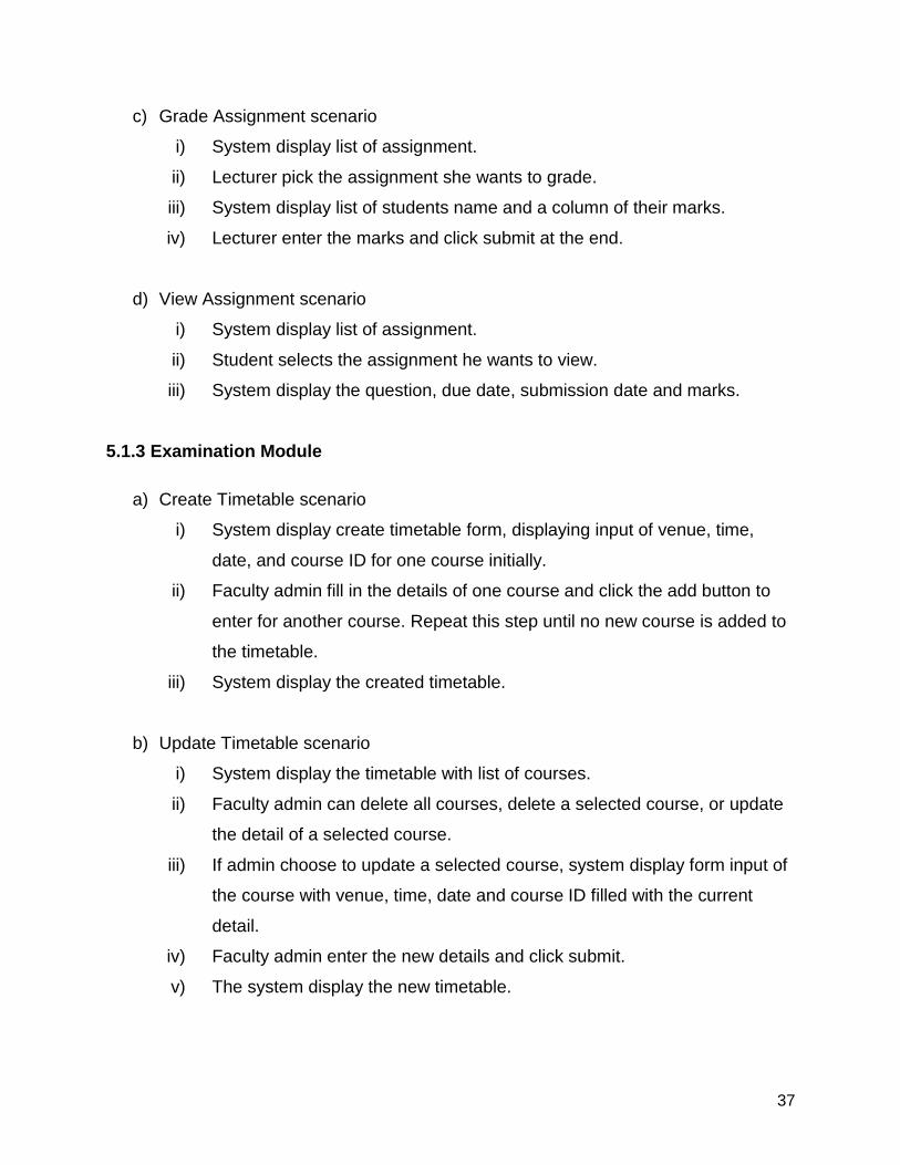
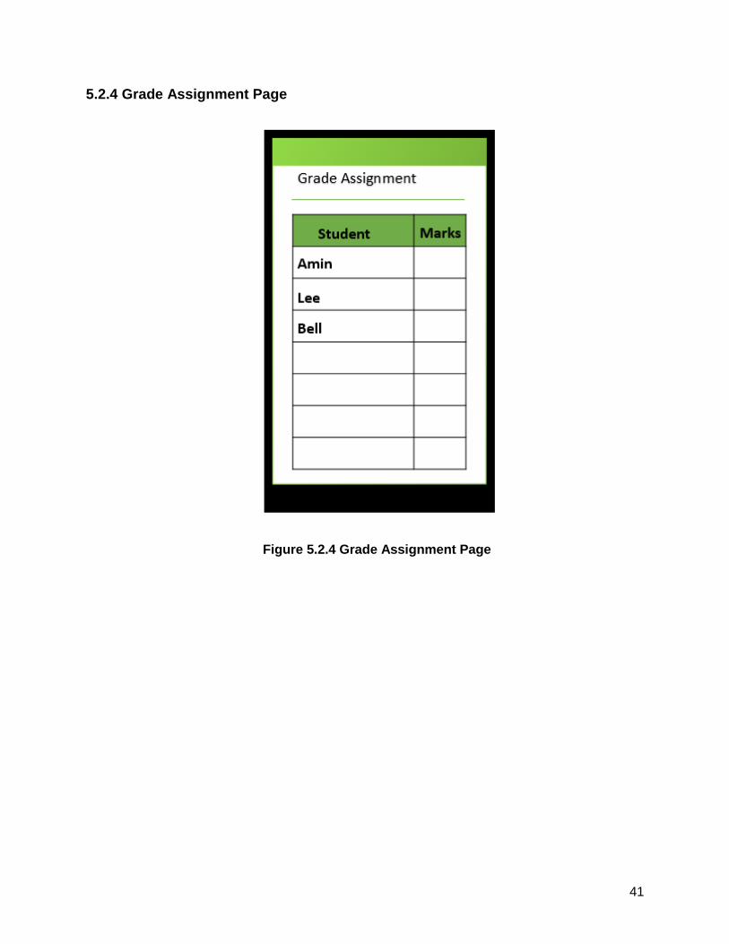
c) Grade Assignment scenario
i) System display list of assignment.
ii) Lecturer pick the assignment she wants to grade.
iii) System display list of students name and a column of their marks.
iv) Lecturer enter the marks and click submit at the end.
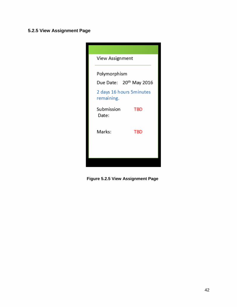
d) View Assignment scenario
i) System display list of assignment.
ii) Student selects the assignment he wants to view.
iii) System display the question, due date, submission date and marks.
5.1.3 Examination Module
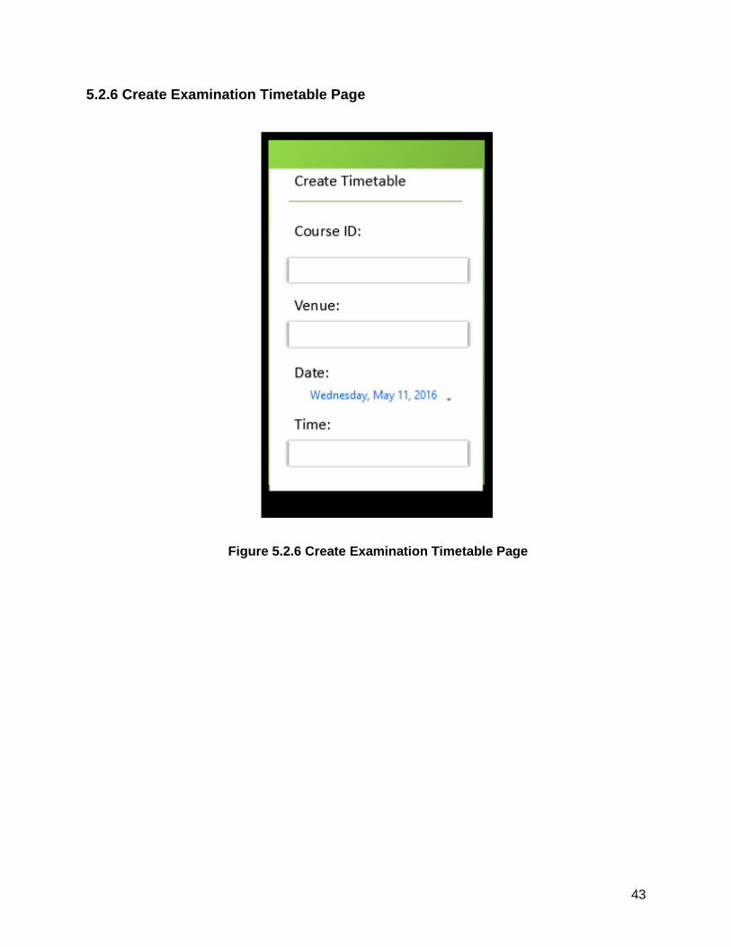
a) Create Timetable scenario
i) System display create timetable form, displaying input of venue, time,
date, and course ID for one course initially.
ii) Faculty admin fill in the details of one course and click the add button to
enter for another course. Repeat this step until no new course is added to
the timetable.
iii) System display the created timetable.
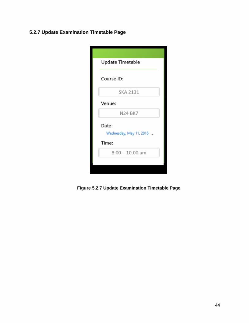
b) Update Timetable scenario
i) System display the timetable with list of courses.
ii) Faculty admin can delete all courses, delete a selected course, or update
the detail of a selected course.
iii) If admin choose to update a selected course, system display form input of
the course with venue, time, date and course ID filled with the current
detail.
iv) Faculty admin enter the new details and click submit.
v) The system display the new timetable.
38
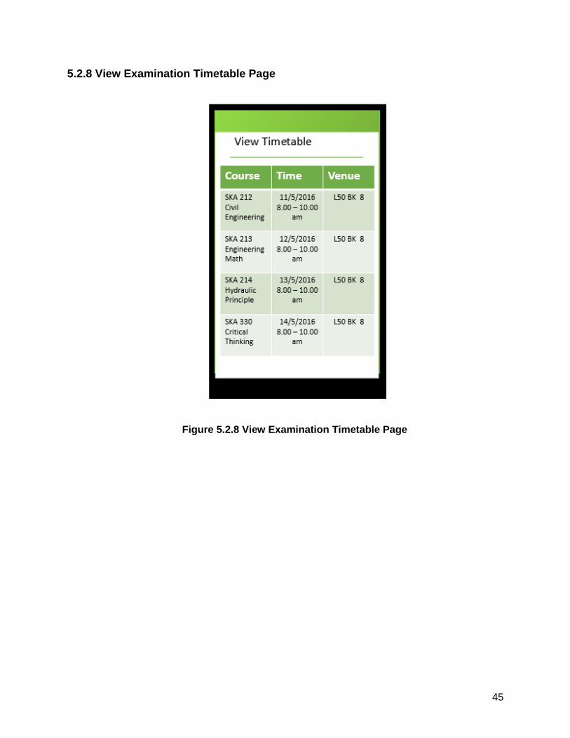
c) View Timetable scenario
i) System display list of timetable.
ii) Student choose the timetable he wants to view.
iii) System display the details of course of the timetable.
5.2 Screen Images
5.2.1 Login Page
Figure 5.2.1 Login Page
39
5.2.2 Create Assignment Page
Figure 5.2.2 Create Assignment Page
40
5.2.3 Update Assignment Page
Figure 5.2.3 Update Assignment Page
41
5.2.4 Grade Assignment Page
Figure 5.2.4 Grade Assignment Page
42
5.2.5 View Assignment Page
Figure 5.2.5 View Assignment Page
43
5.2.6 Create Examination Timetable Page
Figure 5.2.6 Create Examination Timetable Page
44
5.2.7 Update Examination Timetable Page
Figure 5.2.7 Update Examination Timetable Page
45
5.2.8 View Examination Timetable Page
Figure 5.2.8 View Examination Timetable Page
46
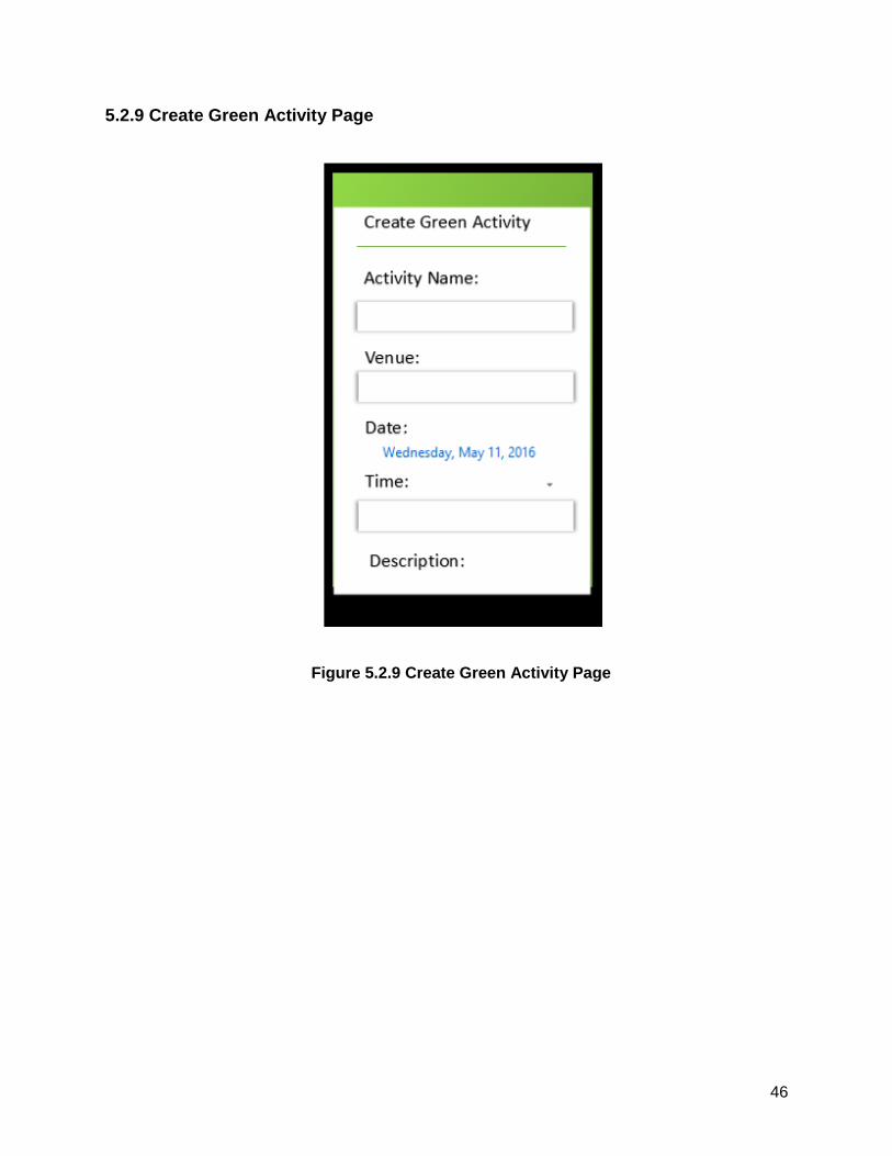
5.2.9 Create Green Activity Page
Figure 5.2.9 Create Green Activity Page
47
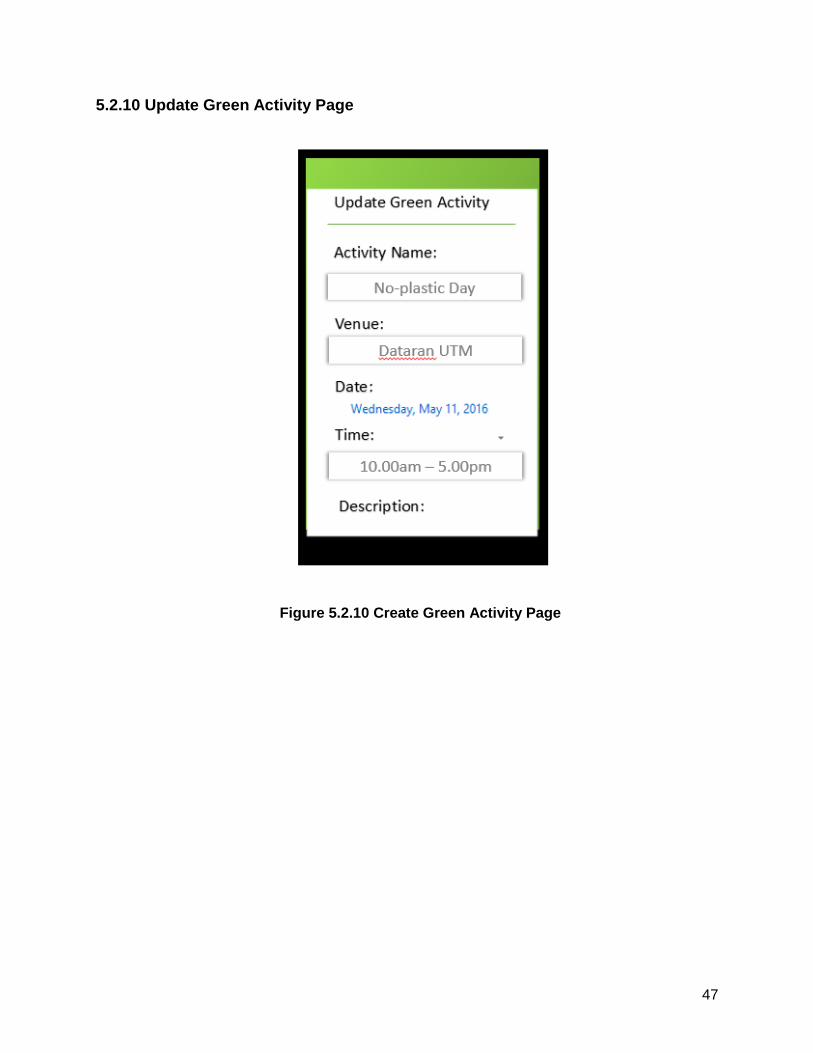
5.2.10 Update Green Activity Page
Figure 5.2.10 Create Green Activity Page
48
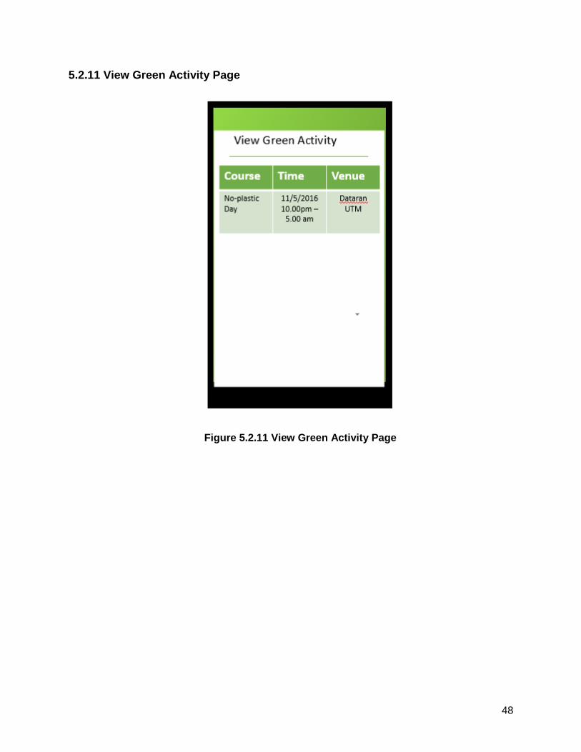
5.2.11 View Green Activity Page
Figure 5.2.11 View Green Activity Page
49
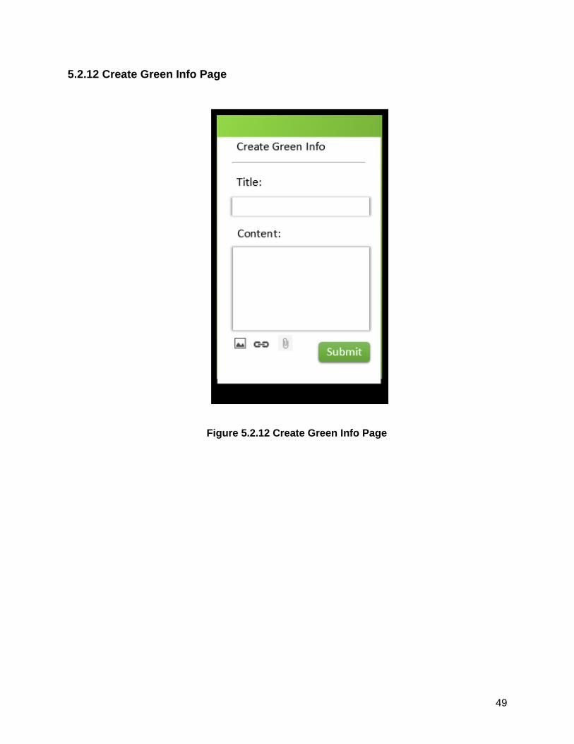
5.2.12 Create Green Info Page
Figure 5.2.12 Create Green Info Page
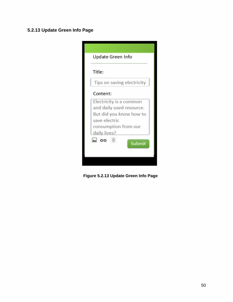
50
5.2.13 Update Green Info Page
Figure 5.2.13 Update Green Info Page
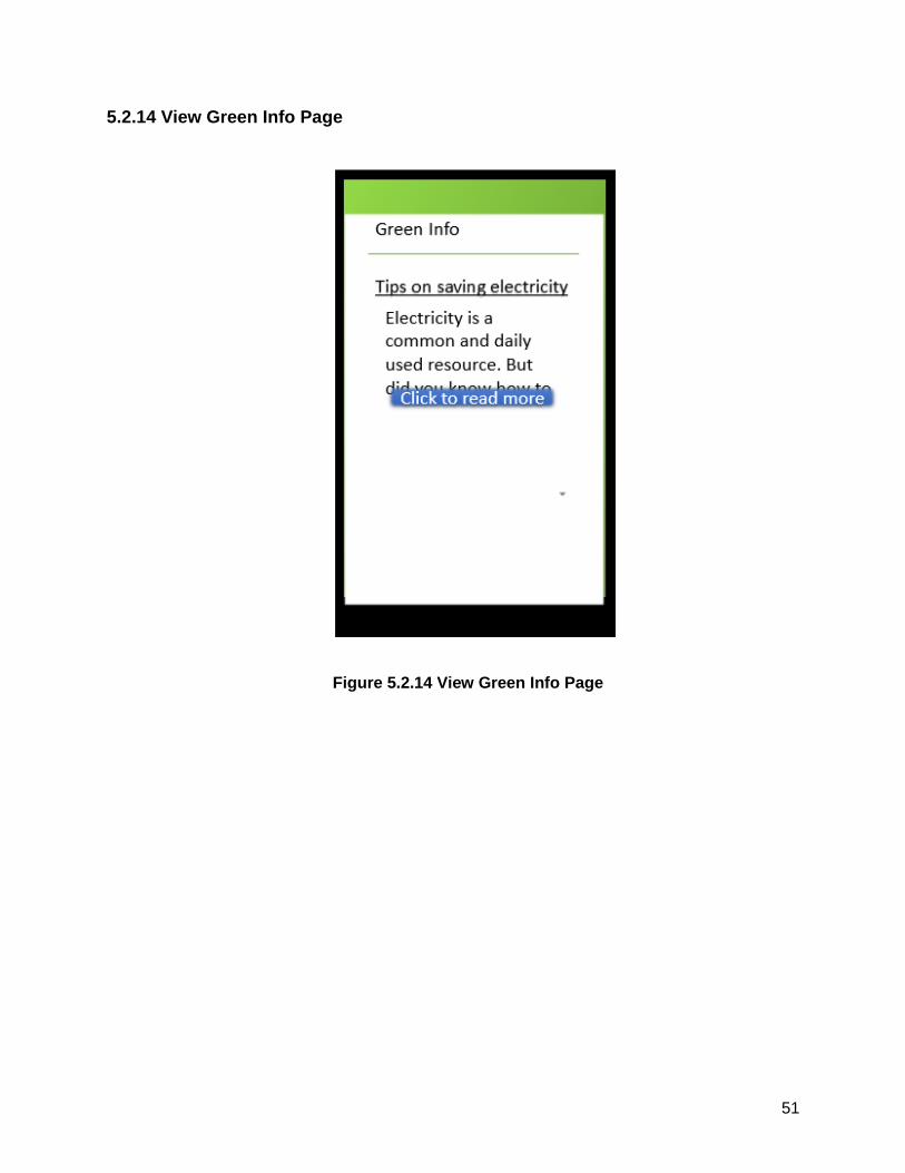
51
5.2.14 View Green Info Page
Figure 5.2.14 View Green Info Page
52
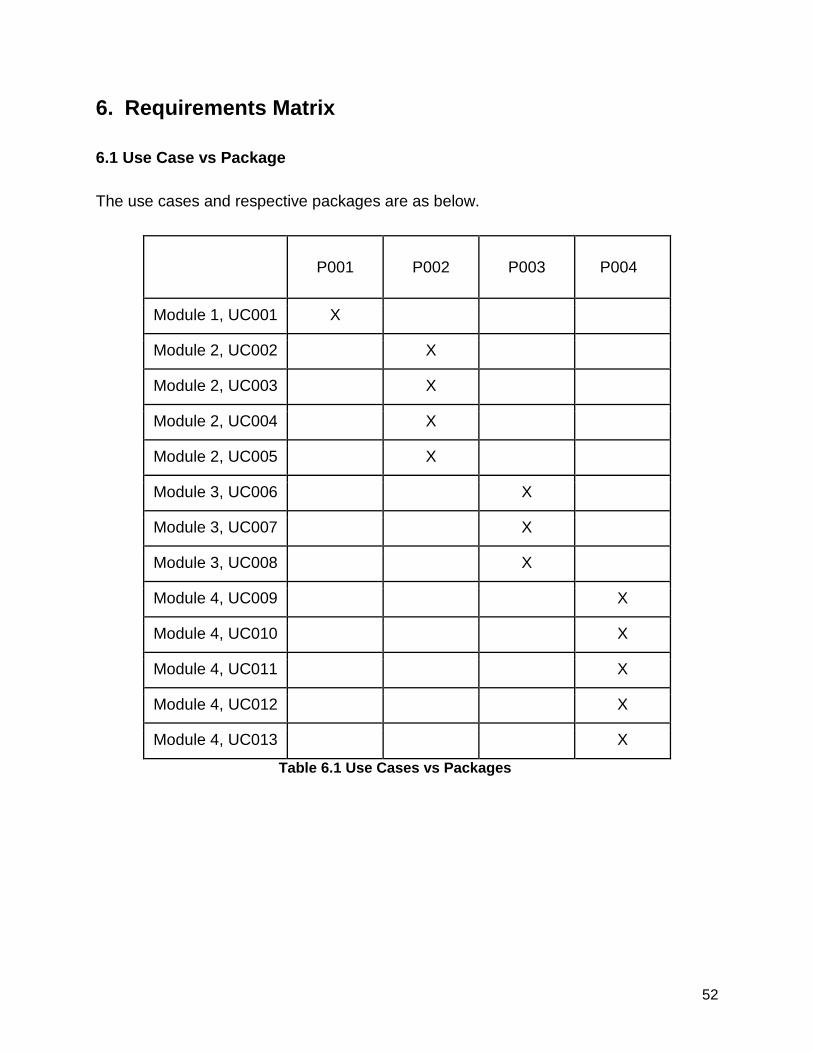
6. Requirements Matrix
6.1 Use Case vs Package
The use cases and respective packages are as below.
P001 P002 P003 P004
Module 1, UC001 X
Module 2, UC002 X
Module 2, UC003 X
Module 2, UC004 X
Module 2, UC005 X
Module 3, UC006 X
Module 3, UC007 X
Module 3, UC008 X
Module 4, UC009 X
Module 4, UC010 X
Module 4, UC011 X
Module 4, UC012 X
Module 4, UC013 X
Table 6.1 Use Cases vs Packages
53
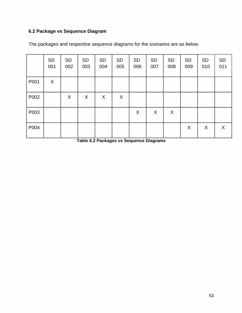
6.2 Package vs Sequence Diagram
The packages and respective sequence diagrams for the scenarios are as below.
SD
001
SD
002
SD
003
SD
004
SD
005
SD
006
SD
007
SD
008
SD
009
SD
010
SD
011
P001 X
P002 X X X X
P003 X X X
P004 X X X
Table 6.2 Packages vs Sequence Diagrams
54
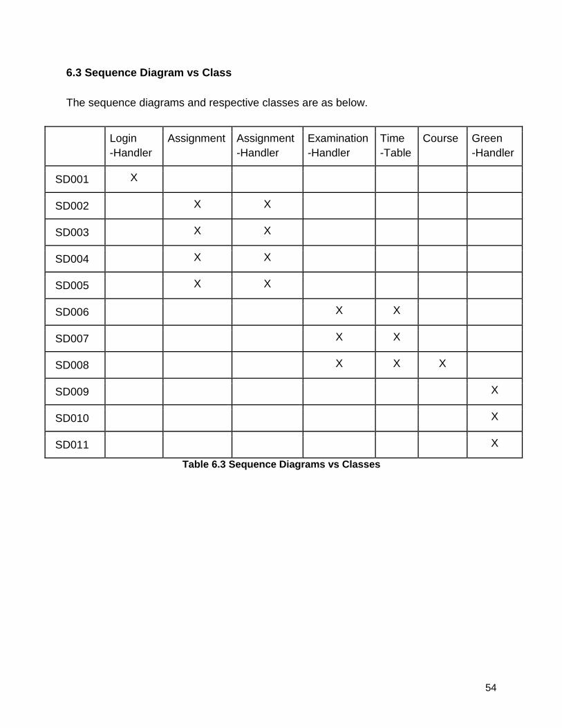
6.3 Sequence Diagram vs Class
The sequence diagrams and respective classes are as below.
Login
-Handler
Assignment Assignment
-Handler
Examination
-Handler
Time
-Table
Course Green
-Handler
SD001 X
SD002 X X
SD003 X X
SD004 X X
SD005 X X
SD006 X X
SD007 X X
SD008 X X X
SD009 X
SD010 X
SD011 X
Table 6.3 Sequence Diagrams vs Classes