Embed Size (px)
Citation preview
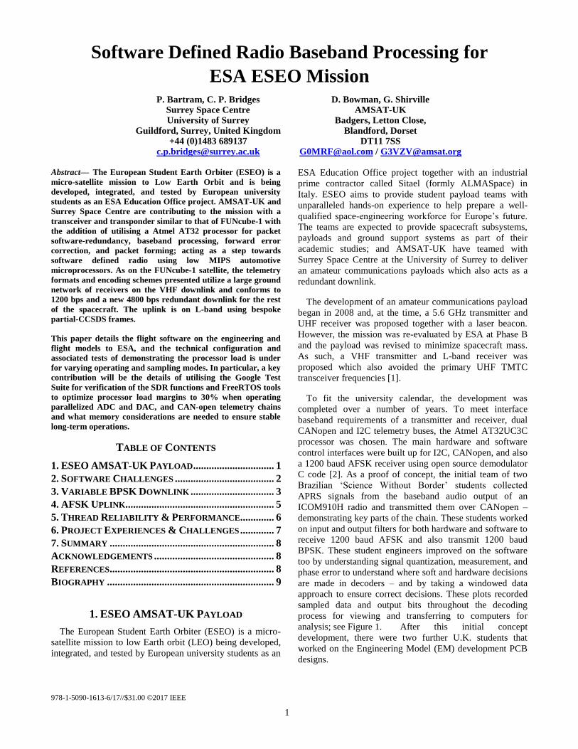
978-1-5090-1613-6/17//$31.00 ©2017 IEEE
1
Software Defined Radio Baseband Processing for
ESA ESEO Mission P. Bartram, C. P. Bridges
Surrey Space Centre University of Surrey
Guildford, Surrey, United Kingdom +44 (0)1483 689137
D. Bowman, G. Shirville AMSAT-UK
Badgers, Letton Close, Blandford, Dorset
DT11 7SS [email protected] / [email protected]
Abstract— The European Student Earth Orbiter (ESEO) is a
micro-satellite mission to Low Earth Orbit and is being
developed, integrated, and tested by European university
students as an ESA Education Office project. AMSAT-UK and
Surrey Space Centre are contributing to the mission with a
transceiver and transponder similar to that of FUNcube-1 with
the addition of utilising a Atmel AT32 processor for packet
software-redundancy, baseband processing, forward error
correction, and packet forming; acting as a step towards
software defined radio using low MIPS automotive
microprocessors. As on the FUNcube-1 satellite, the telemetry
formats and encoding schemes presented utilize a large ground
network of receivers on the VHF downlink and conforms to
1200 bps and a new 4800 bps redundant downlink for the rest
of the spacecraft. The uplink is on L-band using bespoke
partial-CCSDS frames.
This paper details the flight software on the engineering and
flight models to ESA, and the technical configuration and
associated tests of demonstrating the processor load is under
for varying operating and sampling modes. In particular, a key
contribution will be the details of utilising the Google Test
Suite for verification of the SDR functions and FreeRTOS tools
to optimize processor load margins to 30% when operating
parallelized ADC and DAC, and CAN-open telemetry chains
and what memory considerations are needed to ensure stable
long-term operations.
TABLE OF CONTENTS
1. ESEO AMSAT-UK PAYLOAD ............................... 1 2. SOFTWARE CHALLENGES ...................................... 2 3. VARIABLE BPSK DOWNLINK ................................ 3 4. AFSK UPLINK......................................................... 5 5. THREAD RELIABILITY & PERFORMANCE............. 6 6. PROJECT EXPERIENCES & CHALLENGES ............. 7 7. SUMMARY ............................................................... 8 ACKNOWLEDGEMENTS .............................................. 8 REFERENCES............................................................... 8 BIOGRAPHY ................................................................ 9
1. ESEO AMSAT-UK PAYLOAD
The European Student Earth Orbiter (ESEO) is a micro-
satellite mission to low Earth orbit (LEO) being developed,
integrated, and tested by European university students as an
ESA Education Office project together with an industrial
prime contractor called Sitael (formly ALMASpace) in
Italy. ESEO aims to provide student payload teams with
unparalleled hands-on experience to help prepare a well-
qualified space-engineering workforce for Europe’s future.
The teams are expected to provide spacecraft subsystems,
payloads and ground support systems as part of their
academic studies; and AMSAT-UK have teamed with
Surrey Space Centre at the University of Surrey to deliver
an amateur communications payloads which also acts as a
redundant downlink.
The development of an amateur communications payload
began in 2008 and, at the time, a 5.6 GHz transmitter and
UHF receiver was proposed together with a laser beacon.
However, the mission was re-evaluated by ESA at Phase B
and the payload was revised to minimize spacecraft mass.
As such, a VHF transmitter and L-band receiver was
proposed which also avoided the primary UHF TMTC
transceiver frequencies [1].
To fit the university calendar, the development was
completed over a number of years. To meet interface
baseband requirements of a transmitter and receiver, dual
CANopen and I2C telemetry buses, the Atmel AT32UC3C
processor was chosen. The main hardware and software
control interfaces were built up for I2C, CANopen, and also
a 1200 baud AFSK receiver using open source demodulator
C code [2]. As a proof of concept, the initial team of two
Brazilian ‘Science Without Border’ students collected
APRS signals from the baseband audio output of an
ICOM910H radio and transmitted them over CANopen –
demonstrating key parts of the chain. These students worked
on input and output filters for both hardware and software to
receive 1200 baud AFSK and also transmit 1200 baud
BPSK. These student engineers improved on the software
too by understanding signal quantization, measurement, and
phase error to understand where soft and hardware decisions
are made in decoders – and by taking a windowed data
approach to ensure correct decisions. These plots recorded
sampled data and output bits throughout the decoding
process for viewing and transferring to computers for
analysis; see Figure 1. After this initial concept
development, there were two further U.K. students that
worked on the Engineering Model (EM) development PCB
designs.

2
The EM is broken into three boards: a computing and
electrical power board, an L-band receiver, and a VHF
transmitter; see Figure 2.
Figure 2: AMSAT Payload during firmware
programming prior to testing
Figure 3: EM during integration & test at the Sitael Lab
Facilities in October 2016 at Forli, Italy (see top-right)
The unit locates the two RF boards underneath the
computing and electrical power board which is visible in
Figure 2. The external interfaces are dual CAN interfaces,
one power connector, two SMA antenna connectors, and
one JTAG connector for debugging and programming. In
addition to these students, a U.K. MSc student who realized
the flight software was involved is the primary focus of this
paper. In the future, a German student will aid in the FM
unit build and environmental test, qualification, and
acceptance.
2. SOFTWARE CHALLENGES
A key finding of the literature reviewed for this project
was that in order to meet ESA timing and resource
management constraints [3], it would be necessary to utilize
a real time operating system (RTOS). Due to its small
memory footprint and processor cycle overhead, combined
with its free license, FreeRTOS was selected for use. This
allowed for functional areas of the software to be split up
into threads, thereby isolating discrete software functionality
and allowing for best practice development techniques to be
used. Therefore CANopen, uplink, downlink, telemetry
collection, payload data transfer and satellite operations
were split into individual threads.
A problem encountered due to the multi-organizational
nature of this project was that of developing software to a
strictly defined interface between organizations and proving
the functionality before the two systems were coupled. An
example of this was the application layer protocols
operating on top of the CANopen communications protocol,
allowing for communications between the AMSAT payload
and satellite itself. An emulator with limited functionality
was supplied by ALMAspace to ensure correct hardware
configuration however this would not prove higher level
software operations, as a trial a software development
practice entitled Test Driven Development (TDD) was used
throughout the project, the end result of this was that when
the payload was integrated with the satellite it worked
immediately – the value of TDD has been seen many times
over during this development and should be strongly
considered by anyone wishing to collaborate on a project
successfully.
A key consideration for the development of this payload
was the embedded processor memory and processing
constraints. The microcontroller was specifically selected to
Figure 1: a) Correlating decoder decisions with output samples, b) marking decision points, and c) windowed decision
making with phase compensation

3
have the highest amount of RAM and flash available for its
class, with 64kB and 512kB respectively. The memory map
can be seen in Figure 4 with separate regions being
allocated to program data, filter lookup tables, default
values and also to payload data. The first two of these
regions are fixed after programming whereas the final two
regions are dynamic as the mission progresses, therefore the
lower two regions were locked during programming to
ensure that a single event upset (SEU) could not cause a
write meant for the dynamic region to be redirected to
overwrite the fixed region – potentially causing catastrophic
mission failure.
Figure 4: AT32 Memory Map
SEUs are a major cause of concern for non-radiation
harderned devices and without writing a large amount of
protective code it is difficult to protect against their effects.
In addition, it is possible that the protective code can also
inadvertently introduce bugs, therefore a non-code-invasive
method of protecting against a percentage of SEUs was
desirable.
A novel method for protection was therefore trialed by
making modifications to the FreeRTOS kernel itself, and
combined the traditional protective method of triple modular
redundancy (TMR) of data with the FreeRTOS context
switching system. Thus, whenever a context switch is made
by FreeRTOS the kernel modifications ensure that no SEUs
have caused bit flips in the context stack about to be
switched in – this offers protection to all variables placed
onto the stack, and offers a protection percentage inversely
proportional to the percentage of time that a thread is
running. The overhead associated with this protection
process is clearly application specific and depends on the
amount of data placed onto the stack and also on whether
threads are preempted or not. Application specific speed
gains can be achieved through only checking variables on
the stack that are currently active. In the case of this payload
this technique offered protection against 27% - 99% of
SEUs depending on the particular thread at a processor
overhead of ~5%. SEUs detected and corrected via the use
of this technique are transmitted in the satellite telemetry
package and therefore an evaluation of the efficacy will later
be performed with on-orbit data.
3. VARIABLE BPSK DOWNLINK
The primary mission of this payload is the collection and
transmission of telemetry data to the ground. However, in
the event of failure of the primary communications system,
this payload must also act as a redundant downlink option
for transfer of scientific data from other scientific payloads.
Therefore it was necessary for the payload to be able to
transfer telemetry and scientific data reliably, without error
and at a rate that allows for scientific data to be transferred
in a ‘reasonable’ time period, reasonable was defined as
being within a typical LEO groundstation pass ~7 minutes.
Such that the payload could make use of the AMSAT
groundstation network, it was necessary to conform to the
AO-40 [4] forward error correction (FEC) standard, this was
done simply through the use of a C library – the only
functional restriction this imposed was that a packet of 256
bytes had to be used which would then grow in size to 650
bytes including forward error correction bits.
Standard downlink packets are split into two parts, a real
time telemetry (RTT) section and a whole orbit data (WOD)
section, but ultimately the sum of these two parts is 256
bytes with the RTT being sampled via the I2C sensors every
5 seconds. Therefore a data rate of 1.2 kbps allows for the
RTT to be transmitted in realtime – taking 4.3 seconds to
transmit once the FEC data is added. In contrast scientific
data transfer was not capable of being transferred at this
data rate, with a maximum payload data size of 64 kB
requiring ~18 minutes after FEC data is added. This is
longer than a typical LEO groundstation pass and was
therefore unacceptable. Thus an increased data rate of 4.8
kbps was developed to bring the transfer time to within the
desired window. Both data rates were implemented using a
BPSK modulation scheme to increase the reliability over a
lossy link and be spectrally efficient.
As the modulation scheme and two data transmission
rates were known, it was necessary to determine the rate at
which the DAC would output samples to the modulator. The
ratio of the sampling rate to the BPSK baud rate is the
number of DAC output samples representing a single
symbol, and is commonly referred to as the DAC
oversampling rate. Theoretically, it is possible to reconstruct
an identical DAC output waveform perfectly so long as the
oversampling rate is equal to the Nyquist frequency, i.e
twice the highest frequency component [5]. However,
sampling at this rate means that the closest signal harmonics
image will be present at twice the signal frequency [6] and
adds severe requirements on the roll-off of the hardware
anti-aliasing filter in order to stop transmission of these
higher frequency components. Therefore, it was decided that
oversampling would be applied to reduce the requirements

4
on this filter. Traditional systems such as CD players use an
oversampling rate of 2, 4 or 8 times the Nyquist frequency
[6], therefore this served as a starting point from which to
evaluate the performance at these rates. For software design
simplicity, a single DAC sampling rate was used for both
transmission modes. A final sampling rate of 19.2 ksps was
used, meaning the 1.2 kbps and 4.8 kbps signals were
oversampled at eight times and twice the Nyquist frequency
respectively. Another consideration was that of the trade-off
between sampling rate impact on waveform quality and the
processor cycles available to perform other operations
between samples. A sampling rate of 19.2 ksps allowed for
3125 processor operations to be performed between each
sample, allowing for data to be encoded and delivered to the
DAC at the correct time.
As an initial experiment, an unfiltered output signal was
fed into the BPSK modulator and the broadcast RF signal
observed. The frequency domain result of this can be seen in
Figure 5. It can clearly be seen that there are signal
harmonics present, with the highest harmonic amplitude
being only -15dB below the intended signal even with a
hardware low pass filter present.
Figure 5: Unfiltered BPSK modulator output
This was unacceptable and further digital signal
processing was applied to filter the output waveform. This
was done through the use of the Raised Root Cosine (RRC)
Filter and is specified through Equation 1 [7].
𝐻𝑅𝐶𝐹
=
{
𝑇, |𝑓| ≤
1 − 𝛽
2𝑇
𝑇
2 [1 + 𝑐𝑜𝑠 [
𝜋𝑇
β[|𝑓|] −
1 − 𝛽
2𝑇]],
1 − 𝛽
2𝑇< |𝑓| ≤
(1 + 𝛽)
2𝑇
0, 1 + 𝛽
2𝑇 < |𝑓|
(1)
Matlab was used with (1) to generate impulse and
frequency response graphs and prove the filter was fit for
purpose, these can be seen for the 4.8 kHz data rate in
Figure 6 and Figure 7 respectively.
Figure 6: 4k8 Filter frequency response
Figure 7: 4k8 Filter time response
In order to apply the RRC filter to a given signal,
convolution was considered as an option. It was found that
for low numbers of filter coefficients (< ~130) this is a
faster process than performing Fast Fourier Transforms
(FFTs). Convolution as a process requires multiplication
and accumulation of the output signal with the filter impulse
response coefficients, therefore it is possible to calculate the
processing requirements. Assuming 130 filter coefficients
and a DAC sampling rate of 19.2 kHz it would require 5.1 ×
106 floating point operations per second (FLOPS) in order
to perform the required filtering. The AT32UC3C processor
is capable of performing 15 MFLOPS meaning that the
filtering alone would require ~35% of the overall processing
power. This was unacceptable and an alternative method
had to be found. Therefore it was decided that every
possible output value for the filter would be pre-calculated
and stored in a lookup table in the processors flash memory,
the filtering algorithm can then simply perform a lookup
from this table to determine the filtered output values to
send to the DAC. This brought the total processor usage
down to less than 0.01%. However, this processing power
reduction was achieved at a cost of 32kB of non-volatile
memory.

5
Two options were evaluated for driving the DAC output,
interrupts on their own, and DMA driven interrupts. In order
to ensure the accurate timing requirements it was necessary
to drive the DAC through the use of hardware interrupts,
these were configured to trigger at the sampling rate of
19200 Hz. Due to the use of FreeRTOS there are short
periods of time that interrupts are disabled altogether. If the
DAC is required to generate an output at time then it will be
delayed, and in turn causes jitter in the sampling frequency;
which is alleviated by reducing the interrupt frequency as
much as possible. The on-board DMA module was used to
achieve this and allowed for a single symbol worth of DAC
outputs to be provided at once, thereby reducing the
interrupt frequency, by the DAC oversampling rate, back
down to the signal baud rate – 1.2 kHz or 4.8 kHz.
Ultimately the use of this method reduced the chances of
sampling jitter occurring by the oversampling rate being
applied.
The time domain results of the filtering process for the 1.2
kHz signal and 4.8 kHz signals can be seen in Figure 8
respectively, and the frequency domain results in Figure 9.
The oscilloscope time domain representations of the 1.2 kHz
signal can be seen to contain less high frequency
components than the 4.8 kHz signal as the waveform is
more sinusoidal, with less sharp edges, this was expected
and was due to the difference in oversampling rates for the
two output baud rates.
Figure 8: 1.2 kHz & 4.8 kHz filter time responses
Figure 9: 1.2 kHz & 4.8 kHz filter frequency responses
Overall, the use of digital filtering removed all unwanted
transmission frequencies and it has been possible to achieve
this with a total processor usage of < 0.1% and a memory
usage of 32kB. It would be possible for other projects to
reduce the overall memory footprint through the use of
fewer filter coefficients.
4. AFSK UPLINK
In addition to the requirement for the payload to be able
to downlink telemetry, it was also a requirement that the
payload could be controlled via telecommand, meaning an
uplink channel was required. The AMSAT L-band uplink
PCB demodulates a Frequency Modulated (FM) signal and
presents the decoded baseband audio signal to ADCs on the
processor. The baseband signal is then sampled by the
ADCs on the processor such that the incoming data stream
can be decoded in software. It was necessary to select a
simple and reliable modulation strategy that could be
decoded in real-time by an embedded processor with
constrained memory and processor cycles available - for
these reasons Audio Frequency Shift Key (AFSK) was
selected for use. The Multimon C-code library already used
in the project for decoding AFSK signals was already used
in the project by earlier students [2]. This implementation
however was not designed to operate on an embedded
processor and as such required more modification before it
could be used. In its original format, the Multimon library
could be used to reliably decode received AFSK signals on
the target processor, however, to achieve this it used 95% of
the total processors cycles - as measured by FreeRTOS
tools.
The library makes use of 1.2 kHz and 2.2 kHz waveforms
to represent a ‘mark’ and a ‘space’ respectively. This means
that the processor was required to sample at a fast enough
rate in order to be able to determine the difference between
these two waveforms. The sampling rate of the Multimon
decoder was 22 kHz, or 10 times faster than the highest
frequency contained within the baseband signal. A signal
must be sampled at twice the highest frequency component
in order to be fully reconstructed meaning that it was
necessary to sample at a rate of 4.4 kHz. Testing was done
at this rate with the findings that only 40% of packets were
successfully decoded. This is believed to be due to sampling
jitter and further possible imperfections in the Multimon
decoding algorithm.
Thus the sampling frequency was systematically
increased with a finding that a sampling rate of 8.8 kHz
allowed for a decoding rate of 70%, in order to reach a
decoding rate of 99% the rate was increased to 11 kHz. This
represented a halve in the sampling frequency originally
used in the library and brought the overall processor usage
down from 95% to 45%, a large reduction in processor
cycles but still insufficient to abide by the ESA processor
usage standards of 50% when other threads are considered;
and thus further processor cycle reduction was necessary.
The Multimon library operates through the use of floating
point mathematics whereas the inputs provided from the
ADC are in fixed point form. On embedded processors,
floating point operations typically take much longer than
fixed point operations. Thus, in order to improve the
performance of the Multimon library, it was converted to
operate using fixed point, the final result of which being that
the overall processor usage for decoding was reduced to

6
28%. This is within the usage boundaries laid out by ECSS
and was therefore deemed as acceptable.
In order to prove the behaviour of our corrected Multimon
implementation, a software test harness was created using
C++ in the xUnit Google Test Framework [8], a bespoke
AFSK encoder was then developed within the harness, this
encoder took a binary input stream and created an AFSK
signal at the correct rate for the Multimon decoder sampling
frequency. The use of this test harness meant that the library
functionality could be tested without having the hardware
present and without an RF commanding chain to send
AFSK packets to the payload, this allowed for the library to
be tested in isolation from the rest of the system. The input
and output of this encoder can be seen in Figure 10.
Figure 10: Test Harness for AFSK using xUnit Google
Test Framework
5. THREAD RELIABILITY & PERFORMANCE
Understanding and testing of any system is key to
ensuring long term successful operation and finding bugs.
Therefore a large focus was placed upon testing through-out
this project, in addition heavy profiling of the processor
performance and loading was performed. In order to better
analyse the performance of the system Tracealyser from
Percepio was used, this allowed for visualization of the
system operation to an otherwise unobtainable degree [9].
A key requirement of the ESA software development
standards is that average processor usage is kept to below
50% to allow for peaks in required processing power. It was
expected that the uplink thread would consistently use the
highest processor percentage; the operations performed in
this thread however are a repetitive mathematical process
and will therefore always require the same amount of
processing time. It was then expected that the downlink
thread would create large spikes in processor usage as the
periodic FEC process is mathematically intensive. It was
essential to ensure that the processor could cope with both
the background processing requirements and also with the
peaks demands in processing power. Figure 11 is taken from
Tracalyser where each thread is represented by a different
colour. It can be seen that approximately 25% of processor
cycles are spent running the uplink thread and that this
percentage only varies slightly with time.
Figure 11: Percepio Tracealyzer output visualizing
processor loading over time per thread
It can also be seen that the downlink thread requires the
most processing power, however, it only requires this power
when it is performing FEC on a packet to be transmitted –
once every 1.25 seconds when operating at the maximum
downlink baud rate. The processing power required to
perform FEC reaches 100% which would typically be cause
for concern in a system, however, through the use of
Tracalyser it was possible to ensure that FreeRTOS was
allowing for pre-emptive multitasking to take place and
thereby ensuring that all threads and interrupts were still
executing at the required time.
Figure 12: Percepio Tracealyzer Timing execution
diagram showing per thread timing
Figure 12 is a timing execution diagram that shows when
threads are executing and for how long. It also covers the
same time period when the uplink thread is performing FEC
and causing 100% usage of the processor in Figure 11. It
can be seen that although the downlink thread is consuming
the majority of the processor cycles, the other system
threads are still being allowed to run correctly. This means

7
that through the use of FreeRTOS the overall system
performance can still be guaranteed even with the
processing power peak requirements imposed by the use of
mathematically intensive FEC techniques. The full timing
diagram can be used to determine that the time required
under normal processor loading conditions to perform FEC
of a single packet is 80 ms, whereas the requirement when
operating at the maximum baud rate is 1.25 seconds,
therefore it would be possible for this processor to operate at
a higher downlink baud rate – from the processor usage and
timing data shown it is expected that 9.6 kbps could
comfortably be achieved on this processor while further
consideration would have to be given to a data rate of 19.2
kbps.
There are two system interrupts used for sampling, one
for sampling the incoming AFSK uplink signal and one for
providing samples to the BPSK downlink modulator. The
performance of the uplink and downlink channels is heavily
dependent the timing of these interrupts, sampling at the
incorrect point in time can cause distortions to the signals
received and transmitted, degrading the overall performance
of the system. So it was essential to, again, prove the timing
of these interrupts and also to quantify any sampling period
jitter.
Figure 13: Downlink & Uplink Interrupt Service
Routine function times showing colliding
Figure 13 shows both sampling interrupts, the downlink
sampling ISR can be seen to be sampling at approximately
10% of the speed of the uplink sampling ISR, 1.2 kHz and
11 kHz respectively. The execution period of both interrupts
can also be seen to be different, 30 us for the downlink ISR
and 15 us for the uplink. When the analysis of the processor
performance was carried out, the system was operating as in
Figure 12, whereby after 442.8 ms two interrupts occur at
the same time. This has caused the uplink sampling ISR to
have to wait for the downlink ISR to finish, this in turn
caused a delay in execution of 30 us which equated to 33%
of the uplink sampling period. This ISR collision and jitter
will have the effect of preventing the signal being decoded
at the Nyquist frequency and cause the sampling rate
relative to the highest frequency baseband component to
require increasing. Once this problem had been observed, it
was possible to make changes in FreeRTOS to counteract
this problem; as in Figure 14. This was achieved through
enabling nested interrupts, thereby allowing the uplink ISR
to interrupt the downlink ISR, and meaning that the
downlink ISR would instead become jittered if both
interrupts occurred at the same time.
Figure 14: Downlink & Uplink Interrupt Service
Routine function times showing no collision
Due to the slower sampling rate of the downlink and the
shorted period of the uplink ISR this resulted in a sampling
jitter of only 1.8% of the sampling frequency in 1.2kbps
mode and 7.2% in 4.8kbps mode. If future work were to be
performed increasing the downlink baud rate then a key area
of consideration would be the frequency of interrupt
collision and the associated jitter. A final analysis of the
RAM used showed that of the 64 kB originally available 17
kB remained.
6. PROJECT EXPERIENCES & CHALLENGES
Over the years, there have been many team members;
both in AMSAT-UK and with university students. Three
sets of students have led to the delivery of a satellite payload
– over 3 ‘university cycle’ years. Real world issues in
skilling up students only to watch them leave to new studies
or jobs means that long project durations and deadlines are
incompatible to university timetables; something the team
have struggled with.
There is also further compromise on documentation
requirements and the industry standard output of a
professional engineer working 40 hrs a week cannot be
compared to student availability. As such, there is scope to
deliver a broad set of engineering best practice parameters,
which allow for design flexibility within a range of defined
acceptable practices / procedures.
Communication between different working groups has
been critical for continued motivation this mission and the

8
payload, as with other distributed projects. Project updates
at top level can provide continuing motivation for lower
level activities and payload teams.
Attention to detailed project management is also needed
and a weekly team phone call and constant student meetings
have pushed forward this project. As each small and new
group of students will have limited appreciation and
experience to the overall scope of a project which has been
largely down to the AMSAT team to advance the project
locally. The team encourages focus on the detail and that
advice is sought when working on unfamiliar topics. This
increases communication skills and adds reality where
unjustified self-belief can predominate if left alone.
Despite these issues, each student has found real value in
working with the experienced AMSAT team on a real
mission. We note the following feedback: “it has been great
to get the opportunity to work on something that is going to
go into orbit, that fact has been really motivational
throughout the year. It has also been good to be able to
collaborate with AMSAT and Sitael as it gives an exposure
that would otherwise have been missed.” Each U.K. student
involved in the project has gone on to PhD studies.
7. SUMMARY
The overruling theme throughout this project
development has been on maximizing quality, this has been
primarily through the use of the TDD process which has
shown itself to be invaluable on several occasions, both
through allowing development away from radio hardware
and also for ensuring interfaces have been properly met – it
is a thorough recommendation that this process is used for
any similar developments in the future.
The AT32UC3C processor has been critically evaluated
to show its performance when performing processor cycle
intensive communications techniques, such as forward error
correction, with a finding that the processor can easily cope
with the 4.8 kbps data rate required of it. It is also a
recommendation that the processor could be evaluated
further for use at a higher data rate of 9.6 kbps or possibly
even 19.2 kbps.
Typically digital filtering is done through the use of
Fourier Transforms or convolution at run-time, it was the
finding of this work that the AT32UC3C was not capable of
performing filtering in this way and that embedded software
development techniques would have to be applied in order
to enable the filtering to be done – this was in the form of a
lookup table. This table has proven itself to have a large
memory footprint however and the number of filters
required to be stored should be heavily considered before
selecting a processor.
An invaluable tool has been found in Tracelyser from
Percepio, allowing for the processor behavior to be placed
under great scrutiny and for typically unobserved errors to
be seen. However, more issues could have detected through
its use were it deployed from the projects start, therefore it
is suggested that a tool such as this be used throughout a
projects development.
The use of radiation hardened components was not an
option for the budget of this mission so other techniques had
to be examined. Whilst standard industry techniques were
implemented such as the user of triple modular redundancy
and memory scrubbing, a novel technique was also
developed by combining triple modular redundancy with the
operating systems kernel behavior. The end result being a
technique offering stack variables a high percentage of
protection, but also collecting the statistical data associated
with the technique such that its efficacy can be established
for use in future missions.
ACKNOWLEDGEMENTS
The authors would like to acknowledge the AMSAT
team: Duncan Hills, Dave Johnson, Howard Long and
Wouter Weggelaar. There are also many students which
have made real contributions to the project: Eduardo Theves
Lourenco, Viktor Lopes de Castro Martinelli, Ben Clewer,
Ben Chapman, Andre Vitor Celkevicius. Thanks also go to
Percepio for their time and tools. Finally, thanks to ESA,
ALMAspace and Sitael staff for their continued efforts in
the ESEO mission.
REFERENCES
[1] ESA, “Call of Interst for ESEO and ESMO Project,”
28 02 2008. [Online]. Available:
http://www.esa.int/Education/Call_for_interest_for_ES
EO_and_ESMO_projects. [Accessed 21 10 2016].
[2] E. Önal, “Multimon Github,” 08 04 2016. [Online].
Available: https://github.com/EliasOenal/multimon-ng.
[Accessed 21 10 2016].
[3] European Cooperation for Space Standardization,
“ECSS-E-ST_40C,” ECSS, 2009.
[4] P.Karn, “Proposed Coded AO-40 Telemetry Format,”
1 1 2002. [Online]. Available:
http://www.ka9q.net/papers/ao40tlm.html.
[5] S.B.Damelin, “Compressive Sampling,” in The
Mathematics of Signal Processing, Cambridge,
Cambridge Press.
[6] A. Devices, “MT-107 Oversampling Interpolating
DACs,” Analogue Devices, 2016.
[7] A. Fisher, “Raised Cosine Filters,” York University.
[8] G. Inc., “Google Test Framework,” 22 08 2016.
[Online]. Available:
https://github.com/google/googletest/.
[9] P. AB, “Tracealyzer,” [Online]. Available:
http://percepio.com/tz/.

9
BIOGRAPHY
Pete Bartram received an MSc in
Space Engineering from the University
of Surrey in 2016 and a BEng in
Digital Electronics, Computing and
Communications from Brighton
University in 2012. He has also spent 5
years within industry developing
embedded software for safety critical
systems. Currently he is pursuing a PhD at the University
of Southampton with a focus on large scale simulations of
Astrodynamics and Planetary Formation.
Dr Christopher P. Bridges (BEng,
2005; PhD 2009) leads the On-Board
Data Handling (OBDH) research
group within Surrey Space Centre
(SSC). He researches software defined
radios, real-time embedded systems,
agent computing, Java processing,
multi-core processing in FPGAs, and astrodynamics
computing methods in many spaceflight payloads. In
2013, he designed, built and still operates the UK’s first
CubeSat (STRaND-1) with SSTL and now contributes
towards computing hardware and software with SSTL, on
ESA’s ESEO mission and also the NASA-JPL/CalTech
AAReST mission.
Graham Shirville has been a radio
amateur for many years and has
studied space technology since the
beginning of the space age. He
established his first groundstation, to
communicate via the Phase 3 OSCAR
spacecraft which operated in GTO,
during the 1980s and 1990s. Later he was involved with
the construction and launch of the SSETI Express
spacecraft in 2005. Currently he is working with the
FUNcube team to provide additional spacecraft to
increase STEM outreach from space.
David Bowman is an RF engineer
working with AMSAT as a volunteer.
Having completed his studies at
Brooklands and Paddington Technical
Colleges, he taught Electronics at FE
before starting a small business
specialising in designing and supplying
point to point communications
equipment. An AMSAT member since the late 1970s, he
worked on SETTI Express from ESA Education (2005).
Since then he has contributed to the FUNcube-1
educational outreach mission (launched 2013) as well as
UKube-1 and QB50p-1. He is currently working on L
band and VHF communication systems for ESEO. He
teaches Physics part time in a West London secondary
school and rescues ex-racing Greyhounds.