Embed Size (px)
Citation preview

Software Architecturean informal introduction
David Schmidt
Kansas State University
www.cis.ksu.edu/~schmidt
(-: / 1

Outline
1. Components and connectors
2. Software architectures
3. Architectural analysis and views
4. Architectural description languages
5. Domain-specific design
6. Product lines
7. Middleware
8. Model-driven architecture
9. Aspect-oriented programming
10. Closing remarks
(-: / 2

An apology...
Because of a shortage of time, I was unable to draw and typeset all
the diagrams and text.
So, I downloaded the needed items, captured their images on the
screen, and inserted the captured images into these notes. For each
image, I have indicated its source.
I apologize for the bad quality of the some of the screen captures.
(-: / 3

1. Components and connectors
(-: / 4

Programming has evolved (from the 1960s)
� Single programmer-projects have evolved into development teams
� Single-component applications are now multi-component,
distributed, and concurrent
� One-of-a-kind-systems are replaced by system families,
specialized to a problem domain and solution framework
� Built-from-scratch systems are replaced by systems composed
from Commerical-Off-The-Shelf (COTS) components and
components reused from previous projects
(-: / 5

Single-component design
We learned first how to read and implement single-componentdesigns – a single algorithm or a single data structure:
isPrime(int x):boolean
pre: x > 1
post: returns true, if x is prime; returns false, otherwise
datatype Stack
operationspush : Value × Stack → Stack
pop : Stack → Stack
top : Stack → Value
axioms top(push(v, s)) = v
pop(push(v, s)) = s
etc.
(-: / 6

Multi-component design
It is more difficult to design a system of many components:
How do the system requirements suggest the design?
How do the users and their domain experts help formulate the design?
How is the design expressed so that it is understandable by the
domain experts as well as the implementors?
How is the design mapped to software components?
How are the components organized (sequence, hierarchy, layers,
star)?
How are the components connected? How do they
synchronize/communicate?
How do we judge the success of the design at meeting its
requirements?
(-: / 7

Programming-in-the-large
was the name given in the 1970’s to the work of designing
multi-component systems. Innovations were
� the concept of module (a collection of data and related functions)
and its implementation in languages like Modula-2 and Ada
� controlled visibility of a module’s contents (via import and export)
� logical invariant properties of a module’s contents
� interface descriptions for the modules that can be analyzed
separately from the modules themselves (cf. Java interfaces)
Reference: F. DeRemer and H. H. Kron. Programming-in-the-Large versus
Programming-in-the-Small. IEEE Transactions on Software Engineering, June 1976.
(-: / 8

Component reuse
By the 1980’s, virtually all applications required multi-component
design. Some practical techniques arose:
� incremental development: working systems were incremented
and modified into new systems that met a similar demand
� rapid prototyping: interpreter-like generator systems were used
to generate quick-and-inefficient implementations that could be
tested and incrementally refined.
� buy-versus-build: “Commercial Off The Shelf” (COTS) modules
were purchased and incorporated into new systems.
These techniques promoted component reuse — it is easier to reuse
than to build-from-scratch. But, to reuse components successfully,
one must have an architecture into which the components fit!
(-: / 9

Motivation for software architecture
We use already architectural idioms for describing the structure of
complex software systems:
� “Camelot is based on the client-server model and uses remote
procedure calls both locally and remotely to provide
communication among applications and servers.” [Spector87]
� “The easiest way to make the canonical sequential compiler into
a concurrent compiler is to pipeline the execution of the compiler
phases over a number of processors.” [Seshadri88]
� “The ARC network follows the general network architecture
specified by the ISO in the Open Systems Interconnection
Reference Model.” [Paulk85]
Reference: David Garlan, Architectures for Software Systems, CMU, Spring 1998.
http://www.cs.cmu.edu/afs/cs/project/tinker-arch/www/html/index.html
(-: / 10

Architectural description has a natural positionin system design and implementation
A slide from one of David Garlan’s lectures:
Reference: David Garlan, Architectures for Software Systems, CMU, Spring 1998.
http://www.cs.cmu.edu/afs/cs/project/tinker-arch/www/html/index.html
(-: / 11

Hardware architecture
There are standardized descriptions of computer hardwarearchitectures:
� RISC (reduced instruction set computer)
� pipelined architectures
� multi-processor architectures
These descriptions are well understood and successful because
(i) there are a relatively small number of design components
(ii) large-scale design is achieved by replication of design elements
In contrast, software systems use a huge number of design components and scale
upwards, not by replication of existing structure, but by adding more distinct design
components.
Reference: D. E. Perry and A. L. Wolf. Foundations for the Study of Software
Architectures. ACM SIGSOFT Software Engineering Notes, October 1992.
(-: / 12

Network architecture
Again, there are standardized descriptions:
� star networks
� ring networks
� manhattan street (grid) networks
The architectures are described in terms of nodes and connections.
There are only a few standard topologies.
In contrast, software systems use a wide variety of topologies.
(-: / 13
Classical architecture
The architecture of a building is described by
� multiple views: exterior, floor plans, plumbing/wiring, ...
� architectural styles: romanesque, gothic, ...
� style and engineering: how the choice of style influences the
physical design of the building
� style and materials: how the choice of style influences the
materials used to construct (implement) the building.
These concepts also appear in software systems: there are
(i) views: control-flow, data-flow, modular structure, behavioral requirements, ...
(ii) styles: pipe-and-filter, object-oriented, procedural, ...
(iii) engineering: modules, filters, messages, events, ...
(iv) materials: control structures, data structures, ...
(-: / 14

A crucial motivating concept: connectors
The emergence of networks, client-server systems, and OO-based
GUI applications led to the conclusion that
components can be connected in various ways
Mary Shaw stressed this point:
M: Central
Reference: Mary Shaw, Procedure Calls are the Assembly Language of Software
Interconnections: Connectors Deserve First-Class Status. Workshop on Studies of
Software Design, 1993.
(-: / 15

Shaw’s observations
Connectors are forgotten because (it appears that) there are no
codes for them.
But this is because the connectors must be coded in the same
language as the components, which confuses the two forms.
Different forms of low-level connection (synchronous, asynchronous,
peer-to-peer, event broadcast) are fundamentally different yet are all
represented as procedure (system) calls in programming language.
Connectors can (and should?) be coded in languages different from
the languages in which components are coded (e.g., unix pipes).
(-: / 16

Shaw’s philosophy
Components — compilation units (module, data structure, filter)— are specified by interfaces .
Connectors — “hookers-up” (RPC (Remote Procedure Call) , event,pipe) — mediate communications between components and arespecified by protocols .
(-: / 17
Example:
M: Central
Interface Central is different from a Java-interface; it lists the “players”— inA, outB, linkC, Gorp, Thud, ... (connection points/ ports/method invocations) — that use connectors.
(-: / 18

The connector’s protocol lists(i) the types of component interfaces it can “mediate”;(ii) orderings and invariants of component interactions;(iii) performance guarantees.
Example: Shaw’s description of a unix pipe:
Reference: M. Shaw, R. DeLine, and G. Zelesnik. Abstractions and Implementations
for Architectural Connections. In 3d. Int. Conf. on Configurable Distributed Systems,
Annapolis, Maryland, May 1996.
(-: / 19
Connectors can act as
� communicators: transfer data between components (e.g.,
message passing, buffering)
� mediators: manage shared resource access between
components (e.g., reader/writer policies, monitors, critical regions)
� coordinators: define control flow between components (e.g.,
synchronization (protocols) between clients and servers, event
broadcast and delivery)
� adaptors: connect mismatched components (e.g., a pipe
connects to a file rather than to a filter)
Perhaps you have written code for a bounded buffer or a monitor or a
protocol or a shared, global variable — you have written a connector!
(-: / 20

Connectors can facilitate
� reuse: components from one application are inserted into
another, and they need not know about context in which they are
connected
� evolution: components can be dynamically added and removed
from connectors
� heterogenity: components that use different forms of
communication can be connected together in the same system
A connector should have the ability to handle limited mismatches
between connected components, via information reformatting,
object-wrappers, and object-adaptors, such that the component is not
rewritten — the connector does the reformatting, wrapping, adapting.
(-: / 21

If connectors are crucial to systems building, why did we take so long
to “discover” them? One answer is that components are
“pre-packaged” to use certain connectors:
But “smart” connectors make components simpler, because the
coding for interaction rests in the connectors — not the components.
The philosophy, system = components + connectors was a strong
motivation for a theory of software architecture.
Reference: M. Shaw and D. Garlan. Formulations and Formalisms in Software
Architecture. Computer Science Today: Recent Trends and Developments Jan van
Leeuwen, ed., Springer-Verlag LNCS, 1996, pp. 307-323.
(-: / 22

2. Software Architecture
(-: / 23

What is a software architecture? (Perry and Wolf)
A software architecture consists of
1. elements: processing elements (“functions”), connectors (“glue” —
procedure calls, messages, events, shared storage cells), data elements(what “flows” between the processing elements)
2. form: properties (constraints on elements and system) and relationship(configuration, topology)
3. rationale: philosophy and pragmatics of the system:requirements, economics, reliability, performance
There can be “views” of the architecture from the perspective of theprocess elements, the data, or the connectors. The views might show
static and dynamic structure.
Reference: D. E. Perry and A. L. Wolf. Foundations for the Study of Software
Architectures. ACM SIGSOFT Software Engineering Notes, October 1992.
(-: / 24

What is a software architecture? (Garlan)
[A software architecture states] the structure of the compo nentsof a program/system, their interrelationships, and princi ples and
guidelines governing their design and evolution over time.
The architectural description
1. describes the system in terms of components and interactions
between them
2. shows correspondences between requirements and
implementation
3. addresses properties such as scale, capacity, throughput,
consistency, and compatibility.
(-: / 25

Mary Shaw calls the previous definitions
structural (constituent parts) models.
She notes that there are also
framework (whole entity) models,dynamic (behavioral) models,
and process (implementational) models
of software architecture.
(-: / 26

� Structural (constituent parts) models: components, connectors,and “other stuff” (configuration, rationale, semantics, constraints,styles, analysis, properties, requirements, needs). Readily supports
architectural description languages; underemphasizes dynamics.
� Domain-specific (whole-entity/“framework”) models: a singlestructure well suited to a problem domain (e.g,telecommunications, avionics, client-server). The narrow focus allows
one to give a detailed presentation of syntax, semantics, and pragmatics and
tool support.
� Dynamic (behavioral) models: explains patterns ofcommunications, how components are added and removed, howsystem evolves. (e.g., reactive systems, π-calculus, chemical abstract
machines). Emphasizes dynamics over statics.
� Process (implementational) models: Construction steps forconverting architecture into implementation. Disappearing.
(-: / 27

We begin with the structural (constituent parts) model:
� Components: What are the building blocks? (e.g., filters, ADTs,
databases, clients, servers)
� Connectors: How do the blocks interact? (e.g., call-return, event
broadcast, pipes, shared data, client-server protocols)
� Configuration: What is the topology of the components and
connectors?
� Constraints: How is the structure constrained? Requirements on
function, behavior, performance, security, maintainability....
(-: / 28

We have seen components and connectors, but what is a
configuration ?
The slide is from Nenad Medvidovic’s course on software architectures,
http://sunset.usc.edu/classes/cs578 2002
(-: / 29

Architectural Styles (patterns)
1. Data-flow systems: batch sequential, pipes and filters
2. Call-and-return systems: main program and subroutines, hierarchical
layers, object-oriented systems
3. Virtual machines: interpreters, rule-based systems
4. Independent components: communicating systems, event systems,
distributed systems
5. Repositories (data-centered systems): databases, blackboards
6. and there are many others, including hybrid architectures
The italicized terms are the styles (e.g., independent components); the roman terms
are architectures (e.g., communicating system). There are specific instances of the
architectures (e.g., a client-server architecture is a distributed system). But these
notions are not firm!
(-: / 30

Data-flow systems: Batch-sequential and Pipe-and-filter
ParseScan GenCodetokens tree codetext
Batch sequential Pipe and filter
Components: whole program filter (function)
Connectors: conventional input-output pipe (data flow)
Constraints:
components execute to
completion, consuming
entire input, producing
entire output
data arrives in incre-
ments to filters
Examples: Unix shells, signal processing, multi-pass compilers
Advantages: easy to unplug and replace filters; interactions between components
easy to analyze. Disadvantages: interactivity with end-user severely limited; performs
as quickly as slowest component.
(-: / 31

Call-and-return systems: subroutine and layered
main
sub1 sub2 sub3
... ... ...
paramsparamsparams
Kernel
basic utilities
user interfaceargs
args
args
Subroutine Layered
Components: subroutines (“servers”) functions (“servers”)
Connectors: parameter passing protocols
Constraints: hierarchical execution
and encapsulation
functions within a layer
invoke (API of) others
at next lower layer
Examples: modular, object-oriented, N-tier systems (subroutine);communication protocols, operating systems (layered)
(-: / 32

main
sub1 sub2 sub3
... ... ...
paramsparamsparams
Kernel
basic utilities
user interfaceargs
args
args
Advantages: hierarchical decomposition of solution; limits range of
interactions between components, simplifying correctness reasoning;
each layer defines a virtual machine; supports portability (by replacing
lowest-level components).
Disadvantages: components must know the identities of other
components to connect to them; side effects complicate correctness
reasoning (e.g., A uses C, B uses and changes C, the result is an
unexpected side effect from A’s perspective; components sensitive to
performance at lower levels/layers.
(-: / 33

Virtual machine: interpreter
program
interpreted
program’s
state
Interpretation
engine
interpreter’s
state
fetch
ins. &data
outputs
inputs to program
Interpreter
Components: “memories” and state-machine engine
Connectors: fetch and store operations
Constraints: engine’s “execution cycle” controls the
simulation of program’s execution
Examples: high-level programming-language interpreters, byte-codemachines, virtual machines
Advantages: rapid prototyping Disadvantages: inefficient.
(-: / 34

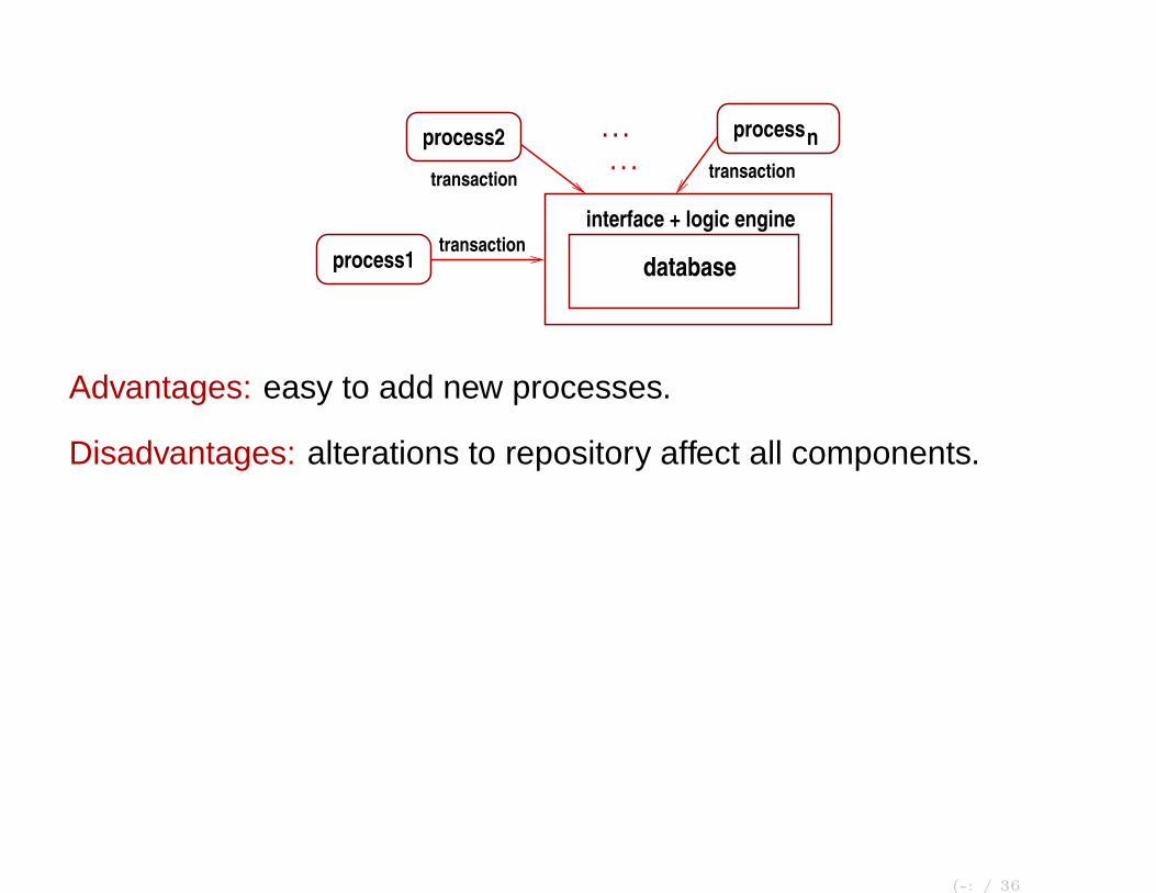
Repositories: databases and blackboards
interface + logic engine
databaseprocess1
process2 processn
transaction
transaction transaction
. . .
. . .
Database Blackboard
Components: processes and database knowledge sources and
blackboardConnectors: queries and updates notifications and updates
Constraints: transactions (queries and
updates) drive computation
knowledge sources respond
when enabled by the state of theblackboard. Problem is solved
by cooperative computation onblackboard.
Examples: speech and pattern recognition (blackboard); syntaxeditors and compilers (parse tree and symbol table are repositories)
(-: / 35
interface + logic engine
databaseprocess1
process2 processn
transaction
transaction transaction
. . .
. . .
Advantages: easy to add new processes.
Disadvantages: alterations to repository affect all components.
(-: / 36

Independent components: communicating processes
process
process
process
αβ γ
δ
Communicating processes
Components: processes (“tasks”)
Connectors: ports or buffers or RPC
Constraints: processes execute in parallel and send mes-
sages (synchronously or asynchronously)
Example: client-server and peer-to-peer architectures
Advantages: easy to add and remove processes. Disadvantages: difficult to reason
about control flow.
(-: / 37

Independent components: event systems
object
object
object
event registry
!
?
!
!
?
Event systems
Components: objects or processes (“threads”)
Connectors: event broadcast and notification (implicit invocation)
Constraints:components “register” to receive event notifi-
cation; components signal events, environment
notifies registered “listeners”
Examples: GUI-based systems, debuggers, syntax-directed editors,database consistency checkers
(-: / 38

object
object
object
event registry
!
?
!
!
?
Advantages: easy for new listeners to register and unregister
dynamically; component reuse.
Disadvantages: difficult to reason about control flow and to formulate
system-wide invariants of correct behavior.
(-: / 39
Other forms of architecture
Process control system: Structured as a feedback loop where input
from sensors trigger computation whose outputs adjust the physical
environment. For controlling a physical environment, e.g., software for
flight control.
State transition system: Structured as a finite automaton; for reactive
systems, e.g., vending machines.
Domain-specific software architectures: architectures tailored to
specific application areas. Requires a domain model, which lists
domain-specific objects, operations, vocabulary. Requires a reference
architecture, which is a generic depiction of the desired architecture.
The architecture is then instantiated and refined into the desired
software architecture.
Examples: Client-server models like CORBA, DCOM (in .NET), Enterprise
Javabeans (in J2EE).
(-: / 40
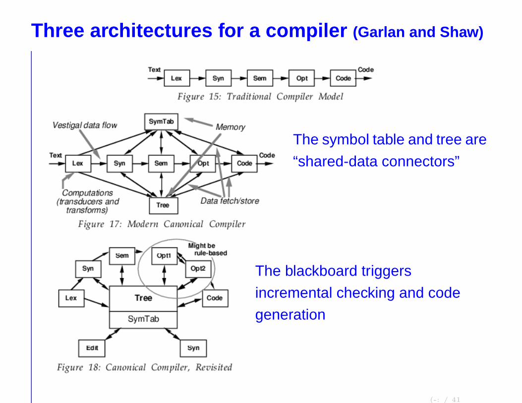
Three architectures for a compiler (Garlan and Shaw)
The symbol table and tree are
“shared-data connectors”
The blackboard triggers
incremental checking and code
generation
(-: / 41
What do we gain from using a softwarearchitecture?
1. the architecture helps us communicate the system’s designto the project’s stakeholders (users, managers,implementors)
2. it helps us analyze design decisions
3. it helps us reuse concepts and components in futuresystems
(-: / 42

An example of an application andits software architectureAn architecture that is heavily used for single-user, GUI-based
applications is the Model-View-Controller (MVC) architecture.
(-: / 43
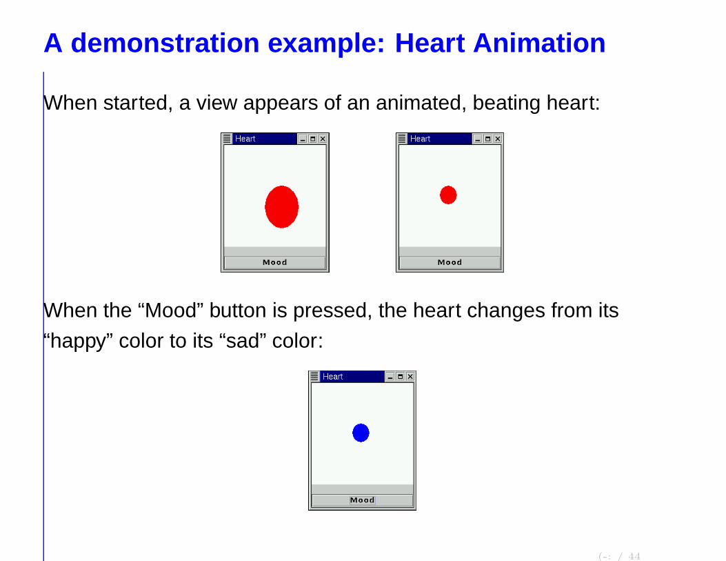
A demonstration example: Heart Animation
When started, a view appears of an animated, beating heart:
When the “Mood” button is pressed, the heart changes from its
“happy” color to its “sad” color:
(-: / 44

But there is another view of the heart—two additional windows display
the state of the heart in terms of its history of happy and sad beats:
The heart is modelled within the animation and is viewed in two
different ways (by color and counts). It is controlled by a “clock” and a
Mood button.
The source code is available at www.cis.ksu.edu/santos/schmidt/ppdp01/Heart
(-: / 45

MVC Architecture of the Heart Animation
while true {heart.beat();}
heart.resetMood();
size = ++size mod2;mood.increment();notifyObservers();
mood = ++mood mod2;notifyObservers();
! update
HeartbeatController
run()
MoodController
actionPerformed()
size:{large,small}
Heart
beat()
mood: {happy, sad}
resetMood()
Counter
increment()
ActionListenerupdate()
HeartWriter
CounterWriter
update()
Observer
update()
Observable
notifyObservers()
JButton
heart
sad
happy
? actionPerformed
heart
? update
! actionPerformed
! press
? update
MVC is a hybrid architecture: the subassemblies are object-oriented and are
connected as an event system. (The java.util and javax.swing packages
implement the event registries.)
(-: / 46

HeartbeatController
run()
actionPerformed()
MoodController
size:{large,small}
Heart
beat()
resetMood()
mood: {happy, sad}
Counter
increment()
update()
HeartWriterCounterWriter
update()
VIEW(S)
MODELCONTROLLER(S)
MVC
Components: classes and interfaces (to event registries)
Connectors: call-return message passing, event broadcast
Properties:
Architecture is divided into Model, View, and
Controller subassemblies. Controller updates
Model’s state; when updated, Model signals
View(s) to revise presentation.
(-: / 47
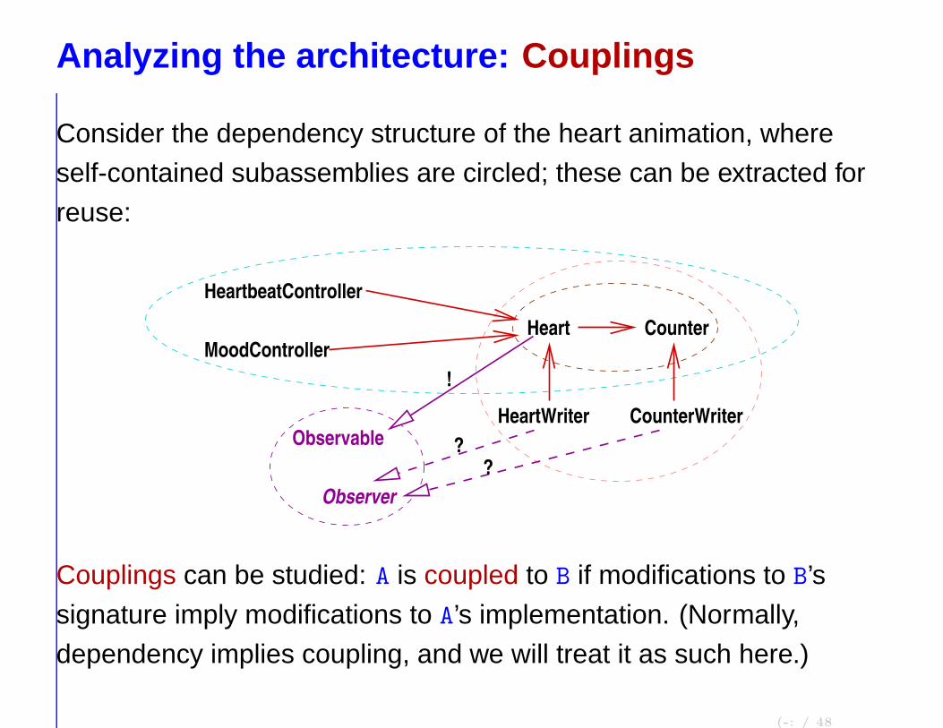
Analyzing the architecture: Couplings
Consider the dependency structure of the heart animation, where
self-contained subassemblies are circled; these can be extracted for
reuse:
HeartbeatController
MoodControllerHeart Counter
Observable
Observer
HeartWriter CounterWriter
!
??
Couplings can be studied: A is coupled to B if modifications to B’s
signature imply modifications to A’s implementation. (Normally,
dependency implies coupling, and we will treat it as such here.)
(-: / 48

As a general rule, a system should have weak coupling — changes to
a component imply minimal changes to the rest of the system.
(But data-centered systems, like a database, have strong coupling — all user
processes are coupled to the database, making changes to the database expensive!)
In the example, the Observer/Observable event registry decouples
the animation’s controllers from its views and ensures that the model
is decoupled from all other subassemblies:
HeartbeatController
MoodControllerHeart Counter
Observable
Observer
HeartWriter CounterWriter
!
??
(-: / 49

Without the Observer event registry, we might design the animation
like this, where the controllers tell the model to update and tell the
views to refresh:
HeartbeatController
MoodControllerHeart Counter
HeartWriter CounterWriter
The structure is hierarchical, coupling the controllers to all
subassemblies; unfortunately, the controllers operate only with fixed
views.
(-: / 50

An alternative is to demand that the model contact all views whenever
it is updated:
HeartbeatController
MoodControllerHeart Counter
CounterWriterHeartWriter
This looks clean, but the model controls the views! And it operates
only with fixed views.
Both of the latter two architectures will be difficult to maintain as the
system evolves. Subassembly reuse is unlikely.
The first architecture is the best; indeed, it uses the observer design
pattern.
(-: / 51

Design patterns
(-: / 52

When an architectural (sub)design proves successful in multiple
projects, it defines a design pattern that can be used in future
designs. The model and view subassemblies of the animation,
Observable
Observer
Heart Counter
HeartWriter CounterWriter
!
HeartbeatController
MoodController
?
?
are assembled according to the observer design pattern:
ConcreteSubject
state
getState()
setState()
ConcreteObserver
copyOfState
handle()
Observer
handle()
Observable
Observer[] registered
register(Observer)
notify()
?
s
rr
!
(-: / 53

A design pattern is a solution scheme to a common architectural
problem that arises in a specific context. It is presented by
� stating the problem and the context in which it arises
� stating the solution in terms of an architectural structure (syntax)
� describing the behavior (semantics) of the structure
� assessing the pragmatics
Varieties:
1. Creational: patterns for constructing components
2. Structural: patterns for connecting components
3. Behavioral: patterns for communicating between components
Reference: E. Gamma, et al., Design Patterns: Elements of Reusable
Object-Oriented Software. Addison Wesley, 1994.
(-: / 54

A behavioral pattern: observer
Problem Context: Maintain consistency of copies of state amongmultiple objects, where one object’s state must be “mirrored” by all theothers.
The pattern designates one subject object to hold the state; observerobjects hold the copies and are notified by indirect event broadcastwhen the subject’s state changes. The observers then query thesubject and copy the state changes.
Syntax: ConcreteSubject
state
getState()
setState()
ConcreteObserver
copyOfState
handle()
Observer
handle()
Observable
Observer[] registered
register(Observer)
notify()
?
s
rr
!
(-: / 55

ConcreteSubject
state
getState()
setState()
ConcreteObserver
copyOfState
handle()
Observer
handle()
Observable
Observer[] registered
register(Observer)
notify()
?
s
rr
!
Semantics:
I. The ConcreteSubject owns an event registry, r. Observable.
II. Each ConcreteObserver invokes r.register(this), registering itself.
III. When the ConcreteSubject’s setState method is invoked, the methodupdates state and signals r.notify(), which broadcasts events to allregistered[i], starting these objects’ handle methods.
IV. Each handle method invokes s.getState() and updates its local state.
Pragmatics:
✔ weak coupling: the subject knows nothing about its observers
✔ observers are readily added, modified, and detached
✘ a minor state update signals all observers
(-: / 56
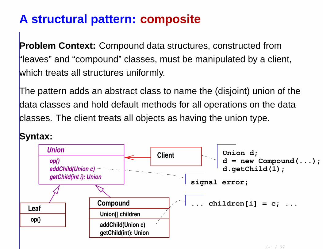
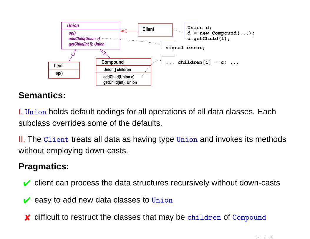
A structural pattern: composite
Problem Context: Compound data structures, constructed from
“leaves” and “compound” classes, must be manipulated by a client,
which treats all structures uniformly.
The pattern adds an abstract class to name the (disjoint) union of the
data classes and hold default methods for all operations on the data
classes. The client treats all objects as having the union type.
Syntax:
signal error;
Union d;d = new Compound(...);d.getChild(1);
... children[i] = c; ...
Union
op()
addChild(Union c)
getChild(int i): Union
Leaf
op()
Compound
Union[] children
addChild(Union c)
getChild(int): Union
Client
(-: / 57
signal error;
Union d;d = new Compound(...);d.getChild(1);
... children[i] = c; ...
Union
op()
addChild(Union c)
getChild(int i): Union
Leaf
op()
Compound
Union[] children
addChild(Union c)
getChild(int): Union
Client
Semantics:
I. Union holds default codings for all operations of all data classes. Eachsubclass overrides some of the defaults.
II. The Client treats all data as having type Union and invokes its methodswithout employing down-casts.
Pragmatics:
✔ client can process the data structures recursively without down-casts
✔ easy to add new data classes to Union
✘ difficult to restruct the classes that may be children of Compound
(-: / 58

A creational pattern: abstract factory
Problem Context: A client uses a “product family” (e.g., widgets —windows, scroll bars, menus), constructed on demand. The clientmust be separate from the family so that the family can be easilychanged (e.g., a different “look and feel”).
The pattern uses an interface to list the constructors for the products,and each family implements the interface.
Syntax:AbstractFactory
createA(): AbsProductA
createB(): AbsProductB
ConcreteFactory2
createA(): AbsProductA
createB(): AbsProductB
ConcreteFactory1
createA(): AbsProductA
createB(): AbsProductB ProductB1 ProductB2
AbsProductB
ProductA1 ProductA2
AbsProductA
Client
(-: / 59

AbstractFactory
createA(): AbsProductA
createB(): AbsProductB
ConcreteFactory2
createA(): AbsProductA
createB(): AbsProductB
ConcreteFactory1
createA(): AbsProductA
createB(): AbsProductB ProductB1 ProductB2
AbsProductB
ProductA1 ProductA2
AbsProductA
Client
Semantics:
I. The AbstractFactory interface is implemented by one ofConcreteFamily1 or ConcreteFamily2, and interfaces AbsProductA andAbsProductB are implemented by the respective concrete products.
II. The Client invokes the methods in AbstractFactory to receive objectsof type AbsProduct1 and AbsProduct2 — it does not know the identities ofthe concrete products.
Pragmatics:
✔ Client is decoupled from the products it uses
✔ interface AbstractFactory forces all product families to be consistent
✘ it is difficult to add new products to just one factory
(-: / 60

Of course, the abstract factory pattern is a compensation for the lack
of a polymorphic class — but it does indicate a context when the
“polymorphism” can be profitably applied.
And the composite pattern is a compensation for the lack of a disjoint
union type — but it does indicate a context when disjoint union can be
profitably applied.
In this sense, design patterns are universal across programming
paradigms, although each programming paradigm will support some
design patterns more simply than others.
(-: / 61

3. Architectural analysis andviews
(-: / 62

How do we classify architectural styles?
1. Forms of components and connectors. See earlier slides.
2. Control-flow: how control is transferred, allocated, and shared.topology: geometric shape of control — linear, hierarchical, hub-and-spoke.
Static or dynamic. synchronicity: lockstep, synchronous, asynchronous. binding
time: when the partner of a transfer of control is established: compile-, link-, or
run-time.
3. Data-flow: how data is communicated through the system.topology: geometric shape of the data flow; continuity: continuous, sporadic,
high-volume, low-volume flow; mode: how data is transferred: passed, shared,
copy-in-copy-out (from shared structure), broadcast, or multicast.
4. Control/data interaction. shape: are control/data topologies similar?
directionality: do data and control travel in the same direction?
5. Which form of reasoning is compatible with the style? state machine
theory/process algebra (for independent components); function composition (for
pipe-and-filter); inductive/compositional (for hierarchical).
(-: / 63

(The pipe-and-filter example seen earlier is called pipeline here.)
Reference: M. Shaw and P. Clements. A Field Guide to Boxology: Preliminary
Classification of Architectural Styles for Software Systems. Proc. COMPSAC’97,
21st Int’l Computer Software and Applications Conference, August 1997, pp. 6-13.
(-: / 64
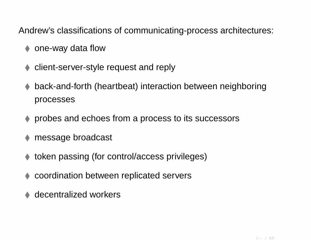
Andrew’s classifications of communicating-process architectures:
� one-way data flow
� client-server-style request and reply
� back-and-forth (heartbeat) interaction between neighboring
processes
� probes and echoes from a process to its successors
� message broadcast
� token passing (for control/access privileges)
� coordination between replicated servers
� decentralized workers
(-: / 65

(-: / 66

A two-slide table of architectural styles:
(-: / 67

(-: / 68

How do we select a style of softwarearchitecture?
Shaw gives this simple checklist from A Field Guide to Boxology,
COMPSAC’97:
(1) If the problem can be decomposed into sequential stages,consider a data-flow architecture: batch sequential or pipeline.
In addition, if each stage is incremental, so that later stages can beginbefore earlier stages finish, consider a pipeline architecture.
(2) If the problem involves transformations on continuous streams ofdata (or on very long streams), consider a pipeline architecture.
But the problem passes “rich” data representations, avoid pipelinesrestricted to ASCII.
(3) If the central issues are understanding the data of the application,its management, and representation, consider a repository orabstract-data-type architecture. If the data is long-lived, focus on
(-: / 69
repositories.
If the representation of data is likely to change over the lifetime of the
program, than abstract data types can confine the changes to
particular components.
If you are considering repositories and the input data has a low
signal-to-noise ratio and the execution order cannot be
predetermined, consider a blackboard.
If you are considering repositories and the execution order is
determined by a stream of incoming requests and the data is highly
structured, consider a database management system.
(4) If your system involves controlling continuing action, is embedded
in a physical system, and is subject to unpredictable external
pertubation so that preset algorithms go wrong, consider a
closed-loop control architecture.
(-: / 70

(5) If you have designed a computation but have no machine on which
you can execute it, consider an interpreter architecture.
(6) If your task requires a high degree of flexibility/configurability,
loose coupling between tasks, and reactive tasks, consider interacting
processes.
If you have reason not to bind the recipients of signals from their
originators, consider an event architecture.
If the tasks are of a hierarchical nature, consider a replicated worker
or heartbeat style.
If the tasks are divided between producers and consumers, consider
client/server.
If it makes sense for all of the tasks to communicate with each other in
a fully connected graph, consider a token-passing style.
(-: / 71

Architectural views: stating and satisfying requirements
A building is too complex to be described in just one way — multiple
views are presented. An architect might draw these views:
� floor plans
� elevation drawings
� electrical and plumbing diagrams
� traffic patterns
� sunlight and solar views
The views help show how the building’s requirements are satisfied by
the architecture.
But the views also direct the implementation: Some of the views are “aspects” that
might be “woven” into the construction; others are “properties” of the construction
(that should be monitored or enforced).
(-: / 72
Process-driven design: 4+1 view model (Kruchten)
A software architecture might be “viewed” four different ways:
1. logical: behavior requirements — key abstractions (classes,objects), data and control flowuse UML class, collaboration, and sequence diagrams
2. development: organization of software packagesuse UML package diagrams
3. process: distribution, concurrency, coordination, synchronizationuse UML activity diagrams
4. physical: deployment onto hardware — performance, reliability,scalabilityuse UML deployment diagrams
Finally, scenarios (use-cases) direct show how the views “worktogether”
(-: / 73

Using UML class, collaboration ,and sequence diagramsto present the logical view:
From Mikko Kontio, IBM,
http://www-128.ibm.com/
developerworks/wireless/
library/wi-arch11/
(-: / 74

Using package diagrams to present the development view anddeployment diagrams to present the physical view:
(-: / 75

4. Architecture DescriptionLanguages
(-: / 76

A language for connectors: UniCon
Shaw developed a language, UniCon (Universal Connector
Language), for describing connectors and components.
Components are specified by interfaces , which include(i) type;
(ii) attributes with values that specialize the type;
(iii) players, which are the component’s connection points. Each
player is itself typed.
Connectors are specified by protocols ; they have(i) type;
(ii) specific properties that specialize the type;
(iii) roles that the connector uses to mediate (make) communication
between components.
(-: / 77
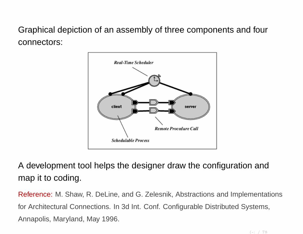
Graphical depiction of an assembly of three components and fourconnectors:
A development tool helps the designer draw the configuration andmap it to coding.
Reference: M. Shaw, R. DeLine, and G. Zelesnik, Abstractions and Implementations
for Architectural Connections. In 3d Int. Conf. Configurable Distributed Systems,
Annapolis, Maryland, May 1996.
(-: / 78

uses statements in-
stantiate the parts
composed
connect statements
state how players sat-
isfy roles
bind statements map
the external interface to
the internal configura-
tion
(-: / 79

Connectors described in UniCon:
� data-flow connectors (pipe)
� procedural connectors (procedure call, remote procedure call):
pass control
� data-sharing connectors (data access): export and import data
� resource-contention connectors (RT scheduler): competition for
resources
� aggregate connectors (PL bundler): compound connections
(-: / 80

(-: / 81

(-: / 82

(-: / 83

(-: / 84

Wright : Unicon + CSP
Garlan and Allen developed Wright to specify protocols. Here is a
single-client/single-server example:
The protocols are specified with Hoare’s CSP (Communicating
Sequential Processes) algebra.
(-: / 85
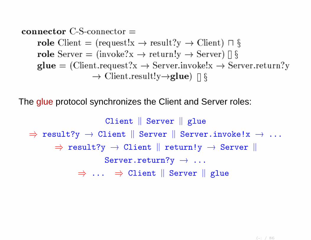
The glue protocol synchronizes the Client and Server roles:
Client || Server || glue
⇒ result?y → Client || Server || Server.invoke!x → ...
⇒ result?y → Client || return!y → Server ||
Server.return?y → ...
⇒ ... ⇒ Client || Server || glue
(-: / 86

Forms of CSP processes:
� prefixing: e → P
plusOne?x → return!x + 1 → · · · || plusOne!2 → return?y → · · ·
⇒ return!2 + 1 → · · · || return?y → · · ·
� external choice: P[]Q
plusOne?x → · · · [] plusTwo?x → · · · x + 2 · · · || plusTwo!5 → · · ·
⇒ · · · 5 + 2 · · · || · · ·
� internal choice: P ⊓ Q
plusOne?x → · · · || plusOne!5 → · · · ⊓ plusTwo!5 → · · ·
⇒ plusOne?x → · · · || plusTwo!5 → · · ·
� parallel composition: P||Q
� halt: §
� (tail) recursion: p = · · · p (More formally, µz.P, where z may occurfree in P.)
(-: / 87

A pipe protocol in Wright
Reference: R. Allen and D. Garlan. A formal basis for architectural connection. ACM
TOSEM 1997.
(-: / 88
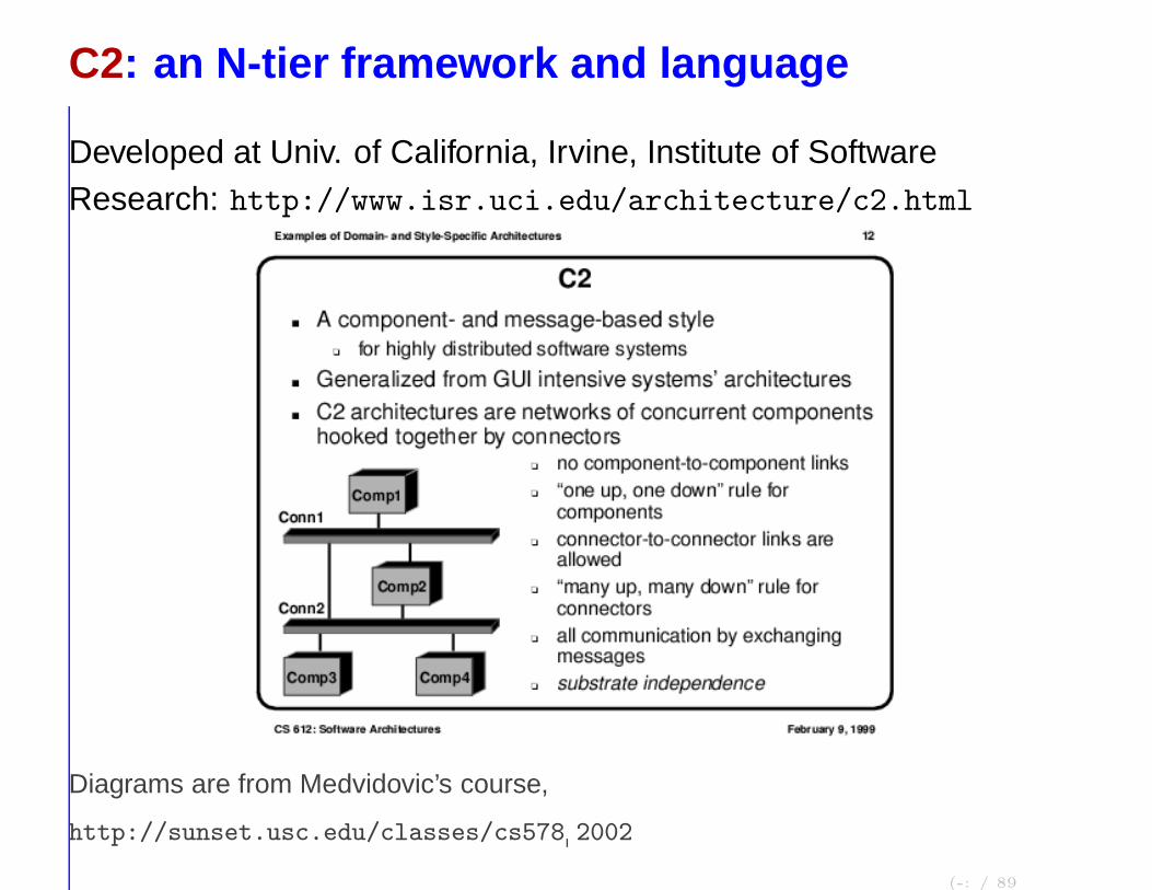
C2: an N-tier framework and language
Developed at Univ. of California, Irvine, Institute of SoftwareResearch: http://www.isr.uci.edu/architecture/c2.html
Diagrams are from Medvidovic’s course,
http://sunset.usc.edu/classes/cs578 2002
(-: / 89

Example architecture in C2: video game
(-: / 90

Here is a C2SADEL description of the video game’s “Well”component:
Reference: N. Medvidovic, et al. A Language and Environment for
Architecture-Based Software Development and Evolution. 21st Int. Conf. on
Software Engineering, Los Angeles, May 1999.
(-: / 91

And here is a description of a connector and part of the configuration:
(-: / 92
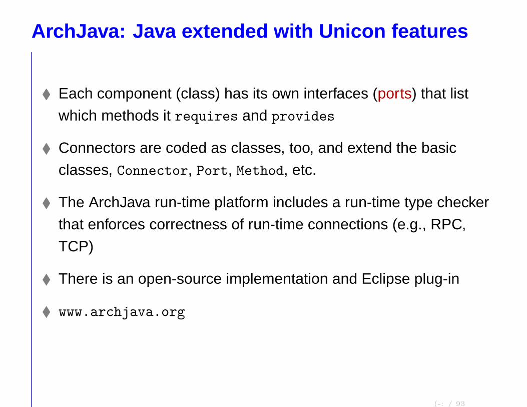
ArchJava: Java extended with Unicon features
� Each component (class) has its own interfaces (ports) that list
which methods it requires and provides
� Connectors are coded as classes, too, and extend the basic
classes, Connector, Port, Method, etc.
� The ArchJava run-time platform includes a run-time type checker
that enforces correctness of run-time connections (e.g., RPC,
TCP)
� There is an open-source implementation and Eclipse plug-in
� www.archjava.org
(-: / 93

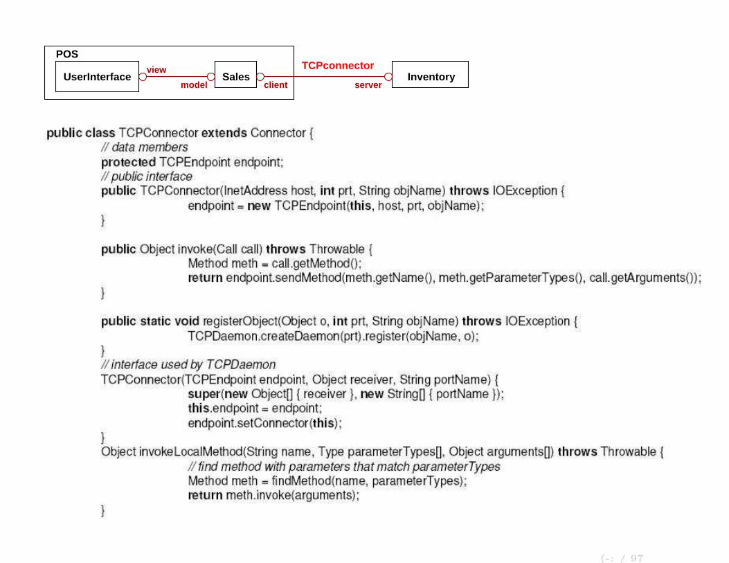
POS
UserInterface Sales Inventoryview
model client
TCPconnector
server
(-: / 94
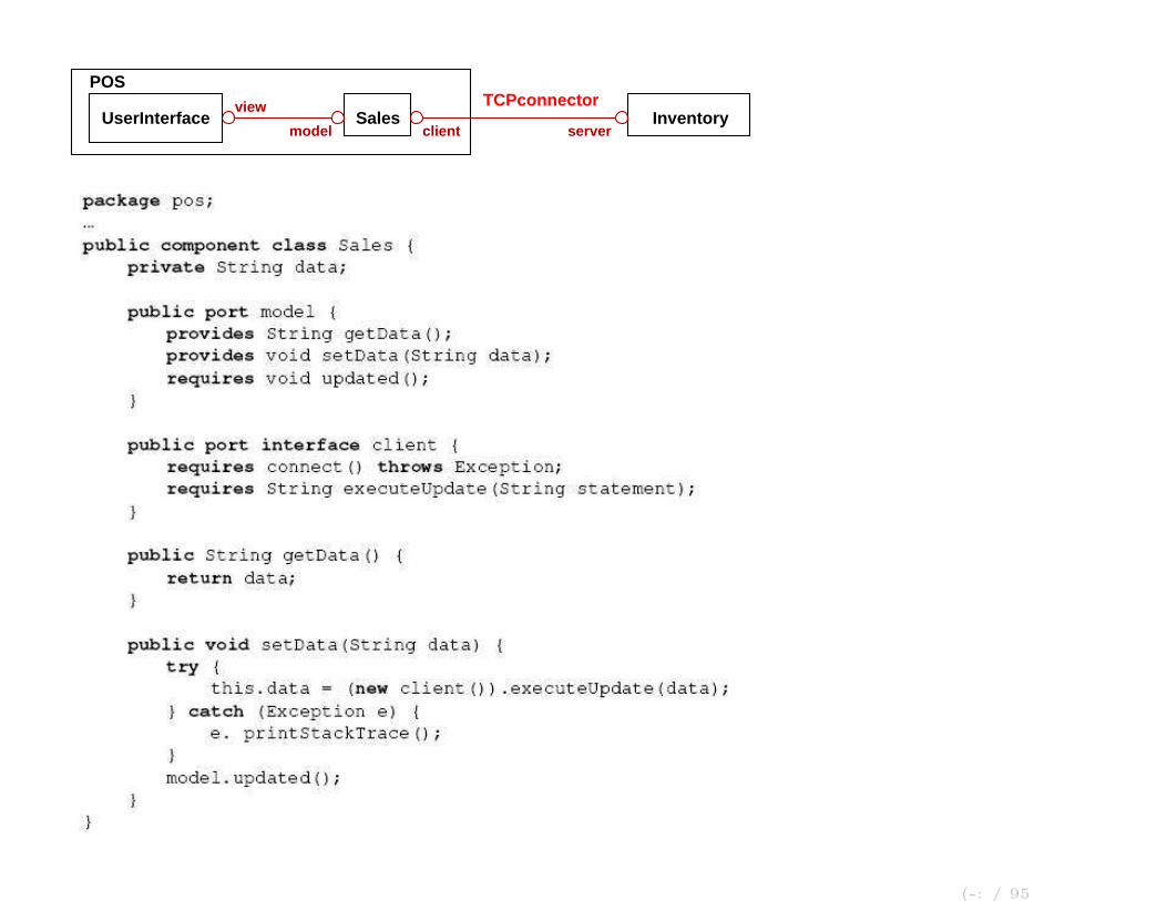
POS
UserInterface Sales Inventoryview
model client
TCPconnector
server
(-: / 95

POS
UserInterface Sales Inventoryview
model client
TCPconnector
server
From K. M. Hansen, www.daimi.dk/∼marius/teaching/ATiSA2005
(-: / 96
POS
UserInterface Sales Inventoryview
model client
TCPconnector
server
(-: / 97

A summary of some ADLs
From K. M. Hansen, www.daimi.dk/∼marius/teaching/ATiSA2005
(-: / 98

(-: / 99
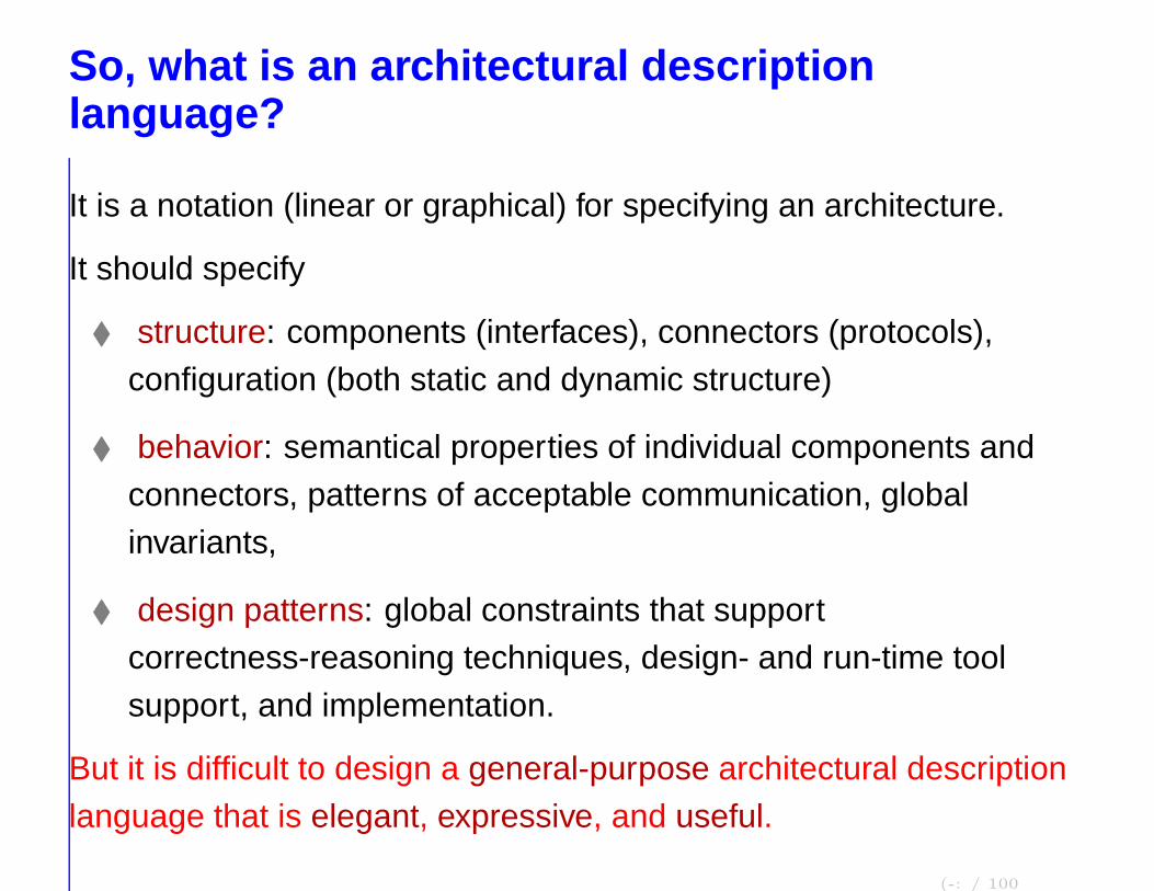
So, what is an architectural descriptionlanguage?
It is a notation (linear or graphical) for specifying an architecture.
It should specify
� structure: components (interfaces), connectors (protocols),configuration (both static and dynamic structure)
� behavior: semantical properties of individual components and
connectors, patterns of acceptable communication, globalinvariants,
� design patterns: global constraints that supportcorrectness-reasoning techniques, design- and run-time tool
support, and implementation.
But it is difficult to design a general-purpose architectural description
language that is elegant, expressive, and useful.
(-: / 100

5. Domain-specific design
(-: / 101

Domain-specific design
If the problem domain is a standard one (e.g., flight-control or
telecommunications or banking), then there are precedents to follow.
A Domain-Specific Software Architecture has
� a domain: defines the problem area domain concepts and terminology;
customer requirements; scenarios; configuration models (entity-relationship,
data flow, etc.)
� reference requirements: features that restrict solutions to fit the
domain. (“Features” are studied shortly.) Also: platform, language, user
interface, security, performance
� a reference architecture
� a supporting environment/infrastructure: tools for modelling,
design, implementation, evaluation; run-time platform
� a process or methodology to implement the reference
architecture and evaluate it.
(-: / 102
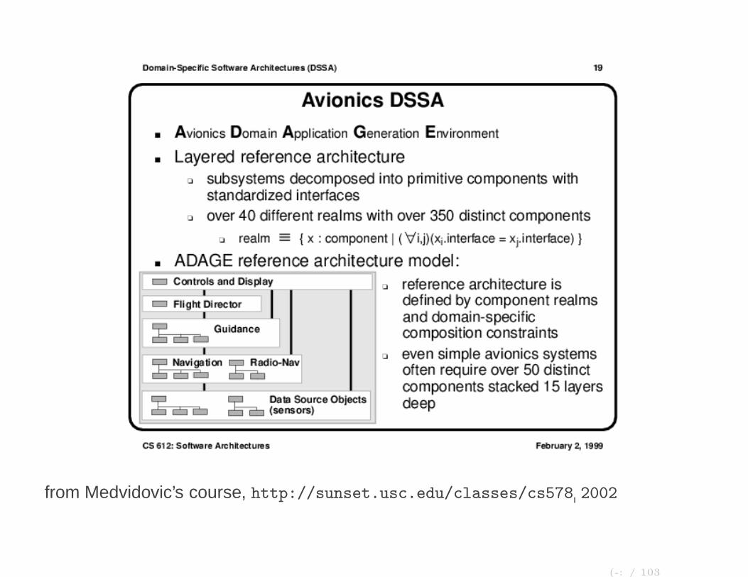
from Medvidovic’s course, http://sunset.usc.edu/classes/cs578 2002
(-: / 103
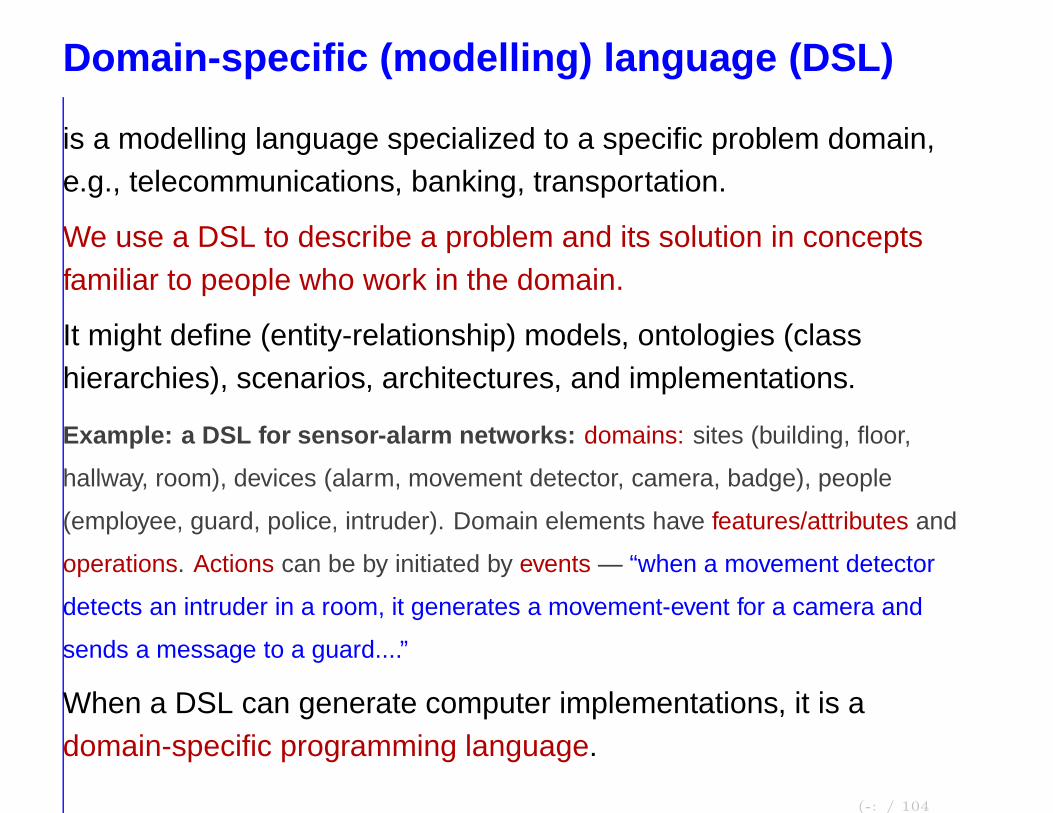
Domain-specific (modelling) language (DSL)
is a modelling language specialized to a specific problem domain,e.g., telecommunications, banking, transportation.
We use a DSL to describe a problem and its solution in conceptsfamiliar to people who work in the domain.
It might define (entity-relationship) models, ontologies (classhierarchies), scenarios, architectures, and implementations.
Example: a DSL for sensor-alarm networks: domains: sites (building, floor,
hallway, room), devices (alarm, movement detector, camera, badge), people
(employee, guard, police, intruder). Domain elements have features/attributes and
operations. Actions can be by initiated by events — “when a movement detector
detects an intruder in a room, it generates a movement-event for a camera and
sends a message to a guard....”
When a DSL can generate computer implementations, it is adomain-specific programming language.
(-: / 104

Domain-specific programming language
In the Unix world, these are “little languages” or “mini-languages,”
designed to solve a specific class of problems. Examples are awk,
make, lex, yacc, ps, and Glade (for GUI-building in X).
Other examples are Excel, HTML, XML, SQL, regular-expression
notation and BNF. These are called top-down DSLs, because they are
designed to implement domain concepts and nothing more.
Non-programmers can use a top-down DSL to write solutions.
The bottom-up approach, called embedded or in-language DSL,
starts with a dynamic-data-structure language, like Scheme or Perl or
Python, and adds libraries (modules) of functions that encode
domain-concepts-as-code, thus “building the language upwards
towards the problem to be solved.” Experienced programmers use
bottom-up DSLs to program solutions.
(-: / 105

Tradeoffs in using (top-down) DSLs
✔ non-programmers can discuss and use the DSL
✔ the DSL supports patterns of design, implementation, and
optimization
✔ fast development
✘ staff must be trained to use the DSL
✘ interaction of DSL-generated software with other software
components can be difficult
✘ there is high cost in developing and maintaining a DSL
Reference: J. Lawall and T. Mogensen. Course on Scripting Languages and DSLs,
Univ. Copenhagen, 2006, www.diku.dk/undervisning/2006f/213
(-: / 106

From DSLs to product lines (Steve Cook, Microsoft)
A model is a representation, written in a DSL, whose elementscorrespond to domain elements/concepts. It helps stakeholders(users, managers, implementors) communicate about the system.
A framework is a collection of components that implement thedomain’s aspects/features. (Example: GUI frameworks)
The model should show how to build upon or extend theframework to generate an application.
A pattern is a “model with holes” with rules for filling the holes.
A value chain is a manufacturing process where each participanttakes inputs (goods or information) from suppliers, adds “value,” andpasses the output to the successors in the chain.
A product line is a value chain for software construction, based onmodels, patterns, and frameworks:requirements engineer → architect → developer → tester → user
(-: / 107

6. Software product lines
(-: / 108

A software product line
is also called a software system family — a collection of softwareproducts that share an architecture and components, constructed bya product line. They are inspired by the products produced byindustrial assembly lines, e.g., automobiles.
The CMU Software Engineering Institute definition:
A product line is a set of software intensive systems that(i) share a common set of features,
(ii) satisfy the needs of a particular mission, and(iii) are developed from a set of core assets in a prescribed w ay.
Key issues:variability: Can we state precisely the products’ variations (features) ?guidance: Is there a precise recipe that guides feature selection andproduct assembly?
Reference: www.softwareproductlines.com
(-: / 109

An example product line: Cummins Corporation
produces diesel engines for trucks and heavy machinery. An engine
controller has 100K-200K lines-of-code. At level of 12 engine “builds,”
company switched to a product line approach:
1. defined engine controller domain
2. defined a reference architecture
3. built reusable components
4. required all teams to follow product line approach
Cummins now produces 20 basic “builds” — 1000 products total;
development time dropped from 250 person/months to < 10. A new
controller consists of 75% reused software.
Reference: S. Cohen. Product line practice state of the art report.
CMU/SEI-2002-TN-017.
(-: / 110

Features and feature diagrams
are a development tool for domain-specific architectures and product
lines. They help define a domain’s reference requirements and guide
implementions of instances of the reference architecture.
A feature is merely a property of the domain. (Example: the
features/options/choices of an automobile that you order from the
factory.)
A feature diagram displays the features and guides a user in choosing
features for the solution to a domain problem.
It is a form of decision tree with and-or-xor branching, and its
hierarchy reflects dependencies of features as well as modification
costs.
(-: / 111

Feature diagram for assembling automobiles
enginetransmission
manualautomatic electric gasoline
pullsTrailorbody
car
Filled circles label required features; unfilled circles label optional
ones. Filled arcs label xor-choices; unfilled arcs label or-choices
(where at least one choice is selected).
Here is one possible outcome of “executing” the feature diagram:
car
manual transmission
engine
gaselectric
body
(-: / 112
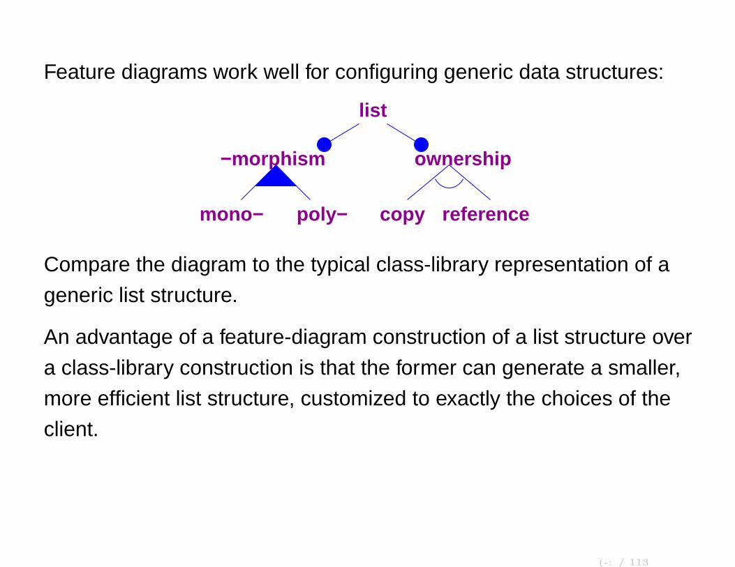
Feature diagrams work well for configuring generic data structures:
−morphism
list
mono− poly−
ownership
copy reference
Compare the diagram to the typical class-library representation of a
generic list structure.
An advantage of a feature-diagram construction of a list structure over
a class-library construction is that the former can generate a smaller,
more efficient list structure, customized to exactly the choices of the
client.
(-: / 113

Feature diagrams are useful for both constraining as well as
generating an architecture: the feature requirements are displayed in
a feature diagram, which guides the user to generating the desired
instance of the reference architecture.
Feature diagrams are an attempt at making software assembly appear
similar to assembly of mass-produced products like automobiles.
In particular, feature diagrams encourage the use of standardized,
parameterized, reusable software components.
Feature diagrams might be implemented by a tool that selects
components according to feature selection. Or, they might be
implemented within the structure of a domain-specific programming
language whose programs select and assemble features.
Reference: K. Czarnecki and U. Eisenecker. Generative Programming.
Addison-Wesley 2000.
(-: / 114

Feature generation is implemented by
Reference: D. Muthig, Software product lines and reengineering. Fraunhofer Inst.
2002
(-: / 115

Generative programming
is the name given to the application of programs that generate other
programs (cf. “automatic programming” in the 1950s). A compiler is of
course a generating program, but so are feature-diagram-driven
frameworks, partial evaluators, and some development environments
(e.g., for Java beans).
Reference: Coming attractions in software architecture, P. Clements. CMU/SEI-96-TR-008.
(-: / 116

Generative programming is motivated by the belief that conventionalsoftware production methods (even those based on “object-oriented”methodologies) will never support component reuse:
Reference: Jan Bosch. Design and Use of Software Architectures. Addison-Wesley, 2000.
One solution is to understand a software system as a customizedproduct, produced by generative programming, from a product line.
Reference: K. Czarnecki and U. Eisenecker. Generative Programming.
Addison-Wesley 2000.
(-: / 117

Software factories
A software factory combines DSLs, patterns, models, frameworks,
tools, and guidance to “accelerate life-cycle tasks for a type of
software application” [Steve Cook, Microsoft].
That is, it is a kind of “product line” for assembling the correct
language, architecture, and software components for a software
project — a kind of software-industrial engineering.
DSLs and XML provide the language for assembling and using the
software factory.
The goal is complete automation of sofware development — no more
coding (except in DSLs (-: )
Reference: J. Greenfield, et al. Software Factories, Wiley, 2004. See also Microsoft
Visual Studio Team 2005.
(-: / 118
7. Middleware
(-: / 119

Middleware : a popular form of domain-specificsoftware architecture
Middleware lies between hardware and software in the design ofindependent-component (e.g., client-server) architectures.Middleware is also called a distributed component platform. It gives
� standards for writing the APIs (and code) for components (andconnectors) so that they can connect, communicate, and bereused. The standards are independent of any particularprogramming language, allowing heterogeneous (different stylesof) components to be used together.
� prebuilt components, connectors, and interfaces, along with adevelopment environment, for assembling an architecture.
Middleware provides “smart” connectors that hide the details behindcommunication. The user writes components that conform to themiddleware’s standards/APIs.
(-: / 120

Middleware typically demands these hardware services:
� remote communication protocols
� global naming services
� security services
� data transmission services
Warning! The term, “middleware,” is overused — almost any tool that
provides a run-time platform is called “middleware.”
(-: / 121

CORBA: Common Object Request BrokerArchitecture
CORBA is middleware for building distributed, object-based,
client-server architectures; developed by the Object Management
Group (OMG).
Components communicate through a centralized service, the Object
Request Broker (ORB).
An object can be a client or a server (or both).
To use the ORB, a server component must implement an API
(interface) that lets it connect to an object adapter, which itself
connects to the ORB. (Object adapters contain code for object
registration with a global naming service, reference generation, and
server activation).
(-: / 122

Object adapters are available in Java, C++, Perl, etc.; components arewritten in these languages and communicate via procedure calls.
The physical locations of objects are hidden — references, held in anaming service, are used instead.
The implementations of objects are hidden.
The communications protocols (TCP/IP, RPC, ...) are hidden.
Only the interfaces are known.
Diagram is from: S. Vinoski. CORBA: Integrating Diverse Applications Within
Distributed Heterogeneous Environments. IEEE Communications, Feb. 1997.
(-: / 123
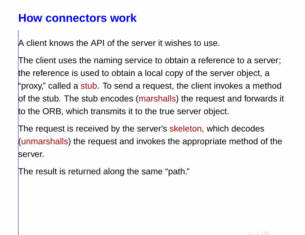
How connectors work
A client knows the API of the server it wishes to use.
The client uses the naming service to obtain a reference to a server;
the reference is used to obtain a local copy of the server object, a
“proxy,” called a stub. To send a request, the client invokes a method
of the stub. The stub encodes (marshalls) the request and forwards it
to the ORB, which transmits it to the true server object.
The request is received by the server’s skeleton, which decodes
(unmarshalls) the request and invokes the appropriate method of the
server.
The result is returned along the same “path.”
(-: / 124

(-: / 125

From the client’s perspective, a send connection looks like a method
invocation:
Reference: S. Vinoski. CORBA. IEEE Communications, Feb. 1997.
(-: / 126

Structure of the Reference Model for CORBA
An implementation of CORBA must support this structure:
Object Services are interfaces for the ORB, providing transmission,security, and server lookup by naming and “trading” (property).Domain Interfaces are the object interfaces for the problem area(telecommunication, financial, medical).Application Interfaces are object interfaces for the application; writtenby the software architect.
(-: / 127

CORBA has become popular because it is a standard that is
supported by many programming languages. Its architecture is useful
because it allows heterogenous components that communicate by
implementing interfaces: the ORB interfaces, the object-adapter
interfaces, the stub and skeleton interfaces.
But CORBA has some disadvantages, too:
� the architecture is difficult to optimize
� there is no deadlock detection nor garbage collection (in the
middleware)
� all objects are treated as potentially remote
� all object’s references are stored in a global database
(-: / 128

DCOM: Microsoft’s Distributed ObjectComponent Model (now in .NET)
has similar objectives and structure as CORBA but tries toaddress some of CORBA’s deficiencies:
supports reference-counting garbage collection (uses “pinging” to
detect inactive clients)
batches together multiple method calls (and pings) to minimize
network “round trips”
exploits locality: thread-local and machine-local method calls are
implemented more efficiently than RPCs. Uses a virtual table to standardize
method call lookup and hide the differences between implementations
makes it easier to program proxy objects and implement dynamic load
balancing
allows a component to learn dynamically the interface of another.
But it uses a different IDL and interfaces than CORBA’s )-:
(-: / 129

Reference: DCOM Technical Overview. Microsoft Windows/NT white paper, 1996.
(-: / 130

DCOM uses a virtual table to implement communication, as functioncall, as efficiently as possible:
Reference: http://sunset.usc.edu/classes/cs578 2002
(-: / 131

Java beans: middleware for Java
A Java bean is a reusable (Java-coded) component, that can bemanipulated (its attributes set and its methods executed) both atdesign-time and run-time.
For this reason, a bean has a design-time interface and a separaterun-time interface — this is the key architectural concept for beans.The design-time interface almost always includes a GUI that is displayed by the
builder tool.
The run-time interface lists properties (attributes), methods, and events that the bean
possesses.
The interfaces are more general than usual: they include “properties”(attributes – local state), methods, and event broadcast-listening. Theinterfaces need not be written by the programmer; they can beextracted from the bean by a development tool.
A development tool (the bean box) uses a bean’s design-time
(-: / 132

interface to help an application builder position a bean in the
application, customize its appearance, and select its run-time
behaviors (methods).
Java beans were originally tailored towards GUI-building applications
— buttons, text fields, and sliders are obvious candidates for beans —
but the concept also works for data structures and algorithms.
Examples:
� insert a sorting-algorithm-bean into a spreadsheet bean
� insert a spreadsheet bean into a table bean
� insert a table bean into a web-page bean
(-: / 133

A calculator and its assembly via beans:
Examples are from http://www.tcs.tifr.res.in/man/javaTutorial/beans
(-: / 134

Java beans communicate by Java-style event broadcast; a bean can
be an event source or an event listener or both.
Beans execute within a run-time environment, a form of middleware.
The environment broadcasts and delivers events; it rests on top of the
Java Virtual Machine.
Because it is complex to construct the design-time and run-time
interfaces, beans have an introspection facility, based on a Java
interface Property, which the development tool uses to extract the
bean’s interfaces.
The extraction is done in a primitive way: the bean must use standard
naming conventions for its attributes, methods, and events (e.g.,
addListener, removeListener, get, set). Better, the programmer
can write a class BeanInfo whose methods surrender the
property-method-event interfaces.
(-: / 135

The Java Bean Box: a simple development tool
Slide is from http://sunset.usc.edu/classes/cs578 2002
(-: / 136

Beans and remote access
(-: / 137

Servlets: beans as proxies
(-: / 138
Enterprise Java Beans (EJB) (now in J2EE)
are a variant of Java beans (and not truly compatible with them),
oriented to client-server applications.
An EJB is a servlet-like object that is remotely constructed by a client,
using methods in the server’s home interface. The EJB is placed in a
container (an “adaptor” or “wrapper”) that receives the client’s
transaction, decodes it, and gives it to the EJB. Such an EJB is called
a session bean.
(An entity bean is an EJB that is shared by multiple clients; it has no
internal state.)
The EJB implements methods in the remote interface, which are the
method names invoked by the client to request transactions.
The client uses methods in the home interface to remove the session
bean.
(-: / 139

(-: / 140

8. Model-driven architecture
(-: / 141

An imprecise description: a model-driven architecture is software
(architecture) development based on a model written in a modelling
language. (Example: using UML to describe and suggest
implementation of a system.)
A slightly more precise description: a model-driven architecture is
a two-stage software architecture development:
1. starting at the “business level,” define a platform-independent
model (PIM) of the system,
2. now at the “architectural level,” map the PIM to a platform specific
model (PSM) at the “technology level.”
3. implement the required PSM interfaces
But the most precise description comes from the OMG’s response
to the CORBA/COM/EJB competition....
(-: / 142

The OMG’s MDA methodology
CORBA, EJB (now, J2EE), DCOM (now, .NET) are competingframeworks for building client-server architectures. There are eveninterchange languages for mapping between their IDLs.
The OMG defined a “meta-model” (the PIM) of client-server andmappings from the PIM to PSMs for CORBA, J2EE, etc.
The PIM is to be written in UML2, which is UML extended to writePIMs. (UML2 includes concepts from SPL, a telecommunicationsdesign language.)
The mapping from PIM to PSM maps architecture, data forms, andIDL to the PSM’s. A mapping from the client-server PIM to J2EE iswell underway.
Advantages: hides multiplicities of programming languages, IDLs, etc.; supports
upgrades of the PSMs. Disadvantages: requires two more meta- languages, MOF
and XMI; relies heavily on UML2; unclear it will map to non-J2EE PSMs
(-: / 143

From MDA to MDE and DSM
The name, “Model Driven Architecture,” is trademarked by the OMG
and refers to multi-level models using UML2.
The key ideas,
1. use a hierarchy of models (“business model,” ..., platform-specific
model) to define a software architecture;
2. refine each model at level i to the model at lower level, i − 1;
are now popular and are called Model Driven Engineering (MDE).
Domain Specific Modelling (DSM) is MDE using a hierarchy of DSLs:
Each model is coded in a DSL, and translators map each
domain-specific program to a (doman-specific) program at the next
lower-level (and finally to assembly code).
Reference: www.dsmforum.org
(-: / 144

9. Aspect-oriented programming
(-: / 145
Recall Kruchten’s 4 views of software:
1. logical: behavioral and functional requirements2. process: concurrency, coordination, and synchronization3. development: organization of software modules4. physical: deployment onto hardware
Each view tells us how to code part of the software.
Kiczales at Xerox PARC said that software contains aspects :
� functional behavior (what the software “does”)� synchronization and security control� error handling� persistency and memory management� monitoring and logging
Each aspect tells us how to code part of the software.
But the aspect’s codings “cross cut” the functional components andare “scattered” throughout the program.
(-: / 146

Example: a synchronized stack in Java: functional code in black,
synchronization code in red, error-handling in blue:
public class Stack
{ private int top; private Object[] elements;
public Stack(int size) { elements = new Object[size]; top = 0; }
public synchronized void push(Object element) {while (top == elements.length) {
try { wait(); } catch (InterruptedException e) { ... }}elements[top] = element; top++;if (top == 1) { notifyAll(); } // signal that stack is nonempty
}
public synchronized Object pop() {while (top == 0) {
try { wait(); } catch (InterruptedException e) { ... }}top--; Object return val = elements[top];if (top < elements.length) { notifyAll(); } // stack not full
return return val;} }
(-: / 147

The synchronized stack example is not so elegant:
� The various aspects are “tangled” (intertwined) in the code, and it
is difficult to see which lines of code compute which aspect.
� One aspect is divided (“scattered”) across many components; if
there is a change in the aspect, many components must be
rewritten.
� It is difficult to study and code an aspect separately.
(-: / 148
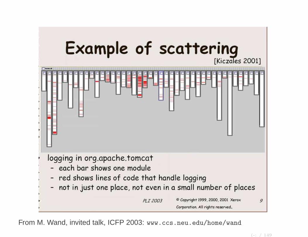
From M. Wand, invited talk, ICFP 2003: www.ccs.neu.edu/home/wand
(-: / 149

How do we code and integrate an aspect?
Kiczales proposed that each aspect be coded separately and theaspects be woven together by a tool called a weaver. The weaverinserts code at connection points, called join points.
A standard join point is a method call; another is (the entry and exitpoints of) a method’s definition. Join points can be field declarationsor even references to variable names (e.g., for monitoring).
The aspects should be
� noninvasive: one aspect should not be written specially to allow itto be “woven into” by another
� orthogonal: one aspect does not interfere with the local, logicalproperties of another
� minimal coupling: aspects can be unconnected and reused
Normally, other aspects are woven into the functional aspect.
(-: / 150

Wrappers implement simple aspects
When join points are method definitions, where an aspect merely
adds code before method entry and after exit, then we can mimick
weaving with a wrapper.
Example: pre-condition error checking via a subclass-wrapper:
public class NumericalOperator {public double square root(double d) { ... } }
public class NumericalWrapper extends NumericalOperator {public double square root(double m) { // check that m>= 0 :
double answer;if (m >= 0) { answer = super.square root(m); }
else { throw new RuntimeException( ... ) }return answer; }
}
The technique is simple but inelegant — it changes the name of
class NumericalOperator. Also, one quickly obtains too many layers
of wrappers.
(-: / 151

Composition filters: “smart wrappers”
Filters integrate “local” as well as “global” aspects, in both “horizontal”
and “vertical” composition:
L. Bergmans, The composition filters object model, Computer Science, Univ. Twente,
1994.
(-: / 152

Lopes developed COOL: A language dedicated tosynchronization aspects
// In a separate Java file, write the functional component:public class Stack {
private int top; private Object[] elements;
public Stack(int size) { elements = new Object[size]; top = 0; }
public void push(Object element) { elements[top] = element; top++; }
public Object pop() { top--; return elements[top]; }}
// In a separate Cool file, state the synchronization policy:coordinator Stack {
selfex push, pop; // self exclusive methodsmutex { push, pop }; // mutually exclusive methodscondition full = false; condition empty = true;
guard push: requires !full;onexit { if (empty) empty = false; }
guard pop: requires !empty;onexit { if (full) full = false;
if (top == 0) empty = true; }}
(-: / 153

When the two classes are woven, the result is the synchronized stack:
public class Stack{ private int top; private Object[] elements;
private boolean empty; private boolean full;
public Stack(int size){ elements = new Object[size]; top = 0;full = false; empty = true; }
public synchronized void push(Object element) {while (full) {
try { wait(); } catch (InterruptedException e) { }}elements[top] = element; top++;if (empty) { empty = false; notifyAll(); }
}
public synchronized Object pop() {while (empty) {
try { wait(); } catch (InterruptedException e) { }}top--; Object return val = elements[top];if (top == 0) empty = true;if (full) { full = false; notifyAll(); }return return val;
} }
(-: / 154

The COOL language looks somewhat like a language for writing
connectors!
Indeed, when join points are method calls or method definitions, then
weaving two aspects is weaving the connector code into the
component code!
(-: / 155

Weaving automata: Colcombet and Fradet
Program and aspect might be represented as automata and woveninto a product automaton (enforces policies for error handling,synchronization):
From T. Colcombet and P. Fradet. Enforcing trace properties by program
transformation, ACM POPL 2000.
(-: / 156

The policy, program, and product automaton:
(-: / 157

Aspects as coordinators
An aspect is sometimes specified as a global “coordinator” thatenforces a synchonization or security policy:
coordinator(policy)
clients
The coordinator is coded separately, and the weaver distributes thecoordinator’s code into the clients, giving distributed coordination.(Partial evaluators do this weaving.) The result looks like CORBA:
clients
residualcoordinator
localcoordinator
(-: / 158

Subject-oriented programming
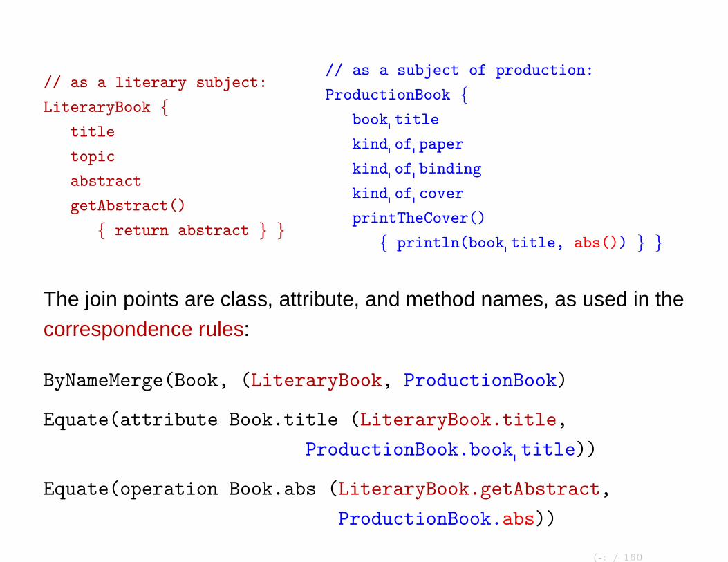
IBM (Harrison and Ossher): a subject is an aspect of a data structure.
Example: a book viewed in two different ways
// as a literary subject:
LiteraryBook {
title
topic
abstract
getAbstract()
{ return abstract }
}
// as a subject of production:
ProductionBook {
book title
kind of paper
kind of binding
kind of cover
printTheCover()
{ println(book title, abs()) }
}
These look like multiple interfaces or abstract classes (c.f. Java
beans); the Book class is assembled from the subjects, which are
“unioned” (a kind of tensor product) using correspondence rules.
(-: / 159
// as a literary subject:
LiteraryBook {
title
topic
abstract
getAbstract()
{ return abstract } }
// as a subject of production:
ProductionBook {
book title
kind of paper
kind of binding
kind of cover
printTheCover()
{ println(book title, abs()) } }
The join points are class, attribute, and method names, as used in thecorrespondence rules:
ByNameMerge(Book, (LiteraryBook, ProductionBook)
Equate(attribute Book.title (LiteraryBook.title,
ProductionBook.book title))
Equate(operation Book.abs (LiteraryBook.getAbstract,
ProductionBook.abs))
(-: / 160

We are moving towards programming-language support for these
formats of interface, connection, and implementation. Examples:
� Jiazzi: www.cs.utah.edu/plt/jiazzi/
� GenVoca/AHEAD: www.cs.utexas.edu/users/schwartz
� composition filters:
http://trese.ewi.utwente.nl/oldhtml/composition filters
� subject-oriented programming: www.research.ibm.com/sop
� COOL/RIDL: Lopes, C. A Language Framework for Distributed
Programming. PhD thesis, Northeastern Univ., 1998.
� AspectJ: www.parc.com/research/csl/projects/aspectj
These are the “modern-day” architectural description languages! See
www.generative-programming.org for an overview.
(-: / 161

10. Final Remarks
(-: / 162

Reference: Jan Bosch. Design and Use of Software Architectures. Addison-Wesley,
2000.
(-: / 163

(-: / 164

Selected textbook references
F. Buschmann, et al. Pattern-Oriented Software Architecture. Wiley
1996.
P. Clements and L. Northrup. Software Product Lines.
Addison-Wesley 2002.
P. Clements, et al. Documenting Software Architectures: Views and
Beyond. Addison Wesley, 2002.
K. Czarnecki and U. Eisenecker. Generative Programming.
Addison-Wesley 2000.
E. Gamma, et al. Design Patterns: Elements of Reusable
Object-Oriented Software. Addison Wesley, 1994.
M. Shaw and D. Garlan. Software Architecture. Prentice Hall 1996.
(-: / 165