Embed Size (px)
Citation preview
Pacific Graphics 2013B. Levy, X. Tong, and K. Yin(Guest Editors)
Volume 32 (2013), Number 7
Soft Folding
L. Zhu1,3 T. Igarashi1,3 J. Mitani2,3
1The University of Tokyo 2University of Tsukuba 3JST ERATO
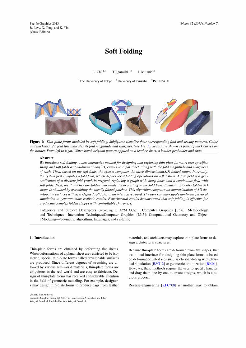
Figure 1: Thin-plate forms modeled by soft folding. Subfigures visualize their corresponding fold and sewing patterns. Colorand thickness of a fold line indicates its fold magnitude and sharpness(see Fig. 5). Seams are shown as pairs of thick curves onthe border. From left to right: Water-bomb origami pattern applied on a leather sheet, a leather penholder and shoe.
AbstractWe introduce soft folding, a new interactive method for designing and exploring thin-plate forms. A user specifiessharp and soft folds as two-dimensional(2D) curves on a flat sheet, along with the fold magnitude and sharpnessof each. Then, based on the soft folds, the system computes the three-dimensional(3D) folded shape. Internally,the system first computes a fold field, which defines local folding operations on a flat sheet. A fold field is a gen-eralization of a discrete fold graph in origami, replacing a graph with sharp folds with a continuous field withsoft folds. Next, local patches are folded independently according to the fold field. Finally, a globally folded 3Dshape is obtained by assembling the locally folded patches. This algorithm computes an approximation of 3D de-velopable surfaces with user-defined soft folds at an interactive speed. The user can later apply nonlinear physicalsimulation to generate more realistic results. Experimental results demonstrated that soft folding is effective forproducing complex folded shapes with controllable sharpness.
Categories and Subject Descriptors (according to ACM CCS): Computer Graphics [I.3.6]: Methodologyand Techniques—Interaction Techniques;Computer Graphics [I.3.5]: Computational Geometry and Objec-t Modeling—Geometric algorithms, languages, and systems;
1. Introduction
Thin-plate forms are obtained by deforming flat sheets.When deformations of a planar sheet are restricted to be iso-metric, special thin-plate forms called developable surfacesare produced. Since different degrees of stretching are al-lowed by various real-world materials, thin-plate forms areubiquitous in the real world and are easy to fabricate. De-sign of thin-plate forms has received considerable attentionin the field of geometric modeling. For example, designer-s may design thin-plate forms to produce bags from leather
materials, and architects may explore thin-plate forms to de-sign architectural structures.
Because thin-plate forms are deformed from flat shapes, thetraditional interface for designing thin-plate forms is basedon deformation interfaces such as click-and-drag with phys-ical simulation [BSG12] or geometric optimization [BK04].However, these methods require the user to specify handlesand drag them one-by-one to create designs, which is a te-dious process.
Reverse-engineering [KFC∗08] is another way to obtain
c⃝ 2013 The Author(s)Computer Graphics Forum c⃝ 2013 The Eurographics Association and JohnWiley & Sons Ltd. Published by John Wiley & Sons Ltd.
L. Zhu & T. Igarashi & J. Mitani / Soft Folding
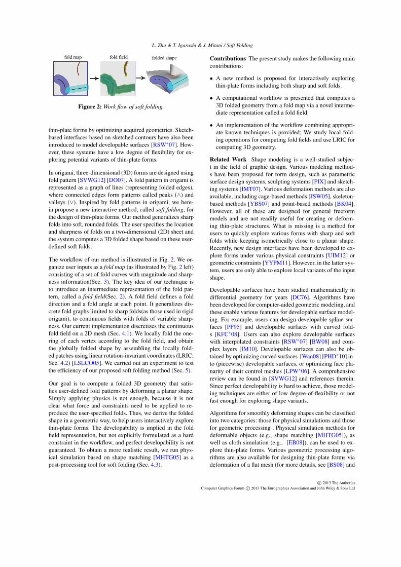
fold map fold field folded shape
Figure 2: Work flow of soft folding.
thin-plate forms by optimizing acquired geometries. Sketch-based interfaces based on sketched contours have also beenintroduced to model developable surfaces [RSW∗07]. How-ever, these systems have a low degree of flexibility for ex-ploring potential variants of thin-plate forms.
In origami, three-dimensional (3D) forms are designed usingfold pattern [SVWG12] [DO07]. A fold pattern in origami isrepresented as a graph of lines (representing folded edges),where connected edges form patterns called peaks (∧) andvalleys (∨). Inspired by fold patterns in origami, we here-in propose a new interactive method, called soft folding, forthe design of thin-plate forms. Our method generalizes sharpfolds into soft, rounded folds. The user specifies the locationand sharpness of folds on a two-dimensional (2D) sheet andthe system computes a 3D folded shape based on these user-defined soft folds.
The workflow of our method is illustrated in Fig. 2. We or-ganize user inputs as a fold map (as illustrated by Fig. 2 left)consisting of a set of fold curves with magnitude and sharp-ness information(Sec. 3). The key idea of our technique isto introduce an intermediate representation of the fold pat-tern, called a fold field(Sec. 2). A fold field defines a folddirection and a fold angle at each point. It generalizes dis-crete fold graphs limited to sharp folds(as those used in rigidorigami), to continuous fields with folds of variable sharp-ness. Our current implementation discretizes the continuousfold field on a 2D mesh (Sec. 4.1). We locally fold the one-ring of each vertex according to the fold field, and obtainthe globally folded shape by assembling the locally fold-ed patches using linear rotation-invariant coordinates (LRIC;Sec. 4.2) [LSLCO05]. We carried out an experiment to testthe efficiency of our proposed soft folding method (Sec. 5).
Our goal is to compute a folded 3D geometry that satis-fies user-defined fold patterns by deforming a planar shape.Simply applying physics is not enough, because it is notclear what force and constraints need to be applied to re-produce the user-specified folds. Thus, we derive the foldedshape in a geometric way, to help users interactively explorethin-plate forms. The developability is implied in the foldfield representation, but not explicitly formulated as a hardconstraint in the workflow, and perfect developability is notguaranteed. To obtain a more realistic result, we run phys-ical simulation based on shape matching [MHTG05] as apost-processing tool for soft folding (Sec. 4.3).
Contributions The present study makes the following maincontributions:
• A new method is proposed for interactively exploringthin-plate forms including both sharp and soft folds.
• A computational workflow is presented that computes a3D folded geometry from a fold map via a novel interme-diate representation called a fold field.
• An implementation of the workflow combining appropri-ate known techniques is provided; We study local fold-ing operations for computing fold fields and use LRIC forcomputing 3D geometry.
Related Work Shape modeling is a well-studied subjec-t in the field of graphic design. Various modeling method-s have been proposed for form design, such as parametricsurface design systems, sculpting systems [PIX] and sketch-ing systems [IMT07]. Various deformation methods are alsoavailable, including cage-based methods [JSW05], skeleton-based methods [YBS07] and point-based methods [BK04].However, all of these are designed for general freeformmodels and are not readily useful for creating or deform-ing thin-plate structures. What is missing is a method forusers to quickly explore various forms with sharp and softfolds while keeping isometrically close to a planar shape.Recently, new design interfaces have been developed to ex-plore forms under various physical constraints [UIM12] orgeometric constraints [YYPM11]. However, in the latter sys-tem, users are only able to explore local variants of the inputshape.
Developable surfaces have been studied mathematically indifferential geometry for years [DC76]. Algorithms havebeen developed for computer-aided geometric modeling, andthese enable various features for developable surface model-ing. For example, users can design developable spline sur-faces [PF95] and developable surfaces with curved fold-s [KFC∗08]. Users can also explore developable surfaceswith interpolated constraints [RSW∗07] [BW08] and com-plex layers [IM10]. Developable surfaces can also be ob-tained by optimizing curved surfaces [Wan08] [PHD∗10] in-to (piecewise) developable surfaces, or optimizing face pla-narity of their control meshes [LPW∗06]. A comprehensivereview can be found in [SVWG12] and references therein.Since perfect developability is hard to achieve, those model-ing techniques are either of low degree-of-flexibility or notfast enough for exploring shape variants.
Algorithms for smoothly deforming shapes can be classifiedinto two categories: those for physical simulations and thosefor geometric processing . Physical simulation methods fordeformable objects (e.g., shape matching [MHTG05]), aswell as cloth simulation (e.g., [EB08]), can be used to ex-plore thin-plate forms. Various geometric processing algo-rithms are also available for designing thin-plate forms viadeformation of a flat mesh (for more details, see [BS08] and
c⃝ 2013 The Author(s)Computer Graphics Forum c⃝ 2013 The Eurographics Association and John Wiley & Sons Ltd
L. Zhu & T. Igarashi & J. Mitani / Soft Folding
θα
v
D S
F
v
α,θ
θ
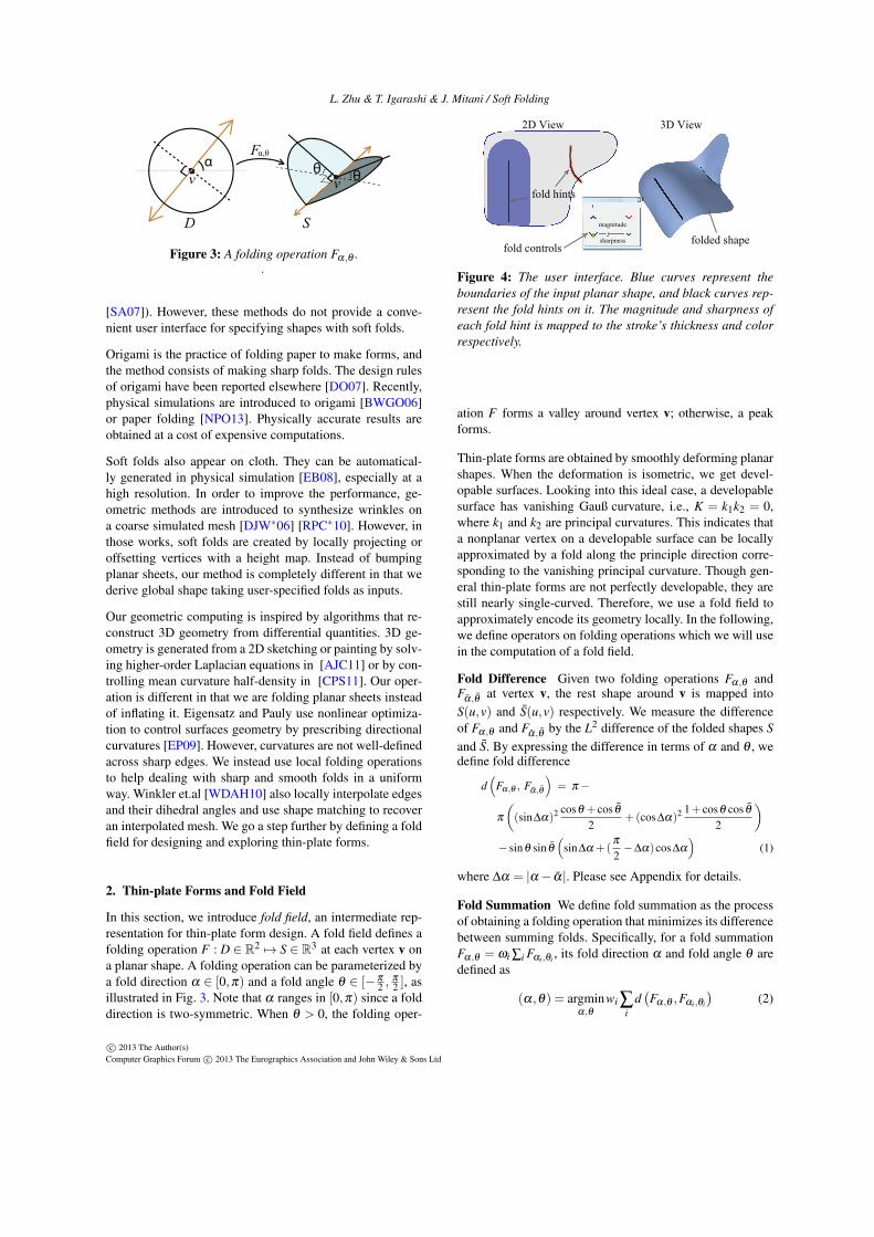
Figure 3: A folding operation Fα,θ ..
[SA07]). However, these methods do not provide a conve-nient user interface for specifying shapes with soft folds.
Origami is the practice of folding paper to make forms, andthe method consists of making sharp folds. The design rulesof origami have been reported elsewhere [DO07]. Recently,physical simulations are introduced to origami [BWGO06]or paper folding [NPO13]. Physically accurate results areobtained at a cost of expensive computations.
Soft folds also appear on cloth. They can be automatical-ly generated in physical simulation [EB08], especially at ahigh resolution. In order to improve the performance, ge-ometric methods are introduced to synthesize wrinkles ona coarse simulated mesh [DJW∗06] [RPC∗10]. However, inthose works, soft folds are created by locally projecting oroffsetting vertices with a height map. Instead of bumpingplanar sheets, our method is completely different in that wederive global shape taking user-specified folds as inputs.
Our geometric computing is inspired by algorithms that re-construct 3D geometry from differential quantities. 3D ge-ometry is generated from a 2D sketching or painting by solv-ing higher-order Laplacian equations in [AJC11] or by con-trolling mean curvature half-density in [CPS11]. Our oper-ation is different in that we are folding planar sheets insteadof inflating it. Eigensatz and Pauly use nonlinear optimiza-tion to control surfaces geometry by prescribing directionalcurvatures [EP09]. However, curvatures are not well-definedacross sharp edges. We instead use local folding operationsto help dealing with sharp and smooth folds in a uniformway. Winkler et.al [WDAH10] also locally interpolate edgesand their dihedral angles and use shape matching to recoveran interpolated mesh. We go a step further by defining a foldfield for designing and exploring thin-plate forms.
2. Thin-plate Forms and Fold Field
In this section, we introduce fold field, an intermediate rep-resentation for thin-plate form design. A fold field defines afolding operation F : D ∈ R2 7→ S ∈ R3 at each vertex v ona planar shape. A folding operation can be parameterized bya fold direction α ∈ [0,π) and a fold angle θ ∈ [− π
2 ,π2 ], as
illustrated in Fig. 3. Note that α ranges in [0,π) since a folddirection is two-symmetric. When θ > 0, the folding oper-
2D View 3D View
folded shape
fold hints
fold controls
magnitude
sharpness
Figure 4: The user interface. Blue curves represent theboundaries of the input planar shape, and black curves rep-resent the fold hints on it. The magnitude and sharpness ofeach fold hint is mapped to the stroke’s thickness and colorrespectively.
ation F forms a valley around vertex v; otherwise, a peakforms.
Thin-plate forms are obtained by smoothly deforming planarshapes. When the deformation is isometric, we get devel-opable surfaces. Looking into this ideal case, a developablesurface has vanishing Gauß curvature, i.e., K = k1k2 = 0,where k1 and k2 are principal curvatures. This indicates thata nonplanar vertex on a developable surface can be locallyapproximated by a fold along the principle direction corre-sponding to the vanishing principal curvature. Though gen-eral thin-plate forms are not perfectly developable, they arestill nearly single-curved. Therefore, we use a fold field toapproximately encode its geometry locally. In the following,we define operators on folding operations which we will usein the computation of a fold field.
Fold Difference Given two folding operations Fα,θ andFα,θ at vertex v, the rest shape around v is mapped intoS(u,v) and S(u,v) respectively. We measure the differenceof Fα,θ and Fα,θ by the L2 difference of the folded shapes Sand S. By expressing the difference in terms of α and θ , wedefine fold difference
d(
Fα,θ , Fα,θ
)= π −
π((sin∆α)2 cosθ + cos θ
2+(cos∆α)2 1+ cosθ cos θ
2
)− sinθ sin θ
(sin∆α +(
π2−∆α)cos∆α
)(1)
where ∆α = |α − α |. Please see Appendix for details.
Fold Summation We define fold summation as the processof obtaining a folding operation that minimizes its differencebetween summing folds. Specifically, for a fold summationFα,θ = ωi ∑i Fαi,θi , its fold direction α and fold angle θ aredefined as
(α,θ) = argminα,θ
wi ∑i
d(Fα,θ ,Fαi,θi
)(2)
c⃝ 2013 The Author(s)Computer Graphics Forum c⃝ 2013 The Eurographics Association and John Wiley & Sons Ltd
L. Zhu & T. Igarashi & J. Mitani / Soft Folding
large sharpnesssmall sharpness
large
positive magnitudesmall magnitude
large
negative magnitude
s = 1s = 0
θ = πθ = -π
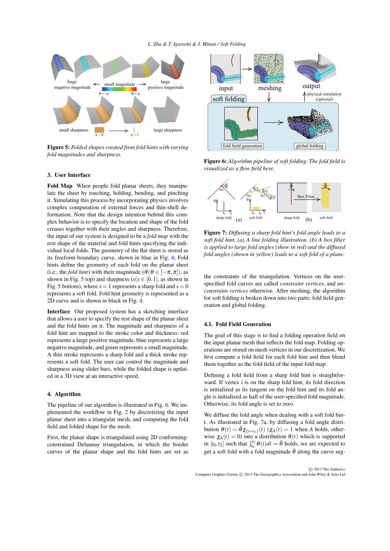
Figure 5: Folded shapes created from fold hints with varyingfold magnitudes and sharpness.
3. User Interface
Fold Map When people fold planar sheets, they manipu-late the sheet by touching, holding, bending, and pinchingit. Simulating this process by incorporating physics involvescomplex computation of external forces and thin-shell de-formation. Note that the design intention behind this com-plex behavior is to specify the location and shape of the foldcreases together with their angles and sharpness. Therefore,the input of our system is designed to be a fold map with therest shape of the material and fold hints specifying the indi-vidual local folds. The geometry of the flat sheet is stored asits freeform boundary curve, shown in blue in Fig. 4; Foldhints define the geometry of each fold on the planar sheet(i.e., the fold hint) with their magnitude (θ(θ ∈ [−π,π]), asshown in Fig. 5 top) and sharpness (s(s ∈ [0,1], as shown inFig. 5 bottom), where s = 1 represents a sharp fold and s = 0represents a soft fold. Fold hint geometry is represented as a2D curve and is shown in black in Fig. 4.
Interface Our proposed system has a sketching interfacethat allows a user to specify the rest shape of the planar sheetand the fold hints on it. The magnitude and sharpness of afold hint are mapped to the stroke color and thickness: redrepresents a large positive magnitude, blue represents a largenegative magnitude, and green represents a small magnitude.A thin stroke represents a sharp fold and a thick stroke rep-resents a soft fold. The user can control the magnitude andsharpness using slider bars, while the folded shape is updat-ed in a 3D view at an interactive speed.
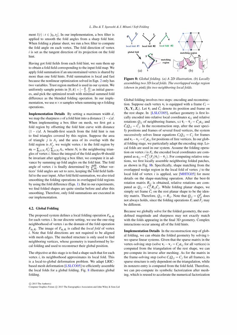
4. Algorithm
The pipeline of our algorithm is illustrated in Fig. 6. We im-plemented the workflow in Fig. 2 by discretizing the inputplanar sheet into a triangular mesh, and computing the foldfield and folded shape for the mesh.
First, the planar shape is triangulated using 2D conforming-constrained Delaunay triangulation, in which the bordercurves of the planar shape and the fold hints are set as
input meshing
global folding
output
soft foldingphysical simulation
(optional)
fold field generation
Figure 6: Algorithm pipeline of soft folding. The fold field isvisualized as a flow field here.
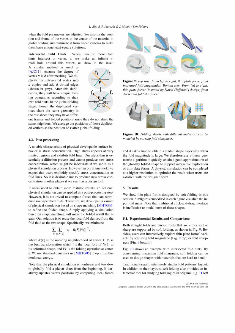
sharp fold soft fold(a) (b) soft foldsharp fold
θl(t1)
l(t0) l(t2)
t
θ
t1 t
θ
t0 t2
Box Filter
θ θθ/3
θ/3
θ/3
Figure 7: Diffusing a sharp fold hint’s fold angle leads to asoft fold hint. (a) A line folding illustration. (b) A box filteris applied to large fold angles (show in red) and the diffusedfold angles (shown in yellow) leads to a soft fold of a plane.
the constraints of the triangulation. Vertices on the user-specified fold curves are called constraint vertices, and un-constraint vertices otherwise. After meshing, the algorithmfor soft folding is broken down into two parts: fold field gen-eration and global folding.
4.1. Fold Field Generation
The goal of this stage is to find a folding operation field onthe input planar mesh that reflects the fold map. Folding op-erations are stored on mesh vertices in our discretization. Wefirst compute a fold field for each fold hint and then blendthem together as the fold field of the input fold map.
Defining a fold field from a sharp fold hint is straightfor-ward. If vertex i is on the sharp fold hint, its fold directionis initialized as its tangent on the fold hint and its fold an-gle is initialized as half of the user-specified fold magnitude.Otherwise, its fold angle is set to zero.
We diffuse the fold angle when dealing with a soft fold hin-t. As illustrated in Fig. 7a, by diffusing a fold angle distri-bution θ(t) = θ χ{t=t1}(t) (χA(t) = 1 when A holds, other-wise χA(t) = 0) into a distribution θ(t) which is supportedin [t0, t2] such that
∫ t2t0 θ(t)dt = θ holds, we are expected to
get a soft fold with a fold magnitude θ along the curve seg-
c⃝ 2013 The Author(s)Computer Graphics Forum c⃝ 2013 The Eurographics Association and John Wiley & Sons Ltd
L. Zhu & T. Igarashi & J. Mitani / Soft Folding
ment l(t) : t ∈ [t0, t2]. In our implementation, a box filter isapplied to smooth the fold angles from a sharp fold hint.When folding a planar sheet, we run a box filter to computethe fold angle on each vertex. The fold direction of vertexi is set as the tangent direction of its projection on the foldhint.
Having got fold fields from each fold hint, we sum them upto obtain a fold field corresponding to the input fold map. Weapply fold summation if an unconstrained vertex is shared bymore than one fold hints. Fold summation is local and fastbecause the nonlinear optimization solved in Eqn. 2 only hastwo variables. Trust region method is used in our system. Weuniformly sample points in [0,π)× [− π
2 ,π2 ] as initial guess-
es, and pick the optimized result with minimal summed folddifference as the blended folding operation. In our imple-mentation, we use n×n samples when summing up n foldingoperations.
Implementation Details By setting a maximum width d,we map the sharpness s of a fold hint into a distance (1−s)d.When implementing a box filter on mesh, we first get afold region by offsetting the fold hint curve with distance(1 − s)d. A breadth-first search from the fold hint is runto find triangles covered by this region. Suppose the areaof triangle j is A j and the area of its overlap with thefold region is A′
j, we weight vertex i in the fold region byωi = ∑ j∈Ni
A′i/∑ j∈Ni
Ai, where Ni is the neighboring trian-gles of vertex i. Since the integral of the fold angles Θ shouldbe invariant after applying a box filter, we compute it in ad-vance by summing up fold angles on the fold hint. The foldangle of vertex i is finally determined by ωiΘ
∑i ωi. Other ver-
tices’ fold angles are set to zero, keeping the fold field faith-ful to the user input. After fold field summation, we also triedsmoothing the folding operations in overlapped fold regionsby using the fold difference (Eqn. 1). But in our experiments,we find folded shapes are quite similar before and after thissmoothing. Therefore, only fold summations are executed inour implementation.
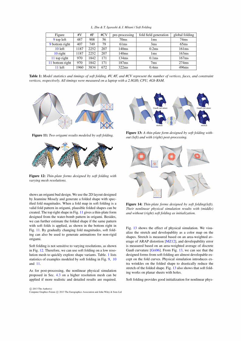
4.2. Global Folding
The proposed system defines a local folding operation Fαi,θi
for each vertex i. In our discrete setting, we use the one-ringneighborhood of vertex i as the domain of the fold operationFαi,θi . The image of Fαi,θi is called the local fold of vertexi. Note that fold directions are not required to be alignedwith mesh edges. The meshed structure is only used to findneighboring vertices, whose geometry is transformed by lo-cal folding and used to reconstruct their global position.
The objective at this stage is to find a shape such that for eachvertex i, its neighborhood approximates its local fold. Thisis a local-to-global deformation problem. We adapt LRIC-based mesh deformation [LSLCO05] to efficiently assemblethe local folds for a global folding. Fig. 8 illustrates globalfolding.
0
1
12
2
3
2
3
4
0
1
2
34
local fold #1 local fold #2 local fold #3
matching
region
global fold matching region
i j
i j
fit
Rij
CiCj
ijR Cj
(a) (b)
Figure 8: Global folding. (a) A 2D illustration. (b) Locallyassembling two 3D local folds. The overlapped wedge region(shown in pink) fits two neighboring local folds.
Global folding involves two steps: encoding and reconstruc-tion. Suppose each vertex vi is equipped with a frame Ci =(Xi,Yi,Zi). Let vi and Ci denote its position and frame onthe rest shape. In [LSLCO05], surface geometry is first lo-cally encoded into relative local coordinates ci j and relativerotations Qi j of neighboring frames, s.t vi − v j = C jci j andCiQi j = C j. In the reconstruction step, after the user speci-fy positions and frames of several fixed vertices, the systemsuccessively solves linear equations CiQi j = C j for framesand vi−v j =C jci j for positions of free vertices. In our glob-al folding stage, we particularly adapt the encoding step. Lo-cal folds are used in our system. Assume the folding opera-tion on vertex i is Fi, the encoded local coordinates are com-puted as ci j = CT
j (Fj(vi)− v j). For computing relative rota-tions, we first locally assemble neighboring folded patches,as shown in Fig. 8b. Specifically, shape matching from theoverlapped wedge region in the local fold of vertex j to thelocal fold of vertex i is applied, see [MHTG05] for moredetails on the shape-matching operation. After the best-fitrotation matrix Ri j is obtained, relative rotations are com-puted as Qi j = CT
i Ri jC j. While folding planar shapes, wesimply set frame Ci on the rest planar shape to be the iden-tity matrix. Therefore, Qi j = Ri j . Note that Qi j = QT
ji doesnot always holds, since the folding operations Fi and Fj maybe different.
Because we globally solve for the folded geometry, the user-defined magnitude and sharpness may not exactly matchwith the folds appearing in the final 3D geometry. Complexinteractions occur among all of the fold hints.
Implementation Details In the reconstruction step of glob-al folding, we can obtain the folded geometry by solving t-wo sparse linear systems. Given that the sparse matrix in thevertex-solving step (solve vi −v j =C jci j for all vertices) iscomputed from the triangulation of the rest shape, we canpre-compute its inverse after meshing. As for the matrix inthe frame-solving step (solve CiQi j = C j for all frames), itssparse structure is only dependent on the triangulation, whileits nonzero entry is computed from the fold field. Therefore,we can pre-compute its symbolic factorization after mesh-ing, which is reused to accelerate the numerical factorization
c⃝ 2013 The Author(s)Computer Graphics Forum c⃝ 2013 The Eurographics Association and John Wiley & Sons Ltd
L. Zhu & T. Igarashi & J. Mitani / Soft Folding
when the fold parameters are adjusted. We also fix the posi-tion and frame of the vertex at the center of the material inglobal folding and eliminate it from linear systems to makethem have unique least-square solutions.
Intersected Fold Hints When two or more foldhints intersect at vertex v, we make an infinite s-mall hole around this vertex, as show in the inset.
f1 f2
v
f1 f2v1 v2v3v4v5
v6
A similar method is used in[AJC11]. Assume the degree ofvertex v is d after meshing. We du-plicate the intersected vertex intod copies and add d virtual edges(shown in grey). After this dupli-cation, they will have unique fold-ing operations according to theirown fold hints. In the global foldingstage, though the duplicated ver-tices share the same geometry inthe rest sheet, they may have differ-ent frames and folded positions since they do not share thesame neighbors. We average the positions of those duplicat-ed vertices as the position of v after global folding.
4.3. Post-processing
A notable characteristic of physical developable surface be-havior is stress concentration. High stress appears at verylimited regions and exhibits fold lines. Our algorithm is es-sentially a diffusion process and cannot produce new stressconcentration, which might be inaccurate if we see it as aphysical simulation process. However, in our framework, weexpect that users explicitly specify stress concentration asfold lines. So it is desirable not to produce new stress con-centration in other places if we see it as a design tool.
If users need to obtain more realistic results, an optionalphysical simulation can be applied as a post-processing step.However, it is not trivial to compute forces that can repro-duce user-specified folds. Therefore, we developed a variantof physical simulation based on shape matching [MHTG05]to refine the folded shape. Simply applying a simulationbased on shape matching will make the folded result flat a-gain. Our solution is to reuse the local fold derived from thefold field as the rest shape. Specifically, we minimize
∑k
∑i∈N(k)
||vi −RkFk(vi)||2,
where N(k) is the one-ring neighborhood of vertex k, Rk isthe best transformation which fits the local fold of N(k) toits deformed shape, and FK is the folding operation at vertexk. We use standard dynamics in [MHTG05] to optimize thisnonlinear energy.
Note that the physical simulation is nonlinear and too slowto globally fold a planar sheet from the beginning. It iter-atively updates vertex positions by computing local forces
Figure 9: Top row: From left to right, thin plate forms fromincreased fold magnitudes. Bottom row: From left to right,thin plate forms (inspired by David Huffman’s design) fromdecreased fold sharpness.
Figure 10: Folding sheets with different materials can bemodeled by varying fold sharpness.
and it takes time to obtain a folded shape especially whenthe fold magnitude is large. We therefore use a linear geo-metric algorithm to quickly obtain a good approximation ofthe globally folded shape to support interactive explorationof thin-plate forms. A physical simulation can be completedat a higher resolution to optimize the result when users aresatisfied with the designed form.
5. Results
We show thin-plate forms designed by soft folding in thissection. Subfigures embedded in each figure visualize the in-put fold maps. Note that traditional click-and-drag interfaceis ineffective to model most of these shapes.
5.1. Experimental Results and Comparisons
Both straight folds and curved folds that are either soft orsharp are supported by soft folding, as shown in Fig. 9. Be-sides, users can interactively explore thin-plate forms’ vari-ants by adjusting fold magnitude (Fig. 9 top) or fold sharp-ness (Fig. 9 bottom).
Fig. 10 shows an example with intersected fold hints. Byconstraining maximum fold sharpness, soft folding can beused to design shapes with materials that are hard to bend.
Traditional origami intensively studies fold patterns’ layout.In addition to their layouts, soft folding also provides an in-teractive tool for studying fold angles in origami. Fig. 11 left
c⃝ 2013 The Author(s)Computer Graphics Forum c⃝ 2013 The Eurographics Association and John Wiley & Sons Ltd
L. Zhu & T. Igarashi & J. Mitani / Soft Folding
Figure #V #F #CV pre-processing fold field generation global folding9 top left 487 908 56 70ms 1ms 74ms
9 bottom right 407 749 79 61ms 3ms 65ms10 left 1187 2252 207 140ms 0.2ms 161ms
10 right 1187 2252 207 140ms 1ms 163ms11 top right 970 1842 171 134ms 0.1ms 167ms
11 bottom right 970 1842 171 187ms 7ms 274ms11 left 1960 3834 672 322ms 0.4ms 496ms
Table 1: Model statistics and timings of soft folding. #V, #F, and #CV represent the number of vertices, faces, and constraintvertices, respectively. All timings were measured on a laptop with a 2.8GHz CPU, 4Gb RAM.
Figure 11: Two origami results modeled by soft folding.
Figure 12: Thin-plate forms designed by soft folding withvarying mesh resolutions.
shows an origami bud design. We use the 2D layout designedby Jeannine Mosely and generate a folded shape with spec-ified fold magnitudes. When a fold map in soft folding is avalid fold pattern in origami, plausible folded shapes can becreated. The top right shape in Fig. 11 gives a thin-plate formdesigned from the water-bomb pattern in origami. Besides,we can further estimate the folded shape if the same patternwith soft folds is applied, as shown in the bottom right inFig. 11. By gradually changing fold magnitudes, soft fold-ing can also be used to generate animations for non-rigidorigami.
Soft folding is not sensitive to varying resolutions, as shownin Fig. 12. Therefore, we can use soft folding on a low reso-lution mesh to quickly explore shape variants. Table. 1 listsstatistics of examples modeled by soft folding in Fig. 9, 10and 11.
As for post-processing, the nonlinear physical simulationproposed in Sec. 4.3 on a higher resolution mesh can beapplied if more realistic and detailed results are required.
Gauß curvature Gauß curvature
stretch stretch
GaGaGa
Figure 13: A thin-plate form designed by soft folding with-out (left) and with (right) post-processing.
Figure 14: Thin-plate forms designed by soft folding(left).Their nonlinear physical simulation results with (middle)and without (right) soft folding as initialization.
Fig. 13 shows the effect of physical simulation. We visu-alize the stretch and developablity as a color map on theshapes. Stretch is measured based on an area-weighted av-erage of ARAP distortion [MZ12], and developability erroris measured based on an area-weighted average of discreteGauß curvature [Gri06]. From Fig. 13, we can see that thedesigned forms from soft folding are almost developable ex-cept on the fold curves. Physical simulation introduces ex-tra wrinkles on the folded shape to drastically reduce thestretch of the folded shape. Fig. 13 also shows that soft fold-ing works on planar sheets with holes.
Soft folding provides good initialization for nonlinear phys-
c⃝ 2013 The Author(s)Computer Graphics Forum c⃝ 2013 The Eurographics Association and John Wiley & Sons Ltd
L. Zhu & T. Igarashi & J. Mitani / Soft Folding
Figure #V #F #CV averK maxK averS maxS timing13 926 1725 116 6.3e-3(5.2e-3) 0.12(0.11) 3.9e-4(0.9e-3) 6.0e-3(1.4e-1) 4.0s
14 top 520 953 71 2.4e-2(5.2e-2) 0.38(0.92) 2.28e-3(3.75e-2) 7.9e-2(2.4e-1) 1.7s14 bottom 2471 4697 511 9.1e-3(1.0e-2) 0.23(0.26) 5.1e-4(6.0e-3) 1.8e-2(8.2e-1) 8.3s
Table 2: Statistics of post-processing. Average absolute Guaß curvature(averK), maximum absolute Guaß curvature(maxK),average stretch(averS) and maximum sketch(maxS) after and before(data in bracket) post-processing are given. Timings forpost-processing are measured in seconds.
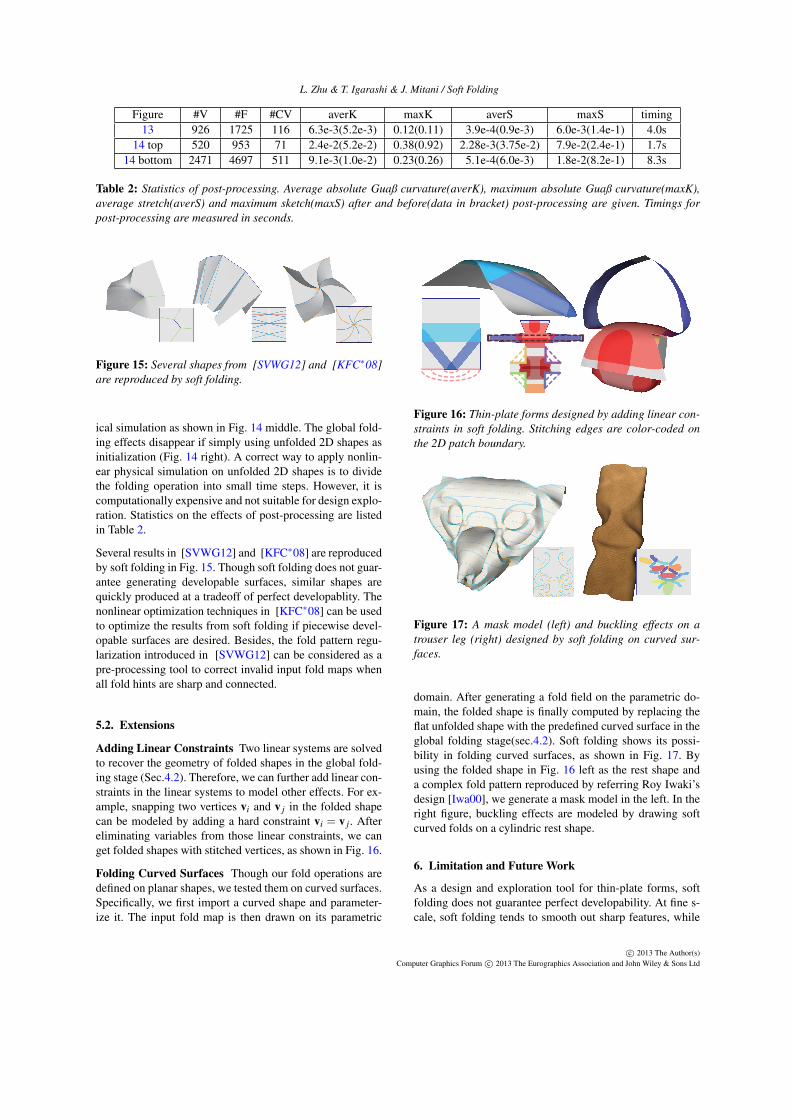
Figure 15: Several shapes from [SVWG12] and [KFC∗08]are reproduced by soft folding.
ical simulation as shown in Fig. 14 middle. The global fold-ing effects disappear if simply using unfolded 2D shapes asinitialization (Fig. 14 right). A correct way to apply nonlin-ear physical simulation on unfolded 2D shapes is to dividethe folding operation into small time steps. However, it iscomputationally expensive and not suitable for design explo-ration. Statistics on the effects of post-processing are listedin Table 2.
Several results in [SVWG12] and [KFC∗08] are reproducedby soft folding in Fig. 15. Though soft folding does not guar-antee generating developable surfaces, similar shapes arequickly produced at a tradeoff of perfect developablity. Thenonlinear optimization techniques in [KFC∗08] can be usedto optimize the results from soft folding if piecewise devel-opable surfaces are desired. Besides, the fold pattern regu-larization introduced in [SVWG12] can be considered as apre-processing tool to correct invalid input fold maps whenall fold hints are sharp and connected.
5.2. Extensions
Adding Linear Constraints Two linear systems are solvedto recover the geometry of folded shapes in the global fold-ing stage (Sec.4.2). Therefore, we can further add linear con-straints in the linear systems to model other effects. For ex-ample, snapping two vertices vi and v j in the folded shapecan be modeled by adding a hard constraint vi = v j. Aftereliminating variables from those linear constraints, we canget folded shapes with stitched vertices, as shown in Fig. 16.
Folding Curved Surfaces Though our fold operations aredefined on planar shapes, we tested them on curved surfaces.Specifically, we first import a curved shape and parameter-ize it. The input fold map is then drawn on its parametric
Figure 16: Thin-plate forms designed by adding linear con-straints in soft folding. Stitching edges are color-coded onthe 2D patch boundary.
Figure 17: A mask model (left) and buckling effects on atrouser leg (right) designed by soft folding on curved sur-faces.
domain. After generating a fold field on the parametric do-main, the folded shape is finally computed by replacing theflat unfolded shape with the predefined curved surface in theglobal folding stage(sec.4.2). Soft folding shows its possi-bility in folding curved surfaces, as shown in Fig. 17. Byusing the folded shape in Fig. 16 left as the rest shape anda complex fold pattern reproduced by referring Roy Iwaki’sdesign [Iwa00], we generate a mask model in the left. In theright figure, buckling effects are modeled by drawing softcurved folds on a cylindric rest shape.
6. Limitation and Future Work
As a design and exploration tool for thin-plate forms, softfolding does not guarantee perfect developability. At fine s-cale, soft folding tends to smooth out sharp features, while
c⃝ 2013 The Author(s)Computer Graphics Forum c⃝ 2013 The Eurographics Association and John Wiley & Sons Ltd
L. Zhu & T. Igarashi & J. Mitani / Soft Folding
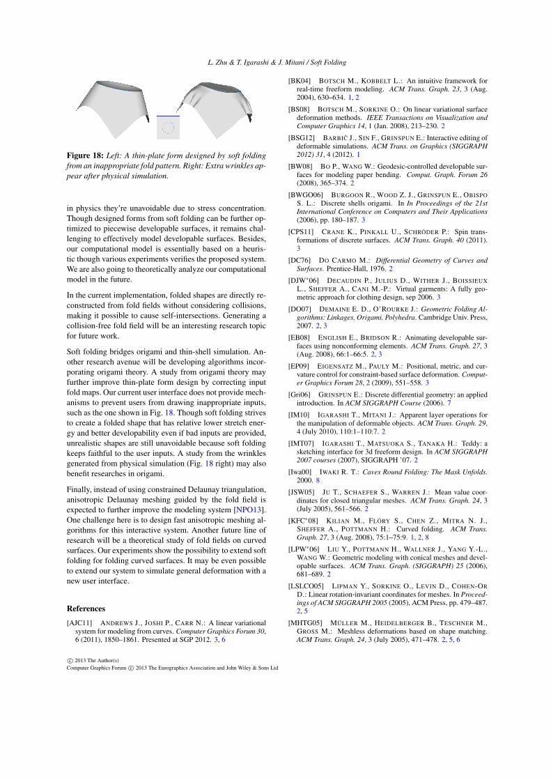
Figure 18: Left: A thin-plate form designed by soft foldingfrom an inappropriate fold pattern. Right: Extra wrinkles ap-pear after physical simulation.
in physics they’re unavoidable due to stress concentration.Though designed forms from soft folding can be further op-timized to piecewise developable surfaces, it remains chal-lenging to effectively model developable surfaces. Besides,our computational model is essentially based on a heuris-tic though various experiments verifies the proposed system.We are also going to theoretically analyze our computationalmodel in the future.
In the current implementation, folded shapes are directly re-constructed from fold fields without considering collisions,making it possible to cause self-intersections. Generating acollision-free fold field will be an interesting research topicfor future work.
Soft folding bridges origami and thin-shell simulation. An-other research avenue will be developing algorithms incor-porating origami theory. A study from origami theory mayfurther improve thin-plate form design by correcting inputfold maps. Our current user interface does not provide mech-anisms to prevent users from drawing inappropriate inputs,such as the one shown in Fig. 18. Though soft folding strivesto create a folded shape that has relative lower stretch ener-gy and better developability even if bad inputs are provided,unrealistic shapes are still unavoidable because soft foldingkeeps faithful to the user inputs. A study from the wrinklesgenerated from physical simulation (Fig. 18 right) may alsobenefit researches in origami.
Finally, instead of using constrained Delaunay triangulation,anisotropic Delaunay meshing guided by the fold field isexpected to further improve the modeling system [NPO13].One challenge here is to design fast anisotropic meshing al-gorithms for this interactive system. Another future line ofresearch will be a theoretical study of fold fields on curvedsurfaces. Our experiments show the possibility to extend softfolding for folding curved surfaces. It may be even possibleto extend our system to simulate general deformation with anew user interface.
References
[AJC11] ANDREWS J., JOSHI P., CARR N.: A linear variationalsystem for modeling from curves. Computer Graphics Forum 30,6 (2011), 1850–1861. Presented at SGP 2012. 3, 6
[BK04] BOTSCH M., KOBBELT L.: An intuitive framework forreal-time freeform modeling. ACM Trans. Graph. 23, 3 (Aug.2004), 630–634. 1, 2
[BS08] BOTSCH M., SORKINE O.: On linear variational surfacedeformation methods. IEEE Transactions on Visualization andComputer Graphics 14, 1 (Jan. 2008), 213–230. 2
[BSG12] BARBIC J., SIN F., GRINSPUN E.: Interactive editing ofdeformable simulations. ACM Trans. on Graphics (SIGGRAPH2012) 31, 4 (2012). 1
[BW08] BO P., WANG W.: Geodesic-controlled developable sur-faces for modeling paper bending. Comput. Graph. Forum 26(2008), 365–374. 2
[BWGO06] BURGOON R., WOOD Z. J., GRINSPUN E., OBISPOS. L.: Discrete shells origami. In In Proceedings of the 21stInternational Conference on Computers and Their Applications(2006), pp. 180–187. 3
[CPS11] CRANE K., PINKALL U., SCHRÖDER P.: Spin trans-formations of discrete surfaces. ACM Trans. Graph. 40 (2011).3
[DC76] DO CARMO M.: Differential Geometry of Curves andSurfaces. Prentice-Hall, 1976. 2
[DJW∗06] DECAUDIN P., JULIUS D., WITHER J., BOISSIEUXL., SHEFFER A., CANI M.-P.: Virtual garments: A fully geo-metric approach for clothing design, sep 2006. 3
[DO07] DEMAINE E. D., O’ROURKE J.: Geometric Folding Al-gorithms: Linkages, Origami, Polyhedra. Cambridge Univ. Press,2007. 2, 3
[EB08] ENGLISH E., BRIDSON R.: Animating developable sur-faces using nonconforming elements. ACM Trans. Graph. 27, 3(Aug. 2008), 66:1–66:5. 2, 3
[EP09] EIGENSATZ M., PAULY M.: Positional, metric, and cur-vature control for constraint-based surface deformation. Comput-er Graphics Forum 28, 2 (2009), 551–558. 3
[Gri06] GRINSPUN E.: Discrete differential geometry: an appliedintroduction. In ACM SIGGRAPH Course (2006). 7
[IM10] IGARASHI T., MITANI J.: Apparent layer operations forthe manipulation of deformable objects. ACM Trans. Graph. 29,4 (July 2010), 110:1–110:7. 2
[IMT07] IGARASHI T., MATSUOKA S., TANAKA H.: Teddy: asketching interface for 3d freeform design. In ACM SIGGRAPH2007 courses (2007), SIGGRAPH ’07. 2
[Iwa00] IWAKI R. T.: Cavex Round Folding: The Mask Unfolds.2000. 8
[JSW05] JU T., SCHAEFER S., WARREN J.: Mean value coor-dinates for closed triangular meshes. ACM Trans. Graph. 24, 3(July 2005), 561–566. 2
[KFC∗08] KILIAN M., FLÖRY S., CHEN Z., MITRA N. J.,SHEFFER A., POTTMANN H.: Curved folding. ACM Trans.Graph. 27, 3 (Aug. 2008), 75:1–75:9. 1, 2, 8
[LPW∗06] LIU Y., POTTMANN H., WALLNER J., YANG Y.-L.,WANG W.: Geometric modeling with conical meshes and devel-opable surfaces. ACM Trans. Graph. (SIGGRAPH) 25 (2006),681–689. 2
[LSLCO05] LIPMAN Y., SORKINE O., LEVIN D., COHEN-ORD.: Linear rotation-invariant coordinates for meshes. In Proceed-ings of ACM SIGGRAPH 2005 (2005), ACM Press, pp. 479–487.2, 5
[MHTG05] MÜLLER M., HEIDELBERGER B., TESCHNER M.,GROSS M.: Meshless deformations based on shape matching.ACM Trans. Graph. 24, 3 (July 2005), 471–478. 2, 5, 6
c⃝ 2013 The Author(s)Computer Graphics Forum c⃝ 2013 The Eurographics Association and John Wiley & Sons Ltd
L. Zhu & T. Igarashi & J. Mitani / Soft Folding
[MZ12] MYLES A., ZORIN D.: Global parametrization by incre-mental flattening. ACM Trans. Graph. 31, 4 (July 2012), 109:1–109:11. 7
[NPO13] NARAIN R., PFAFF T., O’BRIEN J. F.: Folding andcrumpling adaptive sheets. ACM Transactions on Graphics 32, 4(July 2013). Proceedings of ACM SIGGRAPH 2013, Anaheim.3, 9
[PF95] POTTMANN H., FARIN G. E.: Developable rational bézi-er and b-spline surfaces. Computer Aided Geometric Design 12,5 (1995), 513 –531. 2
[PHD∗10] POTTMANN H., HUANG Q., DENG B., SCHIFTNERA., KILIAN M., GUIBAS L., WALLNER J.: Geodesic patterns.In ACM SIGGRAPH 2010 papers (New York, NY, USA, 2010),SIGGRAPH ’10, ACM, pp. 43:1–43:10. 2
[PIX] PIXOLOGIC: Zbrush. http: //www.pixologic.com . 2
[RPC∗10] ROHMER D., POPA T., CANI M.-P., HAHMANN S.,SHEFFER A.: Animation wrinkling: augmenting coarse clothsimulations with realistic-looking wrinkles. ACM Trans. Graph.29, 6 (Dec. 2010), 157:1–157:8. 3
[RSW∗07] ROSE K., SHEFFER A., WITHER J., CANI M.-P.,THIBERT B.: Developable surfaces from arbitrary sketchedboundaries, 2007. 2
[SA07] SORKINE O., ALEXA M.: As-rigid-as-possible sur-face modeling. In Proceedings of EUROGRAPHICS/ACM SIG-GRAPH Symposium on Geometry Processing (2007), pp. 109–116. 3
[SVWG12] SOLOMON J., VOUGA E., WARDETZKY M., GRIN-SPUN E.: Flexible developable surfaces. Comp. Graph. Forum31, 5 (Aug. 2012), 1567–1576. 2, 8
[UIM12] UMETANI N., IGARASHI T., MITRA N. J.: Guided ex-ploration of physically valid shapes for furniture design. ACMTrans. Graph. 31, 4 (July 2012), 86:1–86:11. 2
[Wan08] WANG C. C. L.: Towards flattenable mesh surfaces.Comput. Aided Des. 40, 1 (2008), 109–122. 2
[WDAH10] WINKLER T., DRIESEBERG J., ALEXA M., HOR-MANN K.: Multi-scale geometry interpolation. Computer Graph-ics Forum 29, 2 (May 2010), 309–318. 3
[YBS07] YOSHIZAWA S., BELYAEV A. G., SEIDEL H.-P.:Skeleton-based variational mesh deformations. ComputerGraphics Forum 26, 3 (2007), 255–264. EUROGRAPHICS’07.2
[YYPM11] YANG Y.-L., YANG Y.-J., POTTMANN H., MITRAN. J.: Shape space exploration of constrained meshes. In Pro-ceedings of the 2011 SIGGRAPH Asia Conference (New York,NY, USA, 2011), SA ’11, ACM, pp. 124:1–124:12. 2
Appendix A:
Here we derive the fold difference of two folding operationsFα,θ and Fα,θ on vertex v. We make a disk centered at v asthe domain D of the folding operations. Using a polar coor-dinate system with v as its origin, the folded shape Sα,θ (r,β )from Fα,θ has a parametric form
Sα,θ (r,β ) = r
cosα cos(β −α)− sinα sin(β −α)cosθsinα cos(β −α)+ cosα sin(β −α)cosθ
|sin(β −α)|sinθ
Considering a neighboring patch with radius ε , the L2 dis-tance between Sα,θ (r,β ) and Sα,θ (r,β ) is∫ π
−π
∫ ε
0||Sα,θ (r,β )−Sα,θ (r,β )||
2drdβ .
Substituting the parametric equation of Sα,θ (r,β ), this L2
distance can be represented in an explicit form
43
ε3d(
Fα,θ ,Fα,θ
)where d(Fα,θ ,Fα,θ ) is written in Eqn. 1.
Having got the formulation Eqn. 1, the following propertiesof our proposed formulations for fold difference and foldsummation can be verified:
• d(Fα,θ ,Fα,θ ) ≥ 0. when θ = 0, d(Fα,θ , Fα,θ ) = 0 if andonly if α = α and θ = θ .
• d(Fα,θ ,Fα,θ ) is independent of α and α when θ = 0.
• When α = α , it is true that Fα,θ + Fα,θ = Fα,(θ+θ)/2;When θ = 0, Fα,θ +Fα,0 = Fα,θ/2 holds.
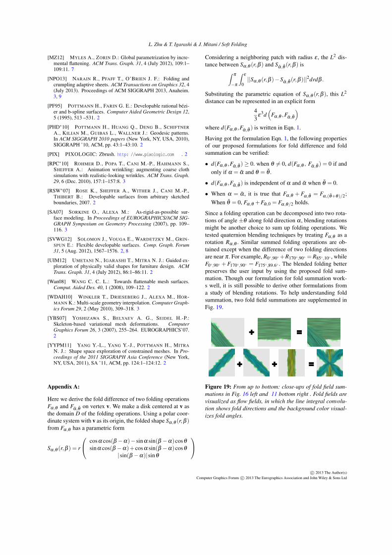
Since a folding operation can be decomposed into two rota-tions of angle ±θ along fold direction α , blending rotationsmight be another choice to sum up folding operations. Wetested quaternion blending techniques by treating Fα,θ as arotation Rα,θ . Similar summed folding operations are ob-tained except when the difference of two folding directionsare near π . For example, R0◦,90◦ +R170◦,90◦ = R85◦,10◦ , whileF0◦,90◦ +F170◦,90◦ = F175◦,89.6◦ . The blended folding betterpreserves the user input by using the proposed fold sum-mation. Though our formulation for fold summation work-s well, it is still possible to derive other formulations froma study of blending rotations. To help understanding foldsummation, two fold field summations are supplemented inFig. 19.
+
+ +
=
=
Figure 19: From up to bottom: close-ups of fold field sum-mations in Fig. 16 left and 11 bottom right . Fold fields arevisualized as flow fields, in which the line integral convolu-tion shows fold directions and the background color visual-izes fold angles.
c⃝ 2013 The Author(s)Computer Graphics Forum c⃝ 2013 The Eurographics Association and John Wiley & Sons Ltd