Embed Size (px)
Citation preview
Soft-Close Pullout with Ball Bearing Tri-Slide
PARTS LIST:PULLOUT CHASSIS
(4) #6 X ½” FLAT HEAD SCREWS(4) #8 X 3⁄4” DEEP THREAD SCREWS
(2) #6 X 1” FLAT HEAD SCREWSADJUSTABLE RUB BUSHING KIT
(2) DOOR BUMPERS
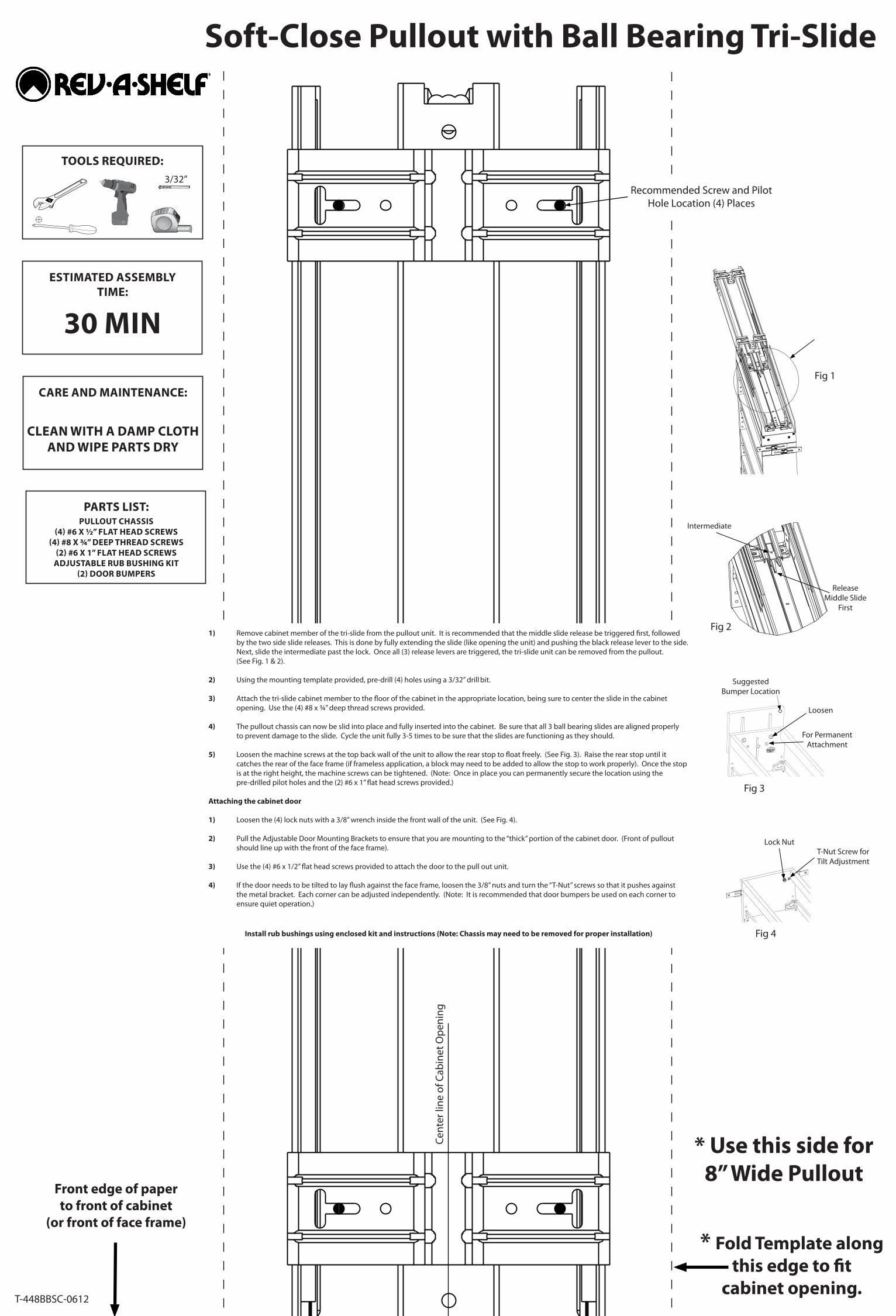
Recommended Screw and Pilot Hole Location (4) Places
T-448BBSC-0612
Cent
er li
ne o
f Cab
inet
Ope
ning
* Fold Template alongthis edge to fit
cabinet opening.
* Use this side for8” Wide Pullout
Front edge of paper to front of cabinet
(or front of face frame)
1) Remove cabinet member of the tri-slide from the pullout unit. It is recommended that the middle slide release be triggered first, followed by the two side slide releases. This is done by fully extending the slide (like opening the unit) and pushing the black release lever to the side. Next, slide the intermediate past the lock. Once all (3) release levers are triggered, the tri-slide unit can be removed from the pullout. (See Fig. 1 & 2).
2) Using the mounting template provided, pre-drill (4) holes using a 3/32” drill bit.
3) Attach the tri-slide cabinet member to the floor of the cabinet in the appropriate location, being sure to center the slide in the cabinet opening. Use the (4) #8 x ¾” deep thread screws provided.
4) The pullout chassis can now be slid into place and fully inserted into the cabinet. Be sure that all 3 ball bearing slides are aligned properly to prevent damage to the slide. Cycle the unit fully 3-5 times to be sure that the slides are functioning as they should.
5) Loosen the machine screws at the top back wall of the unit to allow the rear stop to float freely. (See Fig. 3). Raise the rear stop until it catches the rear of the face frame (if frameless application, a block may need to be added to allow the stop to work properly). Once the stop is at the right height, the machine screws can be tightened. (Note: Once in place you can permanently secure the location using the pre-drilled pilot holes and the (2) #6 x 1” flat head screws provided.)
Attaching the cabinet door
1) Loosen the (4) lock nuts with a 3/8” wrench inside the front wall of the unit. (See Fig. 4).
2) Pull the Adjustable Door Mounting Brackets to ensure that you are mounting to the “thick” portion of the cabinet door. (Front of pullout should line up with the front of the face frame).
3) Use the (4) #6 x 1/2” flat head screws provided to attach the door to the pull out unit.
4) If the door needs to be tilted to lay flush against the face frame, loosen the 3/8” nuts and turn the “T-Nut” screws so that it pushes against the metal bracket. Each corner can be adjusted independently. (Note: It is recommended that door bumpers be used on each corner to ensure quiet operation.)
Install rub bushings using enclosed kit and instructions (Note: Chassis may need to be removed for proper installation)
TOOLS REQUIRED:
ESTIMATED ASSEMBLY TIME:
30 MIN
CARE AND MAINTENANCE:
CLEAN WITH A DAMP CLOTH AND WIPE PARTS DRY
3/32”
Fig 1
Fig 3
Loosen
For Permanent Attachment
Suggested Bumper Location
Fig 4
T-Nut Screw for Tilt Adjustment
Lock Nut
Fig 2
Intermediate
Release Middle Slide
First
Cent
er li
ne o
f Cab
inet
Ope
ning
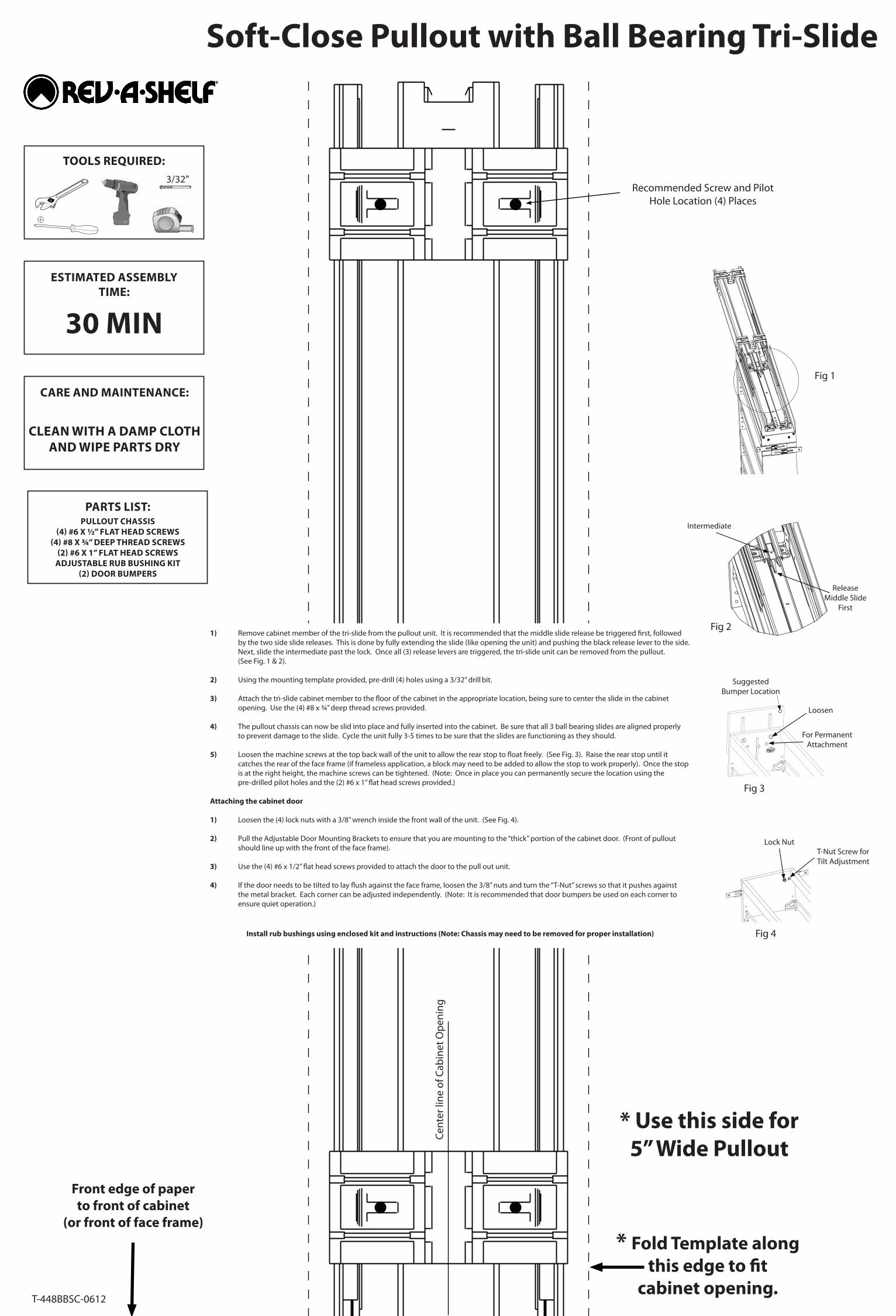
* Use this side for5” Wide Pullout
Recommended Screw and Pilot Hole Location (4) Places
Fig 1
Fig 3
Loosen
For Permanent Attachment
Suggested Bumper Location
Fig 4
T-Nut Screw for Tilt Adjustment
Lock Nut
Fig 2
Intermediate
Release Middle Slide
First
Soft-Close Pullout with Ball Bearing Tri-Slide
PARTS LIST:PULLOUT CHASSIS
(4) #6 X ½” FLAT HEAD SCREWS(4) #8 X 3⁄4” DEEP THREAD SCREWS
(2) #6 X 1” FLAT HEAD SCREWSADJUSTABLE RUB BUSHING KIT
(2) DOOR BUMPERS
TOOLS REQUIRED:
ESTIMATED ASSEMBLY TIME:
30 MIN
CARE AND MAINTENANCE:
CLEAN WITH A DAMP CLOTH AND WIPE PARTS DRY
3/32”
1) Remove cabinet member of the tri-slide from the pullout unit. It is recommended that the middle slide release be triggered first, followedby the two side slide releases. This is done by fully extending the slide (like opening the unit) and pushing the black release lever to the side.Next, slide the intermediate past the lock. Once all (3) release levers are triggered, the tri-slide unit can be removed from the pullout.(See Fig. 1 & 2).
2) Using the mounting template provided, pre-drill (4) holes using a 3/32” drill bit.
3) Attach the tri-slide cabinet member to the floor of the cabinet in the appropriate location, being sure to center the slide in the cabinetopening. Use the (4) #8 x ¾” deep thread screws provided.
4) The pullout chassis can now be slid into place and fully inserted into the cabinet. Be sure that all 3 ball bearing slides are aligned properlyto prevent damage to the slide. Cycle the unit fully 3-5 times to be sure that the slides are functioning as they should.
5) Loosen the machine screws at the top back wall of the unit to allow the rear stop to float freely. (See Fig. 3). Raise the rear stop until itcatches the rear of the face frame (if frameless application, a block may need to be added to allow the stop to work properly). Once the stopis at the right height, the machine screws can be tightened. (Note: Once in place you can permanently secure the location using thepre-drilled pilot holes and the (2) #6 x 1” flat head screws provided.)
Attaching the cabinet door
1) Loosen the (4) lock nuts with a 3/8” wrench inside the front wall of the unit. (See Fig. 4).
2) Pull the Adjustable Door Mounting Brackets to ensure that you are mounting to the “thick” portion of the cabinet door. (Front of pulloutshould line up with the front of the face frame).
3) Use the (4) #6 x 1/2” flat head screws provided to attach the door to the pull out unit.
4) If the door needs to be tilted to lay flush against the face frame, loosen the 3/8” nuts and turn the “T-Nut” screws so that it pushes againstthe metal bracket. Each corner can be adjusted independently. (Note: It is recommended that door bumpers be used on each corner toensure quiet operation.)
Install rub bushings using enclosed kit and instructions (Note: Chassis may need to be removed for proper installation)
T-448BBSC-0612
Front edge of paper to front of cabinet
(or front of face frame)
* Fold Template alongthis edge to fit
cabinet opening.