Embed Size (px)
Citation preview

SUPRA Surface Mount Integrated System
BEFORE YOU START
PLANNING THE INSTALLATION
www.Lumishore.com
45-0051-REV-2
Lumishore UK Unit 3, Technium 1, Kings Road, Swansea, SA1 8PH, UK | +44(0)208 144 1694 | [email protected]
Lumishore USA 7137 24TH Court East Sarasota, Florida 34234 | (941) 405-3302 | [email protected]
SMX 22, SMX52 & SMX 102 Installation and Operating Guide
Congratulations! You have purchased a LUMISHORE advanced LED technology underwater lighting system. Every care has been taken to ensure your SMX22, SMX52 or SMX102 SUPRA system arrives in perfect condition, so please enjoy the ultimate experience in underwater lighting.
Please read the following pages before attempting installation to ensure complete understanding of the LUMISHORE LED lights.
• High Intensity LED light – Do not stare into the LED module at close proximity.
• The lights are high power and should be installed below the water line.
• These lights are intended to be installed on vessels no larger than 50ft (15m).
• For best underwater illumination, LUMISHORE recommends installation 4” to 12” (100-300mm) below the min load water line.
• Choose a location - The light must be mounted on a �at (not curved) surface. Mount on transom or side of the hull only.
• A hole will be drilled to allow the cable to be inserted; care must be taken to ensure there is unrestricted access inside the hull.
• When installing three or more lights, equal spacing 2.5’- 3’ is recommended to give a consistent light pool.
• The light is temperature sensitive and must not be located close to the exhaust outlet or other heat source.
• The lights have a voltage rating of 10.5 - 31volts. Never connect to a voltage out of this range or direct to AC voltage.
• Each light must be individually Fused, To choose the correct fuse value for your light and voltage supply refer to the provided
fuse table in this manual.
• No chemical cleaners/chemical spray, sandblasting/pressure washing should be applied or used on lights. This will
negate warranty
The lights are very easy to install and operate. Follow the wiring diagram inside this guide
The following components should be used;
• Fuse (1 per light)
• Waterproof junction box
• Power Relay
• Switch or Lumi-Switch
• Power cable - See cable gauge guide for more
information
• Switch cable - 2 -Core (Min 24AWG) - 4-Core
for Lumi-Switch
The following tools will be required;
• Hand Drill
• Screwdriver (Cross head)
• Appropriate Sealant (e.g. 3M 4200)
• Cleaning rags
1
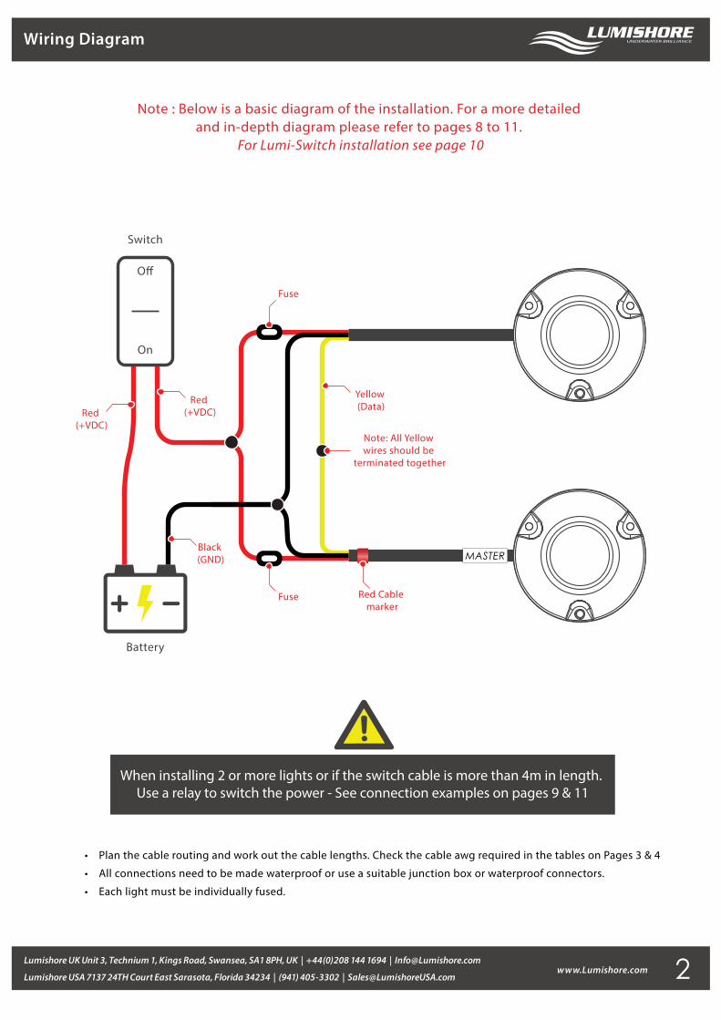
Wiring Diagram
www.Lumishore.comLumishore UK Unit 3, Technium 1, Kings Road, Swansea, SA1 8PH, UK | +44(0)208 144 1694 | [email protected]
Lumishore USA 7137 24TH Court East Sarasota, Florida 34234 | (941) 405-3302 | [email protected]
• Plan the cable routing and work out the cable lengths. Check the cable awg required in the tables on Pages 3 & 4
• All connections need to be made waterproof or use a suitable junction box or waterproof connectors.
• Each light must be individually fused.
When installing 2 or more lights or if the switch cable is more than 4m in length. Use a relay to switch the power - See connection examples on pages 9 & 11
Note : Below is a basic diagram of the installation. For a more detailed and in-depth diagram please refer to pages 8 to 11.
For Lumi-Switch installation see page 10
Battery
Switch
O�
On
Red (+VDC)
Red (+VDC)
Yellow (Data)
Black (GND)
Note: All Yellow wires should be
terminated together
Fuse
Fuse
MASTER
Red Cable marker
2
3www.Lumishore.comLumishore UK Unit 3, Technium 1, Kings Road, Swansea, SA1 8PH, UK | +44(0)208 144 1694 | [email protected]
Lumishore USA 7137 24TH Court East Sarasota, Florida 34234 | (941) 405-3302 | [email protected]
Cable Gauge Tables
15 f
t
10 f
t
20 f
t
25 f
t
30 f
t
40 f
t
50 f
t
60 f
t
70 f
t
80 f
t
90 f
t
100
ft
120
ft
130
ft
110
ft
0 to
6 f
t
CU
RR
EN
T F
LO
W I
N A
MP
S
Criti
cal
3% VOLT
AG
ED
ROP
16 AW
G
14 AW
G
12 AW
G
10 AW
G
8A
WG
6A
WG
2A
WG
4A
WG
6A
WG
8A
WG
10 AW
G
12 AW
G
14 AW
G
16 AW
G
2A
WG
4A
WG
6A
WG
8A
WG
10 AW
G
12 AW
G
14 AW
G
2A
WG
4A
WG
6A
WG
8A
WG
10 AW
G
12 AW
G
1A
WG
14 AW
G
2A
WG
4A
WG
6A
WG
1A
WG
0A
WG
8A
WG
10 AW
G
12 AW
G
2|0
AW
G
2A
WG
6A
WG
1A
WG
0A
WG
4A
WG
8A
WG
10 AW
G
3|0
AW
G
0A
WG
2|0
AW
G
1A
WG
2A
WG
4A
WG
6A
WG
8A
WG
3|0
AW
G
6A
WG
4|0
AW
G
2|0
AW
G
0A
WG
1A
WG
2A
WG
4A
WG
4|0
AW
G
3|0
AW
G
2|0
AW
G
0A
WG
1A
WG
2A
WG
4A
WG
6A
WG
8 4|0
AW
G
4A
WG
3|0
AW
G
2|0
AW
G
0A
WG
1A
WG
2A
WG
6A
WG
4A
WG
4|0
AW
G
3|0
AW
G
0A
WG
1A
WG
2A
WG
4|0
AW
G
3|0
AW
G
2|0
AW
G
0A
WG
1A
WG
2A
WG
4A
WG
4|0
AW
G
3|0
AW
G
2|0
AW
G
0A
WG
1A
WG
2A
WG
4A
WG
1A
WG
4|0
AW
G
3|0
AW
G
2|0
AW
G
0A
WG
4|0
AW
G
3|0
AW
G
2|0
AW
G
4|0
AW
G
3|0
AW
G
2|0
AW
G
0A
WG
12A
WG
AW
G
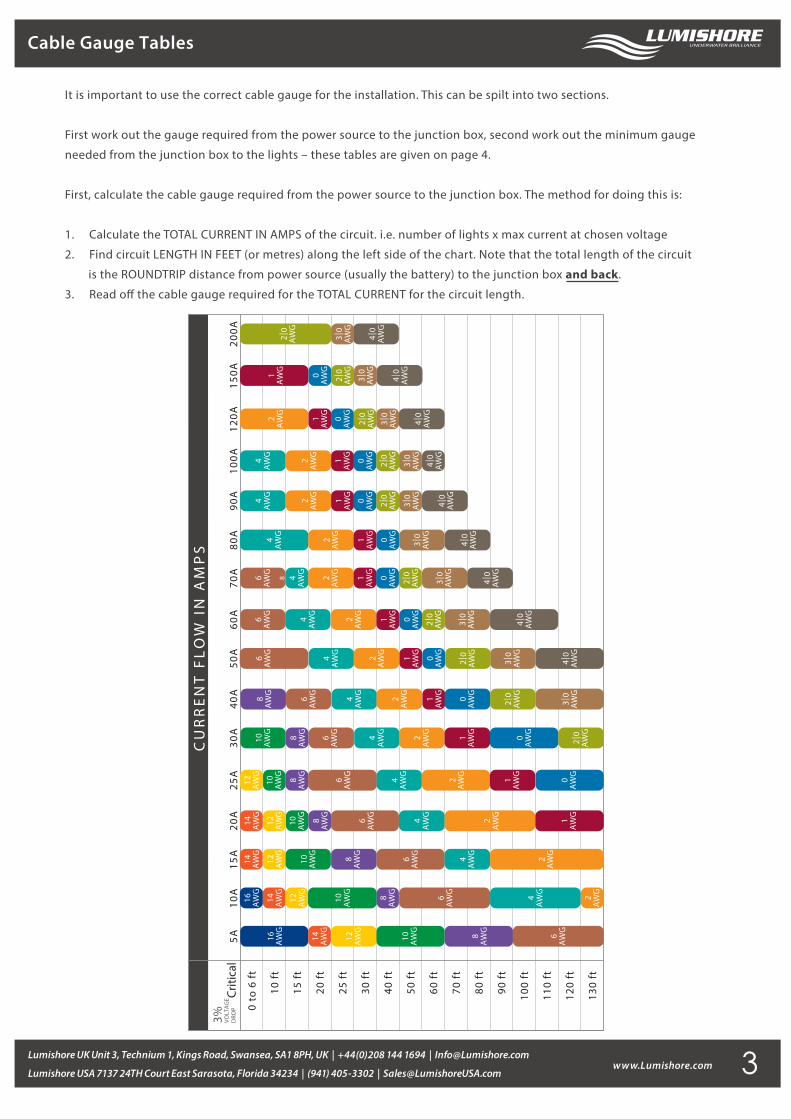
It is important to use the correct cable gauge for the installation. This can be spilt into two sections.
First work out the gauge required from the power source to the junction box, second work out the minimum gauge
needed from the junction box to the lights – these tables are given on page 4.
First, calculate the cable gauge required from the power source to the junction box. The method for doing this is:
1. Calculate the TOTAL CURRENT IN AMPS of the circuit. i.e. number of lights x max current at chosen voltage
2. Find circuit LENGTH IN FEET (or metres) along the left side of the chart. Note that the total length of the circuit
is the ROUNDTRIP distance from power source (usually the battery) to the junction box and back.
3. Read o� the cable gauge required for the TOTAL CURRENT for the circuit length.
3
www.Lumishore.comLumishore UK Unit 3, Technium 1, Kings Road, Swansea, SA1 8PH, UK | +44(0)208 144 1694 | [email protected]
Lumishore USA 7137 24TH Court East Sarasota, Florida 34234 | (941) 405-3302 | [email protected]
Cable Gauge Tables
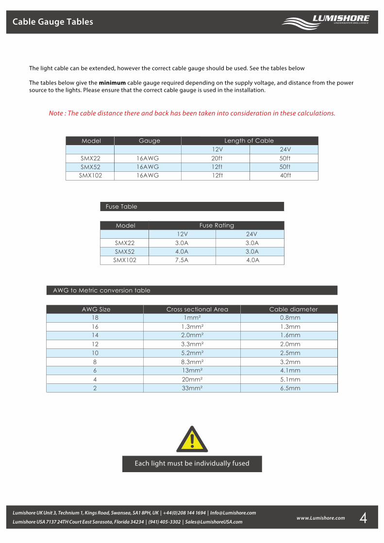
The light cable can be extended, however the correct cable gauge should be used. See the tables below
The tables below give the minimum cable gauge required depending on the supply voltage, and distance from the power source to the lights. Please ensure that the correct cable gauge is used in the installation.
Fuse Table
Model
SMX22SMX52
SMX102
12V3.0A4.0A
Fuse Rating24V3.0A3.0A
7.5A 4.0A
Model
SMX22SMX52
SMX102
16AWG16AWG
Gauge Length of Cable12V20ft12ft12ft16AWG
24V50ft50ft40ft
AWG to Metric conversion table
AWG Size Cross sectional Area Cable diameter
10864
18161412
2
5.2mm²8.3mm²13mm²20mm²
1mm²1.3mm²2.0mm²3.3mm²
33mm²
2.5mm3.2mm4.1mm5.1mm
0.8mm1.3mm1.6mm2.0mm
6.5mm
Each light must be individually fused
4
Note : The cable distance there and back has been taken into consideration in these calculations.
www.Lumishore.comLumishore UK Unit 3, Technium 1, Kings Road, Swansea, SA1 8PH, UK | +44(0)208 144 1694 | [email protected]
Lumishore USA 7137 24TH Court East Sarasota, Florida 34234 | (941) 405-3302 | [email protected]
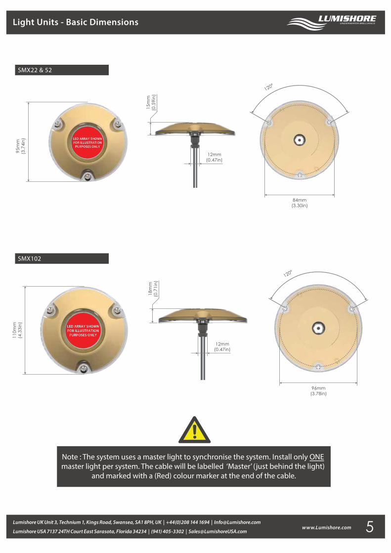
Light Units - Basic Dimensions
SMX22 & 52
12mm(0.47in)
15m
m(0
.59i
n)
95m
m(3
.74i
n)
84mm(3.30in)
120°
LED ARRAY SHOWN FOR ILLUSTRATION
PURPOSES ONLY
SMX102
96mm(3.78in)
120°
12mm(0.47in)
18m
m(0
.71i
n)
110m
m(4
.33i
n) LED ARRAY SHOWN FOR ILLUSTRATION
PURPOSES ONLY
Note : The system uses a master light to synchronise the system. Install only ONE master light per system. The cable will be labelled ‘Master’ (just behind the light)
and marked with a (Red) colour marker at the end of the cable.
5

www.Lumishore.comLumishore UK Unit 3, Technium 1, Kings Road, Swansea, SA1 8PH, UK | +44(0)208 144 1694 | [email protected]
Lumishore USA 7137 24TH Court East Sarasota, Florida 34234 | (941) 405-3302 | [email protected]
Light Installation
Tools Required
Drill/DriverPhillips ScrewdriverDrill Bits
(3.5mm & 13.5mm)Marine Sealant
(Use only 3M 4200)Rags for clean-up
Pilot Hole for Screws9/64” (3.5mm)
Hole for cable and cable gland17/32” (13.5mm)
1. Select a suitable �at surface that is accessible from inside the vessel and ensure the light cable can be run without a problem.
2. Check inside the hull to ensure there is clearance prior to drilling.
3. With one hole at the bottom centre (see image below), mark and drill the pilot holes for the screws. Drill the power cable hole.
The cable hole must be large enought to accept the cable gland on the back of the light, so that the light sits �ush.
4. Apply a continuous thick bead of sealant approximately 0.6” (15mm) from the edge of the light and around the cable.
Refer to the image above.
5. Push the power cable through the hole and align the light with the pilot hole screws.
6. Attach the light using the 3 stainless steel screws by hand tightening with a screwdriver.
Note : Cored hulls must be sealed prior to �tting the lights. Consult boat manufacturer for further information.
7. Use a damp cloth to wipe o� excess sealant. DO NOT USE CHEMICAL CLEANERS OR SOLVENTS!
8. Wire up lights - Refer to wiring diagrams on pages 9 to12 for more information. Note that each light must be individually fused.
IMPORTANT: REFER TO THE DIRECTIONS ON THE SEALANT TO MAKE SURE IT HAS
FULLY CURED BEFORE LAUNCHING THE BOAT INTO THE WATER.
Rear sideApply sealant
Bottom center
IMPORTANT: DO NOT OVER TIGHTEN.
DO NOT USE POWER TOOLS TO TIGHTEN SCREWS.
6
www.Lumishore.comLumishore UK Unit 3, Technium 1, Kings Road, Swansea, SA1 8PH, UK | +44(0)208 144 1694 | [email protected]
Lumishore USA 7137 24TH Court East Sarasota, Florida 34234 | (941) 405-3302 | [email protected]
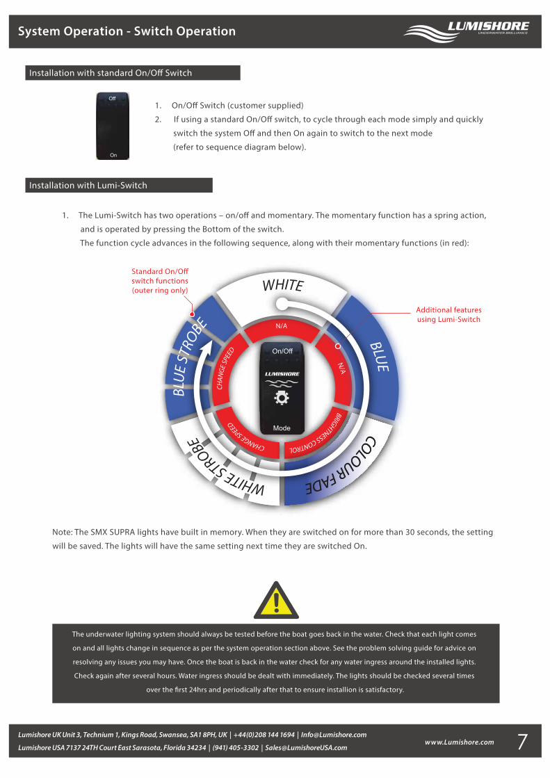
System Operation - Switch Operation
Note: The SMX SUPRA lights have built in memory. When they are switched on for more than 30 seconds, the setting
will be saved. The lights will have the same setting next time they are switched On.
1. On/O� Switch (customer supplied)
2. If using a standard On/O� switch, to cycle through each mode simply and quickly
switch the system O� and then On again to switch to the next mode
(refer to sequence diagram below).
Off
On
On/Off
Mode
WHITE
BLUECOLOUR FADE
COLOUR FADE
N/A
N/A
BRIGHTNESS CONTROLCHANGE SPEED
CHAN
GE SP
EED
Standard On/O�switch functions(outer ring only)
Additional featuresusing Lumi-Switch
1. The Lumi-Switch has two operations – on/o� and momentary. The momentary function has a spring action,
and is operated by pressing the Bottom of the switch.
The function cycle advances in the following sequence, along with their momentary functions (in red):
Installation with Lumi-Switch
Installation with standard On/O� Switch
The underwater lighting system should always be tested before the boat goes back in the water. Check that each light comes
on and all lights change in sequence as per the system operation section above. See the problem solving guide for advice on
resolving any issues you may have. Once the boat is back in the water check for any water ingress around the installed lights.
Check again after several hours. Water ingress should be dealt with immediately. The lights should be checked several times
over the �rst 24hrs and periodically after that to ensure installion is satisfactory.
7

www.Lumishore.comLumishore UK Unit 3, Technium 1, Kings Road, Swansea, SA1 8PH, UK | +44(0)208 144 1694 | [email protected]
Lumishore USA 7137 24TH Court East Sarasota, Florida 34234 | (941) 405-3302 | [email protected]
LUMISHORE lights require simple cleaning. Lights should be checked often to ensure the light body and lens area
are free from sea growth. In the event that your light requires cleaning, we recommend the use of a soft cloth or
soft bristled brush.
DO NOT use any abrasive cleaning materials as these may damage the body of the light.
DO NOT use any cleaning �uids that contain solvents, acids or alkalis.
DO NOT clean using pressure washing or sandblasting equipment.
Slight discolouration of body may occur over life. This does not a�ect performance, and is not subject to warranty.
Due to nature and high build quality it may on rare occasions be possible to see small levels of condensation,
this is normal for high power LEDs and will disappear after cooling and does not harm operation in any way.
No chemicals, cleaners, chemical sprays or sandblasting should ever be applied / used on lights — this will
negate warranty
If you have questions or comments, please e-mail [email protected] or call USA (941) 405-3302,
United Kingdom +44(0)208 144 1694, or France +33(0)493 582 537.
LUMISHORE Ltd warrants the SMX22, 52 & 102 to be free from defects in workmanship and materials for a period of
two years, starting from the date of original purchase. Misuse, abuse, improper installation, neglect, improper shipping,
damage caused by disasters such as �re, �ood, and lightning, installation by unquali�ed personnel, unauthorized repair
or modi�cation will void this warranty. For the avoidance of confusion and doubt, non-compliance with all installation,
maintenance and operating instructions in this document constitute non-conformance with warranty terms.
Full warranty details are available at www.lumishore.com
Maintenance and Cleaning
Product Support / Warranty
8
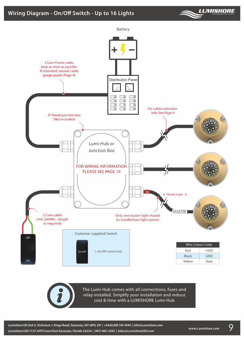
Wiring Diagram - On/O� Switch - Up to 16 Lights
www.Lumishore.comLumishore UK Unit 3, Technium 1, Kings Road, Swansea, SA1 8PH, UK | +44(0)208 144 1694 | [email protected]
Lumishore USA 7137 24TH Court East Sarasota, Florida 34234 | (941) 405-3302 | [email protected]
The Lumi-Hub comes with all connections, fuses andrelay installed. Simplify your installation and reduce
cost & time with a LUMISHORE Lumi-Hub
Distribution Panel
Battery
1, On/O� control only
Customer supplied Switch
Red
Black
+VDC
GND
Yellow Data
Wire Colour Code
FOR WIRING INFORMATIONPLEASE SEE PAGE 10
2 Core Power cablekeep as short as possible
If extended consult cablegauge guide (Page 4)
On
O�
IP Rated junction box(Not included)
2-Core cable(min 24AWG - length
as required)
Lumi-Hub orJunction Box
For cable extension Info See Page 4
Only one master light should be installed per light system
MASTER
9
www.Lumishore.comLumishore UK Unit 3, Technium 1, Kings Road, Swansea, SA1 8PH, UK | +44(0)208 144 1694 | [email protected]
Lumishore USA 7137 24TH Court East Sarasota, Florida 34234 | (941) 405-3302 | [email protected]
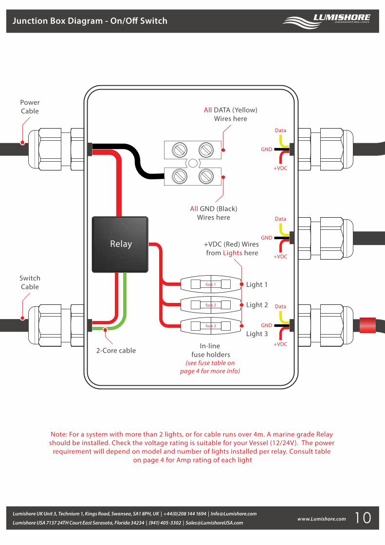
Junction Box Diagram - On/O� Switch
fuse 1
fuse 2
fuse 3
Relay
All GND (Black)Wires here
All DATA (Yellow)Wires here
PowerCable
SwitchCable
In-line fuse holders
(see fuse table on page 4 for more info)
+VDC (Red) Wires from Lights here
Light 1
Light 2
Light 3
2-Core cable
Note: For a system with more than 2 lights, or for cable runs over 4m. A marine grade Relay should be installed. Check the voltage rating is suitable for your Vessel (12/24V). The power
requirement will depend on model and number of lights installed per relay. Consult table on page 4 for Amp rating of each light
Data
+VDC
GND
Data
+VDC
GND
Data
+VDC
GND
10
www.Lumishore.comLumishore UK Unit 3, Technium 1, Kings Road, Swansea, SA1 8PH, UK | +44(0)208 144 1694 | [email protected]
Lumishore USA 7137 24TH Court East Sarasota, Florida 34234 | (941) 405-3302 | [email protected]
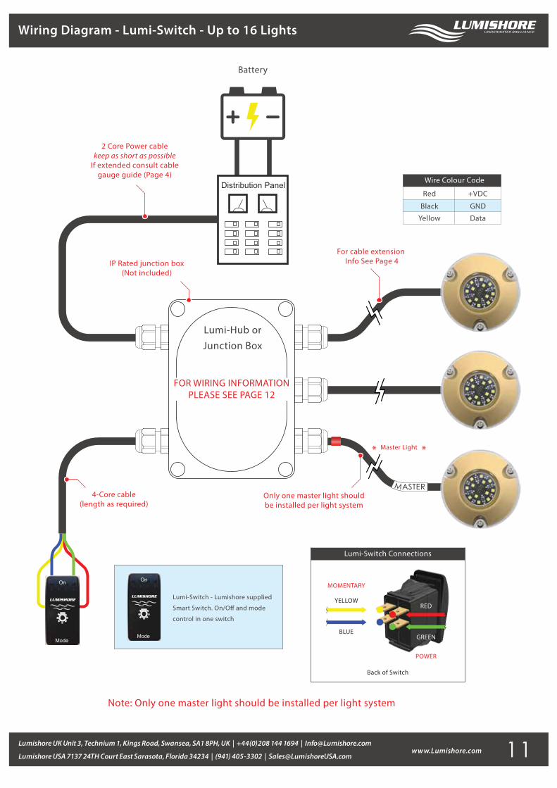
Wiring Diagram - Lumi-Switch - Up to 16 Lights
On
Mode
Lumi-Switch - Lumishore supplied
Smart Switch. On/O� and mode
control in one switch
Lumi-Switch Connections
Back of Switch
YELLOW
BLUE
RED
GREEN
MOMENTARY
POWER
On
Mode
Distribution Panel
Battery
Note: Only one master light should be installed per light system
FOR WIRING INFORMATIONPLEASE SEE PAGE 12
2 Core Power cablekeep as short as possible
If extended consult cablegauge guide (Page 4)
IP Rated junction box(Not included)
4-Core cable(length as required)
Red
Black
+VDC
GND
Yellow Data
Wire Colour Code
Lumi-Hub orJunction Box
For cable extension Info See Page 4
Only one master light should be installed per light system
MASTER
11
www.Lumishore.comLumishore UK Unit 3, Technium 1, Kings Road, Swansea, SA1 8PH, UK | +44(0)208 144 1694 | [email protected]
Lumishore USA 7137 24TH Court East Sarasota, Florida 34234 | (941) 405-3302 | [email protected]
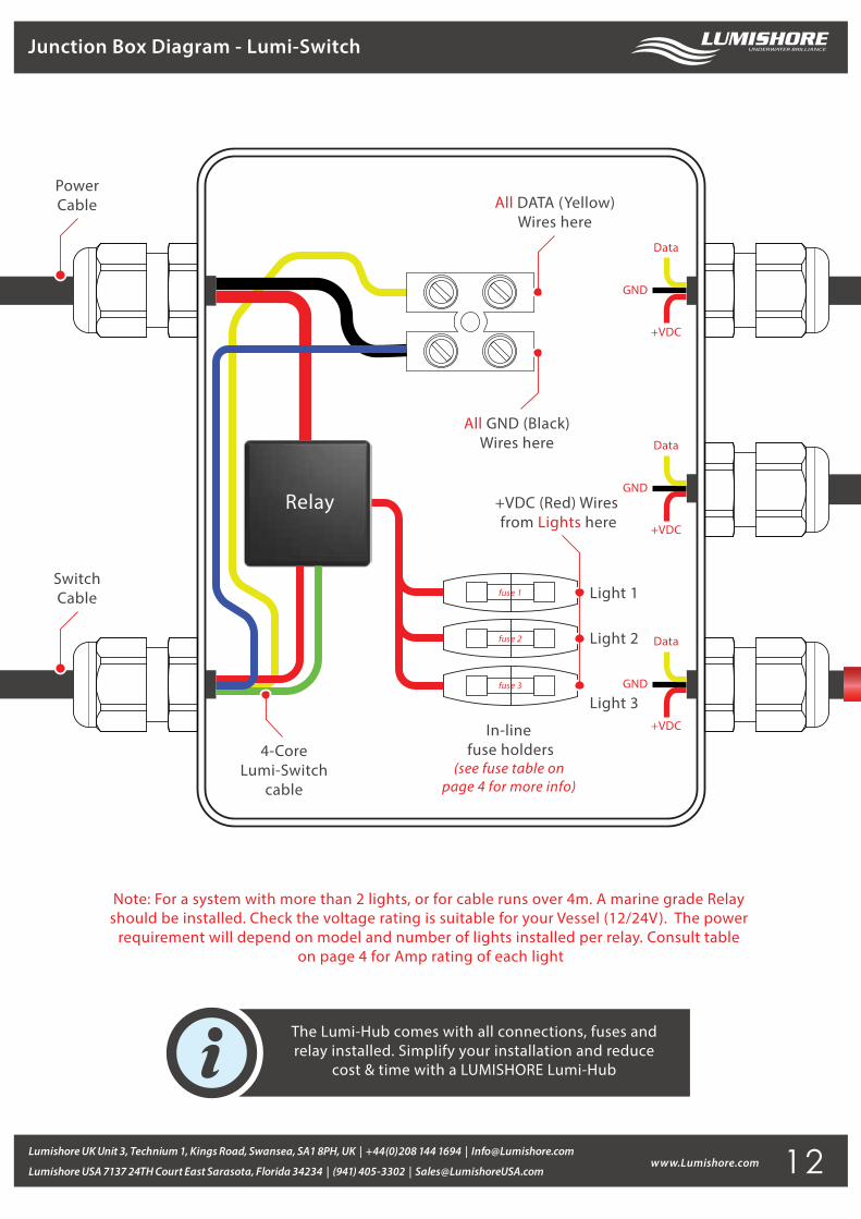
Junction Box Diagram - Lumi-Switch
Note: For a system with more than 2 lights, or for cable runs over 4m. A marine grade Relay should be installed. Check the voltage rating is suitable for your Vessel (12/24V). The power
requirement will depend on model and number of lights installed per relay. Consult table on page 4 for Amp rating of each light
fuse 1
fuse 2
fuse 3
All GND (Black)Wires here
All DATA (Yellow)Wires here
PowerCable
SwitchCable
In-line fuse holders
(see fuse table on page 4 for more info)
+VDC (Red) Wires from Lights here
Light 1
Light 2
Light 3
Relay
4-CoreLumi-Switch
cable
Data
+VDC
GND
Data
+VDC
GND
Data
+VDC
GND
The Lumi-Hub comes with all connections, fuses andrelay installed. Simplify your installation and reduce
cost & time with a LUMISHORE Lumi-Hub
12