Embed Size (px)
Citation preview
Page 1 of 26
SMTMAX Micro Welder Specifications
1.0 SMTMAX Micro Welder Summary
The Micro Welder is a high performance gas-generating soldering unit producing a high temperature flame - in the range of 1200-3300° C - with a reliable, low-cost and safe operation.
1.1 SMTMAX Micro Welder and Strip Welding
The method of direct welding on enameled wire is required to produce and manufacture various electronic parts and components with small coils, because Electric Resistance Weld methods cannot be used due to the insulation on enameled wire; because the existence of the insulation, the Electric Resistance Weld (ERW) cannot proceed.
SMTmax Micro Welder, which is invented and made by SMTmax, is a kind of spot electric welding machine which is professionally applied to producing and manufacturing various electronic parts and components with small coils in the Electronic Industry and Micro-Electronic Industry.
SMTMAX Micro Welder performs STRIPPING AND WELDING, this welding machine has the function of direct welding without stripping the insulation.
For more information about strip welding procedures & theories, please refer to the article “Strip welding—New ERW Technology of Direct Weld Enameled wire. Journal of China Weld”, 2007.
1.2 SMTMAX Spot Electric Welding Machine and Precision Welding
SMTMAX Spot Electric Welding Machine has uniform and stable pulse output, and it can regulate the welding current by adjusting the pulse output. Moreover, SMTMAX Spot Electric Welding Machine also can adjust each pulse output, therefore it can perform precision regulation of the welding current. SMTMAX Micro Welder is currently the finest resistance spot -electric welding machine which can regulate the welding current. It not only can apply direct welding to various small sized enameled wire, but also to provide precision welding for various mini electronic parts and components including the aerospace, medical treatment field, etc.
1.3 SMTMAX Spot Electric Welding Machine Models
SMTMAX Spot Electric Welding Machine has two models. One is a Micro Welder-300A with
Page 2 of 26
300 maximum output current. The other model is a Micro Welder-600 with 600A maximum output current. The Micro Welder-300 applies to weld sizes of enameled wire Ф0.02 mm -φ0.15mm. Micro Welder-600 applies to weld sizes of enameled wires over φ0.15mm.
1.4 SMTMAX Spot Electric Welding Machine Function & Characteristics
1.4.1. A resistance spot electric welding machine can provide precision regulation for welding current;
1.4.2. Single face weld, direct weld enameled wire;
1.4.3. Intelligent output current to guarantee uniform and stable welding;
1.4.4. Electrode has long service life, which can weld more than 20K welds for small size enameled wire;
1.4.5. Can use U-type/Ohm contact type electrode;
1.4.6. Flexible and adjustable pulse output wave shape;
1.4.7. Real time display of welding current and monitor working situation for welding and electrodes;
1.4.8. Independent precious force control header;
1.4.9. Equipped with micro-welding soft-100 computer software, which can record and memorize various welding settings and provide quality data for each unit.
2.0 SMTMAX Spot Electric Welding Machine Circuits Design
2.1 The Basic Theory for SMTMAX’s Spot Electric Welding MachineHow to Achieve Stripping and Welding
SMTMAX Micro Welder adopts capacitance reserve energy. SMTMAX Micro Welder presets three adjustable and controllable welding parameters: weld force, output pulse amplitude (voltage) and output pulse duration (millisecond). While welding, an operator presets the above-mentioned three parameters according to the different wire sizes and demands of the weldments. When the weld force, which applies on the Electrode, reaches the set point, the micro switch is triggered and the current is turned on. The tip of the Electrode generates electric sparks after switching on, for there is an Ohmic contact or connector with a preset certain value on the tip of the parallel electrodes. One part of the insulation which contacts the
Page 3 of 26
SMTMAX electrode
E l d i
Metal base
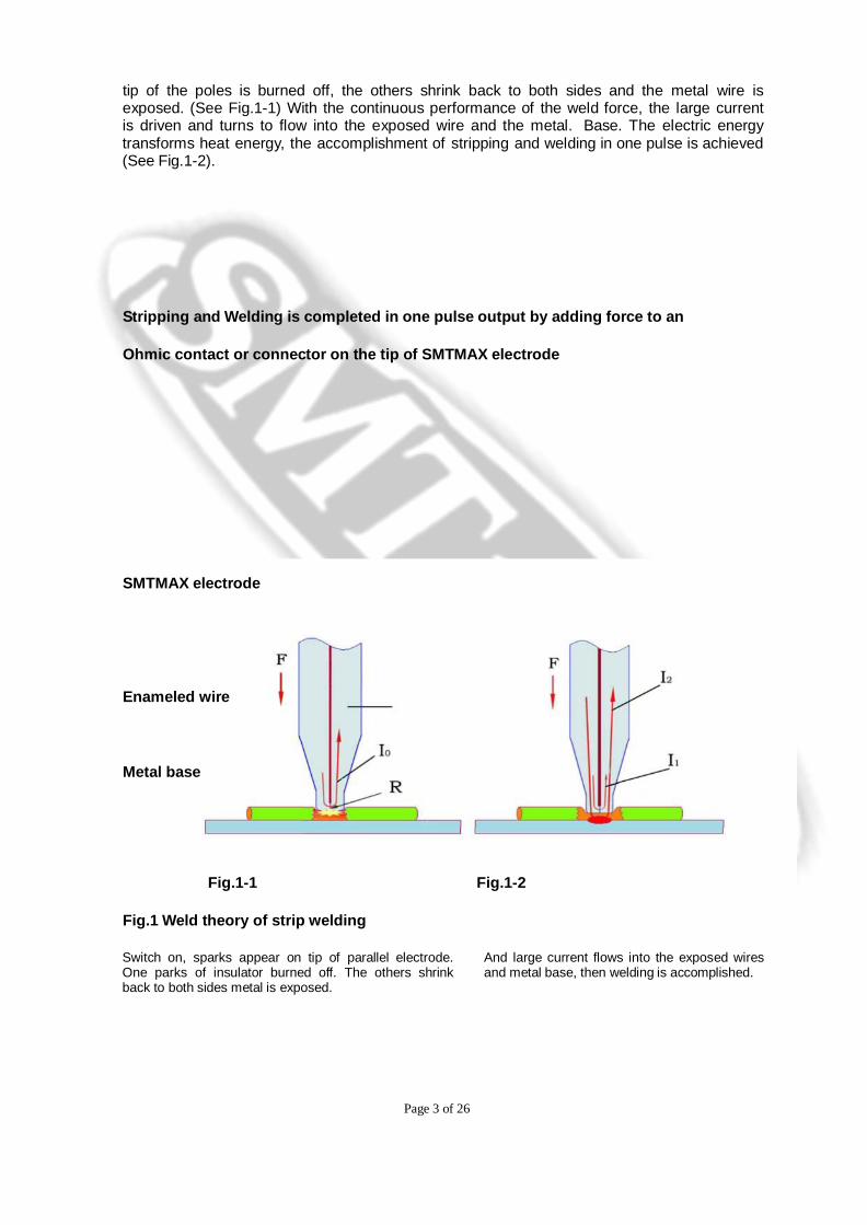
tip of the poles is burned off, the others shrink back to both sides and the metal wire is exposed. (See Fig.1-1) With the continuous performance of the weld force, the large current is driven and turns to flow into the exposed wire and the metal. Base. The electric energy transforms heat energy, the accomplishment of stripping and welding in one pulse is achieved (See Fig.1-2).
Stripping and Welding is completed in one pulse output by adding force to an
Ohmic contact or connector on the tip of SMTMAX electrode
SMTMAX electrode
Enameled wire
Metal base
Fig.1-1 Fig.1-2
Fig.1 Weld theory of strip welding
Switch on, sparks appear on tip of parallel electrode. One parks of insulator burned off. The others shrink back to both sides metal is exposed.
And large current flows into the exposed wires and metal base, then welding is accomplished.
Page 4 of 26
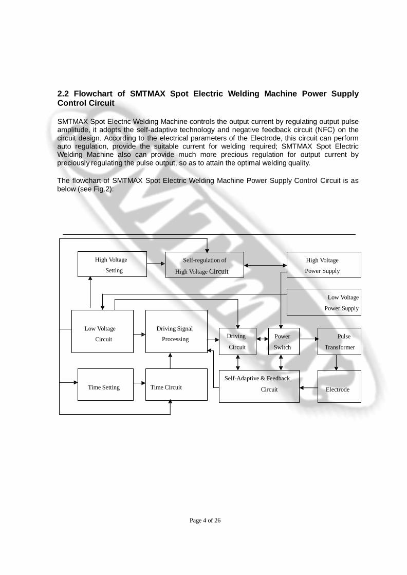
2.2 Flowchart of SMTMAX Spot Electric Welding Machine Power Supply Control Circuit
SMTMAX Spot Electric Welding Machine controls the output current by regulating output pulse amplitude, it adopts the self-adaptive technology and negative feedback circuit (NFC) on the circuit design. According to the electrical parameters of the Electrode, this circuit can perform auto regulation, provide the suitable current for welding required; SMTMAX Spot Electric Welding Machine also can provide much more precious regulation for output current by preciously regulating the pulse output, so as to attain the optimal welding quality.
The flowchart of SMTMAX Spot Electric Welding Machine Power Supply Control Circuit is as below (see Fig.2):
High Voltage
Setting Self-regulation of
High Voltage Circuit High Voltage
Power Supply
Low Voltage
Power Supply
Low Voltage
Circuit
Driving Signal
Processing Driving Circuit
Power
Switch
Pulse
Transformer
Time Setting Time Circuit Self-Adaptive & Feedback
Circuit
Electrode
Page 5 of 26
Fig.2 Flowchart of SMTMAX Spot Electric Welding Machine Power Supply Control Circuit
2.3 SMTMAX Spot Electric Welding Machine Welding Current
Compensation Theory
SMTMAX Spot Electric Welding Machine is a fine resistance welding machine, which uses heavy current to pass through the metal area connecting with the electrode in a split second and the metal area generates resistance heat to accomplish welding. The heat for welding required is Joule's law Q=0.24I2Rt.
All traditional resistance welding machines only focus unilaterally on constant output current, but neglect resistance value change. The parts and components to be welded by SMTMAX Spot Electric Welding Machine are very small, it is always requested to weld enameled wire with φ0.03~0.05mm, in addition to its special structure, the resistance value change is fully considered during welding on the power supply control circuit design of SMTMAX Spot Electric Welding Machine to guarantee the constant output energy and innovatively raises “current compensation” theory by discarding the traditional consideration for constant current only. The “current compensation” theory is: during welding, if resistance value is small, then increase output current; if resistance value becomes larger, then reduce output current. It can intelligently control output current to guarantee the constant welding energy and achieve uniform, reliable and stable welding.
SMTMAX Spot Electric Welding Machine applies a high precision current sensor and analog current technology, which can accurately inspect and show real time current value for each weld. Due to its current compensation circuit, the larger current value will be seen in the beginning of welding, it can achieve constant current and even pace welding with thermal balance. The current value at that time can be used to be a standard to judge electrode quality and reliability of weld.
2.4 Output Pulse Amplitude Settings on SMTMAX Spot Electric Welding Machine
2.4.1 Stripping Pulse and Pulse Climb Angle
As per strip welding theory and process: the front portion of pulse is for stripping, the back portion is for welding. Research shows, stripping pulse amplitude is a little smaller than welding pulse amplitude, but with similar duration (Refer to the article “Strip welding—New ERW Technology of Direct Weld Enameled wire” issued on “Journal of China Weld”, 2007).
Page 6 of 26
In order to improve welding quality and lengthen electrode service life, based on output pulse amplitude and duration settings, SMTMAX Spot Electric Welding Machine innovatively provides the setting for the front portion of pulse output amplitude, which not only meets stripping requirement, but also can be treated as pre-pulse setting, if you need to weld mini size metal wires and metal tapes. This pre-pulse setting is good to reduce splashing in the early phase and flux forming on joined surfaces.
Capacitance reserve energy model welding machines can discharge in a very short time and the peak value is very high, SMTMAX Spot Electric Welding Machine design has a special control for Pulse Amplitude Climb Angle to restrain shock on parts/components and electrodes by the heavy moment current.
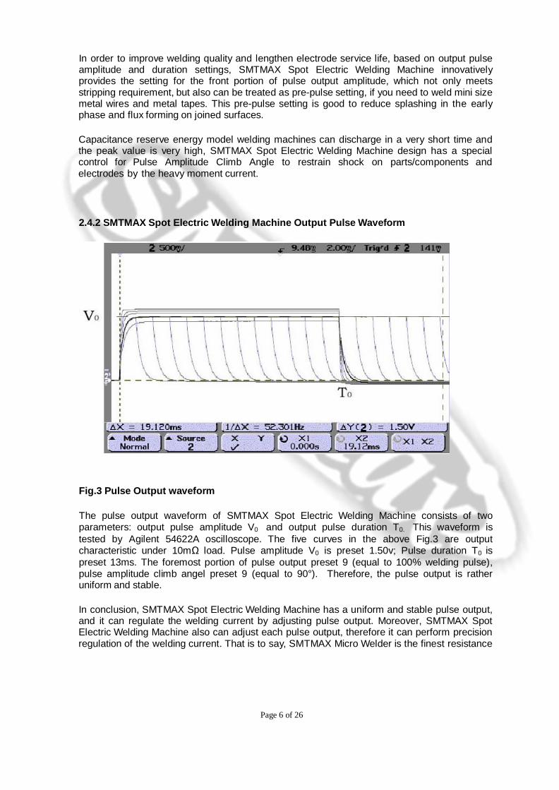
2.4.2 SMTMAX Spot Electric Welding Machine Output Pulse Waveform
Fig.3 Pulse Output waveform
The pulse output waveform of SMTMAX Spot Electric Welding Machine consists of two parameters: output pulse amplitude V0 and output pulse duration T0. This waveform is tested by Agilent 54622A oscilloscope. The five curves in the above Fig.3 are output characteristic under 10mΩ load. Pulse amplitude V0 is preset 1.50v; Pulse duration T0 is preset 13ms. The foremost portion of pulse output preset 9 (equal to 100% welding pulse), pulse amplitude climb angel preset 9 (equal to 90°). Therefore, the pulse output is rather uniform and stable.
In conclusion, SMTMAX Spot Electric Welding Machine has a uniform and stable pulse output, and it can regulate the welding current by adjusting pulse output. Moreover, SMTMAX Spot Electric Welding Machine also can adjust each pulse output, therefore it can perform precision regulation of the welding current. That is to say, SMTMAX Micro Welder is the finest resistance
Page 7 of 26
spot electronic welding machine which can regulate the finest welding current. It not only can apply to direct weld various small size of the enameled wires, but also to provide precision weld for various mini electronic parts and components including the aerospace, medical treatment field etc.
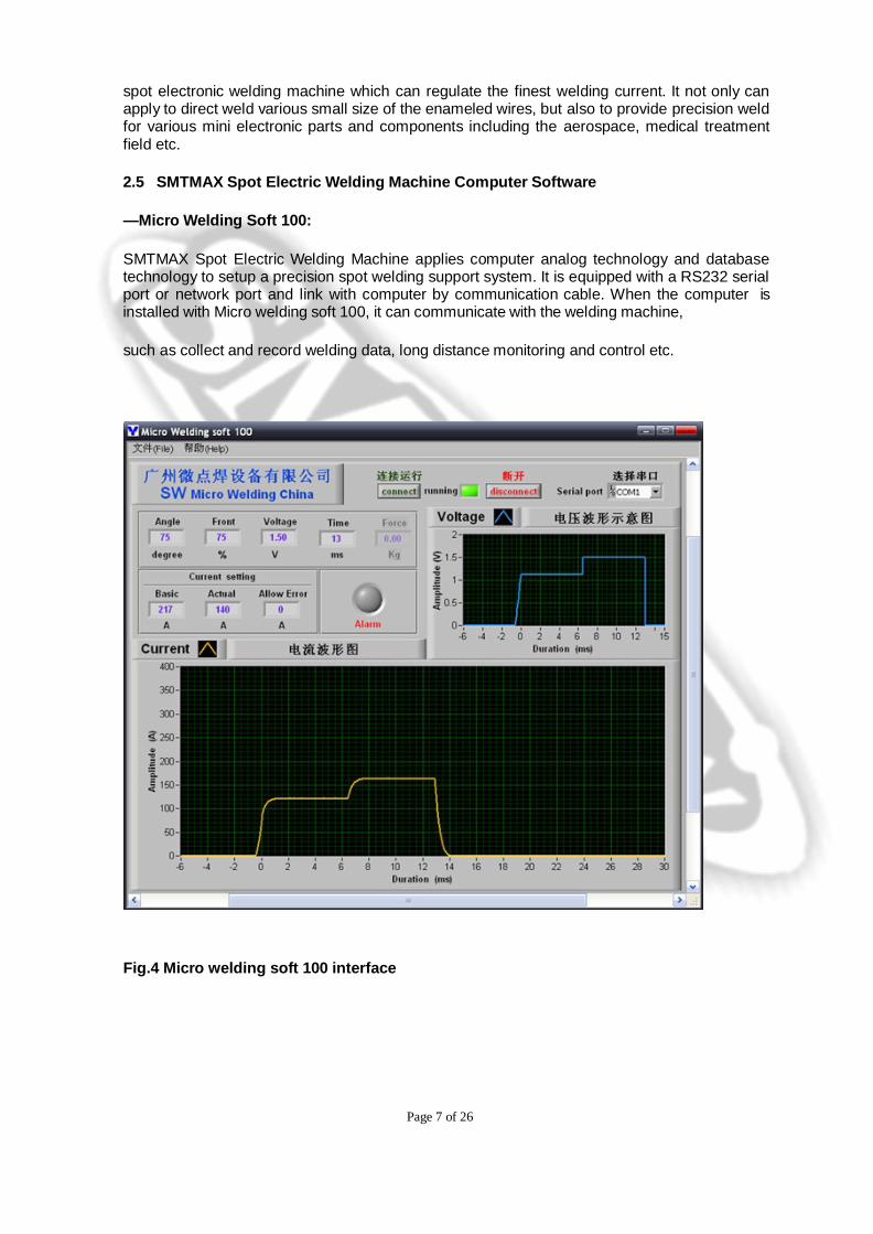
2.5 SMTMAX Spot Electric Welding Machine Computer Software
—Micro Welding Soft 100:
SMTMAX Spot Electric Welding Machine applies computer analog technology and database technology to setup a precision spot welding support system. It is equipped with a RS232 serial port or network port and link with computer by communication cable. When the computer is installed with Micro welding soft 100, it can communicate with the welding machine,
such as collect and record welding data, long distance monitoring and control etc.
Fig.4 Micro welding soft 100 interface
Page 8 of 26
Welding data includes weld force, output pulse amplitude (voltage) and output pulse duration (millisecond). Applied with Micro welding soft 100, all the welding data for each unit during production can be recorded in the computer database to ensure traceability. It can provide good assistance for the aerospace and medical treatment industry etc, which require you to show the “Birth Certificate” (original record).
SMTMAX Spot Electric Welding Machine offers long distance control through the computer monitor aswell. Under the long distance monitor function of Micro welding soft 100, it can show all used weld parameters for each weld spot in the computer by graph and text. Moreover, through this long distance control function, it even can debug and modify weld parameters so as to achieve long distance control welding.
Fig.4 is the pulse output interface recorded through the computer by using the SMTMAX Spot Electric Welding Machine Micro welding soft 100. Except pulse current is the actual tested value, pulse climb angel, stripping pulse, pulse amplitude and duration is the preset value.
In the pulse output waveform of above Fig.4, pulse climb angel is 75°(preset 6), pulse amplitude V0 is 1.50v, stripping pulse is 75%×1.50V(preset 4), pulse duration T0 is 13ms. From the view of total output pulse, pulse output shows 75°slope climbing, the front half portion and the back half portion of pulse form a continuous dual pulse – ladder wave, the front half portion is pre-heat or stripping pulse, the back half portion is welding pulse. From the pulse current records, the output current of 1st spot and 2nd spot in the beginning of welding are largest, then they becomes smaller and more stable, because the resistance is smallest in the beginning of welding, resistance and output current will become stable when heat balance is achieved.
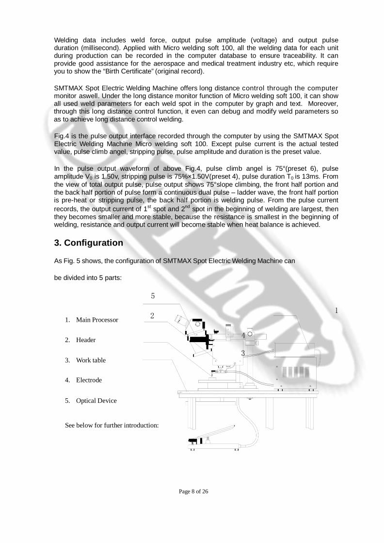
3. Configuration
As Fig. 5 shows, the configuration of SMTMAX Spot Electric Welding Machine can
be divided into 5 parts:
5
1
1. Main Processor 2
4 2. Header
3 3. Work table
4. Electrode
5. Optical Device
See below for further introduction:

Page 9 of 26
See below for further introduction:
Fig.5 SMTMAX Spot Electric Welding Machine Configuration
3.1 Main Processor
Main Processor provides a controllable welding power supply for SMTMAX Spot Electric Welding Machine, its main internal configuration contains a Power Transformer, Output Pulse Transformer, Bulk Capacitor and Control Circuit to regulate output power, which configuration is introduced in previous section 2.0.
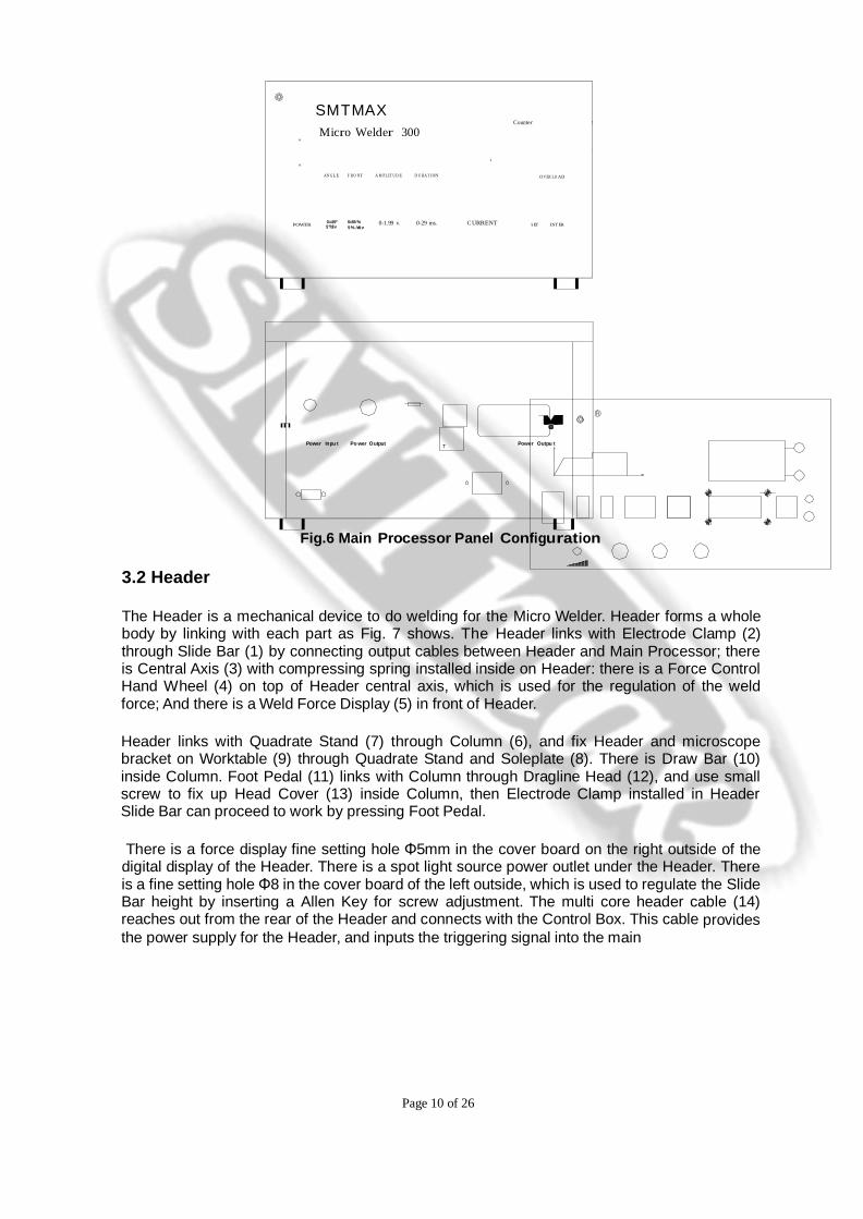
In the front panel of the Transformer Box has four driving plate switches (Output Pulse Amplitude, Output Pulse Duration, Output Pulse Climb Angle and Front Portion Output Pulse Amplitude, that is the Stripping Pulse), a Counter Display Screen with Counter Reset Switch and Counter Store switch in the right side, a Current Display Screen with Enter Switch and Set Switch for current tolerance in the right side, a Power Master switch, an Overload Display Signal, Mini-Lamp outlet and Dimmer, two Output Cables link with the electrode clamp and Power Outlet link with Header.
In the rear panel of the Transformer Box as an Input Power Outlet, a Fuse Holder, two Output Power Outlets, an Output Pulse Amplitude Mini-Regulation Port for calibration uniform output for additional welding machines, a RS232 Serial Port connecting to the
computer so memory can record various welding parameters.
Page 10 of 26
SMT MAX
Counter T
Micro Welder 300 V
E
T 0
AN G LE F RO N T A M PL IT U D E D U RA T IO N O V ER LO AD
POWER 0=45° 0=55 % 0-1.99 v. 0-29 ms. C URRENT S ET EN T ER
5°/div 5 % /div
Power In pu t Po wer Output T Power Outpu t
Fig.6 Main Processor Panel Configuration
3.2 Header
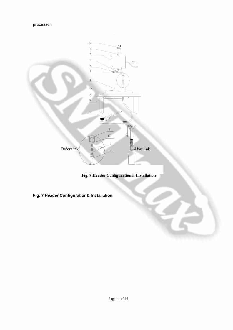
The Header is a mechanical device to do welding for the Micro Welder. Header forms a whole body by linking with each part as Fig. 7 shows. The Header links with Electrode Clamp (2) through Slide Bar (1) by connecting output cables between Header and Main Processor; there is Central Axis (3) with compressing spring installed inside on Header: there is a Force Control Hand Wheel (4) on top of Header central axis, which is used for the regulation of the weld force; And there is a Weld Force Display (5) in front of Header.
Header links with Quadrate Stand (7) through Column (6), and fix Header and microscope bracket on Worktable (9) through Quadrate Stand and Soleplate (8). There is Draw Bar (10) inside Column. Foot Pedal (11) links with Column through Dragline Head (12), and use small screw to fix up Head Cover (13) inside Column, then Electrode Clamp installed in Header Slide Bar can proceed to work by pressing Foot Pedal.
There is a force display fine setting hole Φ5mm in the cover board on the right outside of the digital display of the Header. There is a spot light source power outlet under the Header. There is a fine setting hole Φ8 in the cover board of the left outside, which is used to regulate the Slide Bar height by inserting a Allen Key for screw adjustment. The multi core header cable (14) reaches out from the rear of the Header and connects with the Control Box. This cable provides the power supply for the Header, and inputs the triggering signal into the main
Page 11 of 26
processor.
4
F 3
5
1 14
2
6
7
15
8
9
11
6
10
Before ink
12
13 After link
Fig. 7 Header Configuration& Installation
Fig. 7 Header Configuration& Installation
Page 12 of 26
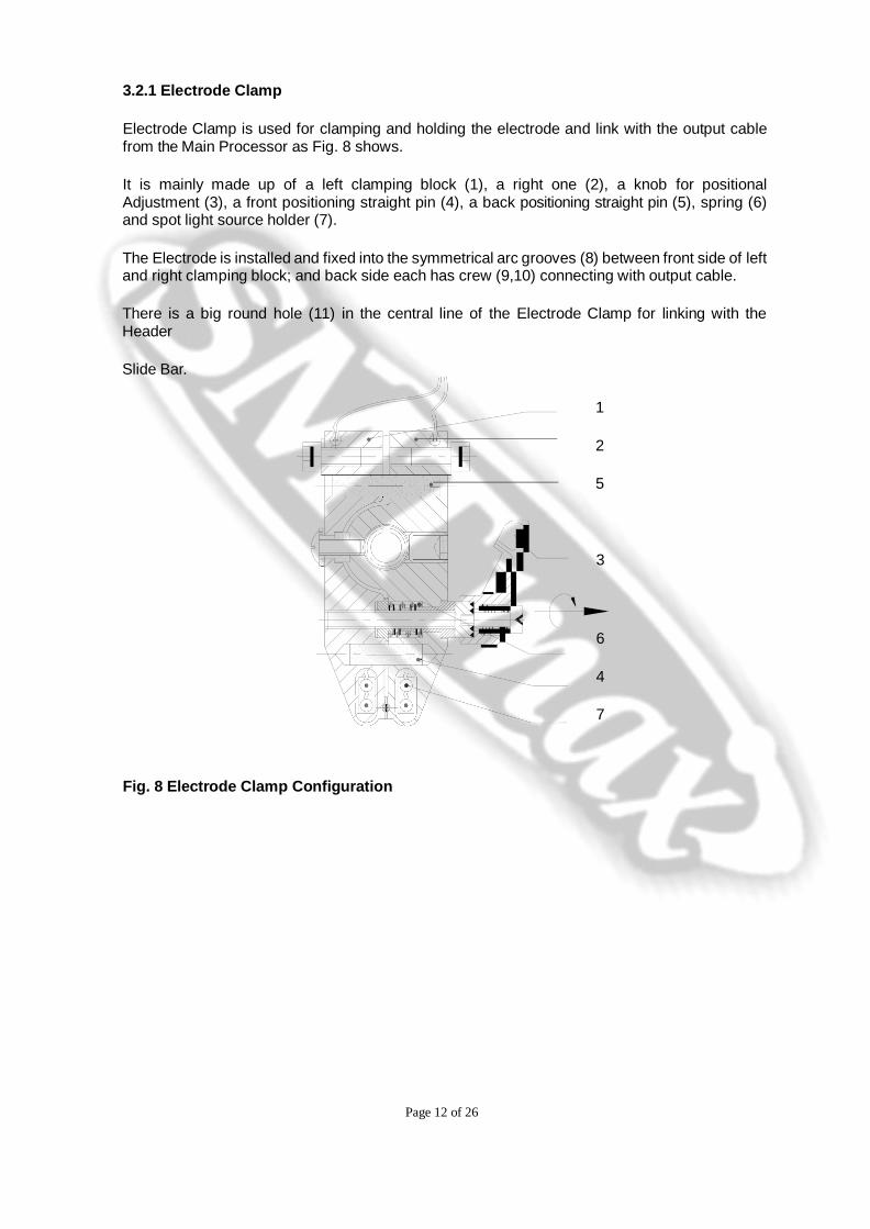
3.2.1 Electrode Clamp
Electrode Clamp is used for clamping and holding the electrode and link with the output cable from the Main Processor as Fig. 8 shows.
It is mainly made up of a left clamping block (1), a right one (2), a knob for positional Adjustment (3), a front positioning straight pin (4), a back positioning straight pin (5), spring (6) and spot light source holder (7).
The Electrode is installed and fixed into the symmetrical arc grooves (8) between front side of left and right clamping block; and back side each has crew (9,10) connecting with output cable.
There is a big round hole (11) in the central line of the Electrode Clamp for linking with the Header
Slide Bar.
1
2
5
3
6
4
7
Fig. 8 Electrode Clamp Configuration
Page 13 of 26
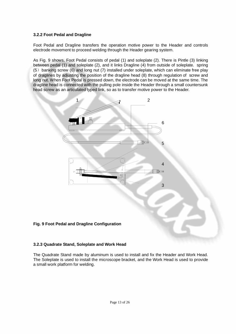
3.2.2 Foot Pedal and Dragline
Foot Pedal and Dragline transfers the operation motive power to the Header and controls electrode movement to proceed welding through the Header gearing system.
As Fig. 9 shows, Foot Pedal consists of pedal (1) and soleplate (2). There is Pintle (3) linking between pedal (1) and soleplate (2), and it links Dragline (4) from outside of soleplate. spring (5) banking screw (6) and long nut (7) installed under soleplate, which can eliminate free play of draglines by adjusting the position of the dragline head (8) through regulation of screw and long nut. When Foot Pedal is pressed down, the electrode can be moved at the same time. The dragline head is connected with the pulling pole inside the Header through a small countersunk head screw as an articulated typed link, so as to transfer motive power to the Header.
1 2
6
5
4
3
Fig. 9 Foot Pedal and Dragline Configuration
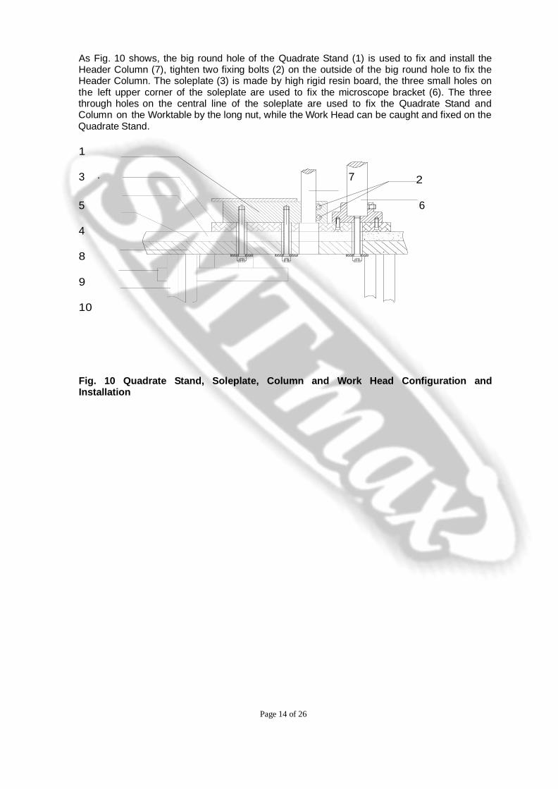
3.2.3 Quadrate Stand, Soleplate and Work Head
The Quadrate Stand made by aluminum is used to install and fix the Header and Work Head. The Soleplate is used to install the microscope bracket, and the Work Head is used to provide a small work platform for welding.
Page 14 of 26
.
As Fig. 10 shows, the big round hole of the Quadrate Stand (1) is used to fix and install the Header Column (7), tighten two fixing bolts (2) on the outside of the big round hole to fix the Header Column. The soleplate (3) is made by high rigid resin board, the three small holes on the left upper corner of the soleplate are used to fix the microscope bracket (6). The three through holes on the central line of the soleplate are used to fix the Quadrate Stand and Column on the Worktable by the long nut, while the Work Head can be caught and fixed on the Quadrate Stand.
1
3 7 2
5 6
4
8
9
10
Fig. 10 Quadrate Stand, Soleplate, Column and Work Head Configuration and Installation
Page 15 of 26
3.3 Worktable
SMTMAX Spot Electric Welding Machine does welding by placing the Header on the Worktable. The Worktable is also used to place the Main Processor and fixed optical device.
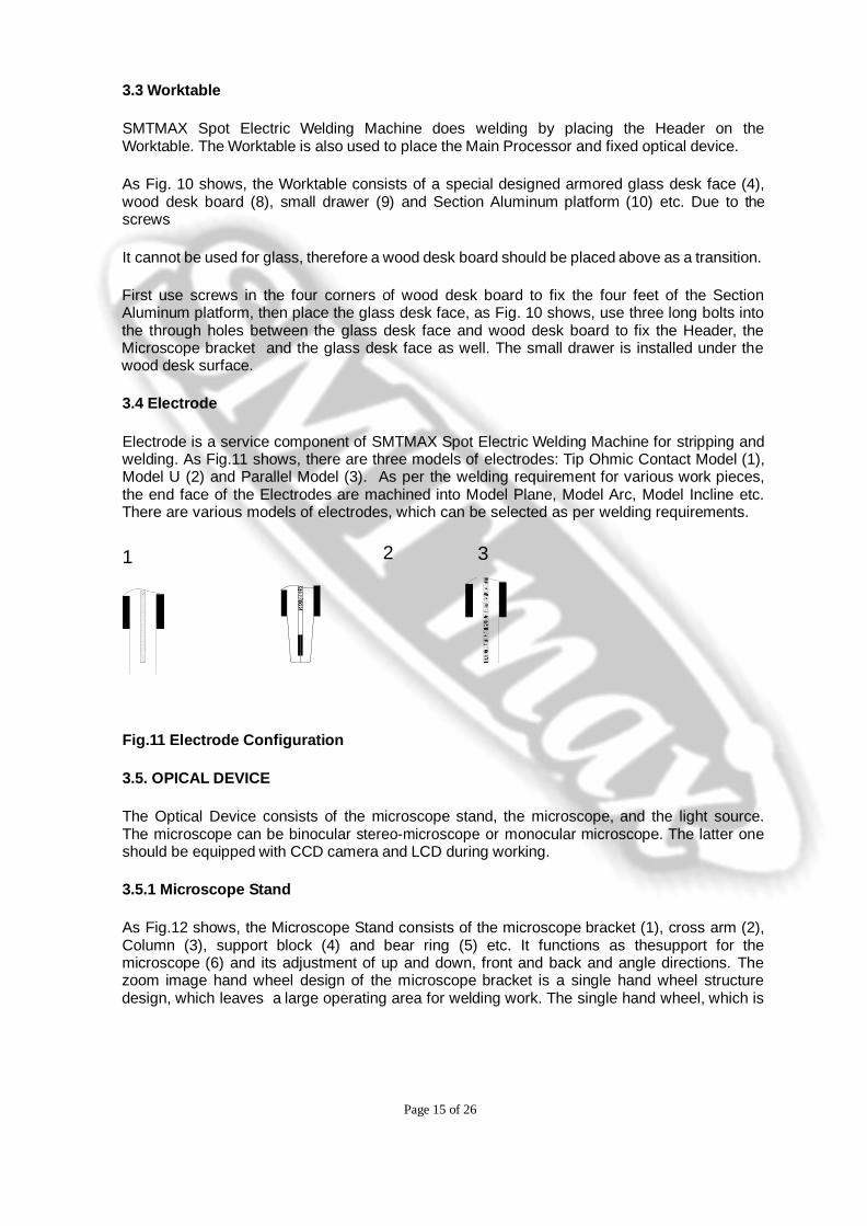
As Fig. 10 shows, the Worktable consists of a special designed armored glass desk face (4), wood desk board (8), small drawer (9) and Section Aluminum platform (10) etc. Due to the screws
It cannot be used for glass, therefore a wood desk board should be placed above as a transition.
First use screws in the four corners of wood desk board to fix the four feet of the Section Aluminum platform, then place the glass desk face, as Fig. 10 shows, use three long bolts into the through holes between the glass desk face and wood desk board to fix the Header, the Microscope bracket and the glass desk face as well. The small drawer is installed under the wood desk surface.
3.4 Electrode
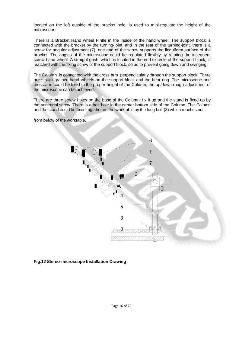
Electrode is a service component of SMTMAX Spot Electric Welding Machine for stripping and welding. As Fig.11 shows, there are three models of electrodes: Tip Ohmic Contact Model (1), Model U (2) and Parallel Model (3). As per the welding requirement for various work pieces, the end face of the Electrodes are machined into Model Plane, Model Arc, Model Incline etc. There are various models of electrodes, which can be selected as per welding requirements.
1 2 3
Fig.11 Electrode Configuration
3.5. OPICAL DEVICE
The Optical Device consists of the microscope stand, the microscope, and the light source. The microscope can be binocular stereo-microscope or monocular microscope. The latter one should be equipped with CCD camera and LCD during working.
3.5.1 Microscope Stand
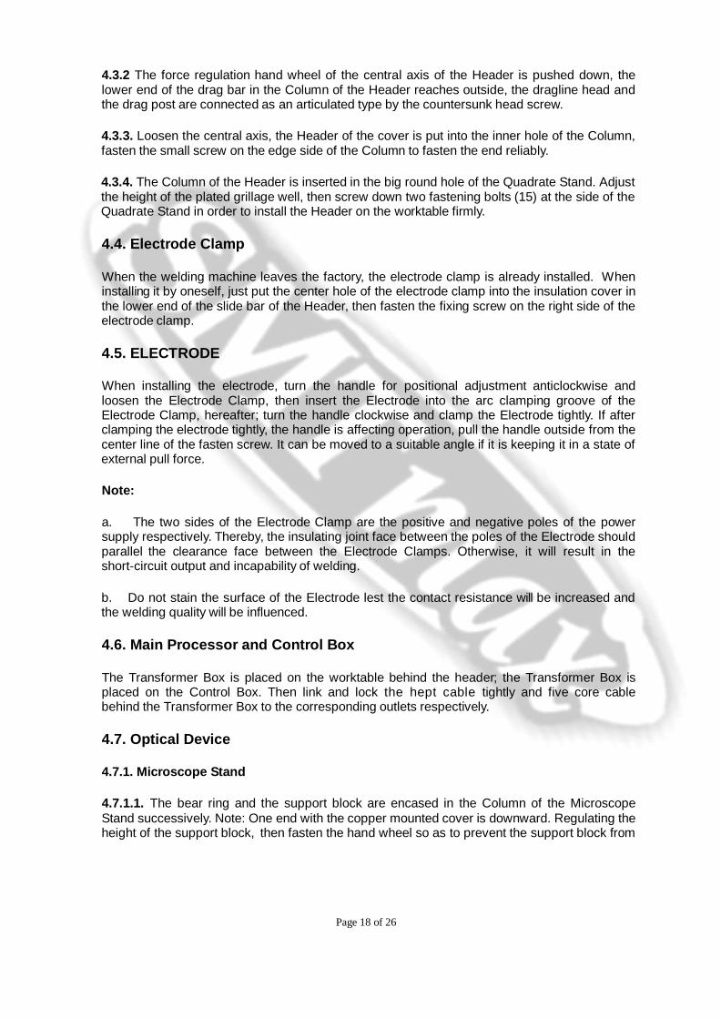
As Fig.12 shows, the Microscope Stand consists of the microscope bracket (1), cross arm (2), Column (3), support block (4) and bear ring (5) etc. It functions as thesupport for the microscope (6) and its adjustment of up and down, front and back and angle directions. The zoom image hand wheel design of the microscope bracket is a single hand wheel structure design, which leaves a large operating area for welding work. The single hand wheel, which is
Page 16 of 26
located on the left outside of the bracket hole, is used to mini-regulate the height of the microscope.
There is a Bracket Hand wheel Pintle in the inside of the hand wheel. The support block is connected with the bracket by the turning-joint, and in the rear of the turning-joint, there is a screw for angular adjustment (7), one end of the screw supports the linguiform surface of the bracket. The angles of the microscope could be regulated flexibly by rotating the insequent screw hand wheel. A straight gash, which is located in the end exicrcle of the support block, is matched with the fixing screw of the support block, so as to prevent going down and swinging.
The Column is connected with the cross arm perpendicularly through the support block. There are straigt grained hand wheels on the support block and the bear ring. The microscope and cross arm could be fixed to the proper height of the Column; the up/down rough adjustment of the microscope can be achieved.
There are three screw holes on the base of the Column; fix it up and the stand is fixed up by the sectrorial screw. There is a bolt hole in the center bottom side of the Column. The Column and the stand could be fixed together on the worktable by the long bolt (8) which reaches out
from below of the worktable.
6
1
7
2
4
5
3
8
Fig.12 Stereo-microscope Installation Drawing

Page 17 of 26
3.5.2 Microscope
3.5.2.1. Stereo-microscope
The stereo-microscope, which is used on the SMTMAX Spot Electric Welding Machine, is convenient to perform welding under the straight watch of the microscope. On the stereo-microscope, there is a pair of 10x eyepieces and 0.5x or 0.75x large objective.
3.5.2.2. Monocular microscope
The monocular microscope is another device of the optical device, which is equipped with the CCD
camera and LCD. The operator can operate by watching the LCD.
3.5.3. Light Source
The illuminance of the stereo-microscope and the welding is provided by the specially designed ring-shaped Mini-Lamp and four white LBD on the Electrode Clamp separately. It has a soft and natural light, evident effect of mitigating visual fatigue and improvement in work efficiency.
4. Installation
After installation, SMTMAX Spot Electric Welding Machine should be as Fig.5 shows, the simple installation steps are as follows:
4.1 Worktable
Install the Section Aluminum platform by using four screws to fix the four corners of the wood desk board and platform feet. Then install the small drawer underneath of the wood desk board.
4.2 Fix and installation for the soleplate, the Column, the Quadrate Stand and worktable
See Fig. 10, first use a countersunk head screw to fix the soleplate and the column of the microscope, then insert and tighten three long bolts by through holes among wood desk board, the soleplate and the armored glass desk face and fix the quadrate stand and the column base respectively.
4.3 Header
4.3.1 See Fig. 7, the dragline head of the pedal reaches out from bottom to top from the round hole of the Quadrate Stand.
Page 18 of 26
4.3.2 The force regulation hand wheel of the central axis of the Header is pushed down, the lower end of the drag bar in the Column of the Header reaches outside, the dragline head and the drag post are connected as an articulated type by the countersunk head screw.
4.3.3. Loosen the central axis, the Header of the cover is put into the inner hole of the Column, fasten the small screw on the edge side of the Column to fasten the end reliably.
4.3.4. The Column of the Header is inserted in the big round hole of the Quadrate Stand. Adjust the height of the plated grillage well, then screw down two fastening bolts (15) at the side of the Quadrate Stand in order to install the Header on the worktable firmly.
4.4. Electrode Clamp
When the welding machine leaves the factory, the electrode clamp is already installed. When installing it by oneself, just put the center hole of the electrode clamp into the insulation cover in the lower end of the slide bar of the Header, then fasten the fixing screw on the right side of the electrode clamp.
4.5. ELECTRODE
When installing the electrode, turn the handle for positional adjustment anticlockwise and loosen the Electrode Clamp, then insert the Electrode into the arc clamping groove of the Electrode Clamp, hereafter; turn the handle clockwise and clamp the Electrode tightly. If after clamping the electrode tightly, the handle is affecting operation, pull the handle outside from the center line of the fasten screw. It can be moved to a suitable angle if it is keeping it in a state of external pull force.
Note:
a. The two sides of the Electrode Clamp are the positive and negative poles of the power supply respectively. Thereby, the insulating joint face between the poles of the Electrode should parallel the clearance face between the Electrode Clamps. Otherwise, it will result in the short-circuit output and incapability of welding.
b. Do not stain the surface of the Electrode lest the contact resistance will be increased and the welding quality will be influenced.
4.6. Main Processor and Control Box
The Transformer Box is placed on the worktable behind the header; the Transformer Box is placed on the Control Box. Then link and lock the hept cable tightly and five core cable behind the Transformer Box to the corresponding outlets respectively.
4.7. Optical Device
4.7.1. Microscope Stand
4.7.1.1. The bear ring and the support block are encased in the Column of the Microscope Stand successively. Note: One end with the copper mounted cover is downward. Regulating the height of the support block, then fasten the hand wheel so as to prevent the support block from

Page 19 of 26
sliding down under the gravity of the microscope.
4.7.1.2. Drill the cross arm through another hole of the support block. Note: the direction of the straight gash is downward. Adjust the length of the cross arm then fasten the hand wheel and the fixing screw of the support block so as to prevent falling because of the circumrotation of the microscope.
4.7.2. Stereo-Microscope
First install the zoom objective, then the eyepieces and fasten the fixing screw tightly on the microscope bracket.
4.7.3 Monocular Microscope, CCD and LCD
After linking the monocular microscope and CCD, put them into the monocular microscope bracket and fasten tightly the fixing screw on the bracket. After linking with the CCD and LCD camera, then link the power supply of CCD and LCD respectively.
4.7.4. Light Source
The stereo-microscope can use the Mini-Lamp. Cover the big objective or the connecting piece by the interface of Mini-Lamp, then fasten the three knurled screws and use the power supply from the back side of the transformer box.
Both stereo-microscope and monocular microscopes can link the white LBD Mini-Lamp by fastening the female screw directly into the male screw on the microscope lens. There is a corresponding outlet for power supply on the transformer box front panel, and it can adjust the luminosity of the Mini-Lamp as per requirements.
4.8. COMPLETE MACHINE
4.8.1. Tightly connect two output cables in the face of the Transformer Box with the fix screw of the two sides of the Electrode respectively. Insert the five core cable and hept cable in the rear of the Transformer Box into the corresponding outlets in the rear of the Control Box respectively.
4.8.2. Connect the Header cable of the Header with the outlet on the front panel of the Control
Box.
4.8.3. Regulate the height of the microscope and the magnification times so as to brighten the field of vision.
4.8.4. Insert the power plug, turn on the power master switch, then the Micro Welder can work.

Page 20 of 26
5. OPERATION
5.1. SETTING & ADJUSTMENT OF THREE WELDING PARAMETERS
The setting and adjustment of three welding parameters: weld force, output pulse amplitude (voltage) and output pulse duration (millisecond) are three essential factors for quality welding. Various welded work pieces, including various size and type of enameled wire and various construction of work piece substrate, different electrode model has different requirements. Therefore, the operator must set the three welding parameters properly. The setting parameters in Table 9 are only for reference.
5.1.1 Weld force
Electric resistance welding is called force welding as well. Force should be applied during welding so as to guarantee the electric current enters. The magnitude of applied force is related to enameled wire size, matrix hardness, electrode model and size. Refer to Table 9 for force applied when weld different size of enameled wire. As per Table 9, the thicker the enameled wire size for the welded work piece, a stronger weld force is required.
5.1.2 Output pulse amplitude (V) and output pulse duration (T)
According to Joule’s law, welding energy E=0.24I2RT. Refer to Table 9, the thicker the enameled wire size for the welded work piece, the more welding energy is required. Electric current and voltage are in direct proportion, the setting voltage will be higher accordingly, so is the longer weld time.
The setting and adjustment of output pulse amplitude (V) and output pulse duration (T) is still related to electrode configuration. Generally speaking, the bigger configuration of two tips for electrode poles, the higher welding pulse parameters.
The welding parameters in Table 9 are listed as per the usage of the Ohmic contact model electrode. Because of the configuration of the Model U electrode, a certain amount of electric current density should be applied to electrode tip to proceed welding. Moreover, each work piece has different requirements for electrode configuration. Therefore, the setting and adjustment of the output pulse for Model U electrode should be determined according to the actual situation for electrode and work piece. When setting and adjusting the three welding parameters: weld force, output pulse amplitude (V) and output pulse duration (T), the change of output pulse amplitude (V) is most sensitive, therefore, when setting and adjusting for output pulse amplitude (V), the parameter cannot be changed too much, not more than 0.05V for each setting and adjustment is recommended.

Page 21 of 26
5.2 The choice for pulse output wave shape
SMTMAX Spot Electric Welding Machine is equipped with two main adjustment parameters: output pulse amplitude and output pulse duration so as to guarantee the necessary energy for welding.
For Micro Welder 300, the output pulse amplitude is 0~1.99V, the output pulse duration is 0~
29ms. For Micro Welder 600, the output pulse amplitude is 0~2.99V, the output pulse duration is 0~49ms. Furthermore, SMTMAX Spot Electric Welding Machine is still equipped with the front portion of pulse output amplitude (that is stripping pulse) and pulse amplitude climb angle to meet various enameled wires and work pieces.
There is a dial switch to adjust the stripping pulse amplitude on the front panel of the welding machine, when set to “0”, the stripping pulse amplitude is 55% of the welding pulse. Dial one division forward means adding 5%, and when dial to “9”, the pulse output is a square wave. There is a dial switch to adjust the pulse amplitude climb angle on the front panel of the welding machine, when set to “0”, the angle is 45°. Dial one division forward means adding 5°, and when dial to “9”, the angle is
90°. The below table is the corresponding values shown on the setting output pulse wave shape, when adjusting the dial switch for the front portion of pulse amplitude (stripping) and the pulse climb angle.
Corresponding value for Stripping and Angle dial number:
Dial no. Output pulse
0
1
2
3
4
5
6
7
8
9 Stripping(%)
55
60
65
70
75
80
85
90
95
100
A l
45°
50°
55°
60°
65°
70°
75°
80°
85°
90° The setting and adjustment for pulse output amplitude climb angle not only can restrain the peak value for output electric current, but also can be treated as the pre-pulse setting. For example, for enameled wire at φ0.10mm, the welding angle is generally set at about 75°. If enameled wire is
bigger, the angle can increase 5°~10°. If enameled wire is smaller, then the angle can reduce accordingly.
The setting and adjustment for the front portion of the pulse output amplitude not only can reduce the output electric current in the stripping phase, but can also lengthen the electrode service life. For example, for enameled wire at φ0.10mm, the adjustment amplitude can be controlled at about 75% of output pulse amplitude. If enameled wire is bigger, the amplitude can increase 5%~10%. If enameled wire is smaller, then the amplitude can reduce accordingly. But

Page 22 of 26
if the stripping pulse amplitude is too low, it can cause unreliable welding. Therefore, the stripping pulse can adjust to be ≥75%. For welding mini size metal wires and metal tapes, the stripping pulse can be treated as the pre-pulse setting to reduce splashing, thus the setting can be lower.
5.3 Display of output current
SMTMAX Spot Electric Welding Machine applies the latest current sensor and digital electric circuit technology, which can accurately display output electric current. The stable output electric current is an important parameter to see if welding is reliable. SMTMAX Spot Electric Welding Machine is equipped with a current compensation circuit function, therefore the judge output electric value should be the one after uniform welding and heat balance is achieved. Generally,
The peak value of electric current for 1st weld and 2nd weld in the beginning of welding are
quite high, especially for Model U electrode, the peak value will be even higher. But after the continued 3~5 welds, the electric current will be much more stable. In other words, the current value after continuing to weld 3~5 welds can be treated through the parameter to judge if welding is
reliable. After confirming this parameter, press the Enter button.
Regarding to the dial switch for setting electric current tolerance (Set), the setting value should not be too small. The reason is as above mentioned, otherwise the welding machine is easy to alarm.
If it is over the setting value, the operator should check welding quality in time and check/repair or replace the electrode.
Note: for the Model U electrode, after weld 1000~3000 spots on work piece, the output electric current will be increased a little, then it is time to reduce the output pulse voltage appropriately to lower the output electric current. For tip Ohmic contact electrode, after weld about 1000 spots on work piece, the output electric current will be reduced a little, then it is time to clean and repair electrode and increase appropriately the output pulse voltage so as to increase the output electric current to prevent unreliable welding.
5.4 Electrode usage
5.4.1. While welding, adjust the three welding parameters well, then align the Electrode with enameled wires and work pieces so as to guarantee welding quality and the Electrode’s service life.
5.4.2. The tip of the Electrode is certainly positioned above the welded work pieces lest the
Electrode should be burned out.
5.4.3 After a period of using, the accumulation of the welding leavings on the tip of the Electrode could influence the welding quality. Rub the Electrode on the special sand paper or on the white ceramic plate slightly to clean the leavings. Generally for Ohmic contact electrode,
Page 23 of 26
it is time to clean after welding about 300 spots, while Model U electrode is about 1000 spots. If the welding effect are still not good, replace it.
5.5 Electrode option
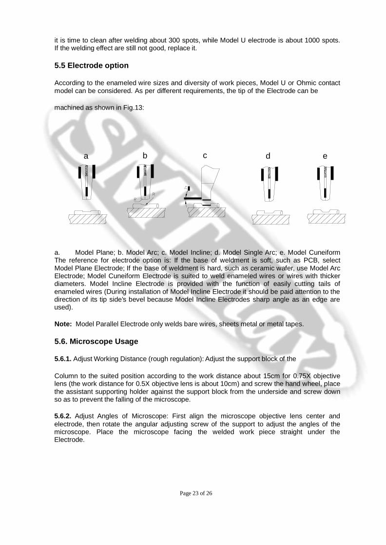
According to the enameled wire sizes and diversity of work pieces, Model U or Ohmic contact model can be considered. As per different requirements, the tip of the Electrode can be
machined as shown in Fig.13:
a b c d e
a. Model Plane; b. Model Arc; c. Model Incline; d. Model Single Arc; e. Model Cuneiform The reference for electrode option is: If the base of weldment is soft, such as PCB, select Model Plane Electrode; If the base of weldment is hard, such as ceramic wafer, use Model Arc Electrode; Model Cuneiform Electrode is suited to weld enameled wires or wires with thicker diameters. Model Incline Electrode is provided with the function of easily cutting tails of enameled wires (During installation of Model Incline Electrode it should be paid attention to the direction of its tip side’s bevel because Model Incline Electrodes sharp angle as an edge are used).
Note: Model Parallel Electrode only welds bare wires, sheets metal or metal tapes.
5.6. Microscope Usage
5.6.1. Adjust Working Distance (rough regulation): Adjust the support block of the
Column to the suited position according to the work distance about 15cm for 0.75X objective lens (the work distance for 0.5X objective lens is about 10cm) and screw the hand wheel, place the assistant supporting holder against the support block from the underside and screw down so as to prevent the falling of the microscope.
5.6.2. Adjust Angles of Microscope: First align the microscope objective lens center and electrode, then rotate the angular adjusting screw of the support to adjust the angles of the microscope. Place the microscope facing the welded work piece straight under the Electrode.

Page 24 of 26
5.6.3 Adjust Focus (fine regulation): Rotate the hand wheel of the bracket to move the microscope up and down. When the image of the observed object appears, rotate the hand wheel slightly until the presence of the clearest image is observed.
5.6.4. Adjust Diopter: Turn the diopter setting rings which are on the left eyepiece until the image in the left eye is as sharp as the image in the right.
5.6.5. Adjust Eye distance: Change the eye distance by turning the diopter setting rings so that it is suitable for observing with two eyes.
5.6.6. Adjust Magnification: The stereo-microscope has different magnification times, change the magnification times by turning the magnification change wheel. If the field of vision is still not clear, adjust the optimal focus by turning the single hand wheel (fine regulation).
IMPORTANT HINT & DESCRIPTION
a. There is an output pulse amplitude eyelet (See Fig.6) for fine regulation in the rear of Main Processor. There is a weld force eyelet (See Fig. 4.10) in the outside of the Header force display, so that there is a reserve for the Micro Welder while adjusting the consistency of the parameters.
b. When the Micro Welder leaves the factory, the load character is that the pulse amplitude output 1.50V is the calibrated point: for the weld force of the SMTMAXII-02 (common model) is 0.5N; for the weld force of the SMTMAXII-04 (high-power model) is 3.0N under the load 10mΩ.
c. The minimum and maximum of the pulse amplitude dial switch, the pulse duration dial switch and the adjusting hand wheel for weld force has already been limited. Therefore, do not overrun by force.
6. Guide of experience in Basic Operation
6.1. While installing the Electrode, the distance between the tip of the Electrode and the work piece of 5-8mm is preferable.
6.2. While welding, generally 15 times or so is better, thus the larger field of vision is seen more clearly.
6.3. During welding, the temperate pressure on the pedal is preferred. Firstly, place the Electrode on the welded enameled wires and work piece accurately by soft pressure. Then trigger the Micro Welder by slight pressure and start to perform welding. After mastering the essentials of operation adroitly, then accelerate the welding.
6.4. If cut-off of wire is needed, do not loosen the Electrode, pull the enameled wire upwards, the wire could be broken.
6.5. In order to further improve welding quality, soft welding parameters are suggested, including adjust stripping pulse and pulse climb angle; lower output voltage and lengthen
time; after finished welding do not loosen the electrode at once and let the weldment cool down by electrode excess heat.

Page 25 of 26
7. Operation Training Main Points
The operation training main points for the SMTMAX Spot Electric Welding Machine can be summarized in these words: The first step is, see; the second step is, regulation; the third step is, practice.
--The first step “see” means firstly train the operator to operate the stereo-microscope skillfully, including the rough regulation, fine regulation, angles adjustment and magnification adjustment for microscope; the operator can use his/her eyes to observe the work piece and work skillfully under the microscope.
--The second step “Regulation” means to train the operator to learn how to regulate the three welding parameters, how to judge what is unreliable welding and too big or too small parameters.
--The third step “practice” means practice as per the above guide of experience in basic operation. After 1~ hours practicing, practice makes perfect naturally.
8. Maintenance, Malfunction Analysis and Clearance
8.1. Maintenance of Welder
8.1.1. Do not open Transformer Box, Control Box and sideboards of the Header.
8.1.2. Ensure that the contact face of central axis and cupreous bearing are kept clean and dry.
8.1.3. Do not lubricate any parts if the moving component can operate smoothly.
8.2. Maintenance of Microscope
8.2.1. Place the microscope in a cool, dry place where it is free from dust.
8.2.2. Do not disassemble lens by yourself as they all have been pre-adjusted and tested. Should filth be found on the lens, it should be cleaned gently with absorbant cotton with xylene. If alcohol is used, be careful not to let it soak into the lens, or the lens will come unglued.
8.2.3. Place the microscope into cabinet or cover it when it is not being used.
8.2.4. When microscope bracket skids, after fix the axle pin of the bracket hand wheel, then turn the hand wheel oppositely. This will lock the microscope hand wheel tightly.
8.3. Malfunction Analysis of Electrode Clamp
The Electrode Clamp is an important component of the Micro Welder. If the indicator lamp of the Control Box performs normalally, yet the actual output is improper, check the Electrode Clamp first.

Page 26 of 26
8.3.1. The looseness of the fixing bolt for connection between the Electrode Clamp and two output cable heads.
8.3.2. The abrasion of insulating washer and spacer, short circuit of the left and right clamping
blocks of the Electrode Clamp.
8.3.3. Wrong installation of the Electrode.
8.3.4. If the handle of the Electrode Clamp is fastened tightly, make sure to clamp the Electrode tightly.
8.4.5. If you have poor contact on the surface of the Electrode and groove face of the Electrode
Clamp.
8.4. Other Malfunction Analysis and Clearance
8.4.1 The counter on the Transformer Box does not work.
8.4.1.1. Check the state of the power switch, loose connection of the power plug could blow the fuse .
8.4.2. Blown fuse
The fuse blows at the start-up, replace the fuse. The new fuse or replace with higher power, the fuse blows again, possibly there are failures in Control Box; please contact Micro Welding Equipment Company.
8.4.3. Malfunctions of force display for header
8.4.3.1. Check connection between the Header Cables and the socket of the main processor.
8.4.3.2. If no above malfunctions, possibly there are failures in the Control Box; please contact
Micro Welding Equipment Company.
8.4.4. Obstruction of the Header
Step on the pedal, and then loosen; yet the central axis cannot rebound promptly. Check if there is contact friction between output cable and the column. Check the central axis as well, if there is some filth on the outer edge of the central axis. Smear some metal cleaner on the fitting surface between the central axis and coppery bearing, it can work freely.
8.4.5. Abnormal Noise at Step and Rebound of the Pedal
There is some abnormal noise at step and rebound of pedal. Most likely reason is that the place at the axle pin of the pedal fulcrum is not lubricanted enough and results in over force of friction. Smear some lubricating oil on the fitting surface of the axle pin, the abnormal noise

Page 27 of 26
should be eliminated.
Page 28 of 26
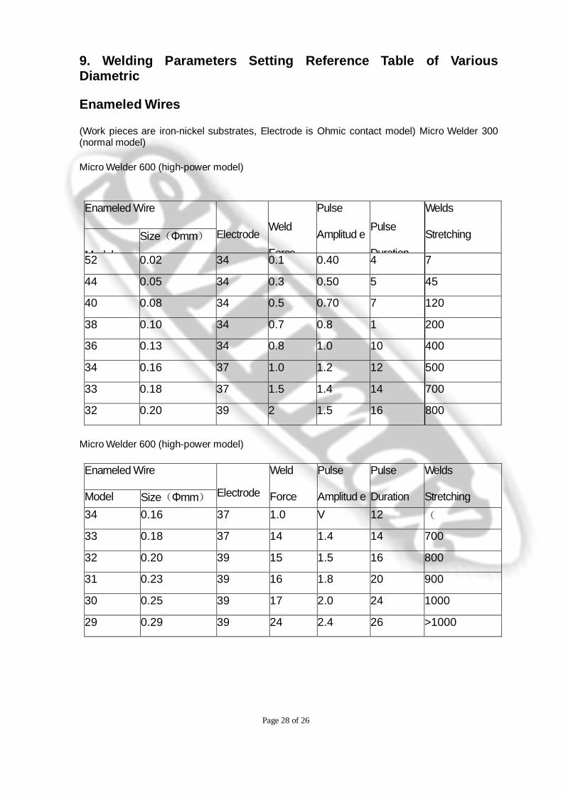
9. Welding Parameters Setting Reference Table of Various Diametric
Enameled Wires
(Work pieces are iron-nickel substrates, Electrode is Ohmic contact model) Micro Welder 300 (normal model)
Micro Welder 600 (high-power model)
Enameled Wire
Electrode
Weld
Force
Pulse
Amplitud e
Pulse
Duration
Welds
Stretching
Model Size(Φmm)
52 0.02 34 0.1 0.40 4 7
44 0.05 34 0.3 0.50 5 45
40 0.08 34 0.5 0.70 7 120
38 0.10 34 0.7 0.8 1 200
36 0.13 34 0.8 1.0 10 400
34 0.16 37 1.0 1.2 12 500
33 0.18 37 1.5 1.4 14 700
32 0.20 39 2 1.5 16 800
Micro Welder 600 (high-power model)
Enameled Wire
Electrode
Weld
Force
Pulse
Amplitud e
Pulse
Duration
Welds
Stretching
Model Size(Φmm) 34 0.16 37 1.0 V
12 (
33 0.18 37 14 1.4 14 700
32 0.20 39 15 1.5 16 800
31 0.23 39 16 1.8 20 900
30 0.25 39 17 2.0 24 1000
29 0.29 39 24 2.4 26 >1000
Page 29 of 26
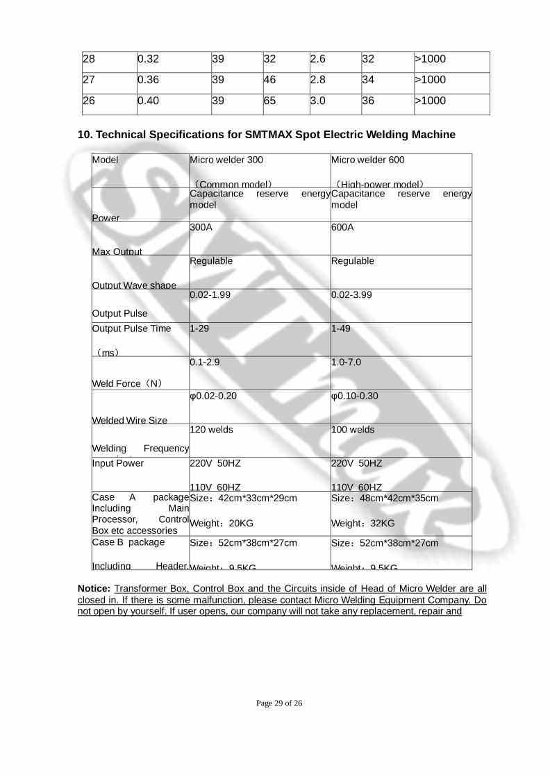
28 0.32 39 32 2.6 32 >1000
27 0.36 39 46 2.8 34 >1000
26 0.40 39 65 3.0 36 >1000
10. Technical Specifications for SMTMAX Spot Electric Welding Machine
Model Micro welder 300
(Common model)
Micro welder 600
(High-power model)
Power
Capacitance reserve energy model
Capacitance reserve energy model
Max Output
300A 600A
Output Wave shape
Regulable Regulable
Output Pulse
0.02-1.99 0.02-3.99
Output Pulse Time
(ms)
1-29 1-49
Weld Force(N)
0.1-2.9 1.0-7.0
Welded Wire Size
φ0.02-0.20 φ0.10-0.30
Welding Frequency i t
120 welds 100 welds
Input Power 220V 50HZ
110V 60HZ
220V 50HZ
110V 60HZ Case A package Including Main Processor, Control Box etc accessories
Size:42cm*33cm*29cm
Weight:20KG
Size:48cm*42cm*35cm
Weight:32KG
Case B package
Including Header,
Size:52cm*38cm*27cm
Weight:9 5KG
Size:52cm*38cm*27cm
Weight:9 5KG
Notice: Transformer Box, Control Box and the Circuits inside of Head of Micro Welder are all closed in. If there is some malfunction, please contact Micro Welding Equipment Company. Do not open by yourself. If user opens, our company will not take any replacement, repair and

Page 30 of 26
after-sales service of this Micro Welder.