Embed Size (px)
Citation preview
SMS Tutorials SRH-2D - Gates
Page 1 of 10
SMS 12.2 Tutorial SRH-2D – Gates
SMS v. 12.2
Prerequisites
SRH-2D
Objectives
This tutorial demonstrates the process of modeling Gates in SRH-2D. The “SRH-2D” tutorial should have
been completed before attempting this one. All files for this tutorial are found in the “Data” folder within
the “ SRH2D_Gate” folder.
Requirements
SRH-2D
Mesh Module
Scatter Module
Map Module
Time
15–20 minutes
SMS Tutorials SRH-2D - Gates
Page 2 of 10
1 Model Overview
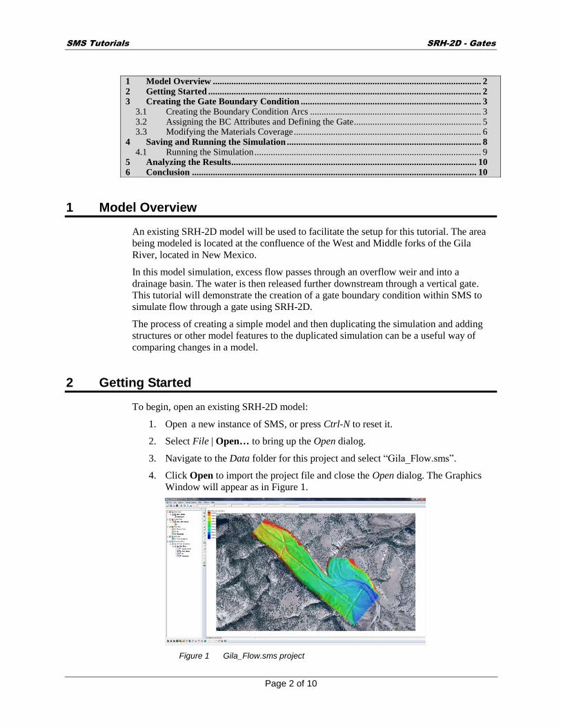
An existing SRH-2D model will be used to facilitate the setup for this tutorial. The area
being modeled is located at the confluence of the West and Middle forks of the Gila
River, located in New Mexico.
In this model simulation, excess flow passes through an overflow weir and into a
drainage basin. The water is then released further downstream through a vertical gate.
This tutorial will demonstrate the creation of a gate boundary condition within SMS to
simulate flow through a gate using SRH-2D.
The process of creating a simple model and then duplicating the simulation and adding
structures or other model features to the duplicated simulation can be a useful way of
comparing changes in a model.
2 Getting Started
To begin, open an existing SRH-2D model:
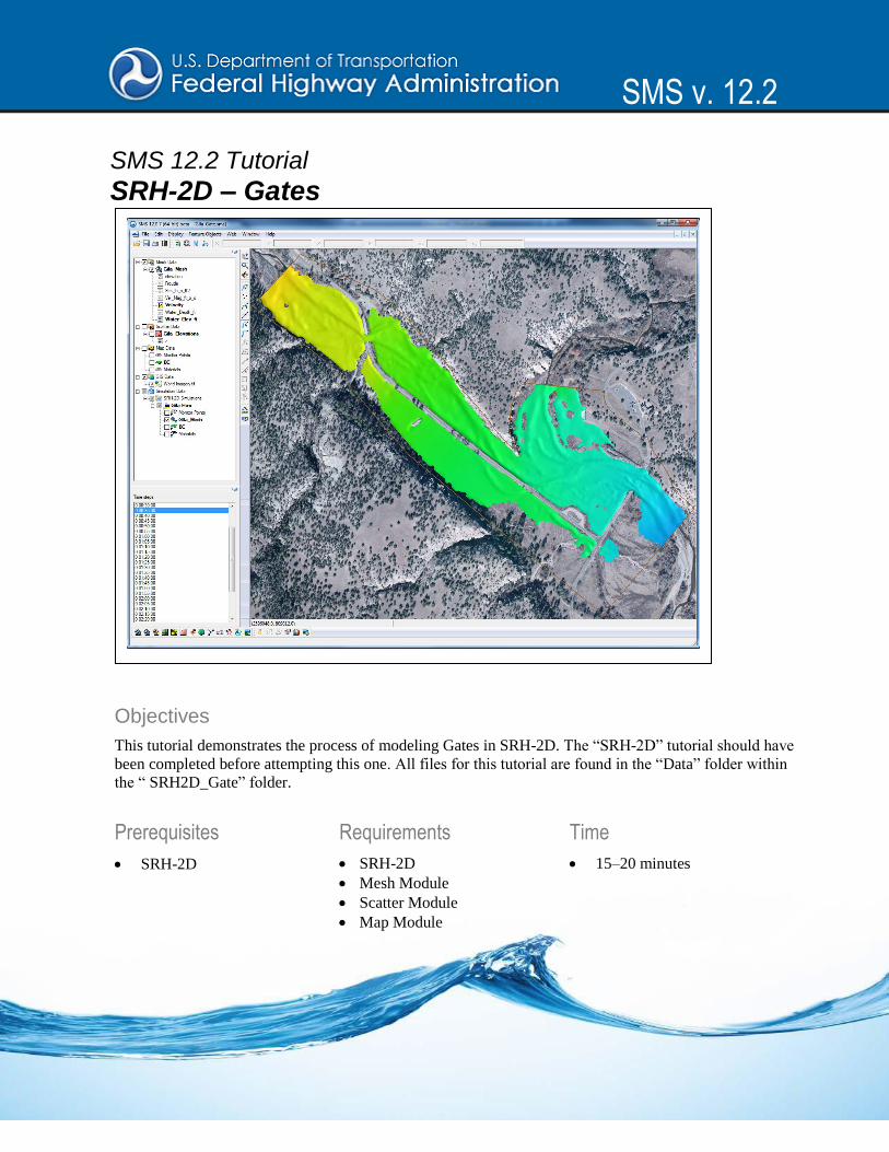
1. Open a new instance of SMS, or press Ctrl-N to reset it.
2. Select File | Open… to bring up the Open dialog.
3. Navigate to the Data folder for this project and select “Gila_Flow.sms”.
4. Click Open to import the project file and close the Open dialog. The Graphics
Window will appear as in Figure 1.
Figure 1 Gila_Flow.sms project
1 Model Overview .................................................................................................................... 2 2 Getting Started ...................................................................................................................... 2 3 Creating the Gate Boundary Condition .............................................................................. 3
3.1 Creating the Boundary Condition Arcs .......................................................................... 3 3.2 Assigning the BC Attributes and Defining the Gate....................................................... 5 3.3 Modifying the Materials Coverage ................................................................................. 6
4 Saving and Running the Simulation .................................................................................... 8 4.1 Running the Simulation .................................................................................................. 9
5 Analyzing the Results .......................................................................................................... 10 6 Conclusion ........................................................................................................................... 10

SMS Tutorials SRH-2D - Gates
Page 3 of 10
3 Creating the Gate Boundary Condition
Gate boundary conditions are defined by creating a pair of arcs in the boundary condition
coverage, one on the upstream face and one on the downstream face of the gate structure.
A polygon specifying the area between the arcs is also created in the materials coverage
and defined as an unassigned material type. The arcs are then defined as a gate in SMS
and attributes of the gate are specified.
3.1 Creating the Boundary Condition Arcs
The first step is to create arcs within the boundary condition coverage that represent the
gate structure near the intersection of the two roads as displayed in Figure 2.
Figure 2 Zoomed in on the gate location
1. Zoom into the gate location shown in the Figure 2 inset.
2. Select Display | Display Options… to open the Display Options dialog.
3. Select “2D Mesh” from the list on the left.
4. In the 2D Mesh tab, turn on Elements.
5. Select OK to exit the Display Options dialog.
6. In the Project Explorer, select the “ BC” coverage to make it active.
7. Using the Create Feature Arc tool, create two arcs, one on each side of the
road (Figure 3). These arcs will define the upstream and downstream faces of the
gate boundary condition.
In most cases, both a gate structure and a culvert would be included in a scenario such as
this. For simplification purposes, this tutorial uses only a 1D gate with flow computed
which implies the existence of a culvert sufficiently large as to not impede flow under the
road.
SMS Tutorials SRH-2D - Gates
Page 4 of 10
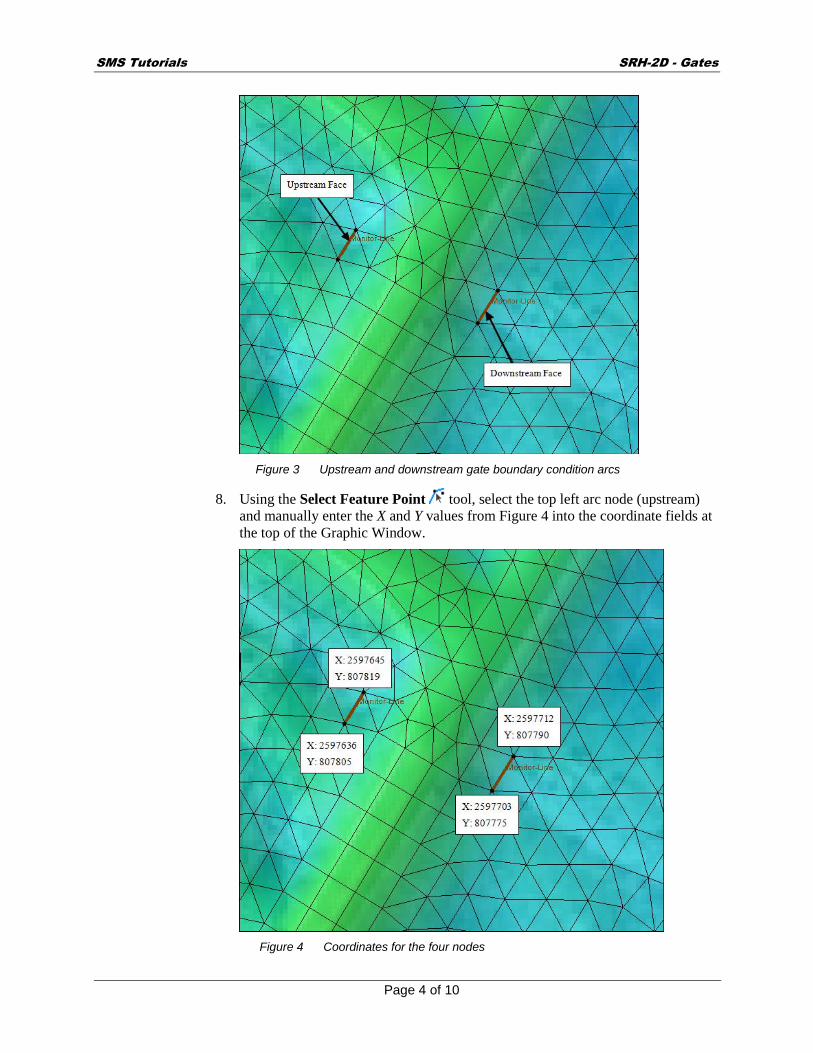
Figure 3 Upstream and downstream gate boundary condition arcs
8. Using the Select Feature Point tool, select the top left arc node (upstream)
and manually enter the X and Y values from Figure 4 into the coordinate fields at
the top of the Graphic Window.
Figure 4 Coordinates for the four nodes

SMS Tutorials SRH-2D - Gates
Page 5 of 10
9. Repeat step 8 for the remaining nodes, and using the data from Figure 4.
10. If any vertices exist along these arcs, they should be selected and deleted using
the Select Feature Vertex tool and pressing the Delete key.
3.2 Assigning the BC Attributes and Defining the Gate
The next step in creating a boundary condition is to specify the boundary condition (BC)
type and define the attributes of the gate. 1D gates within SRH-2D simulate the flow of
an underflow gate such as a vertical lift gate or radial gate. These types of gates behave as
an orifice when the water surface is above the top of the gate opening and as a weir when
the water surface is below the top of the gate opening.
If the gate to be modeled is an overflow gate, such as a flap gate, sector gate, or roller
gate, these can simply be modeled as a weir structure in SRH-2D. The gate in this tutorial
will be defined as a vertical underflow gate.
To do this, do the following:
1. Using the Select Feature Arc tool, select the upstream (leftmost) arc and take
note of the ID for this arc (displayed at the bottom of the Graphics Window).
2. Hold the Shift key and select the downstream arc so that both of the arcs are
selected.
3. Right-click on either arc and select Assign Linear BC... to bring up the SRH-2D
Linear BC dialog.
4. Select “Gate” from the Type drop-down.
5. Note the Role assignment of “gate upstream” and “gate downstream” to the two
arcs, associated with the Object ID values. If the Object ID displayed for gate
upstream is not the same as noted above in step 1, switch the associations using
the drop-down in the Role column.
6. Select “ft” from the Units drop-down.
7. Scroll down and enter “5649” in the Crest Elevation field. This represents the
elevation of the base upon which the gate closes, or channel bottom.
8. Enter “3” in the Height of Gate Opening (Hg). This represents the opening
measured vertically from the base of the structure to the top of the gate opening
as shown in Figure 5.

SMS Tutorials SRH-2D - Gates
Page 6 of 10
Figure 5 Height of gate opening
9. Enter “16” for Width of Gate Opening. This represents the horizontal width of the
gate opening.
10. Enter “0.61” for Contract Coefficient with Underflow Orifice. This is used to
calculate the discharge coefficient, which is then used to determine the flow
under the gate.
11. Select “Gravel” from the Type drop-down.
12. Select OK to exit the SRH-2D Linear BC dialog.
3.3 Modifying the Materials Coverage
In order to properly define a gate boundary condition in SMS, the materials coverage
must also be modified. SMS requires that the material type of the elements between the
two faces of the gate be specified as “Unassigned”. Any element with an unassigned
material type will be defined as a “No-flow”/ inactive element.
1. Turn off “ Mesh Data” and “ GIS Data” in the Project Explorer.
2. Turn on the “ Materials” coverage and select it to make it active.
3. Using the Create Feature Arc tool, click out a rectilinear arc that encloses
the area between the two gate arcs (Figure 6).Use the visible inactive gate arcs
from the “BC” coverage as a guide when drawing the enclosed area.

SMS Tutorials SRH-2D - Gates
Page 7 of 10
Figure 6 Enclosed area between gate arcs
4. Select Feature Objects | Build Polygons. Three polygons will be created: one on
each side of the road and one directly beneath the road.
5. Using the Select Feature Polygon tool, select the three polygons by holding
down the Shift key and selecting them.
6. Right-click and choose Assign Material Properties to bring up the Assign
Material Properties dialog.
7. Select “unassigned” from the Materials list on the left.
8. Click OK to close the Assign Material Properties dialog.
The Graphics Window should appear similar to Figure 7. Some of the displays for the
materials may differ, but the material types should be the same. The dotted lines are from
the shift preview and can be turned off by pressing Shift + Q. The shift preview simply
shows how the materials will be assigned to the mesh.

SMS Tutorials SRH-2D - Gates
Page 8 of 10
Figure 7 Edited material coverage
4 Saving and Running the Simulation
Now that the gate structure has been created and defined, set up the simulation by doing
the following:
1. Right-click on the “ Gila Flow” simulation in the Project Explorer and choose
Model Control… to bring up the Model Control dialog.
2. Enter “Gate_Flow” as the Case Name.
3. Click OK to accept all other default settings and close the Model Control dialog.
To save the project, do the following:
1. Select File | Save as… to bring up the Save As dialog.
2. Enter “Gila_Gate.sms” in the File name field
3. Select “Project Files (*.sms)” from the Save as type drop-down.
4. Click on Save to save the project and close the Save As dialog.

SMS Tutorials SRH-2D - Gates
Page 9 of 10
4.1 Running the Simulation
Now the simulation can be run:
1. Right-click on the “Gila Flow” simulation and choose Save, Export, and
Launch SRH-2D.
2. Click OK if a warning is displayed stating that the “Materials” coverage will be
renumbered before exporting. This brings up the SRH-2D: Gila Flow dialog and
a wrapper window with three windows (Figure 8).
Figure 8 Wrapper window showing SRH-2D running status
When saving, exporting and launching SRH-2D, SMS will initialize and run pre-SRH,
the SRH-2D preprocessor. The run process may take several minutes, depending on the
processing capabilities of the computer running it. When pre-SRH has finished running,
SRH-2D will begin to run.
3. Once SRH-2D is finished running, a small dialog will appear. Click Yes to close
the wrapper window and return to the SRH-2D: Gila Flow dialog.
4. Turn on Load Solution and click Exit to close the SRH-2D: Gila Flow dialog.
The solution datasets will now be listed in the Project Explorer under
“Gila_Mesh”.
5. Frame the project.
6. Turn on “ Mesh Data” and “ GIS Data” in the Project Explorer.
7. Turn off the “ Materials” and “ BC” coverages in the Project Explorer.
8. Select Display | Display Options… to bring up the Display Options dialog.
9. Select “2D Mesh” from the list on the left.
10. On the 2D Mesh tab, turn off Elements.
11. Click OK to close the Display Options dialog.

SMS Tutorials SRH-2D - Gates
Page 10 of 10
5 Analyzing the Results
The simulation goes through several phases that will be discussed in this section.
1. Select the “ Water_Elev_ft” mesh dataset to make it active.
2. Select the “00:00:02” time step to make it the active time step.
3. Step through the simulation time steps while observing the water surface
elevation displayed. From times “00:00:02” until “00:30:00” the water flows
over the weir and into the overflow basin, approaching the gate.
4. Select time “00:35:00” and observe that the water has reached the gate and is
now flowing through the gate.
5. Zoom in close enough to easily view the contours around the gate structure.
The crest elevation was specified as 5649 feet and the height of the gate opening was
specified as three feet. This means that, until the water surface elevation reaches an
elevation of 5652 feet, SRH-2D will compute the flow through the structure using a weir
flow equation.
Once the water surface elevation reaches an elevation of 5652 feet, SRH-2D will begin to
compute the flow through the structure as a submerged gate.
6. Right-click on the “ Water_Elev_ft” dataset and choose Dataset Contour
Options… to bring up the Dataset Contour Options – Water_Elev_ft dialog.
7. In the Data range section, turn on Specify a range.
8. Enter “5649” in the Min field and “5652” in the Max field.
9. Select OK to close the Dataset Contour Options – Water_Elev_ft dialog. Notice
that at time “00:35:00”, the water surface elevation is still below 5652 ft along
the gate arc.
10. Select the time step “00:40:00”. Notice that the water surface elevation is now
equal to or greater than 5652 ft signifying that the gate has been submerged and
flows are now being computed as a submerged gate.
11. Continue to step through the time steps. Notice that somewhere around time
01:30:00 the water surface elevation begins to drop below 5652 ft signifying that
the gate is no longer submerged and it has entered the weir flow regime once
again.
12. Continue to toggle through the time steps. Notice that the water surface elevation
continues to drop as water flows under the gate.
6 Conclusion
This concludes the “SRH-2D – Gates”1 tutorial. If desired, further analysis could be
performed by the user to evaluate other aspects of the model. Continue to experiment
with the SMS interface or may quit the program.
1 This tutorial was developed by Aquaveo, LLC under contract with the Federal Highway Administration.