Embed Size (px)
Citation preview
Smile analysis and smile design have becomekey elements of orthodontic diagnosis and
treatment planning over the last decade.1-3 Recentadvances in technology now permit the clinicianto measure dynamic lip-tooth relationships andincorporate that information into the orthodonticproblem list and biomechanical plan. Digitalvideography is particularly useful in both smileanalysis and in doctor/patient communication.Smile design is a multifactorial process, withclinical success determined by an understandingof the patient’s soft-tissue treatment limitationsand the extent to which orthodontics or multidis-ciplinary treatment can satisfy the patient’s andorthodontist’s esthetic goals.
Anatomy of the Smile
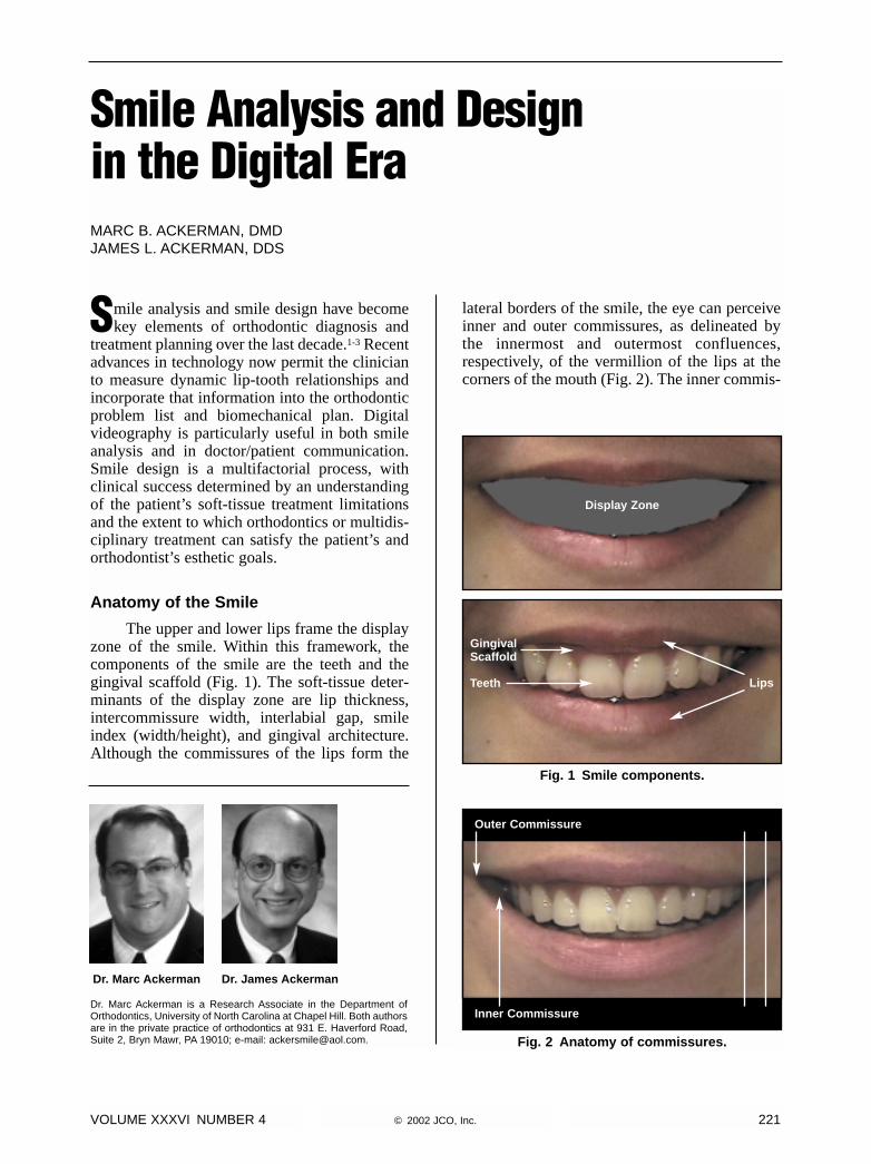
The upper and lower lips frame the displayzone of the smile. Within this framework, thecomponents of the smile are the teeth and thegingival scaffold (Fig. 1). The soft-tissue deter-minants of the display zone are lip thickness,intercommissure width, interlabial gap, smileindex (width/height), and gingival architecture.Although the commissures of the lips form the
lateral borders of the smile, the eye can perceiveinner and outer commissures, as delineated bythe innermost and outermost confluences,respectively, of the vermillion of the lips at thecorners of the mouth (Fig. 2). The inner commis-
VOLUME XXXVI NUMBER 4 © 2002 JCO, Inc. 221
Smile Analysis and Designin the Digital EraMARC B. ACKERMAN, DMDJAMES L. ACKERMAN, DDS
Dr. Marc Ackerman is a Research Associate in the Department ofOrthodontics, University of North Carolina at Chapel Hill. Both authorsare in the private practice of orthodontics at 931 E. Haverford Road,Suite 2, Bryn Mawr, PA 19010; e-mail: [email protected].
Dr. Marc Ackerman Dr. James Ackerman
Fig. 1 Smile components.
Fig. 2 Anatomy of commissures.
GingivalScaffold
Outer Commissure
Inner Commissure
Teeth Lips
Display Zone
sure is formed by the mucosa overlying the buc-cinator muscle where it inserts with the orbicu-laris oris muscle fibers at the modiolus.
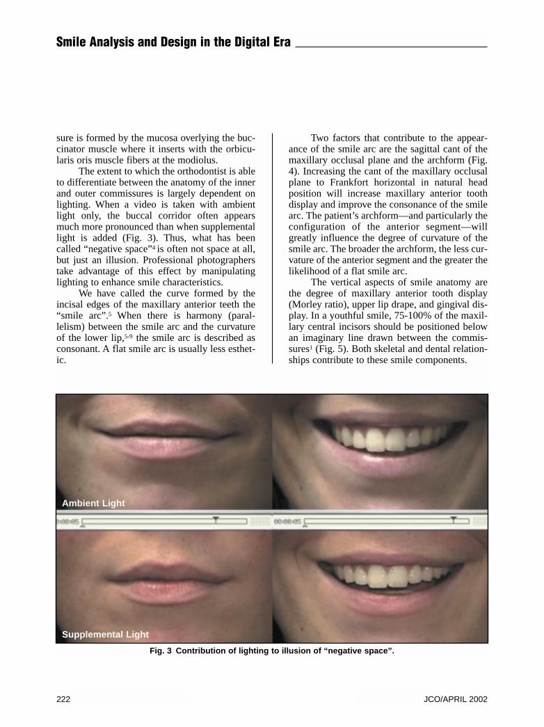
The extent to which the orthodontist is ableto differentiate between the anatomy of the innerand outer commissures is largely dependent onlighting. When a video is taken with ambientlight only, the buccal corridor often appearsmuch more pronounced than when supplementallight is added (Fig. 3). Thus, what has beencalled “negative space”4 is often not space at all,but just an illusion. Professional photographerstake advantage of this effect by manipulatinglighting to enhance smile characteristics.
We have called the curve formed by theincisal edges of the maxillary anterior teeth the“smile arc”.5 When there is harmony (paral-lelism) between the smile arc and the curvatureof the lower lip,5-9 the smile arc is described asconsonant. A flat smile arc is usually less esthet-ic.
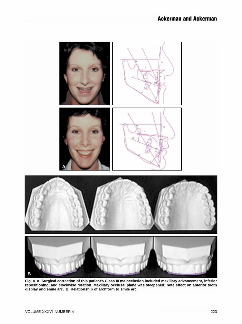
Two factors that contribute to the appear-ance of the smile arc are the sagittal cant of themaxillary occlusal plane and the archform (Fig.4). Increasing the cant of the maxillary occlusalplane to Frankfort horizontal in natural headposition will increase maxillary anterior toothdisplay and improve the consonance of the smilearc. The patient’s archform—and particularly theconfiguration of the anterior segment—willgreatly influence the degree of curvature of thesmile arc. The broader the archform, the less cur-vature of the anterior segment and the greater thelikelihood of a flat smile arc.
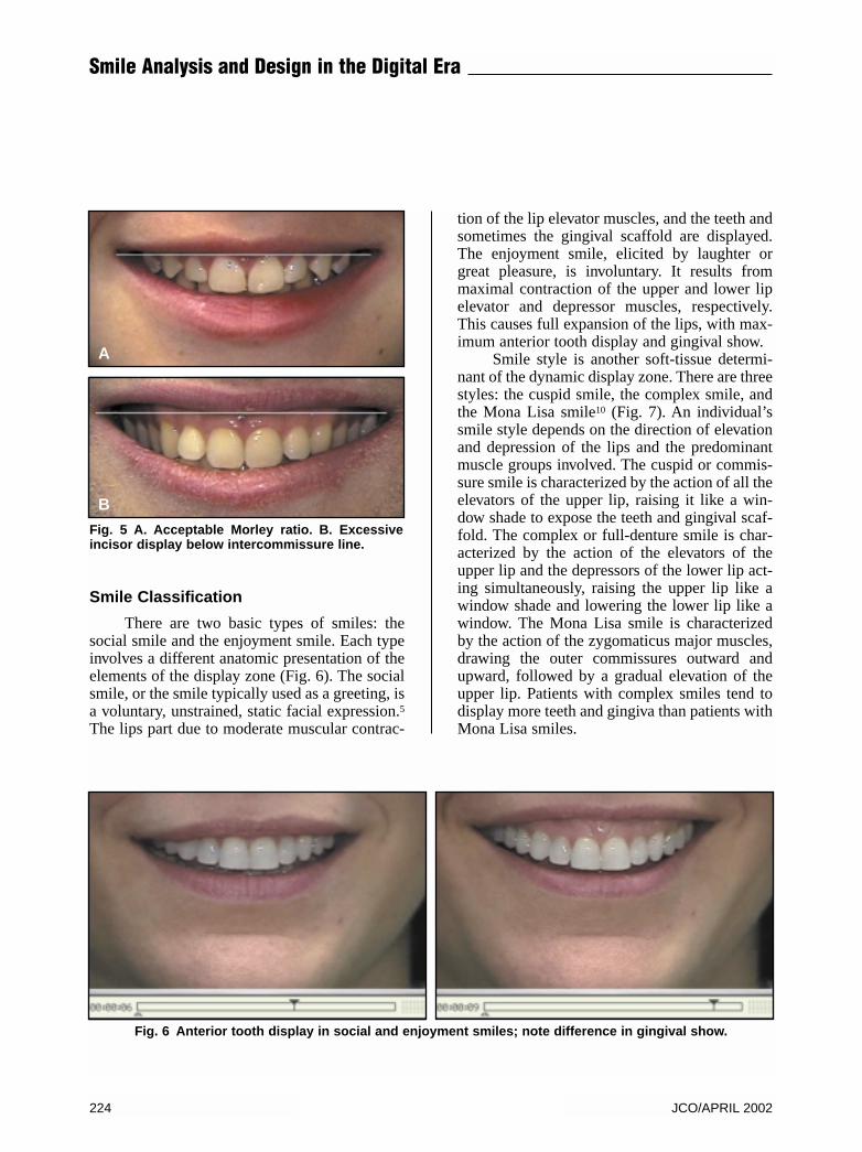
The vertical aspects of smile anatomy arethe degree of maxillary anterior tooth display(Morley ratio), upper lip drape, and gingival dis-play. In a youthful smile, 75-100% of the maxil-lary central incisors should be positioned belowan imaginary line drawn between the commis-sures1 (Fig. 5). Both skeletal and dental relation-ships contribute to these smile components.
222 JCO/APRIL 2002
Smile Analysis and Design in the Digital Era
Fig. 3 Contribution of lighting to illusion of “negative space”.
Ambient Light
Supplemental Light
VOLUME XXXVI NUMBER 4 223
Ackerman and Ackerman
Fig. 4 A. Surgical correction of this patient’s Class III malocclusion included maxillary advancement, inferiorrepositioning, and clockwise rotation. Maxillary occlusal plane was steepened; note effect on anterior toothdisplay and smile arc. B. Relationship of archform to smile arc.
B
A
Smile Classification
There are two basic types of smiles: thesocial smile and the enjoyment smile. Each typeinvolves a different anatomic presentation of theelements of the display zone (Fig. 6). The socialsmile, or the smile typically used as a greeting, isa voluntary, unstrained, static facial expression.5The lips part due to moderate muscular contrac-
tion of the lip elevator muscles, and the teeth andsometimes the gingival scaffold are displayed.The enjoyment smile, elicited by laughter orgreat pleasure, is involuntary. It results frommaximal contraction of the upper and lower lipelevator and depressor muscles, respectively.This causes full expansion of the lips, with max-imum anterior tooth display and gingival show.
Smile style is another soft-tissue determi-nant of the dynamic display zone. There are threestyles: the cuspid smile, the complex smile, andthe Mona Lisa smile10 (Fig. 7). An individual’ssmile style depends on the direction of elevationand depression of the lips and the predominantmuscle groups involved. The cuspid or commis-sure smile is characterized by the action of all theelevators of the upper lip, raising it like a win-dow shade to expose the teeth and gingival scaf-fold. The complex or full-denture smile is char-acterized by the action of the elevators of theupper lip and the depressors of the lower lip act-ing simultaneously, raising the upper lip like awindow shade and lowering the lower lip like awindow. The Mona Lisa smile is characterizedby the action of the zygomaticus major muscles,drawing the outer commissures outward andupward, followed by a gradual elevation of theupper lip. Patients with complex smiles tend todisplay more teeth and gingiva than patients withMona Lisa smiles.
Fig. 5 A. Acceptable Morley ratio. B. Excessiveincisor display below intercommissure line.
A
B
Fig. 6 Anterior tooth display in social and enjoyment smiles; note difference in gingival show.
224 JCO/APRIL 2002
Smile Analysis and Design in the Digital Era
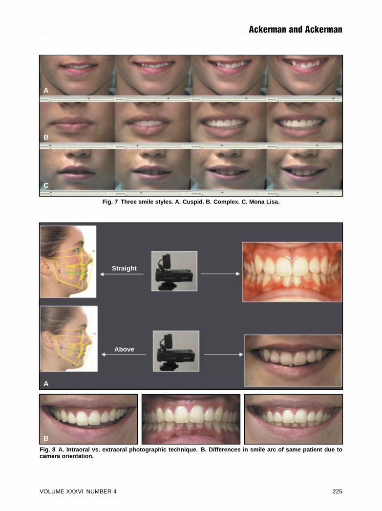
Fig. 7 Three smile styles. A. Cuspid. B. Complex. C. Mona Lisa.
A
B
C
Fig. 8 A. Intraoral vs. extraoral photographic technique. B. Differences in smile arc of same patient due tocamera orientation.
A
B
VOLUME XXXVI NUMBER 4 225
Ackerman and Ackerman
Straight
Above
Smile Capture Method
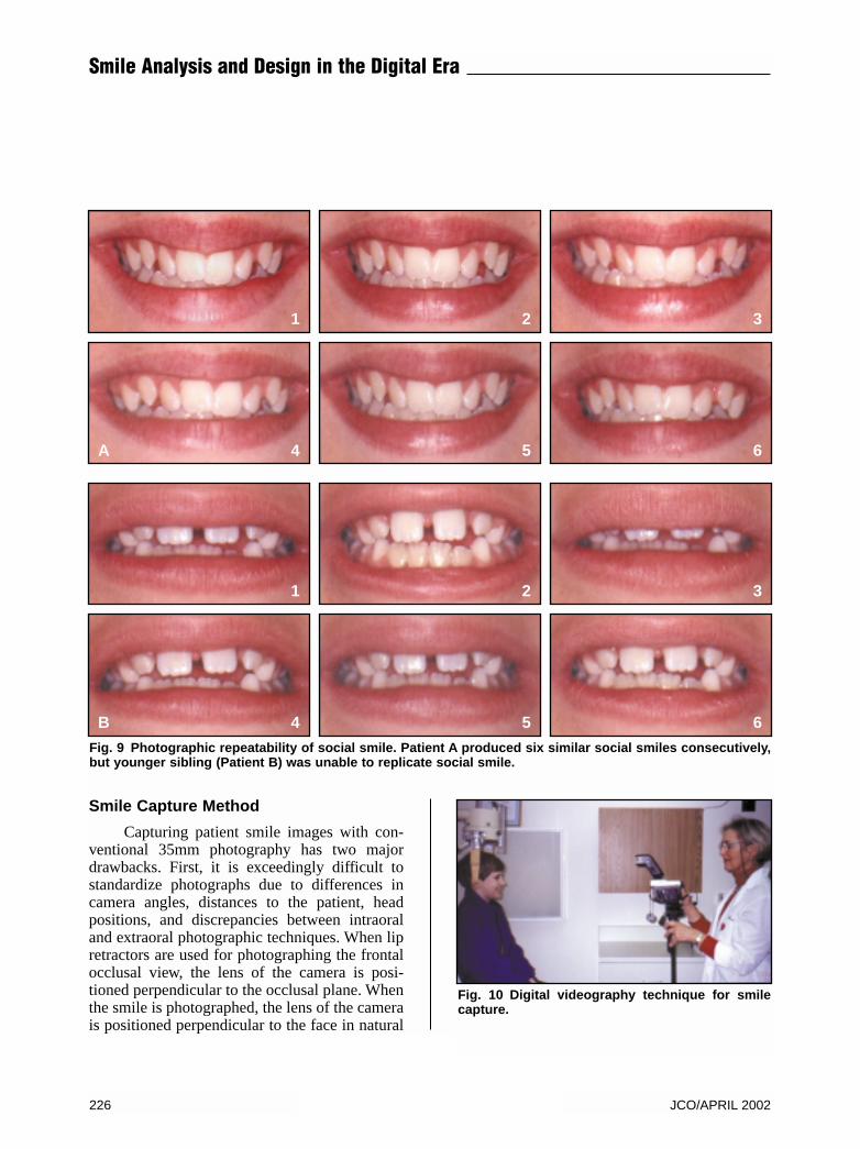
Capturing patient smile images with con-ventional 35mm photography has two majordrawbacks. First, it is exceedingly difficult tostandardize photographs due to differences incamera angles, distances to the patient, headpositions, and discrepancies between intraoraland extraoral photographic techniques. When lipretractors are used for photographing the frontalocclusal view, the lens of the camera is posi-tioned perpendicular to the occlusal plane. Whenthe smile is photographed, the lens of the camerais positioned perpendicular to the face in natural
Fig. 9 Photographic repeatability of social smile. Patient A produced six similar social smiles consecutively,but younger sibling (Patient B) was unable to replicate social smile.
Fig. 10 Digital videography technique for smilecapture.
226 JCO/APRIL 2002
Smile Analysis and Design in the Digital Era
A
1
4
1
4
2
5
2
5
3
6
3
6B
head position, effectively shooting from abovethe occlusal plane. The result is a difference inappearance of the smile arc in those two views(Fig. 8A). Using the simulation method ofGunther Blaseio (Quick Ceph Image Pro*), theintraoral photograph can be “pasted” into thesmile display zone taken in natural head positionto demonstrate the discrepancy resulting fromthe difference in camera orientation (Fig. 8B).Second, it is impossible to repeat the social smileexactly during one photography session, muchless over a longer period of time. When severalconsecutive smile photographs are taken at theorthodontic records visit, the clinician will oftennote variations in the smile (Fig. 9). In children,this phenomenon is most likely due to relativelylate maturation of the social smile.
Standardized digital videography allowsthe clinician to capture a patient’s speech, oraland pharyngeal function, and smile at the same
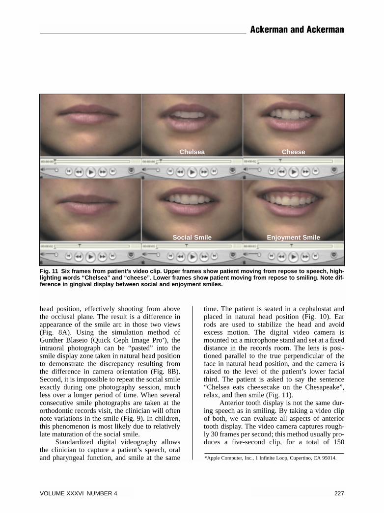
time. The patient is seated in a cephalostat andplaced in natural head position (Fig. 10). Earrods are used to stabilize the head and avoidexcess motion. The digital video camera ismounted on a microphone stand and set at a fixeddistance in the records room. The lens is posi-tioned parallel to the true perpendicular of theface in natural head position, and the camera israised to the level of the patient’s lower facialthird. The patient is asked to say the sentence“Chelsea eats cheesecake on the Chesapeake”,relax, and then smile (Fig. 11).
Anterior tooth display is not the same dur-ing speech as in smiling. By taking a video clipof both, we can evaluate all aspects of anteriortooth display. The video camera captures rough-ly 30 frames per second; this method usually pro-duces a five-second clip, for a total of 150
*Apple Computer, Inc., 1 Infinite Loop, Cupertino, CA 95014.
Fig. 11 Six frames from patient’s video clip. Upper frames show patient moving from repose to speech, high-lighting words “Chelsea” and “cheese”. Lower frames show patient moving from repose to smiling. Note dif-ference in gingival display between social and enjoyment smiles.
VOLUME XXXVI NUMBER 4 227
Ackerman and Ackerman
Chelsea Cheese
Social Smile Enjoyment Smile
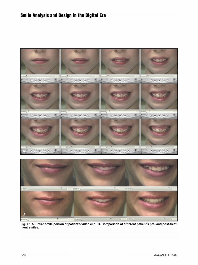
Fig. 12 A. Entire smile portion of patient’s video clip. B. Comparison of different patient’s pre- and post-treat-ment smiles.
A
B
228 JCO/APRIL 2002
Smile Analysis and Design in the Digital Era
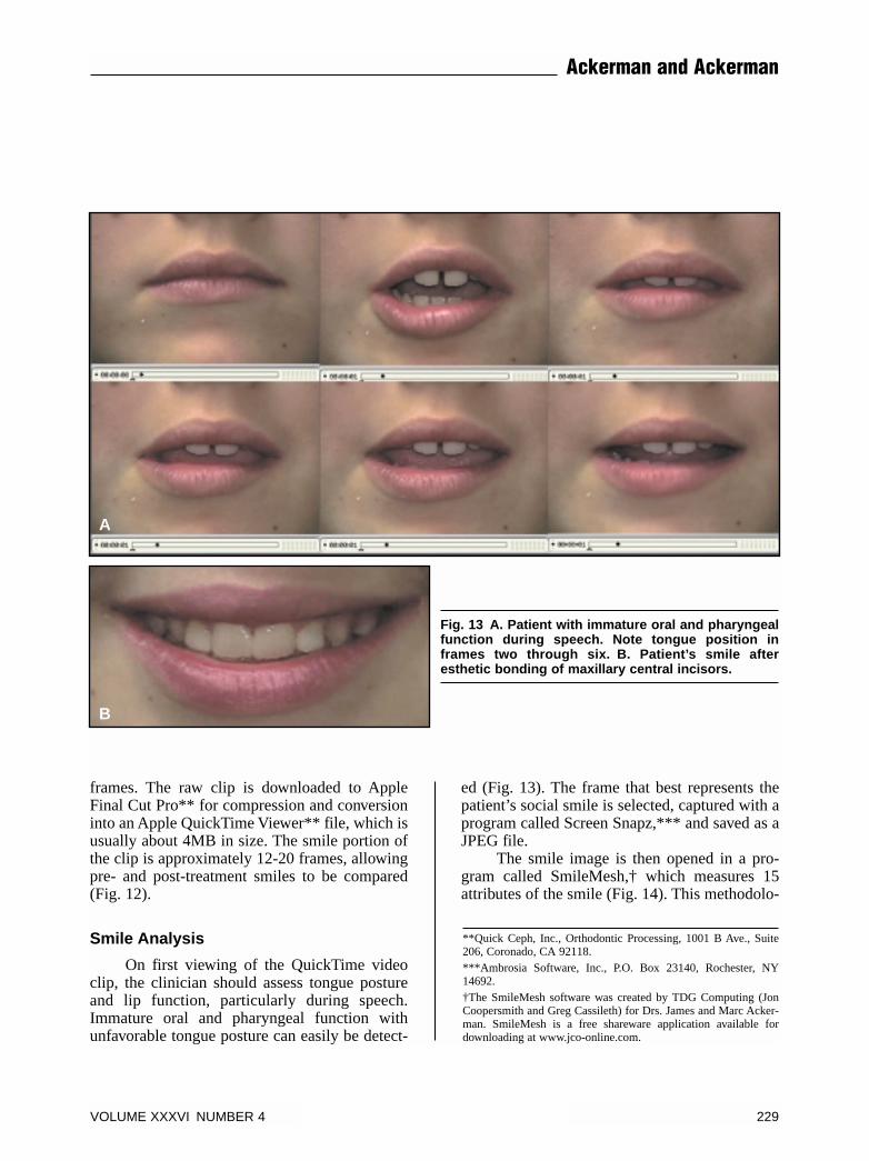
frames. The raw clip is downloaded to AppleFinal Cut Pro** for compression and conversioninto an Apple QuickTime Viewer** file, which isusually about 4MB in size. The smile portion ofthe clip is approximately 12-20 frames, allowingpre- and post-treatment smiles to be compared(Fig. 12).
Smile Analysis
On first viewing of the QuickTime videoclip, the clinician should assess tongue postureand lip function, particularly during speech.Immature oral and pharyngeal function withunfavorable tongue posture can easily be detect-
ed (Fig. 13). The frame that best represents thepatient’s social smile is selected, captured with aprogram called Screen Snapz,*** and saved as aJPEG file.
The smile image is then opened in a pro-gram called SmileMesh,† which measures 15attributes of the smile (Fig. 14). This methodolo-
Fig. 13 A. Patient with immature oral and pharyngealfunction during speech. Note tongue position inframes two through six. B. Patient’s smile afteresthetic bonding of maxillary central incisors.
A
B
**Quick Ceph, Inc., Orthodontic Processing, 1001 B Ave., Suite206, Coronado, CA 92118.***Ambrosia Software, Inc., P.O. Box 23140, Rochester, NY14692.†The SmileMesh software was created by TDG Computing (JonCoopersmith and Greg Cassileth) for Drs. James and Marc Acker-man. SmileMesh is a free shareware application available fordownloading at www.jco-online.com.
VOLUME XXXVI NUMBER 4 229
Ackerman and Ackerman
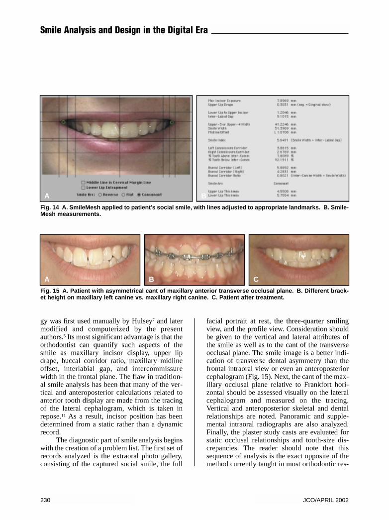
gy was first used manually by Hulsey7 and latermodified and computerized by the presentauthors.5 Its most significant advantage is that theorthodontist can quantify such aspects of thesmile as maxillary incisor display, upper lipdrape, buccal corridor ratio, maxillary midlineoffset, interlabial gap, and intercommissurewidth in the frontal plane. The flaw in tradition-al smile analysis has been that many of the ver-tical and anteroposterior calculations related toanterior tooth display are made from the tracingof the lateral cephalogram, which is taken inrepose.11 As a result, incisor position has beendetermined from a static rather than a dynamicrecord.
The diagnostic part of smile analysis beginswith the creation of a problem list. The first set ofrecords analyzed is the extraoral photo gallery,consisting of the captured social smile, the full
facial portrait at rest, the three-quarter smilingview, and the profile view. Consideration shouldbe given to the vertical and lateral attributes ofthe smile as well as to the cant of the transverseocclusal plane. The smile image is a better indi-cation of transverse dental asymmetry than thefrontal intraoral view or even an anteroposteriorcephalogram (Fig. 15). Next, the cant of the max-illary occlusal plane relative to Frankfort hori-zontal should be assessed visually on the lateralcephalogram and measured on the tracing.Vertical and anteroposterior skeletal and dentalrelationships are noted. Panoramic and supple-mental intraoral radiographs are also analyzed.Finally, the plaster study casts are evaluated forstatic occlusal relationships and tooth-size dis-crepancies. The reader should note that thissequence of analysis is the exact opposite of themethod currently taught in most orthodontic res-
A B
Fig. 14 A. SmileMesh applied to patient’s social smile, with lines adjusted to appropriate landmarks. B. Smile-Mesh measurements.
Fig. 15 A. Patient with asymmetrical cant of maxillary anterior transverse occlusal plane. B. Different brack-et height on maxillary left canine vs. maxillary right canine. C. Patient after treatment.
A B C
230 JCO/APRIL 2002
Smile Analysis and Design in the Digital Era
idency programs.The smile component of the orthodontic
problem list consists of descriptive terms such as
inadequate maxillary incisor display, unfavorableMorley ratio, excess gingival show, flat orreverse smile arc, asymmetric cant of the maxil-
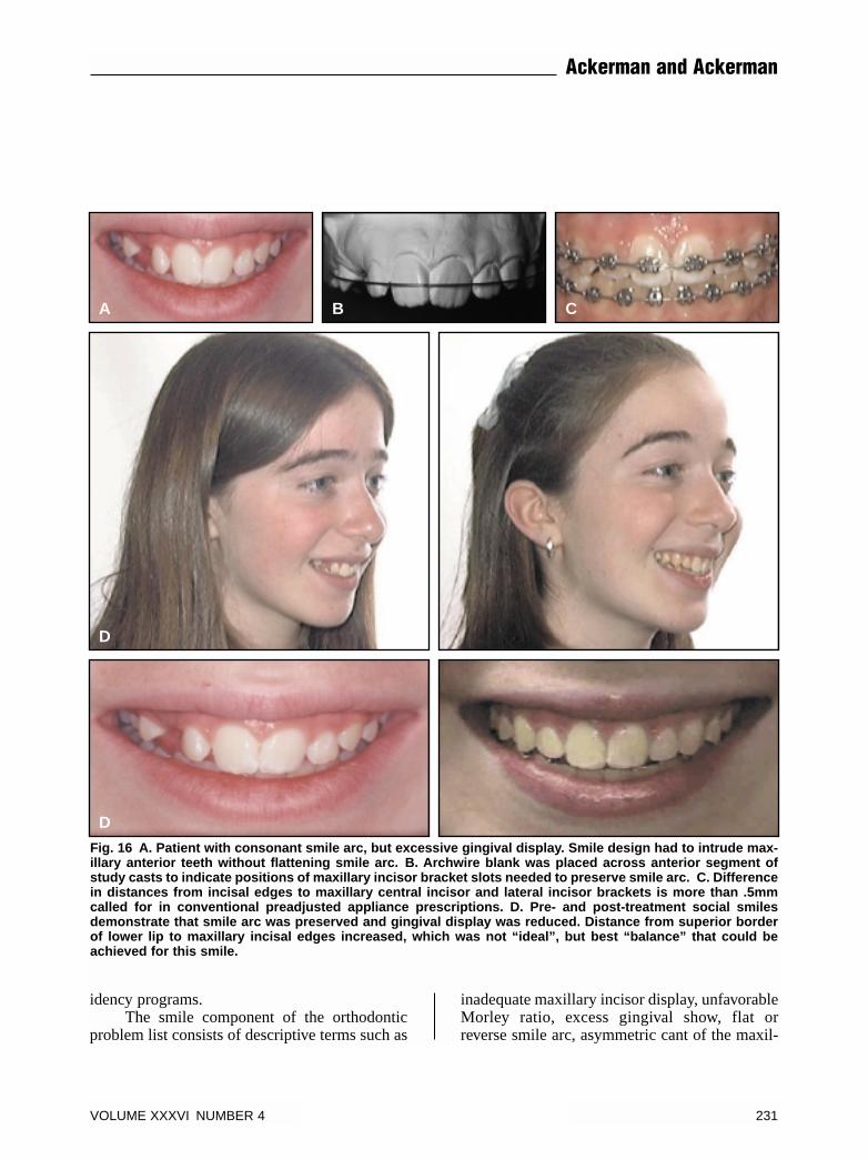
Fig. 16 A. Patient with consonant smile arc, but excessive gingival display. Smile design had to intrude max-illary anterior teeth without flattening smile arc. B. Archwire blank was placed across anterior segment ofstudy casts to indicate positions of maxillary incisor bracket slots needed to preserve smile arc. C. Differencein distances from incisal edges to maxillary central incisor and lateral incisor brackets is more than .5mmcalled for in conventional preadjusted appliance prescriptions. D. Pre- and post-treatment social smilesdemonstrate that smile arc was preserved and gingival display was reduced. Distance from superior borderof lower lip to maxillary incisal edges increased, which was not “ideal”, but best “balance” that could beachieved for this smile.
A B C
D
D
VOLUME XXXVI NUMBER 4 231
Ackerman and Ackerman
lary anterior transverse occlusal plane, and oblit-erated buccal corridors, to name a few. The clin-ician should rank these smile attributes in orderof their importance in creating a balanced smile.The final problem list will help the orthodontistto assess the viability of different treatmentoptions and select the appropriate mechanothera-py for optimal smile design.
Smile Design
It must be understood that there is no uni-versal “ideal” smile. The most important estheticgoal in orthodontics is to achieve a “balanced”smile,12 which can best be described as an appro-priate positioning of the teeth and gingival scaf-fold within the dynamic display zone. As men-tioned above, this includes lateral, vertical, andanteroposterior aspects, as well as the cant of themaxillary anterior transverse occlusal plane andthe sagittal cant of the maxillary occlusal plane.Smile design and mechanotherapy must be builtaround this esthetic plane of occlusion, which isoften different from the natural plane of occlu-sion.13
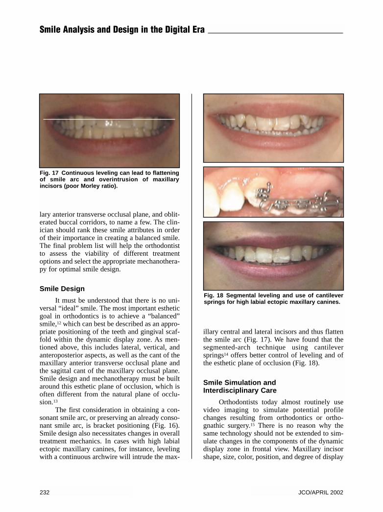
The first consideration in obtaining a con-sonant smile arc, or preserving an already conso-nant smile arc, is bracket positioning (Fig. 16).Smile design also necessitates changes in overalltreatment mechanics. In cases with high labialectopic maxillary canines, for instance, levelingwith a continuous archwire will intrude the max-
illary central and lateral incisors and thus flattenthe smile arc (Fig. 17). We have found that thesegmented-arch technique using cantileversprings14 offers better control of leveling and ofthe esthetic plane of occlusion (Fig. 18).
Smile Simulation andInterdisciplinary Care
Orthodontists today almost routinely usevideo imaging to simulate potential profilechanges resulting from orthodontics or ortho-gnathic surgery.15 There is no reason why thesame technology should not be extended to sim-ulate changes in the components of the dynamicdisplay zone in frontal view. Maxillary incisorshape, size, color, position, and degree of display
Fig. 17 Continuous leveling can lead to flatteningof smile arc and overintrusion of maxillaryincisors (poor Morley ratio).
Fig. 18 Segmental leveling and use of cantileversprings for high labial ectopic maxillary canines.
232 JCO/APRIL 2002
Smile Analysis and Design in the Digital Era
can all be manipulated, and the gingival architec-ture can also be modified. Interdisciplinary careinvolving periodontics, restorative dentistry, andorthodontics can be simulated and presented tothe patient for weighing the risks and benefits ofall treatment options, as the following casesdemonstrate.
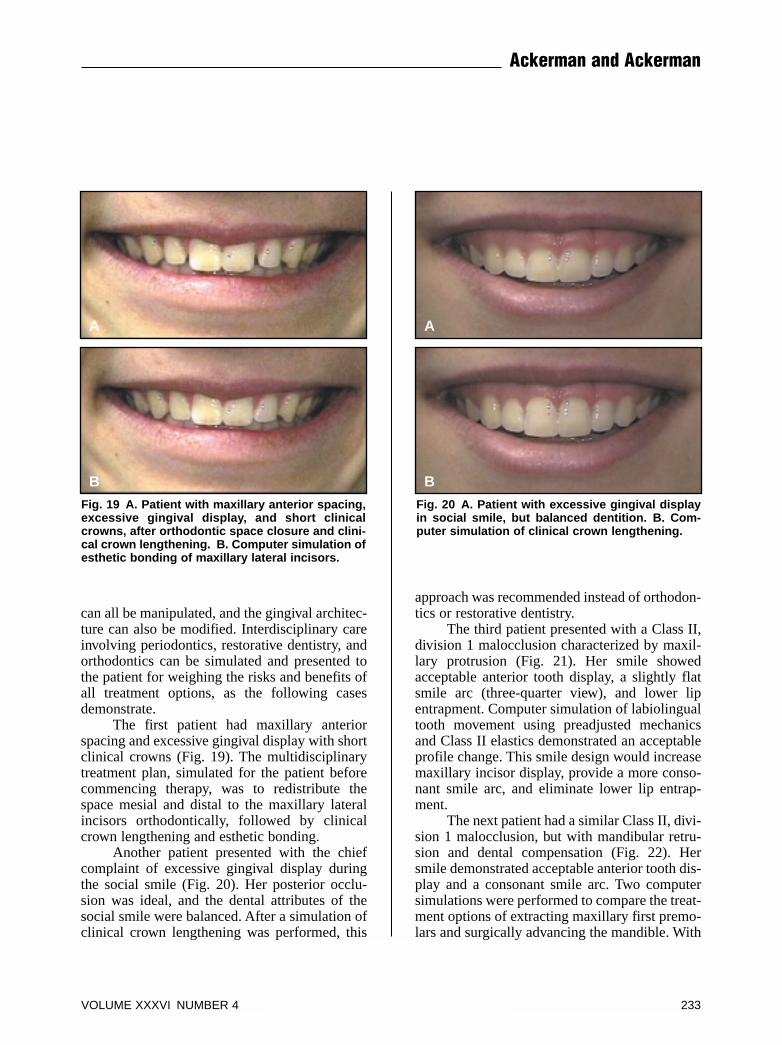
The first patient had maxillary anteriorspacing and excessive gingival display with shortclinical crowns (Fig. 19). The multidisciplinarytreatment plan, simulated for the patient beforecommencing therapy, was to redistribute thespace mesial and distal to the maxillary lateralincisors orthodontically, followed by clinicalcrown lengthening and esthetic bonding.
Another patient presented with the chiefcomplaint of excessive gingival display duringthe social smile (Fig. 20). Her posterior occlu-sion was ideal, and the dental attributes of thesocial smile were balanced. After a simulation ofclinical crown lengthening was performed, this
approach was recommended instead of orthodon-tics or restorative dentistry.
The third patient presented with a Class II,division 1 malocclusion characterized by maxil-lary protrusion (Fig. 21). Her smile showedacceptable anterior tooth display, a slightly flatsmile arc (three-quarter view), and lower lipentrapment. Computer simulation of labiolingualtooth movement using preadjusted mechanicsand Class II elastics demonstrated an acceptableprofile change. This smile design would increasemaxillary incisor display, provide a more conso-nant smile arc, and eliminate lower lip entrap-ment.
The next patient had a similar Class II, divi-sion 1 malocclusion, but with mandibular retru-sion and dental compensation (Fig. 22). Hersmile demonstrated acceptable anterior tooth dis-play and a consonant smile arc. Two computersimulations were performed to compare the treat-ment options of extracting maxillary first premo-lars and surgically advancing the mandible. With
Fig. 19 A. Patient with maxillary anterior spacing,excessive gingival display, and short clinicalcrowns, after orthodontic space closure and clini-cal crown lengthening. B. Computer simulation ofesthetic bonding of maxillary lateral incisors.
B
A
Fig. 20 A. Patient with excessive gingival displayin social smile, but balanced dentition. B. Com-puter simulation of clinical crown lengthening.
B
A
VOLUME XXXVI NUMBER 4 233
Ackerman and Ackerman
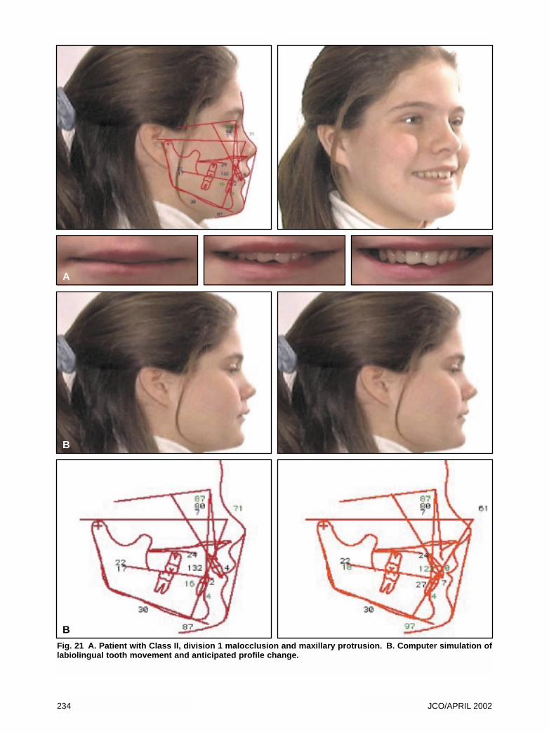
Fig. 21 A. Patient with Class II, division 1 malocclusion and maxillary protrusion. B. Computer simulation oflabiolingual tooth movement and anticipated profile change.
A
B
234 JCO/APRIL 2002
B
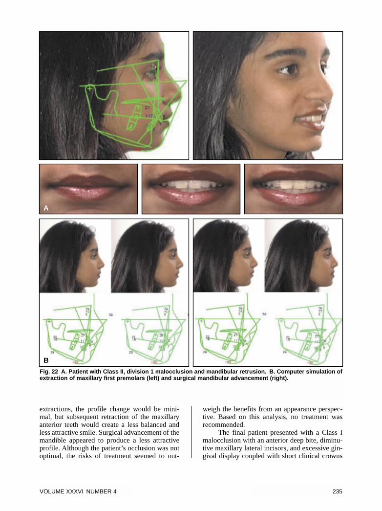
extractions, the profile change would be mini-mal, but subsequent retraction of the maxillaryanterior teeth would create a less balanced andless attractive smile. Surgical advancement of themandible appeared to produce a less attractiveprofile. Although the patient’s occlusion was notoptimal, the risks of treatment seemed to out-
weigh the benefits from an appearance perspec-tive. Based on this analysis, no treatment wasrecommended.
The final patient presented with a Class Imalocclusion with an anterior deep bite, diminu-tive maxillary lateral incisors, and excessive gin-gival display coupled with short clinical crowns
Fig. 22 A. Patient with Class II, division 1 malocclusion and mandibular retrusion. B. Computer simulation ofextraction of maxillary first premolars (left) and surgical mandibular advancement (right).
A
B
VOLUME XXXVI NUMBER 4 235
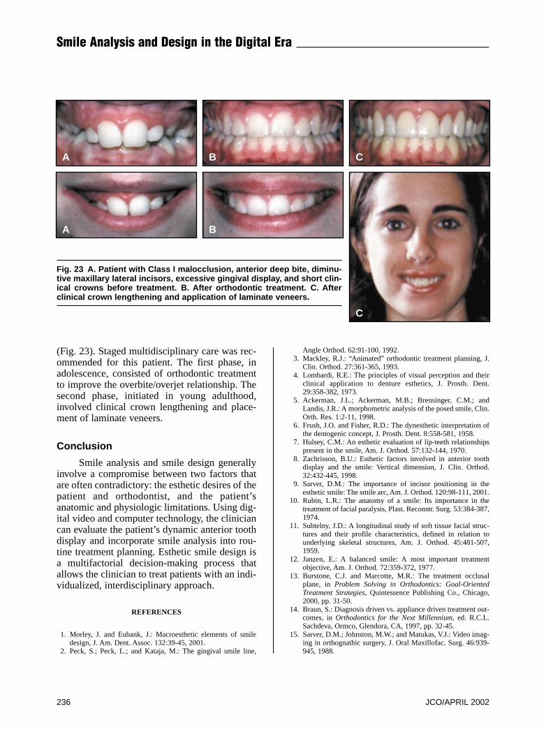
(Fig. 23). Staged multidisciplinary care was rec-ommended for this patient. The first phase, inadolescence, consisted of orthodontic treatmentto improve the overbite/overjet relationship. Thesecond phase, initiated in young adulthood,involved clinical crown lengthening and place-ment of laminate veneers.
Conclusion
Smile analysis and smile design generallyinvolve a compromise between two factors thatare often contradictory: the esthetic desires of thepatient and orthodontist, and the patient’sanatomic and physiologic limitations. Using dig-ital video and computer technology, the cliniciancan evaluate the patient’s dynamic anterior toothdisplay and incorporate smile analysis into rou-tine treatment planning. Esthetic smile design isa multifactorial decision-making process thatallows the clinician to treat patients with an indi-vidualized, interdisciplinary approach.
REFERENCES
1. Morley, J. and Eubank, J.: Macroesthetic elements of smiledesign, J. Am. Dent. Assoc. 132:39-45, 2001.
2. Peck, S.; Peck, L.; and Kataja, M.: The gingival smile line,
Angle Orthod. 62:91-100, 1992.3. Mackley, R.J.: “Animated” orthodontic treatment planning, J.
Clin. Orthod. 27:361-365, 1993.4. Lombardi, R.E.: The principles of visual perception and their
clinical application to denture esthetics, J. Prosth. Dent.29:358-382, 1973.
5. Ackerman, J.L.; Ackerman, M.B.; Brensinger, C.M.; andLandis, J.R.: A morphometric analysis of the posed smile, Clin.Orth. Res. 1:2-11, 1998.
6. Frush, J.O. and Fisher, R.D.: The dynesthetic interpretation ofthe dentogenic concept, J. Prosth. Dent. 8:558-581, 1958.
7. Hulsey, C.M.: An esthetic evaluation of lip-teeth relationshipspresent in the smile, Am. J. Orthod. 57:132-144, 1970.
8. Zachrisson, B.U.: Esthetic factors involved in anterior toothdisplay and the smile: Vertical dimension, J. Clin. Orthod.32:432-445, 1998.
9. Sarver, D.M.: The importance of incisor positioning in theesthetic smile: The smile arc, Am. J. Orthod. 120:98-111, 2001.
10. Rubin, L.R.: The anatomy of a smile: Its importance in thetreatment of facial paralysis, Plast. Reconstr. Surg. 53:384-387,1974.
11. Subtelny, J.D.: A longitudinal study of soft tissue facial struc-tures and their profile characteristics, defined in relation tounderlying skeletal structures, Am. J. Orthod. 45:481-507,1959.
12. Janzen, E.: A balanced smile: A most important treatmentobjective, Am. J. Orthod. 72:359-372, 1977.
13. Burstone, C.J. and Marcotte, M.R.: The treatment occlusalplane, in Problem Solving in Orthodontics: Goal-OrientedTreatment Strategies, Quintessence Publishing Co., Chicago,2000, pp. 31-50.
14. Braun, S.: Diagnosis driven vs. appliance driven treatment out-comes, in Orthodontics for the Next Millennium, ed. R.C.L.Sachdeva, Ormco, Glendora, CA, 1997, pp. 32-45.
15. Sarver, D.M.; Johnston, M.W.; and Matukas, V.J.: Video imag-ing in orthognathic surgery, J. Oral Maxillofac. Surg. 46:939-945, 1988.
Fig. 23 A. Patient with Class I malocclusion, anterior deep bite, diminu-tive maxillary lateral incisors, excessive gingival display, and short clin-ical crowns before treatment. B. After orthodontic treatment. C. Afterclinical crown lengthening and application of laminate veneers.
236 JCO/APRIL 2002
Smile Analysis and Design in the Digital Era
A
A
B
B
C
C


![Design [somente leitura]](https://img.pdfslide.us/doc/110x75/54841d78b47959d80c8b4a8e/design-somente-leitura.jpg)