Embed Size (px)
Citation preview
1 Copyright © 2010, Everlight Americas Inc.. Release Date: 29.Nov. 2016. Issue No:DSE-0011471_Rev.2
www.everlightamericas.com
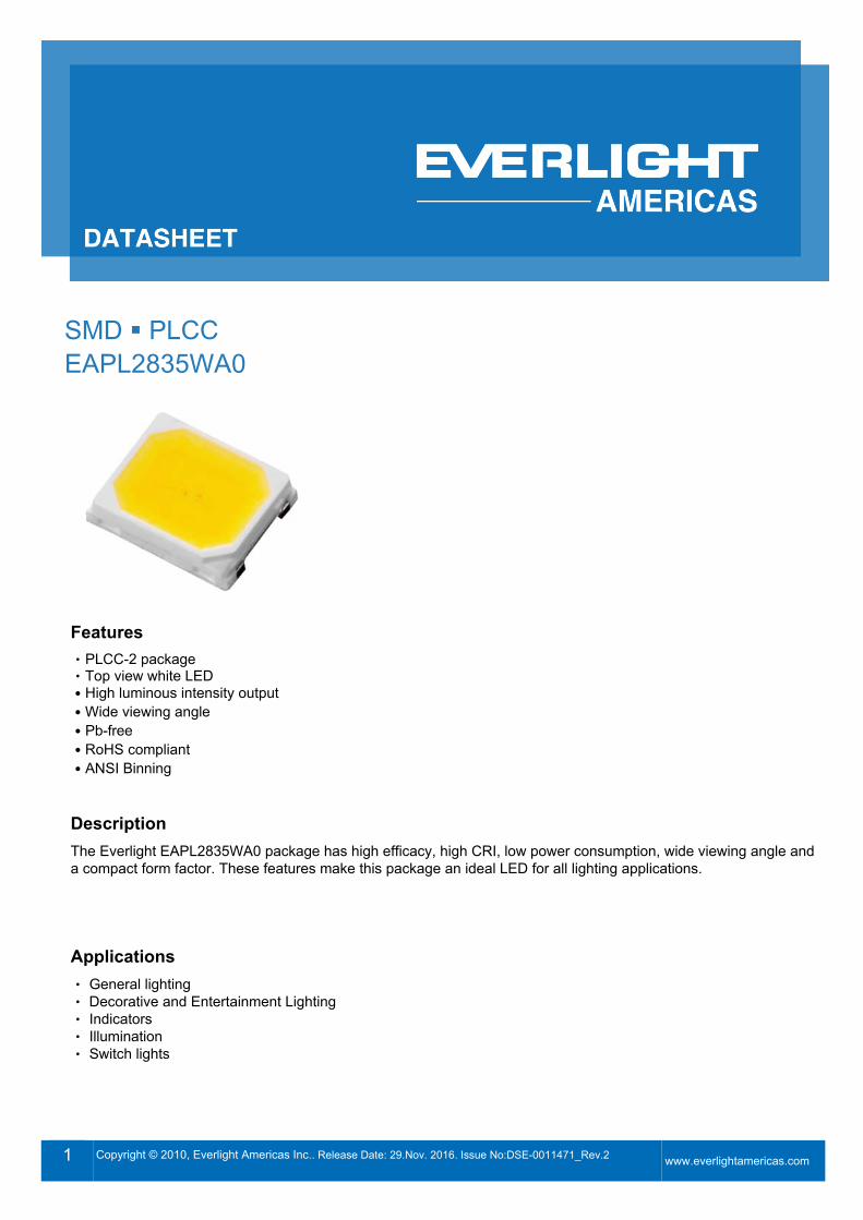
SMD PLCC EAPL2835WA0
Features ‧PLCC-2 package Top view ‧ white LED
˙High luminous intensity output ˙Wide viewing angle ˙Pb-free ˙RoHS compliant ˙ANSI Binning
Description The Everlight EAPL2835WA0 package has high efficacy, high CRI, low power consumption, wide viewing angle and a compact form factor. These features make this package an ideal LED for all lighting applications.
Applications ene‧ ral lighting Decorative and Entertainment Lighting‧ Indicators‧ Illumination‧ Switch lights‧
DATASHEET SMD PLCC EAPL2835WA0
2 Copyright © 2010, Everlight Americas Inc.. Release Date: 29.Nov. 2016. Issue No:DSE-0011471_Rev.2
www.everlightamericas.com
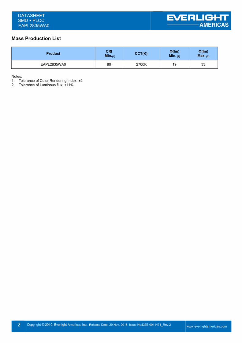
Mass Production List
Product CRI Min.(1) CCT(K) Φ(lm)
Min. (2) Φ(lm)
Max. (2)
EAPL2835WA0 80 2700K 19 33
Notes: 1. Tolerance of Color Rendering Index: ±2 2. Tolerance of Luminous flux: ±11%.
DATASHEET SMD PLCC EAPL2835WA0
3 Copyright © 2010, Everlight Americas Inc.. Release Date: 29.Nov. 2016. Issue No:DSE-0011471_Rev.2
www.everlightamericas.com
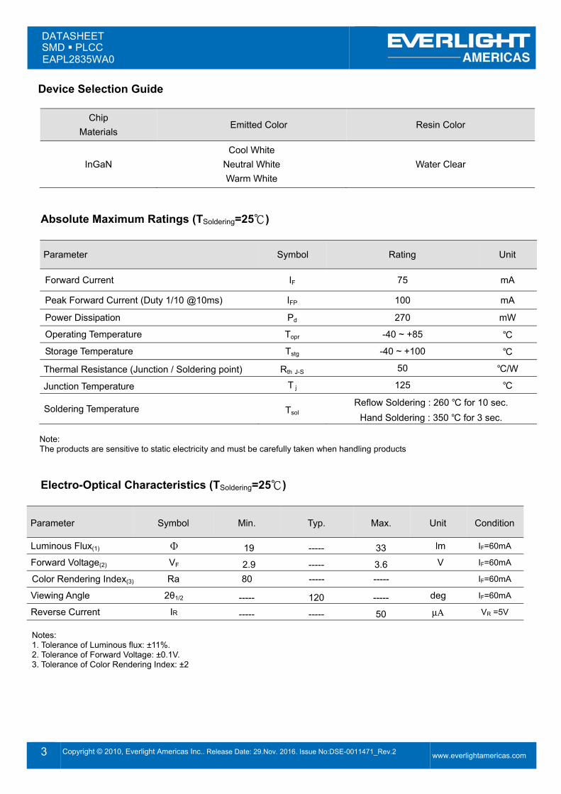
Device Selection Guide
Chip Materials
Emitted Color Resin Color
In aN Cool White Neutral White Warm White
Water Clear
Absolute Maximum Ratings (TSoldering=25℃)
Parameter Symbol Rating Unit
Forward Current IF 75 mA
Peak Forward Current (Duty 1/10 @10ms) IFP 100 mA
Power Dissipation Pd 270 mW
Operating Temperature Topr -40 ~ +85 ℃ Storage Temperature Tstg -40 ~ +100 ℃
Thermal Resistance (Junction / Soldering point) Rth J-S 50 ℃/W
Junction Temperature T j 125 ℃
Soldering Temperature Tsol Reflow Soldering : 260 ℃ for 10 sec. Hand Soldering : 350 ℃ for 3 sec.
Note: The products are sensitive to static electricity and must be carefully taken when handling products
Electro-Optical Characteristics (TSoldering=25℃)
Parameter Symbol Min. Typ. Max. Unit Condition
Luminous Flux(1) Φ 19 ----- 33 lm IF=60mA
Forward Voltage(2) VF 2.9 ----- 3.6 V IF=60mA
Color Rendering Index(3) Ra 80 ----- ----- IF=60mA
Viewing Angle 2θ1/2 ----- 120 ----- deg IF=60mA
Reverse Current IR ----- ----- 50 μΑ VR =5V Notes: 1. Tolerance of Luminous flux: ±11%. 2. Tolerance of Forward Voltage: ±0.1V. 3. Tolerance of Color Rendering Index: ±2
DATASHEET SMD PLCC EAPL2835WA0
4 Copyright © 2010, Everlight Americas Inc.. Release Date: 29.Nov. 2016. Issue No:DSE-0011471_Rev.2
www.everlightamericas.com
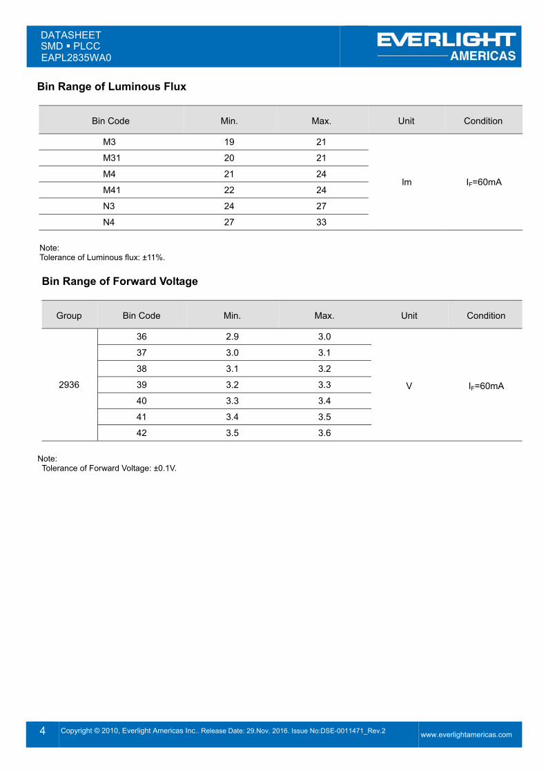
Bin Range of Luminous Flux
Bin Code Min. Max. Unit Condition
M3 19 21
lm IF=60mA
M31 20 21
M4 21 24
M41 22 24
N3 24 27
N4 27 33
Note: Tolerance of Luminous flux: ±11%.
Bin Range of Forward Voltage
roup Bin Code Min. Max. Unit Condition
2936
36 2.9 3.0
V IF=60mA
37 3.0 3.1
38 3.1 3.2
39 3.2 3.3
40 3.3 3.4
41 3.4 3.5
42 3.5 3.6
Note: Tolerance of Forward Voltage: ±0.1V.
DATASHEET SMD PLCC EAPL2835WA0
5 Copyright © 2010, Everlight Americas Inc.. Release Date: 29.Nov. 2016. Issue No:DSE-0011471_Rev.2
www.everlightamericas.com
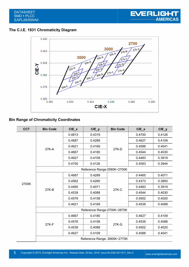
The C.I.E. 1931 Chromaticity Diagram
Bin Range of Chromaticity Coordinates
CCT Bin Code CIE_x CIE_y Bin Code CIE_x CIE_y
2700K
27K-A
0.4813 0.4319
27K-D
0.4700 0.4126
0.4687 0.4289 0.4627 0.4109
0.4621 0.4169 0.4588 0.4041
0.4667 0.4180 0.4544 0.4030
0.4627 0.4109 0.4483 0.3919
0.4700 0.4126 0.4593 0.3944
Reference Range:2580K~2700K
27K-B
0.4687 0.4289
27K-C
0.4465 0.4071
0.4562 0.4260 0.4373 0.3893
0.4465 0.4071 0.4483 0.3919
0.4539 0.4088 0.4544 0.4030
0.4576 0.4158 0.4502 0.4020
0.4621 0.4169 0.4539 0.4088
Reference Range:2700K~2870K
27K-F
0.4667 0.4180
27K-
0.4627 0.4109
0.4576 0.4158 0.4539 0.4088
0.4539 0.4088 0.4502 0.4020
0.4627 0.4109 0.4588 0.4041
Reference Range: 2665K~2770K
DATASHEET SMD PLCC EAPL2835WA0
6 Copyright © 2010, Everlight Americas Inc.. Release Date: 29.Nov. 2016. Issue No:DSE-0011471_Rev.2
www.everlightamericas.com
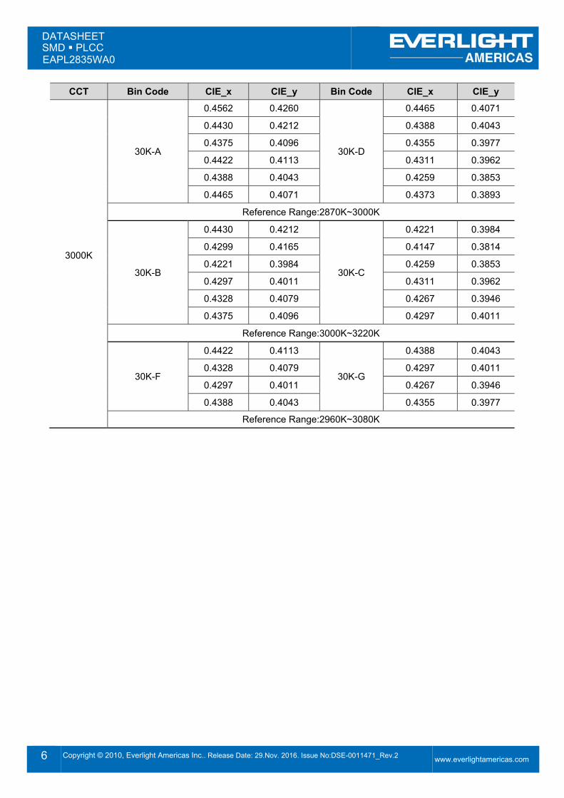
CCT Bin Code CIE_x CIE_y Bin Code CIE_x CIE_y
3000K
30K-A
0.4562 0.4260
30K-D
0.4465 0.4071
0.4430 0.4212 0.4388 0.4043
0.4375 0.4096 0.4355 0.3977
0.4422 0.4113 0.4311 0.3962
0.4388 0.4043 0.4259 0.3853
0.4465 0.4071 0.4373 0.3893
Reference Range:2870K~3000K
30K-B
0.4430 0.4212
30K-C
0.4221 0.3984
0.4299 0.4165 0.4147 0.3814
0.4221 0.3984 0.4259 0.3853
0.4297 0.4011 0.4311 0.3962
0.4328 0.4079 0.4267 0.3946
0.4375 0.4096 0.4297 0.4011
Reference Range:3000K~3220K
30K-F
0.4422 0.4113
30K-
0.4388 0.4043
0.4328 0.4079 0.4297 0.4011
0.4297 0.4011 0.4267 0.3946
0.4388 0.4043 0.4355 0.3977
Reference Range:2960K~3080K
DATASHEET SMD PLCC EAPL2835WA0
7 Copyright © 2010, Everlight Americas Inc.. Release Date: 29.Nov. 2016. Issue No:DSE-0011471_Rev.2
www.everlightamericas.com
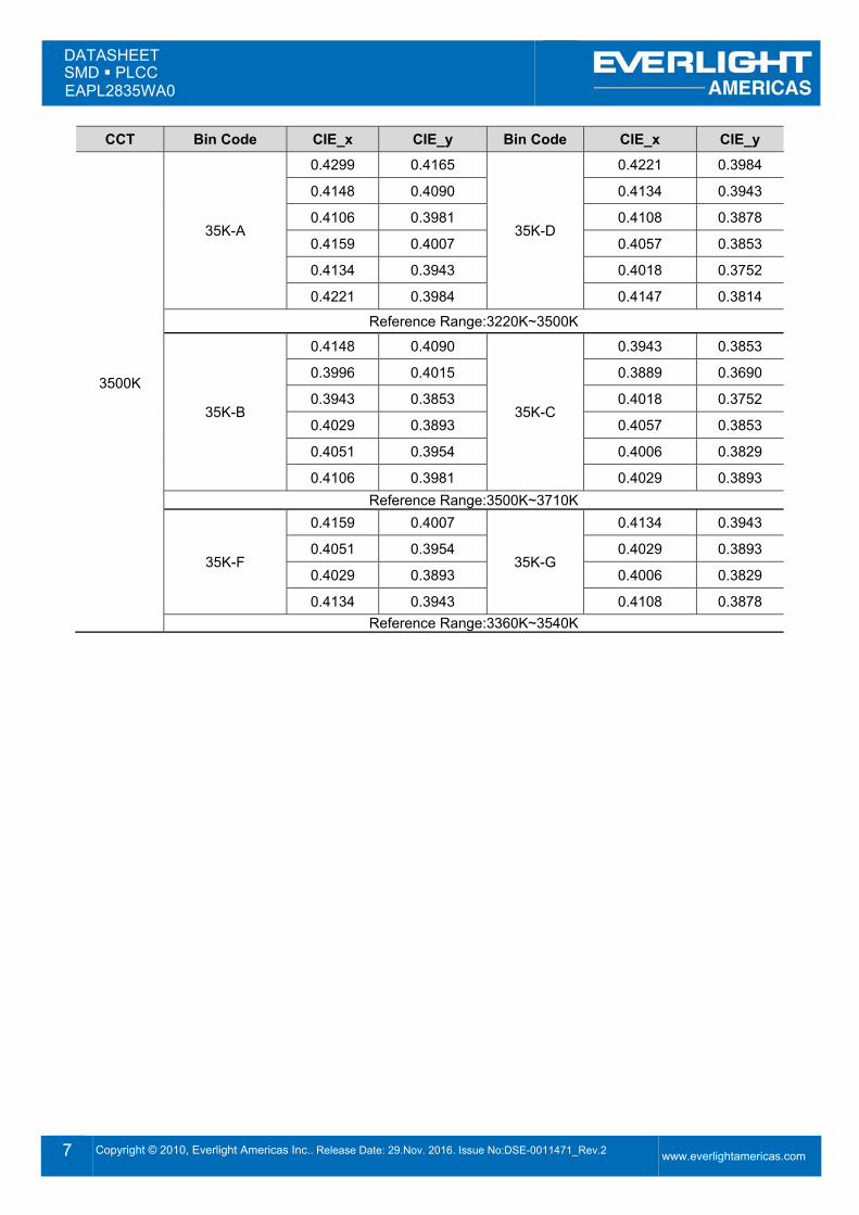
CCT Bin Code CIE_x CIE_y Bin Code CIE_x CIE_y
3500K
35K-A
0.4299 0.4165
35K-D
0.4221 0.3984
0.4148 0.4090 0.4134 0.3943
0.4106 0.3981 0.4108 0.3878
0.4159 0.4007 0.4057 0.3853
0.4134 0.3943 0.4018 0.3752
0.4221 0.3984 0.4147 0.3814
Reference Range:3220K~3500K
35K-B
0.4148 0.4090
35K-C
0.3943 0.3853
0.3996 0.4015 0.3889 0.3690
0.3943 0.3853 0.4018 0.3752
0.4029 0.3893 0.4057 0.3853
0.4051 0.3954 0.4006 0.3829
0.4106 0.3981 0.4029 0.3893 Reference Range:3500K~3710K
35K-F
0.4159 0.4007
35K-
0.4134 0.3943
0.4051 0.3954 0.4029 0.3893
0.4029 0.3893 0.4006 0.3829
0.4134 0.3943 0.4108 0.3878 Reference Range:3360K~3540K
DATASHEET SMD PLCC EAPL2835WA0
8 Copyright © 2010, Everlight Americas Inc.. Release Date: 29.Nov. 2016. Issue No:DSE-0011471_Rev.2
www.everlightamericas.com
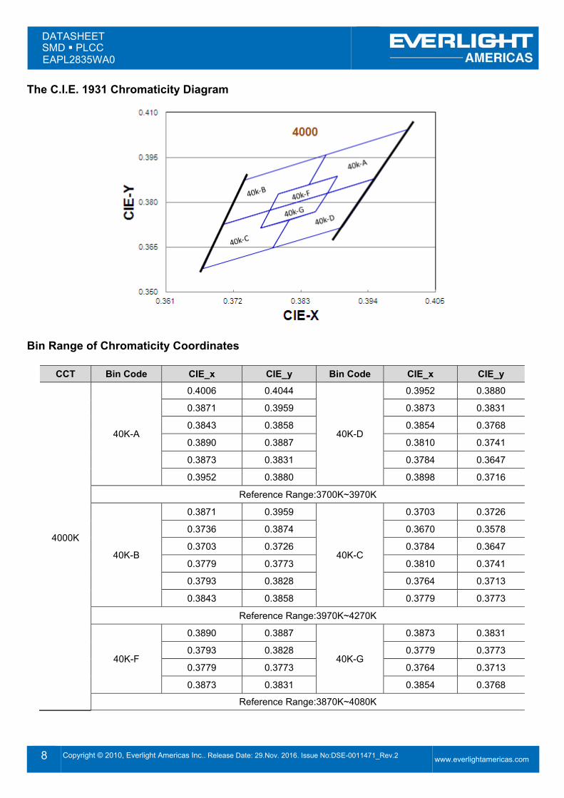
The C.I.E. 1931 Chromaticity Diagram
Bin Range of Chromaticity Coordinates
CCT Bin Code CIE_x CIE_y Bin Code CIE_x CIE_y
4000K
40K-A
0.4006 0.4044
40K-D
0.3952 0.3880
0.3871 0.3959 0.3873 0.3831
0.3843 0.3858 0.3854 0.3768
0.3890 0.3887 0.3810 0.3741
0.3873 0.3831 0.3784 0.3647
0.3952 0.3880 0.3898 0.3716
Reference Range:3700K~3970K
40K-B
0.3871 0.3959
40K-C
0.3703 0.3726
0.3736 0.3874 0.3670 0.3578
0.3703 0.3726 0.3784 0.3647
0.3779 0.3773 0.3810 0.3741
0.3793 0.3828 0.3764 0.3713
0.3843 0.3858 0.3779 0.3773
Reference Range:3970K~4270K
40K-F
0.3890 0.3887
40K-
0.3873 0.3831
0.3793 0.3828 0.3779 0.3773
0.3779 0.3773 0.3764 0.3713
0.3873 0.3831 0.3854 0.3768
Reference Range:3870K~4080K
DATASHEET SMD PLCC EAPL2835WA0
9 Copyright © 2010, Everlight Americas Inc.. Release Date: 29.Nov. 2016. Issue No:DSE-0011471_Rev.2
www.everlightamericas.com
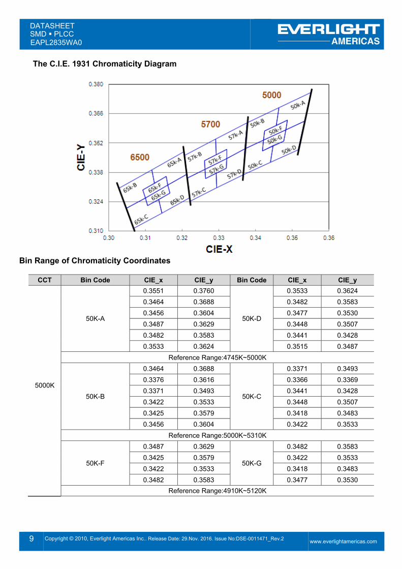
The C.I.E. 1931 Chromaticity Diagram
Bin Range of Chromaticity Coordinates
CCT Bin Code CIE_x CIE_y Bin Code CIE_x CIE_y
5000K
50K-A
0.3551 0.3760
50K-D
0.3533 0.3624 0.3464 0.3688 0.3482 0.3583 0.3456 0.3604 0.3477 0.3530 0.3487 0.3629 0.3448 0.3507 0.3482 0.3583 0.3441 0.3428 0.3533 0.3624 0.3515 0.3487
Reference Range:4745K~5000K
50K-B
0.3464 0.3688
50K-C
0.3371 0.3493 0.3376 0.3616 0.3366 0.3369 0.3371 0.3493 0.3441 0.3428 0.3422 0.3533 0.3448 0.3507 0.3425 0.3579 0.3418 0.3483 0.3456 0.3604 0.3422 0.3533
Reference Range:5000K~5310K
50K-F
0.3487 0.3629
50K-
0.3482 0.3583 0.3425 0.3579 0.3422 0.3533 0.3422 0.3533 0.3418 0.3483 0.3482 0.3583 0.3477 0.3530
Reference Range:4910K~5120K
DATASHEET SMD PLCC EAPL2835WA0
10 Copyright © 2010, Everlight Americas Inc.. Release Date: 29.Nov. 2016. Issue No:DSE-0011471_Rev.2
www.everlightamericas.com
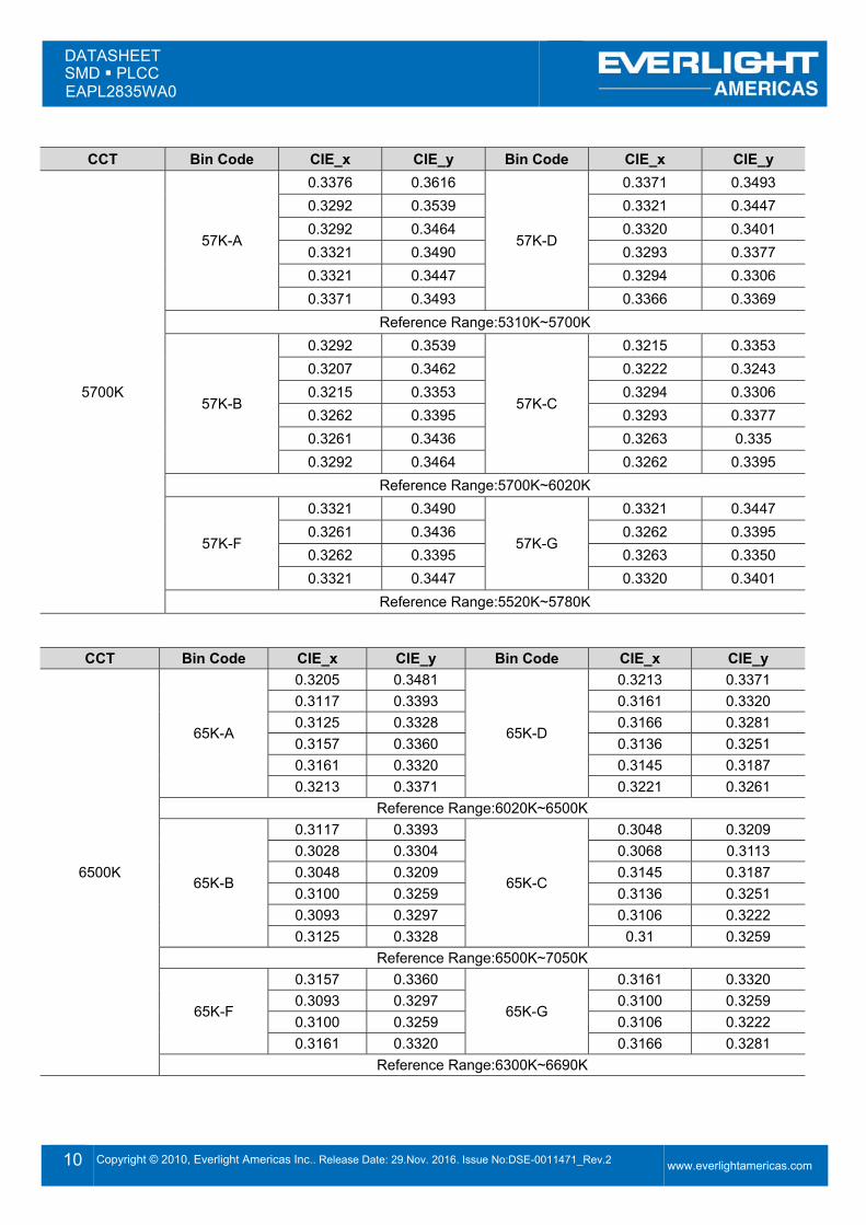
CCT Bin Code CIE_x CIE_y Bin Code CIE_x CIE_y
5700K
57K-A
0.3376 0.3616
57K-D
0.3371 0.3493 0.3292 0.3539 0.3321 0.3447 0.3292 0.3464 0.3320 0.3401 0.3321 0.3490 0.3293 0.3377 0.3321 0.3447 0.3294 0.3306 0.3371 0.3493 0.3366 0.3369
Reference Range:5310K~5700K
57K-B
0.3292 0.3539
57K-C
0.3215 0.3353 0.3207 0.3462 0.3222 0.3243 0.3215 0.3353 0.3294 0.3306 0.3262 0.3395 0.3293 0.3377 0.3261 0.3436 0.3263 0.335 0.3292 0.3464 0.3262 0.3395
Reference Range:5700K~6020K
57K-F
0.3321 0.3490
57K-
0.3321 0.3447 0.3261 0.3436 0.3262 0.3395 0.3262 0.3395 0.3263 0.3350 0.3321 0.3447 0.3320 0.3401
Reference Range:5520K~5780K
CCT Bin Code CIE_x CIE_y Bin Code CIE_x CIE_y
6500K
65K-A
0.3205 0.3481
65K-D
0.3213 0.3371 0.3117 0.3393 0.3161 0.3320 0.3125 0.3328 0.3166 0.3281 0.3157 0.3360 0.3136 0.3251 0.3161 0.3320 0.3145 0.3187 0.3213 0.3371 0.3221 0.3261
Reference Range:6020K~6500K
65K-B
0.3117 0.3393
65K-C
0.3048 0.3209 0.3028 0.3304 0.3068 0.3113 0.3048 0.3209 0.3145 0.3187 0.3100 0.3259 0.3136 0.3251 0.3093 0.3297 0.3106 0.3222 0.3125 0.3328 0.31 0.3259
Reference Range:6500K~7050K
65K-F
0.3157 0.3360
65K-
0.3161 0.3320 0.3093 0.3297 0.3100 0.3259 0.3100 0.3259 0.3106 0.3222 0.3161 0.3320 0.3166 0.3281
Reference Range:6300K~6690K
DATASHEET SMD PLCC EAPL2835WA0
11 Copyright © 2010, Everlight Americas Inc.. Release Date: 29.Nov. 2016. Issue No:DSE-0011471_Rev.2
www.everlightamericas.com
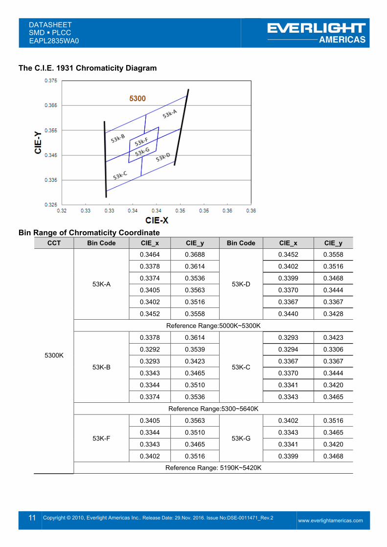
The C.I.E. 1931 Chromaticity Diagram
Bin Range of Chromaticity Coordinate
CCT Bin Code CIE_x CIE_y Bin Code CIE_x CIE_y
5300K
53K-A
0.3464 0.3688
53K-D
0.3452 0.3558
0.3378 0.3614 0.3402 0.3516
0.3374 0.3536 0.3399 0.3468
0.3405 0.3563 0.3370 0.3444
0.3402 0.3516 0.3367 0.3367
0.3452 0.3558 0.3440 0.3428
Reference Range:5000K~5300K
53K-B
0.3378 0.3614
53K-C
0.3293 0.3423
0.3292 0.3539 0.3294 0.3306
0.3293 0.3423 0.3367 0.3367
0.3343 0.3465 0.3370 0.3444
0.3344 0.3510 0.3341 0.3420
0.3374 0.3536 0.3343 0.3465
Reference Range:5300~5640K
53K-F
0.3405 0.3563
53K-
0.3402 0.3516
0.3344 0.3510 0.3343 0.3465
0.3343 0.3465 0.3341 0.3420
0.3402 0.3516 0.3399 0.3468
Reference Range: 5190K~5420K
DATASHEET SMD PLCC EAPL2835WA0
12 Copyright © 2010, Everlight Americas Inc.. Release Date: 29.Nov. 2016. Issue No:DSE-0011471_Rev.2
www.everlightamericas.com
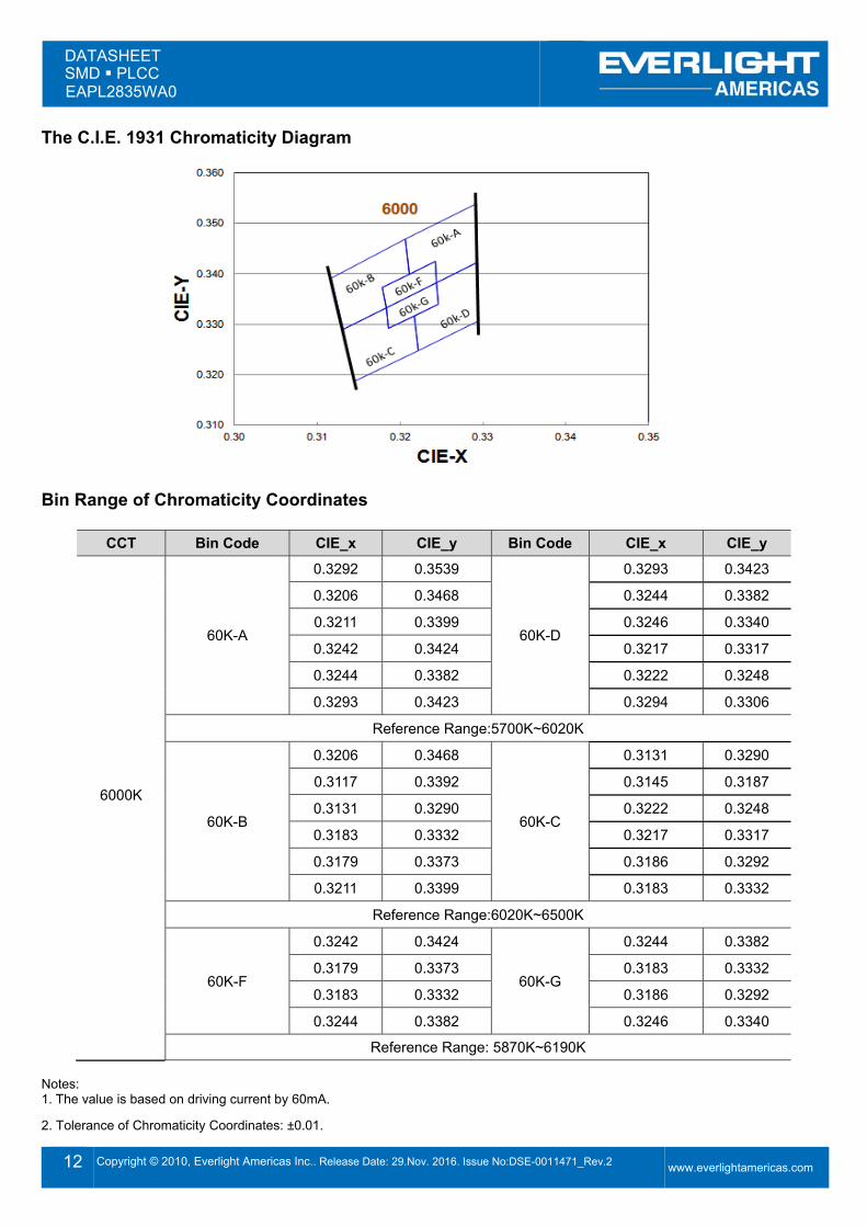
The C.I.E. 1931 Chromaticity Diagram
Bin Range of Chromaticity Coordinates
CCT Bin Code CIE_x CIE_y Bin Code CIE_x CIE_y
6000K
60K-A
0.3292 0.3539
60K-D
0.3293 0.3423
0.3206 0.3468 0.3244 0.3382
0.3211 0.3399 0.3246 0.3340
0.3242 0.3424 0.3217 0.3317
0.3244 0.3382 0.3222 0.3248
0.3293 0.3423 0.3294 0.3306
Reference Range:5700K~6020K
60K-B
0.3206 0.3468
60K-C
0.3131 0.3290
0.3117 0.3392 0.3145 0.3187
0.3131 0.3290 0.3222 0.3248
0.3183 0.3332 0.3217 0.3317
0.3179 0.3373 0.3186 0.3292
0.3211 0.3399 0.3183 0.3332
Reference Range:6020K~6500K
60K-F
0.3242 0.3424
60K-
0.3244 0.3382
0.3179 0.3373 0.3183 0.3332
0.3183 0.3332 0.3186 0.3292
0.3244 0.3382 0.3246 0.3340
Reference Range: 5870K~6190K Notes: 1. The value is based on driving current by 60mA.
2. Tolerance of Chromaticity Coordinates: ±0.01.
DATASHEET SMD PLCC EAPL2835WA0
13 Copyright © 2010, Everlight Americas Inc.. Release Date: 29.Nov. 2016. Issue No:DSE-0011471_Rev.2
www.everlightamericas.com
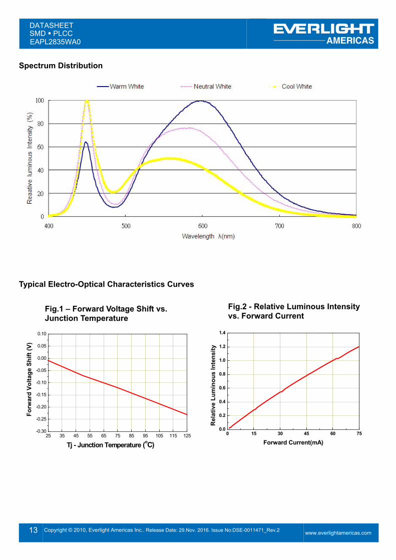
Spectrum Distribution
Typical Electro-Optical Characteristics Curves
25 35 45 55 65 75 85 95 105 115 125-0.30
-0.25
-0.20
-0.15
-0.10
-0.05
0.00
0.05
0.10
For
war
d Vo
ltage
Shi
ft (V
)
Tj - Junction Temperature (oC)
0 15 30 45 60 750.0
0.2
0.4
0.6
0.8
1.0
1.2
1.4
Rel
ativ
e Lu
min
ous
Inte
nsity
Forward Current(mA)
Fig.1 – Forward Voltage Shift vs. Junction Temperature
Fig.2 - Relative Luminous Intensity vs. Forward Current
DATASHEET SMD PLCC EAPL2835WA0
14 Copyright © 2010, Everlight Americas Inc.. Release Date: 29.Nov. 2016. Issue No:DSE-0011471_Rev.2
www.everlightamericas.com
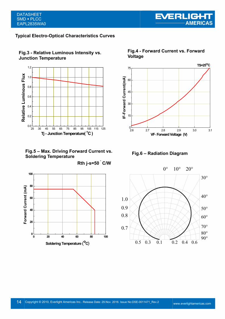
Typical Electro-Optical Characteristics Curves
25 35 45 55 65 75 85 95 105 115 1250.0
0.2
0.4
0.6
0.8
1.0
1.2
Tj - Junction Temperature( oC )
Rel
ativ
e Lu
min
ous
Flux
2.6 2.7 2.8 2.9 3.0 3.10
15
30
45
60
75TS=25oC
IF-F
orw
ard
Cur
rent
(mA
)
VF- Forward Voltage (V)
0 20 40 60 80 1000
20
40
60
80
100
Forw
ard
Cur
rent
(mA
)
Soldering Temperature (oC)
0.7
0.80.91.0
0.10.30.5 0.2 0.4
80°90°
0.6
50°
60°
70°
40°
20°0° 10°30°
Fig.3 - Relative Luminous Intensity vs. Junction Temperature
Fig.4 - Forward Current vs. Forward Voltage
Fig.5 – Max. Driving Forward Current vs. Soldering Temperature Rth j-s=50。C/W
Fig.6 – Radiation Diagram
DATASHEET SMD PLCC EAPL2835WA0
15 Copyright © 2010, Everlight Americas Inc.. Release Date: 29.Nov. 2016. Issue No:DSE-0011471_Rev.2
www.everlightamericas.com
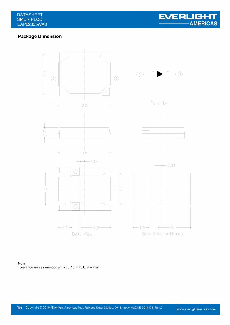
Package Dimension
Note: Tolerance unless mentioned is ±0.15 mm; Unit = mm
DATASHEET SMD PLCC EAPL2835WA0
16 Copyright © 2010, Everlight Americas Inc.. Release Date: 29.Nov. 2016. Issue No:DSE-0011471_Rev.2
www.everlightamericas.com
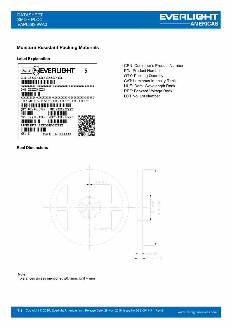
Moisture Resistant Packing Materials Label Explanation
‧CPN: Customer’s Product Number ‧P/N: Product Number ‧QTY: Packing Quantity ‧CAT: Luminous Intensity Rank ‧HUE: Dom. Wavelength Rank ‧REF: Forward Voltage Rank ‧LOT No: Lot Number
Reel Dimensions
Note: Tolerances unless mentioned ±0.1mm. Unit = mm
DATASHEET SMD PLCC EAPL2835WA0
17 Copyright © 2010, Everlight Americas Inc.. Release Date: 29.Nov. 2016. Issue No:DSE-0011471_Rev.2
www.everlightamericas.com
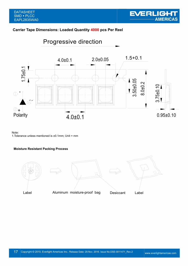
Carrier Tape Dimensions: Loaded Quantity 4000 pcs Per Reel
Progressive direction
1.5+0.1
Note: 1.Tolerance unless mentioned is ±0.1mm; Unit = mm
Moisture Resistant Packing Process
Label Aluminum moisture-proof bag Desiccant Label
DATASHEET SMD PLCC EAPL2835WA0
18 Copyright © 2010, Everlight Americas Inc.. Release Date: 29.Nov. 2016. Issue No:DSE-0011471_Rev.2
www.everlightamericas.com
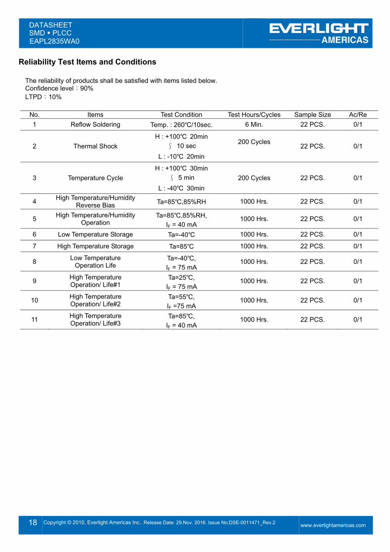
Reliability Test Items and Conditions The reliability of products shall be satisfied with items listed below. Confidence level:90% LTPD:10%
No. Items Test Condition Test Hours/Cycles Sample Size Ac/Re 1 Reflow Soldering Temp. : 260℃/10sec. 6 Min. 22 PCS. 0/1
2 Thermal Shock H : +100℃ 20min
∫ 10 sec L : -10℃ 20min
200 Cycles 22 PCS. 0/1
3 Temperature Cycle H : +100℃ 30min
∫ 5 min L : -40℃ 30min
200 Cycles 22 PCS. 0/1
4 High Temperature/Humidity Reverse Bias Ta=85℃,85%RH 1000 Hrs. 22 PCS. 0/1
5 High Temperature/Humidity Operation
Ta=85℃,85%RH, IF = 40 mA
1000 Hrs. 22 PCS. 0/1
6 Low Temperature Storage Ta=-40℃ 1000 Hrs. 22 PCS. 0/1
7 High Temperature Storage Ta=85℃ 1000 Hrs. 22 PCS. 0/1
8 Low Temperature Operation Life
Ta=-40℃, IF = 75 mA
1000 Hrs. 22 PCS. 0/1
9 High Temperature Operation/ Life#1
Ta=25℃, IF = 75 mA
1000 Hrs. 22 PCS. 0/1
10 High Temperature Operation/ Life#2
Ta=55℃, IF =75 mA
1000 Hrs. 22 PCS. 0/1
11 High Temperature Operation/ Life#3
Ta=85℃, IF = 40 mA
1000 Hrs. 22 PCS. 0/1
DATASHEET SMD PLCC EAPL2835WA0
19 Copyright © 2010, Everlight Americas Inc.. Release Date: 29.Nov. 2016. Issue No:DSE-0011471_Rev.2
www.everlightamericas.com
Precautions for Use
1. Over-current-proof Customer must apply resistors for protection; otherwise slight voltage shift will cause big current change (Burn out will happen).
2. Storage 2.1 Do not open moisture proof bag before the products are ready to use. 2.2 Before opening the package: The LEDs should be kept at 30℃ or less and 90%RH or less. 2.3 After opening the package: The LED's floor life is 168 Hrs under 30℃ or less and 60% RH or less. If unused LEDs remain, it should be stored in moisture proof packages.
2.4 If the moisture absorbent material (silica gel) has faded away or the LEDs have exceeded the storage time, baking treatment should be performed using the following conditions. Baking treatment: 60±5℃ for 24 hours.
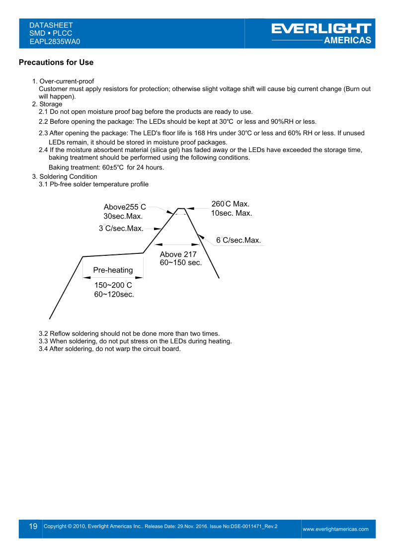
3. Soldering Condition 3.1 Pb-free solder temperature profile
260 Max.10sec. Max.
6 C/sec.Max.
Above255 C30sec.Max.
C
Above 21760~150 sec.
3 C/sec.Max.
Pre-heating
150~200 C60~120sec.
3.2 Reflow soldering should not be done more than two times. 3.3 When soldering, do not put stress on the LEDs during heating. 3.4 After soldering, do not warp the circuit board.
DATASHEET SMD PLCC EAPL2835WA0
20 Copyright © 2010, Everlight Americas Inc.. Release Date: 29.Nov. 2016. Issue No:DSE-0011471_Rev.2
www.everlightamericas.com
4. Soldering Iron Each terminal is to go to the tip of soldering iron temperature less than 350℃ for 3 seconds within once in less than the soldering iron capacity 25W. Leave two seconds and more intervals, and do soldering of each terminal. Be careful because the damage of the product is often started at the time of the hand solder.
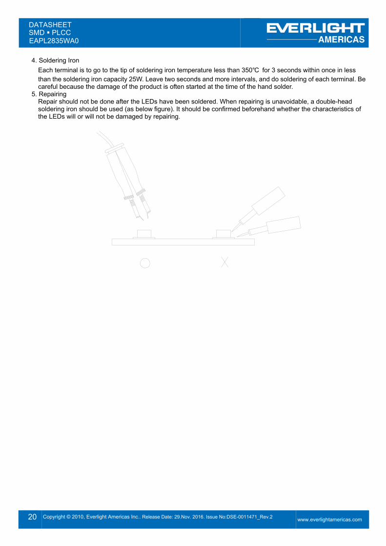
5. Repairing Repair should not be done after the LEDs have been soldered. When repairing is unavoidable, a double-head soldering iron should be used (as below figure). It should be confirmed beforehand whether the characteristics of the LEDs will or will not be damaged by repairing.