Embed Size (px)
Citation preview
1 Copyright © 2010, Everlight All Rights Reserved. Release Date : 19.Oct.2011. Issue No: V2 Issue No:
www.everlight.com
SMD Low Power LED
45-21/XK2C-BXXXXXXXXX/2T
Features ‧PLCC-2 package
Top view ‧ white LED ․High luminous intensity output ․Wide viewing angle ․Pb-free ․RoHS compliant
Description The Everlight 45-21 package has high efficacy, high CRI, low power consumption, wide viewing angle and a compact form factor. These features make this package an ideal LED for all lighting applications.
Applications ‧ General lighting Decorative and Entertainment Lighting‧ Indicators‧ Illumination‧ Switch lights‧
DATASHEET SMD Low Power LED 45-21/XK2C-BXXXXXXXXXX/2T
2 Copyright © 2010, Everlight All Rights Reserved. Release Date : 19.Oct.2011. Issue No: V2 Issue No:
www.everlight.com
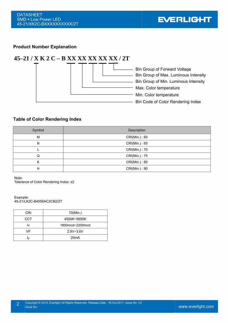
Product Number Explanation 45–21 / X K 2 C – B XX XX XX XX XX / 2T
Table of Color Rendering Index
Symbol Description
M CRI(Min.) : 60
N CRI(Min.) : 65
L CRI(Min.) : 70
Q CRI(Min.) : 75
K CRI(Min.) : 80
H CRI(Min.) : 90 Note: Tolerance of Color Rendering Index: ±2
Example: 45-21/LK2C-B4556AC2CB2/2T
CRI 70(Min.)
CCT 4500K~5650K
Iv 1800mcd~2200mcd
VF 2.9V~3.6V
IF 20mA
Bin Group of Forward VoltageBin Group of Max. Luminous Intensity Bin Group of Min. Luminous Intensity Max. Color temperature Min. Color temperature Bin Code of Color Rendering Index
DATASHEET SMD Low Power LED 45-21/XK2C-BXXXXXXXXXX/2T
3 Copyright © 2010, Everlight All Rights Reserved. Release Date : 19.Oct.2011. Issue No: V2 Issue No:
www.everlight.com
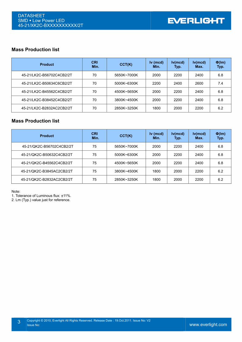
Mass Production list
Product CRI Min. CCT(K) Iv (mcd)
Min. Iv(mcd)
Typ. Iv(mcd)
Max. Φ(lm) Typ.
45-21/LK2C-B56702C4CB2/2T 70 5650K~7000K 2000 2200 2400 6.8
45-21/LK2C-B50634C6CB2/2T 70 5000K~6300K 2200 2400 2600 7.4
45-21/LK2C-B45562C4CB2/2T 70 4500K~5650K 2000 2200 2400 6.8
45-21/LK2C-B38452C4CB2/2T 70 3800K~4500K 2000 2200 2400 6.8
45-21/LK2C-B2832AC2CB2/2T 70 2850K~3250K 1800 2000 2200 6.2
Mass Production list
Product CRI Min. CCT(K) Iv (mcd)
Min. Iv(mcd)
Typ. Iv(mcd)
Max. Φ(lm) Typ.
45-21/QK2C-B56702C4CB2/2T 75 5650K~7000K 2000 2200 2400 6.8
45-21/QK2C-B50632C4CB2/2T 75 5000K~6300K 2000 2200 2400 6.8
45-21/QK2C-B45562C4CB2/2T 75 4500K~5650K 2000 2200 2400 6.8
45-21/QK2C-B3845AC2CB2/2T 75 3800K~4500K 1800 2000 2200 6.2
45-21/QK2C-B2832AC2CB2/2T 75 2850K~3250K 1800 2000 2200 6.2
Note: 1. Tolerance of Luminous flux: ±11%. 2. Lm (Typ.) value just for reference.
DATASHEET SMD Low Power LED 45-21/XK2C-BXXXXXXXXXX/2T
4 Copyright © 2010, Everlight All Rights Reserved. Release Date : 19.Oct.2011. Issue No: V2 Issue No:
www.everlight.com
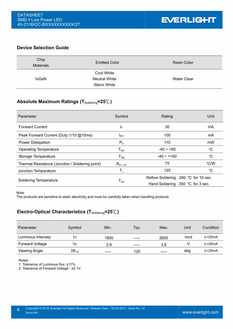
Device Selection Guide
Chip Materials
Emitted Color Resin Color
InGaN Cool White
Neutral White Warm White
Water Clear
Absolute Maximum Ratings (TSoldering=25℃)
Parameter Symbol Rating Unit
Forward Current IF 30 mA
Peak Forward Current (Duty 1/10 @10ms) IFP 100 mA
Power Dissipation Pd 110 mW
Operating Temperature Topr -40 ~ +85 ℃ Storage Temperature Tstg -40 ~ +100 ℃
Thermal Resistance (Junction / Soldering point) Rth J-S 75 ℃/W
Junction Temperature T j 125 ℃
Soldering Temperature Tsol Reflow Soldering : 260 ℃ for 10 sec.
Hand Soldering : 350 ℃ for 3 sec. Note: The products are sensitive to static electricity and must be carefully taken when handling products
Electro-Optical Characteristics (TSoldering=25℃)
Parameter Symbol Min. Typ. Max. Unit Condition
Luminous intensity Iv 1800 ----- 2600 mcd IF=20mA
Forward Voltage VF 2.9 ----- 3.6 V IF=20mA
Viewing Angle 2θ1/2 ----- 120 ----- deg IF=20mA Notes: 1. Tolerance of Luminous flux: ±11%. 2. Tolerance of Forward Voltage : ±0.1V.
DATASHEET SMD Low Power LED 45-21/XK2C-BXXXXXXXXXX/2T
5 Copyright © 2010, Everlight All Rights Reserved. Release Date : 19.Oct.2011. Issue No: V2 Issue No:
www.everlight.com
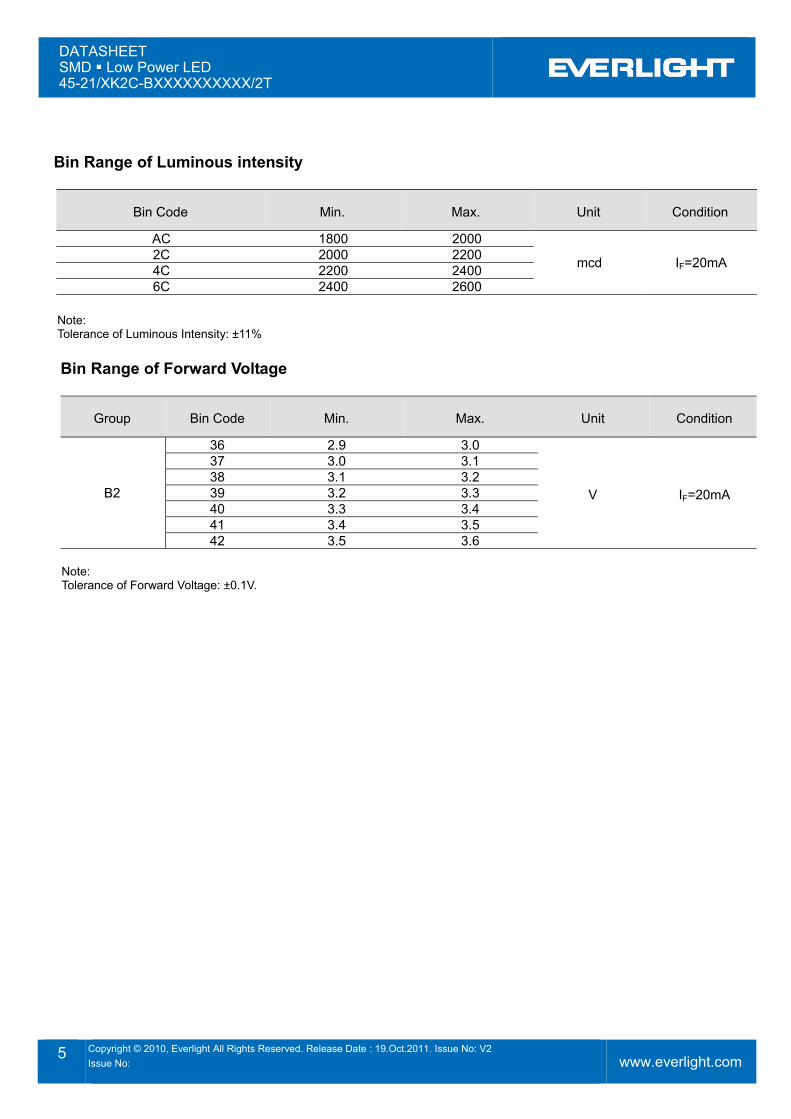
Bin Range of Luminous intensity
Bin Code Min. Max. Unit Condition
AC 1800 2000
mcd IF=20mA 2C 2000 2200 4C 2200 2400 6C 2400 2600
Note: Tolerance of Luminous Intensity: ±11%
Bin Range of Forward Voltage
Group Bin Code Min. Max. Unit Condition
B2
36 2.9 3.0
V IF=20mA
37 3.0 3.1 38 3.1 3.2 39 3.2 3.3 40 3.3 3.4 41 3.4 3.5 42 3.5 3.6
Note: Tolerance of Forward Voltage: ±0.1V.
DATASHEET SMD Low Power LED 45-21/XK2C-BXXXXXXXXXX/2T
6 Copyright © 2010, Everlight All Rights Reserved. Release Date : 19.Oct.2011. Issue No: V2 Issue No:
www.everlight.com
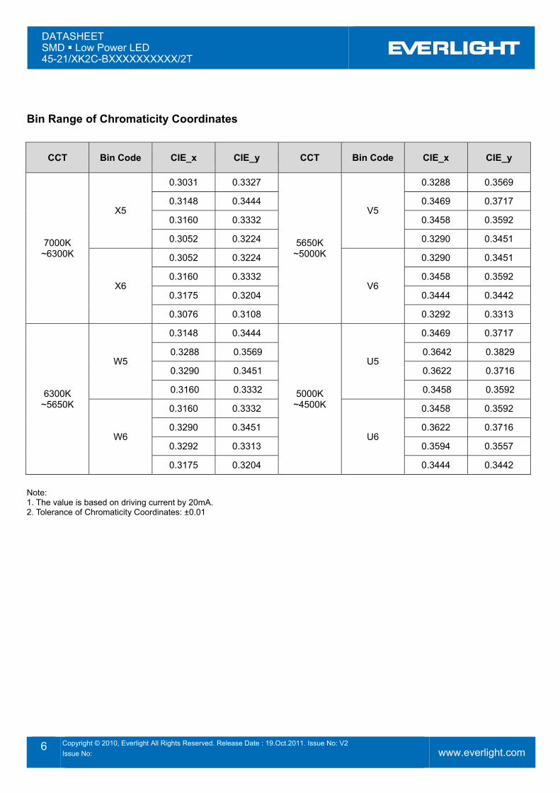
Bin Range of Chromaticity Coordinates
CCT Bin Code CIE_x CIE_y CCT Bin Code CIE_x CIE_y
7000K ~6300K
X5
0.3031 0.3327
5650K ~5000K
V5
0.3288 0.3569
0.3148 0.3444 0.3469 0.3717
0.3160 0.3332 0.3458 0.3592
0.3052 0.3224 0.3290 0.3451
X6
0.3052 0.3224
V6
0.3290 0.3451
0.3160 0.3332 0.3458 0.3592
0.3175 0.3204 0.3444 0.3442
0.3076 0.3108 0.3292 0.3313
6300K ~5650K
W5
0.3148 0.3444
5000K ~4500K
U5
0.3469 0.3717
0.3288 0.3569 0.3642 0.3829
0.3290 0.3451 0.3622 0.3716
0.3160 0.3332 0.3458 0.3592
W6
0.3160 0.3332
U6
0.3458 0.3592
0.3290 0.3451 0.3622 0.3716
0.3292 0.3313 0.3594 0.3557
0.3175 0.3204 0.3444 0.3442
Note: 1. The value is based on driving current by 20mA. 2. Tolerance of Chromaticity Coordinates: ±0.01
DATASHEET SMD Low Power LED 45-21/XK2C-BXXXXXXXXXX/2T
7 Copyright © 2010, Everlight All Rights Reserved. Release Date : 19.Oct.2011. Issue No: V2 Issue No:
www.everlight.com
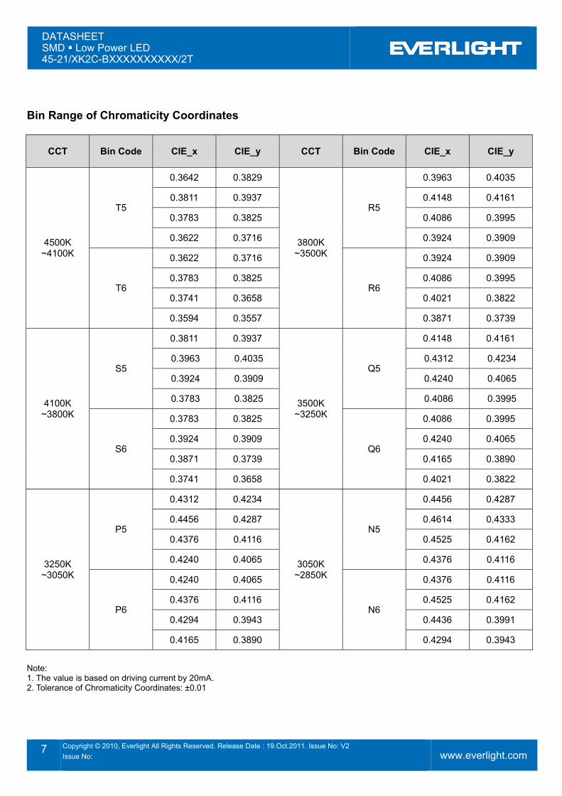
Bin Range of Chromaticity Coordinates
CCT Bin Code CIE_x CIE_y CCT Bin Code CIE_x CIE_y
4500K ~4100K
T5
0.3642 0.3829
3800K ~3500K
R5
0.3963 0.4035
0.3811 0.3937 0.4148 0.4161
0.3783 0.3825 0.4086 0.3995
0.3622 0.3716 0.3924 0.3909
T6
0.3622 0.3716
R6
0.3924 0.3909
0.3783 0.3825 0.4086 0.3995
0.3741 0.3658 0.4021 0.3822
0.3594 0.3557 0.3871 0.3739
4100K ~3800K
S5
0.3811 0.3937
3500K ~3250K
Q5
0.4148 0.4161
0.3963 0.4035 0.4312 0.4234
0.3924 0.3909 0.4240 0.4065
0.3783 0.3825 0.4086 0.3995
S6
0.3783 0.3825
Q6
0.4086 0.3995
0.3924 0.3909 0.4240 0.4065
0.3871 0.3739 0.4165 0.3890
0.3741 0.3658 0.4021 0.3822
3250K ~3050K
P5
0.4312 0.4234
3050K ~2850K
N5
0.4456 0.4287
0.4456 0.4287 0.4614 0.4333
0.4376 0.4116 0.4525 0.4162
0.4240 0.4065 0.4376 0.4116
P6
0.4240 0.4065
N6
0.4376 0.4116
0.4376 0.4116 0.4525 0.4162
0.4294 0.3943 0.4436 0.3991
0.4165 0.3890 0.4294 0.3943
Note: 1. The value is based on driving current by 20mA. 2. Tolerance of Chromaticity Coordinates: ±0.01
DATASHEET SMD Low Power LED 45-21/XK2C-BXXXXXXXXXX/2T
8 Copyright © 2010, Everlight All Rights Reserved. Release Date : 19.Oct.2011. Issue No: V2 Issue No:
www.everlight.com
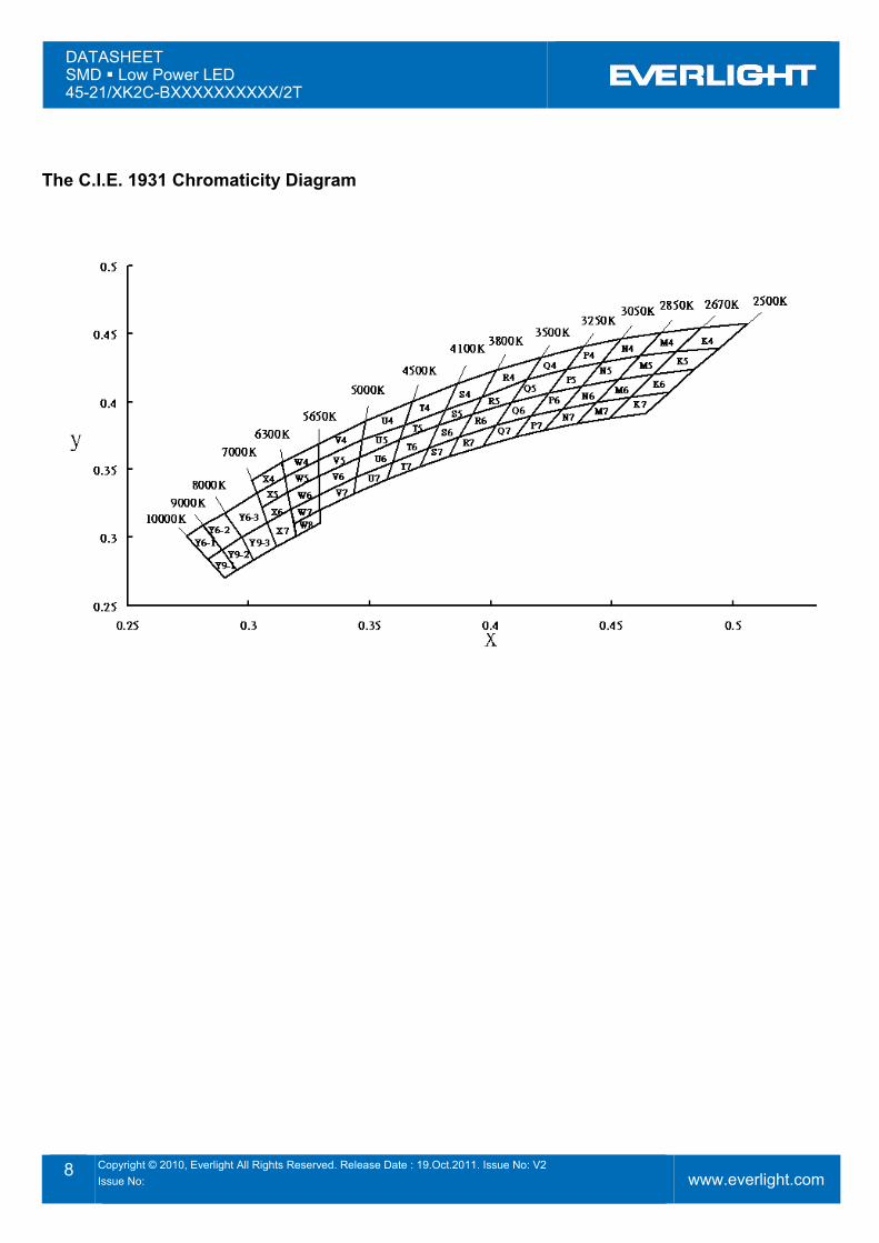
The C.I.E. 1931 Chromaticity Diagram
DATASHEET SMD Low Power LED 45-21/XK2C-BXXXXXXXXXX/2T
9 Copyright © 2010, Everlight All Rights Reserved. Release Date : 19.Oct.2011. Issue No: V2 Issue No:
www.everlight.com
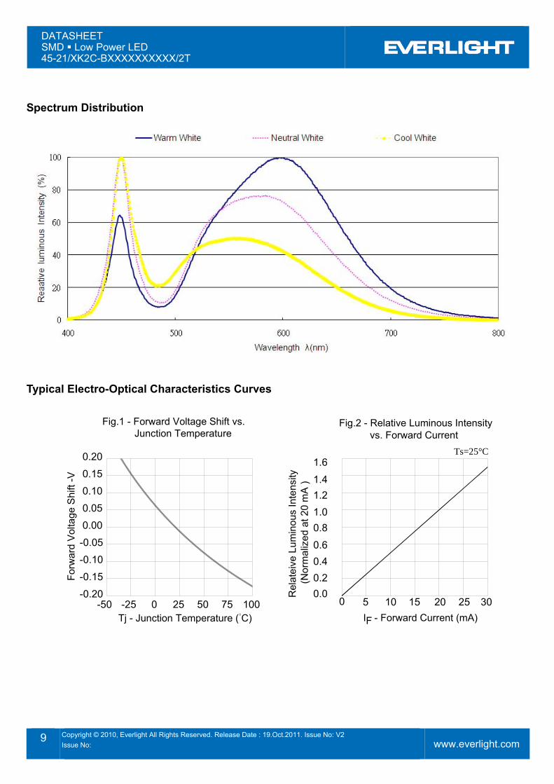
Spectrum Distribution
Typical Electro-Optical Characteristics Curves
Ts=25°C
-0.20
I - Forward Current (mA)Tj - Junction Temperature (°C)
Fig.2 - Relative Luminous Intensity vs. Forward Current
Fig.1 - Forward Voltage Shift vs. Junction Temperature
Rel
atei
ve L
umin
ous
Inte
nsity
(Nor
mal
ized
at 2
0 m
A )
Forw
ard
Vol
tage
Shi
ft -V
-50 -25 0 25 50 75 100
-0.15
-0.10
-0.05
0.00
0.05
0.10
0.15
0.20
F
0.00 5
0.20.40.6
0.81.01.21.4
1.6
10 15 20 25 30
DATASHEET SMD Low Power LED 45-21/XK2C-BXXXXXXXXXX/2T
10 Copyright © 2010, Everlight All Rights Reserved. Release Date : 19.Oct.2011. Issue No: V2 Issue No:
www.everlight.com
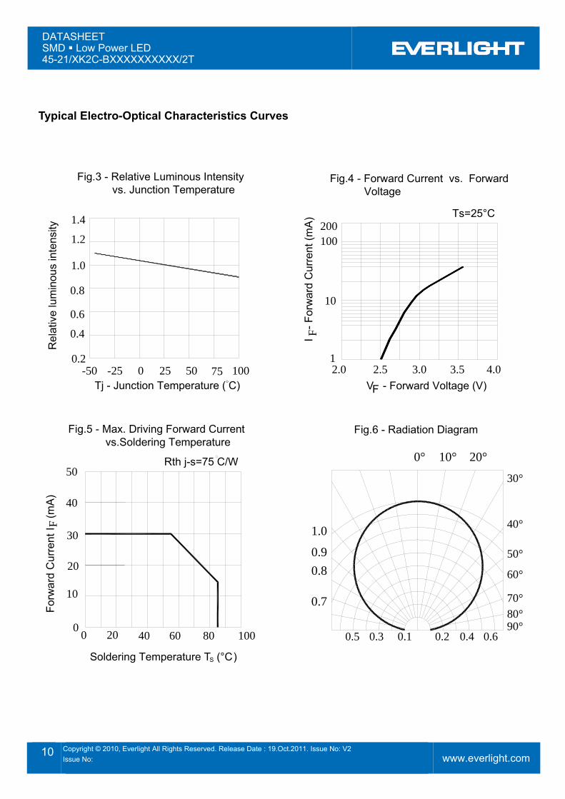
Typical Electro-Optical Characteristics Curves
2.0
10I
- Fo
rwar
d C
urre
nt (m
A)
-25-50 0 25 7550 100
Soldering Temperature T (°C )
00
Forw
ard
Cur
rent
I (
mA
)
10
20
40
30
804020 60 100
0.7
0.80.9
1.0
1
100
0.10.30.5 0.2 0.4
80°90°
0.6
50°
60°
70°
40°
20°0° 10°
30°
Ts=25°C
Rel
ativ
e lu
min
ous
inte
nsity
0.2
0.4
0.6
0.8
1.0
1.2
1.4
2.5
Fig.4 - Forward Current vs. Forward Voltage
Fig.3 - Relative Luminous Intensity vs. Junction Temperature
V - Forward Voltage (V) Tj - Junction Temperature (°C)
Fig.5 - Max. Driving Forward Current vs.Soldering Temperature
Fig.6 - Radiation Diagram
50
F
F
F
200
S
Rth j-s=75 C/W
3.0 3.5 4.0
DATASHEET SMD Low Power LED 45-21/XK2C-BXXXXXXXXXX/2T
11 Copyright © 2010, Everlight All Rights Reserved. Release Date : 19.Oct.2011. Issue No: V2 Issue No:
www.everlight.com
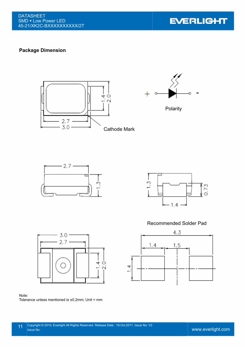
Package Dimension
Note: Tolerance unless mentioned is ±0.2mm; Unit = mm
Cathode Mark
Polarity
Recommended Solder Pad
DATASHEET SMD Low Power LED 45-21/XK2C-BXXXXXXXXXX/2T
12 Copyright © 2010, Everlight All Rights Reserved. Release Date : 19.Oct.2011. Issue No: V2 Issue No:
www.everlight.com
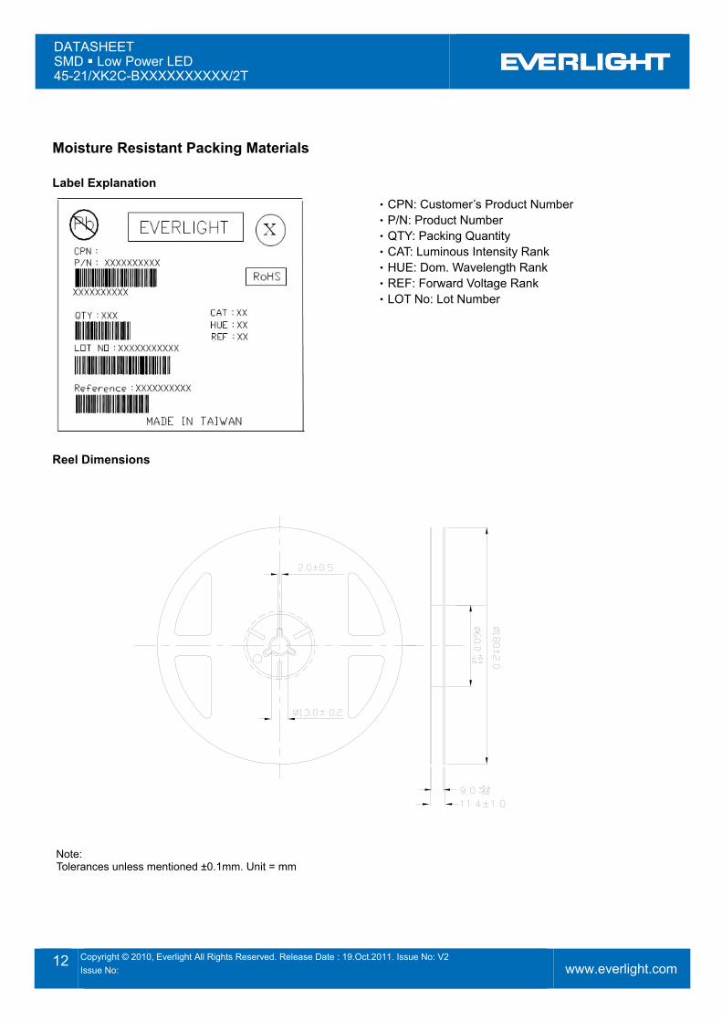
Moisture Resistant Packing Materials
Label Explanation
‧CPN: Customer’s Product Number ‧P/N: Product Number ‧QTY: Packing Quantity ‧CAT: Luminous Intensity Rank ‧HUE: Dom. Wavelength Rank ‧REF: Forward Voltage Rank ‧LOT No: Lot Number
Reel Dimensions
Note: Tolerances unless mentioned ±0.1mm. Unit = mm
DATASHEET SMD Low Power LED 45-21/XK2C-BXXXXXXXXXX/2T
13 Copyright © 2010, Everlight All Rights Reserved. Release Date : 19.Oct.2011. Issue No: V2 Issue No:
www.everlight.com
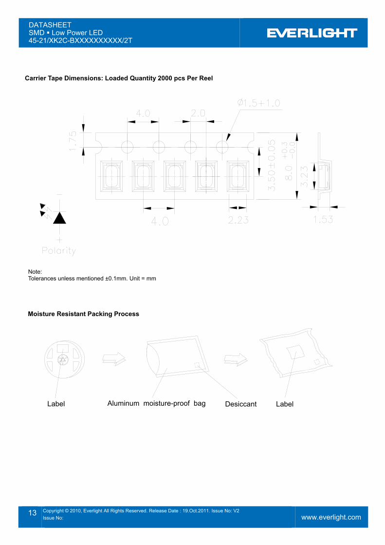
Carrier Tape Dimensions: Loaded Quantity 2000 pcs Per Reel
Note: Tolerances unless mentioned ±0.1mm. Unit = mm
Moisture Resistant Packing Process
Label Aluminum moisture-proof bag Desiccant Label
DATASHEET SMD Low Power LED 45-21/XK2C-BXXXXXXXXXX/2T
14 Copyright © 2010, Everlight All Rights Reserved. Release Date : 19.Oct.2011. Issue No: V2 Issue No:
www.everlight.com
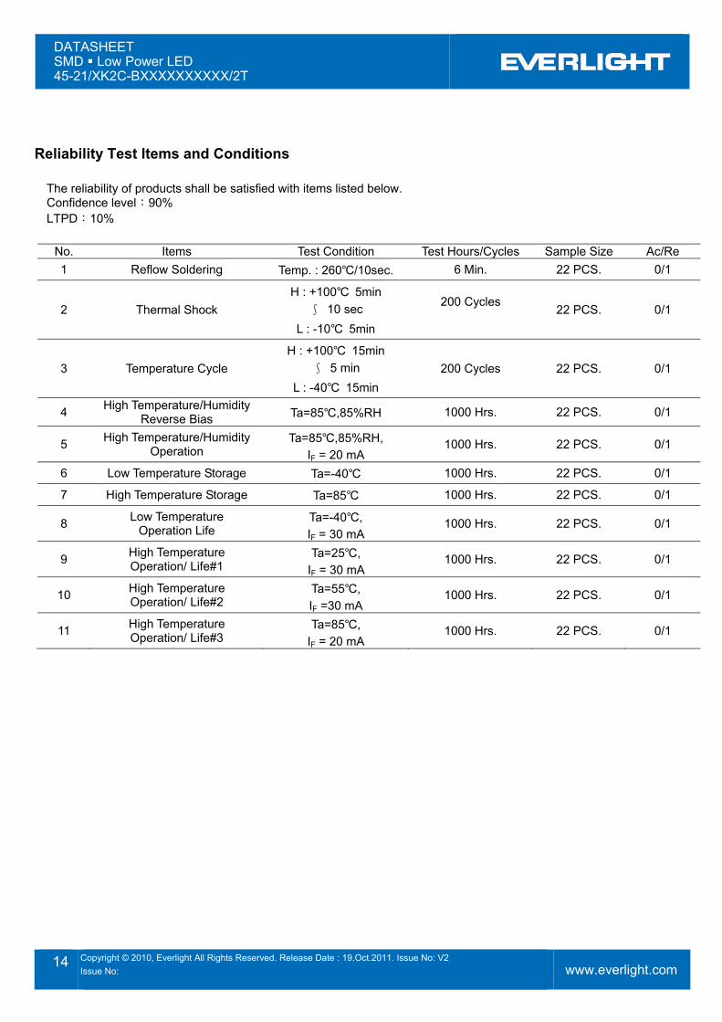
Reliability Test Items and Conditions
The reliability of products shall be satisfied with items listed below. Confidence level:90% LTPD:10%
No. Items Test Condition Test Hours/Cycles Sample Size Ac/Re 1 Reflow Soldering Temp. : 260℃/10sec. 6 Min. 22 PCS. 0/1
2 Thermal Shock H : +100℃ 5min
∫ 10 sec L : -10℃ 5min
200 Cycles 22 PCS. 0/1
3 Temperature Cycle H : +100℃ 15min
∫ 5 min L : -40℃ 15min
200 Cycles 22 PCS. 0/1
4 High Temperature/Humidity Reverse Bias Ta=85℃,85%RH 1000 Hrs. 22 PCS. 0/1
5 High Temperature/Humidity Operation
Ta=85℃,85%RH, IF = 20 mA
1000 Hrs. 22 PCS. 0/1
6 Low Temperature Storage Ta=-40℃ 1000 Hrs. 22 PCS. 0/1
7 High Temperature Storage Ta=85℃ 1000 Hrs. 22 PCS. 0/1
8 Low Temperature Operation Life
Ta=-40℃, IF = 30 mA
1000 Hrs. 22 PCS. 0/1
9 High Temperature Operation/ Life#1
Ta=25℃, IF = 30 mA
1000 Hrs. 22 PCS. 0/1
10 High Temperature Operation/ Life#2
Ta=55℃, IF =30 mA
1000 Hrs. 22 PCS. 0/1
11 High Temperature Operation/ Life#3
Ta=85℃, IF = 20 mA
1000 Hrs. 22 PCS. 0/1
DATASHEET SMD Low Power LED 45-21/XK2C-BXXXXXXXXXX/2T
15 Copyright © 2010, Everlight All Rights Reserved. Release Date : 19.Oct.2011. Issue No: V2 Issue No:
www.everlight.com
Precautions for Use
1. Over-current-proof Customer must apply resistors for protection; otherwise slight voltage shift will cause big current change (Burn out will happen).
2. Storage 2.1 Do not open moisture proof bag before the products are ready to use. 2.2 Before opening the package: The LEDs should be kept at 30℃ or less and 90%RH or less.
2.3 After opening the package: The LED's floor life is 168 Hrs under 30℃ or less and 60% RH or less. If unused LEDs remain, it should be stored in moisture proof packages.
2.4 If the moisture absorbent material (silica gel) has faded away or the LEDs have exceeded the storage time, baking treatment should be performed using the following conditions. Baking treatment: 60±5℃ for 24 hours.
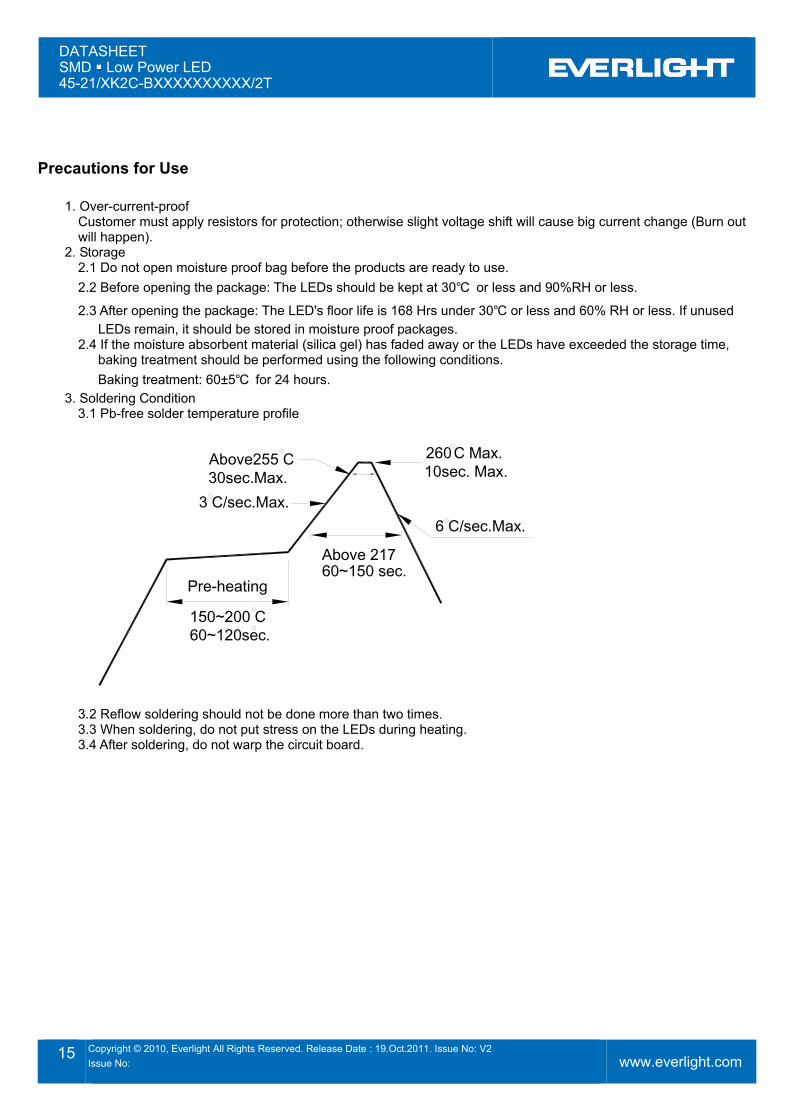
3. Soldering Condition 3.1 Pb-free solder temperature profile
260 Max.10sec. Max.
6 C/sec.Max.
Above255 C30sec.Max.
C
Above 21760~150 sec.
3 C/sec.Max.
Pre-heating
150~200 C60~120sec.
3.2 Reflow soldering should not be done more than two times. 3.3 When soldering, do not put stress on the LEDs during heating. 3.4 After soldering, do not warp the circuit board.
DATASHEET SMD Low Power LED 45-21/XK2C-BXXXXXXXXXX/2T
16 Copyright © 2010, Everlight All Rights Reserved. Release Date : 19.Oct.2011. Issue No: V2 Issue No:
www.everlight.com
4. Soldering Iron Each terminal is to go to the tip of soldering iron temperature less than 350℃ for 3 seconds within once in less than the soldering iron capacity 25W. Leave two seconds and more intervals, and do soldering of each terminal. Be careful because the damage of the product is often started at the time of the hand solder.
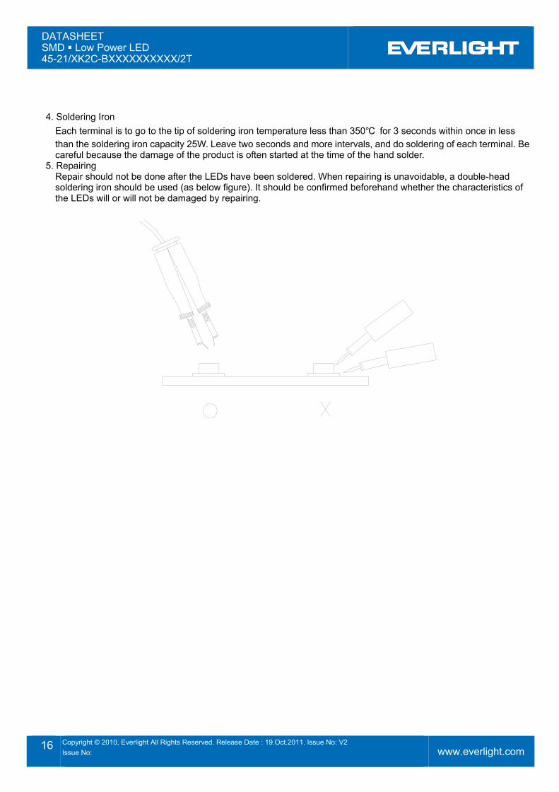
5. Repairing Repair should not be done after the LEDs have been soldered. When repairing is unavoidable, a double-head soldering iron should be used (as below figure). It should be confirmed beforehand whether the characteristics of the LEDs will or will not be damaged by repairing.