Embed Size (px)
Citation preview

Special bracket can be mounted.
Threaded for bottom mounting
Electrical entry is availablefrom four directions
SM
C
1
∗ When shipped from our factory, the electrical entry is set in the IN port side.
Wiring Variations
Wiring Specifications (Class B coil)
Lined Up by Compact Design
Grommet DIN terminal
Conduit Conduit terminal VCA20Class 2
VCA30Class 3
VCA40Class 4
Series VCADirect Operated 2 Port Solenoid Valve
For Air
Large flow rate: C value 1.1 to 7.7 dm3/(s·bar)
Improved durability (Nearly twice the life of the previous series)Resistance of moving parts has been reduced.Service life and wear resistance are improved.
Built-in surge voltage suppressor
• Noise prevention • Burn-out prevention
Built-in rectifying circuit (AC)
New compact coil reduces the overall sizeand weight of the valve.
Compact and lightweight
Flame resistance equivalent toUL94 standard V-0
Flame resistant molded coil material
Special construction reduces
operating resistance.
Enclosure: DusttightLow jetproof (Equivalent to IP65)
317
Electrical entry directions
A variety of wiring optionsGrommet, DIN terminal,Conduit, Conduit terminal
VX2
VXD
VXZ
VXE
VXP
VXR
VXH
VXF
VX3
VXA
VCH�
VDW
VQ
LVM
VCA
VCB
VCL
VCS
VCW
Courtesy of Steven Engineering, Inc.-230 Ryan Way, South San Francisco, CA 94080-6370-Main Office: (650) 588-9200-Outside Local Area: (800) 258-9200-www.stevenengineering.com

Direct Operated 2 Port Solenoid Valve For Air
Series VCA
For air
234
Class 2Class 3Class 4
Series
NilA
General airDry air
Fluid
VC A 2 1 1 G 3 02
NilF
NoneFoot type bracket
Option
NilB
NoneSlotted locking type (Tool required)
Manual override
NilFNT
RcG
NPTNPTF
Valve modelVCA21VCA31VCA41
Thread type (for single unit only)
Symbol02030406
Port size1/4 (8A) 3/8(10A)1/2(15A)3/4(20A)
Class 2�
———
Class 3�
�
——
Class 4—�
�
�
Port size
Symbol345710
Orifice dia. (mmø)3457
10
Class 2�
—�
——
Class 3—�
—�
—
Class 4——�
�
�
Orifice size
12345678J
100 VAC200 VAC110 VAC220 VAC24 VDC12 VDC
240 VAC48 VAC
230 VAC
Voltage
1
N.C.
2
1
Valve type
∗ Refer to the below table for orifice and port size combinations.
3
�
—
—
—
—
—
4
—
�
�
—
—
—
5
�
—
—
�
�
—
7
—
�
�
�
�
—
10
—
—
—
�
�
�
1/4 ( 8A)
1/4 ( 8A)
3/8 (10A)
3/8 (10A)
1/2 (15A)
3/4 (20A)
ClassOrifice diameter (mmø)
2
3
4
Table (1) Orifice diameter and Port Size Combinations
Port size
∗ Bracket is packed in the same container as the main body. Refer to the table (2) if a bracket is ordered separately.
Table (2) Bracket Assembly Part No.
∗ Mounting screws (2 pcs.)
∗ Please consult with SMC regarding other voltages.
Electrical entryG – Grommet C – Conduit
Connector
∗ All types are equipped with surge voltage suppressor.
T – Conduit terminalTL – Conduit terminal with
indicator light
D – DIN terminalDL – DIN terminal with
indicator lightDO – DIN terminal
(without connector, with gasket)
NilQ
—CE compliant
CE compliant
Made to order specificationsFor details, refer to page 319.
Bracket assembly part no.VCA20-12-1AVCA30-12-1AVCA40-12-1A
318
Series VC
How to Order Valves (Single Unit)
7-02-30-VCA20.qxd 09.10.1 1:27 PM Page 1
Courtesy of Steven Engineering, Inc.-230 Ryan Way, South San Francisco, CA 94080-6370-Main Office: (650) 588-9200-Outside Local Area: (800) 258-9200-www.stevenengineering.com

Standard Specifications
Valve constructionFluidWithstand pressure (MPa)Body materialSeal materialAmbient temperature (°C)Fluid temperature (°C)EnclosureEnvironmentValve leakage (cm3/min) (ANR)Exterior leakage (cm3/min) (ANR)Mounting orientationVibration/Impact resistance (m/s2)Rated voltageAllowable voltage fluctuationCoil insulation typePower consumption
Apparent power
Val
ve
spec
ifica
tions
Co
il sp
ecifi
catio
ns
Direct operated poppet Air, Inert gas, Low vacuum (133 Pa·abs)
2.0Al
HNBR–20 to 60
–10 to 60 (No freezing)Dusttight, low jetproof (equivalent to IP65)
Location without corrosive or explosive gases0.2 or less0.2 or less
Unrestricted30/150 or less
24 VDC, 12 VDC, 100 VAC, 110 VAC, 200 VAC, 220 VAC, 230 VAC (50/60 Hz)±10% of rated voltage
Class BVCA 2: 6.5 W, VCA 3: 8 W, VCA 4: 11.5 W
VCA 2: 7.5 VA, VCA 3: 10 VA, VCA 4: 13 VA
Characteristic Specifications
Made to Order Specifications
VCA(for air)2 port
solenoidvalve
ClassModel
354757
10
Orificediameter(mmø)
1.0 0.151.0 0.151.0 0.3 0.15
1.12.91.95.03.05.47.7
0.450.210.240.160.350.270.23
0.290.680.451.2 0.781.4 1.9
Max. operating pressure
differential (MPa)
Flow characteristics
C [dm3/(s·bar)] b CvPort size
1/4 ( 8A)
1/4 ( 8A)3/8 (10A)
3/8 (10A)1/2 (15A)3/4 (20A)
2
3
4
Note 1) Mass values are for the grommet type.
Note) Fluid: Air. Refer to VCW for model numbers and characteristics.
Note) Refer to VCW for characteristic specifications and models.
Note) Please consult with SMC when using. Not available for manual operation.
Max.operatingpressure
(MPa)
1.0
1.0
1.0
Mass(kg)
0.21
0.30
0.50
DC
AC50 Hz60 Hz
Normally open (N.O.) specifications
Oil-free specifications
Non-leak (10-6 Pa·m3/sec), vacuum (0.1 Pa·abs) specifications
VCW �–��–�– �– –�–X35234
AL
Coil orientation variations
VCA 1�–���–�–��–�–�234
X23X64X65
Rotated 180°Rotated 90°Rotated 270°
Standard
X65
X23
X64
IN
VCA 1A–��–�– �–�–X15234
VCW 2–���–�– �–��–X43234
Note 2)
Note 1)
Note 1) Since AC coil uses a rectifying circuit, there is no difference in apparent power between inrush and holding.Note 2) Vibration resistance ···· Conditions when tested with one sweep of 10 to 300 Hz in the axial direction and
at a right angle to the armature, in both energized and deenergized states. No malfunction occured when tested. (Value at initial state)
Impact resistance ······· Conditions when tested with a drop tester in the axial direction and at a right angle to the armature, one time each in energized and deenergized states. No malfunction occured when tested. (Value at the initial state).
Made toOrder
Note 1)
319
Series VCADirect Operated 2 Port Solenoid ValveFor Air
VX2
VXD
VXZ
VXE
VXP
VXR
VXH
VXF
VX3
VXA
VCH�
VDW
VQ
LVM
VCA
VCB
VCL
VCS
VCW
Courtesy of Steven Engineering, Inc.-230 Ryan Way, South San Francisco, CA 94080-6370-Main Office: (650) 588-9200-Outside Local Area: (800) 258-9200-www.stevenengineering.com

Construction
Bracket Assembly Dimensions
No.
1
2
3
4
5
Solenoid coil
Armature assembly
Return spring
O-ring
Body
Description
Component Parts
q
w
r
e
t
A
C
J
B D
2 x øHValve mounting hole
4 x ø6
Valve mounting screws
1.5
IN
Material
—
Stainless steel, HNBR, PPS
Stainless steel
HNBR
Aluminum
Bracket Mounting Dimensions/Bracket Material: Stainless SteelAssembly part no.
VCA20-12-1A
VCA30-12-1A
VCA40-12-1A
A
41
48
50
B
52
56
62
C
30
36
38
D
40
44
50
H
4.5
5.5
5.5
J
6
7
7
∗ 2 mounting screws (for mounting brackets) are included in bracket part no.
(mm)
320
Series VCA
Courtesy of Steven Engineering, Inc.-230 Ryan Way, South San Francisco, CA 94080-6370-Main Office: (650) 588-9200-Outside Local Area: (800) 258-9200-www.stevenengineering.com

Dimensions
Grommet: G Conduit: C
DIN terminal: D Conduit terminal: T
D
E
CR
LA
Q F
B
K
2 x PPort size
2 x PPort size
D
E
A
G1/2
G1/2
2 x MThread depth 6
Manual override
L
K 2 x MThread depth 6
L
K 2 x MThread depth 6
CR
Approx. 300
FF
QS
(S) ± 2
ER
App
rox.
44
C RC
A
D
B B2 x PPort size
E
AD 2 x P
Port size
G1/2
Port size G1/2
U
Compatible heavy-duty cordCable O.D. ø6 to ø12
IN
Manual override
2
25
34
L
K 2 x MThread depth 6
Q F
B
Approx. 280
25
Model
18243035
PPort size
1/41/4, 3/83/8, 1/2
3/4
Q27303232
R 40485658.5
Q46505252
R 36445355.5
Q63666969
R 35425153.5
S51545757
Q98
101104104
R36 44 53 55.5
S68717474
U 81 91.5101 103.5
41506068
64768691
28344040
11.5141517.5
15172020
20.5253034
12.8192323
M4M5M5M5
Electrical entry
Grommet: G Conduit: C DIN terminal: D Conduit terminal: T
(mm)
VCA21VCA31
VCA41
(Q) ± 2
A B C D E F K L M
321
Series VCADirect Operated 2 Port Solenoid ValveFor Air
VX2
VXD
VXZ
VXE
VXP
VXR
VXH
VXF
VX3
VXA
VCH�
VDW
VQ
LVM
VCA
VCB
VCL
VCS
VCW
Courtesy of Steven Engineering, Inc.-230 Ryan Way, South San Francisco, CA 94080-6370-Main Office: (650) 588-9200-Outside Local Area: (800) 258-9200-www.stevenengineering.com

How to Order Valves (VCA20)
How to Order Manifold (VCA20)
VV2C A 2 02
VC A 2 3 1 G
For air
12345678J
100 VAC200 VAC110 VAC220 VAC24 VDC12 VDC
240 VAC48 VAC
230 VAC
VoltageGCT
TLD
DLDO
GrommetConduitConduit terminalConduit terminal with indicator lightDIN terminalDIN terminal with indicator lightDIN terminal (without connector, with gasket)
Electrical entry
02
3
For air
2 Class 2
Series
02
10
2 stations
10 stations
Stations
... ...
02 1/4 (8A)
OUT port size
NilFNT
RcG
NPTNPTF
Thread type
Electrical entryNilT
Grommet, Conduit, DINConduit terminal
NilQ
—CE compliant
CE compliant
NilQ
—CE compliant
CE compliant
NilA
SideFront
IN port direction
How to Order Manifold AssemblyEnter the mounting valve and option part numbersunder the manifold base part number.
<Ordering Example>VV2CA2-0502 ···········∗ VCA23-5G-3 ···········
1 set Manifold part no.5 sets Valve part no. (Stations 1 to 5)
D side
U side
1
2
3
4
5
“∗” is the symbol for assembly. Add an “∗” in front of the part numbers for solenoid valves, etc., to be mounted.
Enter together in order, counting from station 1 on the D side.
2 Class 2
Series
3 N.C. for manifold
Valve type
NilA
General airDry air
Fluid
∗ Please consult with SMC regarding other voltages.
∗ All types equipped with surge voltage suppressor.
NilB
NoneSlotted locking type (tool required)
Manual override
Symbol35
Orifice dia. (mmø) 35
Orifice size
Series VCA
322
7-02-30-VCA20.qxd 09.10.1 1:27 PM Page 2
Courtesy of Steven Engineering, Inc.-230 Ryan Way, South San Francisco, CA 94080-6370-Main Office: (650) 588-9200-Outside Local Area: (800) 258-9200-www.stevenengineering.com

How to Order Valves (VCA30/40)
How to Order Manifold (VCA30/40)
VV2C A 02NilQ
—CE compliant
CE compliantFor air
03VC A 5 1 G
For air
GCT
TLD
DLDO
GrommetConduitConduit terminalConduit terminal with indicator lightDIN terminalDIN terminal with indicator lightDIN terminal (without connector, with gasket)
Electrical entry
3 4
3
34
Class 3Class 4
Series
02
10
2 stations
10 stations
Stations
... ...
NilFNT
RcG
NPTNPTF
Thread type
NilA
SideFront
IN port direction
How to Order Manifold Assembly
<Ordering Example>VV2CA3-05 ···············∗ VCA35-5G-4-03 ······
D side
U side
1
2
3
4
5
Enter the mounting valve and option part numbersunder the manifold base part number.
1 set Manifold part no.5 sets Valve part no. (Stations 1 to 5)
“∗” is the symbol for assembly. Add an “∗” in front of the part numbers for solenoid valves, etc., to be mounted.
Enter together in order, counting from station 1 on the D side.
34
Class 3Class 4
Series
5 N.C. for manifold
Valve type
NilA
General airDry air
Fluid
12345678J
100 VAC200 VAC110 VAC220 VAC24 VDC12 VDC
240 VAC48 VAC
230 VAC
Voltage
∗ Please consult with SMC regarding other voltages.
∗ All types equipped with surge voltage suppressor.
NilB
NoneSlotted locking type (Tool required)
Manual override
Symbol45710
Orifice dia. (mmø) 457
10
Class 3�
—�
—
Class 4—�
�
�
Orifice size
Symbol030406
Size3/8 (10A) 1/2 (15A)
3/4 (20A)
Class 3�
�
—
Class 4—�
�
Port size (OUT)
NilFNT
RcG
NPTNPTF
Thread type
NilQ
—CE compliant
CE compliant
323
Series VCADirect Operated 2 Port Solenoid ValveFor Air
VX2
VXD
VXZ
VXE
VXP
VXR
VXH
VXF
VX3
VXA
VCH�
VDW
VQ
LVM
VCA
VCB
VCL
VCS
VCW
7-02-30-VCA20.qxd 09.10.1 1:27 PM Page 3
Courtesy of Steven Engineering, Inc.-230 Ryan Way, South San Francisco, CA 94080-6370-Main Office: (650) 588-9200-Outside Local Area: (800) 258-9200-www.stevenengineering.com

Dimensions: VCA20 Manifold
5
2532
2
l =
300
l =
280
(68)
5133
19
(98)
6248
26.4
27
21
513
55
14
25 19.5
72
P=28.5 24.5
42
38.5
37
2512
.5
∗ Plug provided on U side at the time of shipment.
∗ Plug provided on U side at the time of shipment.Mounting holes
2 x ø 5.6
L2 (Front ported)L1 (Front ported)L2 (Side ported)L1 (Side ported)
Manual overrideManual override
IN port (Side ported)2 x Rc3/8
D side U sideStations 1 2 3 4 5 n
(Front ported)IN port2 x 3/8
OUT portn x 1/4
Mounting valve: for conduit terminal (P = 34.5)
2 67.577.5
107.5117.5
3 96
106136146
4124.5134.5164.5174.5
5153163193203
6181.5191.5221.5231.5
7210220250260
8238.5248.5278.5288.5
10295.5305.5335.5345.5
9267277307317
IN port direction
Side ported
Front ported
L1
L2
L1
L2
Dimensions (mm)Side ported: L1 = n x 28.5 + 10.5 L2 = n x 28.5 + 20.5Front ported: L1 = n x 28.5 + 50.5 L2 = n x 28.5 + 60.5
L n
2 73.583.5
113.5123.5
3108118148158
4142.5152.5182.5192.5
5177187217227
6211.5221.5251.5261.5
7246256286296
8280.5290.5320.5330.5
10349.5359.5389.5399.5
9315325355365
IN port direction
Side ported
Front ported
L1
L2
L1
L2
Dimensions (mm)Side ported: L1 = n x 34.5 + 4.5 L2 = n x 34.5 + 14.5Front ported: L1 = n x 34.5 + 44.5 L2 = n x 34.5 + 54.5
L n
(When the electrical entry of a valve to be mounted is conduit terminal.)
Series VCA
324Courtesy of Steven Engineering, Inc.-230 Ryan Way, South San Francisco, CA 94080-6370-Main Office: (650) 588-9200-Outside Local Area: (800) 258-9200-www.stevenengineering.com

Dimensions: VCA30/40 Manifold
V(Y
)
l =
280
L1 (Front ported)L2 (Front ported)
HG
C BA
E
J3P = K (Pitch)
L
1 1
1
22 2 2
Ql
= 3
00S
W T RZ
M
U
5.5
5.5
L2 (Side ported)
L1 (Side ported)
2 x 1/2 (VCA30), 3/4 (VCA40)IN port (Side ported)∗ Plug provided on U side at the time of shipment.
16J1
Manual override
(X)
J2
2532
F
N
2 x 1/2 (VCA30), 3/4 (VCA40)IN port (Front ported)∗ Plug provided on U side at the time of shipment.
2 x ø6.4Mounting holes
U sideD sideStations 1 2 3 4 5 n
n x 3/8, 1/2 (VCA30)n x 1/2, 3/4 (VCA40)OUT port
For manual override
Manual override
2103114139150117128161172
3138149174185158169202213
4173184209220199210243254
5208219244255240251284295
6243254279290281292325336
7278289314325322333366377
8313324349360363374407418
10383394419430445456489500
9348359384395404415448459
IN port direction
Side ported
Front ported
Side ported
Front ported
Model
VV2CA3
VV2CA4
Dimensions
L1
L2
L1
L2
L1
L2
L1
L2
L Dimension (mm)
n (stations)
Model
VV2CA3
VV2CA4
A
5562
Q
3032
R
3641
S
5052
T
3238
U
5457
V
6669
W
3036
Y
101104
X
7174
Z
65.571
Electrical entry
Grommet: G Conduit: C DIN terminal: D Conduit terminal: T
(mm)Dimensions
B
2931
C
3843
E
19.521
F
33 39.5
G
2631
H
3543
J2
39.543.5
K
3541
J3
57.565.5
J1
23.527
L
26.529
M
41.548
N
5055
FormulasVV2CA3Side ported: L1 = n x 35 + 33, L2 = n x 35 + 44Front ported: L1 = n x 35 + 69, L2 = n x 35 + 80VV2CA4Side ported: L1 = n x 41 + 35, L2 = n x 41 + 46Front ported: L1 = n x 41 + 79, L2 = n x 41 + 90
325
Series VCADirect Operated 2 Port Solenoid ValveFor Air
VX2
VXD
VXZ
VXE
VXP
VXR
VXH
VXF
VX3
VXA
VCH�
VDW
VQ
LVM
VCA
VCB
VCL
VCS
VCW
Courtesy of Steven Engineering, Inc.-230 Ryan Way, South San Francisco, CA 94080-6370-Main Office: (650) 588-9200-Outside Local Area: (800) 258-9200-www.stevenengineering.com

Manifold Exploded View
Series VCA20
Series VCA30/40
q
w
e
r
r
t
y
q
w
e
Mount it as shown above. Mounting orientation exists when mounting valves onto manifold base.
Gasket
Manifold body
Manifold base OUT port side
Manifold body
No.
1
2
3
4
M3 x 57VCA23�-���-�
VVCA20-3-1VV2CA2-���-�
Part no. Material
Steel
HNBR
Aluminum
Description
Cross-recessed head machine screw
Valve for manifold
Gasket
Manifold base
Note 1)
Note 1) Gasket e is included with manifold valve w.
No.
1
2
3
4
5
6
AXT632-69-1AXT632-69-2VVCA30-3A-04-2VVCA30-3A-04-1OR-2200-200-HVCA35�-��-�-��VVCA30-6-nVVCA30-4A-04-2VVCA30-4A-04-1
Material
Steel
Aluminum
HNBR
Steel
Aluminum
Material
Steel
Aluminum
HNBR
Steel
Aluminum
Mounting screw (side port)
Mounting screw (front port)
End plate assembly (D side, side port)
End plate assembly (D side, front port)
O-ring (for VCA30)
Manifold valve
Tie-rod
End plate assembly (U side, side port)
End plate assembly (U side, front port)
Series VCA30
AXT632-69-1AXT632-69-2VVCA40-3A-06-2VVCA40-3A-06-1OR-3200-200-HVCA45�-��-�-��VVCA40-6-nVVCA40-4A-06-2VVCA40-4A-06-1
Mounting screw (side port)
Mounting screw (front port)
End plate assembly (D side, side port)
End plate assembly (D side, front port)
O-ring (for VCA40)
Manifold valve
Tie-rod
End plate assembly (U side, side port)
End plate assembly (U side, front port)
Series VCA40
Note 2) O-ring e is included with manifold valve r. Note 2) O-ring e is included with manifold valve r.
Note 2) Note 2)
DescriptionNo.
1
2
3
4
5
6
Series VCA
DescriptionPart no. Part no.
326Courtesy of Steven Engineering, Inc.-230 Ryan Way, South San Francisco, CA 94080-6370-Main Office: (650) 588-9200-Outside Local Area: (800) 258-9200-www.stevenengineering.com
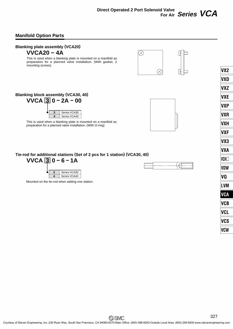
Manifold Option Parts
Blanking plate assembly (VCA20)
VVCA20 4A
Blanking block assembly (VCA30, 40)
Tie-rod for additional stations (Set of 2 pcs for 1 station) (VCA30, 40)
VVCA 3 0 6 1A
VVCA 3 0 2A 00
This is used when a blanking plate is mounted on a manifold as preparation for a planned valve installation. (With gasket, 2 mounting screws)
34
Series VCA30Series VCA40
This is used when a blanking plate is mounted on a manifold as preparation for a planned valve installation. (With O-ring)
34
Series VCA30Series VCA40
Mounted on the tie-rod when adding one station.
327
Series VCADirect Operated 2 Port Solenoid ValveFor Air
VX2
VXD
VXZ
VXE
VXP
VXR
VXH
VXF
VX3
VXA
VCH�
VDW
VQ
LVM
VCA
VCB
VCL
VCS
VCW
Courtesy of Steven Engineering, Inc.-230 Ryan Way, South San Francisco, CA 94080-6370-Main Office: (650) 588-9200-Outside Local Area: (800) 258-9200-www.stevenengineering.com