Embed Size (px)
Citation preview
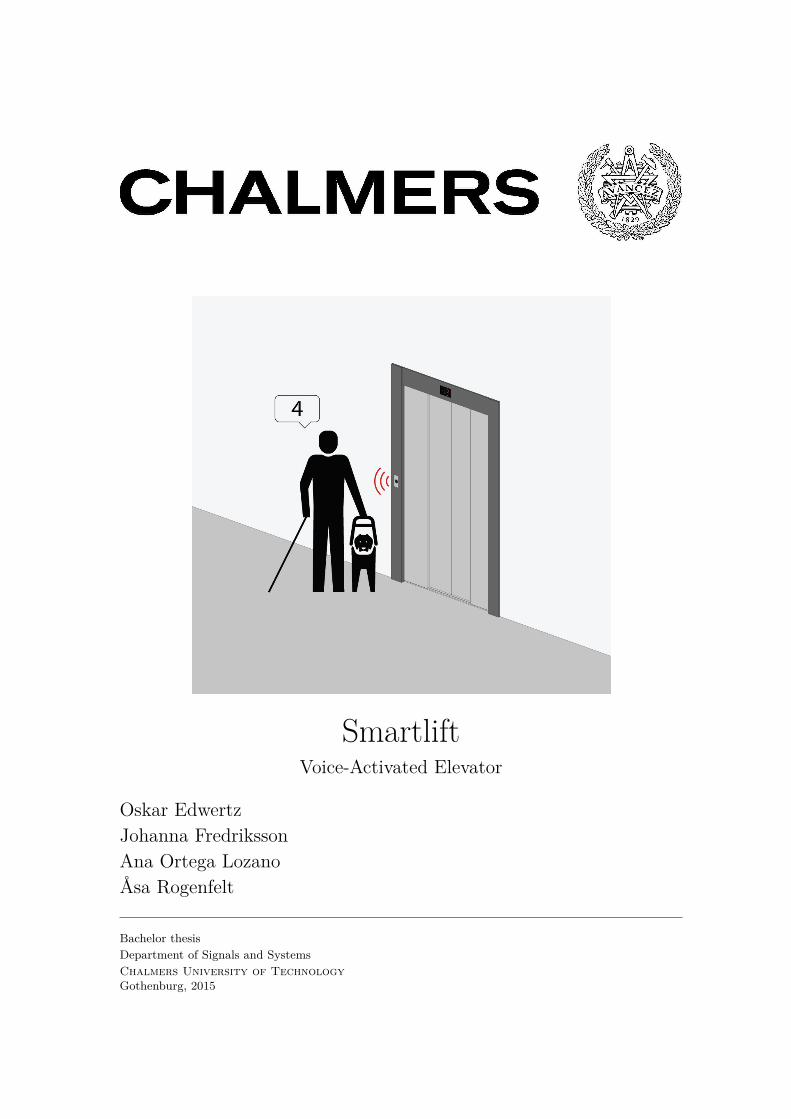
SmartliftVoice-Activated Elevator
Oskar EdwertzJohanna FredrikssonAna Ortega LozanoÅsa Rogenfelt
Bachelor thesisDepartment of Signals and SystemsChalmers University of TechnologyGothenburg, 2015
Smartlift-Voice activated elevator SSYX02-15-35 SSYX02-15-35
The Author grants to Chalmers Universityof Technology and University of Gothenburgthe non-exclusive right to publish the Workelectronically and in a non-commercial purposemake it accessible on the Internet. The Authorwarrants that he/she is the author to theWork, and warrants that the Work does notcontain text, pictures or other material thatviolates copyright law.
The Author shall, when transferring the rightsof the Work to a third party (for example apublisher or a company), acknowledge the thirdparty about this agreement. If the Authorhas signed a copyright agreement with a thirdparty regarding the Work, the Author war-rants hereby that he/she has obtained any nec-essary permission from this third party to letChalmers University of Technology and Univer-sity of Gothenburg store the Work electroni-cally and make it accessible on the Internet.
SmartliftVoice Activated Elevator
O. EdwertzJ. FredrikssonA. Ortega LozanoÅ. Rogenfelt
© O. Edwertz, MAY 2015© J. Fredriksson, MAY 2015© A. Ortega Lozano, MAY 2015© Å. Rogenfelt, MAY 2015
Examiner: Paolo Falcone
Chalmers University of TechnologyDepartment of Signals and SystemsSE-412 96 GöteborgSwedenTelephone + 46 (0)31-772 1000Department of Signals and SystemsGöteborg, Sweden May 2015
Front page picture courtesy of Martin Widerström©
Smartlift-Voice activated elevator SSYX02-15-35 SSYX02-15-35
AbstractAlthough general accessibility for disabled people has improved during the recent years,
the operation of standard elevators can still be enhanced. This report presents an upgradein the way of requesting destinations, which facilitates the operation for the passengers. Thesystem is implemented into a downscaled prototype, which uses a speech recognition unitbased on the methods of Mel Frequency Cepstral Coefficients (MFCC) and Dynamic TimeWarping (DTW). The design also includes a back-up option of using buttons. An originaldesign feature of this project is the fact that the selection of destinations is made while thepassengers are waiting for the elevator. This voice-operated elevator uses a novel algorithmfor sorting the requested destinations, a state machine to control the general logic and a step-per motor to move the elevator car. The report concludes that the designed system can beimplemented into a full-scale elevator with some minor adjustments.
Keywords: Speech Recognition, Elevator Control, Voice-operated, MFCC,DTW, Stepper Motor, State Machine
SammanfattningKan vi göra det enklare för personer med funktionshinder att anända hissar? Medan
allmän tillgänglighet för funktionshindrade har förbättrats under de senaste åren, finns detfortfarande mycket rum för förbättring kring användandet av hissar. Denna rapport presen-terar en nedskalad prototyp som förändrar hur vi efterfrågar våningsdestinationer. Systemetanvänder sig av en röstigenkänningsenhet, som bygger på metoder så som Mel Frequency Cep-stral Coefficients (MFCC) och Dynamic TimeWarping (DTW). Dessutom inkluderar designenvalmöjligheten att använda knappar. Ytterligare ett nytt inslag i detta projekt är det faktumatt valet av destinationer görs medan passagerarna väntar på hissen. Denna röst manövr-erade hiss använder en egendesignad algoritm för att sortera de begärda destinationerna, entillståndsmaskin som styr den allmänna logiken och en stegmotor som förflyttar hisskorgen.I rapporten dras slutsatsen att det avsedda systemet kan implementeras i en fullskalig hiss,med vissa justeringar.
Nyckelord: Röstigenkänning, Hisskontroll, Röststyrning, MFCC, DTW, Stegmo-tor, Tillståndsmaskin

Smartlift-Voice activated elevator SSYX02-15-35 SSYX02-15-35
Acknowledgement
We would like to thank,
Hakan Köroğlu for supporting us throughout the whole project and providing good feedback
Göran Stigler for helping out with the design and construction of the prototype
Erik Ström for giving advice on the speech recognition system
The Department of Signals and Systems at Chalmers University of Technology forproviding the necessary resources for finishing the project
The Language and Communication Division at Chalmers University of Technologyfor giving advice on the language and overall structure of the report
Comillas Pontifical University for answering technical questions about the project
ArduinoTM for developing the hardware needed in projects like this
Dustin for the programmable pulse generator, Copyright (C) 2008, Dustin. All rights reserved.Permitted use
Lastly, thank you to the microcontroller board company Raspberry Pi, a trademark of the Rasp-berry Pi Foundation.
Smartlift-Voice activated elevator SSYX02-15-35 SSYX02-15-35
ContentsAcronyms 1
1 Introduction 21.1 Background . . . . . . . . . . . . . . . . . . . . . . . . . . . . . . . . . . . . . . . . 21.2 Problem Description . . . . . . . . . . . . . . . . . . . . . . . . . . . . . . . . . . . 2
1.2.1 Task . . . . . . . . . . . . . . . . . . . . . . . . . . . . . . . . . . . . . . . . 21.2.2 Requirements . . . . . . . . . . . . . . . . . . . . . . . . . . . . . . . . . . . 2
1.3 Boundaries . . . . . . . . . . . . . . . . . . . . . . . . . . . . . . . . . . . . . . . . 3
2 System Architecture 42.1 Overall Design . . . . . . . . . . . . . . . . . . . . . . . . . . . . . . . . . . . . . . 42.2 Design and Implementation . . . . . . . . . . . . . . . . . . . . . . . . . . . . . . . 42.3 System Operation . . . . . . . . . . . . . . . . . . . . . . . . . . . . . . . . . . . . 5
3 Elevator Control Unit 73.1 Operation of the Elevator Control Unit . . . . . . . . . . . . . . . . . . . . . . . . 7
3.1.1 Conversion of signal from an activated sensor to a number for the SRU . . 73.1.2 Conversion of numbers from the SRU to signed numbers for the elevator
algorithm . . . . . . . . . . . . . . . . . . . . . . . . . . . . . . . . . . . . . 83.1.3 Elevator algorithm and storage of the array of target floors . . . . . . . . . 83.1.4 State Machine . . . . . . . . . . . . . . . . . . . . . . . . . . . . . . . . . . 93.1.5 Motion Control . . . . . . . . . . . . . . . . . . . . . . . . . . . . . . . . . . 10
3.2 Implementation . . . . . . . . . . . . . . . . . . . . . . . . . . . . . . . . . . . . . . 123.2.1 Implementation of Unit 1 and Unit 2 . . . . . . . . . . . . . . . . . . . . . . 123.2.2 Implementation of Unit 3 . . . . . . . . . . . . . . . . . . . . . . . . . . . . 123.2.3 Implementation of State Machine . . . . . . . . . . . . . . . . . . . . . . . . 133.2.4 Implementation of Motion Control . . . . . . . . . . . . . . . . . . . . . . . 153.2.5 Implementation of Motion Control in Initialising System State . . . . . . . 153.2.6 Reset Position Block . . . . . . . . . . . . . . . . . . . . . . . . . . . . . . . 15
3.3 Example of Operation with SRU . . . . . . . . . . . . . . . . . . . . . . . . . . . . 153.4 Verification of the ECU . . . . . . . . . . . . . . . . . . . . . . . . . . . . . . . . . 16
4 Speech Recognition Unit 174.1 State of the Art and Basic Signal Processing Theory . . . . . . . . . . . . . . . . . 174.2 Isolated Speech Recognition Algorithm . . . . . . . . . . . . . . . . . . . . . . . . . 18
4.2.1 Filtering . . . . . . . . . . . . . . . . . . . . . . . . . . . . . . . . . . . . . . 194.2.2 Voice Activity Detection . . . . . . . . . . . . . . . . . . . . . . . . . . . . . 204.2.3 Segmentation Process . . . . . . . . . . . . . . . . . . . . . . . . . . . . . . 204.2.4 Windowing . . . . . . . . . . . . . . . . . . . . . . . . . . . . . . . . . . . . 214.2.5 MFCC Generation . . . . . . . . . . . . . . . . . . . . . . . . . . . . . . . . 214.2.6 Dynamic Coefficients . . . . . . . . . . . . . . . . . . . . . . . . . . . . . . . 22
4.3 Classification Process . . . . . . . . . . . . . . . . . . . . . . . . . . . . . . . . . . . 234.4 Verification Process . . . . . . . . . . . . . . . . . . . . . . . . . . . . . . . . . . . . 244.5 Implementation Into Hardware . . . . . . . . . . . . . . . . . . . . . . . . . . . . . 25
5 Physical Construction and System Components 275.1 Construction of Prototype . . . . . . . . . . . . . . . . . . . . . . . . . . . . . . . . 275.2 Motor . . . . . . . . . . . . . . . . . . . . . . . . . . . . . . . . . . . . . . . . . . . 27
5.2.1 Precision . . . . . . . . . . . . . . . . . . . . . . . . . . . . . . . . . . . . . 285.2.2 Torque . . . . . . . . . . . . . . . . . . . . . . . . . . . . . . . . . . . . . . . 285.2.3 Rotational speed . . . . . . . . . . . . . . . . . . . . . . . . . . . . . . . . . 28
5.3 Motor driver . . . . . . . . . . . . . . . . . . . . . . . . . . . . . . . . . . . . . . . 295.4 Sensors . . . . . . . . . . . . . . . . . . . . . . . . . . . . . . . . . . . . . . . . . . 30
Smartlift-Voice activated elevator SSYX02-15-35 SSYX02-15-35
5.5 LEDs . . . . . . . . . . . . . . . . . . . . . . . . . . . . . . . . . . . . . . . . . . . 315.6 Buttons . . . . . . . . . . . . . . . . . . . . . . . . . . . . . . . . . . . . . . . . . . 325.7 Microphone . . . . . . . . . . . . . . . . . . . . . . . . . . . . . . . . . . . . . . . . 335.8 Speaker . . . . . . . . . . . . . . . . . . . . . . . . . . . . . . . . . . . . . . . . . . 335.9 Microcontrollers . . . . . . . . . . . . . . . . . . . . . . . . . . . . . . . . . . . . . 33
6 Environment and Sustainability 34
7 Improvements and Issues in Upscaling 357.1 Required Improvements in the Downscaled Prototype . . . . . . . . . . . . . . . . 357.2 Upscaling for a Real Elevator System . . . . . . . . . . . . . . . . . . . . . . . . . . 36
8 Discussion and Evaluation of the Achievements 38
9 Concluding Remarks 40
References 41
Appendix A Drawing of the construction 43
Appendix B Layout and functions of the motor driver 44
Appendix C Unit 1, Unit 2 and Unit 3 Simulink Models adapted for SRU 45
Appendix D State Machine Simulink Model 46
Appendix E Unit 1, Unit 2 and Unit 3 Simulink Modelsadapted for Buttons 47
Appendix F Inventory list 48
Appendix G Unit 1 Code for the Case of Operation with SRU 49
Appendix H Unit 2 Code for the Case of Operation with SRU 50
Appendix I Unit 1 Code for the Case of Operation with Buttons 52
Appendix J Unit 2 Code for the Case of Operation with Buttons 53
Appendix K Elevator Algorithm Code 54
Appendix L Delete another floor MATLAB Function Code 65
Appendix M Counting Steps MATLAB Function Code 66
Appendix N Speech Recognition Code 67
Smartlift-Voice activated elevator SSYX02-15-35 SSYX02-15-35
Acronyms
DFT Discrete-Time Fourier transform. 21
DTW Dynamic Time Warping. , 17, 40
ECU Elevator Control Unit. , 4, 5, 6, 7, 9, 11, 12, 13, 16, 36, 38
FBE Filter Bank Energy. 22
GaAs Gallium arsenide. 30
IDCT Inverse Discrete Cosine Transform. 22
IR Infrared. 30
LED Light-Emitting Diode. , 30, 31, 32, 33
LPC Linear Predictive Coding. 17
MFCC Mel Frequency Cepstral Coefficients. , 17, 18, 40
NPN Negative-Positive-Negative transistor. 30
PID Proportional-Integral-Derivative. 36
RMS Root Mean Square. 33
SMD Surface Mount Device. 29
SRU Speech Recognition Unit. , 4, 5, 7, 12, 16, 17, 18, 22, 24, 26, 35, 37, 38
VAD Voice Activity Detection. 19
1
Smartlift-Voice activated elevator SSYX02-15-35 SSYX02-15-35
1 Introduction
The aim of this project is to develop a voice-activated elevator. To be able to show the elevatoralgorithm and the speech recognition system, a prototype is designed and built. This sectioncontains the background, the problem descriptions and the boundaries set for this project.
1.1 Background
Despite many advantages provided by modern elevator systems, operating an elevator can be achallenging task for certain groups of people. The control of the elevator panel might be difficult touse if the person is for example blind or physically impaired. In such cases, it would be convenientif the elevator could be controlled with voice commands.
The invention of a voice-activated elevator has already been made before. Nowadays, it is evenpossible to buy a complete voice-activated control unit and install it on an existing elevatorsystem. One example of this is talk2lift1. However, the Smartlift project differs from other voice-controlled elevators in the sense that it is a downscaled prototype. For that reason, the integrationof speech recognition with the logic and control of the elevator in low-cost hardware is a challengingproblem. Also due to downscaling, some issues such as safety and motor control, will vary from areal elevator. Moreover, the designed system has new features if compared to other voice-activatedelevators. In particular, the passenger chooses the desired floor before entering the elevator. Thismakes it necessary to develop a novel elevator control algorithm.
1.2 Problem Description
In this subsection, the project task and requirements are described. The task and the requirementshave been defined based on the areas of knowledge of the project group members.
1.2.1 Task
The aim of this project is to build and control a downscaled prototype of an elevator with tenfloors. The position and speed of the elevator should automatically be adjusted to sustain a niceand smooth ride for the hypothetical passengers. Also, the target floors have to be sorted in away to minimise the travelled distance of the elevator car, which thereby reduces both the energyconsumption and the waiting times for the passengers. Furthermore, the elevator should be ableto be operated with a speech recognition unit, as well as standard buttons that could replace thisunit when desired.
1.2.2 Requirements
The following requirements are established for the prototype:
• Recognition of the numbers 1-10
• Recognition of voices from both men and women (children not included)
• Function without voice operation, by using buttons
• A position accuracy of 0.5 cm
• Smooth movement of the elevator to make a pleasant ride for the hypothetical passengers1A company that produces speech control systems for elevators, http://www.talk2lift.com
2
Smartlift-Voice activated elevator SSYX02-15-35 SSYX02-15-35
• Minimising the distance travelled of the elevator car by sorting the requested floors in anintelligent way
• Ability to keep ten requests at the memory at all times
• A construction cost below 5000 SEK
1.3 Boundaries
Since the goal of the project is to build a downscaled prototype of an elevator, some physicalboundaries need to be taken into consideration. In a normal-sized elevator system, the differentfloors are separated from each other. Therefore, one microphone would be required in each floor.However, due to the small size of the prototype and the wide scope of a microphone, only a singlemicrophone is used in the project. For that reason, only one guest in a specific floor can speak ata time. It is also important to mention that the designed system can only receive one requestedfloor each time a proximity sensor is activated.
Speech recognition is a challenging task, which requires deep knowledge in the field. Most of thecomplication in speech recognition is connected to the complexity of the language. In this project,the language part is narrowed down. Hence, only numbers are treated by the system and only theEnglish language is recognised.
The differences in frequencies and vowel space between adults and children make it difficult tocreate an accurate system for all ages. It has been shown that, when using a model designed foradults, the speech from a child has up to five times higher failure rate [4]. It is hence decided thatthe system only focuses on speech from adults.
3
Smartlift-Voice activated elevator SSYX02-15-35 SSYX02-15-35
2 System Architecture
This section describes the implemented design in the project Smartlift, including an overall pictureof the different units developed.
2.1 Overall Design
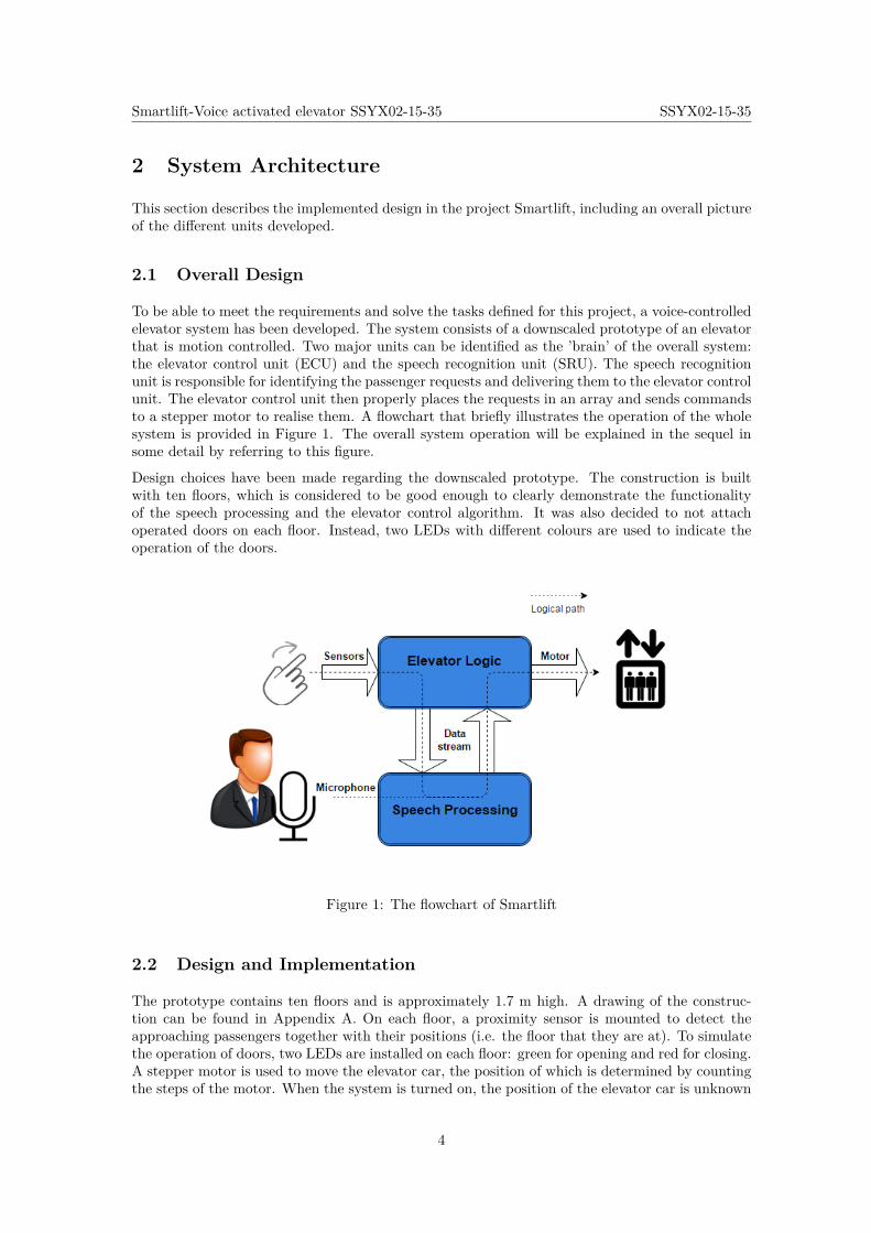
To be able to meet the requirements and solve the tasks defined for this project, a voice-controlledelevator system has been developed. The system consists of a downscaled prototype of an elevatorthat is motion controlled. Two major units can be identified as the ’brain’ of the overall system:the elevator control unit (ECU) and the speech recognition unit (SRU). The speech recognitionunit is responsible for identifying the passenger requests and delivering them to the elevator controlunit. The elevator control unit then properly places the requests in an array and sends commandsto a stepper motor to realise them. A flowchart that briefly illustrates the operation of the wholesystem is provided in Figure 1. The overall system operation will be explained in the sequel insome detail by referring to this figure.
Design choices have been made regarding the downscaled prototype. The construction is builtwith ten floors, which is considered to be good enough to clearly demonstrate the functionalityof the speech processing and the elevator control algorithm. It was also decided to not attachoperated doors on each floor. Instead, two LEDs with different colours are used to indicate theoperation of the doors.
Figure 1: The flowchart of Smartlift
2.2 Design and Implementation
The prototype contains ten floors and is approximately 1.7 m high. A drawing of the construc-tion can be found in Appendix A. On each floor, a proximity sensor is mounted to detect theapproaching passengers together with their positions (i.e. the floor that they are at). To simulatethe operation of doors, two LEDs are installed on each floor: green for opening and red for closing.A stepper motor is used to move the elevator car, the position of which is determined by countingthe steps of the motor. When the system is turned on, the position of the elevator car is unknown
4
Smartlift-Voice activated elevator SSYX02-15-35 SSYX02-15-35
and therefore a reference sensor is needed. The sensor is placed at the first floor. When the systemis turned on, the elevator car starts moving down until the sensor gets activated and the positionis then known. Ten buttons are also used to facilitate the operation of the elevator without theSRU. Because of downscaling, only one microphone and speaker are used. A display is used toshow the array of the elevator. The construction is placed and stabilised on a wooden platform,where the hardware is also located.
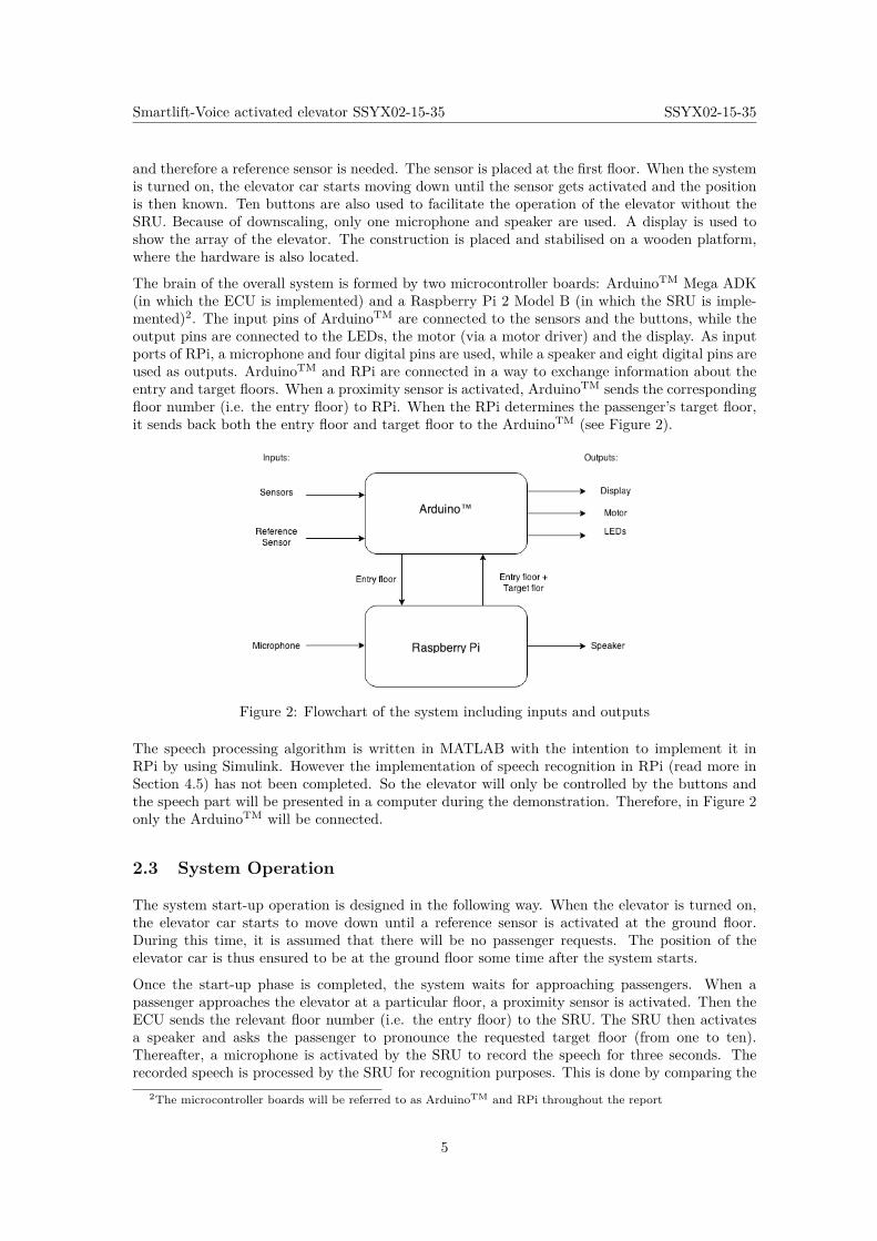
The brain of the overall system is formed by two microcontroller boards: ArduinoTM Mega ADK(in which the ECU is implemented) and a Raspberry Pi 2 Model B (in which the SRU is imple-mented)2. The input pins of ArduinoTM are connected to the sensors and the buttons, while theoutput pins are connected to the LEDs, the motor (via a motor driver) and the display. As inputports of RPi, a microphone and four digital pins are used, while a speaker and eight digital pins areused as outputs. ArduinoTM and RPi are connected in a way to exchange information about theentry and target floors. When a proximity sensor is activated, ArduinoTM sends the correspondingfloor number (i.e. the entry floor) to RPi. When the RPi determines the passenger’s target floor,it sends back both the entry floor and target floor to the ArduinoTM (see Figure 2).
Figure 2: Flowchart of the system including inputs and outputs
The speech processing algorithm is written in MATLAB with the intention to implement it inRPi by using Simulink. However the implementation of speech recognition in RPi (read more inSection 4.5) has not been completed. So the elevator will only be controlled by the buttons andthe speech part will be presented in a computer during the demonstration. Therefore, in Figure 2only the ArduinoTM will be connected.
2.3 System Operation
The system start-up operation is designed in the following way. When the elevator is turned on,the elevator car starts to move down until a reference sensor is activated at the ground floor.During this time, it is assumed that there will be no passenger requests. The position of theelevator car is thus ensured to be at the ground floor some time after the system starts.
Once the start-up phase is completed, the system waits for approaching passengers. When apassenger approaches the elevator at a particular floor, a proximity sensor is activated. Then theECU sends the relevant floor number (i.e. the entry floor) to the SRU. The SRU then activatesa speaker and asks the passenger to pronounce the requested target floor (from one to ten).Thereafter, a microphone is activated by the SRU to record the speech for three seconds. Therecorded speech is processed by the SRU for recognition purposes. This is done by comparing the
2The microcontroller boards will be referred to as ArduinoTM and RPi throughout the report
5
Smartlift-Voice activated elevator SSYX02-15-35 SSYX02-15-35
processed signal to a library of pre-recorded signals and finding the best match. When the spokennumber is identified in this fashion, the SRU sends the entry and target floor information to theECU. If the system is to be operated by buttons rather than the SRU, the entry floor informationis stored inside the ECU, instead of sending it to the SRU. In this manner, the selected numberis combined together with the target floor input obtained from the buttons. The ECU places theentry and target floors at proper positions in an array of destinations that can store a maximumof ten numbers. By processing this array, the ECU controls the movement of the elevator.
The elevator car is programmed to go to the first floor in the array of destinations. When theelevator car arrives at this floor, the ECU commands the elevator car to wait while the door opensand closes for passengers’ entry and exit. Thereafter, the array is updated by deleting its firstentry. The system then carries on with the remaining floors stored in the array. When the array isempty (i.e. all zeros), the elevator car stays at the last destination that was reached, while waitingfor new passenger requests.
6
Smartlift-Voice activated elevator SSYX02-15-35 SSYX02-15-35
3 Elevator Control Unit
This section focuses on the specific unit of the elevator that is responsible for the logical operationof the elevator. Three major tasks can be identified for this system:
• Receiving information about which floor the requesting passengers are at and where theywant to go
• Sorting the passenger requests in a proper way
• Deciding what the elevator car should do, i.e. moving, waiting or operating the doors
When the elevator car is moving, the system should control the position and velocity accordingly.
As the elevator control unit (ECU) is the central part of the system, it has to connect the speechrecognition with all the other parts of the construction. In the following subsections, first thedesign and operation as well as the implementation of the ECU are described. An example isthen provided to explain how the elevator logic works. Finally, the results of a set of tests andverification procedures are presented.
3.1 Operation of the Elevator Control Unit
It is needed to highlight a general design decision that has been made in order to minimise thedistance travelled by the elevator car. It consists of asking the approaching people where theywant to go, when they are still outside the elevator car. This offers three advantages if comparedto the case in which the passenger requests are received inside the elevator car:
• The elevator would not stand still during the processing of the SRU, since the destinationof the passenger would then be known before the passenger enters the elevator.
• Having received the target floor beforehand, the system would be able to decide when it ismost suitable to pick up the passenger. This means prioritising the passengers that want togo in the same direction as the elevator car, which results in the fact that the elevator carwill not change its direction frequently.
• There would then be no need for a microphone inside the elevator.
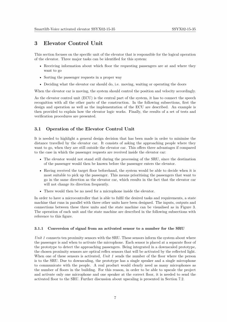
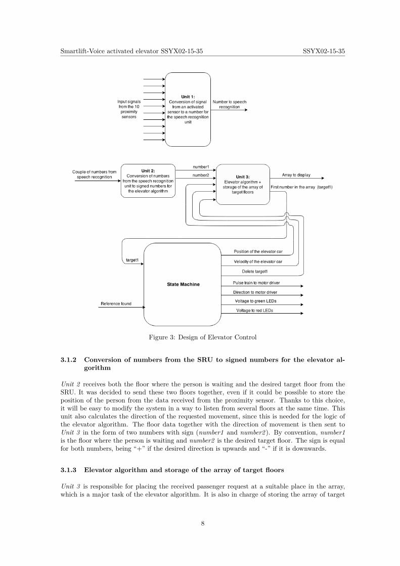
In order to have a microcontroller that is able to fulfil the desired tasks and requirements, a statemachine that runs in parallel with three other units have been designed. The inputs, outputs andconnections between these three units and the state machine can be visualised as in Figure 3.The operation of each unit and the state machine are described in the following subsections withreference to this figure.
3.1.1 Conversion of signal from an activated sensor to a number for the SRU
Unit 1 connects ten proximity sensors with the SRU. These sensors inform the system about wherethe passenger is and when to activate the microphone. Each sensor is placed at a separate floor ofthe prototype to detect the approaching passengers. Being integrated in a downscaled prototype,the chosen proximity sensors are optical reflex sensors that will be activated by the reflected light.When one of these sensors is activated, Unit 1 sends the number of the floor where the personis to the SRU. Due to downscaling, the prototype has a single speaker and a single microphoneto communicate with the people. A real product would clearly need as many microphones asthe number of floors in the building. For this reason, in order to be able to upscale the projectand activate only one microphone and one speaker at the correct floor, it is needed to send theactivated floor to the SRU. Further discussion about upscaling is presented in Section 7.2.
7
Smartlift-Voice activated elevator SSYX02-15-35 SSYX02-15-35
Figure 3: Design of Elevator Control
3.1.2 Conversion of numbers from the SRU to signed numbers for the elevator al-gorithm
Unit 2 receives both the floor where the person is waiting and the desired target floor from theSRU. It was decided to send these two floors together, even if it could be possible to store theposition of the person from the data received from the proximity sensor. Thanks to this choice,it will be easy to modify the system in a way to listen from several floors at the same time. Thisunit also calculates the direction of the requested movement, since this is needed for the logic ofthe elevator algorithm. The floor data together with the direction of movement is then sent toUnit 3 in the form of two numbers with sign (number1 and number2 ). By convention, number1is the floor where the person is waiting and number2 is the desired target floor. The sign is equalfor both numbers, being “+” if the desired direction is upwards and “-” if it is downwards.
3.1.3 Elevator algorithm and storage of the array of target floors
Unit 3 is responsible for placing the received passenger request at a suitable place in the array,which is a major task of the elevator algorithm. It is also in charge of storing the array of target
8
Smartlift-Voice activated elevator SSYX02-15-35 SSYX02-15-35
floors. In order to minimise the travel time and thereby be energy-efficient, the main strategy ofthe elevator algorithm is decided to be as follows:
Continue in the current direction as long as there are more users that want to goin the same direction, placed in floors that have not been reached yet.
In accordance with this strategy, a “+” or “-” sign is sent, to easily sort all positive floors togetherin an increasing order and all negative floors together also in an increasing order. The algorithmuses the current position (position) and velocity (velocity) as inputs from the elevator car in orderto determine if there is enough time to change the first target floor in the array, if needed.
The first target floor (target1 ) is an input for the state machine. The size of the array is ten,i.e. maximum ten target floors will be stored in the array, which is enough to demonstrate theoperation of the elevator. The first position in the array is sent to a display for the purposeof showing the operation of the elevator algorithm. The signal called delete target1 is activatedby the state machine when the first target floor in the array is reached. When it is activated,the elevator algorithm deletes the first target floor in the array and moves the remaining targetfloors one place forward. The vacant position is then filled with the number 0, because it will beinterpreted as "for the moment there are no pending requests".
3.1.4 State Machine
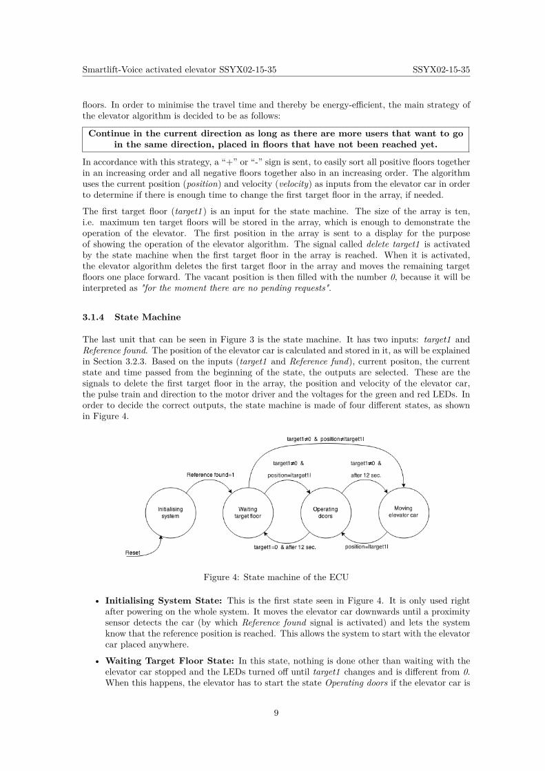
The last unit that can be seen in Figure 3 is the state machine. It has two inputs: target1 andReference found. The position of the elevator car is calculated and stored in it, as will be explainedin Section 3.2.3. Based on the inputs (target1 and Reference fund), current positon, the currentstate and time passed from the beginning of the state, the outputs are selected. These are thesignals to delete the first target floor in the array, the position and velocity of the elevator car,the pulse train and direction to the motor driver and the voltages for the green and red LEDs. Inorder to decide the correct outputs, the state machine is made of four different states, as shownin Figure 4.
Figure 4: State machine of the ECU
• Initialising System State: This is the first state seen in Figure 4. It is only used rightafter powering on the whole system. It moves the elevator car downwards until a proximitysensor detects the car (by which Reference found signal is activated) and lets the systemknow that the reference position is reached. This allows the system to start with the elevatorcar placed anywhere.
• Waiting Target Floor State: In this state, nothing is done other than waiting with theelevator car stopped and the LEDs turned off until target1 changes and is different from 0.When this happens, the elevator has to start the state Operating doors if the elevator car is
9
Smartlift-Voice activated elevator SSYX02-15-35 SSYX02-15-35
already in target1. Otherwise, if the current position is not the target floor, it has to go tostate Moving elevator car.
• Operating Doors State: Every time this state is reached, the elevator car is in the desiredtarget1. First of all, the system waits for one second in order to have some safety marginbefore opening the doors. Then, it opens the doors during 3 seconds at the floor target1(activation signal to the green LED), waits for 2 seconds and closes the doors during 3seconds (activation signal to the red LED). After this is executed, it sends a signal to deletetarget1. Then, it is checked if deleting another floor is needed (i.e same target floor). In thatcase, another activation signal is sent in delete target1, which may be needed if the elevatorcar is at the border of changing direction. In this case, the floor that was deleted just afterclosing the doors may be the same as the new target floor but with opposite sign. As thefloor has already been reached, it also has to be deleted from the array. After 12 secondsfrom the beginning of Operating doors state, the system will go to Moving elevator car stateor to Waiting target floor state, depending on whether the new target floor (target1 ) is 0 ornot, respectively.
• Moving Elevator Car State: This state includes a proportional control of position andvelocity to meet the requirements previously described. The position reference is defined asthe target floor converted into steps that the motor has to take to reach that floor. The errorto the desired position will be calculated by subtracting the current position of the elevatorcar in steps too. The details of the design of the motor control are explained in Section 3.1.5.When the target floor is reached, the state machine changes to Operating doors state.
3.1.5 Motion Control
As motivated in Sections 5.5 and 5.6, a stepper motor and the A4988 motor driver were chosen todrive the elevator car. The chosen motor driver requires only two outputs from the microcontrollerboard: a pulse train signal and a direction signal. Each rising-edge of the pulse train signal willmake the motor move one discrete step in the direction indicated by the direction signal.
The main disadvantage of using a stepper motor if compared to a servo motor is that it does nothave a feedback signal. Therefore, an external device (such as an encoder) would be required toget a feedback signal. It was decided not to use this extra device due to three main reasons:
• An extra device would introduce additional complexity to the system, which is not desirablein view of the present level of complexity on the Smartlift project.
• The mass of the elevator car and the inertia of the bobbin are insignificant to the systemdynamics, which means that the design objectives can be achieved with a standard steppermotor in the prototype.
• A simulated feedback inside the microcontroller would help realise some features of genuinefeedback control.
A simulated feedback inside the microcontroller, instead of a usual feedforward, allows for achievinga smooth stopping of the elevator car. A smooth acceleration is achieved at the beginning thanksto the system dynamics. In case there is an unexpected delay in the arrival time of the elevatorcar to a floor, caused by the system dynamics, 1.5 seconds are waited until the signal to open thedoors is active.
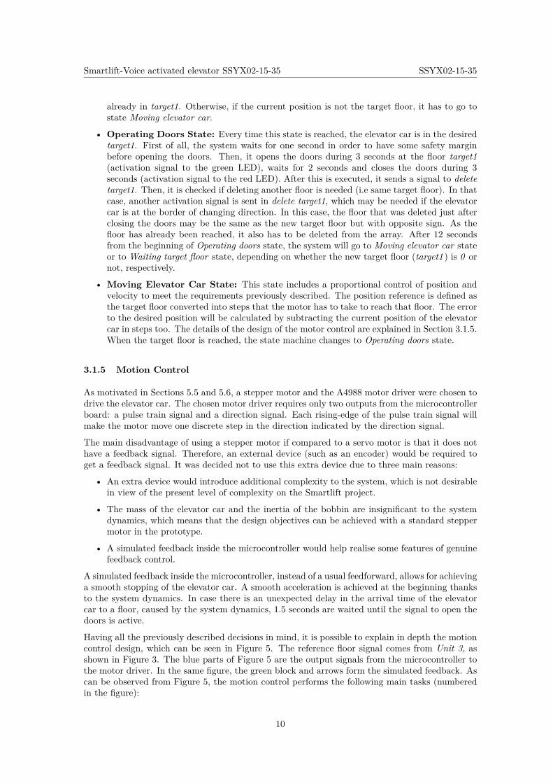
Having all the previously described decisions in mind, it is possible to explain in depth the motioncontrol design, which can be seen in Figure 5. The reference floor signal comes from Unit 3, asshown in Figure 3. The blue parts of Figure 5 are the output signals from the microcontroller tothe motor driver. In the same figure, the green block and arrows form the simulated feedback. Ascan be observed from Figure 5, the motion control performs the following main tasks (numberedin the figure):
10
Smartlift-Voice activated elevator SSYX02-15-35 SSYX02-15-35
Figure 5: Motion control design
1. The reference position in floors is converted into the amount of motor steps needed to reachthe reference floor.
2. The error in steps related to the reference is obtained by subtracting the simulated signal ofthe current position in steps from the reference position.
3. A proportional controller calculates the frequency of a pulse train signal. As can be seenin Figure 11, the integral branch of the controller is not needed because there would be noposition error in steady state. The derivative branch of the controller has no effect on theperformance, since the feedback signal is not real but simulated.
4. The maximum desired speed is limited through saturation, which corresponds to 5cm/s. Asexplained in Section 5, each floor of the prototype is 15cm high, which implies that it takes3 seconds to reach each floor at maximum speed. In the same section, it is explained that100 motor steps correspond to one floor. Therefore, the frequency of the train of pulses hasto be
100steps/3s = 33.3Hz.
This is why the salutation limits are set to +33.3 and -33.3, where the negative valuescorrespond to a pulse train that moves the elevator car downwards.
5. The period of the desired pulse train is calculated in order to use the Programmable pulsegenerator, developed by Dustin, permitted to use 3. This pulse train is an output from themicrocontroller to the motor driver.
6. The direction of the movement is calculated from the sign of the frequency of pulses, whichcorresponds to the sign of the error previously calculated. It is also an output from themicrocontroller to the motor driver.
7. In order to simulate a feedback of the current position of the elevator, the rising-edges ofthe pulse train signal are counted, since each of them corresponds to a step in the motor. Ifthe direction is upwards, the counted rising-edges are added to the current position in steps;otherwise they are subtracted. Thanks to the calculation and storage of the position in stepsof the elevator car, we can use the designed proportional controller.
It has to be highlighted that the action of the proportional controller only affects the movementduring the last steps before reaching the desired floor. In order to stop in a smooth way, thevalue of the proportional gain was experimentally adjusted to 2. Further explanation about theimplementation of the motor control is provided in Section 3.2.4.
3Copyright (C) 2008, Dustin. All rights reserved. Permited use.http://www.mathworks.com/matlabcentral/fileexchange/19600-simulink-programmable-pulse-generator/content//ProgrammablePulseGenerator.mdl
11
Smartlift-Voice activated elevator SSYX02-15-35 SSYX02-15-35
3.2 Implementation
The algorithms that constitute all the subunits of the ECU are implemented in MATLAB andSimulink. The state machine uses a very powerful tool of Simulink called StateFlow, which permitsto use Simulink blocks and MATLAB functions inside a state. For instance, this allows theimplementation of the proportional controller in an easy way. Simulink and MATLAB were chosenfor algorithm implementation since they have support packages for ArduinoTM Mega ADK board,which allows the development of complex systems .
For the case of implementation using the SRU, a general picture of the top-level of the Simulinkprogram is shown in Appendices C and D. For the case of using buttons inputs instead, the top-level Simulink model of the Unit1, Unit2 and Unit3 is shown in Appendix E. In the followingsections, the implementation of the different parts of the ECU is explained in some detail.
3.2.1 Implementation of Unit 1 and Unit 2
Both units are triggered rising-edge subsystems in Simulink, which contain MATLAB functionsthat are triggered by their own input signals. In this manner, the MATLAB functions will onlybe executed when there is a new input.
For the case of implementation with SRU, Unit 1 converts the activated sensor signal from a floorinto the corresponding four-bit number of the floor, which is sent to SRU. Unit 2 receives numbersa and c in binary representation from SRU and converts them into natural numbers. Then, thefirst number a (entering floor) and the second number c (target floor) are subtracted. Dependingon the sign of this result, a "+" or a "-" sign will be added to the calculated natural numbers if thepassenger wants to go upwards or downwards, respectively. This integer numbers are outputs ofUnit 2, being number1 the corresponding integer number to the entering floor and number2 thecorresponding integer number to the target floor. The MATLAB codes of the functions of Unit 1and Unit 2 can be seen in Appendix G and H respectively.
In the case of button input signals instead of the SRU, Unit 1 converts the activated sensor signalfrom a floor into the corresponding natural number of the floor. This number is stored in amemory block. Unit 2 receives the number stored in the block memory (a) and the signals fromthe buttons. Depending on the button that is pressed, the natural number c is calculated. Asin the previous case, number a (entering floor) and number c (target floor) are subtracted, anddepending on the sign of this result the corresponding sign is added to the natural numbers. Theoutputs are also numeber1 and number2. For this case of input through buttons, the MATLABcodes of the functions of Unit 1 and Unit 2 can be seen in Appendix I and J respectively.
3.2.2 Implementation of Unit 3
Unit 3 has two main parts: the elevator algorithm that sorts the requested floors and the storageof the array of target floors. The elevator algorithm is implemented as a MATLAB function thatis inside a triggered subsystem just as Unit 1 and Unit 2. The trigger signals are number1 anddelete target1, since the array of target floors has to be refreshed each time the signals changevalues. Number2 is not a trigger signal since Unit 2 ensures that there will always be a rising-edgein number1 and in number2 at the same time. The storage of the array of target floors is donethrough Simulink blocks called Data Store Memory, Data Store Write and Data Store Read.
The operation of the elevator algorithm is performed by the MATLAB code in Appendix K andcan be explained as follows:
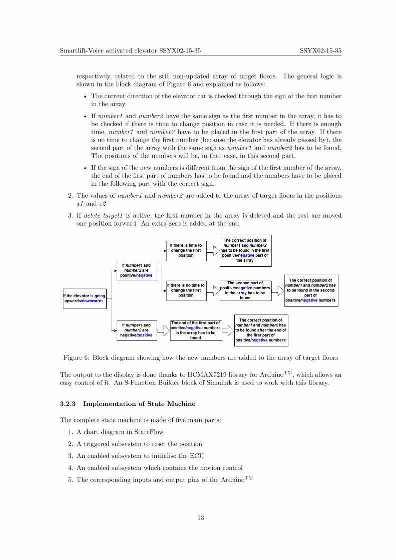
1. If number1 and number2 are different from zero, they have to be added to the array. Inthat case, if there are at least two empty positions in the array, suitable places are searchedfor both numbers. The variables x1 and x2 contain the positions of number1 and number2
12
Smartlift-Voice activated elevator SSYX02-15-35 SSYX02-15-35
respectively, related to the still non-updated array of target floors. The general logic isshown in the block diagram of Figure 6 and explained as follows:
• The current direction of the elevator car is checked through the sign of the first numberin the array.
• If number1 and number2 have the same sign as the first number in the array, it has tobe checked if there is time to change position in case it is needed. If there is enoughtime, number1 and number2 have to be placed in the first part of the array. If thereis no time to change the first number (because the elevator has already passed by), thesecond part of the array with the same sign as number1 and number2 has to be found.The positions of the numbers will be, in that case, in this second part.
• If the sign of the new numbers is different from the sign of the first number of the array,the end of the first part of numbers has to be found and the numbers have to be placedin the following part with the correct sign.
2. The values of number1 and number2 are added to the array of target floors in the positionsx1 and x2
3. If delete target1 is active, the first number in the array is deleted and the rest are movedone position forward. An extra zero is added at the end.
Figure 6: Block diagram showing how the new numbers are added to the array of target floors
The output to the display is done thanks to HCMAX7219 library for ArduinoTM, which allows aneasy control of it. An S-Function Builder block of Simulink is used to work with this library.
3.2.3 Implementation of State Machine
The complete state machine is made of five main parts:
1. A chart diagram in StateFlow
2. A triggered subsystem to reset the position
3. An enabled subsystem to initialise the ECU
4. An enabled subsystem which contains the motion control
5. The corresponding inputs and output pins of the ArduinoTM
13
Smartlift-Voice activated elevator SSYX02-15-35 SSYX02-15-35
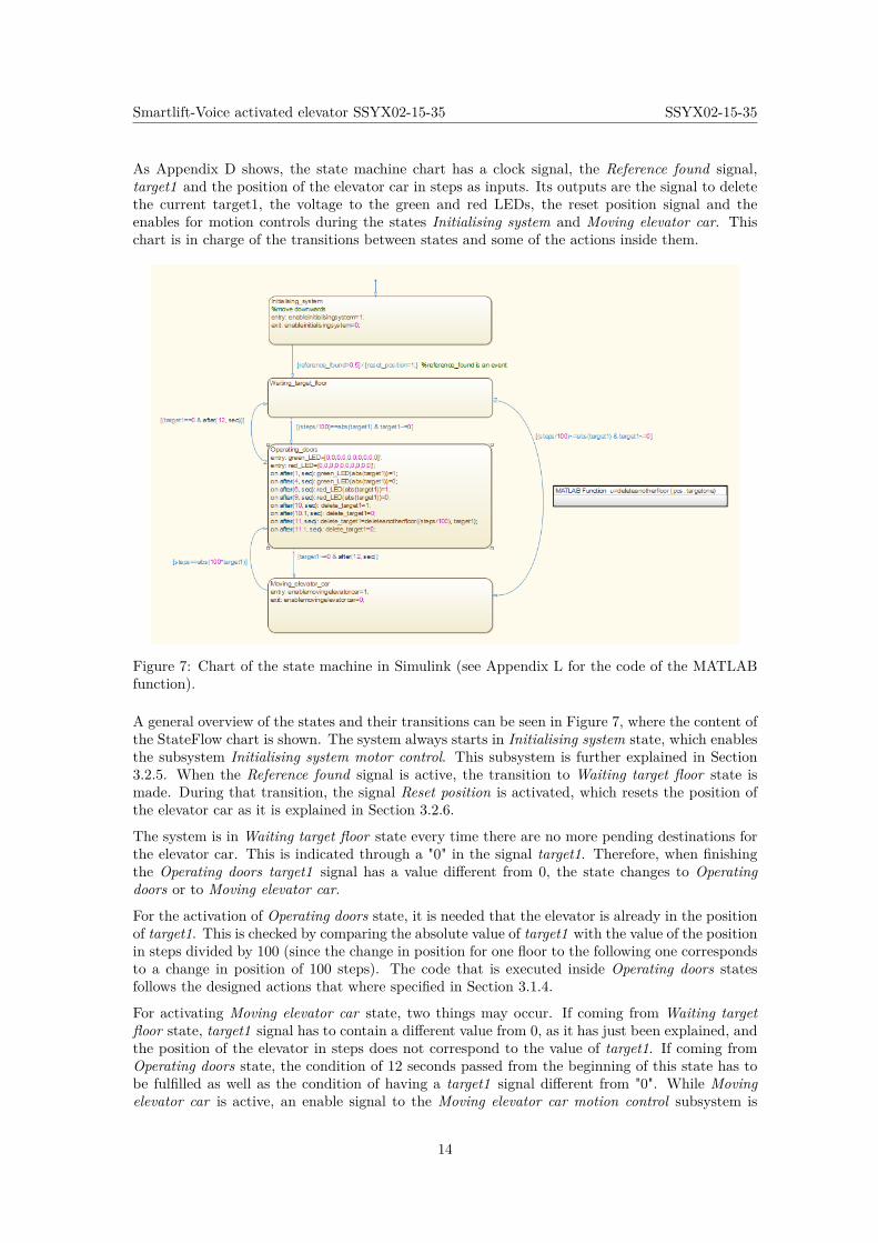
As Appendix D shows, the state machine chart has a clock signal, the Reference found signal,target1 and the position of the elevator car in steps as inputs. Its outputs are the signal to deletethe current target1, the voltage to the green and red LEDs, the reset position signal and theenables for motion controls during the states Initialising system and Moving elevator car. Thischart is in charge of the transitions between states and some of the actions inside them.
Figure 7: Chart of the state machine in Simulink (see Appendix L for the code of the MATLABfunction).
A general overview of the states and their transitions can be seen in Figure 7, where the content ofthe StateFlow chart is shown. The system always starts in Initialising system state, which enablesthe subsystem Initialising system motor control. This subsystem is further explained in Section3.2.5. When the Reference found signal is active, the transition to Waiting target floor state ismade. During that transition, the signal Reset position is activated, which resets the position ofthe elevator car as it is explained in Section 3.2.6.
The system is in Waiting target floor state every time there are no more pending destinations forthe elevator car. This is indicated through a "0" in the signal target1. Therefore, when finishingthe Operating doors target1 signal has a value different from 0, the state changes to Operatingdoors or to Moving elevator car.
For the activation of Operating doors state, it is needed that the elevator is already in the positionof target1. This is checked by comparing the absolute value of target1 with the value of the positionin steps divided by 100 (since the change in position for one floor to the following one correspondsto a change in position of 100 steps). The code that is executed inside Operating doors statesfollows the designed actions that where specified in Section 3.1.4.
For activating Moving elevator car state, two things may occur. If coming from Waiting targetfloor state, target1 signal has to contain a different value from 0, as it has just been explained, andthe position of the elevator in steps does not correspond to the value of target1. If coming fromOperating doors state, the condition of 12 seconds passed from the beginning of this state has tobe fulfilled as well as the condition of having a target1 signal different from "0". While Movingelevator car is active, an enable signal to the Moving elevator car motion control subsystem is
14
Smartlift-Voice activated elevator SSYX02-15-35 SSYX02-15-35
sent. A further explanation of this subsystem is explained in Section 3.2.5. When the target flooris reached, Operating doors state will be active, since the position of the elevator car in steps willbe equal to the absolute value of 100 times the number contained in target1.
3.2.4 Implementation of Motion Control
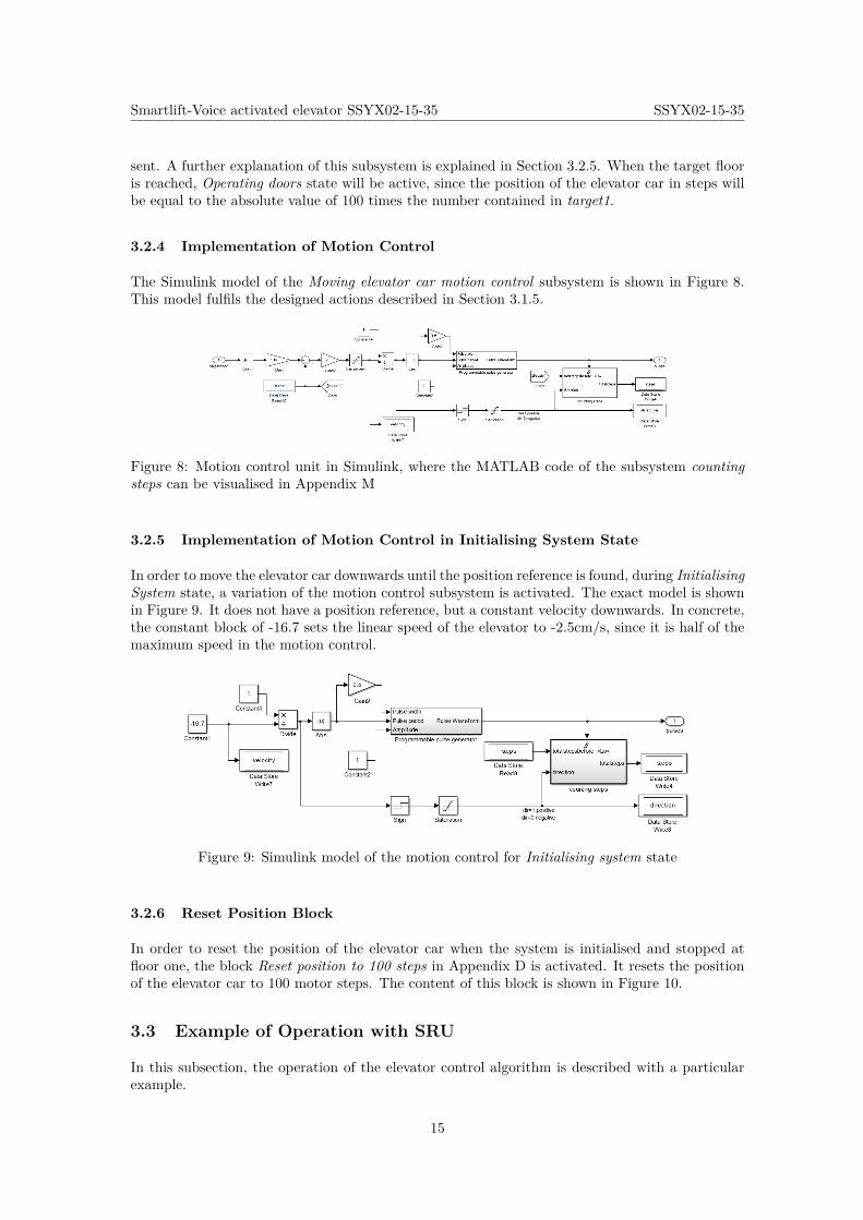
The Simulink model of the Moving elevator car motion control subsystem is shown in Figure 8.This model fulfils the designed actions described in Section 3.1.5.
Figure 8: Motion control unit in Simulink, where the MATLAB code of the subsystem countingsteps can be visualised in Appendix M
3.2.5 Implementation of Motion Control in Initialising System State
In order to move the elevator car downwards until the position reference is found, during InitialisingSystem state, a variation of the motion control subsystem is activated. The exact model is shownin Figure 9. It does not have a position reference, but a constant velocity downwards. In concrete,the constant block of -16.7 sets the linear speed of the elevator to -2.5cm/s, since it is half of themaximum speed in the motion control.
Figure 9: Simulink model of the motion control for Initialising system state
3.2.6 Reset Position Block
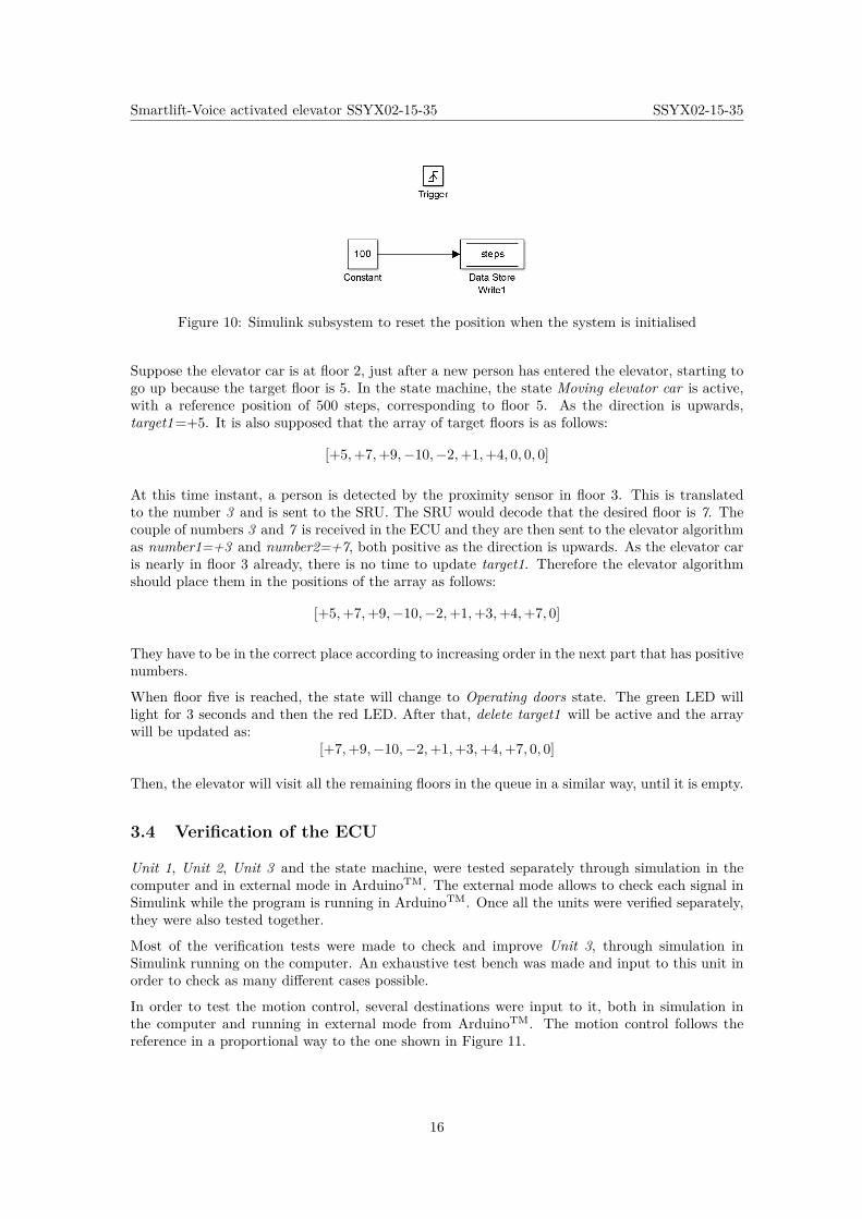
In order to reset the position of the elevator car when the system is initialised and stopped atfloor one, the block Reset position to 100 steps in Appendix D is activated. It resets the positionof the elevator car to 100 motor steps. The content of this block is shown in Figure 10.
3.3 Example of Operation with SRU
In this subsection, the operation of the elevator control algorithm is described with a particularexample.
15
Smartlift-Voice activated elevator SSYX02-15-35 SSYX02-15-35
Figure 10: Simulink subsystem to reset the position when the system is initialised
Suppose the elevator car is at floor 2, just after a new person has entered the elevator, starting togo up because the target floor is 5. In the state machine, the state Moving elevator car is active,with a reference position of 500 steps, corresponding to floor 5. As the direction is upwards,target1=+5. It is also supposed that the array of target floors is as follows:
[+5,+7,+9,−10,−2,+1,+4, 0, 0, 0]
At this time instant, a person is detected by the proximity sensor in floor 3. This is translatedto the number 3 and is sent to the SRU. The SRU would decode that the desired floor is 7. Thecouple of numbers 3 and 7 is received in the ECU and they are then sent to the elevator algorithmas number1=+3 and number2=+7, both positive as the direction is upwards. As the elevator caris nearly in floor 3 already, there is no time to update target1. Therefore the elevator algorithmshould place them in the positions of the array as follows:
[+5,+7,+9,−10,−2,+1,+3,+4,+7, 0]
They have to be in the correct place according to increasing order in the next part that has positivenumbers.
When floor five is reached, the state will change to Operating doors state. The green LED willlight for 3 seconds and then the red LED. After that, delete target1 will be active and the arraywill be updated as:
[+7,+9,−10,−2,+1,+3,+4,+7, 0, 0]
Then, the elevator will visit all the remaining floors in the queue in a similar way, until it is empty.
3.4 Verification of the ECU
Unit 1, Unit 2, Unit 3 and the state machine, were tested separately through simulation in thecomputer and in external mode in ArduinoTM. The external mode allows to check each signal inSimulink while the program is running in ArduinoTM. Once all the units were verified separately,they were also tested together.
Most of the verification tests were made to check and improve Unit 3, through simulation inSimulink running on the computer. An exhaustive test bench was made and input to this unit inorder to check as many different cases possible.
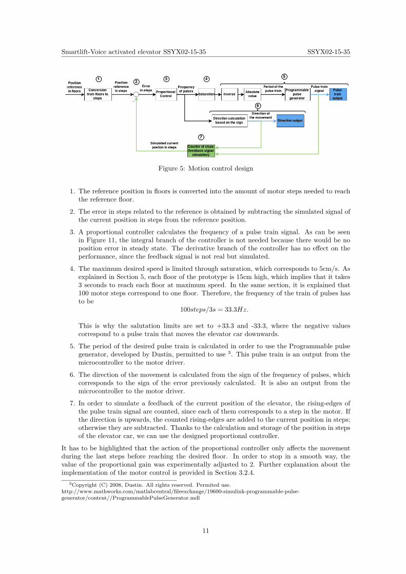
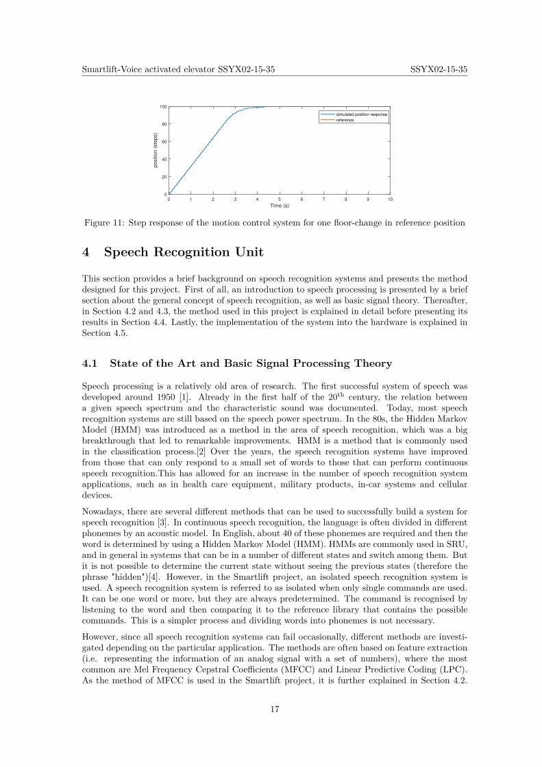
In order to test the motion control, several destinations were input to it, both in simulation inthe computer and running in external mode from ArduinoTM. The motion control follows thereference in a proportional way to the one shown in Figure 11.
16
Smartlift-Voice activated elevator SSYX02-15-35 SSYX02-15-35
Time (s)
0 1 2 3 4 5 6 7 8 9 10
positio
n (
ste
ps)
0
20
40
60
80
100
simulated position response
reference
Figure 11: Step response of the motion control system for one floor-change in reference position
4 Speech Recognition Unit
This section provides a brief background on speech recognition systems and presents the methoddesigned for this project. First of all, an introduction to speech processing is presented by a briefsection about the general concept of speech recognition, as well as basic signal theory. Thereafter,in Section 4.2 and 4.3, the method used in this project is explained in detail before presenting itsresults in Section 4.4. Lastly, the implementation of the system into the hardware is explained inSection 4.5.
4.1 State of the Art and Basic Signal Processing Theory
Speech processing is a relatively old area of research. The first successful system of speech wasdeveloped around 1950 [1]. Already in the first half of the 20th century, the relation betweena given speech spectrum and the characteristic sound was documented. Today, most speechrecognition systems are still based on the speech power spectrum. In the 80s, the Hidden MarkovModel (HMM) was introduced as a method in the area of speech recognition, which was a bigbreakthrough that led to remarkable improvements. HMM is a method that is commonly usedin the classification process.[2] Over the years, the speech recognition systems have improvedfrom those that can only respond to a small set of words to those that can perform continuousspeech recognition.This has allowed for an increase in the number of speech recognition systemapplications, such as in health care equipment, military products, in-car systems and cellulardevices.
Nowadays, there are several different methods that can be used to successfully build a system forspeech recognition [3]. In continuous speech recognition, the language is often divided in differentphonemes by an acoustic model. In English, about 40 of these phonemes are required and then theword is determined by using a Hidden Markov Model (HMM). HMMs are commonly used in SRU,and in general in systems that can be in a number of different states and switch among them. Butit is not possible to determine the current state without seeing the previous states (therefore thephrase "hidden")[4]. However, in the Smartlift project, an isolated speech recognition system isused. A speech recognition system is referred to as isolated when only single commands are used.It can be one word or more, but they are always predetermined. The command is recognised bylistening to the word and then comparing it to the reference library that contains the possiblecommands. This is a simpler process and dividing words into phonemes is not necessary.
However, since all speech recognition systems can fail occasionally, different methods are investi-gated depending on the particular application. The methods are often based on feature extraction(i.e. representing the information of an analog signal with a set of numbers), where the mostcommon are Mel Frequency Cepstral Coefficients (MFCC) and Linear Predictive Coding (LPC).As the method of MFCC is used in the Smartlift project, it is further explained in Section 4.2.
17
Smartlift-Voice activated elevator SSYX02-15-35 SSYX02-15-35
Once the features are extracted, a method of classification is needed. Frequently the methods usedare either HMM or Dynamic Time Warping (DTW).
Some of the challenges remaining in the Smartlift project after the SRU has been limited is:
• Additive noise to the source signal
• Speech accents
• Different frequency levels between women and men
• Similarity between phrases that are used
In the signal processing for speech recognition systems, Fourier Transform has a central part;therefore it will be briefly described here. Fourier Transform is a function that is used to transforma signal from the time domain to frequency domain. The variability in the time domain whenhandling speech is high and it is known that different tones correspond to different levels of energyin the frequency domain. Therefore applying FT to get the magnitude frequency response will bevery useful when handling with speech recognition. However this is not enough and the signal hasto be processed further for a successful classification process.
4.2 Isolated Speech Recognition Algorithm
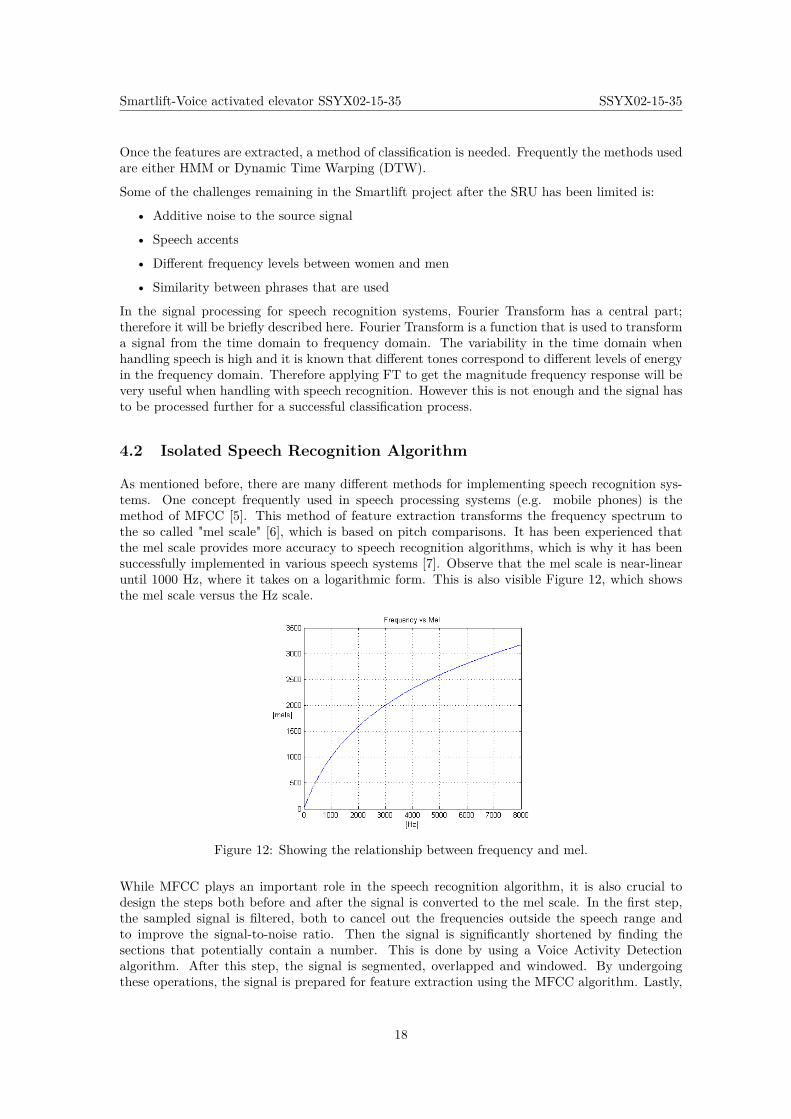
As mentioned before, there are many different methods for implementing speech recognition sys-tems. One concept frequently used in speech processing systems (e.g. mobile phones) is themethod of MFCC [5]. This method of feature extraction transforms the frequency spectrum tothe so called "mel scale" [6], which is based on pitch comparisons. It has been experienced thatthe mel scale provides more accuracy to speech recognition algorithms, which is why it has beensuccessfully implemented in various speech systems [7]. Observe that the mel scale is near-linearuntil 1000 Hz, where it takes on a logarithmic form. This is also visible Figure 12, which showsthe mel scale versus the Hz scale.
Figure 12: Showing the relationship between frequency and mel.
While MFCC plays an important role in the speech recognition algorithm, it is also crucial todesign the steps both before and after the signal is converted to the mel scale. In the first step,the sampled signal is filtered, both to cancel out the frequencies outside the speech range andto improve the signal-to-noise ratio. Then the signal is significantly shortened by finding thesections that potentially contain a number. This is done by using a Voice Activity Detectionalgorithm. After this step, the signal is segmented, overlapped and windowed. By undergoingthese operations, the signal is prepared for feature extraction using the MFCC algorithm. Lastly,
18
Smartlift-Voice activated elevator SSYX02-15-35 SSYX02-15-35
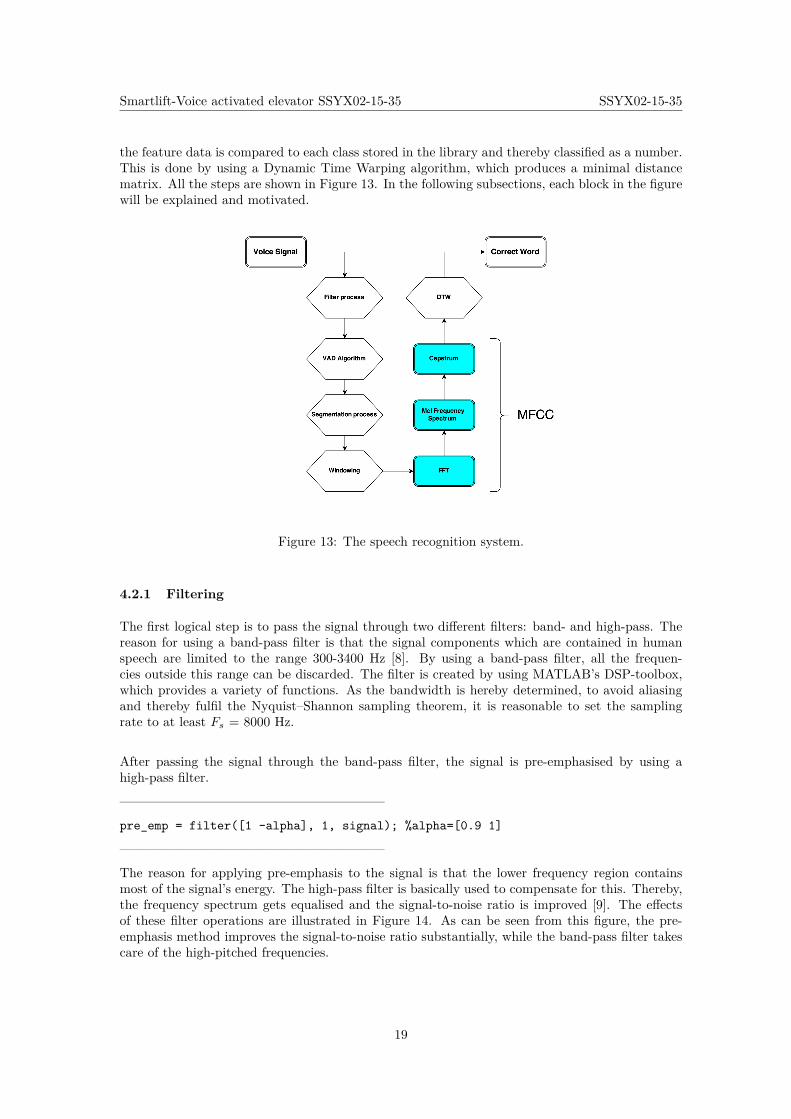
the feature data is compared to each class stored in the library and thereby classified as a number.This is done by using a Dynamic Time Warping algorithm, which produces a minimal distancematrix. All the steps are shown in Figure 13. In the following subsections, each block in the figurewill be explained and motivated.
Figure 13: The speech recognition system.
4.2.1 Filtering
The first logical step is to pass the signal through two different filters: band- and high-pass. Thereason for using a band-pass filter is that the signal components which are contained in humanspeech are limited to the range 300-3400 Hz [8]. By using a band-pass filter, all the frequen-cies outside this range can be discarded. The filter is created by using MATLAB’s DSP-toolbox,which provides a variety of functions. As the bandwidth is hereby determined, to avoid aliasingand thereby fulfil the Nyquist–Shannon sampling theorem, it is reasonable to set the samplingrate to at least Fs = 8000 Hz.
After passing the signal through the band-pass filter, the signal is pre-emphasised by using ahigh-pass filter.
————————————————————
pre_emp = filter([1 -alpha], 1, signal); %alpha=[0.9 1]
————————————————————
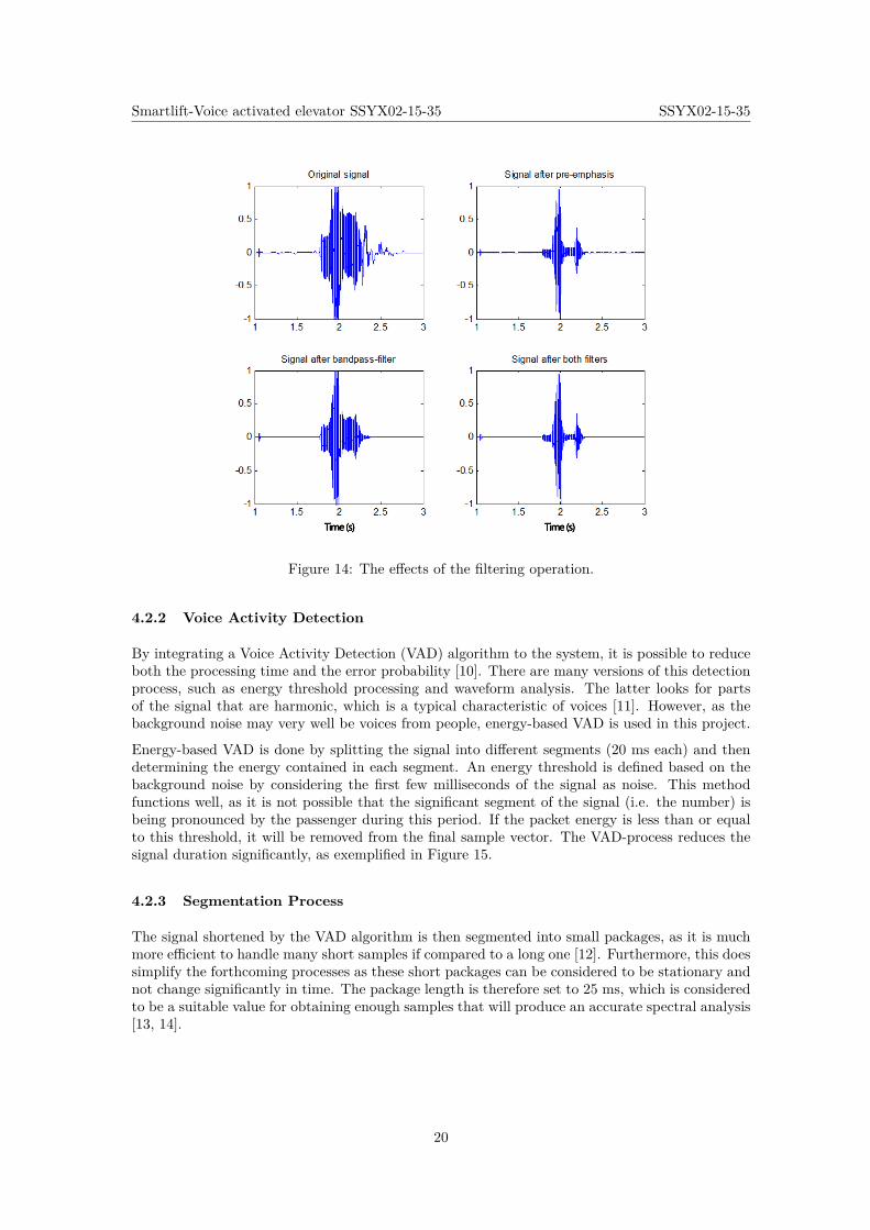
The reason for applying pre-emphasis to the signal is that the lower frequency region containsmost of the signal’s energy. The high-pass filter is basically used to compensate for this. Thereby,the frequency spectrum gets equalised and the signal-to-noise ratio is improved [9]. The effectsof these filter operations are illustrated in Figure 14. As can be seen from this figure, the pre-emphasis method improves the signal-to-noise ratio substantially, while the band-pass filter takescare of the high-pitched frequencies.
19
Smartlift-Voice activated elevator SSYX02-15-35 SSYX02-15-35
Figure 14: The effects of the filtering operation.
4.2.2 Voice Activity Detection
By integrating a Voice Activity Detection (VAD) algorithm to the system, it is possible to reduceboth the processing time and the error probability [10]. There are many versions of this detectionprocess, such as energy threshold processing and waveform analysis. The latter looks for partsof the signal that are harmonic, which is a typical characteristic of voices [11]. However, as thebackground noise may very well be voices from people, energy-based VAD is used in this project.
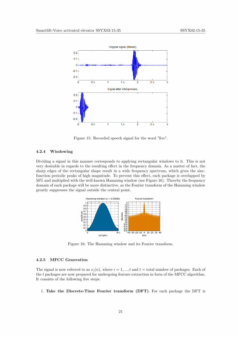
Energy-based VAD is done by splitting the signal into different segments (20 ms each) and thendetermining the energy contained in each segment. An energy threshold is defined based on thebackground noise by considering the first few milliseconds of the signal as noise. This methodfunctions well, as it is not possible that the significant segment of the signal (i.e. the number) isbeing pronounced by the passenger during this period. If the packet energy is less than or equalto this threshold, it will be removed from the final sample vector. The VAD-process reduces thesignal duration significantly, as exemplified in Figure 15.
4.2.3 Segmentation Process
The signal shortened by the VAD algorithm is then segmented into small packages, as it is muchmore efficient to handle many short samples if compared to a long one [12]. Furthermore, this doessimplify the forthcoming processes as these short packages can be considered to be stationary andnot change significantly in time. The package length is therefore set to 25 ms, which is consideredto be a suitable value for obtaining enough samples that will produce an accurate spectral analysis[13, 14].
20
Smartlift-Voice activated elevator SSYX02-15-35 SSYX02-15-35
Figure 15: Recorded speech signal for the word "five".
4.2.4 Windowing
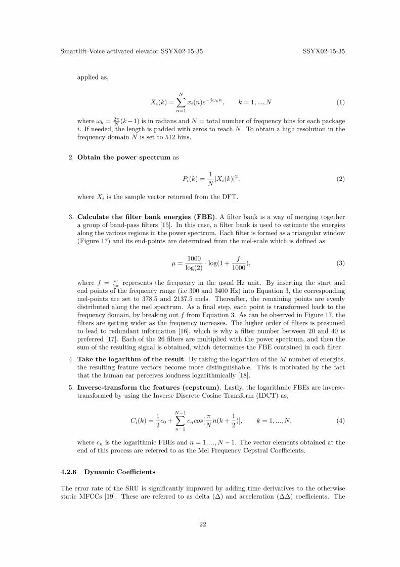
Dividing a signal in this manner corresponds to applying rectangular windows to it. This is notvery desirable in regards to the resulting effect in the frequency domain. As a matter of fact, thesharp edges of the rectangular shape result in a wide frequency spectrum, which gives the sinc-function periodic peaks of high magnitude. To prevent this effect, each package is overlapped by50% and multiplied with the well-known Hamming window (see Figure 16). Thereby the frequencydomain of each package will be more distinctive, as the Fourier transform of the Hamming windowgreatly suppresses the signal outside the central point.
Figure 16: The Hamming window and its Fourier transform.
4.2.5 MFCC Generation
The signal is now referred to as xi(n), where i = 1, ..., t and t = total number of packages. Each ofthe t packages are now prepared for undergoing feature extraction in form of the MFCC algorithm.It consists of the following five steps:
1. Take the Discrete-Time Fourier transform (DFT). For each package the DFT is
21
Smartlift-Voice activated elevator SSYX02-15-35 SSYX02-15-35
applied as,
Xi(k) =N∑n=1
xi(n)e−jωkn, k = 1, ..., N (1)
where ωk = 2πN (k−1) is in radians and N = total number of frequency bins for each package
i. If needed, the length is padded with zeros to reach N . To obtain a high resolution in thefrequency domain N is set to 512 bins.
2. Obtain the power spectrum as
Pi(k) = 1N|Xi(k)|2, (2)
where Xi is the sample vector returned from the DFT.
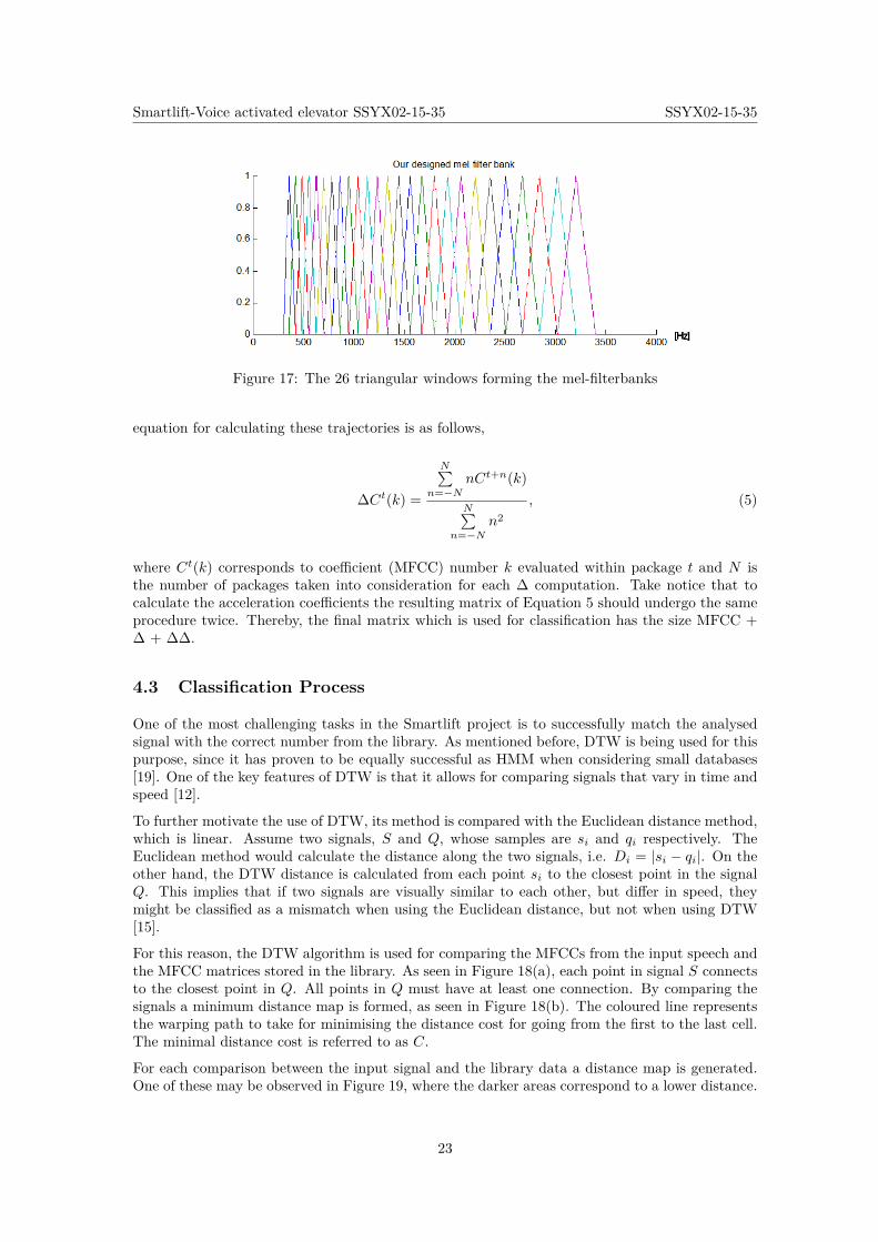
3. Calculate the filter bank energies (FBE). A filter bank is a way of merging togethera group of band-pass filters [15]. In this case, a filter bank is used to estimate the energiesalong the various regions in the power spectrum. Each filter is formed as a triangular window(Figure 17) and its end-points are determined from the mel-scale which is defined as
µ = 1000log(2) · log(1 + f
1000), (3)
where f = ω2π represents the frequency in the usual Hz unit. By inserting the start and
end points of the frequency range (i.e 300 and 3400 Hz) into Equation 3, the correspondingmel-points are set to 378.5 and 2137.5 mels. Thereafter, the remaining points are evenlydistributed along the mel spectrum. As a final step, each point is transformed back to thefrequency domain, by breaking out f from Equation 3. As can be observed in Figure 17, thefilters are getting wider as the frequency increases. The higher order of filters is presumedto lead to redundant information [16], which is why a filter number between 20 and 40 ispreferred [17]. Each of the 26 filters are multiplied with the power spectrum, and then thesum of the resulting signal is obtained, which determines the FBE contained in each filter.
4. Take the logarithm of the result. By taking the logarithm of the M number of energies,the resulting feature vectors become more distinguishable. This is motivated by the factthat the human ear perceives loudness logarithmically [18].
5. Inverse-transform the features (cepstrum). Lastly, the logarithmic FBEs are inverse-transformed by using the Inverse Discrete Cosine Transform (IDCT) as,
Ci(k) = 12c0 +
N−1∑n=1
cncos[π
Nn(k + 1
2)], k = 1, ..., N, (4)
where cn is the logarithmic FBEs and n = 1, ..., N − 1. The vector elements obtained at theend of this process are referred to as the Mel Frequency Cepstral Coefficients.
4.2.6 Dynamic Coefficients
The error rate of the SRU is significantly improved by adding time derivatives to the otherwisestatic MFCCs [19]. These are referred to as delta (∆) and acceleration (∆∆) coefficients. The
22
Smartlift-Voice activated elevator SSYX02-15-35 SSYX02-15-35
Figure 17: The 26 triangular windows forming the mel-filterbanks
equation for calculating these trajectories is as follows,
∆Ct(k) =
N∑n=−N
nCt+n(k)
N∑n=−N
n2, (5)
where Ct(k) corresponds to coefficient (MFCC) number k evaluated within package t and N isthe number of packages taken into consideration for each ∆ computation. Take notice that tocalculate the acceleration coefficients the resulting matrix of Equation 5 should undergo the sameprocedure twice. Thereby, the final matrix which is used for classification has the size MFCC +∆ + ∆∆.
4.3 Classification Process
One of the most challenging tasks in the Smartlift project is to successfully match the analysedsignal with the correct number from the library. As mentioned before, DTW is being used for thispurpose, since it has proven to be equally successful as HMM when considering small databases[19]. One of the key features of DTW is that it allows for comparing signals that vary in time andspeed [12].
To further motivate the use of DTW, its method is compared with the Euclidean distance method,which is linear. Assume two signals, S and Q, whose samples are si and qi respectively. TheEuclidean method would calculate the distance along the two signals, i.e. Di = |si − qi|. On theother hand, the DTW distance is calculated from each point si to the closest point in the signalQ. This implies that if two signals are visually similar to each other, but differ in speed, theymight be classified as a mismatch when using the Euclidean distance, but not when using DTW[15].
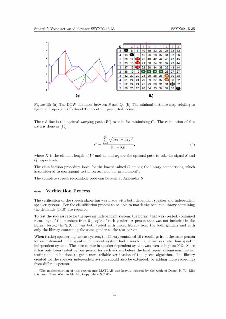
For this reason, the DTW algorithm is used for comparing the MFCCs from the input speech andthe MFCC matrices stored in the library. As seen in Figure 18(a), each point in signal S connectsto the closest point in Q. All points in Q must have at least one connection. By comparing thesignals a minimum distance map is formed, as seen in Figure 18(b). The coloured line representsthe warping path to take for minimising the distance cost for going from the first to the last cell.The minimal distance cost is referred to as C.
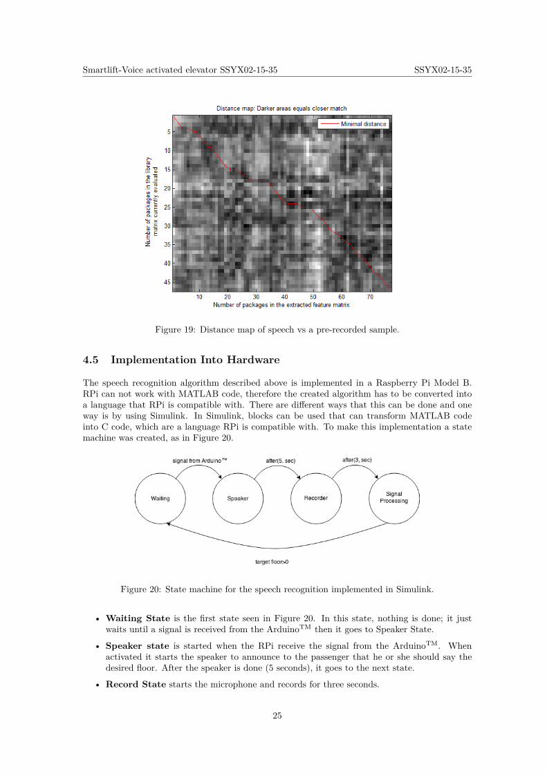
For each comparison between the input signal and the library data a distance map is generated.One of these may be observed in Figure 19, where the darker areas correspond to a lower distance.
23
Smartlift-Voice activated elevator SSYX02-15-35 SSYX02-15-35
Figure 18: (a) The DTW distances between S and Q. (b) The minimal distance map relating tofigure a. Copyright (C) Javid Taheri et al., permitted to use.
The red line is the optimal warping path (W ) to take for minimising C. The calculation of thispath is done as [15],
C =
K∑k=1
√(wki − wkj)2
|S|+ |Q| , (6)
where K is the element length of W and wi and wj are the optimal path to take for signal S andQ respectively.
The classification procedure looks for the lowest valued C among the library comparisons, whichis considered to correspond to the correct number pronounced4.
The complete speech recognition code can be seen at Appendix N.
4.4 Verification Process
The verification of the speech algorithm was made with both dependent speaker and independentspeaker systems. For the classification process to be able to match the results a library containingthe demands (1-10) are required.
To test the success rate for the speaker independent system, the library that was created, containedrecordings of the numbers from 5 people of each gender. A person that was not included in thelibrary tested the SRU, it was both tested with mixed library from the both genders and withonly the library containing the same gender as the test person.
When testing speaker dependent system, the library contained 10 recordings from the same personfor each demand. The speaker dependent system had a much higher success rate than speakerindependent system. The success rate in speaker dependent system was even so high as 90%. Sinceit has only been tested by one person for each system before the final report submission, furthertesting should be done to get a more reliable verification of the speech algorithm. The librarycreated for the speaker independent system should also be extended, by adding more recordingsfrom different persons.
4The implementation of this section into MATLAB was heavily inspired by the work of Daniel P. W. Ellis(Dynamic Time Warp in Matlab, Copyright (C) 2003).
24
Smartlift-Voice activated elevator SSYX02-15-35 SSYX02-15-35
Figure 19: Distance map of speech vs a pre-recorded sample.
4.5 Implementation Into Hardware
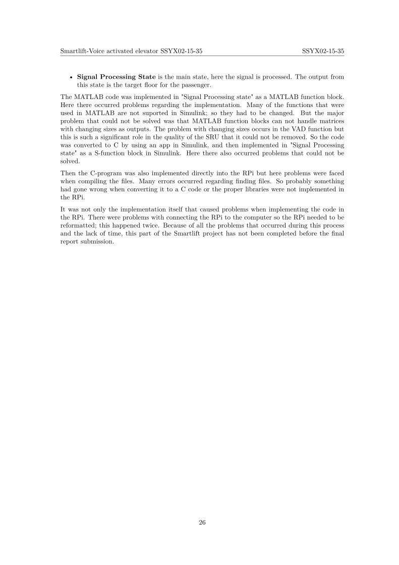
The speech recognition algorithm described above is implemented in a Raspberry Pi Model B.RPi can not work with MATLAB code, therefore the created algorithm has to be converted intoa language that RPi is compatible with. There are different ways that this can be done and oneway is by using Simulink. In Simulink, blocks can be used that can transform MATLAB codeinto C code, which are a language RPi is compatible with. To make this implementation a statemachine was created, as in Figure 20.
Figure 20: State machine for the speech recognition implemented in Simulink.
• Waiting State is the first state seen in Figure 20. In this state, nothing is done; it justwaits until a signal is received from the ArduinoTM then it goes to Speaker State.
• Speaker state is started when the RPi receive the signal from the ArduinoTM. Whenactivated it starts the speaker to announce to the passenger that he or she should say thedesired floor. After the speaker is done (5 seconds), it goes to the next state.
• Record State starts the microphone and records for three seconds.
25
Smartlift-Voice activated elevator SSYX02-15-35 SSYX02-15-35
• Signal Processing State is the main state, here the signal is processed. The output fromthis state is the target floor for the passenger.
The MATLAB code was implemented in "Signal Processing state" as a MATLAB function block.Here there occurred problems regarding the implementation. Many of the functions that wereused in MATLAB are not suported in Simulink; so they had to be changed. But the majorproblem that could not be solved was that MATLAB function blocks can not handle matriceswith changing sizes as outputs. The problem with changing sizes occurs in the VAD function butthis is such a significant role in the quality of the SRU that it could not be removed. So the codewas converted to C by using an app in Simulink, and then implemented in "Signal Processingstate" as a S-function block in Simulink. Here there also occurred problems that could not besolved.
Then the C-program was also implemented directly into the RPi but here problems were facedwhen compiling the files. Many errors occurred regarding finding files. So probably somethinghad gone wrong when converting it to a C code or the proper libraries were not implemented inthe RPi.
It was not only the implementation itself that caused problems when implementing the code inthe RPi. There were problems with connecting the RPi to the computer so the RPi needed to bereformatted; this happened twice. Because of all the problems that occurred during this processand the lack of time, this part of the Smartlift project has not been completed before the finalreport submission.
26
Smartlift-Voice activated elevator SSYX02-15-35 SSYX02-15-35
5 Physical Construction and System Components
In order to demonstrate the performance of the speech recognition and the elevator control, adownscaled prototype of an elevator has been built. In this section, the construction of theprototype and the applied components are presented.
5.1 Construction of Prototype
The construction needs to have enough floors to fully demonstrate the elevator algorithm and thespeech recognition. It also has to be transportable. To meet the requirements, the elevator carwas to be positioned stably and precisely by a motor, with an accuracy of 0.5 cm. The elevator carhas to move with a maximum velocity of 5 cm/s. The mentioned requirements is used to calculatethe measurements and the dimensions of the prototype.
The height of each floor was chosen as 15 cm and the total height of the construction is 170 cm.The width of the elevator is 10 cm and the sides of the elevator were bent to create a more stableconstruction. To create a 1.5 cm wide rail for the elevator car to slide on, the sides were bentagain, at 4 cm. This part of the construction is made in 1.5 mm sheet aluminium. The aluminiumhas been cut in a water cutter and is then bent. To make sure that the construction is steady, acouple of L-squares were made and attached to a compact base plate. The details of the prototypecan be seen in Appendix A. The elevator car has the form of a box with the dimensions 8cm x8cm x 11cm and is printed in a 3D printer. The weight of the elevator car is 50 g. The design hasa track that fit the construction’s rail, in which the elevator car will slide.
The wire attached between the elevator car and the motor have a perimeter of 0.03 cm and alength of 170 cm. The wire should be attached to a bobbin where all the wire can fit withoutbeing placed in several layers on top of each other. To make sure that the wire is wrapped in theright way, a motor bobbin has been designed and printed in a 3D printer.
The stepper motor has a precision of 48 steps on each rev (see Section 5.2 for more information).To meet the requirement of a precision of 0.5 cm, the bobbin had to be designed to make surethat one step on the motor corresponds to a movement of less than 0.5 cm. The perimeter of thebobbin is decided based on the Equation 7, where the steps/rev is 48 from the used motor andthe precision is 0.5 cm set from the requirements.
perimeter <steps
rev· precision (7)
This gives a maximum value on the perimeter of 24 cm. The length of the bobbin needed iscalculated through Equation 8, where the length of the wire is 170 cm, the perimeter of thebobbin is 24 cm and the diameter of the wire is 0.03 cm.
Lengthbobbin >Lengthwire
Perimeterbobbin·Diameterwire (8)
This gives a minimum length of 0.3 cm. The bobbin was designed with a perimeter of 7.3 cm anda length of 2.2 cm. It has a cylindrical form and is attached on the motor axis.
5.2 Motor
In the project, a stepper motor is used to move the elevator car in the prototype. A stepper motorfunctions like a DC motor, but moves in discrete steps. The motor has multiple coils organisedin groups. By energising one group at a time, the motor moves in fixed steps. Thanks to the
27
Smartlift-Voice activated elevator SSYX02-15-35 SSYX02-15-35
discrete steps, a stepper motor is suitable for positioning and velocity control. A stepper motoris controlled by moving one step at a time and can therefore be used with a simple controller. Aservo motor also functions like a DC motor but with a built-in encoder and would therefore besuitable for the project. As a servo motor only move in a range of degree, for example 180 degrees,the servo motor was not chosen, as the height of the construction requires continuous rotation ofthe motor.
5.2.1 Precision
The number of steps/rev on the motor needed for the precision is calculated by the perimeter ofthe motor bobbin.
Steps
rev= perimeter
precision(9)
With the set value of the perimeter on the bobbin of 7.3 cm, it is required for the motor tohave a precision of at least 15 steps/rev. The motor used in the prototype have a number of 48steps/rev, which with the value of the bobbin gives a precision of 0.15 cm on each step for themotor. With a length of 15 cm for each floor, a movement of 100 steps by the motor correspondsto a transportation of one floor.
5.2.2 Torque
With the previously mentioned dimensions of the bobbin, the holding torque needed to hold theelevator car can be calculated by Equation 10. F is the gravitational force that the elevator carexperiences, r is the radius of the bobbin and m is the mass of the elevator car and the passengers.The gravitational acceleration (g) was assumed to be 9.82m/s2.
T = F · r = m · g · r (10)
With a weight of the elevator of 50 g and a radius of the bobbin on 1.165 cm, the equation givesa value for the maximum holding torque (T) needed to 0.58 Ncm. Another way in describing thestrength of the motor is simply to divide the weight of the elevator car with the length of theradius of the motor bobbin. This term gives a value of 43 g/cm.
5.2.3 Rotational speed
The rotational speed needed for the motor is calculated by Equation 11, being ω the rotationalspeed, v the velocity of the car and p the perimeter of the bobbin.
ω = v
p(11)
To keep the velocity of the car at 5 cm/s, the motor should have a rotational speed of 0.683 rev/s.With 48 steps per rev, this corresponds to 33 steps/s.
Based on the presented calculations, a small stepper motor with the proper specifications waschosen. The motor is a bipolar stepper motor and have a rated voltage and current on 12 V and400 mA. It has as mentioned 48 steps/rev and a holding torque on 100 g/cm [20].
28
Smartlift-Voice activated elevator SSYX02-15-35 SSYX02-15-35
5.3 Motor driver
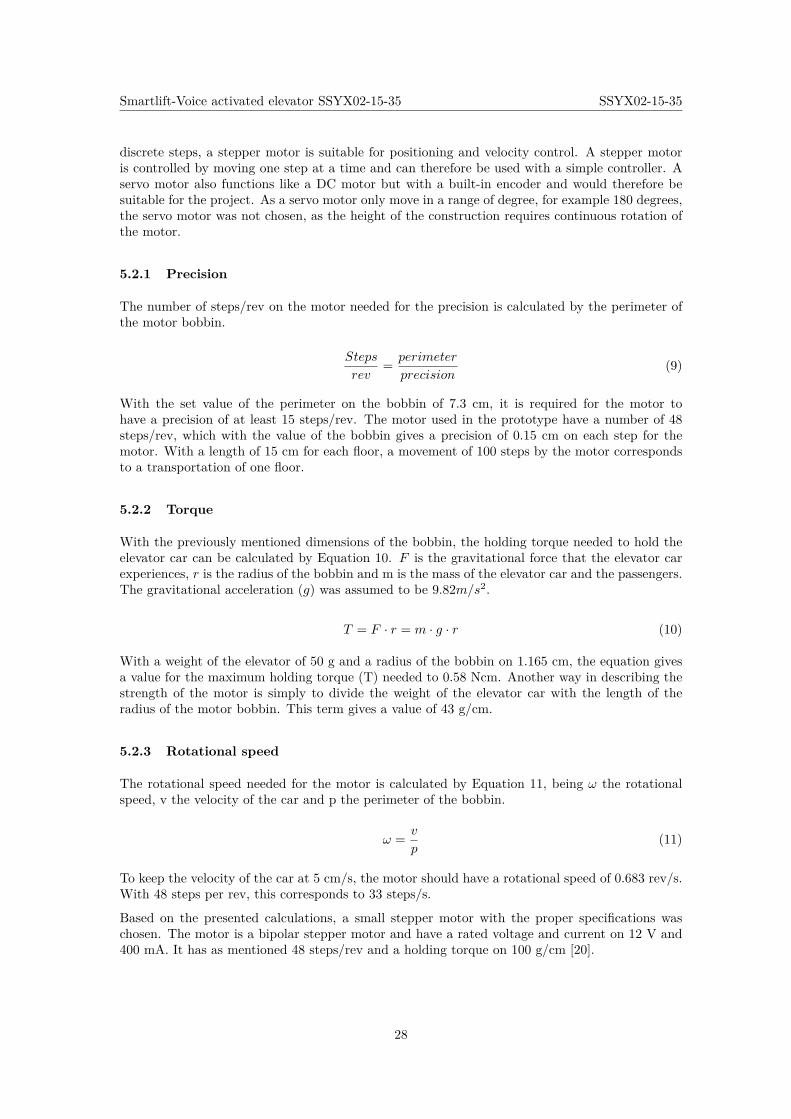
The connection between the ArduinoTM microcontroller and the stepper motor is done with amotor driver called A4988. The driver offers adjustable current limiting, overcurrent protectionand five different microstep resolutions. The driver operates from 8-35 V and can deliver up to 2A per coil, with additional cooling. The driver has a built-in translator making it easy to operate.Simply by inputting one pulse to the driver, the motor moves one step. The different functionsand the layout of the motor driver can be seen in Appendix B.
Thanks to the current limiting, the driver is able to run the motor with a higher voltage thanrequired from the motor. The higher voltage will ramp up the current faster and then alsomagnetise the coils faster, making the movement from one step to another faster than with alower voltage level. The current limitation in the driver prevents that the motor is damagedduring the drive.
To set the current limitation on the driver, the voltage on the “ref” pin is to be measured and thenthe current limitation can be calculated. The current limit is related to the reference voltage times2.5. The current limit on the stepper motor is 0.4 A, which corresponds to a reference voltage of0.16 V. But the current through the coils is limited to 70 % of the current limitation. Therefore,the reference voltage should instead be set to 0.22 V. By this setup, the motor gets a coil-currentof 0.4 A.
The different inputs to the driver are step, direction, reset and MS1, MS2, MS3. MSx sets themicrostepping, which can differ from full stepping to 1/16 steps. The driver needs to be connectedto a power supply, which is chosen as the 5 V pin on the ArduinoTM microcontroller. To be ableto increase the voltage supplied to the motor, the driver also needs an external power supply forthe motor; the power supply is set to 12 V. The two motor coils are connected directly to thedriver. The connection to the ArduinoTM and the stepper motor can be seen in Figure 21 [21].
Figure 21: Connection between ArduinoTM, motor driver and motor
The control of the driver from the ArduinoTM is made mainly through two pins: step and dir. Apulse on the step moves the motor one step. A high level on the dir moves the elevator car up anda low level moves the elevator car down.
29
Smartlift-Voice activated elevator SSYX02-15-35 SSYX02-15-35
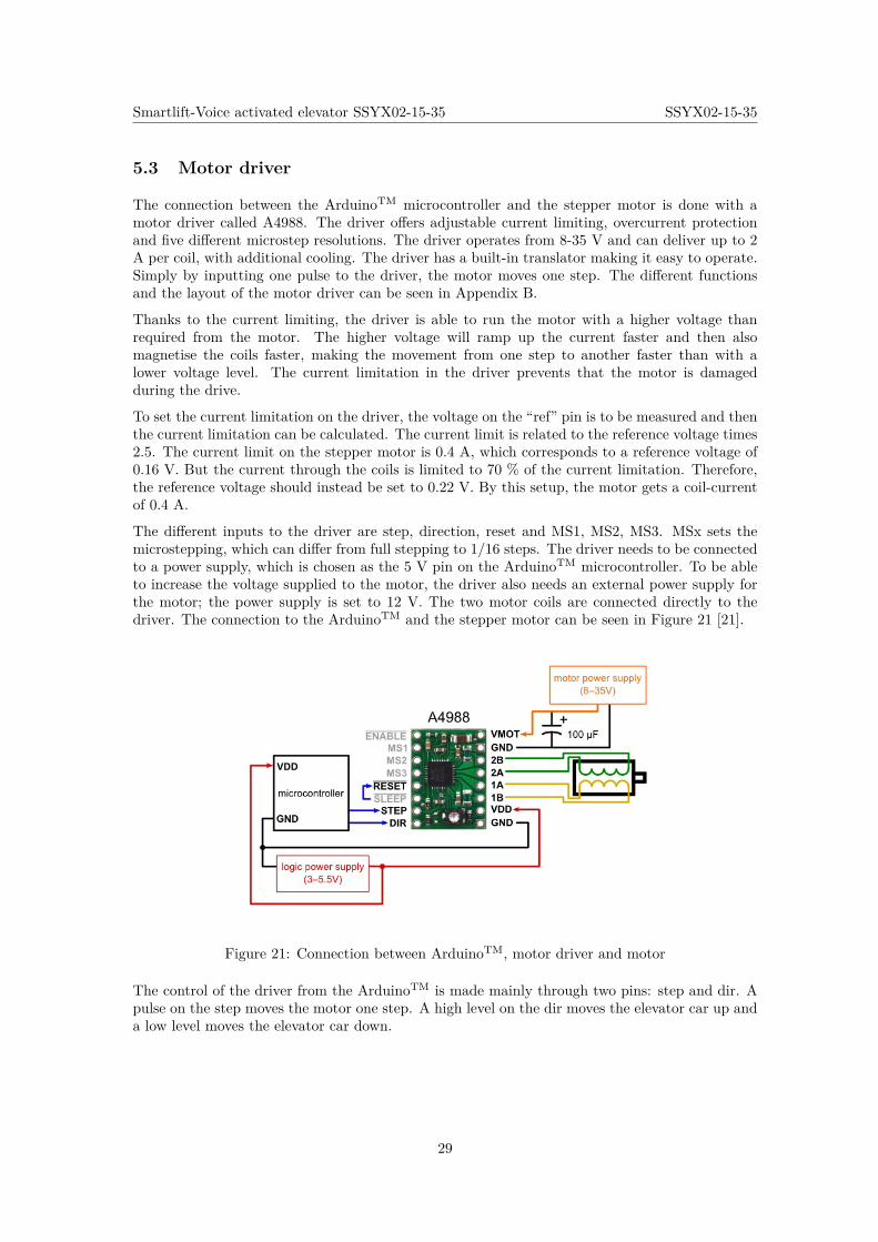
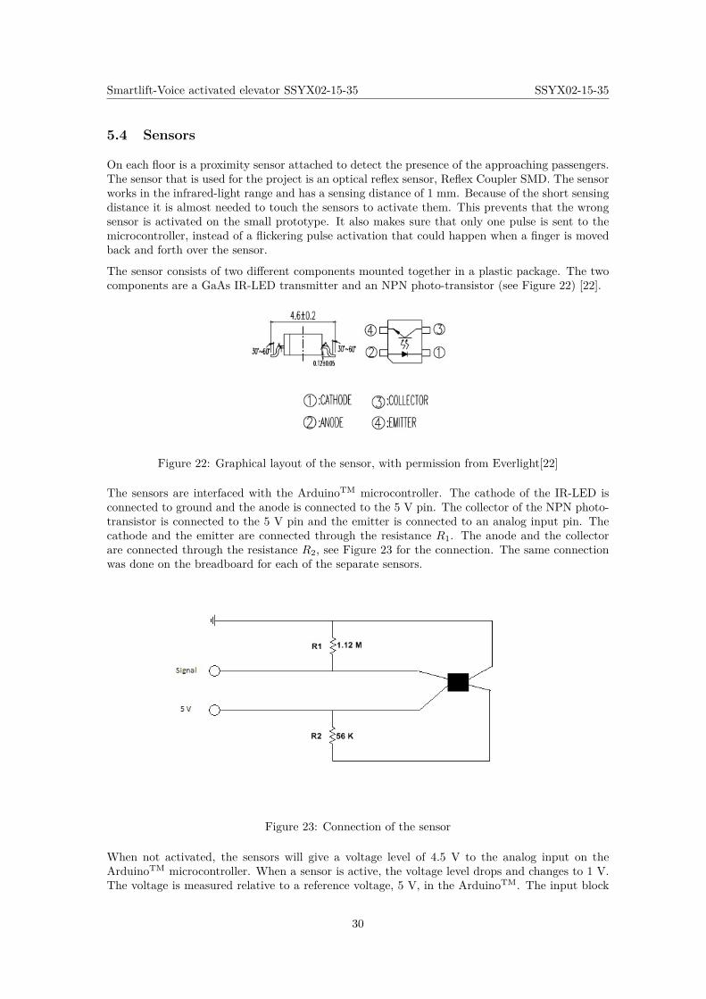
5.4 Sensors
On each floor is a proximity sensor attached to detect the presence of the approaching passengers.The sensor that is used for the project is an optical reflex sensor, Reflex Coupler SMD. The sensorworks in the infrared-light range and has a sensing distance of 1 mm. Because of the short sensingdistance it is almost needed to touch the sensors to activate them. This prevents that the wrongsensor is activated on the small prototype. It also makes sure that only one pulse is sent to themicrocontroller, instead of a flickering pulse activation that could happen when a finger is movedback and forth over the sensor.
The sensor consists of two different components mounted together in a plastic package. The twocomponents are a GaAs IR-LED transmitter and an NPN photo-transistor (see Figure 22) [22].
Figure 22: Graphical layout of the sensor, with permission from Everlight[22]
The sensors are interfaced with the ArduinoTM microcontroller. The cathode of the IR-LED isconnected to ground and the anode is connected to the 5 V pin. The collector of the NPN photo-transistor is connected to the 5 V pin and the emitter is connected to an analog input pin. Thecathode and the emitter are connected through the resistance R1. The anode and the collectorare connected through the resistance R2, see Figure 23 for the connection. The same connectionwas done on the breadboard for each of the separate sensors.
Figure 23: Connection of the sensor
When not activated, the sensors will give a voltage level of 4.5 V to the analog input on theArduinoTM microcontroller. When a sensor is active, the voltage level drops and changes to 1 V.The voltage is measured relative to a reference voltage, 5 V, in the ArduinoTM. The input block
30
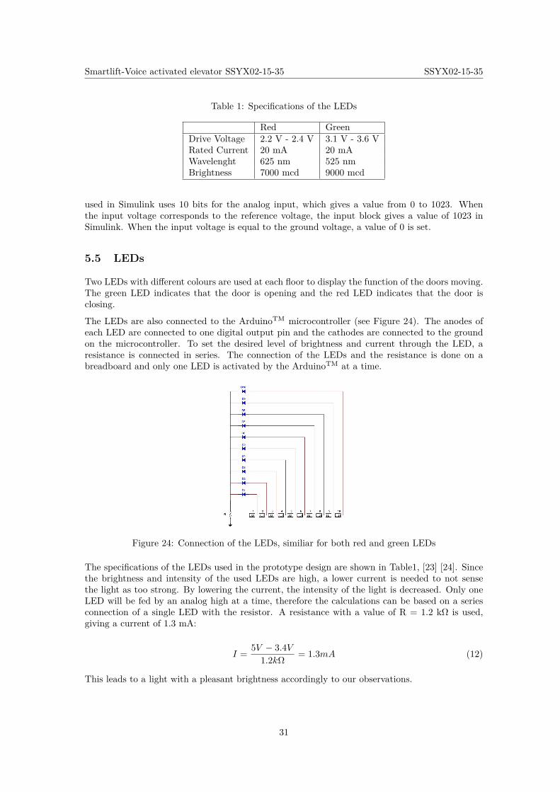
Smartlift-Voice activated elevator SSYX02-15-35 SSYX02-15-35
Table 1: Specifications of the LEDs
Red GreenDrive Voltage 2.2 V - 2.4 V 3.1 V - 3.6 VRated Current 20 mA 20 mAWavelenght 625 nm 525 nmBrightness 7000 mcd 9000 mcd
used in Simulink uses 10 bits for the analog input, which gives a value from 0 to 1023. Whenthe input voltage corresponds to the reference voltage, the input block gives a value of 1023 inSimulink. When the input voltage is equal to the ground voltage, a value of 0 is set.
5.5 LEDs
Two LEDs with different colours are used at each floor to display the function of the doors moving.The green LED indicates that the door is opening and the red LED indicates that the door isclosing.
The LEDs are also connected to the ArduinoTM microcontroller (see Figure 24). The anodes ofeach LED are connected to one digital output pin and the cathodes are connected to the groundon the microcontroller. To set the desired level of brightness and current through the LED, aresistance is connected in series. The connection of the LEDs and the resistance is done on abreadboard and only one LED is activated by the ArduinoTM at a time.
Figure 24: Connection of the LEDs, similiar for both red and green LEDs
The specifications of the LEDs used in the prototype design are shown in Table1, [23] [24]. Sincethe brightness and intensity of the used LEDs are high, a lower current is needed to not sensethe light as too strong. By lowering the current, the intensity of the light is decreased. Only oneLED will be fed by an analog high at a time, therefore the calculations can be based on a seriesconnection of a single LED with the resistor. A resistance with a value of R = 1.2 kΩ is used,giving a current of 1.3 mA:
I = 5V − 3.4V1.2kΩ = 1.3mA (12)
This leads to a light with a pleasant brightness accordingly to our observations.
31
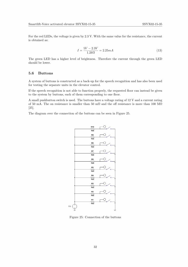
Smartlift-Voice activated elevator SSYX02-15-35 SSYX02-15-35
For the red LEDs, the voltage is given by 2.3 V. With the same value for the resistance, the currentis obtained as:
I = 5V − 2.3V1.2kΩ = 2.25mA (13)
The green LED has a higher level of brightness. Therefore the current through the green LEDshould be lower.
5.6 Buttons
A system of buttons is constructed as a back-up for the speech recognition and has also been usedfor testing the separate units in the elevator control.
If the speech recognition is not able to function properly, the requested floor can instead be givento the system by buttons, each of them corresponding to one floor.
A small pushbutton switch is used. The buttons have a voltage rating of 12 V and a current ratingof 50 mA. The on resistance is smaller than 50 mΩ and the off resistance is more than 100 MΩ[25].
The diagram over the connection of the buttons can be seen in Figure 25.
Figure 25: Connection of the buttons
32
Smartlift-Voice activated elevator SSYX02-15-35 SSYX02-15-35
5.7 Microphone
The microphone used in the project is called AKIRO USB MICROPHONE and it is suitable forthe project because of several reasons. First of all the microphone has a good sound quality withminimal background noise, which is important for the speech recognition. The microphone isalso connected by a USB-port, allowing a connection with the Raspberry Pi board. Lastly, themicrophone does not require any drivers to be installed before use [26].
5.8 Speaker
The speaker used in the project is a small speaker of 3 W (RMS). It has a built in battery with aplaytime of four hours and a range of 8 m. It has a wired connection with a 3.5 mm jack [27]
5.9 Microcontrollers
The speech recognition algorithms are very demanding in terms of data calculations. It is thereforenecessary to run the algorithm on a CPU with a high clock rate. The Raspberry Pi (RPi) 2 ModelB microcontroller board is equipped with a 900 MHz quad-core ARM Cortex-A7 CPU, whichis why it is used for this project [28]. The code is compiled with MATLAB, since its languagefeatures implemented functions suitable for signal processing, such as standardised Fourier trans-form methods and filters. The program is however created in Simulink, where the code is runningthrough MATLAB Functions. Hence, both the Simulink and MATLAB hardware-support pack-ages are used. The choice of using Simulink is justified by the fact that pure MATLAB-code doesnot run on the ARM processor (as it is too heavy). Since Simulink converts the MATLAB-codeto C, it is regarded a good option.
ArduinoTM Mega ADK was chosen for several reasons. First of all, the output voltage of itsgeneral-purpose-input-outputs (GPIOs) is 5V, which makes it easier to connect to sensors andactuators, compared to for example a Raspberry Pi, which has some GPIOs at 3.3V. Secondly, ithas more pins for inputs and outputs than most of the ArduinoTM boards, which is needed dueto the large number of sensors, LEDs, etc. Lastly, it has an USB connection, which is an optionto facilitate the connection with Raspberry Pi (which holds the speech recognition unit) [29].
An inventory list of all the products used in the project can be seen in Appendix F.
33
Smartlift-Voice activated elevator SSYX02-15-35 SSYX02-15-35
6 Environment and Sustainability
When constructing a prototype, it is important to thoughtfully select the materials to make asustainable design. In addition to making sure that the prototype fulfils the requirements regardingthe performance, it should also be taken into consideration that certain material choices affect theenvironment differently.
The main part of the prototype is built in aluminium. Recycling of aluminium saves 95 % of thetotal energy required to manufacture new metal. With the requirements set up for the prototype,this choice of material was good from sustainability aspect, assuming the metal is going to berecycled.[30]
The elevator car is printed with a 3D printer in plastic. This due to the complex design of theelevator car. Plastic is mostly made out of oil and when producing 1 kg of plastic, 2 kg of oil isrequired. When recycling plastic, it is almost unavoidable that different plastics are mixed, as aresult of which the mechanical properties often decreases and there are many residual products inthis process[31]. However, the plastic used for the elevator car is polylactic acid, which containsbiodegradable raw materials such as corn or sugarcane and are renewable.
Batteries are made by various chemicals, but always one hard metal. Some of these are toxicsuch as nickel and cadmium. These materials can cause damages on both humans as well as theenvironment and many of them are not possible to recycle. Therefore, the system was chosen tobe powered by cables instead of using batteries.
Nowadays, all real elevators use counter weight to minimise the energy consumption. However, inthe downscaled prototype it can be questioned how much impact a counter weight would have onthe energy consumption, since the weight of the elevator car is only 50g. Real elevators also havemore advanced pulley systems, with more pulleys. This could also be implied in the prototypeand would probably increase the precision of the elevator car but would probably not affect theenergy consumption remarkably.
34
Smartlift-Voice activated elevator SSYX02-15-35 SSYX02-15-35
7 Improvements and Issues in Upscaling
Through the process, additional features of the prototype have not been included. Some of themhave been added to the list of boundaries and some have not been considered because of the timelimit. Additional features and improvements can be considered in future works, as detailed in thefollowing subsections.
7.1 Required Improvements in the Downscaled Prototype
The prototype algorithms and functions can be improved for better performance and extendedwith additional features. The speech recognition system can be improved from many aspects. Itcan for example be improved by developing the classification process to increase the recognitionrate.
The SRU is activated after a proximity sensor is triggered. The system then records a speechsignal from the passenger for 3 seconds. After this time period, the microphone is no longeractive and the algorithm for the recognition is operating. This is an isolated speech recognitionsystem in which only one word can be recognised for each activation of the proximity sensors.An improvement of the system is to instead create a continuous system which listens for a longertime and is able to recognise several numbers and longer sentences. This way, the sensor would beactivated once, but different people can leave their requests on the same activation. This requiresa change in the speech recognition activation, as well as a modification in the elevator control.The control unit that sorts the queue is expecting only two numbers: one for where the passengerwill enter and one for where the passenger wants to exit the elevator. With several numbers as aninput, the algorithm for sorting the requested floors must function in a different way.
An additional operation for the SRU is to add a function with the possibility to change the recordednumber. This would be useful if the speech recognition did not work properly, if the backgroundnoise corrupted the signal or simply if the passenger would like to change the requested targetfloor. The SRU should thereby ask the passenger if the registered target floor is correct, to confirmthat this is the number that should be sent to the elevator control.
To improve the voice control, short words could be included in the SRU. These words can be"open" and "close" but also shorter phrases such as "open doors", "close doors" and for example"floor two". With phrases included in the recognition system, the system can handle a largerspectrum of situations. It is not possible to control the passenger to only say the direct number.If the passenger is to say "floor two" instead of only "two", the SRU in its present form, would notbe able to recognise the requested floor.
The function of the sensors can be improved, allowing the user to flicker the finger in front of thesensor without sending several activation pulses to the input of the elevator control. This could bedone by only activating the input signal when the sensor has been active for a number of samplepoints. The verge between not active and active on the sensor is then not as sharp and wouldgive a more accurate registration of the passengers. The sensors should not be activated by peoplethat walk past the elevator door without attempting to enter the elevator car. This could be donein the same way, by neglecting a voltage drop over the sensor if the level is not low for a certainnumber of sample times.
The total weight of the elevator car has not been taken into consideration during the project. Theelevator system should be developed to sense the total weight of the passengers and only move theelevator car if the upper weight limit is not reached. Also the elevator car should not stop and letpassengers enter, if the weight is close to the upper limit. The design of taking the orders outsideof the elevator allows even more advantages in the design of the elevator control. By knowinghow many people are waiting outside of the elevator car it is possible to decide if the elevator carshould stop or not. If the total weight is close to the upper limit and there are several people
35
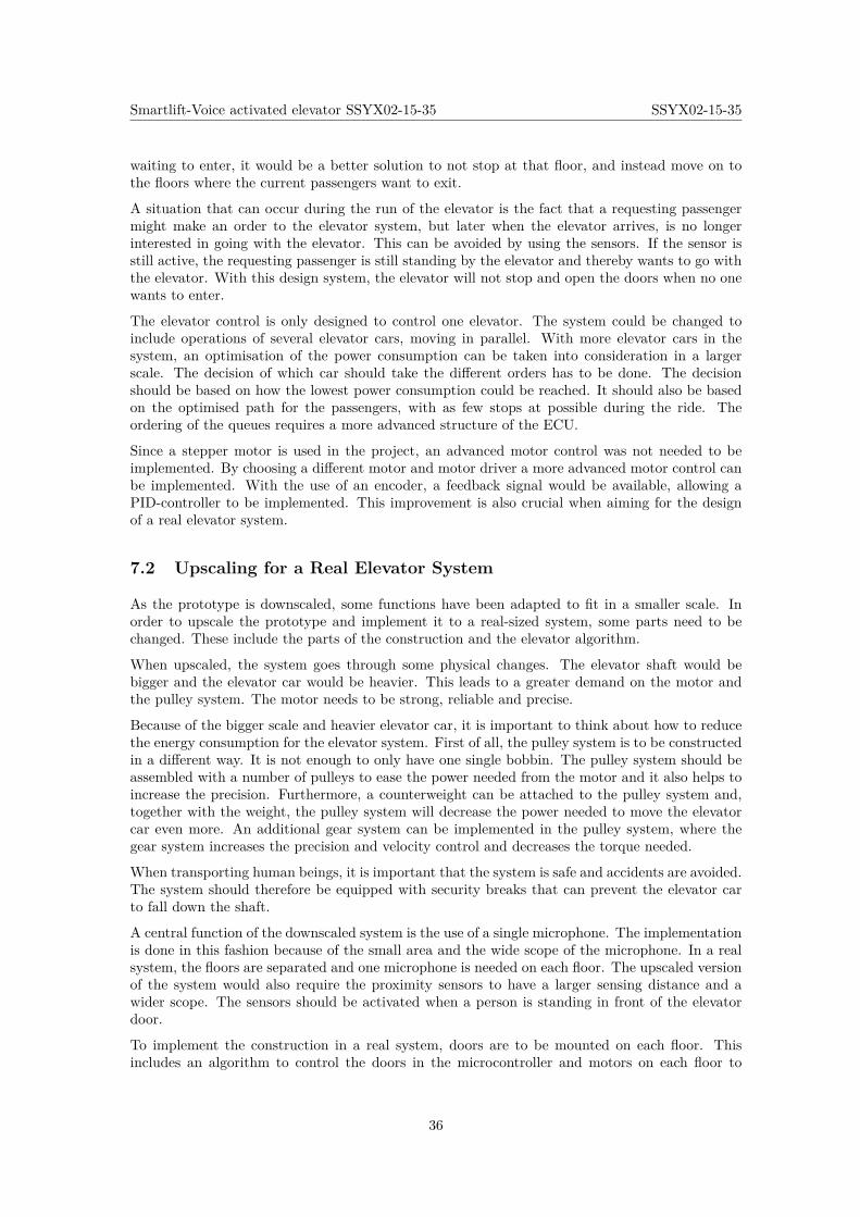
Smartlift-Voice activated elevator SSYX02-15-35 SSYX02-15-35
waiting to enter, it would be a better solution to not stop at that floor, and instead move on tothe floors where the current passengers want to exit.
A situation that can occur during the run of the elevator is the fact that a requesting passengermight make an order to the elevator system, but later when the elevator arrives, is no longerinterested in going with the elevator. This can be avoided by using the sensors. If the sensor isstill active, the requesting passenger is still standing by the elevator and thereby wants to go withthe elevator. With this design system, the elevator will not stop and open the doors when no onewants to enter.
The elevator control is only designed to control one elevator. The system could be changed toinclude operations of several elevator cars, moving in parallel. With more elevator cars in thesystem, an optimisation of the power consumption can be taken into consideration in a largerscale. The decision of which car should take the different orders has to be done. The decisionshould be based on how the lowest power consumption could be reached. It should also be basedon the optimised path for the passengers, with as few stops at possible during the ride. Theordering of the queues requires a more advanced structure of the ECU.
Since a stepper motor is used in the project, an advanced motor control was not needed to beimplemented. By choosing a different motor and motor driver a more advanced motor control canbe implemented. With the use of an encoder, a feedback signal would be available, allowing aPID-controller to be implemented. This improvement is also crucial when aiming for the designof a real elevator system.
7.2 Upscaling for a Real Elevator System
As the prototype is downscaled, some functions have been adapted to fit in a smaller scale. Inorder to upscale the prototype and implement it to a real-sized system, some parts need to bechanged. These include the parts of the construction and the elevator algorithm.
When upscaled, the system goes through some physical changes. The elevator shaft would bebigger and the elevator car would be heavier. This leads to a greater demand on the motor andthe pulley system. The motor needs to be strong, reliable and precise.
Because of the bigger scale and heavier elevator car, it is important to think about how to reducethe energy consumption for the elevator system. First of all, the pulley system is to be constructedin a different way. It is not enough to only have one single bobbin. The pulley system should beassembled with a number of pulleys to ease the power needed from the motor and it also helps toincrease the precision. Furthermore, a counterweight can be attached to the pulley system and,together with the weight, the pulley system will decrease the power needed to move the elevatorcar even more. An additional gear system can be implemented in the pulley system, where thegear system increases the precision and velocity control and decreases the torque needed.
When transporting human beings, it is important that the system is safe and accidents are avoided.The system should therefore be equipped with security breaks that can prevent the elevator carto fall down the shaft.
A central function of the downscaled system is the use of a single microphone. The implementationis done in this fashion because of the small area and the wide scope of the microphone. In a realsystem, the floors are separated and one microphone is needed on each floor. The upscaled versionof the system would also require the proximity sensors to have a larger sensing distance and awider scope. The sensors should be activated when a person is standing in front of the elevatordoor.
To implement the construction in a real system, doors are to be mounted on each floor. Thisincludes an algorithm to control the doors in the microcontroller and motors on each floor to
36

Smartlift-Voice activated elevator SSYX02-15-35 SSYX02-15-35
operate them. The doors also need sensors to detect if the opening is cleared before closing thedoor. The doors should only open when the elevator car is standing still.
To add extra security to the system, an emergency break operated inside of the elevator car bythe passengers should be implemented. The emergency break should stop the elevator car as fastas possible and yet in a safe way. A voice-operated emergency break requires some extra thought.It is to be decided which words are needed to be said. If the SRU does not function correctly, aphysical button might be needed to enhance the safety function.
37
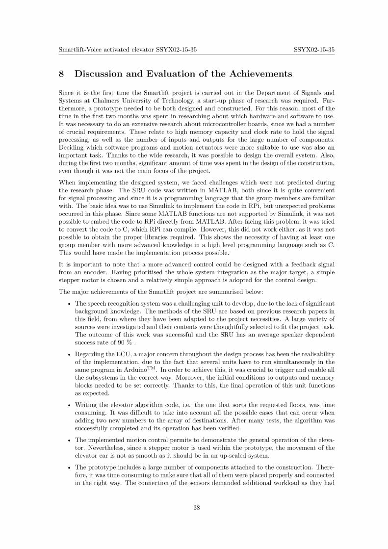
Smartlift-Voice activated elevator SSYX02-15-35 SSYX02-15-35
8 Discussion and Evaluation of the Achievements
Since it is the first time the Smartlift project is carried out in the Department of Signals andSystems at Chalmers University of Technology, a start-up phase of research was required. Fur-thermore, a prototype needed to be both designed and constructed. For this reason, most of thetime in the first two months was spent in researching about which hardware and software to use.It was necessary to do an extensive research about microcontroller boards, since we had a numberof crucial requirements. These relate to high memory capacity and clock rate to hold the signalprocessing, as well as the number of inputs and outputs for the large number of components.Deciding which software programs and motion actuators were more suitable to use was also animportant task. Thanks to the wide research, it was possible to design the overall system. Also,during the first two months, significant amount of time was spent in the design of the construction,even though it was not the main focus of the project.
When implementing the designed system, we faced challenges which were not predicted duringthe research phase. The SRU code was written in MATLAB, both since it is quite convenientfor signal processing and since it is a programming language that the group members are familiarwith. The basic idea was to use Simulink to implement the code in RPi, but unexpected problemsoccurred in this phase. Since some MATLAB functions are not supported by Simulink, it was notpossible to embed the code to RPi directly from MATLAB. After facing this problem, it was triedto convert the code to C, which RPi can compile. However, this did not work either, as it was notpossible to obtain the proper libraries required. This shows the necessity of having at least onegroup member with more advanced knowledge in a high level programming language such as C.This would have made the implementation process possible.
It is important to note that a more advanced control could be designed with a feedback signalfrom an encoder. Having prioritised the whole system integration as the major target, a simplestepper motor is chosen and a relatively simple approach is adopted for the control design.
The major achievements of the Smartlift project are summarised below:
• The speech recognition system was a challenging unit to develop, due to the lack of significantbackground knowledge. The methods of the SRU are based on previous research papers inthis field, from where they have been adapted to the project necessities. A large variety ofsources were investigated and their contents were thoughtfully selected to fit the project task.The outcome of this work was successful and the SRU has an average speaker dependentsuccess rate of 90 % .
• Regarding the ECU, a major concern throughout the design process has been the realisabilityof the implementation, due to the fact that several units have to run simultaneously in thesame program in ArduinoTM. In order to achieve this, it was crucial to trigger and enable allthe subsystems in the correct way. Moreover, the initial conditions to outputs and memoryblocks needed to be set correctly. Thanks to this, the final operation of this unit functionsas expected.
• Writing the elevator algorithm code, i.e. the one that sorts the requested floors, was timeconsuming. It was difficult to take into account all the possible cases that can occur whenadding two new numbers to the array of destinations. After many tests, the algorithm wassuccessfully completed and its operation has been verified.
• The implemented motion control permits to demonstrate the general operation of the eleva-tor. Nevertheless, since a stepper motor is used within the prototype, the movement of theelevator car is not as smooth as it should be in an up-scaled system.
• The prototype includes a large number of components attached to the construction. There-fore, it was time consuming to make sure that all of them were placed properly and connectedin the right way. The connection of the sensors demanded additional workload as they had
38

Smartlift-Voice activated elevator SSYX02-15-35 SSYX02-15-35
to be connected to individual circuits on the breadboard. The system with the differentcomponents was successfully achieved, including the connection of the motor driver, sensorsand LEDs.
The Smartlift project is completed without the integration of the speech recognition unit intothe elevator control unit. It has been a challenging and fruitful learning and experience for thegroup members. It is hoped that the implementation would be completed together with improveddesigns in the coming years.
39
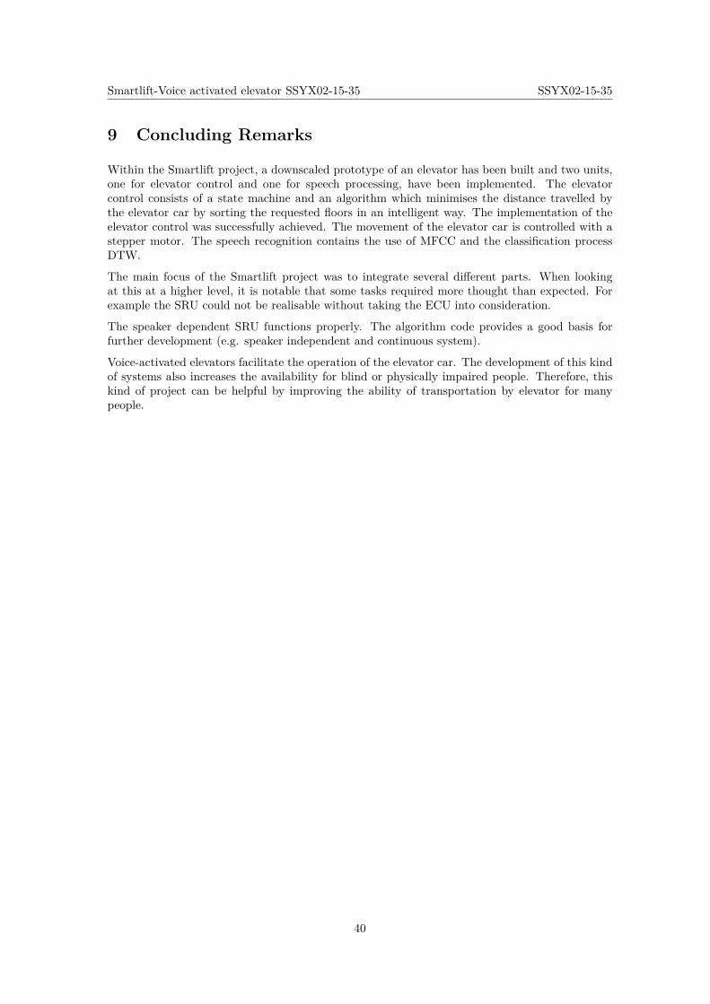
Smartlift-Voice activated elevator SSYX02-15-35 SSYX02-15-35
9 Concluding Remarks
Within the Smartlift project, a downscaled prototype of an elevator has been built and two units,one for elevator control and one for speech processing, have been implemented. The elevatorcontrol consists of a state machine and an algorithm which minimises the distance travelled bythe elevator car by sorting the requested floors in an intelligent way. The implementation of theelevator control was successfully achieved. The movement of the elevator car is controlled with astepper motor. The speech recognition contains the use of MFCC and the classification processDTW.
The main focus of the Smartlift project was to integrate several different parts. When lookingat this at a higher level, it is notable that some tasks required more thought than expected. Forexample the SRU could not be realisable without taking the ECU into consideration.
The speaker dependent SRU functions properly. The algorithm code provides a good basis forfurther development (e.g. speaker independent and continuous system).
Voice-activated elevators facilitate the operation of the elevator car. The development of this kindof systems also increases the availability for blind or physically impaired people. Therefore, thiskind of project can be helpful by improving the ability of transportation by elevator for manypeople.
40
Smartlift-Voice activated elevator SSYX02-15-35 SSYX02-15-35
References
[1] B. H. Juang and L. R. Rabiner, “Automatic Speech Recognition – A Brief History of theTechnology Development,” October 2004.
[2] G. I. of Technology and L. R. Rabiner, Automatic Speech Recognition – A Brief History ofthe Technology Development. PhD thesis, Georgia Institute of Technology, Atlanta, UnitedStates of America, October 2004.
[3] S. Satapathy et al., Proceedings of the 3rd International Conference on Frontiers of IntelligentComputing: Theory and Applications, vol. 1. Springer, 2008.
[4] J. Benesty et al., Springer Handbook of Speech Processing. Springer, 2014.
[5] M. R. Hasan et al., “Speaker identification using mel frequency cepstral coefficients,” tech.rep., Indian Institute of Technology Kanpur, City University of New York, U.S. Dept. ofDefense, Kanpur, India, New York, USA, Ft. Meade, USA, 1999.
[6] S. Umesh et al., “Fitting the mel scale,” tech. rep., Bangladesh University of Engineering andTechnology, Dhaka, Bangladesh, December 2004.
[7] A. University, “The mel frequency scale and coefficients,” tech. rep., Aalborg University,Aalborg, Denmark, 2004.
[8] R. Freeman, “Fundamentals of telecommunications,” tech. rep., John Wiley Sons, Inc, Scotts-dale, USA, November 1999.
[9] P. Felber, “Speech recognition: Report of an isolated word experiment,” tech. rep., IllinoisInstitute of Technology, Chicago, USA, April 2001.
[10] A. Aibinu et al., “Evaluating the effect of voice activity detection in isolated yoruba wordrecognition system,” tech. rep., International Islamic University, Kuala Lumpur, Malaysia,May 2011.
[11] VOCAL Technologies ltd, “Standard methods of vad.” http://www.vocal.com/voice-quality-enhancement/standard-methods-of-voice-activity-detection-vad.Accessed: 2015-03-17.
[12] S. Dev Dhingra et al., “Isolated speech recognition using mfcc and dtw,” tech. rep., Dept. ofECE, Faridabad, India, August 2013.
[13] L. R. Rabiner, “A tutorial on hidden markov models and selected applications in speechrecognition,” tech. rep., IEEE, New York, USA, 1989.
[14] Jyh-Shing Roger Jang, “Audio Signal Processing and Recognition.” http://www.cs.nthu.edu.tw/~jang. Accessed: 2015-04-12.
[15] S. V. Chapaner, “Spoken digits recognition using weighted mfcc and improved features for dy-namic time warping,” tech. rep., St. Francis Institute of Technology, Mumbai, India, February2012.
[16] S. Gupta et al., “Feature extraction using mfcc,” tech. rep., Universiti TecknologiPETRONAS, Perak, Malaysia, August 2013.
[17] T. Ganchev et al., “Comparative evaluation of various mfcc implementations on the speakerverification task,” tech. rep., University of Patras, Rion-Patras, Greece.
[18] L. Salhi and A. Cherif, “Robustness of auditory teager energy cepstrum coefficients for clas-sification of pathological and normal voices in noisy environments,” The Scientific WorldJournal, vol. Volume 2013, May 2013.
41
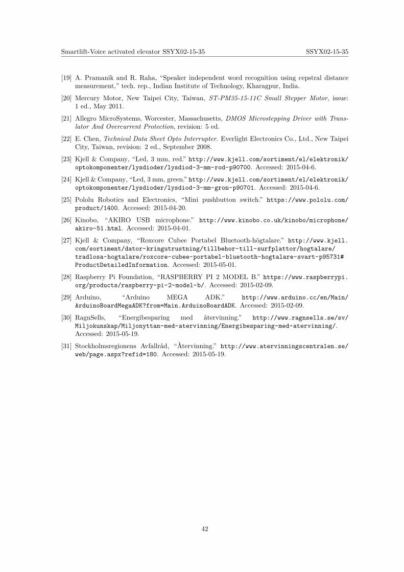
Smartlift-Voice activated elevator SSYX02-15-35 SSYX02-15-35
[19] A. Pramanik and R. Raha, “Speaker independent word recognition using cepstral distancemeasurement,” tech. rep., Indian Institute of Technology, Kharagpur, India.
[20] Mercury Motor, New Taipei City, Taiwan, ST-PM35-15-11C Small Stepper Motor, issue:1 ed., May 2011.
[21] Allegro MicroSystems, Worcester, Massachusetts, DMOS Microstepping Driver with Trans-lator And Overcurrent Protection, revision: 5 ed.
[22] E. Chen, Technical Data Sheet Opto Interrupter. Everlight Electronics Co., Ltd., New TaipeiCity, Taiwan, revision: 2 ed., September 2008.
[23] Kjell & Company, “Led, 3 mm, red.” http://www.kjell.com/sortiment/el/elektronik/optokomponenter/lysdioder/lysdiod-3-mm-rod-p90700. Accessed: 2015-04-6.
[24] Kjell & Company, “Led, 3 mm, green.” http://www.kjell.com/sortiment/el/elektronik/optokomponenter/lysdioder/lysdiod-3-mm-gron-p90701. Accessed: 2015-04-6.
[25] Pololu Robotics and Electronics, “Mini pushbutton switch.” https://www.pololu.com/product/1400. Accessed: 2015-04-20.
[26] Kinobo, “AKIRO USB microphone.” http://www.kinobo.co.uk/kinobo/microphone/akiro-51.html. Accessed: 2015-04-01.
[27] Kjell & Company, “Roxcore Cubee Portabel Bluetooth-högtalare.” http://www.kjell.com/sortiment/dator-kringutrustning/tillbehor-till-surfplattor/hogtalare/tradlosa-hogtalare/roxcore-cubee-portabel-bluetooth-hogtalare-svart-p95731#ProductDetailedInformation. Accessed: 2015-05-01.
[28] Raspberry Pi Foundation, “RASPBERRY PI 2 MODEL B.” https://www.raspberrypi.org/products/raspberry-pi-2-model-b/. Accessed: 2015-02-09.
[29] Arduino, “Arduino MEGA ADK.” http://www.arduino.cc/en/Main/ArduinoBoardMegaADK?from=Main.ArduinoBoardADK. Accessed: 2015-02-09.
[30] RagnSells, “Energibesparing med återvinning.” http://www.ragnsells.se/sv/Miljokunskap/Miljonyttan-med-atervinning/Energibesparing-med-atervinning/.Accessed: 2015-05-19.
[31] Stockholmsregionens Avfallråd, “Återvinning.” http://www.atervinningscentralen.se/web/page.aspx?refid=180. Accessed: 2015-05-19.
42
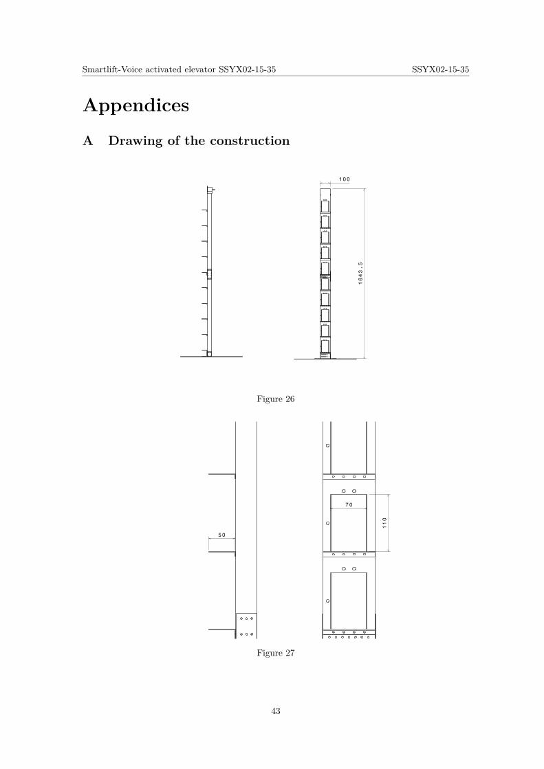
Smartlift-Voice activated elevator SSYX02-15-35 SSYX02-15-35
Appendices
A Drawing of the construction
100
1643.5
Figure 26
110
7 0
50
Figure 27
43
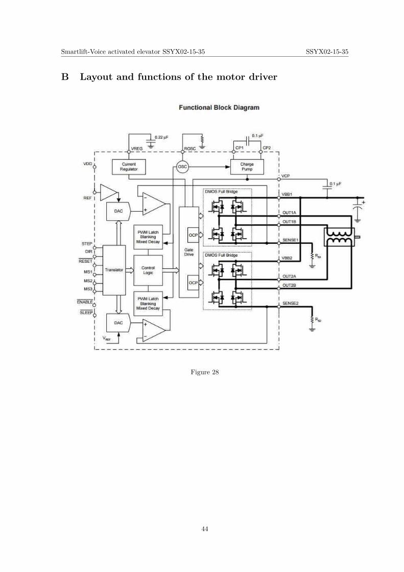
Smartlift-Voice activated elevator SSYX02-15-35 SSYX02-15-35
B Layout and functions of the motor driver
Figure 28
44
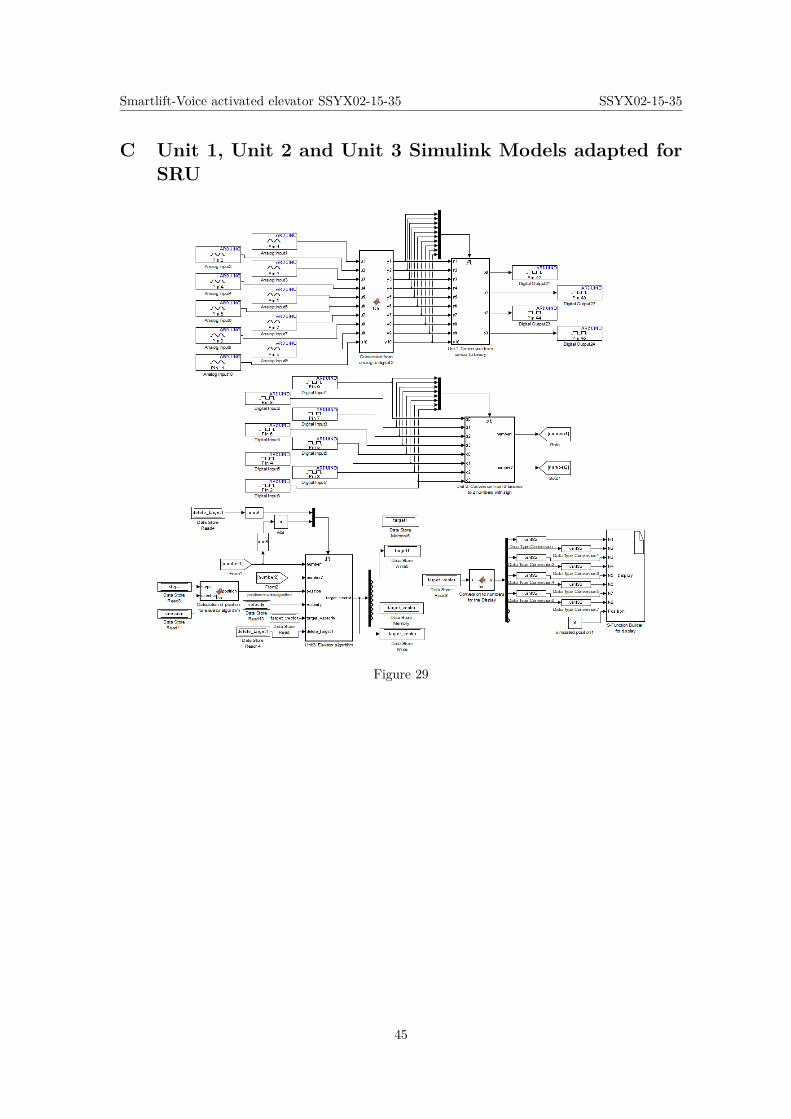
Smartlift-Voice activated elevator SSYX02-15-35 SSYX02-15-35
C Unit 1, Unit 2 and Unit 3 Simulink Models adapted forSRU
Figure 29
45
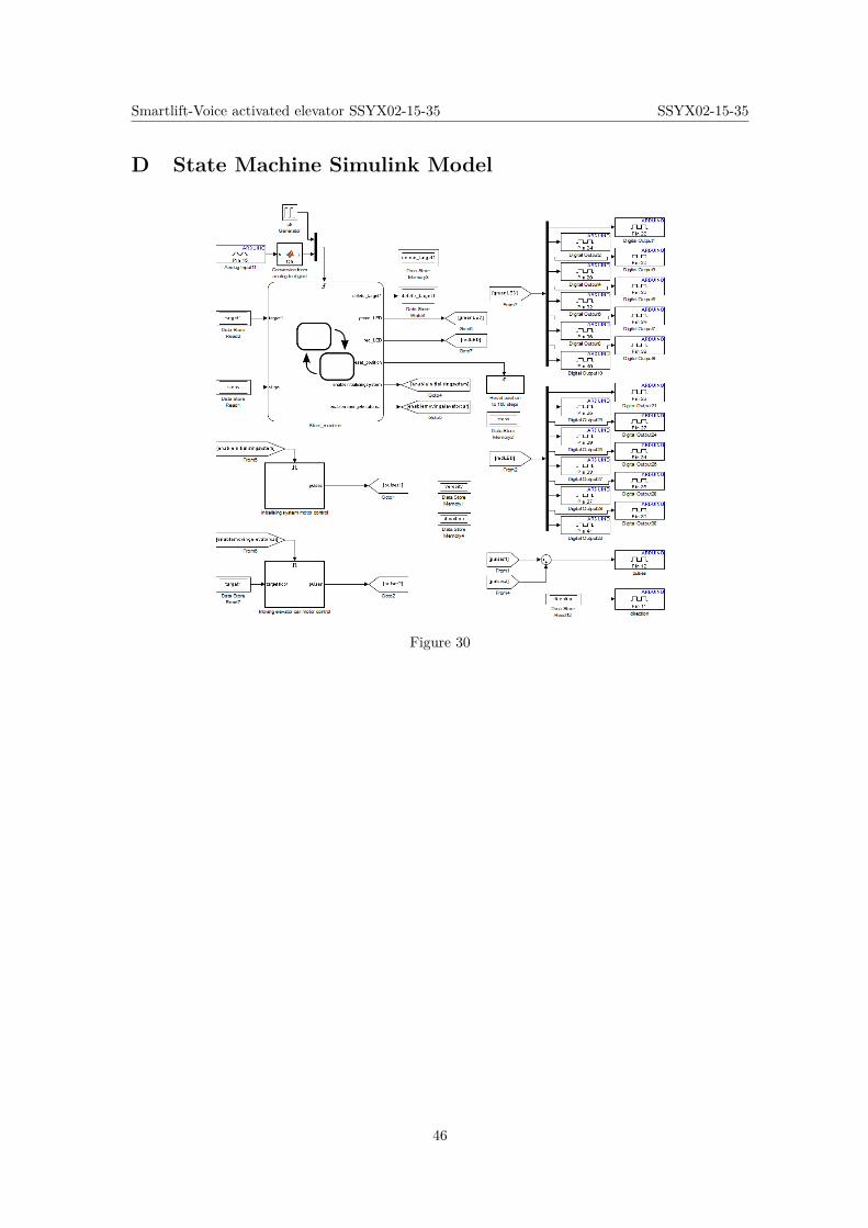
Smartlift-Voice activated elevator SSYX02-15-35 SSYX02-15-35
D State Machine Simulink Model
Figure 30
46
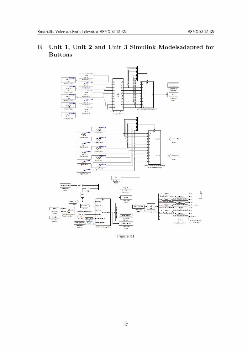
Smartlift-Voice activated elevator SSYX02-15-35 SSYX02-15-35
E Unit 1, Unit 2 and Unit 3 Simulink Modelsadapted forButtons
Figure 31
47
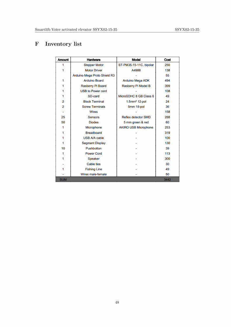
Smartlift-Voice activated elevator SSYX02-15-35 SSYX02-15-35
F Inventory list
48
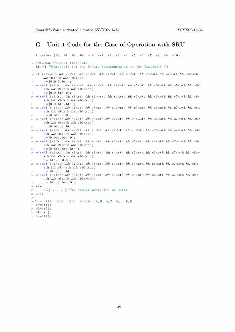
Smartlift-Voice activated elevator SSYX02-15-35 SSYX02-15-35
G Unit 1 Code for the Case of Operation with SRU
1 f unc t i on [ b0 , b1 , b2 , b3 ] = fcn ( s1 , s2 , s3 , s4 , s5 , s6 , s7 , s8 , s9 , s10 )2
3 sth =0.5 ; %senso r th r e sho ld4 bth=1; %thre sho ld f o r the binary communication to the Raspberry Pi5
6 i f ( s1>=sth && s2<sth && s3<sth && s4<sth && s5<sth && s6<sth && s7<sth && s8<sth&& s9<sth && s10<sth )
7 n=[0 ,0 ,0 , bth ] ;8 e l s e i f ( s1<sth && s2>=sth && s3<sth && s4<sth && s5<sth && s6<sth && s7<sth && s8<
sth && s9<sth && s10<sth )9 n=[0 ,0 , bth , 0 ] ;
10 e l s e i f ( s1<sth && s2<sth && s3>=sth && s4<sth && s5<sth && s6<sth && s7<sth && s8<sth && s9<sth && s10<sth )
11 n=[0 ,0 , bth , bth ] ;12 e l s e i f ( s1<sth && s2<sth && s3<sth && s4>=sth && s5<sth && s6<sth && s7<sth && s8<
sth && s9<sth && s10<sth )13 n=[0 , bth , 0 , 0 ] ;14 e l s e i f ( s1<sth && s2<sth && s3<sth && s4<sth && s5>=sth && s6<sth && s7<sth && s8<
sth && s9<sth && s10<sth )15 n=[0 , bth , 0 , bth ] ;16 e l s e i f ( s1<sth && s2<sth && s3<sth && s4<sth && s5<sth && s6>=sth && s7<sth && s8<
sth && s9<sth && s10<sth )17 n=[0 , bth , bth , 0 ] ;18 e l s e i f ( s1<sth && s2<sth && s3<sth && s4<sth && s5<sth && s6<sth && s7>=sth && s8<
sth && s9<sth && s10<sth )19 n=[0 , bth , bth , bth ] ;20 e l s e i f ( s1<sth && s2<sth && s3<sth && s4<sth && s5<sth && s6<sth && s7<sth && s8>=
sth && s9<sth && s10<sth )21 n=[bth , 0 , 0 , 0 ] ;22 e l s e i f ( s1<sth && s2<sth && s3<sth && s4<sth && s5<sth && s6<sth && s7<sth && s8<
sth && s9>=sth && s10<sth )23 n=[bth , 0 , 0 , bth ] ;24 e l s e i f ( s1<sth && s2<sth && s3<sth && s4<sth && s5<sth && s6<sth && s7<sth && s8<
sth && s9<sth && s10>=sth )25 n=[bth , 0 , bth , 0 ] ;26 e l s e27 n= [0 , 0 , 0 , 0 ] ; %no senso r a c t i va t ed or e r r o r28 end ;29
30 %n=[n (1 ) , n (2 ) , n (3 ) , n (4 ) ]= [ b_3 , b_2 , b_1 , b_0 ]31 b3=n (1) ;32 b2=n (2) ;33 b1=n (3) ;34 b0=n (4) ;
49
Smartlift-Voice activated elevator SSYX02-15-35 SSYX02-15-35
H Unit 2 Code for the Case of Operation with SRU
1 f unc t i on [ number1 , number2 ] = fcn ( a0 , a1 , a2 , a3 , c0 , c1 , c2 , c3 )2
3 bth=0.5; %thre sho ld f o r the binary communication from the Raspberry4
5 i f a0<=bth6 a0=1;7 e l s e8 a0=0;9 end
10
11 i f a1<=bth12 a1=1;13 e l s e14 a1=0;15 end16
17 i f a2<=bth18 a2=1;19 e l s e20 a2=0;21 end22
23 i f a3<=bth24 a3=1;25 e l s e26 a3=0;27 end28
29 i f c0<=bth30 c0=1;31 e l s e32 c0=0;33 end34
35 i f c1<=bth36 c1=1;37 e l s e38 c1=0;39 end40
41 i f c2<=bth42 c2=1;43 e l s e44 c2=0;45 end46
47 i f c3<=bth48 c3=1;49 e l s e50 c3=0;51 end52
53
54 a_natural=a0+a1∗2^1+a2∗2^2+a3 ∗2^3; %senso r f l o o r55 c_natural=c0+c1∗2^1+c2∗2^2+c3 ∗2^3; %de s i r ed f l o o r56
57 i f a_natural>0 && c_natural>0 && a_natural<=10 && c_natural<=1058 sus=a_natural−c_natural ;59 i f sus>0 %i t i s wanted to go down60 number1=−a_natural ;61 number2=−c_natural ;62 e l s e i f sus<0 %i t i s wanted to go up63 number1=+a_natural ;64 number2=+c_natural ;65 e l s e % error , the person does not want to change f l o o r
50

Smartlift-Voice activated elevator SSYX02-15-35 SSYX02-15-35
66 number1=0;67 number2=0;68 end69 e l s e %e r r o r in a or c70 number1=0;71 number2=0;72 end
51
Smartlift-Voice activated elevator SSYX02-15-35 SSYX02-15-35
I Unit 1 Code for the Case of Operation with Buttons
1 f unc t i on n = fcn ( s1 , s2 , s3 , s4 , s5 , s6 , s7 , s8 , s9 , s10 )2
3 sth =0.5 ; %senso r th r e sho ld4
5 i f ( s1>=sth && s2<sth && s3<sth && s4<sth && s5<sth && s6<sth && s7<sth && s8<sth&& s9<sth && s10<sth )
6 n=1;7 e l s e i f ( s1<sth && s2>=sth && s3<sth && s4<sth && s5<sth && s6<sth && s7<sth && s8<
sth && s9<sth && s10<sth )8 n=2;9 e l s e i f ( s1<sth && s2<sth && s3>=sth && s4<sth && s5<sth && s6<sth && s7<sth && s8<
sth && s9<sth && s10<sth )10 n=3;11 e l s e i f ( s1<sth && s2<sth && s3<sth && s4>=sth && s5<sth && s6<sth && s7<sth && s8<
sth && s9<sth && s10<sth )12 n=4;13 e l s e i f ( s1<sth && s2<sth && s3<sth && s4<sth && s5>=sth && s6<sth && s7<sth && s8<
sth && s9<sth && s10<sth )14 n=5;15 e l s e i f ( s1<sth && s2<sth && s3<sth && s4<sth && s5<sth && s6>=sth && s7<sth && s8<
sth && s9<sth && s10<sth )16 n=6;17 e l s e i f ( s1<sth && s2<sth && s3<sth && s4<sth && s5<sth && s6<sth && s7>=sth && s8<
sth && s9<sth && s10<sth )18 n=7;19 e l s e i f ( s1<sth && s2<sth && s3<sth && s4<sth && s5<sth && s6<sth && s7<sth && s8>=
sth && s9<sth && s10<sth )20 n=8;21 e l s e i f ( s1<sth && s2<sth && s3<sth && s4<sth && s5<sth && s6<sth && s7<sth && s8<
sth && s9>=sth && s10<sth )22 n=9;23 e l s e i f ( s1<sth && s2<sth && s3<sth && s4<sth && s5<sth && s6<sth && s7<sth && s8<
sth && s9<sth && s10>=sth )24 n=10;25 e l s e26 n=0; %no senso r a c t i va t ed or e r r o r27 end ;
52
Smartlift-Voice activated elevator SSYX02-15-35 SSYX02-15-35
J Unit 2 Code for the Case of Operation with Buttons
1 f unc t i on [ number1 , number2 ] = fcn ( f10 , f9 , f8 , f7 , f6 , f5 , f4 , f3 , f2 , f1 , a )2
3 bth=0.5; %thre sho ld f o r the binary communication to / from the raspber ry4
5 i f ( f1<=bth && f2>bth && f3>bth && f4>bth && f5>bth && f6>bth && f7>bth && f8>bth&& f9>bth && f10>bth )
6 c=1;7 e l s e i f ( f1>bth && f2<=bth && f3>bth && f4>bth && f5>bth && f6>bth && f7>bth && f8>
bth && f9>bth && f10>bth )8 c=2;9 e l s e i f ( f1>bth && f2>bth && f3<=bth && f4>bth && f5>bth && f6>bth && f7>bth && f8>
bth && f9>bth && f10>bth )10 c=3;11 e l s e i f ( f1>bth && f2>bth && f3>bth && f4<=bth && f5>bth && f6>bth && f7>bth && f8>
bth && f9>bth && f10>bth )12 c=4;13 e l s e i f ( f1>bth && f2>bth && f3>bth && f4>bth && f5<=bth && f6>bth && f7>bth && f8>
bth && f9>bth && f10>bth )14 c=5;15 e l s e i f ( f1>bth && f2>bth && f3>bth && f4>bth && f5>bth && f6<=bth && f7>bth && f8>
bth && f9>bth && f10>bth )16 c=6;17 e l s e i f ( f1>bth && f2>bth && f3>bth && f4>bth && f5>bth && f6>bth && f7<=bth && f8>
bth && f9>bth && f10>bth )18 c=7;19 e l s e i f ( f1>bth && f2>bth && f3>bth && f4>bth && f5>bth && f6>bth && f7>bth && f8<=
bth && f9>bth && f10>bth )20 c=8;21 e l s e i f ( f1>bth && f2>bth && f3>bth && f4>bth && f5>bth && f6>bth && f7>bth && f8>
bth && f9<=bth && f10>bth )22 c=9;23 e l s e i f ( f1>bth && f2>bth && f3>bth && f4>bth && f5>bth && f6>bth && f7>bth && f8>
bth && f9>bth && f10<=bth )24 c=10;25 e l s e26 c=0; %no senso r a c t i va t ed or e r r o r27 end ;28
29
30 a_natural=a ; %senso r f l o o r31 c_natural=c ; %de s i r ed f l o o r32
33 i f a_natural>0 && c_natural>0 && a_natural<=10 && c_natural<=1034 sus=a_natural−c_natural ;35
36 i f sus>0 %i t i s wanted to go down37 number1=−a_natural ;38 number2=−c_natural ;39 e l s e i f sus<0 %i t i s wanted to go up40 number1=+a_natural ;41 number2=+c_natural ;42 e l s e % error , the person does not want to change f l o o r43 number1=0;44 number2=0;45 end46 e l s e %e r r o r in a or c47 number1=0;48 number2=0;49 end
53
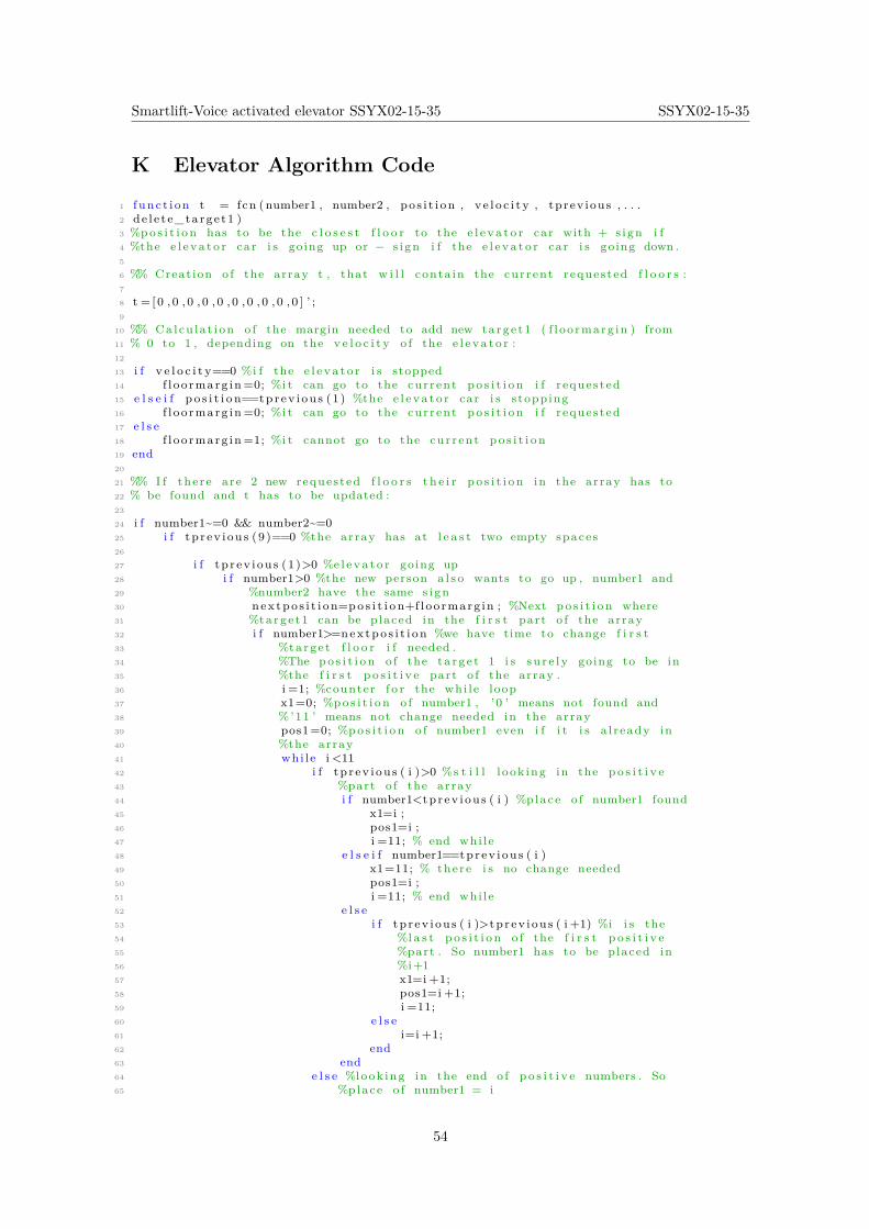
Smartlift-Voice activated elevator SSYX02-15-35 SSYX02-15-35
K Elevator Algorithm Code
1 f unc t i on t = fcn (number1 , number2 , po s i t i on , v e l o c i t y , tprev ious , . . .2 de l e t e_targe t1 )3 %po s i t i o n has to be the c l o s e s t f l o o r to the e l e v a t o r car with + s i gn i f4 %the e l e v a t o r car i s going up or − s i gn i f the e l e v a t o r car i s going down .5
6 %% Creat ion o f the array t , that w i l l conta in the cur rent reques ted f l o o r s :7
8 t = [ 0 , 0 , 0 , 0 , 0 , 0 , 0 , 0 , 0 , 0 ] ’ ;9
10 %% Calcu la t i on o f the margin needed to add new ta rge t1 ( f l oo rmarg in ) from11 % 0 to 1 , depending on the v e l o c i t y o f the e l e v a t o r :12
13 i f v e l o c i t y==0 %i f the e l e v a t o r i s stopped14 f l oo rmarg in =0; %i t can go to the cur rent po s i t i o n i f r eques ted15 e l s e i f p o s i t i o n==tprev i ou s (1 ) %the e l e v a t o r car i s s topping16 f l oo rmarg in =0; %i t can go to the cur rent po s i t i o n i f r eques ted17 e l s e18 f l oo rmarg in =1; %i t cannot go to the cur rent p o s i t i o n19 end20
21 %% I f the re are 2 new reques ted f l o o r s t h e i r p o s i t i o n in the array has to22 % be found and t has to be updated :23
24 i f number1~=0 && number2~=025 i f t p r ev i ou s (9 )==0 %the array has at l e a s t two empty spaces26
27 i f t p r ev i ou s (1 )>0 %e l e v a t o r going up28 i f number1>0 %the new person a l s o wants to go up , number1 and29 %number2 have the same s i gn30 nex tpo s i t i on=po s i t i o n+f loo rmarg in ; %Next po s i t i o n where31 %targe t1 can be placed in the f i r s t part o f the array32 i f number1>=nex tpo s i t i on %we have time to change f i r s t33 %targ e t f l o o r i f needed .34 %The po s i t i o n o f the t a r g e t 1 i s s u r e l y going to be in35 %the f i r s t p o s i t i v e part o f the array .36 i =1; %counter f o r the whi l e loop37 x1=0; %po s i t i o n o f number1 , ’0 ’ means not found and38 %’11 ’ means not change needed in the array39 pos1=0; %po s i t i o n o f number1 even i f i t i s a l r eady in40 %the array41 whi le i <1142 i f t p r ev i ou s ( i )>0 %s t i l l l ook ing in the p o s i t i v e43 %part o f the array44 i f number1<tpr ev i ou s ( i ) %p lace o f number1 found45 x1=i ;46 pos1=i ;47 i =11; % end whi l e48 e l s e i f number1==tprev i ou s ( i )49 x1=11; % there i s no change needed50 pos1=i ;51 i =11; % end whi l e52 e l s e53 i f t p r ev i ou s ( i )>tp r ev i ou s ( i +1) %i i s the54 %l a s t p o s i t i o n o f the f i r s t p o s i t i v e55 %part . So number1 has to be placed in56 %i+157 x1=i +1;58 pos1=i +1;59 i =11;60 e l s e61 i=i +1;62 end63 end64 e l s e %look ing in the end o f p o s i t i v e numbers . So65 %place o f number1 = i
54
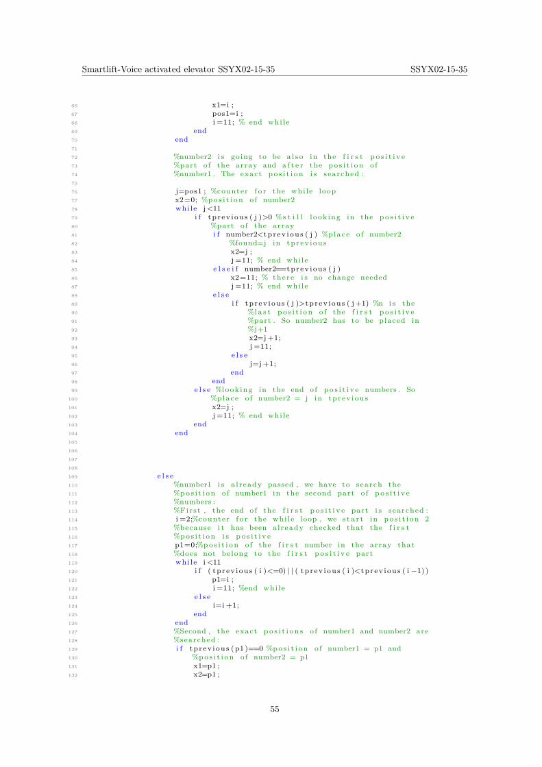
Smartlift-Voice activated elevator SSYX02-15-35 SSYX02-15-35
66 x1=i ;67 pos1=i ;68 i =11; % end whi l e69 end70 end71
72 %number2 i s going to be a l s o in the f i r s t p o s i t i v e73 %part o f the array and a f t e r the po s i t i o n o f74 %number1 . The exact p o s i t i o n i s searched :75
76 j=pos1 ; %counter f o r the whi l e loop77 x2=0; %po s i t i o n o f number278 whi le j <1179 i f t p r ev i ou s ( j )>0 %s t i l l l ook ing in the p o s i t i v e80 %part o f the array81 i f number2<tpr ev i ou s ( j ) %p lace o f number282 %found=j in tp r ev i ou s83 x2=j ;84 j =11; % end whi l e85 e l s e i f number2==tprev i ou s ( j )86 x2=11; % there i s no change needed87 j =11; % end whi l e88 e l s e89 i f t p r ev i ou s ( j )>tp r ev i ou s ( j +1) %n i s the90 %l a s t p o s i t i o n o f the f i r s t p o s i t i v e91 %part . So number2 has to be placed in92 %j+193 x2=j +1;94 j =11;95 e l s e96 j=j +1;97 end98 end99 e l s e %look ing in the end o f p o s i t i v e numbers . So
100 %place o f number2 = j in tp r ev i ou s101 x2=j ;102 j =11; % end whi l e103 end104 end105
106
107
108
109 e l s e110 %number1 i s a l r eady passed , we have to search the111 %po s i t i o n o f number1 in the second part o f p o s i t i v e112 %numbers :113 %Fir s t , the end o f the f i r s t p o s i t i v e part i s searched :114 i =2;%counter f o r the whi l e loop , we s t a r t in p o s i t i o n 2115 %because i t has been a l ready checked that the f i r s t116 %po s i t i o n i s p o s i t i v e117 p1=0;%po s i t i o n o f the f i r s t number in the array that118 %does not belong to the f i r s t p o s i t i v e part119 whi le i <11120 i f ( tp r ev i ou s ( i )<=0) | | ( tp r ev i ou s ( i )<tp r ev i ou s ( i −1) )121 p1=i ;122 i =11; %end whi l e123 e l s e124 i=i +1;125 end126 end127 %Second , the exact p o s i t i o n s o f number1 and number2 are128 %searched :129 i f t p r ev i ou s ( p1 )==0 %po s i t i o n o f number1 = p1 and130 %po s i t i o n o f number2 = p1131 x1=p1 ;132 x2=p1 ;
55
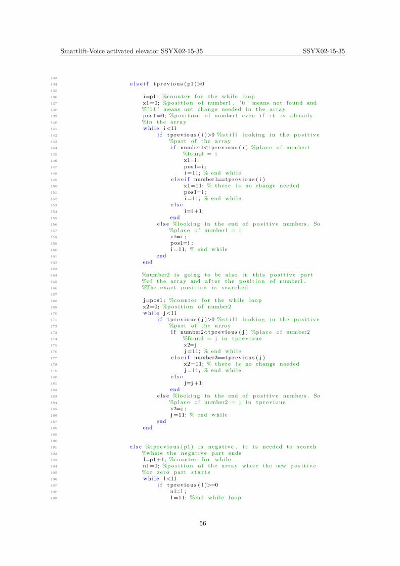
Smartlift-Voice activated elevator SSYX02-15-35 SSYX02-15-35
133
134 e l s e i f tp r ev i ou s ( p1 )>0135
136 i=p1 ; %counter f o r the whi l e loop137 x1=0; %po s i t i o n o f number1 , ’0 ’ means not found and138 %’11 ’ means not change needed in the array139 pos1=0; %po s i t i o n o f number1 even i f i t i s a l r eady140 %in the array141 whi le i <11142 i f t p r ev i ou s ( i )>0 %s t i l l l ook ing in the p o s i t i v e143 %part o f the array144 i f number1<tpr ev i ou s ( i ) %p lace o f number1145 %found = i146 x1=i ;147 pos1=i ;148 i =11; % end whi l e149 e l s e i f number1==tprev i ou s ( i )150 x1=11; % there i s no change needed151 pos1=i ;152 i =11; % end whi l e153 e l s e154 i=i +1;155 end156 e l s e %look ing in the end o f p o s i t i v e numbers . So157 %place o f number1 = i158 x1=i ;159 pos1=i ;160 i =11; % end whi l e161 end162 end163
164 %number2 i s going to be a l s o in t h i s p o s i t i v e part165 %of the array and a f t e r the po s i t i o n o f number1 .166 %The exact p o s i t i o n i s searched :167
168 j=pos1 ; %counter f o r the whi l e loop169 x2=0; %po s i t i o n o f number2170 whi le j <11171 i f t p r ev i ou s ( j )>0 %s t i l l l ook ing in the p o s i t i v e172 %part o f the array173 i f number2<tpr ev i ou s ( j ) %p lace o f number2174 %found = j in tp r ev i ou s175 x2=j ;176 j =11; % end whi l e177 e l s e i f number2==tprev i ou s ( j )178 x2=11; % there i s no change needed179 j =11; % end whi l e180 e l s e181 j=j +1;182 end183 e l s e %look ing in the end o f p o s i t i v e numbers . So184 %place o f number2 = j in tp r ev i ou s185 x2=j ;186 j =11; % end whi l e187 end188 end189
190
191 e l s e %tpr ev i ou s ( p1 ) i s negat ive , i t i s needed to search192 %where the negat ive part ends193 l=p1+1; %counter f o r whi l e194 n1=0; %po s i t i o n o f the array where the new po s i t i v e195 %or zero part s t a r t s196 whi le l <11197 i f t p r ev i ou s ( l )>=0198 n1=l ;199 l =11; %end whi l e loop
56
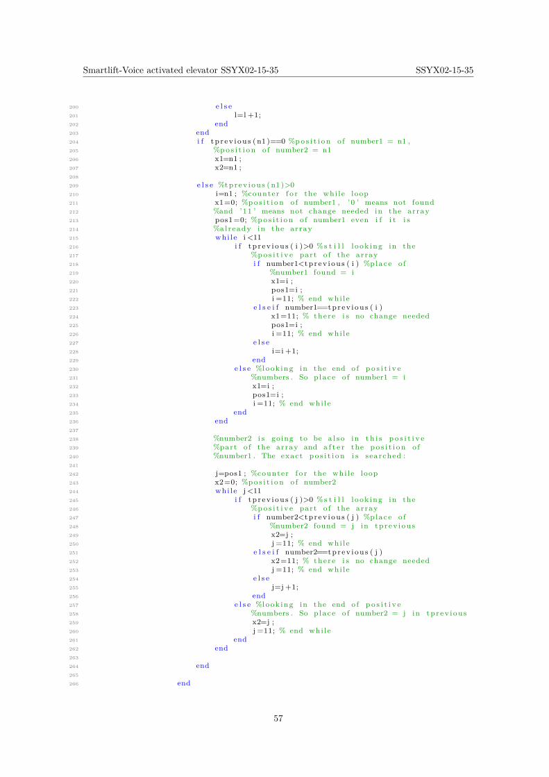
Smartlift-Voice activated elevator SSYX02-15-35 SSYX02-15-35
200 e l s e201 l=l +1;202 end203 end204 i f t p r ev i ou s ( n1 )==0 %po s i t i o n o f number1 = n1 ,205 %po s i t i o n o f number2 = n1206 x1=n1 ;207 x2=n1 ;208
209 e l s e %tpr ev i ou s ( n1 )>0210 i=n1 ; %counter f o r the whi l e loop211 x1=0; %po s i t i o n o f number1 , ’0 ’ means not found212 %and ’11 ’ means not change needed in the array213 pos1=0; %po s i t i o n o f number1 even i f i t i s214 %already in the array215 whi le i <11216 i f t p r ev i ou s ( i )>0 %s t i l l l ook ing in the217 %po s i t i v e part o f the array218 i f number1<tpr ev i ou s ( i ) %p lace o f219 %number1 found = i220 x1=i ;221 pos1=i ;222 i =11; % end whi l e223 e l s e i f number1==tprev i ou s ( i )224 x1=11; % there i s no change needed225 pos1=i ;226 i =11; % end whi l e227 e l s e228 i=i +1;229 end230 e l s e %look ing in the end o f p o s i t i v e231 %numbers . So p lace o f number1 = i232 x1=i ;233 pos1=i ;234 i =11; % end whi l e235 end236 end237
238 %number2 i s going to be a l s o in t h i s p o s i t i v e239 %part o f the array and a f t e r the po s i t i o n o f240 %number1 . The exact p o s i t i o n i s searched :241
242 j=pos1 ; %counter f o r the whi l e loop243 x2=0; %po s i t i o n o f number2244 whi le j <11245 i f t p r ev i ou s ( j )>0 %s t i l l l ook ing in the246 %po s i t i v e part o f the array247 i f number2<tpr ev i ou s ( j ) %p lace o f248 %number2 found = j in tp r ev i ou s249 x2=j ;250 j =11; % end whi l e251 e l s e i f number2==tprev i ou s ( j )252 x2=11; % there i s no change needed253 j =11; % end whi l e254 e l s e255 j=j +1;256 end257 e l s e %look ing in the end o f p o s i t i v e258 %numbers . So p lace o f number2 = j in tp r ev i ou s259 x2=j ;260 j =11; % end whi l e261 end262 end263
264 end265
266 end
57
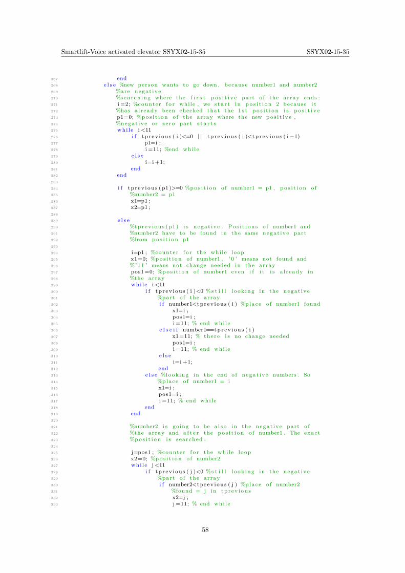
Smartlift-Voice activated elevator SSYX02-15-35 SSYX02-15-35
267 end268 e l s e %new person wants to go down , because number1 and number2269 %are negat ive270 %search ing where the f i r s t p o s i t i v e part o f the array ends :271 i =2; %counter f o r while , we s t a r t in po s i t i o n 2 because i t272 %has a l r eady been checked that the 1 s t p o s i t i o n i s p o s i t i v e273 p1=0; %po s i t i o n o f the array where the new po s i t i v e ,274 %negat ive or zero part s t a r t s275 whi le i <11276 i f t p r ev i ou s ( i )<=0 | | tp r ev i ou s ( i )<tp r ev i ou s ( i −1)277 p1=i ;278 i =11; %end whi l e279 e l s e280 i=i +1;281 end282 end283
284 i f t p r ev i ou s ( p1 )>=0 %po s i t i o n o f number1 = p1 , p o s i t i o n o f285 %number2 = p1286 x1=p1 ;287 x2=p1 ;288
289 e l s e290 %tprev i ou s ( p1 ) i s negat ive . Po s i t i on s o f number1 and291 %number2 have to be found in the same negat ive part292 %from po s i t i o n p1293
294 i=p1 ; %counter f o r the whi l e loop295 x1=0; %po s i t i o n o f number1 , ’0 ’ means not found and296 %’11 ’ means not change needed in the array297 pos1=0; %po s i t i o n o f number1 even i f i t i s a l r eady in298 %the array299 whi le i <11300 i f t p r ev i ou s ( i )<0 %s t i l l l ook ing in the negat ive301 %part o f the array302 i f number1<tpr ev i ou s ( i ) %p lace o f number1 found303 x1=i ;304 pos1=i ;305 i =11; % end whi l e306 e l s e i f number1==tprev i ou s ( i )307 x1=11; % there i s no change needed308 pos1=i ;309 i =11; % end whi l e310 e l s e311 i=i +1;312 end313 e l s e %look ing in the end o f negat ive numbers . So314 %place o f number1 = i315 x1=i ;316 pos1=i ;317 i =11; % end whi l e318 end319 end320
321 %number2 i s going to be a l s o in the negat ive part o f322 %the array and a f t e r the po s i t i o n o f number1 . The exact323 %po s i t i o n i s searched :324
325 j=pos1 ; %counter f o r the whi l e loop326 x2=0; %po s i t i o n o f number2327 whi le j <11328 i f t p r ev i ou s ( j )<0 %s t i l l l ook ing in the negat ive329 %part o f the array330 i f number2<tpr ev i ou s ( j ) %p lace o f number2331 %found = j in tp r ev i ou s332 x2=j ;333 j =11; % end whi l e
58
Smartlift-Voice activated elevator SSYX02-15-35 SSYX02-15-35
334 e l s e i f number2==tprev i ou s ( j )335 x2=11; % there i s no change needed336 j =11; % end whi l e337 e l s e338 j=j +1;339 end340 e l s e %look ing in the end o f negat ive numbers . So341 %place o f number2 = j in tp r ev i ou s342 x2=j ;343 j =11; % end whi l e344 end345 end346
347 end348
349 end350 e l s e i f tp r ev i ou s (1 )<0 % e l e v a t o r going down351
352 i f number1<0 % the new person a l s o wants to go down , number1353 %and number2 have the same s i gn354
355 nex tpo s i t i on=po s i t i o n+f loo rmarg in ; %Next po s i t i o n where356 %targe t1 can be placed in the f i r s t part o f the array357 i f number1>=nex tpo s i t i on %we have time to change f i r s t358 %targ e t f l o o r i f needed .359 %The po s i t i o n o f the t a r g e t 1 i s s u r e l y going to be in360 %the f i r s t negat ive part o f the array .361
362 i =1; %counter f o r the whi l e loop363 x1=0; %po s i t i o n o f number1 , ’0 ’ means not found and364 %’11 ’ means not change needed in the array365 pos1=0; %po s i t i o n o f number1 even i f i t i s a l r eady in366 %the array367 whi le i <11368 i f t p r ev i ou s ( i )<0 %s t i l l l ook ing in the negat ive369 %part o f the array370 i f number1<tpr ev i ou s ( i ) %p lace o f number1 found371 x1=i ;372 pos1=i ;373 i =11; % end whi l e374 e l s e i f number1==tprev i ou s ( i )375 x1=11; % there i s no change needed376 pos1=i ;377 i =11; % end whi l e378 e l s e379 i f t p r ev i ou s ( i )>tp r ev i ou s ( i +1) %i i s the380 %l a s t p o s i t i o n o f the f i r s t negat ive381 %part . So number1 has to be placed in382 %i+1383 x1=i +1;384 pos1=i +1;385 i =11;386 e l s e387 i=i +1;388 end389 end390 e l s e %look ing in the end o f p o s i t i v e numbers . So391 %place o f number1 = i392 x1=i ;393 pos1=i ;394 i =11; % end whi l e395 end396 end397
398 %number2 i s going to be a l s o in the f i r s t negat ive399 %part o f the array and a f t e r the po s i t i o n o f400 %number1 . The exact p o s i t i o n i s searched :
59
Smartlift-Voice activated elevator SSYX02-15-35 SSYX02-15-35
401
402 j=pos1 ; %counter f o r the whi l e loop403 x2=0; %po s i t i o n o f number2404 whi le j <11405 i f t p r ev i ou s ( j )<0 %s t i l l l ook ing in the negat ive406 %part o f the array407 i f number2<tpr ev i ou s ( j ) %p lace o f number2408 %found = j in tp r ev i ou s409 x2=j ;410 j =11; % end whi l e411 e l s e i f number2==tprev i ou s ( j )412 x2=11; % there i s no change needed413 j =11; % end whi l e414 e l s e415 i f t p r ev i ou s ( j )>tp r ev i ou s ( j +1) %n i s the416 %l a s t p o s i t i o n o f the f i r s t negat ive417 %part . So number2 has to be placed in418 %j+1419 x2=j +1;420 j =11;421 e l s e422 j=j +1;423 end424 end425 e l s e %look ing in the end o f p o s i t i v e numbers . So426 %place o f number2 = j in tp r ev i ou s427 x2=j ;428 j =11; % end whi l e429 end430 end431
432 e l s e433 %number1 i s a l r eady passed , we have to search the434 %po s i t i o n o f number1 in the second part o f negat ive435 %numbers :436 %Fir s t , the end o f the f i r s t negat ive part i s searched :437 i =2;%counter f o r the whi l e loop , we s t a r t in p o s i t i o n 2438 %because i t has been a l ready checked that the f i r s t439 %po s i t i o n i s negat ive440 n1=0;%po s i t i o n o f the f i r s t number in the array that441 %does not belong to the f i r s t negat ive part442 whi le i <11443 i f t p r ev i ou s ( i )>=0 | | tp r ev i ou s ( i )<tp r ev i ou s ( i −1)444 n1=i ;445 i =11; %end whi l e446 e l s e447 i=i +1;448 end449 end450 %Second , the exact p o s i t i o n o f number1 and number2 are451 %searched :452
453 i f t p r ev i ou s ( n1 )==0 %po s i t i o n o f number1 = n1 and454 %po s i t i o n o f number2 = n1455 x1=n1 ;456 x2=n1 ;457
458 e l s e i f tp r ev i ou s ( n1 )<0459
460 i=n1 ; %counter f o r the whi l e loop461 x1=0; %po s i t i o n o f number1 , ’0 ’ means not found and462 %’11 ’ means not change needed in the array463 pos1=0; %po s i t i o n o f number1 even i f i t i s a l r eady464 %in the array465 whi le i <11466 i f t p r ev i ou s ( i )<0 %s t i l l l ook ing in the negat ive467 %part o f the array
60

Smartlift-Voice activated elevator SSYX02-15-35 SSYX02-15-35
468 i f number1<tpr ev i ou s ( i ) %p lace o f number1469 %found = i470 x1=i ;471 pos1=i ;472 i =11; % end whi l e473 e l s e i f number1==tprev i ou s ( i )474 x1=11; % there i s no change needed475 pos1=i ;476 i =11; % end whi l e477 e l s e478 i=i +1;479 end480 e l s e %look ing in the end o f negat ive numbers . So481 %place o f number1 = i482 x1=i ;483 pos1=i ;484 i =11; % end whi l e485 end486 end487
488 %number2 i s going to be a l s o in t h i s negat ive part489 %of the array and a f t e r the po s i t i o n o f number1 .490 %The exact p o s i t i o n i s searched :491
492 j=pos1 ; %counter f o r the whi l e loop493 x2=0; %po s i t i o n o f number2494 whi le j <11495 i f t p r ev i ou s ( j )<0 %s t i l l l ook ing in the negat ive496 %part o f the array497 i f number2<tpr ev i ou s ( j ) %p lace o f number2498 %found = j in tp r ev i ou s499 x2=j ;500 j =11; % end whi l e501 e l s e i f number2==tprev i ou s ( j )502 x2=11; % there i s no change needed503 j =11; % end whi l e504 e l s e505 j=j +1;506 end507 e l s e %look ing in the end o f negat ive numbers . So508 %place o f number2 = j in tp r ev i ou s509 x2=j ;510 j =11; % end whi l e511 end512 end513
514
515 e l s e %tpr ev i ou s ( n1 ) i s po s i t i v e , i t i s needed to search516 %where the p o s i t i v e part ends517 l=n1+1; %counter f o r whi l e518 p1=0; %po s i t i o n o f the array where the new negat ive519 %or zero part s t a r t s520 whi le l <11521 i f t p r ev i ou s ( l )<=0522 p1=l ;523 l =11; %end whi l e loop524 e l s e525 l=l +1;526 end527 end528 i f t p r ev i ou s ( p1 )==0 %po s i t i o n o f number1 = p1 ,529 %po s i t i o n o f number2 = p1530 x1=p1 ;531 x2=p1 ;532
533 e l s e %tpr ev i ou s ( p1 )<0534 i=p1 ; %counter f o r the whi l e loop
61
Smartlift-Voice activated elevator SSYX02-15-35 SSYX02-15-35
535 x1=0; %po s i t i o n o f number1 , ’0 ’ means not found536 %and ’11 ’ means not change needed in the array537 pos1=0; %po s i t i o n o f number1 even i f i t i s538 %already in the array539 whi le i <11540 i f t p r ev i ou s ( i )<0 %s t i l l l ook ing in the541 %negat ive part o f the array542 i f number1<tpr ev i ou s ( i ) %p lace o f543 %number1 found = i544 x1=i ;545 pos1=i ;546 i =11; % end whi l e547 e l s e i f number1==tprev i ou s ( i )548 x1=11; % there i s no change needed549 pos1=i ;550 i =11; % end whi l e551 e l s e552 i=i +1;553 end554 e l s e %look ing in the end o f negat ive555 %numbers . So p lace o f number1 = i556 x1=i ;557 pos1=i ;558 i =11; % end whi l e559 end560 end561
562 %number2 i s going to be a l s o in t h i s negat ive563 %part o f the array and a f t e r the po s i t i o n o f564 %number1 . The exact p o s i t i o n i s searched :565
566 j=pos1 ; %counter f o r the whi l e loop567 x2=0; %po s i t i o n o f number2568 whi le j <11569 i f t p r ev i ou s ( j )<0 %s t i l l l ook ing in the570 %negat ive part o f the array571 i f number2<tpr ev i ou s ( j ) %p lace o f572 %number2 found = j in tp r ev i ou s573 x2=j ;574 j =11; % end whi l e575 e l s e i f number2==tprev i ou s ( j )576 x2=11; % there i s no change needed577 j =11; % end whi l e578 e l s e579 j=j +1;580 end581 e l s e %look ing in the end o f negat ive582 %numbers . So p lace o f number2 = j in583 %tprev i ou s584 x2=j ;585 j =11; % end whi l e586 end587 end588
589 end590
591 end592
593 end594 e l s e %new person wants to go up , because number1 and number2595 %are p o s i t i v e596
597 %search ing where the f i r s t negat ive part o f the array ends :598 i =2; %counter f o r while , we s t a r t in po s i t i o n 2 because i t599 %has been a l r eady checked that the 1 s t p o s i t i o n i s negat ive600 n1=0; %po s i t i o n o f the array where the new negat ive ,601 %po s i t i v e or zero part s t a r t s
62
Smartlift-Voice activated elevator SSYX02-15-35 SSYX02-15-35
602 whi le i <11603 i f t p r ev i ou s ( i )>=0 | | tp r ev i ou s ( i )<tp r ev i ou s ( i −1)604 n1=i ;605 i =11; %end whi l e606 e l s e607 i=i +1;608 end609 end610
611 i f t p r ev i ou s ( n1 )<=0 %po s i t i o n o f number1 = p1 , p o s i t i o n o f612 %number2 = p1613 x1=n1 ;614 x2=n1 ;615
616 e l s e617 %tprev i ou s ( p1 ) i s p o s i t i v e . Po s i t i on s o f number1 and618 %number2 have to be found in the same p o s i t i v e part619 %from po s i t i o n n1620
621 i=n1 ; %counter f o r the whi l e loop622 x1=0; %po s i t i o n o f number1 , ’0 ’ means not found and623 %’11 ’ means not change needed in the array624 pos1=0; %po s i t i o n o f number1 even i f i t i s a l r eady in625 %the array626 whi le i <11627 i f t p r ev i ou s ( i )>0 %s t i l l l ook ing in the p o s i t i v e628 %part o f the array629 i f number1<tpr ev i ou s ( i ) %p lace o f number1 found630 x1=i ;631 pos1=i ;632 i =11; % end whi l e633 e l s e i f number1==tprev i ou s ( i )634 x1=11; % there i s no change needed635 pos1=i ;636 i =11; % end whi l e637 e l s e638 i=i +1;639 end640 e l s e %look ing in the end o f p o s i t i v e numbers . So641 %place o f number1 = i642 x1=i ;643 pos1=i ;644 i =11; % end whi l e645 end646 end647
648 %number2 i s going to be a l s o in the p o s i t i v e part o f649 %the array and a f t e r the po s i t i o n o f number1 . The exact650 %po s i t i o n i s searched :651
652 j=pos1 ; %counter f o r the whi l e loop653 x2=0; %po s i t i o n o f number2654 whi le j <11655 i f t p r ev i ou s ( j )>0 %s t i l l l ook ing in the p o s i t i v e656 %part o f the array657 i f number2<tpr ev i ou s ( j ) %p lace o f number2658 %found = j in tp r ev i ou s659 x2=j ;660 j =11; % end whi l e661 e l s e i f number2==tprev i ou s ( j )662 x2=11; % there i s no change needed663 j =11; % end whi l e664 e l s e665 j=j +1;666 end667 e l s e %look ing in the end o f p o s i t i v e numbers . So668 %place o f number2 = j in tp r ev i ou s
63
Smartlift-Voice activated elevator SSYX02-15-35 SSYX02-15-35
669 x2=j ;670 j =11; % end whi l e671 end672 end673
674 end675
676 end677
678 e l s e %e l e v a t o r i s stopped679 x1=1;680 x2=1;681
682 end683
684 e l s e %there i s not enough space in the array to add new f l o o r s685 x1=11;686 x2=11;687
688 end689
690 e l s e %there are not new reques ted f l o o r s691 x1=11;692 x2=11;693
694 end695 %% Update t :696
697 i f x1<11 %i t i s needed to add number1 in the array698 i f x1>1699 t ( 1 : x1−1)=tpr ev i ou s ( 1 : x1−1) ;700 e l s e701 end702 t ( x1 )=number1 ;703 i f x2<11 %i t i s needed to add number2 in the array704 t ( x1+1:x2 )=tpr ev i ou s ( x1 : x2−1) ;705 t ( x2+1)=number2 ;706 t ( x2+2:10)=tpr ev i ou s ( x2 : 8 ) ;707
708 e l s e %number2 i s a l r eady in the array709 t ( x1+1:10)=tpr ev i ou s ( x1 : 9 ) ;710
711 end712 e l s e %number1 i s a l r eady in the array713 i f x2<11 %i t i s needed to add number2 in the array714 i f x2>1715 t ( 1 : x2−1)=tpr ev i ou s ( 1 : x2−1) ;716 e l s e717 end718 t ( x2 )=number2 ;719 t ( x2+1:10)=tpr ev i ou s ( x2 : 9 ) ;720
721 e l s e %number2 i s a l r eady in the array722 t ( 1 : 1 0 )=tpr ev i ou s ( 1 : 1 0 ) ;723
724 end725
726 end727
728 %% I f de l e t e_ta rge t1 i s ac t ive , the f i r s t number in the array has to be729 %de l e t ed and the r e s t o f numbers have to be moved one po s i t i o n forward :730 i f d e l e t e_targe t1~=0731 t ( 1 : 9 )=t ( 2 : 1 0 ) ;732 t (10) =0;733 e l s e734 t ( 1 : 1 0 )=t ( 1 : 1 0 ) ;735 end
64

Smartlift-Voice activated elevator SSYX02-15-35 SSYX02-15-35
L Delete another floor MATLAB Function Code
1 f unc t i on u=de l e t e a n o t h e r f l o o r ( pos , ta rge tone )2
3 i f abs ( pos )==abs ( ta rge tone )4 u=1;5 e l s e6 u=0;7 end
65
Smartlift-Voice activated elevator SSYX02-15-35 SSYX02-15-35
M Counting Steps MATLAB Function Code
1 f unc t i on t o t a l s t e p s = fcn ( t o t a l s t e p s b e f o r e , d i r e c t i o n )2
3 i f d i r e c t i o n >04 t o t a l s t e p s= t o t a l s t e p s b e f o r e + 1 ;5 e l s e i f d i r e c t i o n ==06 t o t a l s t e p s= t o t a l s t e p s b e f o r e − 1 ;7 e l s e8 t o t a l s t e p s= t o t a l s t e p s b e f o r e ;9 end
66
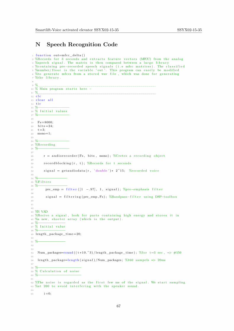
Smartlift-Voice activated elevator SSYX02-15-35 SSYX02-15-35
N Speech Recognition Code
1 f unc t i on out=mfcc_delta ( )2 %Records f o r 3 seconds and ex t r a c t s f e a t u r e ve c t o r s (MFCC) from the analog3 %speech s i g n a l . The matrix i s then compared between a l a r g e l i b r a r y4 %conta in ing pre−recorded speech s i g n a l s ( i . e mfcc matr i ce s ) . The c l a s s i f i e d5 %number/ f l o o r i s the va r i ab l e ’ out ’ . This program can e a s i l y be modi f i ed6 %to generate mfccs from a s to r ed wav f i l e , which was done f o r gene ra t ing7 %the l i b r a r y .8
9 %___________________________________________________________10 % Main program s t a r t s here ~11 %___________________________________________________________12 c l c13 c l e a r a l l14 t i c15 %−−−−−−−−−−−−−−−−16 % I n i t i a l va lue s17 %−−−−−−−−−−−−−−−−18
19 Fs=8000;20 b i t s =24;21 t=3;22 mono=1;23
24 %−−−−−−−−−−−−−−−−25 %Recording26 %−−−−−−−−−−−−−−−−27
28 r = aud io r e co rde r (Fs , b i t s , mono) ; %Cretes a r e co rd ing ob j e c t29
30 r e co rdb l o ck ing ( r , t ) ; %Records f o r t seconds31
32 s i g n a l = getaudiodata ( r , ’ double ’ ) ∗ 2^15; %recorded vo i c e33
34 %−−−−−−−−−−−−−−−35 %F i l t e r s36 %−−−−−−−−−−−−−−−37 pre_emp = f i l t e r ( [ 1 − .97 ] , 1 , s i g n a l ) ; %pre−emphasis f i l t e r38
39 s i g n a l = f i l t e r i n g (pre_emp , Fs ) ; %Bandpass− f i l t e r us ing DSP−too lbox40
41
42
43 %% VAD44 %Recive a s i gna l , look f o r par t s conta in ing high energy and s t o r e s i t in45 %a new , sho r t e r array ( which i s the output ) .46 %−−−−−−−−−−−−−−47 % I n i t i a l va lue48 %−−−−−−−−−−−−−−49 length_package_time=20;50
51 %−−−−−−−−−−−−−−52
53
54 Num_packages=round ( ( t ∗10 .^3) / length_package_time ) ; %f o r t=3 sec , => #15055
56 length_package=length ( s i g n a l ) /Num_packages ; %160 sampels => 20ms57
58 %−−−−−−−−−−−−−−−−−−−−−−59 % Calcu la t i on o f no i s e60 %−−−−−−−−−−−−−−−−−−−−−−61
62 %The no i s e i s regarded as the f i r s t few ms o f the s i g n a l . We s t a r t sampling63 %at 200 to avoid i n t e r f e r i n g with the speaker sound .64
65 i =0;
67
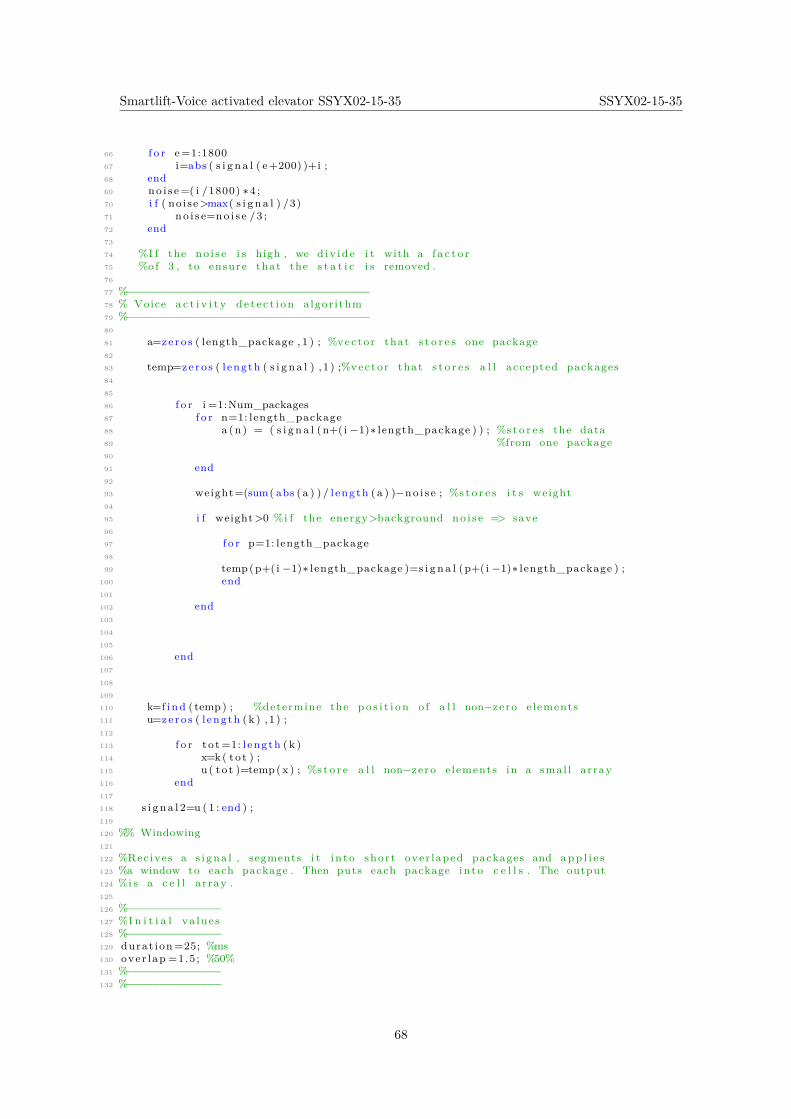
Smartlift-Voice activated elevator SSYX02-15-35 SSYX02-15-35
66 f o r e=1:180067 i=abs ( s i g n a l ( e+200) )+i ;68 end69 no i s e=( i /1800) ∗4 ;70 i f ( no i se>max( s i g n a l ) /3)71 no i s e=no i s e /3 ;72 end73
74 %I f the no i s e i s high , we d iv id e i t with a f a c t o r75 %of 3 , to ensure that the s t a t i c i s removed .76
77 %−−−−−−−−−−−−−−−−−−−−−−−−−−−−−−−−−−−−78 % Voice a c t i v i t y de t e c t i on a lgor i thm79 %−−−−−−−−−−−−−−−−−−−−−−−−−−−−−−−−−−−−80
81 a=ze ro s ( length_package , 1 ) ; %vecto r that s t o r e s one package82
83 temp=ze ro s ( l ength ( s i g n a l ) , 1 ) ;%vecto r that s t o r e s a l l accepted packages84
85
86 f o r i =1:Num_packages87 f o r n=1: length_package88 a (n) = ( s i g n a l (n+( i −1)∗ length_package ) ) ; %s t o r e s the data89 %from one package90
91 end92
93 weight=(sum( abs ( a ) ) / l ength ( a ) )−no i s e ; %s t o r e s i t s weight94
95 i f weight>0 %i f the energy>background no i s e => save96
97 f o r p=1: length_package98
99 temp(p+(i −1)∗ length_package )=s i g n a l (p+( i −1)∗ length_package ) ;100 end101
102 end103
104
105
106 end107
108
109
110 k=f i nd ( temp) ; %determine the po s i t i o n o f a l l non−zero e lements111 u=ze ro s ( l ength (k ) ,1 ) ;112
113 f o r to t =1: l ength (k )114 x=k( to t ) ;115 u( to t )=temp(x ) ; %s t o r e a l l non−zero e lements in a smal l array116 end117
118 s i g n a l 2=u ( 1 : end ) ;119
120 %% Windowing121
122 %Recives a s i gna l , segments i t i n to shor t over laped packages and app l i e s123 %a window to each package . Then puts each package in to c e l l s . The output124 %i s a c e l l array .125
126 %−−−−−−−−−−−−−−127 %I n i t i a l va lue s128 %−−−−−−−−−−−−−−129 durat ion=25; %ms130 over lap =1.5 ; %50%131 %−−−−−−−−−−−−−−132 %−−−−−−−−−−−−−−
68
Smartlift-Voice activated elevator SSYX02-15-35 SSYX02-15-35
133
134 %Makes sure that the l ength o f the s i g n a l d iv ided with t o t a l number o f135 %packges i s an i n t e g e r136 whi le ( c e i l ( l ength ( s i g n a l 2 ) /( round ( ( ( l ength ( s i g n a l 2 ) /Fs ) ∗10 .^3) . . .137 / durat ion ) ) )~=f l o o r ( l ength ( s i g n a l 2 ) /( round ( ( ( l ength ( s i g n a l 2 ) /Fs ) ∗10 .^3) . . .138 / durat ion ) ) ) )139 durat ion=durat ion−1140 i f durat ion < 1141 e r r o r ( ’ f e l i durat ion ’ )142 end143 end144
145 Num_packages=round ( ( ( l ength ( s i g n a l 2 ) /Fs ) ∗10 .^3) / durat ion ) ;146 %Note that t h i s w i l l i n c r e a s e a f t e r the ove r l ap ing proce s s !147
148 length_package=length ( s i g n a l 2 ) /Num_packages ; %This v a r i a b l e i s however149 %f i x ed150
151 %−−−−−−−−−−−−−−−−−−−−−−−−−−−−152 %Overlapping proce s s153 %−−−−−−−−−−−−−−−−−−−−−−−−−−−−154
155 ex tens i on = round ( length_package∗ over lap−length_package ) ; %number o f eleme−156 %ments used as over lap157
158 x=length ( s i g n a l 2 ) / length_package ; %Gives us how many rows we have159 %( f i l l e d and almost f i l l e d )160
161 g=c e i l ( x ) ; %t o t a l rows162 y=f l o o r ( x ) ; %f i l l e d rows163
164 r i g h t=length_package−ex tens i on ;165 J=r i gh t ;166 i =1;167 whi le ( l ength ( s i g n a l 2 )−r i g h t )>length_package168 r i g h t=r i gh t+J ;169 i=i +1;170 end171
172 length_new=i ∗ length_package+( length ( s i g n a l 2 )−r i g h t ) ; %The length o f our173 %padded s i g n a l174
175 dd=c e i l ( length_new/ length_package ) ;176
177 Z=ze ro s (dd , length_package ) ; %empty matrix with best s i z e f o r t h i s vec to r178
179 Z( 1 , 1 : length_package )=s i gna l 2 ( 1 : length_package ) ; %The f i r s t row can be180 %in s e r t e d as i t i s , as i t181 %i s not padded .182
183 S=s i z e (Z) ;184
185 Num_packages=S (1) ;186
187 F=ze ro s (1 , ex tens i on ) ; %Temporary vec to r f o r s t o r i n g the padded elements188 %fo r each row189
190 p=0; %I n i t i a l i z a t i o n o f counter191
192
193
194 f o r i =2:S (1 ) %algor i thm f o r i n s e r t i n g the e lements in c o r r e c t order195
196 f o r u=extens i on :−1:1197
198 F( extens ion−u+1)= s i gna l 2 ( ( length_package−u+1)+(( i −2)∗ . . .199 ( length_package−ex tens i on ) ) ) ;
69
Smartlift-Voice activated elevator SSYX02-15-35 SSYX02-15-35
200 end201 Z( i , 1 : ex t ens i on )=F; %padded elements202
203 t=0;204
205 f o r r=extens i on +1: length_package %o r i g i n a l e lements ( s h i f t e d )206 t=t+1;207 Z( i , r )= s i gna l 2 ( length_package+t+(i −2)∗( length_package−ex tens i on ) ) ;208 p=p+1;209
210
211 i f (p==(length ( s i g n a l 2 )−length_package ) ) %sa f e t y procedure212 break213 end214 end215
216
217 end218
219
220 %−−−−−−−−−−−−−−−−−−−−−−−−−−221 % Windowing proce s s222 %−−−−−−−−−−−−−−−−−−−−−−−−−−223
224 to t = hamming (160) ;225
226 a=ze ro s ( length_package , 1 ) ; %empty vec to r that temporary s t o r e s each package227 C=ze ro s ( length_package , Num_packages ) ;228
229 f o r i =1:Num_packages230 f o r k=1: length_package231
232 a (k )=Z( i , k ) ;233
234 end235
236 window=a .∗ to t ;237
238 C( : , i )=window ;239 end240
241 %−−−−−−−−−−−−−−−−−242 %Power spectrum243 %−−−−−−−−−−−−−−−−−244 N=512;245 [ one , two]= s i z e (C) ;246
247 temp=ze ro s (N, two ) ;248 f o r i =1:two249
250 y=f f t ( (C( : , i ) ) ,N) ; %f f t o f one c e l l251 temp ( : , i )= r e a l ( y .∗ conj ( y ) /N) ; %the power252
253 end254
255
256 %%257 %−−−−−−−−−−−−−−258 % Fi l t e rbank259 %−−−−−−−−−−−−−−−260 %Creates the f i l t e r b a n k t r i a n gu l a r windows261
262 Num_fi lters=26;263
264 K=N/2 ;265
266
70
Smartlift-Voice activated elevator SSYX02-15-35 SSYX02-15-35
267 %Al l the f o l l ow i n g v a r i a b l e s are in [Hz ]268 Range=[300 3 400 ] ;269 Min = 0 ;270 Low = Range (1 ) ;271 High = Range (2 ) ;272 Max = 0.5∗Fs ;273 F = l i n s p a c e (Min ,Max,K) ;274
275 % Determine the s t a r t and end po s i t i o n s f o r each f i l t e r in the276 % frequency spectrum277 po s i t i o n s = f r e q ( mel (Low) +[0: Num_fi lters +1]∗((mel (High )−mel (Low) ) / . . .278 ( Num_fi lters+1) ) ) ;279
280
281 H = ze ro s ( Num_filters , K ) ; %Matrix to s t o r e the f i l t e r data in282 UH= ze ro s ( Num_filters , K ) ;283 f o r m = 1 : Num_fi lters %Creates each f i l t e r s e p e r a t l y284
285 P=ze ro s (1 , l ength (F) ) ; %vec to r that w i l l s t o r e a l l the f r e q286 %po s i t i o n s between two elements in ’ po s i t i on s ’287
288
289 f o r p=1: l ength (F) %In t h i s case we look between each f i l t e r s290 %s t a r t and middle po s i t i on , i . e the r a i s i n g291 %s id e o f the t r i ang .292 i f F(p)>=po s i t i o n s (m) && F(p)<=po s i t i o n s (m+1)293 P(p)=1;294 end295 end296 pp=f i nd (P) ; %Finds which e lements are none−zero297
298 H(m, pp) = (F(pp)−po s i t i o n s (m) ) / ( ( p o s i t i o n s (m+2)−po s i t i o n s (m) ) . . .299 ∗( p o s i t i o n s (m+1)−po s i t i o n s (m) ) ) ; %f i nd s the cor re spond ing300 %y−value f o r each P.301
302
303 P=ze ro s (1 , l ength (F) ) ;304 f o r p=1: l ength (F) %In t h i s case we look between each f i l t e r s305 %middle and end pos i t i on , i . e the dec rea ing306 %s id e o f the t r i ang .307 i f F(p)>=po s i t i o n s (m+1) && F(p)<=po s i t i o n s (m+2)308 P(p)=1;309 end310 end311 pp=f i nd (P) ;312
313
314 H(m, pp) = ( p o s i t i o n s (m+2)−F(pp) ) / ( ( p o s i t i o n s (m+2)−po s i t i o n s (m) ) . . .315 ∗( p o s i t i o n s (m+2)−po s i t i o n s (m+1) ) ) ;316 end317 H = H./ repmat (max(H, [ ] , 2 ) ,1 ,K) ; %normal ize to 1318
319 vec to r=H;320
321
322 %% Calcu la te F i l t e rbank Energ i e s from prev ious data323
324 Output=vecto r ∗ temp ( 1 :K, : ) ; %Where temp i s the powerspec r e s u l t s325
326 % L i f t i n g :327 Num_mfcc=13; %Number o f MFCCs regarded328 LP=22;329
330
331 l i f t e r = expander ( Num_mfcc , LP ) ; %see func t i on below332 LOG = log (Output ) ; %Logarithmic333 DCT=ICT( Num_mfcc , Num_fi lters ) ; %See func t i on below
71
Smartlift-Voice activated elevator SSYX02-15-35 SSYX02-15-35
334 DCT=DCT∗LOG;335 DCT_lift=diag ( l i f t e r ) ∗DCT;336 DCT_lift ( 1 , : ) = [ ] ; % Removes f i r s t row ( r ep r e s en t s whole energy )337
338 Final_matrix=DCT_lift ;339
340 %% de l t a s341
342 to t =9; %Number o f mfccs taken in to c on s i d e r a t i on343 [Q,E] = s i z e ( Final_matrix ) ;344 f l o o r = f l o o r ( to t /2) ;345 to t = 2∗ f l o o r + 1 ;346 win = f l o o r :−1:− f l o o r ;347
348 xx = [ repmat ( Final_matrix ( : , 1 ) ,1 , f l o o r ) , Final_matrix , repmat . . .349 ( Final_matrix ( : , end ) ,1 , f l o o r ) ] ;350 % The mfcc ar rays are padded351
352 f i l t = f i l t e r (win , 1 , xx , [ ] , 2) ;353
354 Delta = f i l t ( : , 2 ∗ f l o o r + [ 1 :E ] ) ;355
356 %Courtesy o f Danie l P . W. E l l i s357 % http :// l ab ro sa . ee . columbia . edu/matlab/ rastamat / d e l t a s .m358
359 %% Turn 2 %same as above but with other to t .360
361 to t =5;362 f l o o r = f l o o r ( to t /2) ;363 to t = 2∗ f l o o r + 1 ;364 win = f l o o r :−1:− f l o o r ;365 xx = [ repmat ( Final_matrix ( : , 1 ) ,1 , f l o o r ) , Final_matrix , repmat . . .366 ( Final_matrix ( : , end ) ,1 , f l o o r ) ] ;367 f i l t = f i l t e r (win , 1 , xx , [ ] , 2) ;368 Delta_store = f i l t ( : , 2 ∗ f l o o r + [ 1 :E ] ) ;369 %% ac c e l e r a t i o n %ca l cu l a t ed same as above but with x = Delta_store .370 to t =5;371 [Q,E] = s i z e ( Delta_store ) ;372 f l o o r = f l o o r ( to t /2) ;373 to t = 2∗ f l o o r + 1 ;374 win = f l o o r :−1:− f l o o r ;375 xx = [ repmat ( Delta_store ( : , 1 ) ,1 , f l o o r ) , Delta_store , repmat . . .376 ( Delta_store ( : , end ) ,1 , f l o o r ) ] ;377 f i l t = f i l t e r (win , 1 , xx , [ ] , 2) ;378 Delta2 = f i l t ( : , 2 ∗ f l o o r + [ 1 :E ] ) ;379
380 %% Fina l r e s u l t381
382 Final_matrix=[Final_matrix ; Delta ; Delta2 ] ; %these are the ext rac t ed383 %f e a t u r e s384 r=so r t i n g2 ( Final_matrix ) ;385 % s t r =[ ’ Des i red f l o o r i s ’ , num2str ( r ) ] ; %Uncomment when running here386 % disp ( s t r )387
388 out=r ; %The de s i r ed f l o o r389
390 end391
392
393 f unc t i on Number=so r t i n g2 ( vec to r )394
395 BIB=12; %number o f r e c o rd i ng s f o r each number396
397 temp=ze ro s (BIB , 1 0 ) ;398
399 f o r w=1:10400 f o r t=1:BIB
72
Smartlift-Voice activated elevator SSYX02-15-35 SSYX02-15-35
401 n=t+9;402 V=st ru c t 2a r r ay ( load ( s p r i n t f ( ’%d%d .mat ’ ,w, n) ) ) ; %loads the l i b r a r y403
404
405 Minimun_d_map = map_d( abs (V) , abs ( vec to r ) ) ;406 [ p , q ,C] = dtw_calc(1−Minimun_d_map) ;407
408 %Functions map_d and dtw_calc cour te sy o f Danie l P . W. E l l i s . . .409 %(Dynamic Time Warp in Matlab , Copyright (C) 2003) .410
411
412
413 A=C( s i z e (C, 1 ) , s i z e (C, 2 ) ) ; %The corner va lue o f the l i n e r ep r e s en t s414 %the t o t a l t r a v e l co s t .415
416 temp( t ,w)=A; %Store s each comparinson417
418 end419 end420
421 [ a , b]= f i nd ( temp==min( temp ( : ) ) ) ; %f i n d s the minimum value and p r i n t s i t s422 %po s i t i o n ( i . e f l o o r number )423
424
425 Number=b ;426
427 end428
429
430
431 f unc t i on out_mel = mel (Hz)432 out_mel=(1000/ log10 (2 ) ∗ l og10 (1+Hz/1000) ) ;433 end434
435 f unc t i on out_freq = f r e q (Mel )436 out_freq =(1000∗(2 .^(Mel /1000)−1) ) ;437 end438
439 f unc t i on out = expander ( Num_mfcc , LP)440 out = ( 1+0.5∗LP∗ s i n ( p i ∗ [ 0 :Num_mfcc−1]/LP) ) ;441 end442
443 f unc t i on out = ICT(Num_mfcc , Num_fi lters )444 out= ( sq r t ( 2 . 0/ Num_fi lters ) ∗ . . .445 cos ( repmat ( [ 0 : Num_mfcc−1 ] . ’ , 1 , Num_fi lters ) .∗ . . .446 repmat ( p i ∗ ( [ 1 : Num_fi lters ] −0.5) /Num_filters ,Num_mfcc , 1 ) ) ) ;447 end
73