Embed Size (px)
Citation preview
1
Group Members:
Aezaz Ali 160644
Zubair Bin Hamid 160564
Smart Parking System for Air University
Bachelor of Science in Computer Science
Supervisor: Dr. Naveed Anwar Bhatti
Department of Computer Science
Air University, Islamabad
May 2020

2
©Aezaz Ali, 2020
3
Certificate
We accept the work contained in the report titled “Smart Parking System for Air University”,
written by Mr. Aezaz Ali and Mr. Zubair Bin Hamid as a confirmation to the required Standard
for the partial fulfillment of the degree of Bachelor of Science in Computer Science.
Approved by:
Supervisor:
---------------------------------------------------------------------------
Internal Examiner:
---------------------------------------------------------------------------
External Examiner:
---------------------------------------------------------------------------
Head of the Department:
--------------------------------------------------------------------------
June 2020

4
5
Abstract
The main idea of the Smart Parking System for Air University (SPARKAU) is to provide
a way for drivers to park their cars with more ease. It is said that “Time is money” so everyone
gets frustrated when they give their time and effort in return for nothing. In basic parking systems,
there is no check and balance for the available slots. The driver starts looking for the free parking
slot by the hit and tries method if he manages to find a parking slot available, it is a lucky try but
on the contrary, most of the time driver does not find a slot available. He returns from the parking
with aggression and frustration. It wastes the fuel as well as the time of the driver. People facing
this problem becomes very irritated because of the necessity to use parking daily. This problem
also correlates with the parking area of Air University. Whenever the driver enters the university
premises, he looks for the parking area to park his car, but it often results in time and fuel wastage.
The driver examines the whole parking area but does not find a single slot available to park his
car. It becomes very annoying when the driver exits from another side of parking without parking
his car.
Our system will save both time and fuel of the driver. It will help the drivers to park their
cars in the parking space available. The driver would not have to waste his time looking for every
parking slot. He can acknowledge the availability of the slot by just using our software. The driver
will open the web application of SPARKAU, search for the most suitable free parking space, and
easily park his car. This system is very different from hardware-based methods because it saves
the installation as well as the maintenance cost of hardware. In the hardware-based smart parking
systems, sensors are installed in the parking areas. Microcontrollers are used to check the flow of
parking and updating the availability of the free slot. This system requires hardware but its
installation and maintenance is a budget problem.
In our situation, the university parking had already deployed CCTV cameras for security
purposes. We used these cameras as a source of input for our software, process the input on our
algorithm, and provide the user with a website having the information about free space available.
6
Whenever a car enters or leaves the parking, the CCTV cameras are recording the videos
continuously. Our software will use these videos. On the server-side, when our software takes the
input, it processes the videos and calculates the newly available and occupied parking slots.
Whenever a change in the parking slot occurs. A request is sent to update the database. While on
the client-side, an API service is running continuously, which asks for the new data from the
database. Whenever the database is updated, the new data is sent as an API response. The response
then updates the web application about the newly available parking slots.
7
Acknowledgments
We want to thanks Allah Almighty for giving us the ability to complete our research.
We want to express our deepest appreciation to our supervisor Dr. Naveed Anwar Bhatti for
helping and guiding us throughout this project.
Special thanks to families and friends for their unconditional love and support for us.
We also want to express love and gratitude towards our parents and siblings without whom it
would have been impossible to be here.
Aezaz Ali
Islamabad, Pakistan
June 2020

8
“Every problem has a solution. You just
have to be creative enough to find it”
Travis Kalanick
9
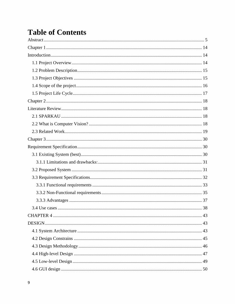
Table of Contents Abstract ........................................................................................................................................... 5
Chapter 1 ....................................................................................................................................... 14
Introduction ................................................................................................................................... 14
1.1 Project Overview ................................................................................................................. 14
1.2 Problem Description ............................................................................................................ 15
1.3 Project Objectives ............................................................................................................... 15
1.4 Scope of the project ............................................................................................................. 16
1.5 Project Life Cycle................................................................................................................ 17
Chapter 2 ....................................................................................................................................... 18
Literature Review.......................................................................................................................... 18
2.1 SPARKAU .......................................................................................................................... 18
2.2 What is Computer Vision? .................................................................................................. 18
2.3 Related Work....................................................................................................................... 19
Chapter 3 ....................................................................................................................................... 30
Requirement Specification ............................................................................................................ 30
3.1 Existing System (best) ......................................................................................................... 30
3.1.1 Limitations and drawbacks: .......................................................................................... 31
3.2 Proposed System ................................................................................................................. 31
3.3 Requirement Specifications................................................................................................. 32
3.3.1 Functional requirements ............................................................................................... 33
3.3.2 Non-Functional requirements ....................................................................................... 35
3.3.3 Advantages ................................................................................................................... 37
3.4 Use cases ............................................................................................................................. 38
CHAPTER 4 ................................................................................................................................. 43
DESIGN ........................................................................................................................................ 43
4.1 System Architecture ............................................................................................................ 43
4.2 Design Constrains ............................................................................................................... 45
4.3 Design Methodology ........................................................................................................... 46
4.4 High-level Design ............................................................................................................... 47
4.5 Low-level Design ................................................................................................................ 49
4.6 GUI design .......................................................................................................................... 50
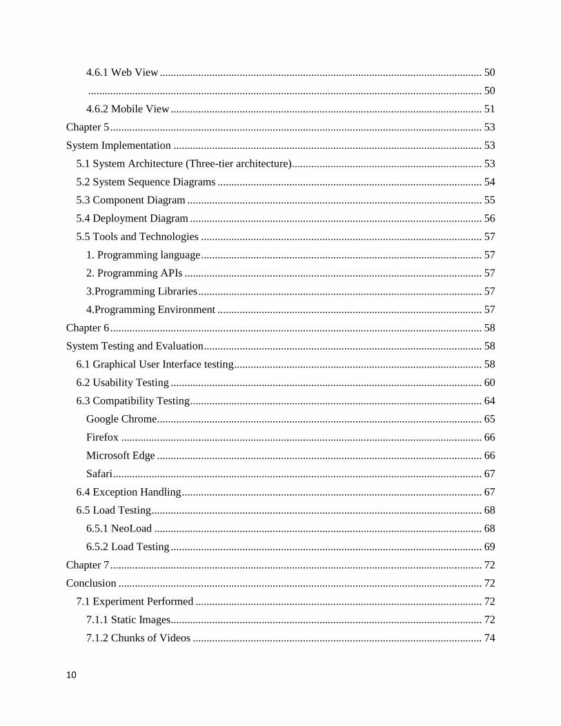
10
4.6.1 Web View ..................................................................................................................... 50
............................................................................................................................................... 50
4.6.2 Mobile View ................................................................................................................. 51
Chapter 5 ....................................................................................................................................... 53
System Implementation ................................................................................................................ 53
5.1 System Architecture (Three-tier architecture) ..................................................................... 53
5.2 System Sequence Diagrams ................................................................................................ 54
5.3 Component Diagram ........................................................................................................... 55
5.4 Deployment Diagram .......................................................................................................... 56
5.5 Tools and Technologies ...................................................................................................... 57
1. Programming language ...................................................................................................... 57
2. Programming APIs ............................................................................................................ 57
3.Programming Libraries ....................................................................................................... 57
4.Programming Environment ................................................................................................ 57
Chapter 6 ....................................................................................................................................... 58
System Testing and Evaluation ..................................................................................................... 58
6.1 Graphical User Interface testing .......................................................................................... 58
6.2 Usability Testing ................................................................................................................. 60
6.3 Compatibility Testing .......................................................................................................... 64
Google Chrome...................................................................................................................... 65
Firefox ................................................................................................................................... 66
Microsoft Edge ...................................................................................................................... 66
Safari ...................................................................................................................................... 67
6.4 Exception Handling ............................................................................................................. 67
6.5 Load Testing ........................................................................................................................ 68
6.5.1 NeoLoad ....................................................................................................................... 68
6.5.2 Load Testing ................................................................................................................. 69
Chapter 7 ....................................................................................................................................... 72
Conclusion .................................................................................................................................... 72
7.1 Experiment Performed ........................................................................................................ 72
7.1.1 Static Images................................................................................................................. 72
7.1.2 Chunks of Videos ......................................................................................................... 74
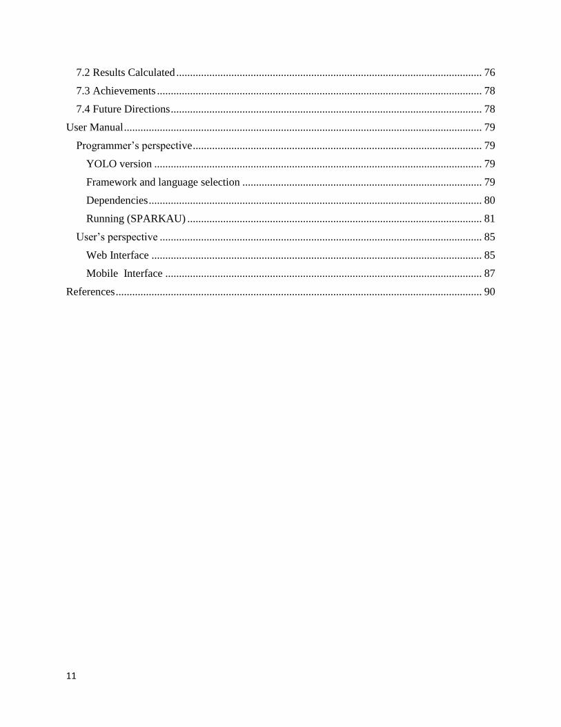
11
7.2 Results Calculated ............................................................................................................... 76
7.3 Achievements ...................................................................................................................... 78
7.4 Future Directions ................................................................................................................. 78
User Manual .................................................................................................................................. 79
Programmer’s perspective ......................................................................................................... 79
YOLO version ....................................................................................................................... 79
Framework and language selection ....................................................................................... 79
Dependencies ......................................................................................................................... 80
Running (SPARKAU) ........................................................................................................... 81
User’s perspective ..................................................................................................................... 85
Web Interface ........................................................................................................................ 85
Mobile Interface ................................................................................................................... 87
References ..................................................................................................................................... 90
12
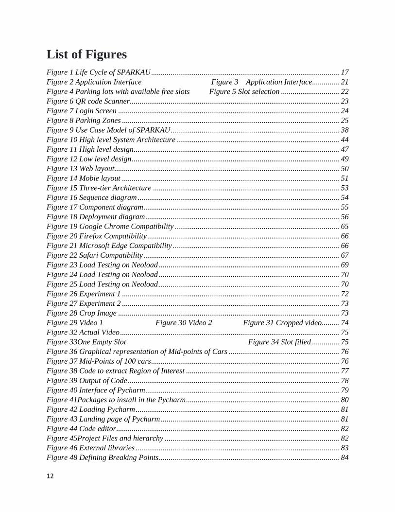
List of Figures
Figure 1 Life Cycle of SPARKAU ................................................................................................. 17
Figure 2 Application Interface Figure 3 Application Interface.............. 21
Figure 4 Parking lots with available free slots Figure 5 Slot selection .............................. 22
Figure 6 QR code Scanner ............................................................................................................ 23
Figure 7 Login Screen .................................................................................................................. 24
Figure 8 Parking Zones ................................................................................................................ 25
Figure 9 Use Case Model of SPARKAU ....................................................................................... 38
Figure 10 High level System Architecture .................................................................................... 44
Figure 11 High level design .......................................................................................................... 47
Figure 12 Low level design ........................................................................................................... 49
Figure 13 Web layout.................................................................................................................... 50
Figure 14 Mobie layout ................................................................................................................ 51
Figure 15 Three-tier Architecture ................................................................................................ 53
Figure 16 Sequence diagram ........................................................................................................ 54
Figure 17 Component diagram ..................................................................................................... 55
Figure 18 Deployment diagram .................................................................................................... 56
Figure 19 Google Chrome Compatibility ..................................................................................... 65
Figure 20 Firefox Compatibility ................................................................................................... 66
Figure 21 Microsoft Edge Compatibility ...................................................................................... 66
Figure 22 Safari Compatibility ..................................................................................................... 67
Figure 23 Load Testing on Neoload ............................................................................................. 69
Figure 24 Load Testing on Neoload ............................................................................................. 70
Figure 25 Load Testing on Neoload ............................................................................................. 70
Figure 26 Experiment 1 ................................................................................................................ 72
Figure 27 Experiment 2 ................................................................................................................ 73
Figure 28 Crop Image .................................................................................................................. 73
Figure 29 Video 1 Figure 30 Video 2 Figure 31 Cropped video ......... 74
Figure 32 Actual Video ................................................................................................................. 75
Figure 33One Empty Slot Figure 34 Slot filled .............. 75
Figure 36 Graphical representation of Mid-points of Cars ......................................................... 76
Figure 37 Mid-Points of 100 cars ................................................................................................. 76
Figure 38 Code to extract Region of Interest ............................................................................... 77
Figure 39 Output of Code ............................................................................................................. 78
Figure 40 Interface of Pycharm .................................................................................................... 79
Figure 41Packages to install in the Pycharm ............................................................................... 80
Figure 42 Loading Pycharm ......................................................................................................... 81
Figure 43 Landing page of Pycharm ............................................................................................ 81
Figure 44 Code editor ................................................................................................................... 82
Figure 45Project Files and hierarchy .......................................................................................... 82
Figure 46 External libraries ......................................................................................................... 83
Figure 48 Defining Breaking Points ............................................................................................. 84
13
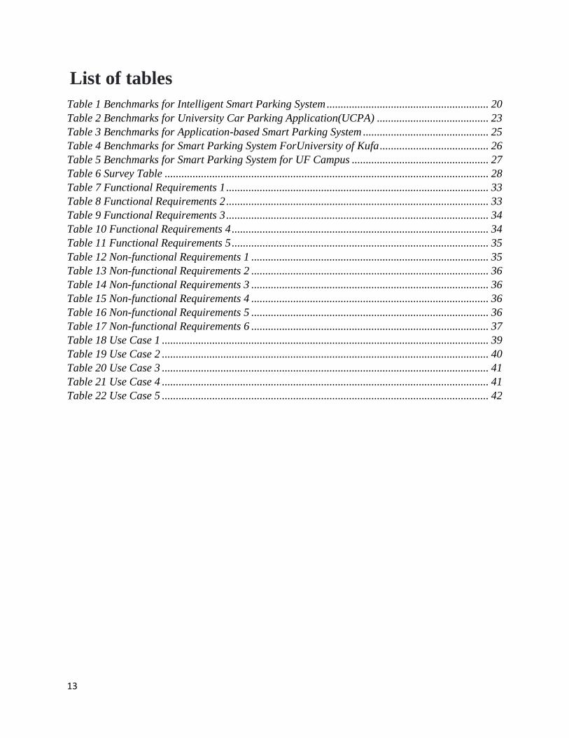
List of tables
Table 1 Benchmarks for Intelligent Smart Parking System .......................................................... 20
Table 2 Benchmarks for University Car Parking Application(UCPA) ........................................ 23
Table 3 Benchmarks for Application-based Smart Parking System ............................................. 25
Table 4 Benchmarks for Smart Parking System ForUniversity of Kufa ....................................... 26
Table 5 Benchmarks for Smart Parking System for UF Campus ................................................. 27
Table 6 Survey Table .................................................................................................................... 28
Table 7 Functional Requirements 1 .............................................................................................. 33
Table 8 Functional Requirements 2 .............................................................................................. 33
Table 9 Functional Requirements 3 .............................................................................................. 34
Table 10 Functional Requirements 4 ............................................................................................ 34
Table 11 Functional Requirements 5 ............................................................................................ 35
Table 12 Non-functional Requirements 1 ..................................................................................... 35
Table 13 Non-functional Requirements 2 ..................................................................................... 36
Table 14 Non-functional Requirements 3 ..................................................................................... 36
Table 15 Non-functional Requirements 4 ..................................................................................... 36
Table 16 Non-functional Requirements 5 ..................................................................................... 36
Table 17 Non-functional Requirements 6 ..................................................................................... 37
Table 18 Use Case 1 ..................................................................................................................... 39
Table 19 Use Case 2 ..................................................................................................................... 40
Table 20 Use Case 3 ..................................................................................................................... 41
Table 21 Use Case 4 ..................................................................................................................... 41
Table 22 Use Case 5 ..................................................................................................................... 42
14
Chapter 1
Introduction
This chapter contains all the fundamental information about the Smart Parking system for
Air University (SPARKAU). It contains the basic motivation for planning this project. It explains
the basic smart parking systems, the types of smart parking systems, and our smart parking system.
It includes the limitations, objectives, and life cycle of our project.
1.1 Project Overview
Due to an increase in the number of departments in our university, parking problems are
bound to exist alongside. The development of departments increases the number of students and
faculty members in the university. It results in too many vehicles inside the university. More
vehicles on the campus result in added problems associated with the parking area of the university.
The parking area gets crowded with vehicles. The driver cannot tell whether he will find an
available free slot.
Smart parking is a software and hardware-based system in which the system guides the
user about the availability of the parking. Whenever the user enters the parking, he takes a guide
by the system for the vacant car slots. Smart parking is a very efficient parking tool that is used in
various foreign countries.
There are two types of smart parking systems, which guide the users about the free parking
slots. One of them is a hardware-dependent sensor-based smart parking system while the other one
is a software-based system. The smart parking system based on IoT sensors (hardware) is
commonly used in the parking areas of the building. Most of the buildings have the parking area
in the basement of the building. It is preferable to guide the user so that he knows whether the
parking is available or not. The LED screen or LCD screen is put up at the entrance to guide the
user about parking.
In the software-based smart parking system, users have a certain application or a website
to look for parking. He can examine the parking area to find a free slot using the application or
15
website. In most cases, Open space parking like universities, offices, or parks has software-based
smart parking systems.
Smart Parking System for Air University also known as SPARKAU is a software-based
smart parking system that helps the members of our university to park their cars easily and
properly. It is developed according to the parking area of the university. Whenever a person enters
the university, the first thing that blinks in his mind is to find a free parking slot closest to his
department. He can look for the available slots with our smart parking system. The user can access
the web or mobile web interface of SPARKAU using the mobile phone or tablet. He can analyze
the different parking zones for the available free slot. He can examine the parking zones to find
the nearest free parking slot with his department.
1.2 Problem Description
When the university initiated the step of developing new departments on the campus, the
total sum of university members also increased. More people in the university results in more
vehicles in the university. The parking area of the university gets filled up with cars. It is
impossible to tell about the availability of the free parking slot without examining the parking area.
The daily routine of looking for free slots is time wastage and fuel wastage.
Smart parking is the key idea to efficiently utilize the parking system. The user will be able
to look for the free slot without wasting a minute. By using SPARKAU, the user will not feel the
frustration and annoyance of roaming around to find a proper slot for parking. It will save a lot of
time for the user. Another advantage would be the reduction of useless burning of fuel of the user’s
car.
1.3 Project Objectives
SPARKAU will turn out to be a time-saver application. It will help many university
members in the coming days. Students, faculty members, and admin members of our university
will use it. The key objectives of this project are
To help the people of our university to find a free parking slot
To solve the daily routine issue of looking for free slots.
To make the CCTV cameras used more efficiently by using them as the main input source
of this project.
16
To save the time and fuel of university members
To help the university members get rid of this useless frustration caused by the parking
problem.
To research on computer vision and enhance our knowledge.
1.4 Scope of the project
SPARKAU will consist of a front-end web application and a backend-python code server.
Web Application will be responsible for handling both the mobile view and the table view. It will
display the parking slots contained in different zones Each zone represents a specific parking area.
The web interface will consist of four zones displaying different areas of parking. Each zone will
cover at least 5-10 parking slots. The range is not specific because our parking does not have any
CCTV cameras to cover the right side lane view except the one moving camera. The python code
server will use a Computer Vision algorithm Called YOLO [2] (you only look once: An image
classification algorithm) for backend processing. However, there are some issues shown by YOLO
when used for our parking area. These issues are;
The CCTV cameras are fitted sidewise and tilted which generates a tilted view of the
parking
The cars hidden behind the car cannot be classified
YOLO sometimes confuses to differentiate between two cars because of an inappropriate
car parked
YOLO could not classify the objects whose edges are not well defined and apart from other
objects
Some of these limitations are hardware-based which are out of the scope of this project,
e.g. CCTV camera is fitted sidewise. It is very difficult for YOLO to detect all the cars with side
angle images. One of the other limitations is the inappropriate parking of cars, which is again out
of scope for this project.
Some other issues are the placement of CCTV cameras in the unive9p[srsity Parking. As
the CCTV cameras were already deployed by our university admin.so it was out of the scope of
the project. Other issues include having rainy days which results in blur views, night views, big
trucks or cars in front of small cars, and fewer cameras to cover the parking area.
17
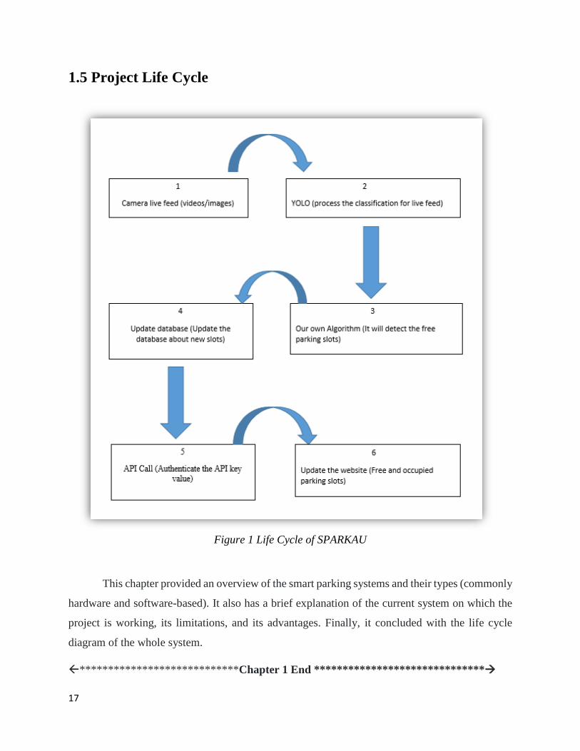
1.5 Project Life Cycle
Figure 1 Life Cycle of SPARKAU
This chapter provided an overview of the smart parking systems and their types (commonly
hardware and software-based). It also has a brief explanation of the current system on which the
project is working, its limitations, and its advantages. Finally, it concluded with the life cycle
diagram of the whole system.
****************************Chapter 1 End ******************************
18
Chapter 2
Literature Review This chapter explains a few of the smart parking applications along with their method of
working. The paragraphs given below have a very brief summary of the basic methodology of
these applications. The survey table has all the features that can be examined based on the study
of these applications. Finally, this chapter includes all the problems within the existing systems.
2.1 SPARKAU
SPARKAU is a computer vision-based Smart Parking System (SPS) in which the system
will classify the cars through the videos/images from already deployed CCTV cameras in the
parking area. From the information extracted, it will detect the availability of free slots. It will then
update the user interface about the availability of free parking slots. The user interface is a front-
end website/ mobile web App.
SPARKAU is divided into two sub-components. One of them is the Computer vision-based
backend python code, which will do all the backend difficult work processing, while the other one
is the front-end website which will be used to display the parking slots.
2.2 What is Computer Vision?
Computer vision is a disciplinary scientific field that deals with how computers can gain
a high-level understanding of digital images or videos [3]. It is a very vast field in computer
science. Various projects around the globe being developed are purely in computer vision such as
parking systems, auto-driving vehicles, self-driving drones, etc.
In Computer vision, the algorithm is trained on images having labels on it so it can
recognize every pixel and the features of the image. Therefore, the algorithm remembers those
features for that class. When training is completed, the algorithm is being tested and validated
whether it recognizes the image or not. Most of the algorithms are considered to be good if their
accuracy is high up to 80%.
Computer Vision is used in various fields such as automatic driving vehicles for disabled
people, surveillance robots for security purposes, text scanner for converting the image text into
19
the editable form, health care medical centers for diagnosing of cancers and other diseases, in
laboratories for making antidotes of disease, etc.
2.3 Related Work
Every year, many universities are developed around the globe. Most of the universities tend
to enhance their ranking by developing new departments, labs, and buildings. The growth of these
factors increases the overall population of students, faculty, and staff members inside the
university. With decreasing parking supply and increasing enrollments and faculty and staff
members, universities are beginning to realize the importance of properly allocating available
parking [4].
Intelligent Parking System (IPS) is a smart parking system that was developed for the
University of Texas at Austin in the year 2003. Information about the parking slots can be given
to the drivers by the use of IPS. IPS reduces the congestion in parking areas, insufficient utilization
of the available parking, and road congestion caused by searching for free slots [4]. IPS works
with the help of the variable message sign (VMS), which serves as a “wayfinding” device.
Wayfinding means providing information about the path to free parking slots. IPS system operates
using loop detectors, ticket splitters, and cash registers as vehicle counting equipment located at
each garage or parking. A controller interface is also required since the equipment is not capable
of calculating a “space available” number. This interface counts and calculates space availability
in real-time as each car enters or exits the parking. This number count is transmitted via modem
to a central computer. The central computer then sends the required signal along to the variable
message signs with the help of Microsoft-based Ramp Management Software. The operator can
control the system from the central computer at any time. He can read and modify sign messages,
correct parameters, check the state of an entire mounted electronic sign mast or parking facility,
and can take appropriate action as required. The below given are the benchmarks for the Intelligent
Parking System.
Programming language Html,asp.NET
Responsive yes
Performance real-time information travel
Hardware included Yes
20
ML algorithm No
Table 1 Benchmarks for Intelligent Smart Parking System
IPS system consists of a server page that can control the parameters, messages being
displayed on variable message signs, LED screens, parking counts, and all the systems. The server
page will get the information and it will update the HTML view in real-time. Whenever the user
presses the refresh button on the website. The script will update the web page and the user will be
able to see the availability of parking on the web browser. Intelligent Parking System will consist
of an HTML web page for the user. The web page will respond according to the resolution of the
user’s device.
The performance of the Intelligent Parking system is very accurate and good. It informs
the users about the availability of free parking in real-time. It updates the web page as soon as the
user presses the refresh button.
The intelligent parking system mostly contains hardware-based components. The VMS
system, LED displays, the modem used for signal transferring to the main computer, ticket
splitters, and gate arms.
There is no Machine-learning algorithm included in this project as it simply extracts
information from hardware. Most of the software part is a simple web page that displays the
availability of parking.
Parking may seem a trivial matter, but it is a serious problem for many students. Smart
Parking Systems(SPSs) disseminate real-time parking spot availability to drivers searching for
parking[5]. Generally, various SPS applications are available for shopping malls or airports.
Sensors and parking meters are commonly used in these applications to analyze the availability of
parking slots. Parking meters are considered to be inaccurate in examining the available parking
slot while on the contrary, sensors are a good option to develop an accurate SPS application. But
sensors have disadvantages to embed in open parking spaces because of weather conditions.
One of the other applications is University Car Parking Application (UCPA) developed
by Chinmayee Lingman (2018) in University-Corpus Christi, Corpus Christi, Texas[6].In UCPA,
the driver would have an application that would serve as a parking slot guidance. A map of the
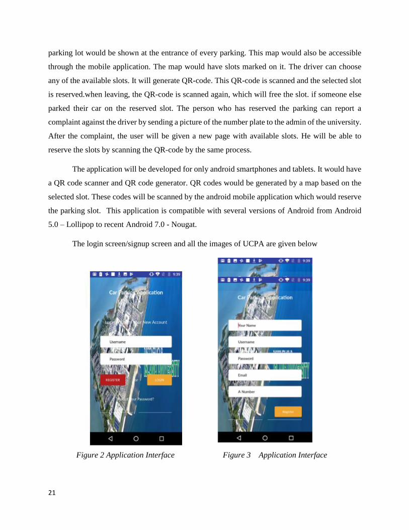
21
parking lot would be shown at the entrance of every parking. This map would also be accessible
through the mobile application. The map would have slots marked on it. The driver can choose
any of the available slots. It will generate QR-code. This QR-code is scanned and the selected slot
is reserved.when leaving, the QR-code is scanned again, which will free the slot. if someone else
parked their car on the reserved slot. The person who has reserved the parking can report a
complaint against the driver by sending a picture of the number plate to the admin of the university.
After the complaint, the user will be given a new page with available slots. He will be able to
reserve the slots by scanning the QR-code by the same process.
The application will be developed for only android smartphones and tablets. It would have
a QR code scanner and QR code generator. QR codes would be generated by a map based on the
selected slot. These codes will be scanned by the android mobile application which would reserve
the parking slot. This application is compatible with several versions of Android from Android
5.0 – Lollipop to recent Android 7.0 - Nougat.
The login screen/signup screen and all the images of UCPA are given below
Figure 2 Application Interface Figure 3 Application Interface
22
The first screen is the login screen in the Application. It will ask the user to enter its
credentials. If the user has not yet registered, then the user would click the register button and the
registration screen will pop up. It will ask the user for its personal information. After complete
registration, the user would be able to use this application.
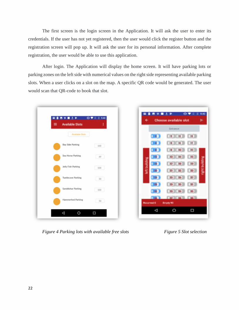
After login. The Application will display the home screen. It will have parking lots or
parking zones on the left side with numerical values on the right side representing available parking
slots. When a user clicks on a slot on the map. A specific QR code would be generated. The user
would scan that QR-code to book that slot.
Figure 4 Parking lots with available free slots Figure 5 Slot selection
23
Figure 6 QR code Scanner
Programming language Java,Xaml,Json
Responsive Yes
Performance Based on reservation
Hardware included No
ML algorithm No
Table 2 Benchmarks for University Car Parking Application(UCPA)
The main focus of this application is the android platform. The languages used for android
mobile development are Xaml and Java. QR code scanners and QR code generators will be
developed in java. It will also have a centralized database. The database will be implemented in
the firebase. The response will be based on the reservation time of a driver. It is a purely software-
based product. There is no hardware included in this product. It is also a non-machine learning
product.
IoT(Internet of things) is the newly emerging technology of the modern era. With the
advancement in technology, it has become very easy to collect an enormous amount of data for
experimental purposes. Multiple solutions exist to the problem of finding parking space
availability. They are broadly classified into Vision-Based approaches and Sensor-Based
approaches[8].
24
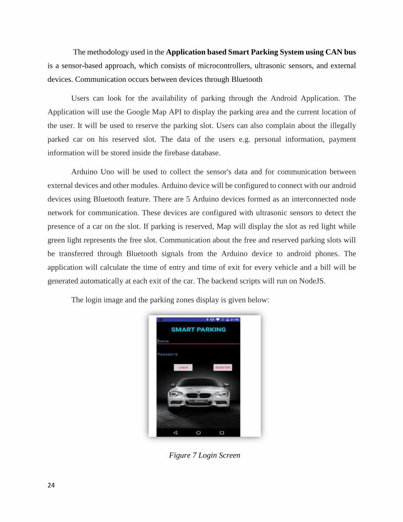
The methodology used in the Application based Smart Parking System using CAN bus
is a sensor-based approach, which consists of microcontrollers, ultrasonic sensors, and external
devices. Communication occurs between devices through Bluetooth
Users can look for the availability of parking through the Android Application. The
Application will use the Google Map API to display the parking area and the current location of
the user. It will be used to reserve the parking slot. Users can also complain about the illegally
parked car on his reserved slot. The data of the users e.g. personal information, payment
information will be stored inside the firebase database.
Arduino Uno will be used to collect the sensor's data and for communication between
external devices and other modules. Arduino device will be configured to connect with our android
devices using Bluetooth feature. There are 5 Arduino devices formed as an interconnected node
network for communication. These devices are configured with ultrasonic sensors to detect the
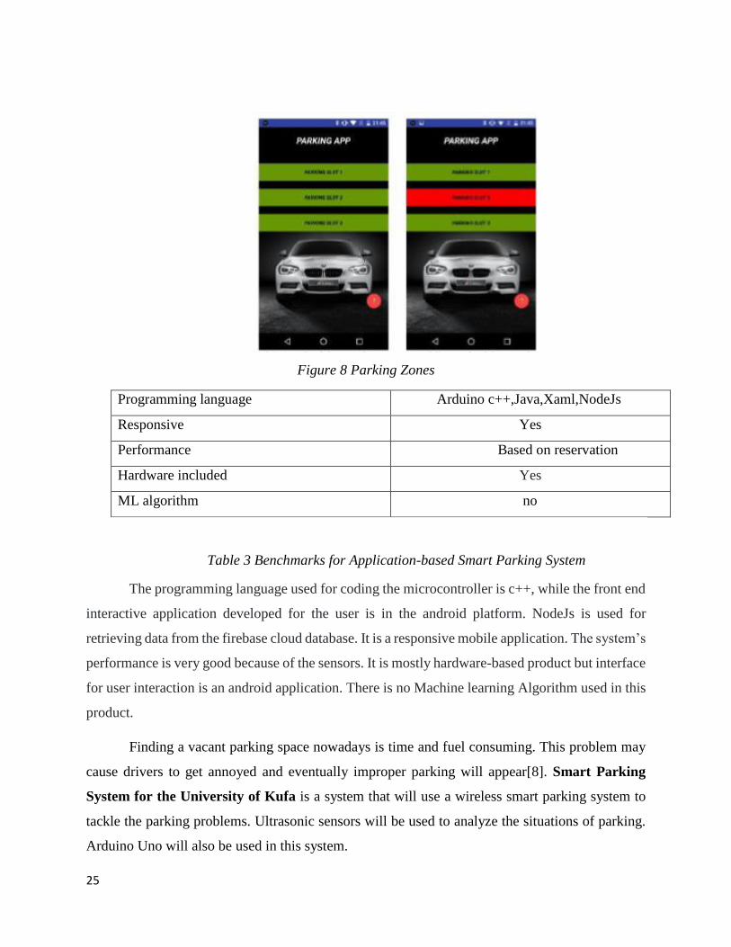
presence of a car on the slot. If parking is reserved, Map will display the slot as red light while
green light represents the free slot. Communication about the free and reserved parking slots will
be transferred through Bluetooth signals from the Arduino device to android phones. The
application will calculate the time of entry and time of exit for every vehicle and a bill will be
generated automatically at each exit of the car. The backend scripts will run on NodeJS.
The login image and the parking zones display is given below:
Figure 7 Login Screen
25
Figure 8 Parking Zones
Programming language Arduino c++,Java,Xaml,NodeJs
Responsive Yes
Performance Based on reservation
Hardware included Yes
ML algorithm no
Table 3 Benchmarks for Application-based Smart Parking System
The programming language used for coding the microcontroller is c++, while the front end
interactive application developed for the user is in the android platform. NodeJs is used for
retrieving data from the firebase cloud database. It is a responsive mobile application. The system’s
performance is very good because of the sensors. It is mostly hardware-based product but interface
for user interaction is an android application. There is no Machine learning Algorithm used in this
product.
Finding a vacant parking space nowadays is time and fuel consuming. This problem may
cause drivers to get annoyed and eventually improper parking will appear[8]. Smart Parking
System for the University of Kufa is a system that will use a wireless smart parking system to
tackle the parking problems. Ultrasonic sensors will be used to analyze the situations of parking.
Arduino Uno will also be used in this system.
26
Ultrasonic sensors will provide information about vacant parking slots, improper parking
detection, directions towards vacant parking, and payment facilities. These ultrasonic sensors will
be installed on each parking slot to detect the presence of the car.
There are two LCDs used in this project. One is deployed on the main gate to show the
status of parking space while the second one is deployed on the street to display the available free
slots. Arduino Uno will process all the hard work. It will process the feedback signals and performs
some calculations. The LCD will display the currently available free slots. There are two Arduino
Uno used in this smart parking system. One of the Arduino act as an information processor and
information sender. While the other one act as an information receiver. After receiving the
information. It updates both the LCDs for the occupied and the available parking space.
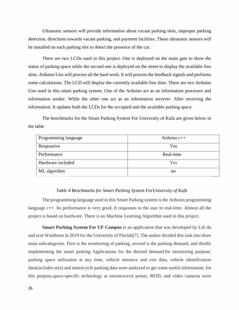
The benchmarks for the Smart Parking System For University of Kufa are given below in
the table
Programming language Arduino c++
Responsive Yes
Performance Real-time
Hardware included Yes
ML algorithm no
Table 4 Benchmarks for Smart Parking System ForUniversity of Kufa
The programming language used in this Smart Parking system is the Arduino programming
language c++. Its performance is very good, It responses to the user in real-time. Almost all the
project is based on hardware. There is no Machine Learning Algorithm used in this project.
Smart Parking System For UF Campus is an application that was developed by Lili du
and scot Washburn in 2019 for the University of Florida[7]. The author divided this task into three
main subcategories. First is the monitoring of parking, second is the parking demand, and thirdly
implementing the smart parking Applications for the desired demand.for monitoring purpose,
parking space utilization at any time, vehicle entrance and exit data, vehicle identification
data(includes size) and motorcycle parking data were analyzed to get some useful information. for
this purpose,space-specific technology at entrance/exit points, RFID, and video cameras were
27
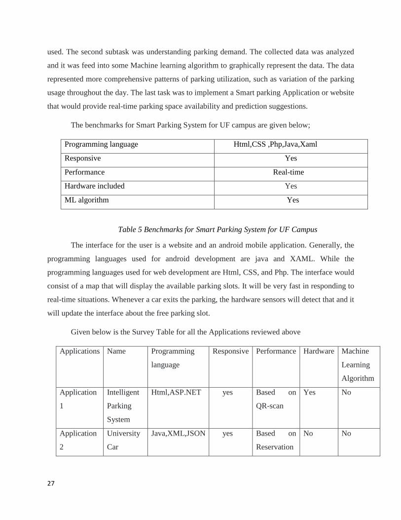
used. The second subtask was understanding parking demand. The collected data was analyzed
and it was feed into some Machine learning algorithm to graphically represent the data. The data
represented more comprehensive patterns of parking utilization, such as variation of the parking
usage throughout the day. The last task was to implement a Smart parking Application or website
that would provide real-time parking space availability and prediction suggestions.
The benchmarks for Smart Parking System for UF campus are given below;
Programming language Html,CSS ,Php,Java,Xaml
Responsive Yes
Performance Real-time
Hardware included Yes
ML algorithm Yes
Table 5 Benchmarks for Smart Parking System for UF Campus
The interface for the user is a website and an android mobile application. Generally, the
programming languages used for android development are java and XAML. While the
programming languages used for web development are Html, CSS, and Php. The interface would
consist of a map that will display the available parking slots. It will be very fast in responding to
real-time situations. Whenever a car exits the parking, the hardware sensors will detect that and it
will update the interface about the free parking slot.
Given below is the Survey Table for all the Applications reviewed above
Applications Name Programming
language
Responsive Performance Hardware Machine
Learning
Algorithm
Application
1
Intelligent
Parking
System
Html,ASP.NET yes Based on
QR-scan
Yes No
Application
2
University
Car
Java,XML,JSON yes Based on
Reservation
No No
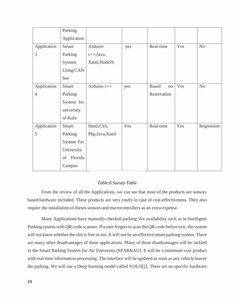
28
Parking
Application
Application
3
Smart
Parking
System
Using CAN
bus
Arduino
c++,Java,
Xaml,NodeJS
yes Real-time Yes No
Application
4
Smart
Parking
System for
university
of Kufa
Arduino c++ yes Based on
Reservation
Yes No
Application
5
Smart
Parking
System For
University
of Florida
Campus
Html,CSS,
Php,Java,Xaml
Yes Real-time Yes Regression
Table 6 Survey Table
From the review of all the Applications, we can see that most of the products are sensors
based hardware included. These products are very costly in case of cost-effectiveness. They also
require the installation of theses sensors and microcontrollers as an extra expense.
Many Applications have manually checked parking slot availability such as in Intelligent
Parking system with QR-code scanner. If a user forgets to scan the QR-code before exit, the system
will not know whether the slot is free or not. It will not be an effective smart parking system. There
are many other disadvantages of these applications. Many of these disadvantages will be tackled
in the Smart Parking System for Air University (SPARKAU). It will be a minimum cost product
with real-time information processing. The interface will be updated as soon as any vehicle leaves
the parking. We will use a Deep learning model called YOLO[2]. There are no specific hardware
29
requirements for SPARKAU because it will utilize the already installed hardware (cameras) in the
parking.
This chapter reviews different types of smart parking applications along with their
benchmarks such as performance, hardware, and machine-learning algorithm included. It
explained the basic working of every application and finally presented a survey table with all the
benchmarks.
*******************************Chapter 2 End******************************
30
Chapter 3
Requirement Specification
There is always the current best existing application of each category. To build a new
product, a new approach has to be followed and a new system is developed. In requirement
specification, all the requirements of the SPARKAU are gathered The same approach is followed
in this chapter. Firstly, the existing best system is explained and the proposed solution is presented
along with its Function and non-functional requirements. Use cases of the proposed solution are
also given in this chapter.
3.1 Existing System (best)
The best Smart Parking System Application based on accuracy, time efficiency, and fuel-
saving is the Smart Parking System for the University of Kufa [8]. Smart Parking System for
the University of Kufa is also a hardware-based system that will use a wireless smart parking
system to tackle the parking problems. Ultrasonic sensors will be used to analyze the situations of
parking.
Ultrasonic sensors will provide information about vacant parking slots, improper parking
detection, directions towards vacant parking, and payment facilities. The ultrasonic sensors would
be embedded in each slot of the parking area to detect the presence of the car. The signals would
be sent from ultrasonic sensors to the Arduino Uno.
There are two Arduino Uno used in this smart parking system. One of the Arduino act as
an information processor and information sender. While the other one act as an information
receiver. The first one which will act as an information sender will receive signals from sensors.
These signals will be processed and sent to the other Arduino Uno. When the other Arduino
receives the information, it updates both the LCDs for the occupied and the available parking space
There are two LCDs used in this project. One is deployed on the main gate to show the
status of parking space while the second one is on the street to display the number of available free
slots.
31
3.1.1 Limitations and drawbacks:
Smart parking systems based on sensors are very accurate and can perform very well.
Many factors are considered when implementing a system for a real-world problem. The priority
is to maximize the utilization of resources. The major drawback of the smart parking system with
hardware is that system is too expensive to implement. Most of the parks, offices, and universities
have a very big area to cover for parking. The overall cost of implementing such systems will go
beyond the expectations. Another major drawback is the malfunctioning of the hardware such as
sensors or boards. It is very time-consuming when it comes to changing the malfunctioning
hardware. Its troubleshooting becomes a very big issue. An inspecting engineer would have to
come to inspect the system. After the troubleshooting of the whole system, the next step would be
the installation of new hardware. Which would also cost extra money to the organization. So it can
be said that the smart parking system with sensors and hardware are not well suited for large
buildings and big organizations. To improve this system, a new proposed system has been
implemented. It has overcome all the drawbacks of the previous system and it is cost & time-
effective.
3.2 Proposed System
Many of the smart parking systems have been implemented using different computer
vision algorithms. Computer vision can also be said as the backbone of the smart parking systems.
The images and videos are the input data for the algorithm, they process the data and provide the
desired output.
SPARKAU (Smart Parking system for Air University) will solve the parking problem very
efficiently. People will be able to park their cars to the vacant parking slot without any difficulty.
SPARKAU will process the videos to calculate the available free slots. Then, it will provide the
interface to look for a parking slot.
SPARKAU will overcome all the issues in the previous system. It will be a time-effective,
cost-efficient, and easy to use the system. It will be completely a software-based System without
any hardware or sensors. The only hardware that would be used in this system is CCTV cameras
that are already deployed by the university admin. The system will process the videos coming from
these cameras. It would only require a simple computer system that could run the software. It
32
would take the input as video from the CCTV cameras already deployed in the parking. It would
then process those images through the algorithm, which will detect the objects in the image. Then
it will get processed from our algorithm which will calculate the occupied space as well as free
space. In the end, the results of the parking area would be uploaded on the website. The website
will get updated every 30 seconds. The system will be very efficient in terms of cost as it would
be free from any type of hardware.
SPARKAU has various minor functions that result in free parking slots. But major
functions of SPARKAU are;
Object detection
Vacant Slot calculation.
Updating the web.
In the first step, the system takes the input from the CCTV camera of the parking. Input is
parameterized with the constraints. YOLO processes the video and it gives the output in the form
of detected objects in the video.
Then in the second step, the video is then fed into our algorithm. It will process it to
calculate the number of cars on the slots and the free space available for more cars. After
calculation, it then outputs the occupied and the available slots.
Finally, that information is passed to our website through API (Application Programming
Interface). API authenticates the request with the API-key; our website calls an API service that
makes a get request to the database. The database then checks for the API key for validation. If
validated, the website is updated and the user can look for the slot to park his car.
3.3 Requirement Specifications
The smart parking system for Air University also known as SPARKAU will consist of a
Web Application or a mobile web application. It will be used by many people from Air
University. Many people use the parking area of our University to park their cars. They just
randomly enter from one side of the parking area hoping to find an empty slot. Most of the times
it happens that they cannot find a vacant slot to park their car. SPARKAU will help them find a
space for car parking.
33
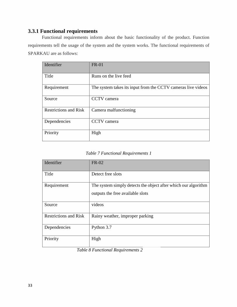
3.3.1 Functional requirements Functional requirements inform about the basic functionality of the product. Function
requirements tell the usage of the system and the system works. The functional requirements of
SPARKAU are as follows:
Identifier FR-01
Title Runs on the live feed
Requirement The system takes its input from the CCTV cameras live videos
Source CCTV camera
Restrictions and Risk Camera malfunctioning
Dependencies CCTV camera
Priority High
Table 7 Functional Requirements 1
Identifier FR-02
Title Detect free slots
Requirement The system simply detects the object after which our algorithm
outputs the free available slots
Source videos
Restrictions and Risk Rainy weather, improper parking
Dependencies Python 3.7
Priority High
Table 8 Functional Requirements 2
34
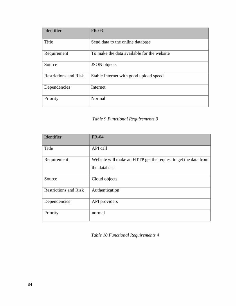
Identifier FR-03
Title Send data to the online database
Requirement To make the data available for the website
Source JSON objects
Restrictions and Risk Stable Internet with good upload speed
Dependencies Internet
Priority Normal
Table 9 Functional Requirements 3
Identifier FR-04
Title API call
Requirement Website will make an HTTP get the request to get the data from
the database
Source Cloud objects
Restrictions and Risk Authentication
Dependencies API providers
Priority normal
Table 10 Functional Requirements 4
35
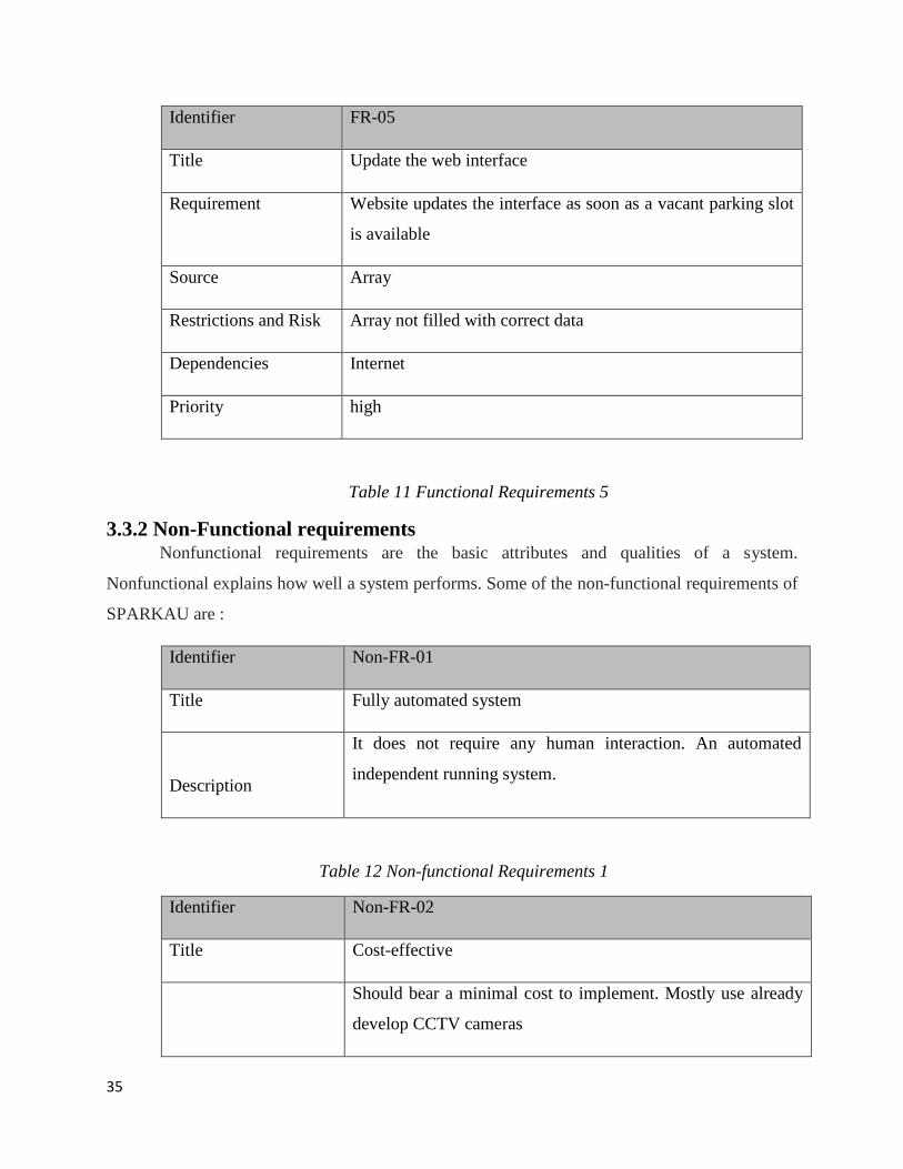
Identifier FR-05
Title Update the web interface
Requirement Website updates the interface as soon as a vacant parking slot
is available
Source Array
Restrictions and Risk Array not filled with correct data
Dependencies Internet
Priority high
Table 11 Functional Requirements 5
3.3.2 Non-Functional requirements
Nonfunctional requirements are the basic attributes and qualities of a system.
Nonfunctional explains how well a system performs. Some of the non-functional requirements of
SPARKAU are :
Identifier Non-FR-01
Title Fully automated system
Description
It does not require any human interaction. An automated
independent running system.
Table 12 Non-functional Requirements 1
Identifier Non-FR-02
Title Cost-effective
Should bear a minimal cost to implement. Mostly use already
develop CCTV cameras
36
Description
Table 13 Non-functional Requirements 2
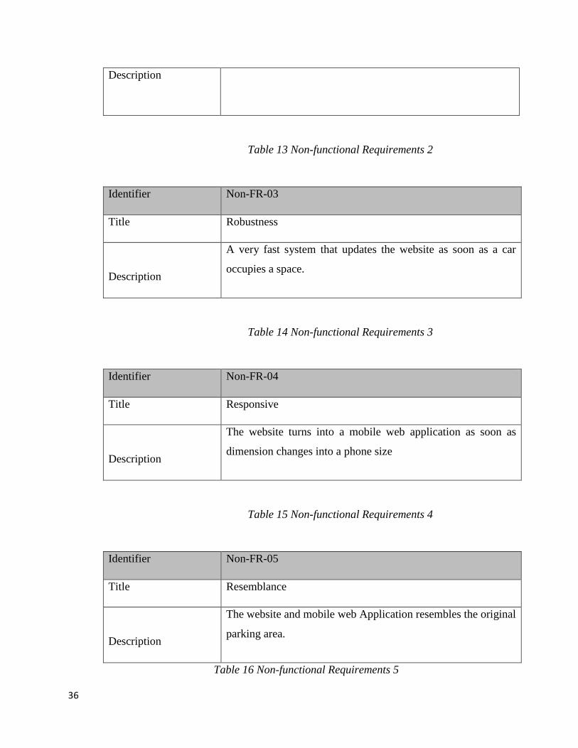
Identifier Non-FR-03
Title Robustness
Description
A very fast system that updates the website as soon as a car
occupies a space.
Table 14 Non-functional Requirements 3
Identifier Non-FR-04
Title Responsive
Description
The website turns into a mobile web application as soon as
dimension changes into a phone size
Table 15 Non-functional Requirements 4
Identifier Non-FR-05
Title Resemblance
Description
The website and mobile web Application resembles the original
parking area.
Table 16 Non-functional Requirements 5
37
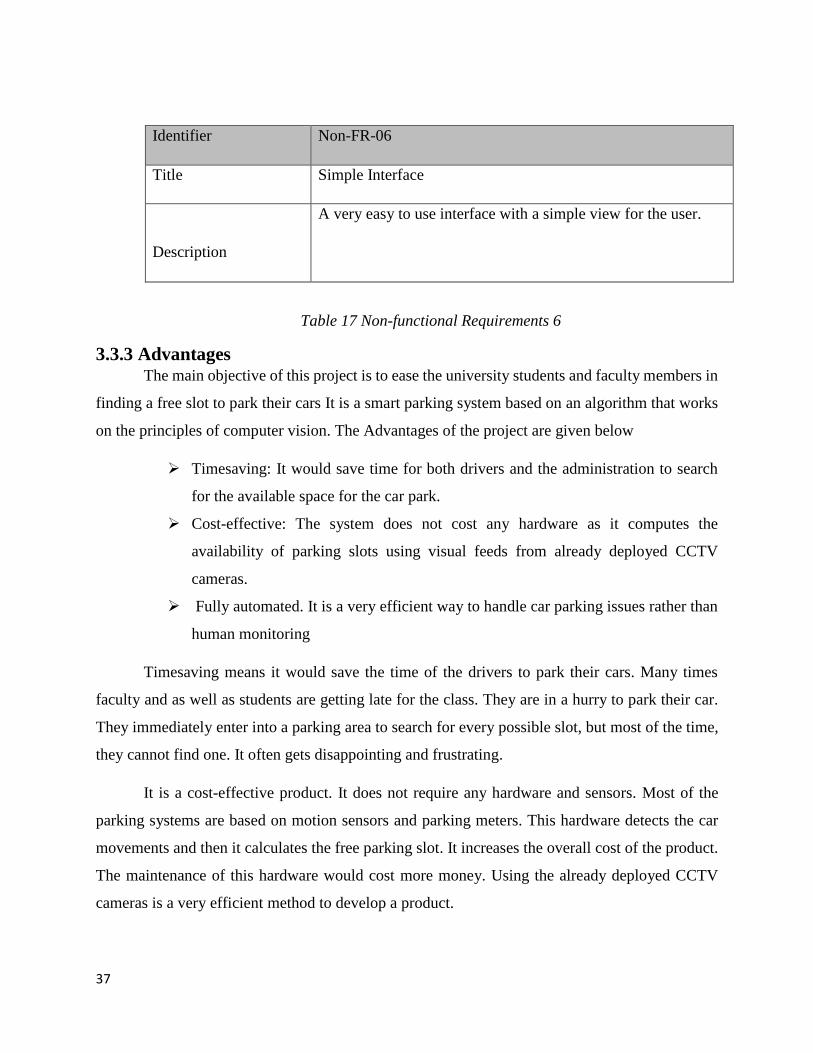
Identifier Non-FR-06
Title Simple Interface
Description
A very easy to use interface with a simple view for the user.
Table 17 Non-functional Requirements 6
3.3.3 Advantages The main objective of this project is to ease the university students and faculty members in
finding a free slot to park their cars It is a smart parking system based on an algorithm that works
on the principles of computer vision. The Advantages of the project are given below
Timesaving: It would save time for both drivers and the administration to search
for the available space for the car park.
Cost-effective: The system does not cost any hardware as it computes the
availability of parking slots using visual feeds from already deployed CCTV
cameras.
Fully automated. It is a very efficient way to handle car parking issues rather than
human monitoring
Timesaving means it would save the time of the drivers to park their cars. Many times
faculty and as well as students are getting late for the class. They are in a hurry to park their car.
They immediately enter into a parking area to search for every possible slot, but most of the time,
they cannot find one. It often gets disappointing and frustrating.
It is a cost-effective product. It does not require any hardware and sensors. Most of the
parking systems are based on motion sensors and parking meters. This hardware detects the car
movements and then it calculates the free parking slot. It increases the overall cost of the product.
The maintenance of this hardware would cost more money. Using the already deployed CCTV
cameras is a very efficient method to develop a product.
38
Fully automated means it should not require human monitoring. In most scenarios in our
university, guards are helping the drivers to find a place to park the cars. This system will be free
from human interaction. The system will update the interface based on live visual feeds, which
will be done as soon as a car leaves the parking. It would decrease the headache of admin as well
as guards to help the drivers find the free parking slot.
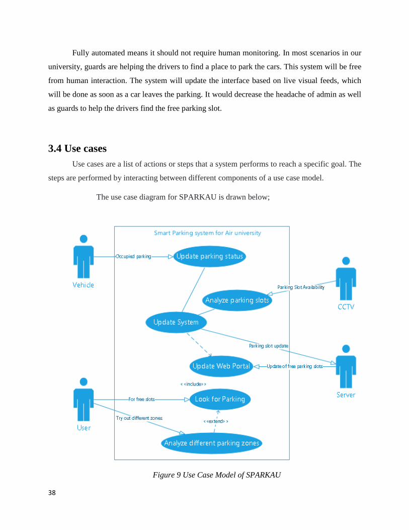
3.4 Use cases
Use cases are a list of actions or steps that a system performs to reach a specific goal. The
steps are performed by interacting between different components of a use case model.
The use case diagram for SPARKAU is drawn below;
Figure 9 Use Case Model of SPARKAU
39
There are four different actors involved in this use case diagram user, vehicle, server, and CCTV.
The vehicle will occupy the parking slot and CCTV will update the system, the server will
continuously look for the new information to update the web portal. The user will analyze the
different parking zones searching for vacant space. The CCTV camera will record the parking zone
and update the system
Use Case ID: UC-01
Use Case Name: Update parking status
Actors: vehicle
Description: Car/vehicle will enter into the parking changing the state of parking status.
Trigger: When the car enters the parking
Preconditions: None
Normal Flow: The car enters the parking area
It will change the parking status from free to occupied
Table 18 Use Case 1
Use Case ID: UC-02
Use Case Name: Analyzing the parking zone
Actors: CCTV
Description: CCTV will be analyzing the car slots in the parking zone and processing the
information about the slots occupied and free slots
40
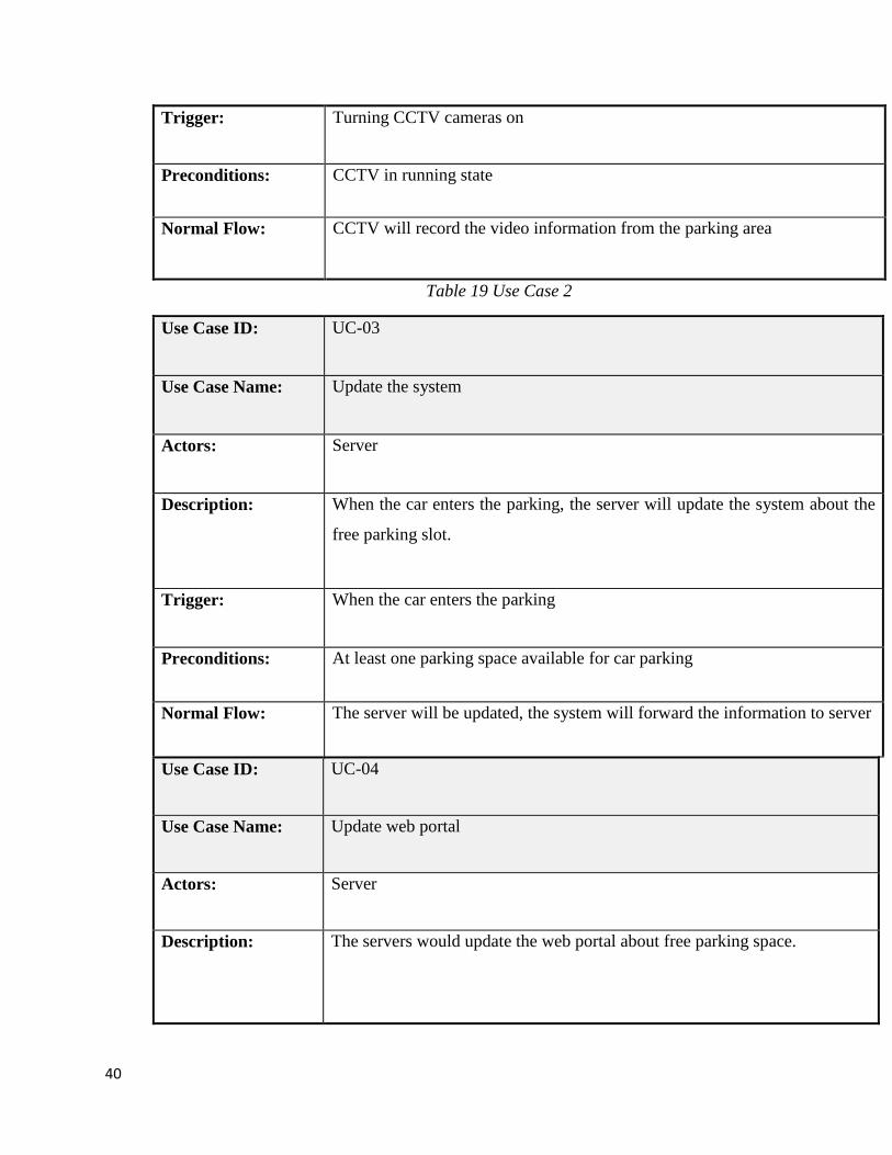
Trigger: Turning CCTV cameras on
Preconditions: CCTV in running state
Normal Flow: CCTV will record the video information from the parking area
Table 19 Use Case 2
Use Case ID: UC-03
Use Case Name: Update the system
Actors: Server
Description: When the car enters the parking, the server will update the system about the
free parking slot.
Trigger: When the car enters the parking
Preconditions: At least one parking space available for car parking
Normal Flow: The server will be updated, the system will forward the information to server
Use Case ID: UC-04
Use Case Name: Update web portal
Actors: Server
Description: The servers would update the web portal about free parking space.
41
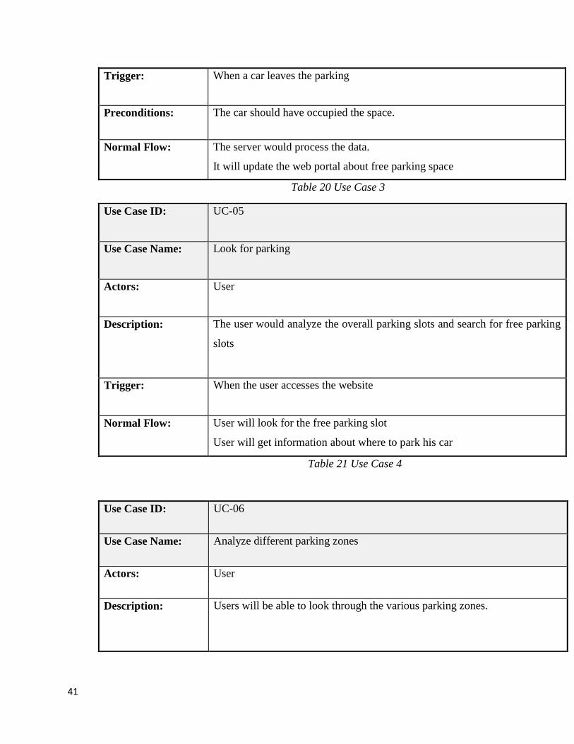
Trigger: When a car leaves the parking
Preconditions: The car should have occupied the space.
Normal Flow: The server would process the data.
It will update the web portal about free parking space
Table 20 Use Case 3
Use Case ID: UC-05
Use Case Name: Look for parking
Actors: User
Description: The user would analyze the overall parking slots and search for free parking
slots
Trigger: When the user accesses the website
Normal Flow: User will look for the free parking slot
User will get information about where to park his car
Table 21 Use Case 4
Use Case ID: UC-06
Use Case Name: Analyze different parking zones
Actors: User
Description: Users will be able to look through the various parking zones.
42
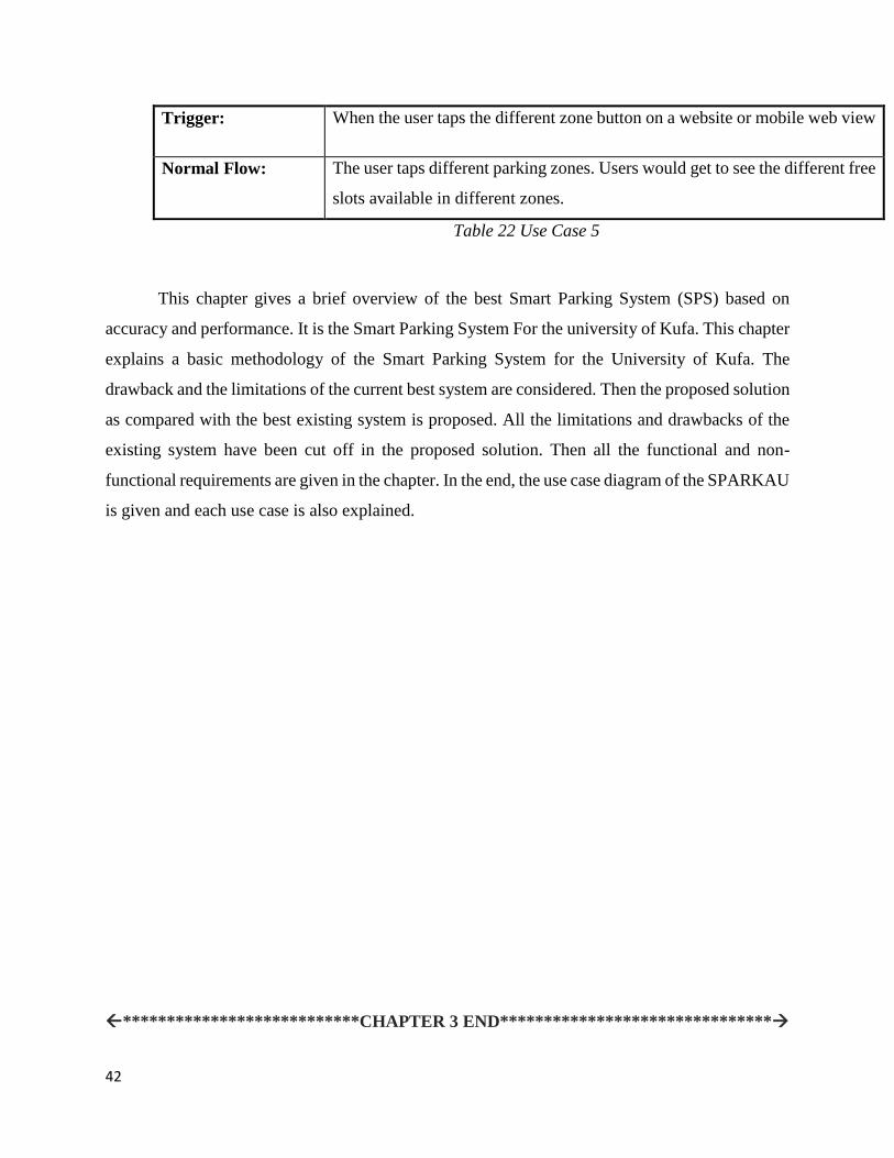
Trigger: When the user taps the different zone button on a website or mobile web view
Normal Flow: The user taps different parking zones. Users would get to see the different free
slots available in different zones.
Table 22 Use Case 5
This chapter gives a brief overview of the best Smart Parking System (SPS) based on
accuracy and performance. It is the Smart Parking System For the university of Kufa. This chapter
explains a basic methodology of the Smart Parking System for the University of Kufa. The
drawback and the limitations of the current best system are considered. Then the proposed solution
as compared with the best existing system is proposed. All the limitations and drawbacks of the
existing system have been cut off in the proposed solution. Then all the functional and non-
functional requirements are given in the chapter. In the end, the use case diagram of the SPARKAU
is given and each use case is also explained.
***************************CHAPTER 3 END*******************************
43
CHAPTER 4
DESIGN
After requirement specifications, the next step is to use these requirements to design the
product. This chapter explains the basic architecture of SPARKAU. It has all the designs,
methodologies, constraints, low-level diagrams, and high-level diagrams. It also explains the
design interface of SPARKAU.
4.1 System Architecture
SPARKAU is a very simple architecture. It has many small components just like any other
software. You give input, the software process that input, and then it displays the result. Input is
transferred to the internal processing from the CCTV cameras. The input will be any form of image
or video. Internal processing will process the information and it will output the data. The website
will display that data in a human-understandable form
The initial phase was to collect the data from the admin of Air University. A legal document
was developed because of security issues. A non-disclosure agreement (NDA) was signed
between both parties. The higher authorities of the Computer Science Department also signed this
NDA. Then Data was acquired from the security office.
The next step was to select a suitable model for our specific situation of computer vision.
The situation is critical in such a way that the cars are parked sidewise and the camera’s view is
tilted. To get the object detection correctly, the algorithm has to be chosen very carefully with
testing. We tested several algorithms such as support vector machine (SVM), single-shot detector
(SSD), regional convolutional neural network(R-CNN) and, Mask-RCNN, and YOLO. The
difference between mask-RCNN and RCNN is that mask-RCNN overlays a mask on the object
being detected and it is more accurate.
After the selection of the Algorithm was completed, the next phase was to tune the
parameters. The algorithm was run on several images from the parking videos and was tested on
different threshold and confidence. After a series of experiments, threshold and confidence were
decided. Then the original data were tested to analyze the working of the algorithm. After that
44
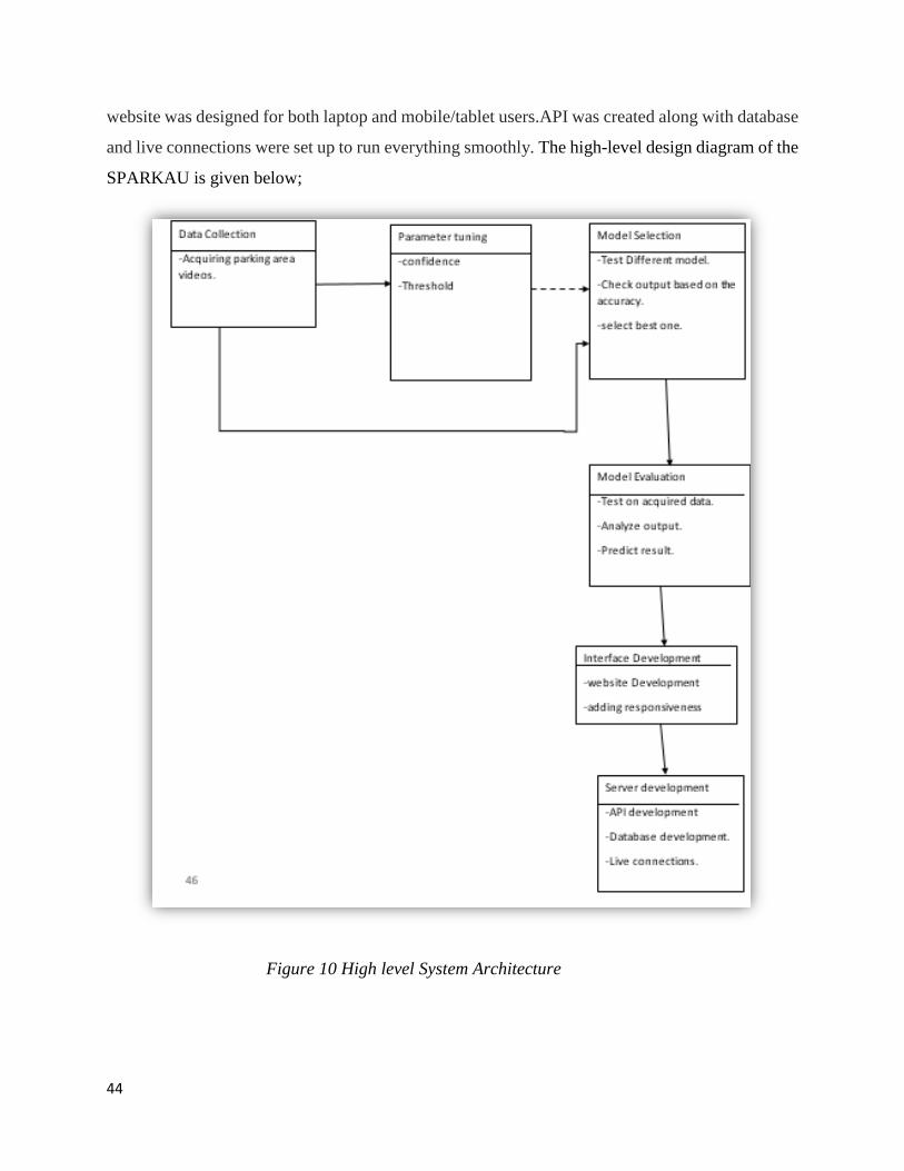
website was designed for both laptop and mobile/tablet users.API was created along with database
and live connections were set up to run everything smoothly. The high-level design diagram of the
SPARKAU is given below;
Figure 10 High level System Architecture
45
4.2 Design Constrains
Constraints are the limitations of the project. In the design phase, several constraints were
faced when the system was designed. The major constrains of the SPARKAU were
Detection Constraints
Training Constrain
Annotation Constrains
Data Collection
Detection Constrain was the limitation of the YOLO algorithm. When YOLO was run, it
only detected those objects whose bounding boxes could be drawn. It does not detect those objects,
which are a little bit hidden behind the car. As the parking area of our university is tilted. The
cameras are also harnessed sidewise. Detecting the cars behind cars is a major constrain of this
project.
Training Constrain was also a hurdle in the design phase because of the two things, first
because of short of resources for training the data model, secondly, the data collection constraints
which will be explained later. for training a YOLO model, it was required to have almost 1000
images/video datasets which is a big constrain.
Annotation Constrain means we had to annotate those training datasets, which is
dependent on data collection. for any classification algorithm to work, we have to feed it different
images with annotations on it about the class. The algorithm will start training and will try to
recognize the features of the image from the annotation as its class.
Data Collection is the basic step of any project. For this purpose, we visited the admin of
Air University several times but due to security reasons, they did not allow us to collect the data.
We visited them several times submitting applications to allow us to collect the data. In the end,
we managed to get some of the chunks of videos because of Non-Disclosure Agreement was
signed. These videos were not enough to train the model or annotate the data for the testing or
classification phase.
46
4.3 Design Methodology
The methodology is the systematic set of methods applied to a particular system to get a
resultant product. These sets of methods define what would be the outcome of the effort. The
design methodology is the set of methods followed to get a working design. The Design
methodology diagram explains how the methods have been implemented.
Many people consider the waterfall method to be the most traditional software
development method. The waterfall method is a rigid linear model that consists of sequential
phases (requirements, design, implementation, verification, maintenance) focusing on distinct
goals. Each phase must be 100% complete before the next phase can start. There’s usually no
process for going back to modify the project or direction
SPARKAU has been developed according to the waterfall methodology. The steps
included are the Requirement gathering phase, Designing phase, Implementation phase, Testing,
and verification phase, and the last phase is the maintenance phase. In the requirement specification
phase, all the requirements of the SPARKAU were specified. Many research papers were gathered
related to the smart parking system. Other various papers include different types of machine
learning algorithms research papers. After that, a list of requirements was written. This list
specifically includes the input that the system will accept and the output which it will produce after
processing. The next step was to design the SPARKAU architecture along with the subparts and
modules. In the design phase, requirement specifications were studied and a bunch of ideas was
given for the design. The architecture of SPARKAU was designed.
The next phase is implementation. In the implementation phase, small chunks of code were
developed and these units were tested individually. Then in the next phase, these chunk of code
were integrated and a full fledge software unit was developed. The software was tested to be free
from any errors. Then the system was maintained to keep the code running and free from any type
of errors.
47
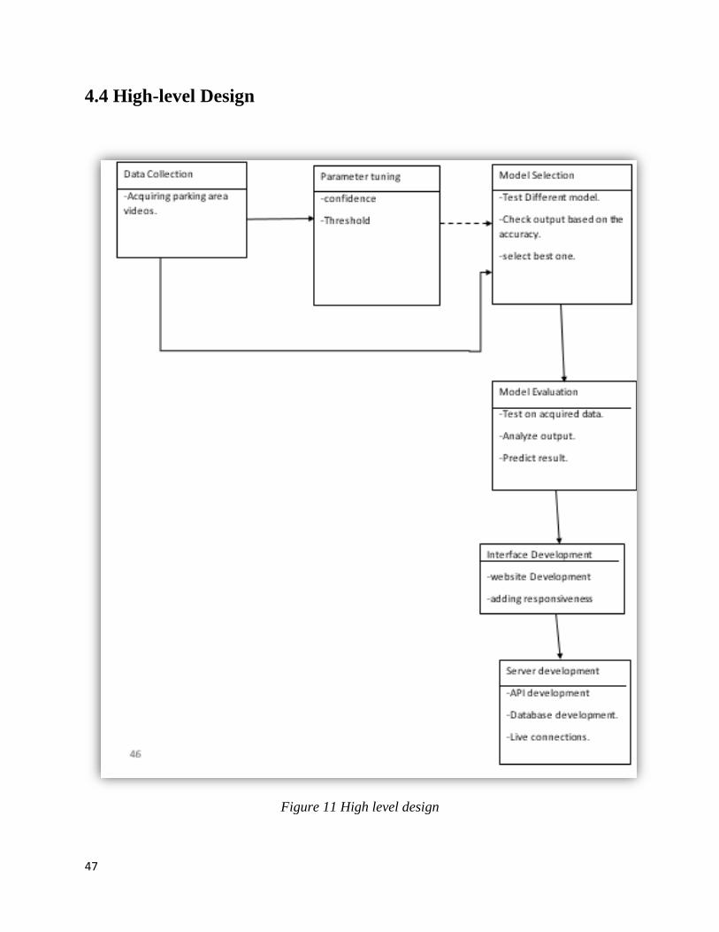
4.4 High-level Design
Figure 11 High level design
48
The high-level design architecture of SPARKAU is given above. It has all the modules that are
necessary to build a smart parking system. In the first module, it has a data acquiring step in which
the data is gathered. Data gathering is the basic starting point for any product to be accurate. Due
to security reasons, Air university did not allow anyone to access the parking videos without
permission from AD security. After many application submissions, They decided to give us the
videos but they restrict us to write a non-disclosure agreement. It was signed by Departments head
and security office’s focal person.
The subsequent step was the model selection. In the model selection phase, we first studied
the best computer vision algorithms around the globe. We run those models on some specific data
sets. The output of each algorithm was stored for comparison. Several algorithms were tested and
compared based on speed and accuracy. Finally, one of the algorithms called YOLO[2]
outperformed every other one.
The parameters of the algorithm were tuned based on accuracy. Two parameters of YOLO
needs to be tuned, Confidence, and threshold. Confidence is the percentage of the object belonging
to a class e.g. YOLO tells that a car in an image has 70% confidence that means YOLO is 70%
sure that the object belongs to car class. While threshold means YOLO tells how sure it is for that
part of the image is an object. After the parameter tuning, the model was evaluated. It was run on
the dataset of the university parking area. The output of the algorithm was collected and the results
were predicted. YOLO performed with much accuracy on our data.
The next phase started designing the interface. The interface is compatible with android
users, ios users, tablet users, and pc users. It is a responsive website that responds based on screen
size. After developing the website, the next step was hosting the website. For students, many
people prefer going for minimum resource use, so we uploaded the website on “000webhost”,
which provides free hosting and domain for one year. API and database were created for live
connections between the website and the backend code. the database and API were created to send
the output from the YOLO code to the website.
49
4.5 Low-level Design
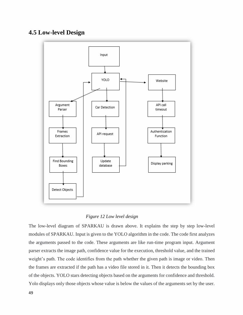
Figure 12 Low level design
The low-level diagram of SPARKAU is drawn above. It explains the step by step low-level
modules of SPARKAU. Input is given to the YOLO algorithm in the code. The code first analyzes
the arguments passed to the code. These arguments are like run-time program input. Argument
parser extracts the image path, confidence value for the execution, threshold value, and the trained
weight’s path. The code identifies from the path whether the given path is image or video. Then
the frames are extracted if the path has a video file stored in it. Then it detects the bounding box
of the objects. YOLO stars detecting objects based on the arguments for confidence and threshold.
Yolo displays only those objects whose value is below the values of the arguments set by the user.
50
Our algorithm running alongside YOLO gets those output and performs some processing. It
detects the free slots in the input and makes an API request. The data is updated in the database.
While on the other hand, the website continuously makes an API call after every 30 seconds out.
The database authenticates the API call with API-key. If authenticated, the database allows API to
access the data, and the website is updated.
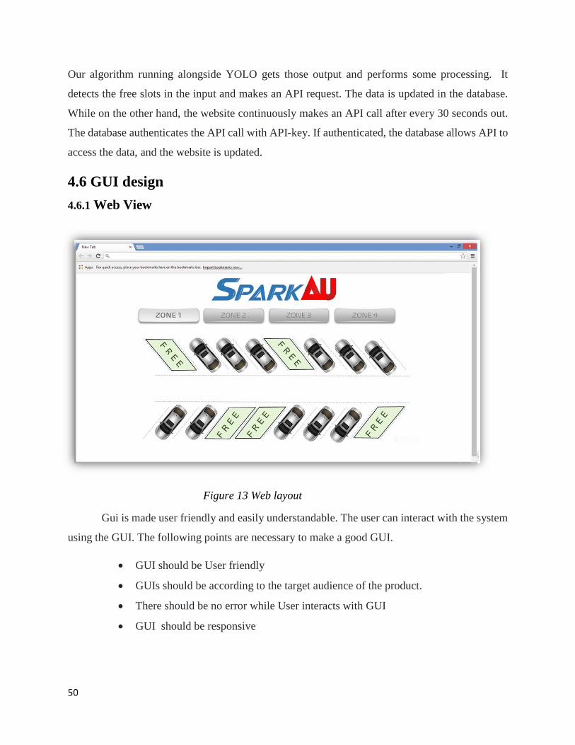
4.6 GUI design
4.6.1 Web View
Figure 13 Web layout
Gui is made user friendly and easily understandable. The user can interact with the system
using the GUI. The following points are necessary to make a good GUI.
GUI should be User friendly
GUIs should be according to the target audience of the product.
There should be no error while User interacts with GUI
GUI should be responsive
51
The front-end website design of SPARKAU is shown above. The topmost part is the logo of our
project. It will be a simple image. These buttons will display different parking zones. Each zone
will consist of different parking slots. These zones represent the different CCTV cameras in the
parking area. Each zone consists of different slots representing the vacant or engaged parking slots
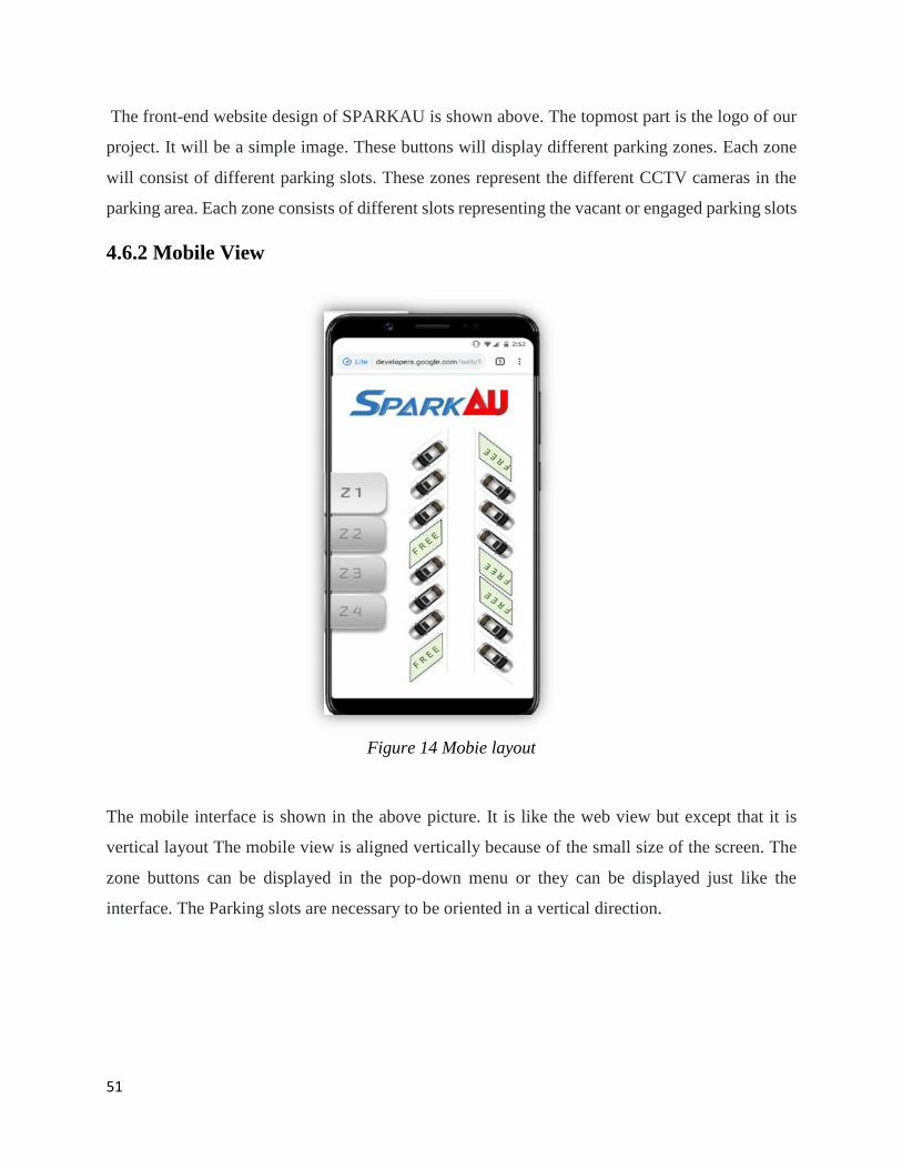
4.6.2 Mobile View
Figure 14 Mobie layout
The mobile interface is shown in the above picture. It is like the web view but except that it is
vertical layout The mobile view is aligned vertically because of the small size of the screen. The
zone buttons can be displayed in the pop-down menu or they can be displayed just like the
interface. The Parking slots are necessary to be oriented in a vertical direction.
52
This chapter concludes all the design phases of SPARKAU. All the previous requirement
specifications are used in the design phase.it has the basic system architecture of SPARKAU. All
the design methodology diagrams and interfaces are a part of this chapter. High-level diagram,
low-level diagram, design constraints, design methodology, system architecture, and GUI have
been explained with details.
************************Chapter 4 End**************************
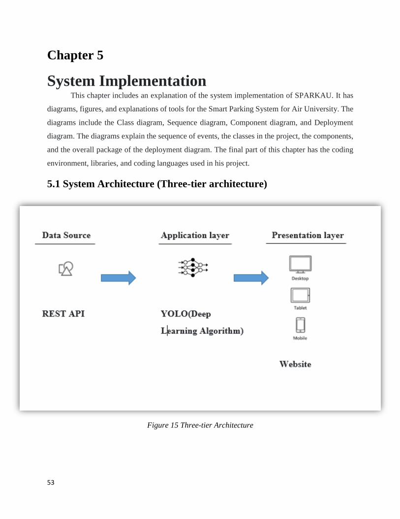
53
Chapter 5
System Implementation This chapter includes an explanation of the system implementation of SPARKAU. It has
diagrams, figures, and explanations of tools for the Smart Parking System for Air University. The
diagrams include the Class diagram, Sequence diagram, Component diagram, and Deployment
diagram. The diagrams explain the sequence of events, the classes in the project, the components,
and the overall package of the deployment diagram. The final part of this chapter has the coding
environment, libraries, and coding languages used in his project.
5.1 System Architecture (Three-tier architecture)
Figure 15 Three-tier Architecture
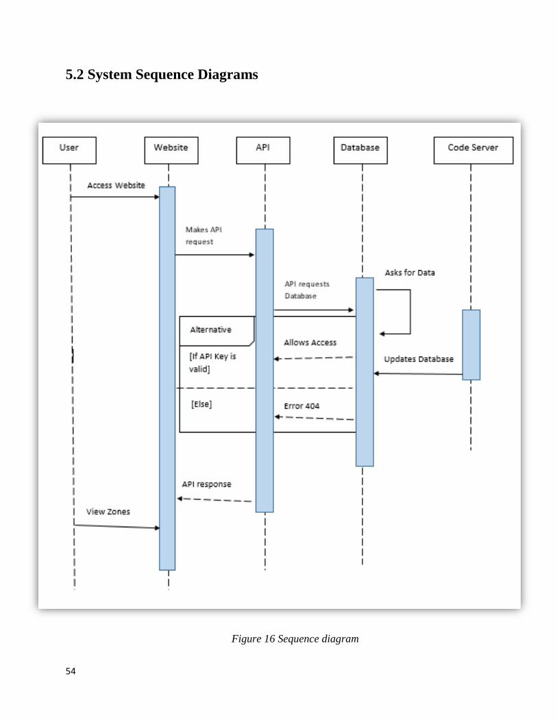
54
5.2 System Sequence Diagrams
Figure 16 Sequence diagram
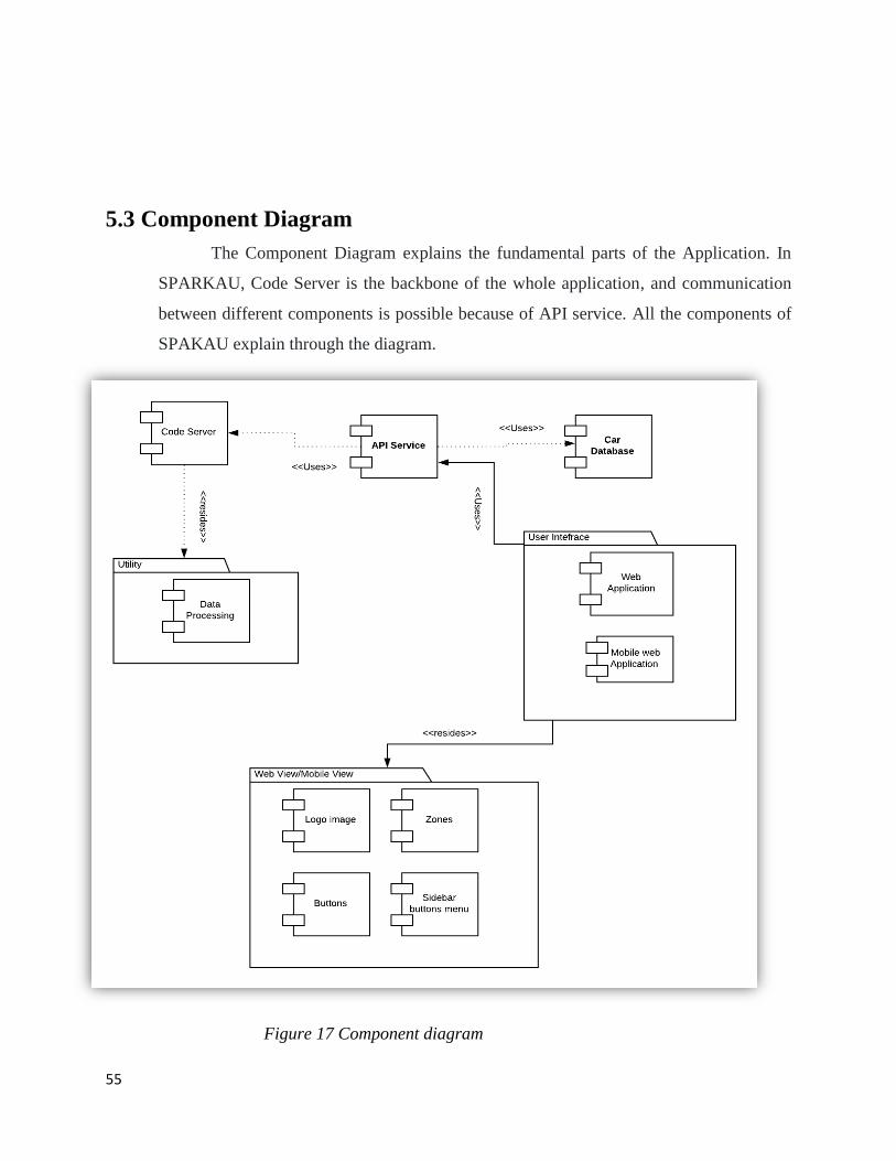
55
5.3 Component Diagram
The Component Diagram explains the fundamental parts of the Application. In
SPARKAU, Code Server is the backbone of the whole application, and communication
between different components is possible because of API service. All the components of
SPAKAU explain through the diagram.
Figure 17 Component diagram
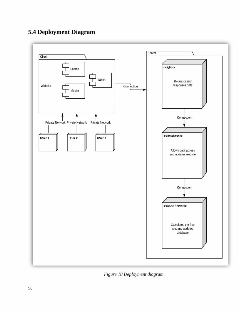
56
5.4 Deployment Diagram
Figure 18 Deployment diagram
57
5.5 Tools and Technologies
1. Programming language The programming languages used in this project are python, angular, and bootstrap. The
frontend side is developed in angular and bootstrap while all the backend algorithm process is in
python
2. Programming APIs The API used for data transfer between different components of the product is a
RESTFULL API. it will travel the data from the database to the hosted website of SPARKAU.
3.Programming Libraries OpenCV,NumPy,Imutils,ArgParse
4.Programming Environment The environment for the project is python 3 with anaconda, while code is written in
pycharm, while the front end is developed in the CLI environment for the angular and coding
environment is NodejS with visual studio code as a code editor.
These diagrams explain the basic structure of the product and the events occurring in this product.
SPARKAU has been developed using three-tier architecture. The component diagram explains the
components of the product. The deployment diagram has overall components that are packaged to
make a big unit. The class diagram explains the relation of classes among each other and their
functions. .It explains the over-all components and packages of the SPARKAU. This chapter also
has an explanation of languages and the environment used for development.
************************Chapter 5 End***********************
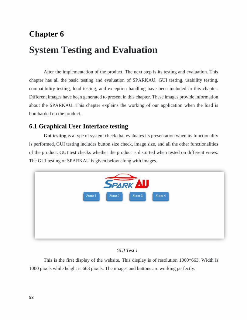
58
Chapter 6
System Testing and Evaluation
After the implementation of the product. The next step is its testing and evaluation. This
chapter has all the basic testing and evaluation of SPARKAU. GUI testing, usability testing,
compatibility testing, load testing, and exception handling have been included in this chapter.
Different images have been generated to present in this chapter. These images provide information
about the SPARKAU. This chapter explains the working of our application when the load is
bombarded on the product.
6.1 Graphical User Interface testing
Gui testing is a type of system check that evaluates its presentation when its functionality
is performed. GUI testing includes button size check, image size, and all the other functionalities
of the product. GUI test checks whether the product is distorted when tested on different views.
The GUI testing of SPARKAU is given below along with images.
GUI Test 1
This is the first display of the website. This display is of resolution 1000*663. Width is
1000 pixels while height is 663 pixels. The images and buttons are working perfectly.
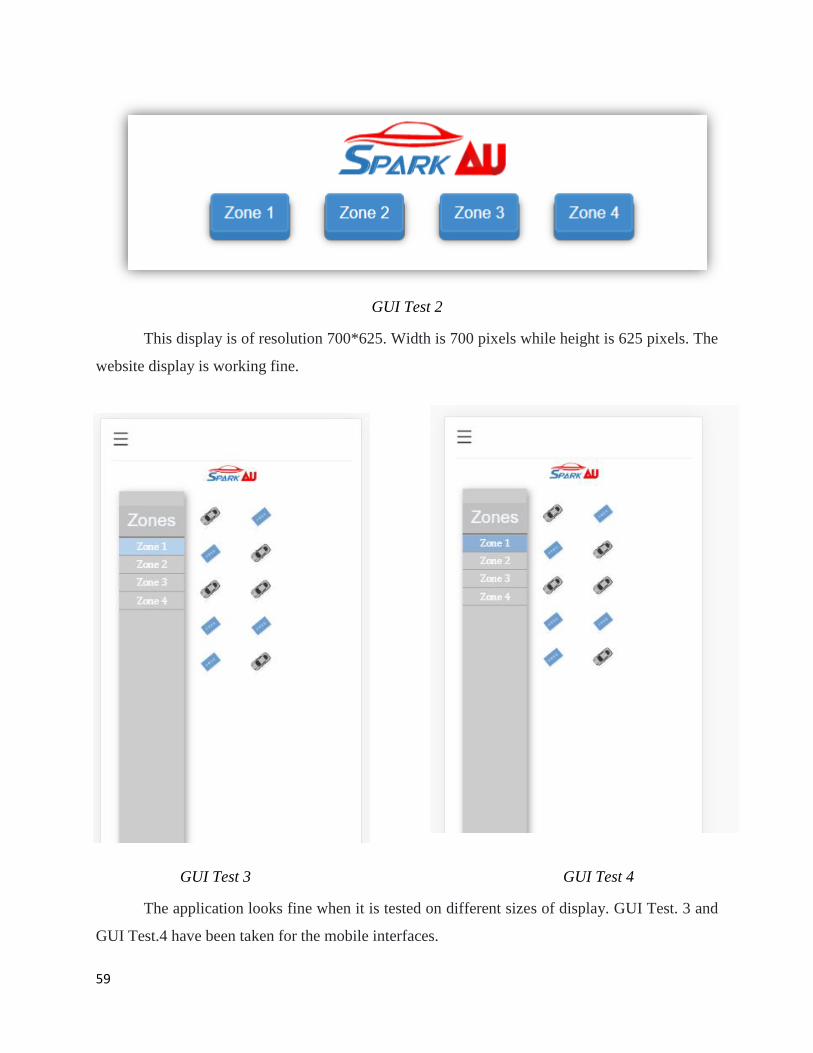
59
GUI Test 2
This display is of resolution 700*625. Width is 700 pixels while height is 625 pixels. The
website display is working fine.
GUI Test 3 GUI Test 4
The application looks fine when it is tested on different sizes of display. GUI Test. 3 and
GUI Test.4 have been taken for the mobile interfaces.
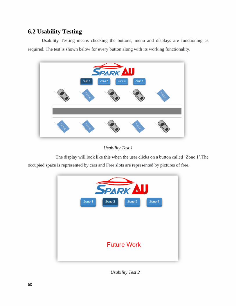
60
6.2 Usability Testing
Usability Testing means checking the buttons, menu and displays are functioning as
required. The test is shown below for every button along with its working functionality.
Usability Test 1
The display will look like this when the user clicks on a button called ‘Zone 1’.The
occupied space is represented by cars and Free slots are represented by pictures of free.
Usability Test 2
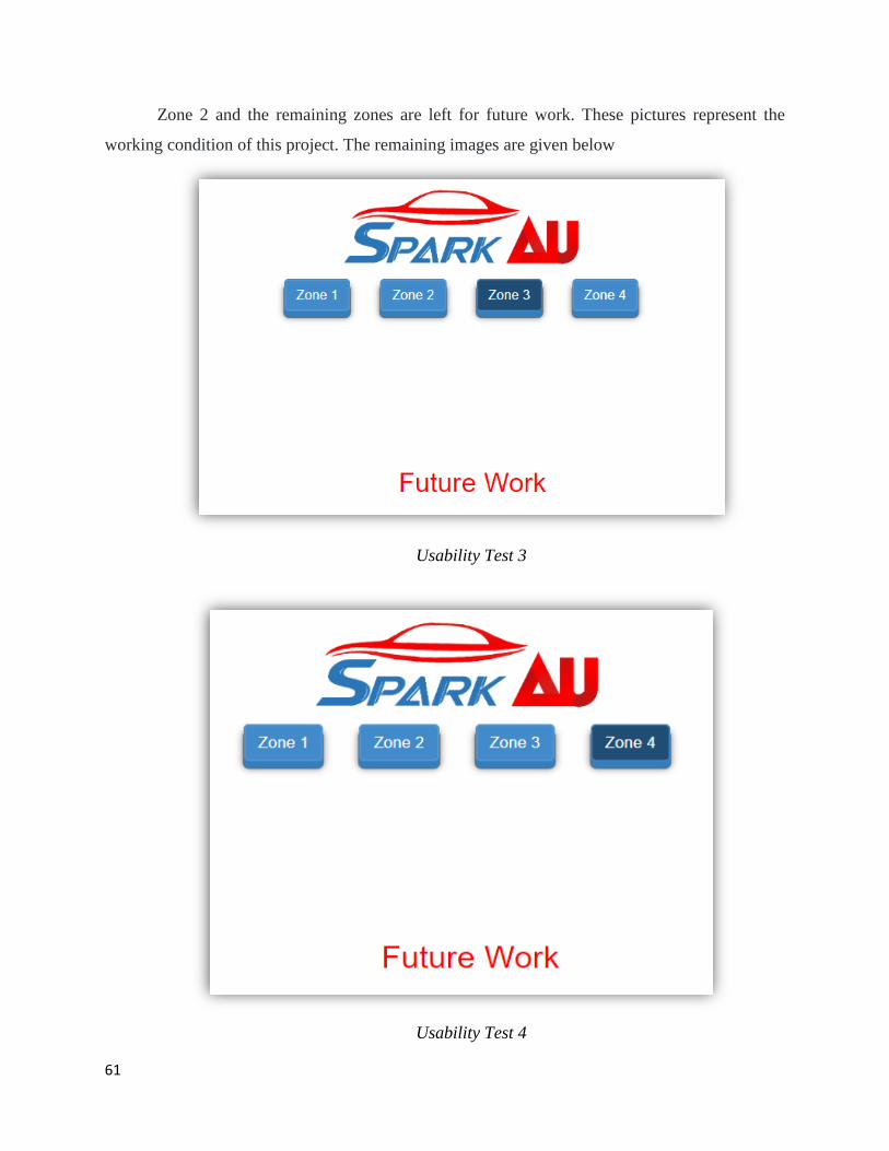
61
Zone 2 and the remaining zones are left for future work. These pictures represent the
working condition of this project. The remaining images are given below
Usability Test 3
Usability Test 4
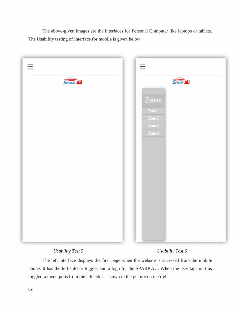
62
The above-given images are the interfaces for Personal Computer like laptops or tablets.
The Usability testing of Interface for mobile is given below
Usability Test 5 Usability Test 6
The left interface displays the first page when the website is accessed from the mobile
phone. It has the left sidebar toggler and a logo for the SPARKAU. When the user taps on this
toggler, a menu pops from the left side as shown in the picture on the right
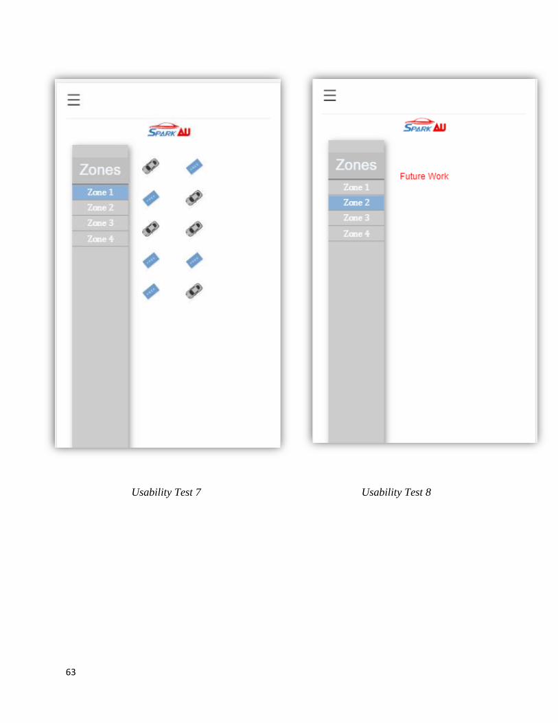
63
Usability Test 7 Usability Test 8
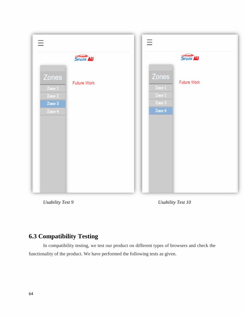
64
Usability Test 9 Usability Test 10
6.3 Compatibility Testing
In compatibility testing, we test our product on different types of browsers and check the
functionality of the product. We have performed the following tests as given.
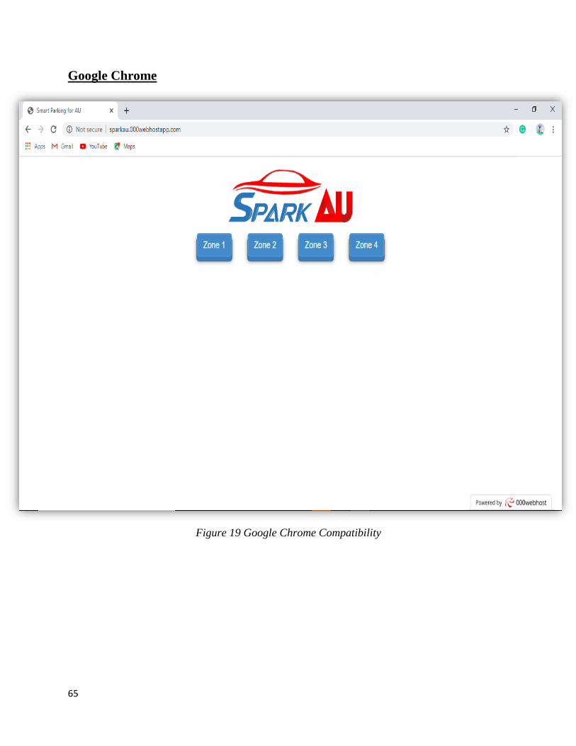
65
Google Chrome
Figure 19 Google Chrome Compatibility
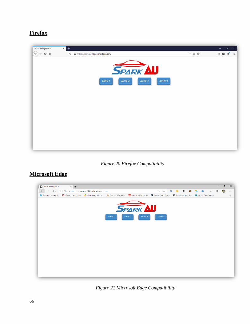
66
Firefox
Figure 20 Firefox Compatibility
Microsoft Edge
Figure 21 Microsoft Edge Compatibility
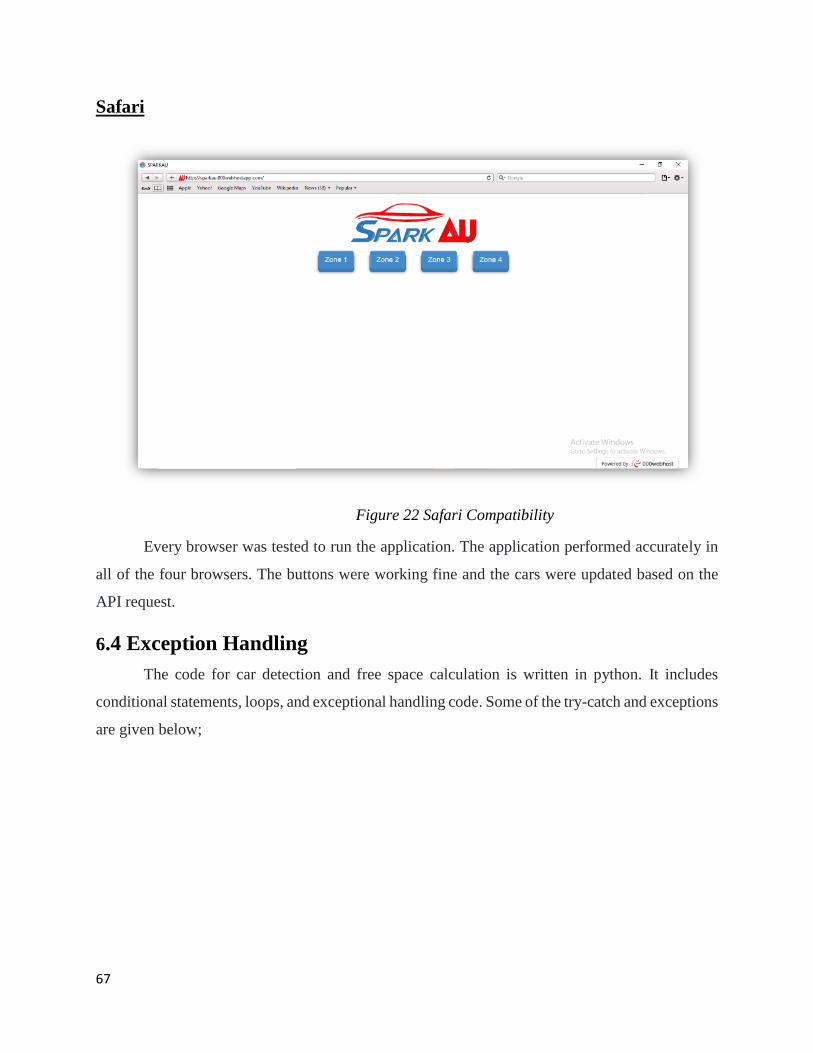
67
Safari
Figure 22 Safari Compatibility
Every browser was tested to run the application. The application performed accurately in
all of the four browsers. The buttons were working fine and the cars were updated based on the
API request.
6.4 Exception Handling
The code for car detection and free space calculation is written in python. It includes
conditional statements, loops, and exceptional handling code. Some of the try-catch and exceptions
are given below;
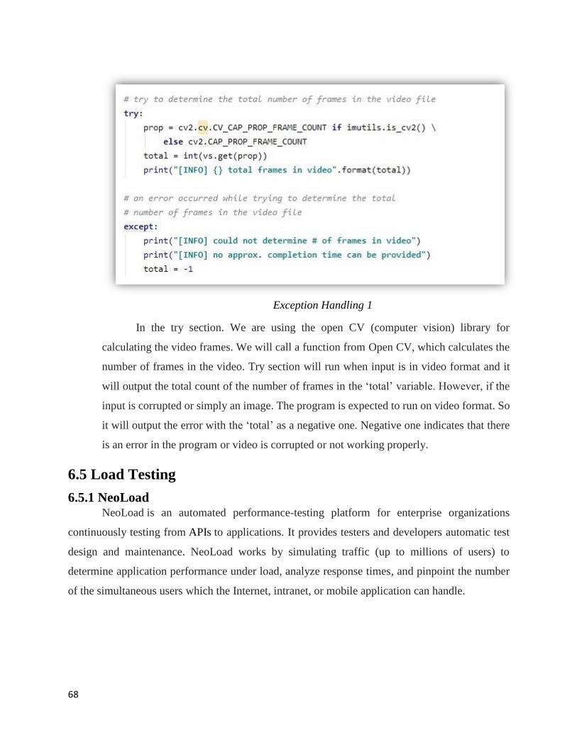
68
Exception Handling 1
In the try section. We are using the open CV (computer vision) library for
calculating the video frames. We will call a function from Open CV, which calculates the
number of frames in the video. Try section will run when input is in video format and it
will output the total count of the number of frames in the ‘total’ variable. However, if the
input is corrupted or simply an image. The program is expected to run on video format. So
it will output the error with the ‘total’ as a negative one. Negative one indicates that there
is an error in the program or video is corrupted or not working properly.
6.5 Load Testing
6.5.1 NeoLoad NeoLoad is an automated performance-testing platform for enterprise organizations
continuously testing from APIs to applications. It provides testers and developers automatic test
design and maintenance. NeoLoad works by simulating traffic (up to millions of users) to
determine application performance under load, analyze response times, and pinpoint the number
of the simultaneous users which the Internet, intranet, or mobile application can handle.
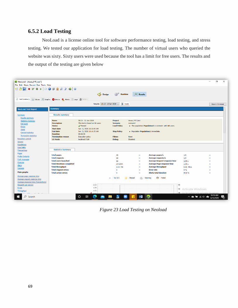
69
6.5.2 Load Testing
NeoLoad is a license online tool for software performance testing, load testing, and stress
testing. We tested our application for load testing. The number of virtual users who queried the
website was sixty. Sixty users were used because the tool has a limit for free users. The results and
the output of the testing are given below
Figure 23 Load Testing on Neoload
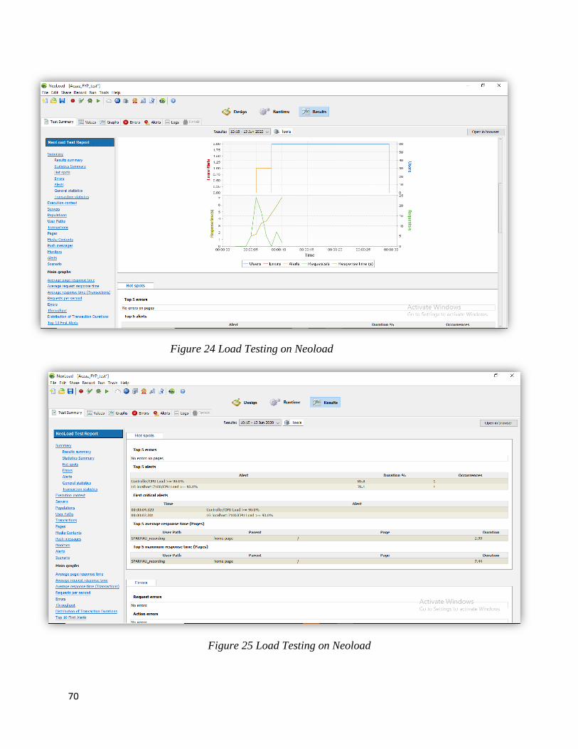
70
Figure 24 Load Testing on Neoload
Figure 25 Load Testing on Neoload
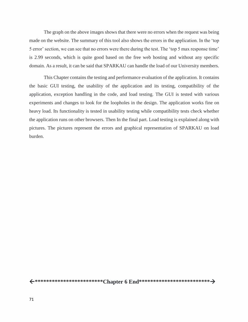
71
The graph on the above images shows that there were no errors when the request was being
made on the website. The summary of this tool also shows the errors in the application. In the ‘top
5 error’ section, we can see that no errors were there during the test. The ‘top 5 max response time’
is 2.99 seconds, which is quite good based on the free web hosting and without any specific
domain. As a result, it can be said that SPARKAU can handle the load of our University members.
This Chapter contains the testing and performance evaluation of the application. It contains
the basic GUI testing, the usability of the application and its testing, compatibility of the
application, exception handling in the code, and load testing. The GUI is tested with various
experiments and changes to look for the loopholes in the design. The application works fine on
heavy load. Its functionality is tested in usability testing while compatibility tests check whether
the application runs on other browsers. Then In the final part. Load testing is explained along with
pictures. The pictures represent the errors and graphical representation of SPARKAU on load
burden.
************************Chapter 6 End*************************
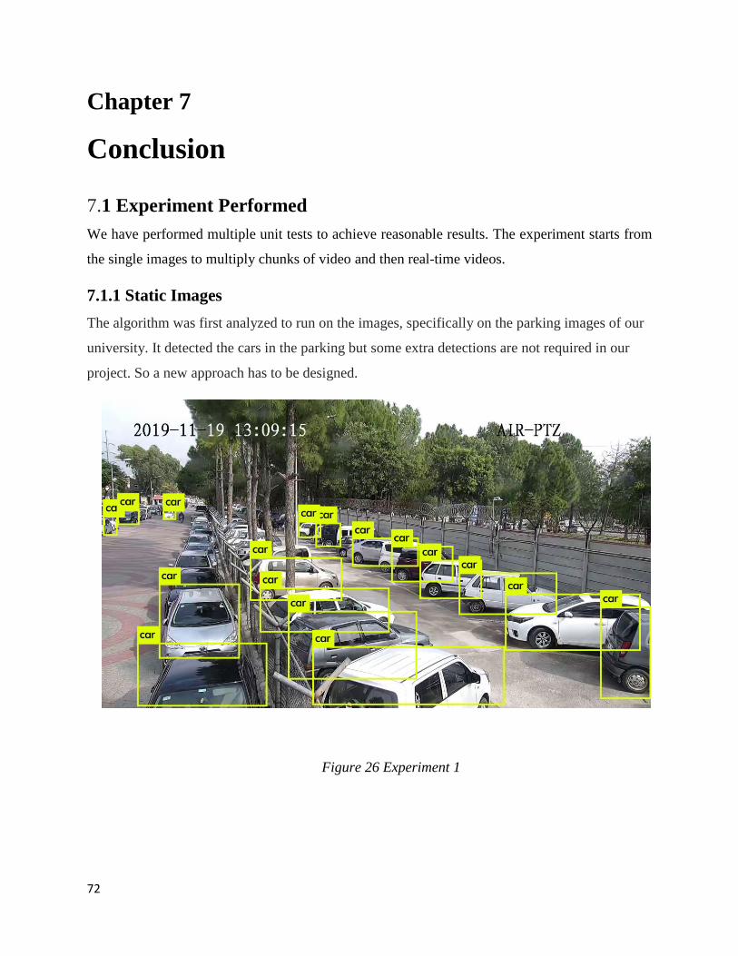
72
Chapter 7
Conclusion
7.1 Experiment Performed
We have performed multiple unit tests to achieve reasonable results. The experiment starts from
the single images to multiply chunks of video and then real-time videos.
7.1.1 Static Images
The algorithm was first analyzed to run on the images, specifically on the parking images of our
university. It detected the cars in the parking but some extra detections are not required in our
project. So a new approach has to be designed.
Figure 26 Experiment 1
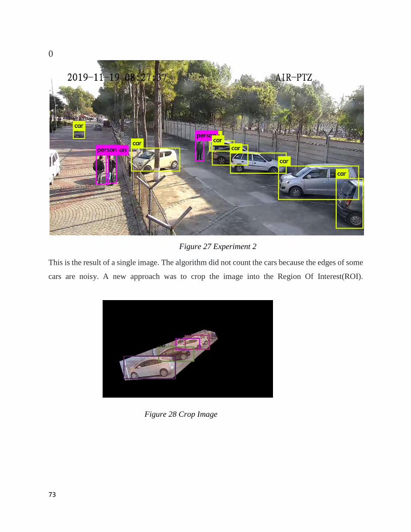
73
0
Figure 27 Experiment 2
This is the result of a single image. The algorithm did not count the cars because the edges of some
cars are noisy. A new approach was to crop the image into the Region Of Interest(ROI).
Figure 28 Crop Image
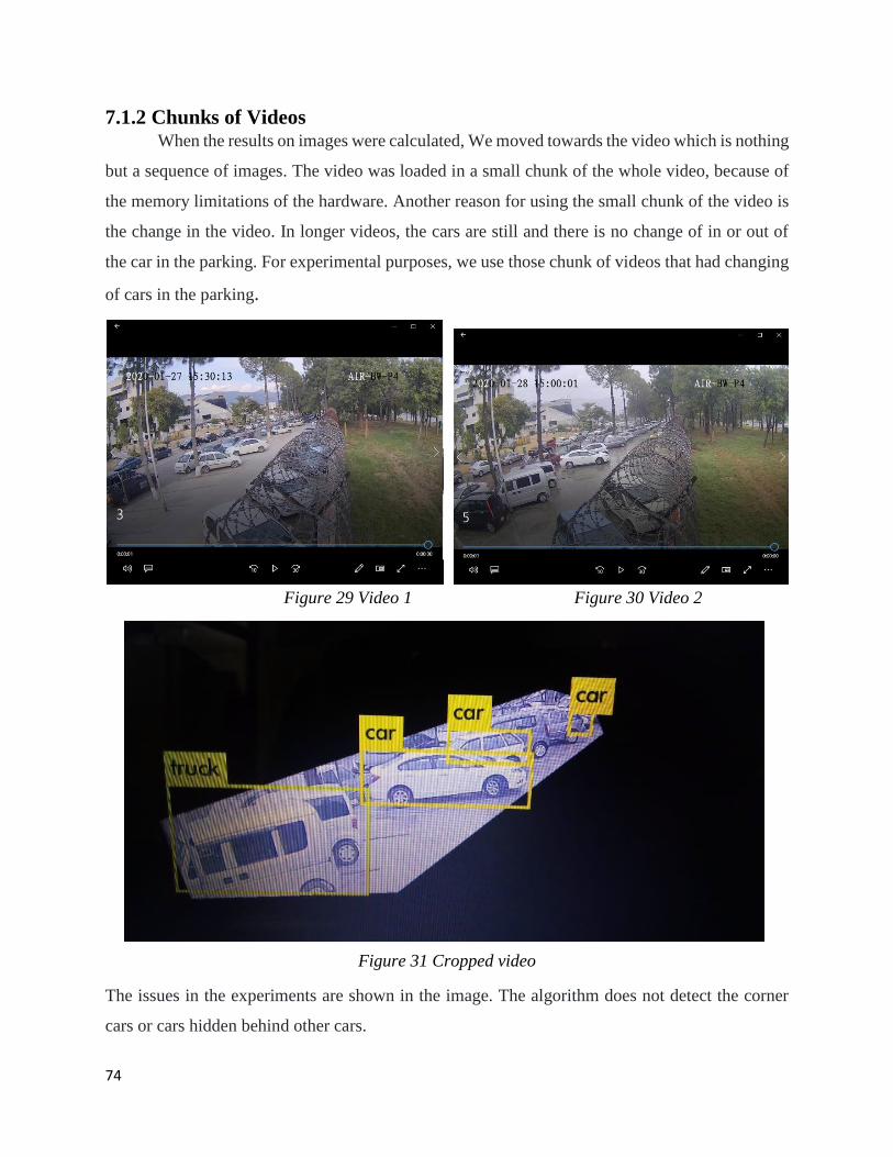
74
7.1.2 Chunks of Videos When the results on images were calculated, We moved towards the video which is nothing
but a sequence of images. The video was loaded in a small chunk of the whole video, because of
the memory limitations of the hardware. Another reason for using the small chunk of the video is
the change in the video. In longer videos, the cars are still and there is no change of in or out of
the car in the parking. For experimental purposes, we use those chunk of videos that had changing
of cars in the parking.
Figure 29 Video 1 Figure 30 Video 2
Figure 31 Cropped video
The issues in the experiments are shown in the image. The algorithm does not detect the corner
cars or cars hidden behind other cars.
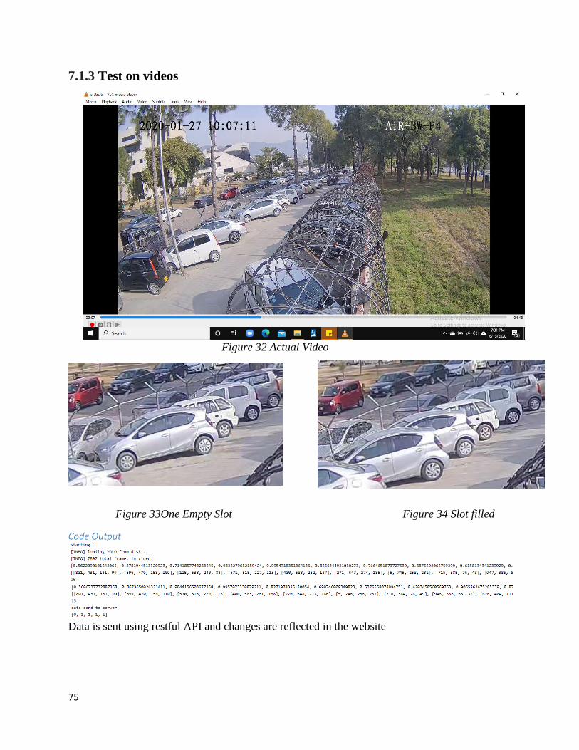
75
7.1.3 Test on videos
Figure 32 Actual Video
Figure 33One Empty Slot Figure 34 Slot filled
Code Output
Data is sent using restful API and changes are reflected in the website
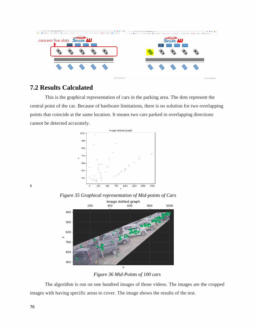
76
7.2 Results Calculated
This is the graphical representation of cars in the parking area. The dots represent the
central point of the car. Because of hardware limitations, there is no solution for two overlapping
points that coincide at the same location. It means two cars parked in overlapping directions
cannot be detected accurately.
s
Figure 35 Graphical representation of Mid-points of Cars
Figure 36 Mid-Points of 100 cars
The algorithm is run on one hundred images of those videos. The images are the cropped
images with having specific areas to cover. The image shows the results of the test.
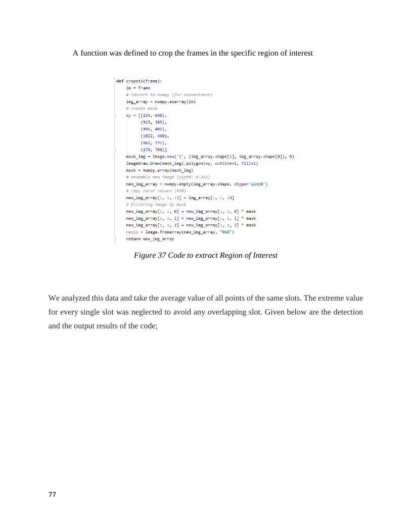
77
A function was defined to crop the frames in the specific region of interest
Figure 37 Code to extract Region of Interest
We analyzed this data and take the average value of all points of the same slots. The extreme value
for every single slot was neglected to avoid any overlapping slot. Given below are the detection
and the output results of the code;
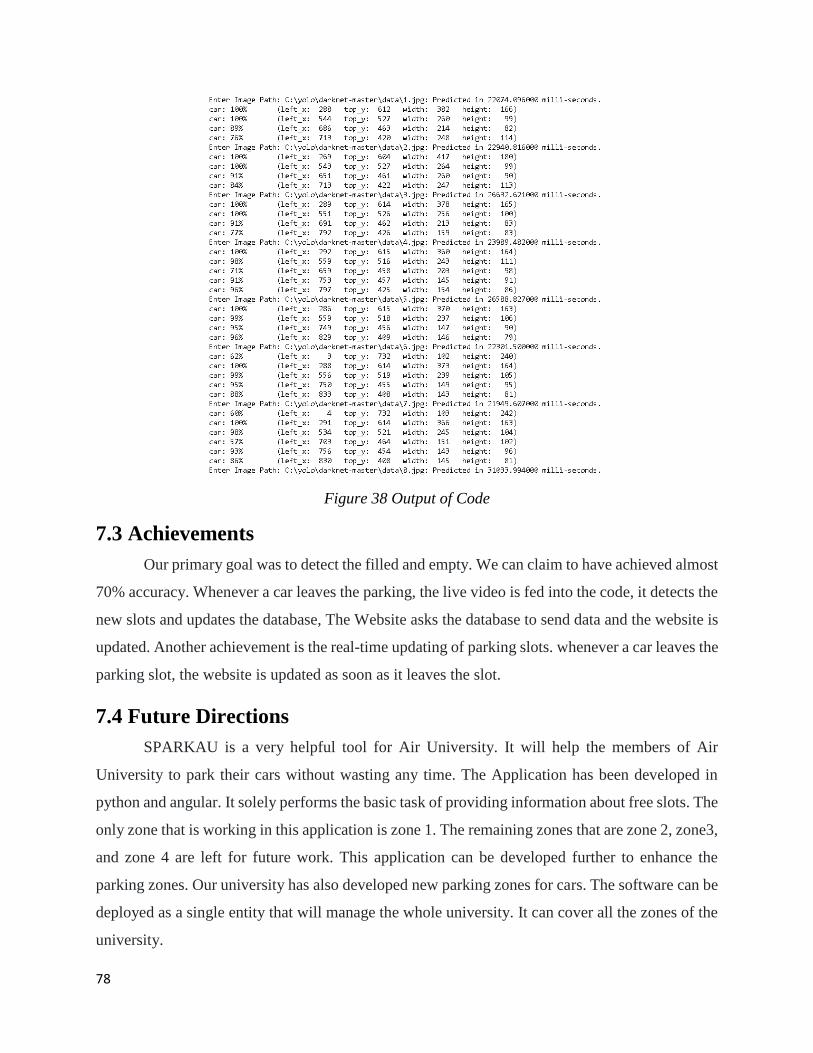
78
Figure 38 Output of Code
7.3 Achievements
Our primary goal was to detect the filled and empty. We can claim to have achieved almost
70% accuracy. Whenever a car leaves the parking, the live video is fed into the code, it detects the
new slots and updates the database, The Website asks the database to send data and the website is
updated. Another achievement is the real-time updating of parking slots. whenever a car leaves the
parking slot, the website is updated as soon as it leaves the slot.
7.4 Future Directions
SPARKAU is a very helpful tool for Air University. It will help the members of Air
University to park their cars without wasting any time. The Application has been developed in
python and angular. It solely performs the basic task of providing information about free slots. The
only zone that is working in this application is zone 1. The remaining zones that are zone 2, zone3,
and zone 4 are left for future work. This application can be developed further to enhance the
parking zones. Our university has also developed new parking zones for cars. The software can be
deployed as a single entity that will manage the whole university. It can cover all the zones of the
university.
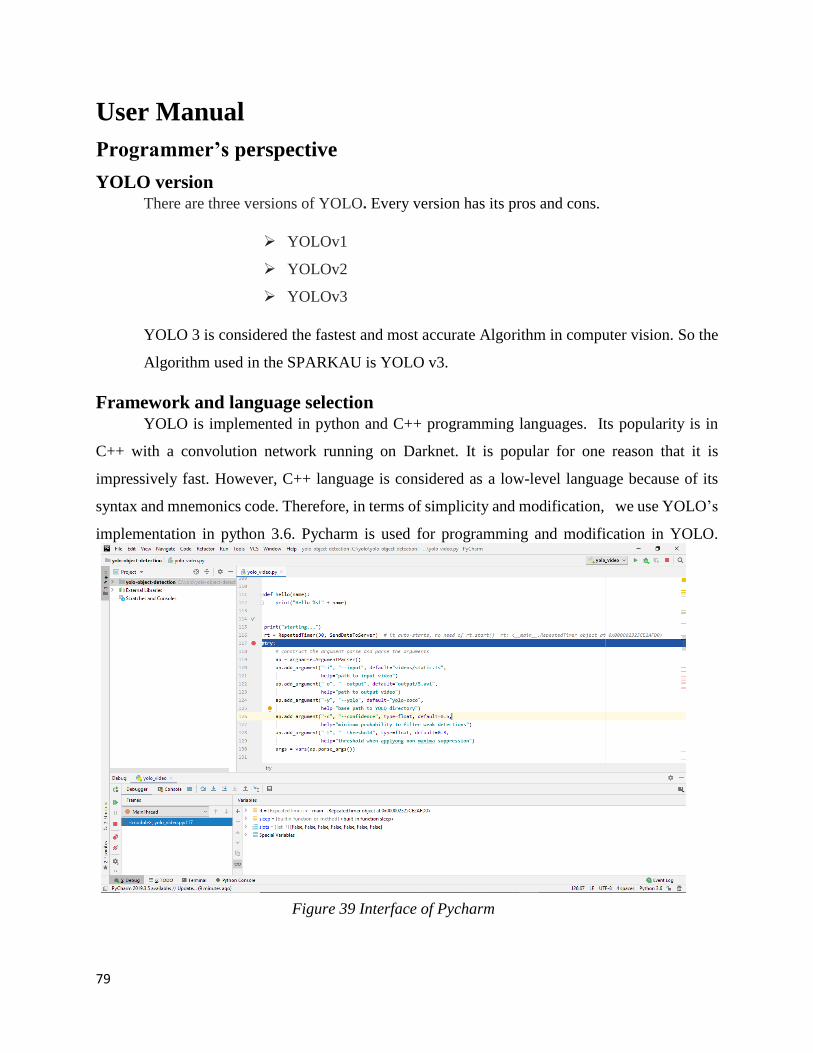
79
User Manual
Programmer’s perspective
YOLO version There are three versions of YOLO. Every version has its pros and cons.
YOLOv1
YOLOv2
YOLOv3
YOLO 3 is considered the fastest and most accurate Algorithm in computer vision. So the
Algorithm used in the SPARKAU is YOLO v3.
Framework and language selection
YOLO is implemented in python and C++ programming languages. Its popularity is in
C++ with a convolution network running on Darknet. It is popular for one reason that it is
impressively fast. However, C++ language is considered as a low-level language because of its
syntax and mnemonics code. Therefore, in terms of simplicity and modification, we use YOLO’s
implementation in python 3.6. Pycharm is used for programming and modification in YOLO.
Figure 39 Interface of Pycharm
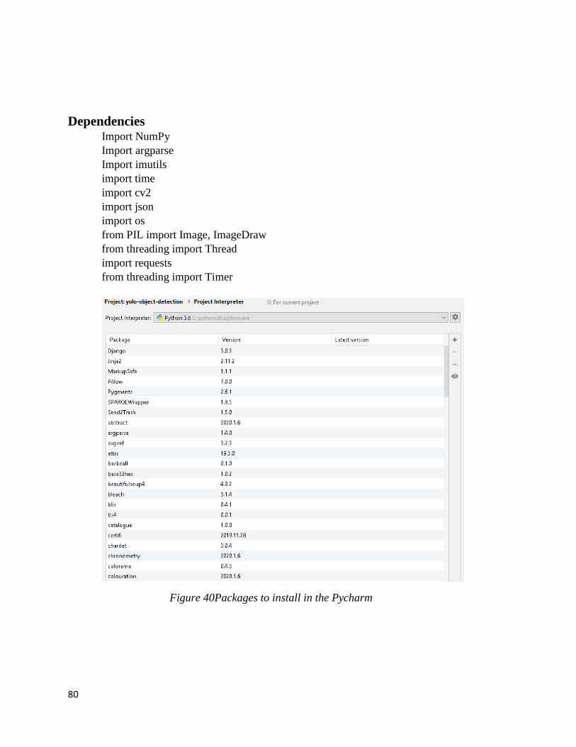
80
Dependencies Import NumPy
Import argparse
Import imutils
import time
import cv2
import json
import os
from PIL import Image, ImageDraw
from threading import Thread
import requests
from threading import Timer
Figure 40Packages to install in the Pycharm
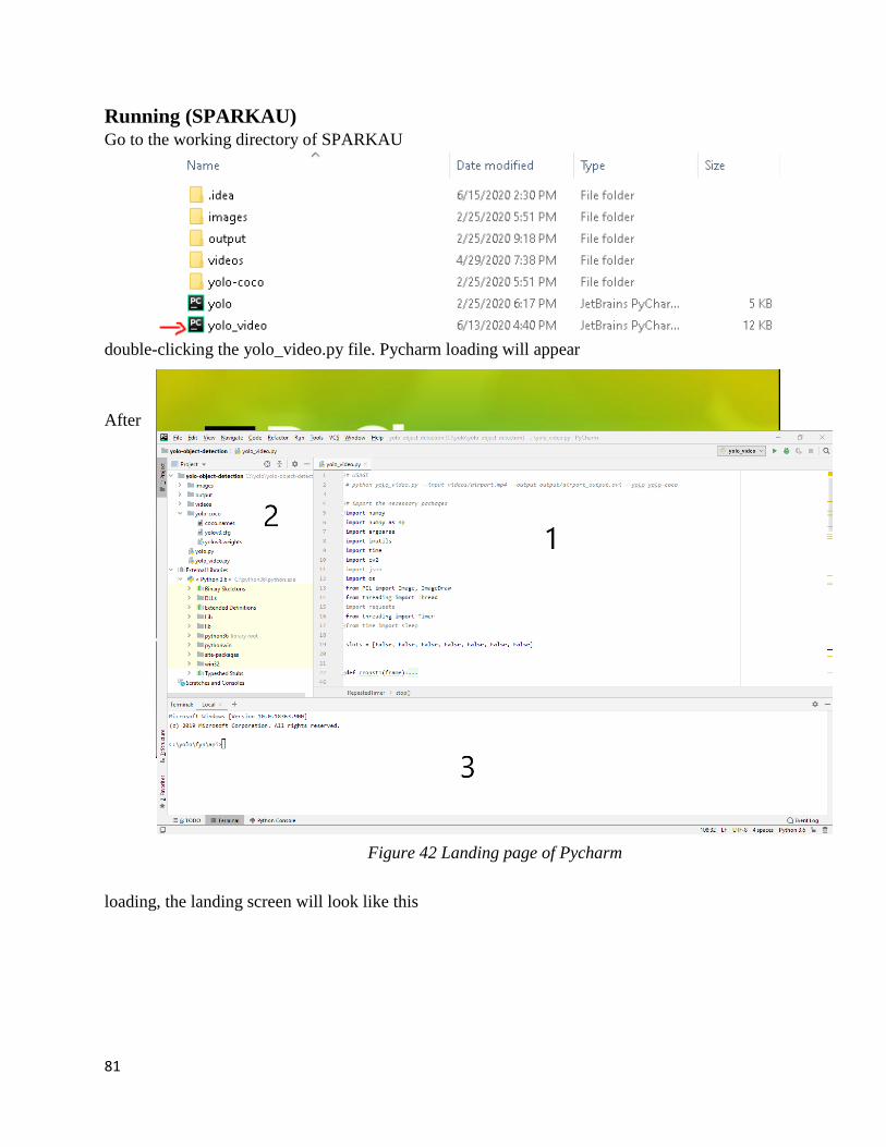
81
Running (SPARKAU) Go to the working directory of SPARKAU
double-clicking the yolo_video.py file. Pycharm loading will appear
After
loading, the landing screen will look like this
Figure 41 Loading Pycharm
Figure 42 Landing page of Pycharm
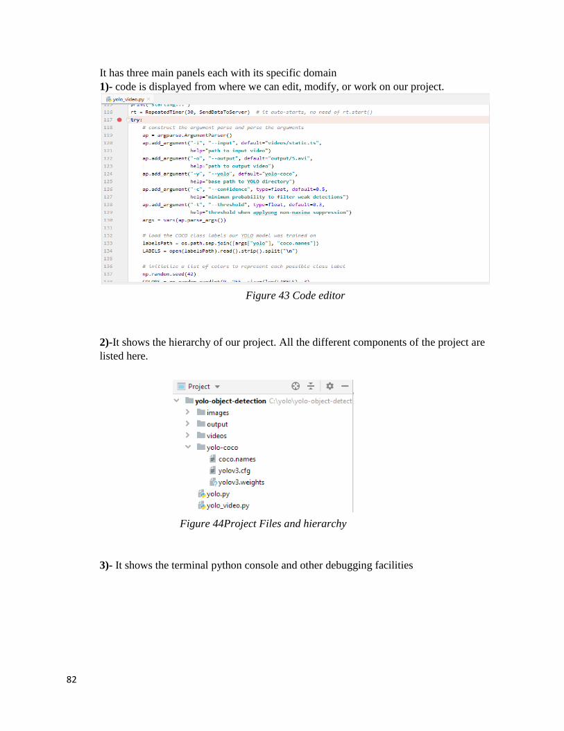
82
It has three main panels each with its specific domain
1)- code is displayed from where we can edit, modify, or work on our project.
2)-It shows the hierarchy of our project. All the different components of the project are
listed here.
3)- It shows the terminal python console and other debugging facilities
Figure 43 Code editor
Figure 44Project Files and hierarchy
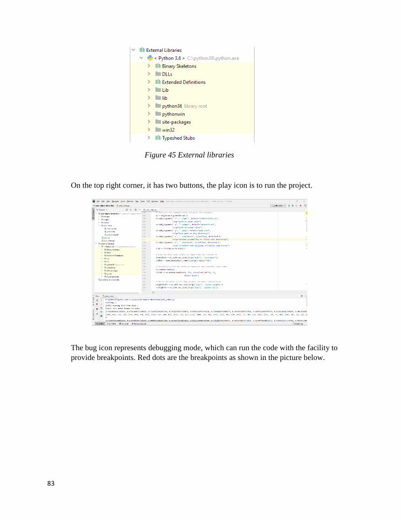
83
On the top right corner, it has two buttons, the play icon is to run the project.
The bug icon represents debugging mode, which can run the code with the facility to
provide breakpoints. Red dots are the breakpoints as shown in the picture below.
Figure 45 External libraries
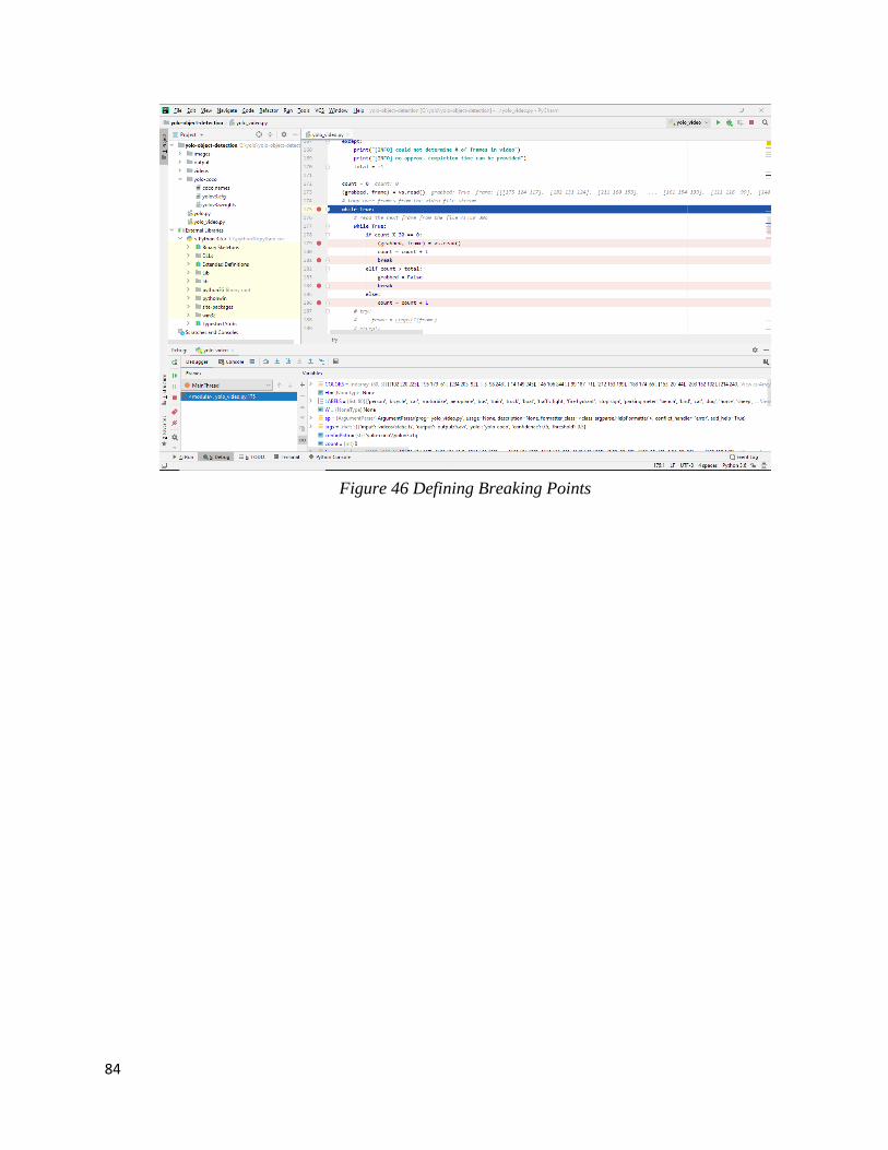
84
Figure 46 Defining Breaking Points
85
User’s perspective
SPARKAU is a smart application that will be used by the students, faculty, and
admin of the air University. The system will help them park their cars without wasting any
time and money. The usage for the user of the GUI is explained in with pictures.
Web Interface To access the web User Interface of the Smart Parking System for Air University.
The user will type the URL on his tablet or laptop to access the website of the SPARKAU.
The website is deployed on the free web hosting site. Everything on this website works
fine. The URL is
http://sparkau.000webhostapp.com
How to use 1
This image is the main home screen for the website of SPARKAU. It has the logo
of the SPARKAU. Below it has four buttons for different zones. Each zone represents the
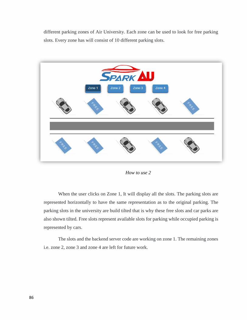
86
different parking zones of Air University. Each zone can be used to look for free parking
slots. Every zone has will consist of 10 different parking slots.
How to use 2
When the user clicks on Zone 1, It will display all the slots. The parking slots are
represented horizontally to have the same representation as to the original parking. The
parking slots in the university are build tilted that is why these free slots and car parks are
also shown tilted. Free slots represent available slots for parking while occupied parking is
represented by cars.
The slots and the backend server code are working on zone 1. The remaining zones
i.e. zone 2, zone 3 and zone 4 are left for future work.
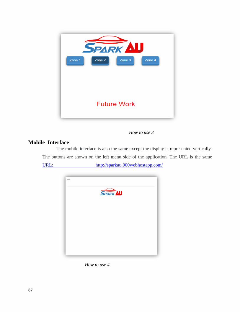
87
How to use 3
Mobile Interface The mobile interface is also the same except the display is represented vertically.
The buttons are shown on the left menu side of the application. The URL is the same
URL: http://sparkau.000webhostapp.com/
How to use 4
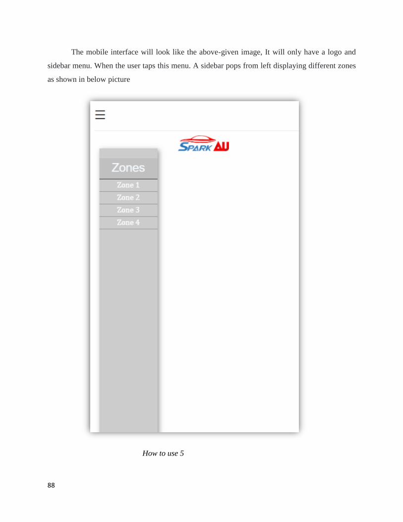
88
The mobile interface will look like the above-given image, It will only have a logo and
sidebar menu. When the user taps this menu. A sidebar pops from left displaying different zones
as shown in below picture
How to use 5
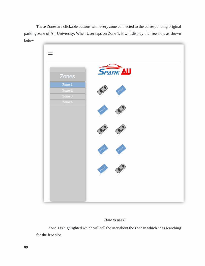
89
These Zones are clickable buttons with every zone connected to the corresponding original
parking zone of Air University. When User taps on Zone 1, it will display the free slots as shown
below
How to use 6
Zone 1 is highlighted which will tell the user about the zone in which he is searching
for the free slot.
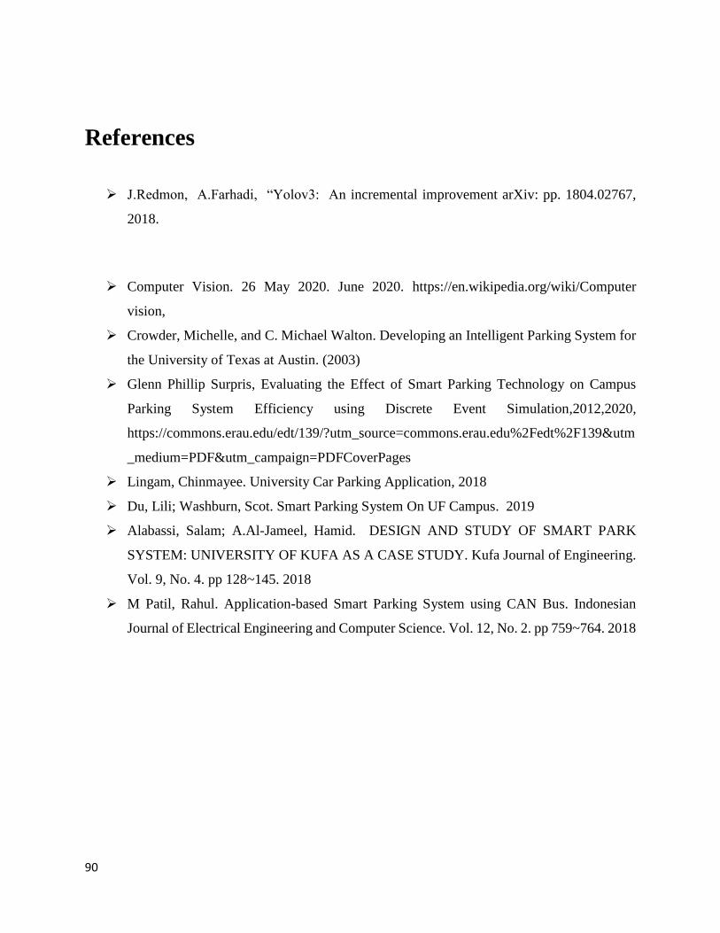
90
References
J.Redmon, A.Farhadi, “Yolov3: An incremental improvement arXiv: pp. 1804.02767,
2018.
Computer Vision. 26 May 2020. June 2020. https://en.wikipedia.org/wiki/Computer
vision,
Crowder, Michelle, and C. Michael Walton. Developing an Intelligent Parking System for
the University of Texas at Austin. (2003)
Glenn Phillip Surpris, Evaluating the Effect of Smart Parking Technology on Campus
Parking System Efficiency using Discrete Event Simulation,2012,2020,
https://commons.erau.edu/edt/139/?utm_source=commons.erau.edu%2Fedt%2F139&utm
_medium=PDF&utm_campaign=PDFCoverPages
Lingam, Chinmayee. University Car Parking Application, 2018
Du, Lili; Washburn, Scot. Smart Parking System On UF Campus. 2019
Alabassi, Salam; A.Al-Jameel, Hamid. DESIGN AND STUDY OF SMART PARK
SYSTEM: UNIVERSITY OF KUFA AS A CASE STUDY. Kufa Journal of Engineering.
Vol. 9, No. 4. pp 128~145. 2018
M Patil, Rahul. Application-based Smart Parking System using CAN Bus. Indonesian
Journal of Electrical Engineering and Computer Science. Vol. 12, No. 2. pp 759~764. 2018