Embed Size (px)
Citation preview
Update of the NIST Smart Grid Conceptual Model (Discussion DRAFT) September 6, 2018 NIST Smart Grid Conceptual Model The NIST Smart Grid Conceptual Model describes the overall composition of electric grid systems and applications. It is meant to provide a high-level view of the system that can be understood by many stakeholders. Originally introduced in the 2010 publication of the first NIST Smart Grid Interoperability Framework, the Conceptual Model is updated with each Framework revision. The Smart Grid Conceptual Model update in this document (see Figure 1) reflects large increases in the number and types of distributed energy resources (DERs) used throughout the grid, the increasing importance and automation of distribution systems, and the role of service providers in the Distribution system.
`` Figure 1- DRAFT Updated NIST Smart Grid Conceptual Model The key concepts derived from the updated Conceptual Model remain broadly similar to those of previous editions. First, that roles and responsibilities for actors and equipment in the electrical grid are a function of the domain in which they are applied. Through this lens we understand that functions required of grid equipment will likely change depending on the grid context, or
Smart Grid Conceptual Model
Markets
Operations
Secure Communication FlowsElectrical Flows
Domain
Service Provider
Transmission
Distribution
Generation including DERSource: DRAFT NIST Smart Grid Framework 4.0
CustomerCustomer
2
domain, in which it is used.1 Benefits associated with equipment, resource, or action will similarly vary with domain and other context. Second, the conceptual model reinforces the contrast between the growing complexity of information exchange necessary to operate the grid, and the relatively straightforward physical exchanges of energy that actually are the grid. Producing or consuming electricity still relies on relatively few and simple physical connections, even as energy technologies diversify across the system and grid dynamics become less certain. Conversely, grid communications and data complexity are exploding as people leverage the proliferation of low-cost power electronics, sensors, and microchips to support grid operations through coordinated actions of small-scale and distributed devices—coordination that was once the exclusive purview of large generators in close physical proximity.2 Whether to expand coordination of the high voltage system3 or to prolong the life of existing distribution infrastructure,4 communication flows are increasing everywhere across the grid. While the high-level concepts contained in the NIST Smart Grid Conceptual Model have proven robust with time, the grid is also changing rapidly. The Conceptual Model and its derivatives have been updated to reflect many changes throughout the system, and explore the associated impact on system interoperability requirements. These changes include:
Generation Domain Changing scale—the domain name has been updated to Generation including DER to explicitly acknowledge the growing diversity in scale and utilization of grid resources. Technology diversity—the number and types of generation technologies has been expanded, to reflect the growing diversity of U.S. generation assets.5 Physical siting—the Generation including DER domain has been elongated, so that icons representing large scale generation technologies are physically closer to the Transmission domain, and smaller scale or more modular technologies are physically closer to the Distribution and Customer domains.
1 For example, a photovoltaic system installed at a single-family house may have significantly different operating parameters than ones installed at commercial facilities or used for bulk power generation. 2 For example, while energy imbalances between supply and demand used to only be managed by dispatching one or two large generators, today the same imbalance could also be addressed through the coordinated actions of many customers and their devices. 3 For example, the Western Energy Imbalance Market (https://www.westerneim.com/pages/default.aspx) 4 For example, the Brooklyn Queens Demand Management Project to defer upgrade of the Brownsville Substations (http://documents.dps.ny.gov/public/Common/ViewDoc.aspx?DocRefId=%7B8FF8D6D6-7E2B-4D83-9B9C-8B3E54612B8C%7D) 5 Annual Energy Outlook 2018 with projections to 2050. U.S. Energy Information Administration, February 6, 2018. https://www.eia.gov/outlooks/aeo/pdf/AEO2018.pdf
3
Distribution Domain Expanding role—the Distribution Domain has been made larger and placed more centrally within the Conceptual Model to reflect the growing responsibilities distribution systems have for optimizing grid function. Improved sensing—sensing in distribution systems (represented by the icon of an overhead line fault detection device) is important to improving state awareness, a prerequisite for optimizing grid function. Controllability and intelligence—computer servers represent the growing availability and use of real-time data for intelligent control of distribution grids. New actors—historically the province of distribution utilities, service providers and other actors are increasingly providing equipment to and services for the distribution grid as indicated by the new link between the Distribution and Service Provider Domains.
Customer Domain Distributed operations—with active energy management possible at the grid edge, operations, control and automation enter the customer domain as represented by the computer monitor replicated from the Operations Domain. Customer diversification—from multi-family dwellings to commercial facilities and campuses, the Customer Domain has been updated to reflect many types of customers served by the electrical grid.
Even with these updates, the high-level Conceptual Model shown in Figure 1 is useful only for exploring the electrical and communications flows between grid domains. Much innovation occurs within the grid domains, the exploration of which improves understanding of the relationships between technology, communications, and interoperability. Underlying the Conceptual Model is a legal and regulatory framework that governs many aspects of the electrical grid. These regulations apply to actors and applications, and to their interactions, throughout the system and enable the implementation and management of policies and requirements that keep the power system safe, reliable and cost effective while maximizing the public good. Organizations that adopt these regulations exist at several levels, from federal agencies to public utility commissions at the state and local levels. The transition to a modern grid introduces new regulatory considerations, which may transcend jurisdictional boundaries and require increased coordination among federal, state, and local lawmakers and regulators. The conceptual model is intended to be a useful tool for regulators at all levels to assess how best to achieve public policy goals that, along with business objectives, motivate investments in modernizing the nation’s electric power infrastructure.
4
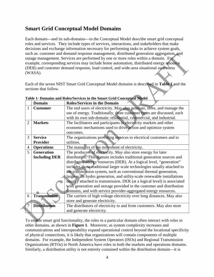
Smart Grid Conceptual Model Domains Each domain—and its sub-domains—in the Conceptual Model describe smart grid conceptual roles and services. They include types of services, interactions, and stakeholders that make decisions and exchange information necessary for performing tasks to achieve system goals, such as: customer and demand response management, distributed generation aggregation, and outage management. Services are performed by one or more roles within a domain. For example, corresponding services may include home automation, distributed energy resource (DER) and customer demand response, load control, and wide-area situational awareness (WASA). Each of the seven NIST Smart Grid Conceptual Model domains is described in Table 1 and the sections that follow. Table 1- Domains and Roles/Services in the Smart Grid Conceptual Model Domain Roles/Services in the Domain 1 Customer The end users of electricity. May also generate, store, and manage the
use of energy. Traditionally, three customer types are discussed, each with its own sub-domain: residential, commercial, and industrial.
2 Markets The facilitators and participants in electricity markets and other economic mechanisms used to drive action and optimize system outcomes.
3 Service Provider
The organizations providing services to electrical customers and to utilities.
4 Operations The managers of the movement of electricity. 5 Generation
Including DER The producers of electricity. May also store energy for later distribution. This domain includes traditional generation sources and distributed energy resources (DER). At a logical level, “generation” includes those traditional larger scale technologies usually attached to the transmission system, such as conventional thermal generation, large-scale hydro generation, and utility-scale renewable installations usually attached to transmission. DER (at a logical level) is associated with generation and storage provided in the customer and distribution domains, and with service provider-aggregated energy resources.
6 Transmission The carriers of high voltage electricity over long distances. May also store and generate electricity.
7 Distribution The distributors of electricity to and from customers. May also store and generate electricity.
To enable smart grid functionality, the roles in a particular domain often interact with roles in other domains, as shown in Figure 1. Moreover, as system complexity increases and communications and interoperability expand operational control beyond the locational specificity of physical connections, it is likely that organizations will contain components of multiple domains. For example, the Independent System Operators (ISOs) and Regional Transmission Organizations (RTOs) in North America have roles in both the markets and operations domains. Similarly, a distribution utility is not entirely contained within the distribution domain—it is
5
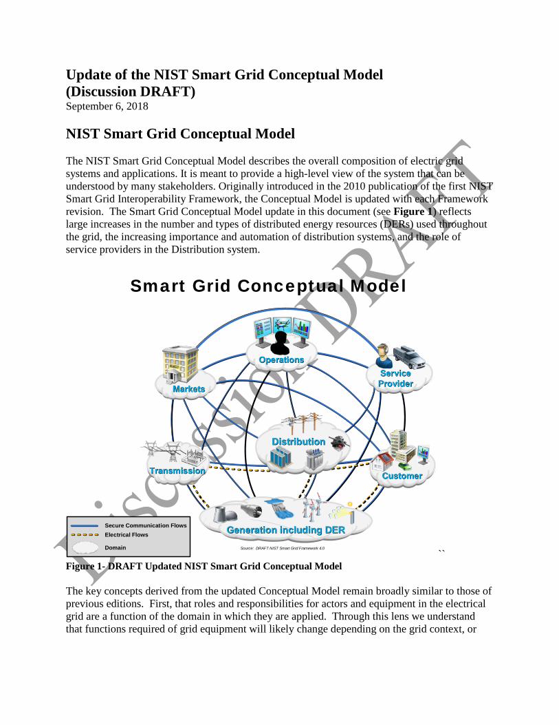
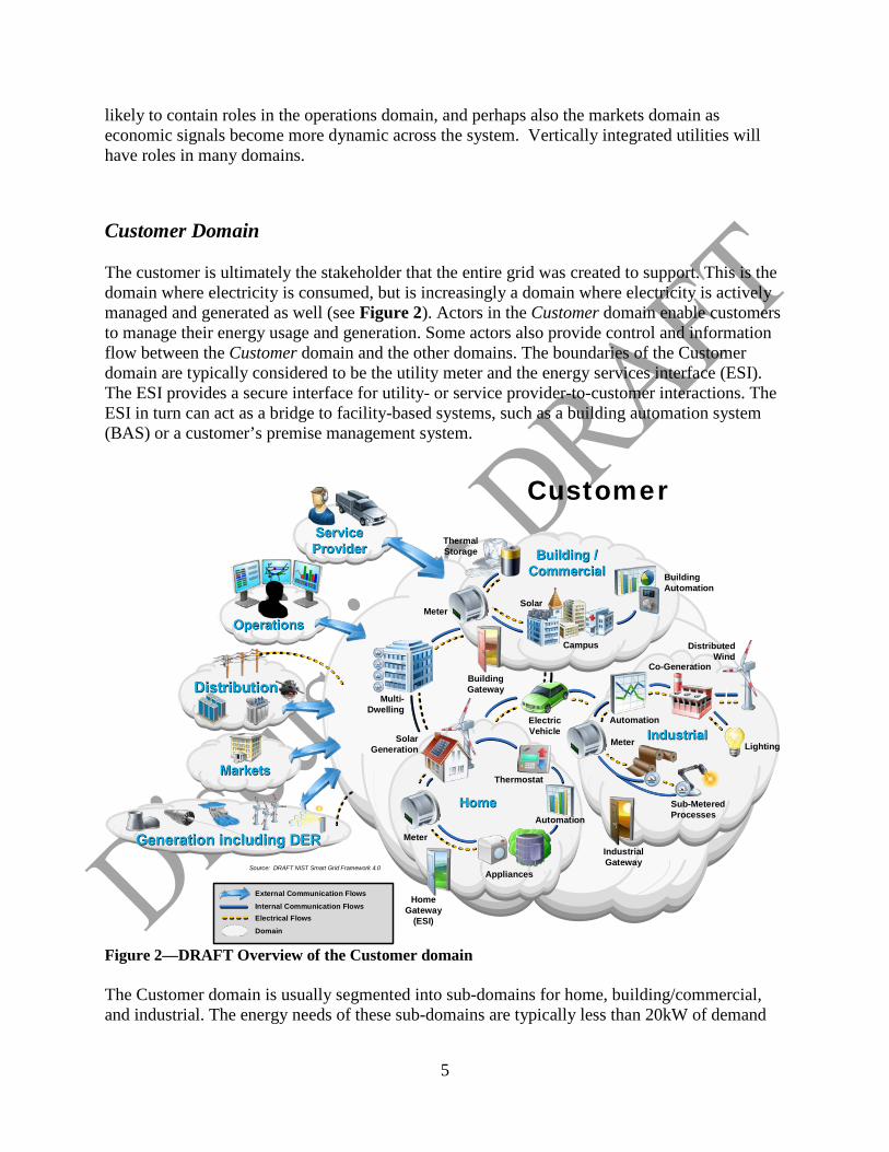
likely to contain roles in the operations domain, and perhaps also the markets domain as economic signals become more dynamic across the system. Vertically integrated utilities will have roles in many domains. Customer Domain The customer is ultimately the stakeholder that the entire grid was created to support. This is the domain where electricity is consumed, but is increasingly a domain where electricity is actively managed and generated as well (see Figure 2). Actors in the Customer domain enable customers to manage their energy usage and generation. Some actors also provide control and information flow between the Customer domain and the other domains. The boundaries of the Customer domain are typically considered to be the utility meter and the energy services interface (ESI). The ESI provides a secure interface for utility- or service provider-to-customer interactions. The ESI in turn can act as a bridge to facility-based systems, such as a building automation system (BAS) or a customer’s premise management system.
Figure 2—DRAFT Overview of the Customer domain The Customer domain is usually segmented into sub-domains for home, building/commercial, and industrial. The energy needs of these sub-domains are typically less than 20kW of demand
Distribution
Thermal Storage
Customer
Operations
Markets
Building / Commercial
Home
Industrial
Distributed Wind
Co-Generation
Lighting
Sub-Metered Processes
Meter
Industrial Gateway
Appliances
Automation
Thermostat
Home Gateway
(ESI)
Meter
Solar Generation
Multi- Dwelling
Meter
Building Gateway
Electric Vehicle
Campus
Solar
Building Automation
Automation
Source: DRAFT NIST Smart Grid Framework 4.0
Generation including DER
Service Provider
Internal Communication FlowsElectrical FlowsDomain
External Communication Flows
6
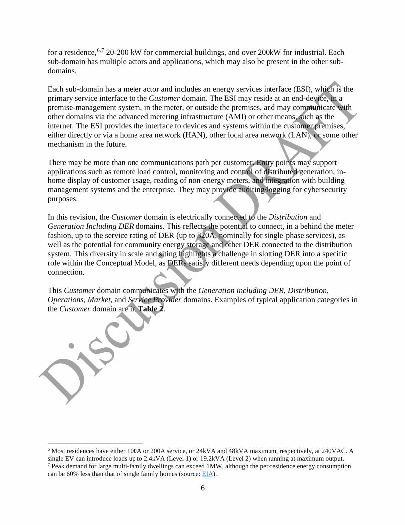
for a residence,6,7 20-200 kW for commercial buildings, and over 200kW for industrial. Each sub-domain has multiple actors and applications, which may also be present in the other sub-domains. Each sub-domain has a meter actor and includes an energy services interface (ESI), which is the primary service interface to the Customer domain. The ESI may reside at an end-device, in a premise-management system, in the meter, or outside the premises, and may communicate with other domains via the advanced metering infrastructure (AMI) or other means, such as the internet. The ESI provides the interface to devices and systems within the customer premises, either directly or via a home area network (HAN), other local area network (LAN), or some other mechanism in the future. There may be more than one communications path per customer. Entry points may support applications such as remote load control, monitoring and control of distributed generation, in-home display of customer usage, reading of non-energy meters, and integration with building management systems and the enterprise. They may provide auditing/logging for cybersecurity purposes. In this revision, the Customer domain is electrically connected to the Distribution and Generation Including DER domains. This reflects the potential to connect, in a behind the meter fashion, up to the service rating of DER (up to 320A, nominally for single-phase services), as well as the potential for community energy storage and other DER connected to the distribution system. This diversity in scale and siting highlights a challenge in slotting DER into a specific role within the Conceptual Model, as DERs satisfy different needs depending upon the point of connection. This Customer domain communicates with the Generation including DER, Distribution, Operations, Market, and Service Provider domains. Examples of typical application categories in the Customer domain are in Table 2.
6 Most residences have either 100A or 200A service, or 24kVA and 48kVA maximum, respectively, at 240VAC. A single EV can introduce loads up to 2.4kVA (Level 1) or 19.2kVA (Level 2) when running at maximum output. 7 Peak demand for large multi-family dwellings can exceed 1MW, although the per-residence energy consumption can be 60% less than that of single family homes (source: EIA).
7
Table 2—Typical application categories in the Customer domain Example Application Category Description
Building or Home Automation
A system that is capable of controlling various functions within a building, such as lighting, temperature control and appliance usage.
Industrial Automation
A system that controls industrial processes such as manufacturing or warehousing. These systems have very different requirements compared to home and building systems.
Micro-generation
Includes all types of distributed generation including: solar, wind, and hydroelectric generators. This generation harnesses energy for electricity at a customer location. May be monitored, dispatched, or controlled via communications.
Storage Means to store energy that may be converted directly or through a process to electricity. Examples include thermal storage units, and batteries (both stationary and electric vehicles)
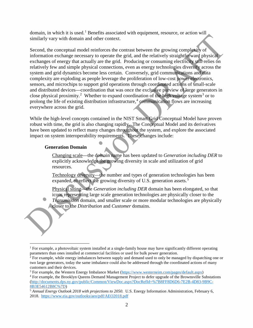
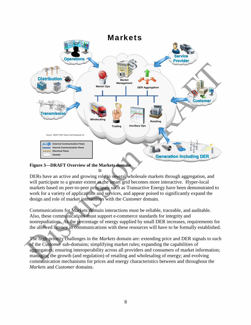
Markets Domain The markets are where grid assets and services are bought and sold. Markets yet to be created may be instrumental in defining the smart grid of the future, particularly with DER and aggregated DER. Entities in the Markets domain exchange price and balance supply and demand within the power system (see Figure 3). The boundaries of the Markets domain include the edge of the Operations domain where control happens, the domains supplying assets (Generation including DER, Transmission, and Distribution), the Service Provider domain, and the Customer domain. In short, the Markets domain interfaces with all domains of the smart grid. Communication flows between the Markets domain and the domains supplying energy are critical because efficient matching of production with consumption is dependent on markets. Energy supply domains include the Generation Including DER—and more recently the Customer—domains. The North American Electric Reliability Corporation (NERC) Critical Infrastructure Protections (CIP) standards consider suppliers of more than 300 megawatts to be bulk generation; most DER is smaller and is typically served through aggregators.
8
Figure 3—DRAFT Overview of the Markets domain DERs have an active and growing role in several wholesale markets through aggregation, and will participate to a greater extent as the smart grid becomes more interactive. Hyper-local markets based on peer-to-peer principals such as Transactive Energy have been demonstrated to work for a variety of applications and services, and appear poised to significantly expand the design and role of market interactions with the Customer domain. Communications for Markets domain interactions must be reliable, traceable, and auditable. Also, these communications must support e-commerce standards for integrity and nonrepudiation. As the percentage of energy supplied by small DER increases, requirements for the allowed latency in communications with these resources will have to be formally established. The high-priority challenges in the Markets domain are: extending price and DER signals to each of the Customer sub-domains; simplifying market rules; expanding the capabilities of aggregators; ensuring interoperability across all providers and consumers of market information; managing the growth (and regulation) of retailing and wholesaling of energy; and evolving communication mechanisms for prices and energy characteristics between and throughout the Markets and Customer domains.
Distribution
Markets
Operations
Market Management
Market Ops
Ancillary OpsTrading
Wholesaling
DER Aggregation
Retailing
Internal Communication FlowsElectrical FlowsDomain
External Communication Flows
Source: DRAFT NIST Smart Grid Framework 4.0
Generation including DER
Transmission
Service Provider
CustomerCustomer
9
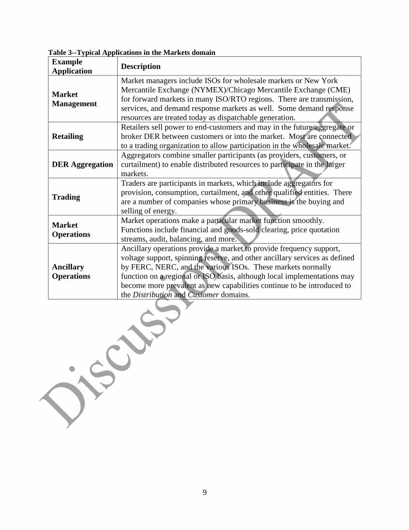
Table 3--Typical Applications in the Markets domain Example Application Description
Market Management
Market managers include ISOs for wholesale markets or New York Mercantile Exchange (NYMEX)/Chicago Mercantile Exchange (CME) for forward markets in many ISO/RTO regions. There are transmission, services, and demand response markets as well. Some demand response resources are treated today as dispatchable generation.
Retailing Retailers sell power to end-customers and may in the future aggregate or broker DER between customers or into the market. Most are connected to a trading organization to allow participation in the wholesale market.
DER Aggregation Aggregators combine smaller participants (as providers, customers, or curtailment) to enable distributed resources to participate in the larger markets.
Trading
Traders are participants in markets, which include aggregators for provision, consumption, curtailment, and other qualified entities. There are a number of companies whose primary business is the buying and selling of energy.
Market Operations
Market operations make a particular market function smoothly. Functions include financial and goods-sold clearing, price quotation streams, audit, balancing, and more.
Ancillary Operations
Ancillary operations provide a market to provide frequency support, voltage support, spinning reserve, and other ancillary services as defined by FERC, NERC, and the various ISOs. These markets normally function on a regional or ISO basis, although local implementations may become more prevalent as new capabilities continue to be introduced to the Distribution and Customer domains.
10
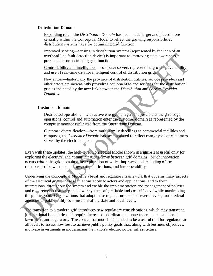
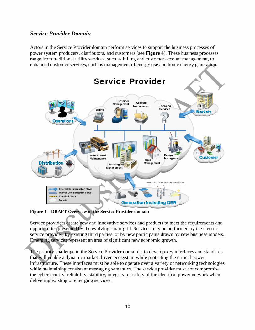
Service Provider Domain Actors in the Service Provider domain perform services to support the business processes of power system producers, distributors, and customers (see Figure 4). These business processes range from traditional utility services, such as billing and customer account management, to enhanced customer services, such as management of energy use and home energy generation.
Figure 4—DRAFT Overview of the Service Provider domain Service providers create new and innovative services and products to meet the requirements and opportunities presented by the evolving smart grid. Services may be performed by the electric service provider, by existing third parties, or by new participants drawn by new business models. Emerging services represent an area of significant new economic growth. The priority challenge in the Service Provider domain is to develop key interfaces and standards that will enable a dynamic market-driven ecosystem while protecting the critical power infrastructure. These interfaces must be able to operate over a variety of networking technologies while maintaining consistent messaging semantics. The service provider must not compromise the cybersecurity, reliability, stability, integrity, or safety of the electrical power network when delivering existing or emerging services.
Distribution
EmergingServicesBilling
CustomerManagement
BuildingManagement
Installation &Maintenance Home
Management
AccountManagement
Markets
Service Provider
Operations
Internal Communication FlowsElectrical FlowsDomain
External Communication Flows
Source: DRAFT NIST Smart Grid Framework 4.0
Generation including DER
CustomerCustomerEnergyManagement
11
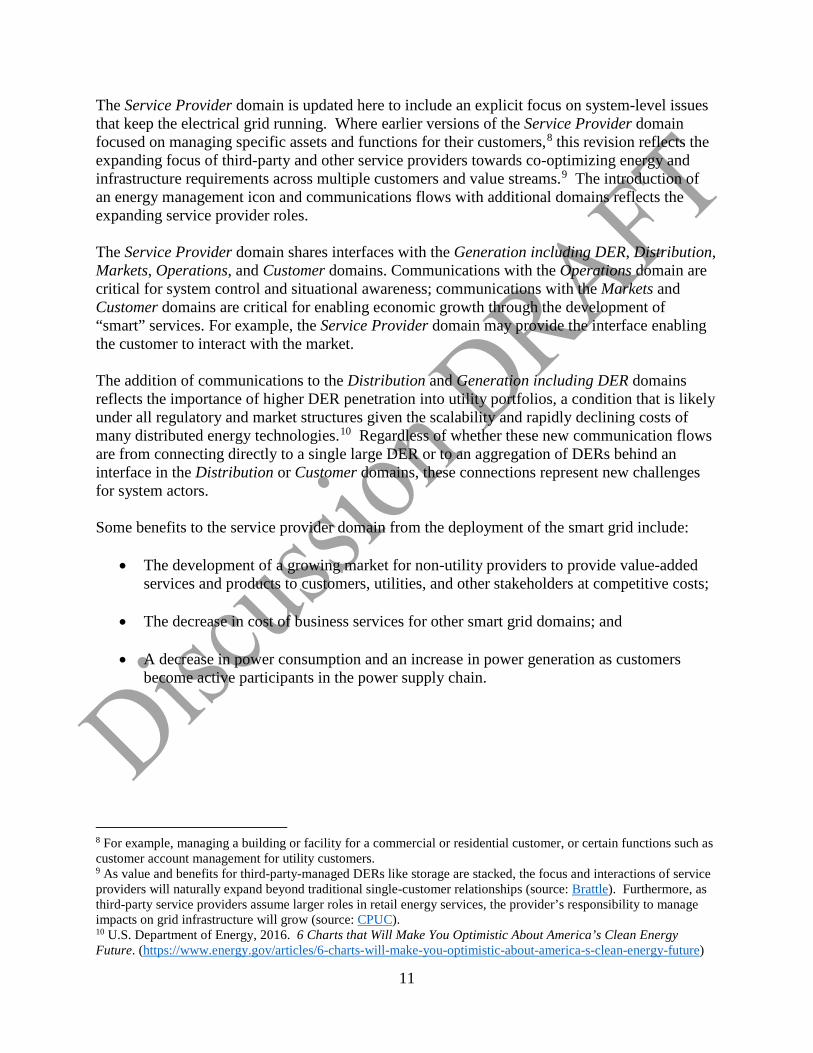
The Service Provider domain is updated here to include an explicit focus on system-level issues that keep the electrical grid running. Where earlier versions of the Service Provider domain focused on managing specific assets and functions for their customers,8 this revision reflects the expanding focus of third-party and other service providers towards co-optimizing energy and infrastructure requirements across multiple customers and value streams.9 The introduction of an energy management icon and communications flows with additional domains reflects the expanding service provider roles. The Service Provider domain shares interfaces with the Generation including DER, Distribution, Markets, Operations, and Customer domains. Communications with the Operations domain are critical for system control and situational awareness; communications with the Markets and Customer domains are critical for enabling economic growth through the development of “smart” services. For example, the Service Provider domain may provide the interface enabling the customer to interact with the market. The addition of communications to the Distribution and Generation including DER domains reflects the importance of higher DER penetration into utility portfolios, a condition that is likely under all regulatory and market structures given the scalability and rapidly declining costs of many distributed energy technologies.10 Regardless of whether these new communication flows are from connecting directly to a single large DER or to an aggregation of DERs behind an interface in the Distribution or Customer domains, these connections represent new challenges for system actors. Some benefits to the service provider domain from the deployment of the smart grid include:
• The development of a growing market for non-utility providers to provide value-added services and products to customers, utilities, and other stakeholders at competitive costs;
• The decrease in cost of business services for other smart grid domains; and
• A decrease in power consumption and an increase in power generation as customers
become active participants in the power supply chain.
8 For example, managing a building or facility for a commercial or residential customer, or certain functions such as customer account management for utility customers. 9 As value and benefits for third-party-managed DERs like storage are stacked, the focus and interactions of service providers will naturally expand beyond traditional single-customer relationships (source: Brattle). Furthermore, as third-party service providers assume larger roles in retail energy services, the provider’s responsibility to manage impacts on grid infrastructure will grow (source: CPUC). 10 U.S. Department of Energy, 2016. 6 Charts that Will Make You Optimistic About America’s Clean Energy Future. (https://www.energy.gov/articles/6-charts-will-make-you-optimistic-about-america-s-clean-energy-future)
12
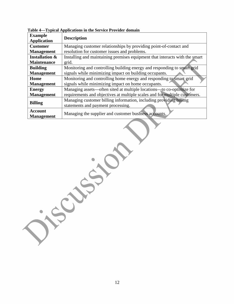
Table 4—Typical Applications in the Service Provider domain Example Application Description
Customer Management
Managing customer relationships by providing point-of-contact and resolution for customer issues and problems.
Installation & Maintenance
Installing and maintaining premises equipment that interacts with the smart grid.
Building Management
Monitoring and controlling building energy and responding to smart grid signals while minimizing impact on building occupants.
Home Management
Monitoring and controlling home energy and responding to smart grid signals while minimizing impact on home occupants.
Energy Management
Managing assets—often sited at multiple locations—to co-optimize for requirements and objectives at multiple scales and for multiple customers.
Billing Managing customer billing information, including providing billing statements and payment processing.
Account Management Managing the supplier and customer business accounts.
13
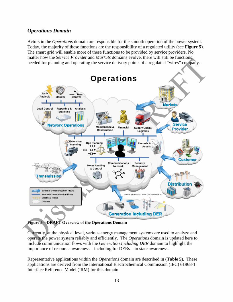
Operations Domain Actors in the Operations domain are responsible for the smooth operation of the power system. Today, the majority of these functions are the responsibility of a regulated utility (see Figure 5). The smart grid will enable more of these functions to be provided by service providers. No matter how the Service Provider and Markets domains evolve, there will still be functions needed for planning and operating the service delivery points of a regulated “wires” company.
Figure 5—DRAFT Overview of the Operations Domain Currently, at the physical level, various energy management systems are used to analyze and operate the power system reliably and efficiently. The Operations domain is updated here to include communication flows with the Generation Including DER domain to highlight the importance of resource awareness—including for DERs—in state awareness. Representative applications within the Operations domain are described in (Table 5). These applications are derived from the International Electrochemical Commission (IEC) 61968-1 Interface Reference Model (IRM) for this domain.
Distribution
Supply Chain / Logistics
Maintenance & Construction
Meter Reading & Control
Communications Network
Operations
Financial
Records & Assets
Ops PlanningExtension Planning
Network Operations
AnalysisReporting & Statistics
Load Control
ControlMonitorFault
Analysis
Markets
Security Management
Internal Communication FlowsElectrical FlowsDomain
External Communication FlowsSource: DRAFT NIST Smart Grid Framework 4.0
Transmission
Generation including DER
Service Provider
CustomerCustomer
14
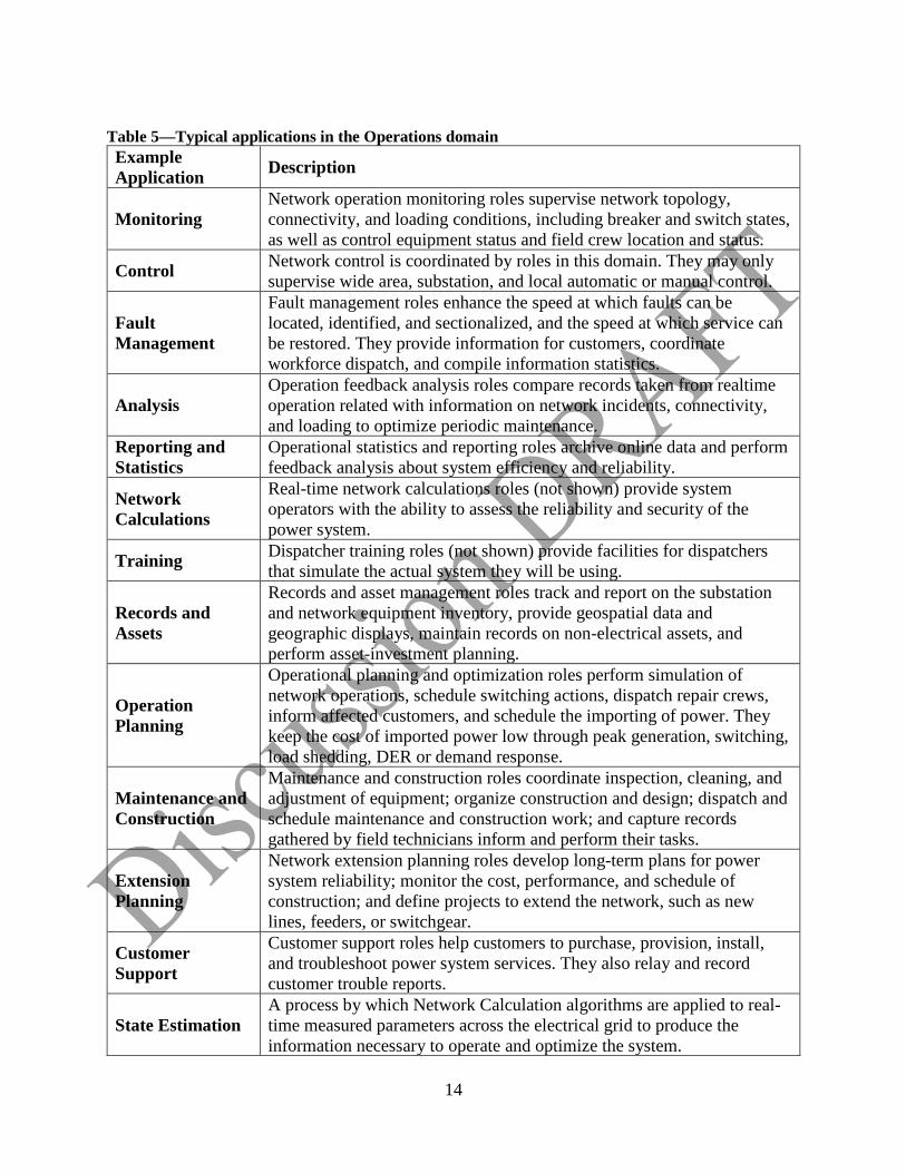
Table 5—Typical applications in the Operations domain Example Application Description
Monitoring Network operation monitoring roles supervise network topology, connectivity, and loading conditions, including breaker and switch states, as well as control equipment status and field crew location and status.
Control Network control is coordinated by roles in this domain. They may only supervise wide area, substation, and local automatic or manual control.
Fault Management
Fault management roles enhance the speed at which faults can be located, identified, and sectionalized, and the speed at which service can be restored. They provide information for customers, coordinate workforce dispatch, and compile information statistics.
Analysis Operation feedback analysis roles compare records taken from realtime operation related with information on network incidents, connectivity, and loading to optimize periodic maintenance.
Reporting and Statistics
Operational statistics and reporting roles archive online data and perform feedback analysis about system efficiency and reliability.
Network Calculations
Real-time network calculations roles (not shown) provide system operators with the ability to assess the reliability and security of the power system.
Training Dispatcher training roles (not shown) provide facilities for dispatchers that simulate the actual system they will be using.
Records and Assets
Records and asset management roles track and report on the substation and network equipment inventory, provide geospatial data and geographic displays, maintain records on non-electrical assets, and perform asset-investment planning.
Operation Planning
Operational planning and optimization roles perform simulation of network operations, schedule switching actions, dispatch repair crews, inform affected customers, and schedule the importing of power. They keep the cost of imported power low through peak generation, switching, load shedding, DER or demand response.
Maintenance and Construction
Maintenance and construction roles coordinate inspection, cleaning, and adjustment of equipment; organize construction and design; dispatch and schedule maintenance and construction work; and capture records gathered by field technicians inform and perform their tasks.
Extension Planning
Network extension planning roles develop long-term plans for power system reliability; monitor the cost, performance, and schedule of construction; and define projects to extend the network, such as new lines, feeders, or switchgear.
Customer Support
Customer support roles help customers to purchase, provision, install, and troubleshoot power system services. They also relay and record customer trouble reports.
State Estimation A process by which Network Calculation algorithms are applied to real-time measured parameters across the electrical grid to produce the information necessary to operate and optimize the system.
15
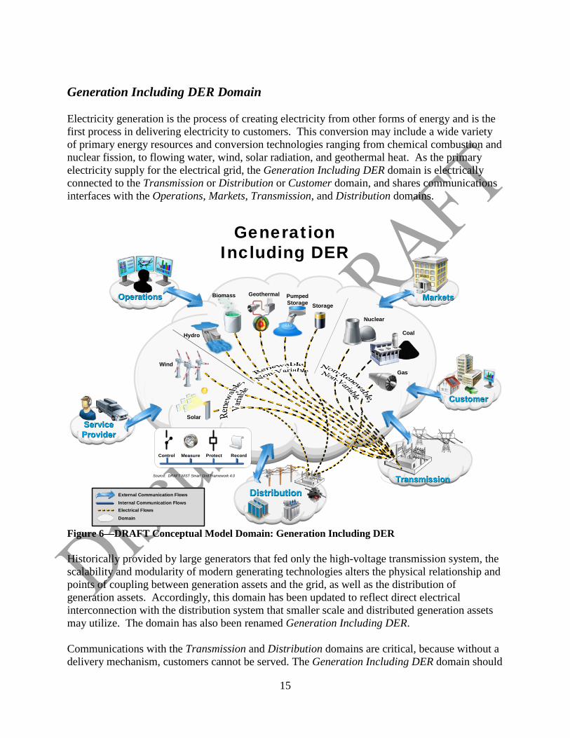
Generation Including DER Domain Electricity generation is the process of creating electricity from other forms of energy and is the first process in delivering electricity to customers. This conversion may include a wide variety of primary energy resources and conversion technologies ranging from chemical combustion and nuclear fission, to flowing water, wind, solar radiation, and geothermal heat. As the primary electricity supply for the electrical grid, the Generation Including DER domain is electrically connected to the Transmission or Distribution or Customer domain, and shares communications interfaces with the Operations, Markets, Transmission, and Distribution domains.
Figure 6—DRAFT Conceptual Model Domain: Generation Including DER Historically provided by large generators that fed only the high-voltage transmission system, the scalability and modularity of modern generating technologies alters the physical relationship and points of coupling between generation assets and the grid, as well as the distribution of generation assets. Accordingly, this domain has been updated to reflect direct electrical interconnection with the distribution system that smaller scale and distributed generation assets may utilize. The domain has also been renamed Generation Including DER. Communications with the Transmission and Distribution domains are critical, because without a delivery mechanism, customers cannot be served. The Generation Including DER domain should
Distribution
GenerationIncluding DER
Transmission
MarketsOperations
Wind
Hydro Coal
Solar
Nuclear
Gas
Geothermal PumpedStorage
Biomass
Control Measure Protect
Record
Internal Communication FlowsElectrical FlowsDomain
External Communication Flows
Storage
Source: DRAFT NIST Smart Grid Framework 4.0
Service Provider
CustomerCustomer
16
communicate key performance and quality of service issues such as scarcity and generator failure. These communications may cause the routing of electricity from other sources. A lack of sufficient supply is addressed directly (via Operations) or indirectly (via Markets). Communication are extremely critical to the increasingly pervasive DER at the bulk system and distribution levels, including behind-the-meter installations. The Generation Including DER domain has therefore been updated in this revision to explicitly identify necessary communications flows with the Distribution, Customer, and Service Provider domains. These external communications flows (shown as bidirectional arrows in Figure 6) represent the inter-domain communications flows previously drawn in Figure 1, and are not intended to describe specific interactions among roles or actors. Evolving requirements for the Generation Including DER domain may include priorities such as controls for greenhouse gas emissions,11 increases in renewable energy sources,12 and provision of storage13 to manage the variability of renewable generation or defer infrastructure obsolescence. To the extent that some of these goals require coordination across multiple domains, this complexity and associated interoperability requirements can be examined through the Conceptual Model communications flows. Roles in the Generation Including DER domain may include various physical actors, such as protection relays, remote terminal units, equipment monitors, fault recorders, user interfaces, and programmable logic controllers. For this revision, NIST has not included demand response, energy efficiency, or other load management technologies in the Generation Including DER domain. While many market structures treat demand management similar to generating capacity14 and/or energy production,15 in the NIST conceptual model those capabilities are maintained within the Customer domain, while the Generation Including DER domain maintains a focus on electron production and interconnection. Examples of typical functions within the Generation Including DER domain that depend on communications flows and require interoperability are shown in Table 6.
11 For example, The Regional Greenhouse Gas Initiative (https://www.rggi.org/) 12 See Database of State Incentives for Renewables & Efficiency (DSIRE) at http://www.dsireusa.org/ 13 See California Public Utilities Commission Rulemaking 15-03-011 (http://docs.cpuc.ca.gov/PublishedDocs/Published/G000/M149/K976/149976766.PDF) 14 For example, PJM’s 2019/2020 Reliability Pricing Model Base Residual Auction Results (https://www.pjm.com/~/media/markets-ops/rpm/rpm-auction-info/2019-2020-base-residual-auction-report.ashx) 15 Smart Electric Power Alliance, 2017 Utility Demand Response Market Snapshot. (https://sepapower.org/resource/2017-utility-demand-response-market-snapshot/)
17
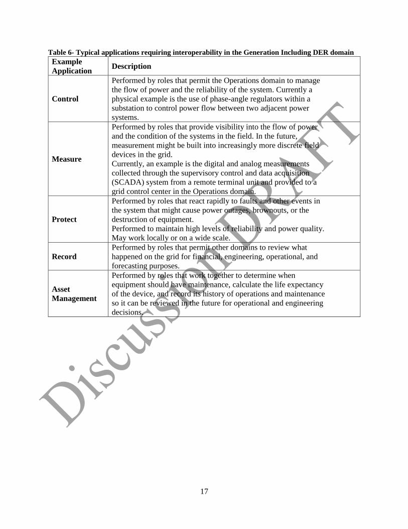
Table 6- Typical applications requiring interoperability in the Generation Including DER domain Example Application Description
Control
Performed by roles that permit the Operations domain to manage the flow of power and the reliability of the system. Currently a physical example is the use of phase-angle regulators within a substation to control power flow between two adjacent power systems.
Measure
Performed by roles that provide visibility into the flow of power and the condition of the systems in the field. In the future, measurement might be built into increasingly more discrete field devices in the grid. Currently, an example is the digital and analog measurements collected through the supervisory control and data acquisition (SCADA) system from a remote terminal unit and provided to a grid control center in the Operations domain.
Protect
Performed by roles that react rapidly to faults and other events in the system that might cause power outages, brownouts, or the destruction of equipment. Performed to maintain high levels of reliability and power quality. May work locally or on a wide scale.
Record Performed by roles that permit other domains to review what happened on the grid for financial, engineering, operational, and forecasting purposes.
Asset Management
Performed by roles that work together to determine when equipment should have maintenance, calculate the life expectancy of the device, and record its history of operations and maintenance so it can be reviewed in the future for operational and engineering decisions.
18
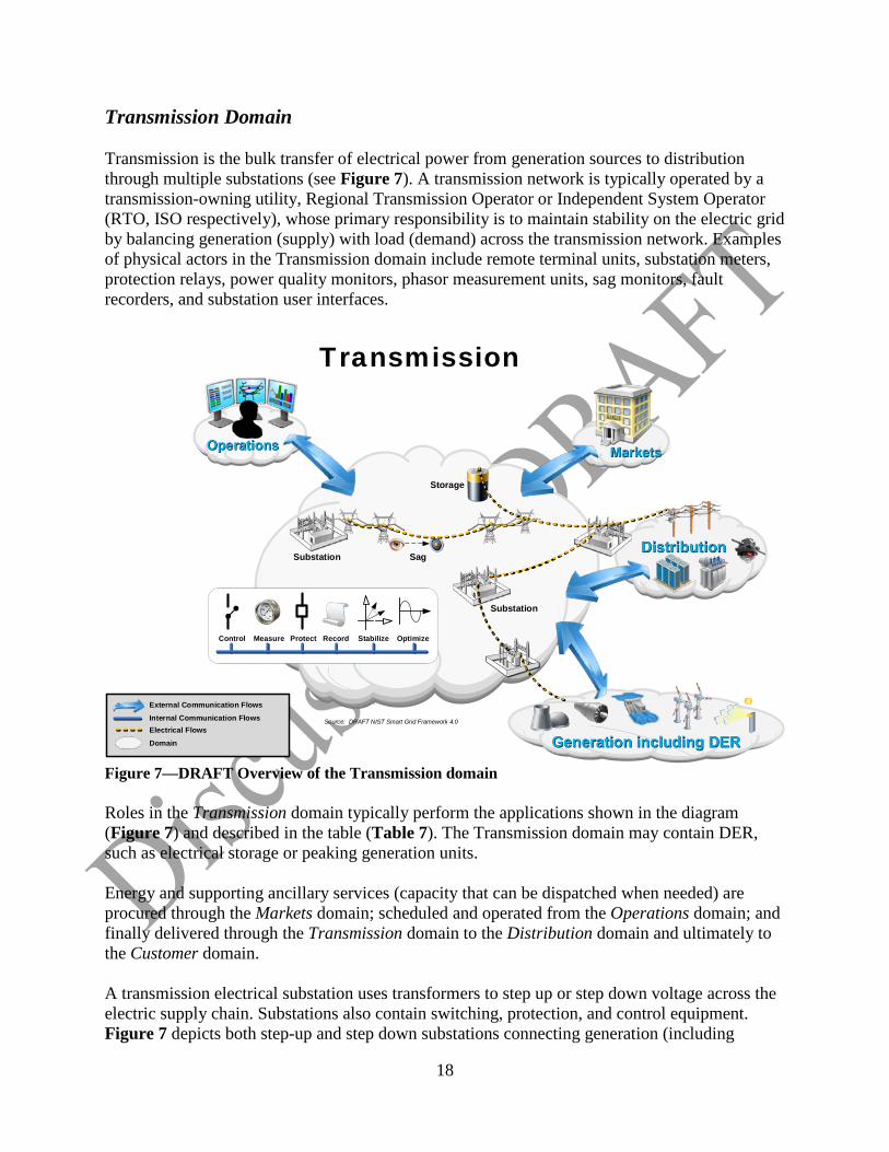
Transmission Domain Transmission is the bulk transfer of electrical power from generation sources to distribution through multiple substations (see Figure 7). A transmission network is typically operated by a transmission-owning utility, Regional Transmission Operator or Independent System Operator (RTO, ISO respectively), whose primary responsibility is to maintain stability on the electric grid by balancing generation (supply) with load (demand) across the transmission network. Examples of physical actors in the Transmission domain include remote terminal units, substation meters, protection relays, power quality monitors, phasor measurement units, sag monitors, fault recorders, and substation user interfaces.
Figure 7—DRAFT Overview of the Transmission domain Roles in the Transmission domain typically perform the applications shown in the diagram (Figure 7) and described in the table (Table 7). The Transmission domain may contain DER, such as electrical storage or peaking generation units. Energy and supporting ancillary services (capacity that can be dispatched when needed) are procured through the Markets domain; scheduled and operated from the Operations domain; and finally delivered through the Transmission domain to the Distribution domain and ultimately to the Customer domain. A transmission electrical substation uses transformers to step up or step down voltage across the electric supply chain. Substations also contain switching, protection, and control equipment. Figure 7 depicts both step-up and step down substations connecting generation (including
Distribution
Storage
Substation Sag
Transmission
Substation
Control
Measure Protect Record Stabilize Optimize
Operations Markets
Internal Communication FlowsElectrical FlowsDomain
External Communication Flows
Source: DRAFT NIST Smart Grid Framework 4.0
Generation including DER
19
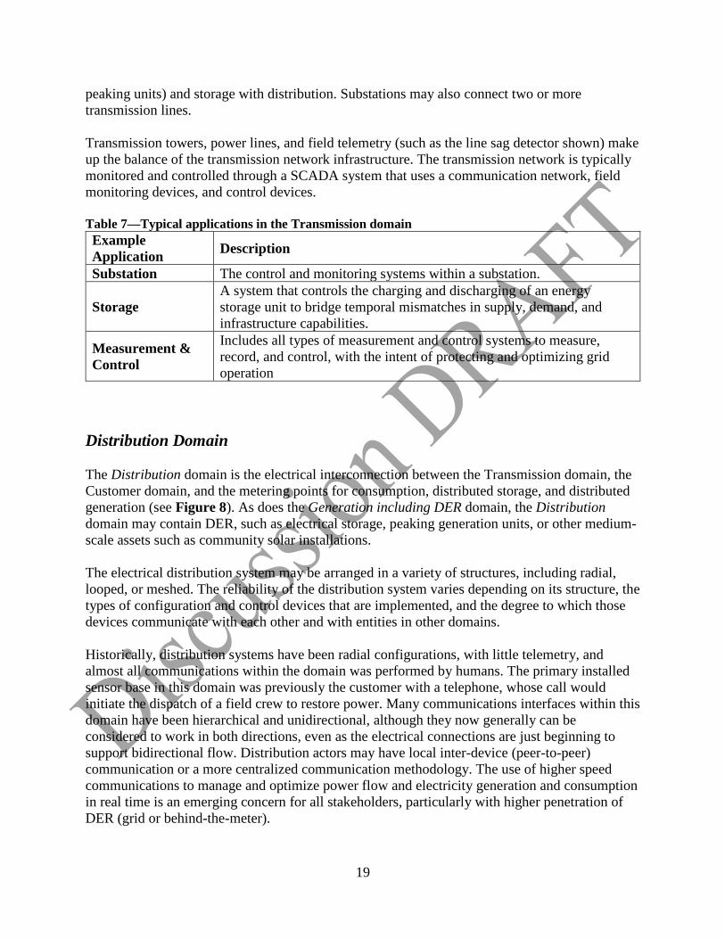
peaking units) and storage with distribution. Substations may also connect two or more transmission lines. Transmission towers, power lines, and field telemetry (such as the line sag detector shown) make up the balance of the transmission network infrastructure. The transmission network is typically monitored and controlled through a SCADA system that uses a communication network, field monitoring devices, and control devices. Table 7—Typical applications in the Transmission domain Example Application Description
Substation The control and monitoring systems within a substation.
Storage A system that controls the charging and discharging of an energy storage unit to bridge temporal mismatches in supply, demand, and infrastructure capabilities.
Measurement & Control
Includes all types of measurement and control systems to measure, record, and control, with the intent of protecting and optimizing grid operation
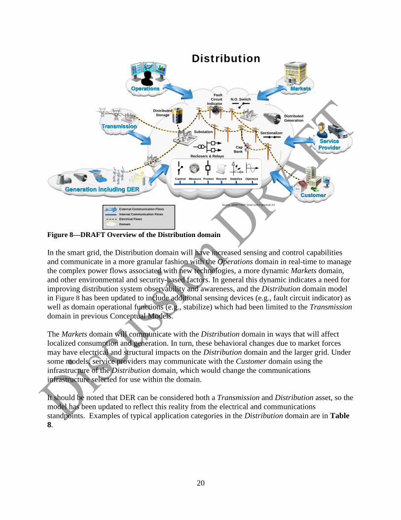
Distribution Domain The Distribution domain is the electrical interconnection between the Transmission domain, the Customer domain, and the metering points for consumption, distributed storage, and distributed generation (see Figure 8). As does the Generation including DER domain, the Distribution domain may contain DER, such as electrical storage, peaking generation units, or other medium-scale assets such as community solar installations. The electrical distribution system may be arranged in a variety of structures, including radial, looped, or meshed. The reliability of the distribution system varies depending on its structure, the types of configuration and control devices that are implemented, and the degree to which those devices communicate with each other and with entities in other domains. Historically, distribution systems have been radial configurations, with little telemetry, and almost all communications within the domain was performed by humans. The primary installed sensor base in this domain was previously the customer with a telephone, whose call would initiate the dispatch of a field crew to restore power. Many communications interfaces within this domain have been hierarchical and unidirectional, although they now generally can be considered to work in both directions, even as the electrical connections are just beginning to support bidirectional flow. Distribution actors may have local inter-device (peer-to-peer) communication or a more centralized communication methodology. The use of higher speed communications to manage and optimize power flow and electricity generation and consumption in real time is an emerging concern for all stakeholders, particularly with higher penetration of DER (grid or behind-the-meter).
20
Figure 8—DRAFT Overview of the Distribution domain In the smart grid, the Distribution domain will have increased sensing and control capabilities and communicate in a more granular fashion with the Operations domain in real-time to manage the complex power flows associated with new technologies, a more dynamic Markets domain, and other environmental and security-based factors. In general this dynamic indicates a need for improving distribution system observability and awareness, and the Distribution domain model in Figure 8 has been updated to include additional sensing devices (e.g., fault circuit indicator) as well as domain operational functions (e.g., stabilize) which had been limited to the Transmission domain in previous Conceptual Models. The Markets domain will communicate with the Distribution domain in ways that will affect localized consumption and generation. In turn, these behavioral changes due to market forces may have electrical and structural impacts on the Distribution domain and the larger grid. Under some models, service providers may communicate with the Customer domain using the infrastructure of the Distribution domain, which would change the communications infrastructure selected for use within the domain. It should be noted that DER can be considered both a Transmission and Distribution asset, so the model has been updated to reflect this reality from the electrical and communications standpoints. Examples of typical application categories in the Distribution domain are in Table 8.
Distributed Generation
Distributed Storage
Sectionalizer
Markets
Distribution
Cap Bank
N.O. Switch
Reclosers & Relays
Operations
Substation
Internal Communication FlowsElectrical FlowsDomain
External Communication FlowsSource: DRAFT NIST Smart Grid Framework 4.0
FaultCircuit
Indicator
Service Provider
Generation including DERCustomerCustomer
Transmission
Control
Measure Protect Record Stabilize Optimize
21
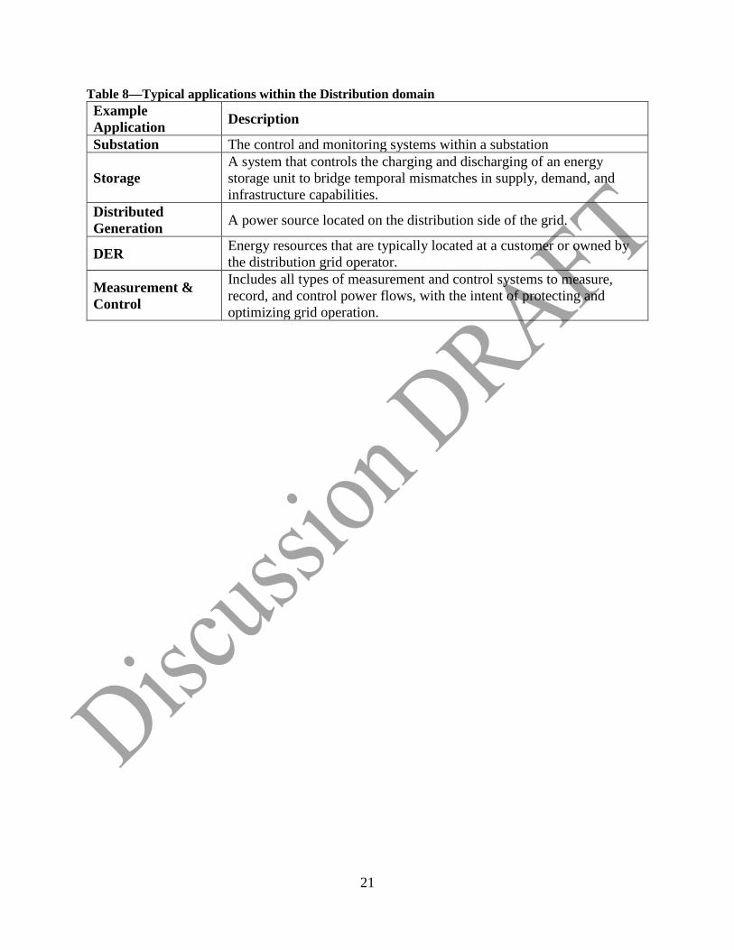
Table 8—Typical applications within the Distribution domain Example Application Description
Substation The control and monitoring systems within a substation
Storage A system that controls the charging and discharging of an energy storage unit to bridge temporal mismatches in supply, demand, and infrastructure capabilities.
Distributed Generation A power source located on the distribution side of the grid.
DER Energy resources that are typically located at a customer or owned by the distribution grid operator.
Measurement & Control
Includes all types of measurement and control systems to measure, record, and control power flows, with the intent of protecting and optimizing grid operation.