Embed Size (px)
Citation preview

SMART EMERGENCY PREEMPTION SYSTEM
EMPLOYING GPS AND FPGA
MORAALI
FACULTY OF COMPUTER SCIENCE AND
INFORMATION TECHNOLOGY UNIVERSITY OF MALAYA
KUALA LUMPUR
APRIL 2011
SMART EMERGENCY PREEMPTION SYSTEM
EMPLOYING GPS AND FPGA
MORAALI
DISSERTATION SUBMITTED IN PARTIAL FULFILMENT OF THE REQUIREMENTS FOR
THE DEGREE OF MASTER OF COMPUTER SCIENCE
FACULTY OF COMPUTER SCIENCE AND INFORMATION TECHNOLOGY
UNIVERSITY OF MALAYA KUALA LUMPUR
APRIL 2011

ABSTRACT
Emergency Vehicle Preemption (EVP) is a system that intervenes in the normal
operation of traffic control systems to grant emergency vehicles to pass through.
Conventional EVP relies on short range signals such as light, sound or radio wave
signals to interrupt the normal traffic light cycle to green. A higher response time is
expected when the blockage ahead is not preempted due to this short range signals
transmitted by the emergency vehicle. A short range signals only able to trigger one
traffic light intersection. In this thesis, Smart Emergency Vehicle Preemption system
(SEVP) is proposed to overcome these drawbacks by granting green lights to more than
one intersection within the distance or threshold set. Positioning technique and A-star
(A*) shortest path algorithm is used in the proposed system to permit the system to
control and to calibrate road traffic light systems using wireless communications
installed on emergency vehicles and traffic intersections. The system works by
installing tracking device on emergency vehicle and a modification on the traffic light
controller. For tracking purpose, FPGA embedded with Xilinx Microblaze soft
processor core and SIM 508 GPS/GSM modem is used. The FPGA will filter
unnecessary GPS data to get the current latitude and longitude of the emergency
vehicle. Then, the filtered data is transmitted via GSM modem. The current position of
the emergency vehicle and the position of emergency scene are then used by the centre
to calculate and find the shortest path route to destination. The centre will send interrupt
command to traffic controllers within the selected route and distance threshold set to
clear the cluttered traffic in front. The interrupt value is used to trigger the particular
traffic light to green and trigger the other traffic lights at the junction to be red. The
traffic light controller is then calibrated to normal mode after the emergency vehicle
passed each traffic light intersection. The ability to preempt ahead before emergency

vehicle approach traffic intersection significantly improves emergency vehicle response
time.
ii
ABSTRAK
Sistem Kenderaan Kecemasan Didahulukan (Emergency Vehicle Preemption (EVP))
adalah sebuah sistem yang mengawal operasi lalu lintas dengan memberikan laluan
kepada kenderaan kecemasan. EVP konvensional bergantung pada isyarat jarak pendek
seperti isyarat cahaya, bunyi atau isyarat gelombang radio untuk menyela kitaran lampu
lalu lintas kepada isyarat hijau. Oleh kerana isyarat dihantar kenderaan kecemasan
adalah dalam jarak yang pendek, kesesakan lalu lintas di hadapan tidak dapat dileraikan
ketika kecemasan. Isyarat jarak pendek hanya mampu mengawal lampu isyarat di satu
persimpangan lampu lalu lintas sahaja. Dalam tesis ini, Sistem Kenderaan Kecemasan
Didahulukan Pintar (Smart Emergency Vehicle Preemption (SEVP)) dicadangkan untuk
mengatasi kelemahan ini dengan memberikan isyarat hijau untuk lebih dari satu
persimpangan dalam jarak yang dihadkan. Teknik posisi dan algoritma A-star (A*)
untuk penghitungan jarak yang terpendek digunakan dalam sistem ini supaya operasi
pengawalan dan kalibrasi lampu lalu lintas dapat dilaksanakan dengan menggunakan
komunikasi wayarles yang dipasang pada kenderaan kecemasan dan pada persimpangan
lalu lintas. Sistem ini befungsi dengan cara peranti penjejakan (tracking device)
dipasang pada kenderaan kecemasan dan pengubahsuaian pada kontroler lampu lalu
lintas. Untuk menjejak, FPGA diprogramkan dengan soft processor core Xilinx
Microblaze dan SIM 508 GPS / GSM modem digunakan. FPGA akan menapis data
yang tidak perlukan oleh GPS untuk mendapatkan kedudukan garis lintang dan bujur
kenderaan kecemasan. Kemudian, data yang ditapis ini akan dihantar melalui modem
GSM. Kedudukan tempat kecemasan kemudian digunakan oleh pusat kawalan untuk
mengira dan mencari laluan jalan terpendek ke arah tempat tujuan. Pusat kawalan akan
menghantar arahan sampukan ke kontroler lalu lintas untuk memberi laluan kepada
jalan yang dipilih dalam batas jarak tertentu untuk meringankan lalu lintas di hadapan.
iii

Nilai sampukan digunakan untuk menyalakan lampu lalu lintas tertentu kepada hijau
dan menyalakan merah kepada lampu lalu lintas yang lain. Selepas kenderaan
kecemasan melewati setiap persimpangan lampu lalu lintas, kontroler lampu lalu lintas
ini akan dikalibrasikan kepada operasi asal. Kemampuan untuk mendahului kendaraan
di depan sebelum kenderaan kecemasan mendekati persimpangan lalu lintas boleh
meningkatkan waktu respon.
iv
ACKNOWLEDGEMENT
My upmost gratitude goes to my supervisors, Mr Mohd Yamani Idna Idris and Mr
Emran Bin Mohd Tamil for their endless guide in completing my thesis project. I also
thank the rest of System On Chip (SOC) group members including the lectures for their
moral support. Finally, I would like to take this opportunity to express my deepest
appreciation to my father, S.Sivalingam for supporting financially for my postgraduate
studies.
v
TABLE OF CONTENTS
ABSTRACT vi
ABSTRAK vi
ACKNOWLEDGEMENT vi
TABLE OF CONTENT vi
LIST OF FIGURES vi
LIST OF TABLES xvii
LIST OF ABBREVIATIONS xx
CHAPTER 1: INTRODUCTION
1.0 Introduction 1
1.1 Project Objective 1
1.2 Project Scope 2
1.3 Thesis Arrangement 3
CHAPTER 2: LITERATURE REVIEW
2.1 Traffic Light System 5
vi
2.2 Preemption System 11
2.2.1 Decentralized System 11
2.2.1.1 Loop based system 12
2.2.1.2 Light based system 16
2.2.1.3 Radio based system 17
2.2.1.4 Sound based system 18
2.2.2 Centralized System 18
2.2.2.1 Vehicle information System 19
2.2.2.2 Path finding system 22
2.2.2.3 Collision Avoidance System 25
2.2.2.4 Multi Agent System 26
2.3 Conclusion 29
CHAPTER 3: RESEARCH METHODOLOGY
3.0 Introduction 32
3.1 Proposed Methodology 32
3.1.1 Requirement 33
3.1.2 Design 34
3.1.3 Development 35
3.2.4 Prototyping 36
3.2. 5 Testing 37
3.2.6 Maintenance 37
3.2 Conclusion 38
vii
CHAPTER 4: PROBLEM VERIFICATION AND SYSTEM DESIGN
4.0 Introduction 39
4.1 Real Time Traffic intersection Analysis 40
4.1.1 Perceiving Intersection Characteristic 42
4.1.1.1 Intersections 42
4.1.1.1.1 “Bird Eye” View 42
4.1.1.1.2 Time/Traffic Light Table 43
4.1.1.1.3 Intersection Phasing Diagram 44
4.1.2 Identifying Intersection Problem 45
4.1.2.1 Cluttered Intersection Problem 45
4.1.2.2 Alternative Route Problem 48
4.1.2.2.1 Shortest Path Discovery Problem 48
4.1.2.2.2 Incorrect Path Selection 50
4.2 Proposed System 51
4.3 Scenario Example 54
4.4 Conclusion 57
CHAPTER 5: SYSTEM IMPLEMENTATION
5.0 Introduction 58
5.1 Emergency Vehicle Tracking (Module 1) 58
5.1.1 Module 1 Discussion 58
5.1.2 Module 1 Result 64
5.2 Central Control System (Module 2) 72
5.2.1 Module 2 Discussion 72
5.2.2 Module 2 Result 83
viii
5.2.2.1 Interface Design 84
5.2.2.1.1 Main Page 86
5.2.2.1.2 Login 87
5.2.2.1.3 Design 88
5.2.2.1.4 Mapping 95
5.2.2.1.5 Dynamic Map 96
5.2.3 Scenario Example 98
5.3 Traffic Light Controller (Module 3) 100
5.3.1 Module 3 Discussion 100
5.3.2 Module 3 Result 105
5.4 Conclusion 122
CHAPTER 6: CONCLUSION 123
REFERENCES 126
APPENDIX : PERCEIVING INTERSECTION CHARACTERISTIC 130
ix
LIST OF FIGURES
NO TITLE PAGE
Figure 2.1 Real time phase design (Abdullah, 2009) 7
Figure 2.2 Cycle time 7
Figure 2.3 Phase split 8
Figure 2.4 Phase record 8
Figure 2.5 Detector loop (Abdullah, 2009) 12
Figure 2.6 An intersection of the general configuration 13
for a preemption system using existing traffic
loops (Aaron D. Bachelder, 2006b)
Figure 2.7 Schematic block diagram of the system general 14
configuration (Aaron D. Bachelder, 2006b)
Figure 2.8 Light based system (Jeffrey F.Paniati, 2006) 16
Figure 2.9 Radio based system (Park, 2007) 17
Figure 2.10 Sound based system(Jeffrey F.Paniati, 2006) 18
x
Figure 2.11 Vehicle information system (Knockeart, 2004) 20
Figure 2.12 A simplified of RHODES operation 23
(Pitu B.Mirchandani 2004)
Figure 2.13 The CAPRI control architecture 24
(Pitu B.Mirchandani 2004)
Figure 2.14 A* path (Yanyan Chen, 2003) 25
Figure 2.15 CPN Model(Lefei Li, 2005) 28
Figure 3.1 Proposed methodologies 33
Figure 4.1 Google map of Petaling Jaya 40
Figure 4.2 Intersections at Petaling Jaya 41
Figure 4.3 Intersection A and intersection B traffic flow 42
diagram
Figure 4.4 Phases of intersection A 44
Figure 4.5 Phases of intersection B 44
xi
Figure 4.6 Intersection A and Intersection B from Figure 4.2 45
Figure 4.7 Cluttered intersection problem 45
Figure 4.8 Phase for intersection A and B 47
Figure 4.9 Phasing of intersection B 47
Figure 4.10 Blockages from Intersection B to Intersection A 48
Figure 4.11 Routes to University Hospital 49
Figure 4.12 Alternative path using the Intersection F path 50
Figure 4.13 Incorrect lane problem 51
Figure 4.14 Overview of proposed system 52
Figure 4.15 Module process implemented in SEVP 53
Figure 4.16 Smart Emergency Vehicle Preemption System 54
Figure 4.17 System Flow Chart 56
Figure 5.1 Block diagram of vehicle tracking 61
xii
Figure 5.2 Pseudocode for system module 1 63
Figure 5.3 Emergency vehicle tracking devices 64
Figure 5.4 UART ML401 connection diagram 64
Figure 5.5 UART ML401 datasheet 66
Figure 5.6 Bus Interface 67
Figure 5.7 Intellectual Property address 68
Figure 5.8 Intellectual Property ports 69
Figure 5.9 Block diagram for module 1 70
Figure 5.10 Data Input From GPS receiver 71
Figure 5.11 Filtered data 71
Figure 5.12 Central control system 72
Figure 5.13 Overall DFD 73
Figure 5.14 Specific DFD 74
xiii
Figure 5.15 Specific DFD for Process 2 75
Figure 5.16 Specific DFD for Process 76
Figure 5.17 Pseudocode for system module 2 79
Figure 5.18 A* Flow Chart 80
Figure 5.19 A* flow diagram 82
Figure 5.20 Connection of GSM and the PC 83
Figure 5.21 Project design summary 84
Figure 5.22 Main page 86
Figure 5.23 Admin page 87
Figure 5.24 Design page 88
Figure 5.25 Open recent map 89
Figure 5.26 Create a new map 89
Figure 5.27 Select Option 90
xiv
Figure 5.28 Select Main Sensor 91
Figure 5.29 Select Secondary Sensor 92
Figure 5.30 Select Congestion 93
Figure 5.31 Select a name for the map 95
Figure 5.32 Insert the location for the map 96
Figure 5.33 Test the map 97
Figure 5.34 Example Map 98
Figure 5.35 Normal path used 99
Figure 5.36 Assign the congestion level 99
Figure 5.37 Alternative path 100
Figure 5.38 Block diagram of traffic light controller 101
Figure 5.39 Traffic Light controller flow chart 102
Figure 5.40 Pseudocode for system module 3 104
xv
Figure 5.41 Traffic light controller devices 105
Figure 5.42 Expansion header wiring 106
Figure 5.43 Example of four traffic lights at one intersection 107
Figure 5.44 All the traffic lights display AMBER 108
Figure 5.45 RTL Schematics 109
Figure 5.46 RTL Schematics on Top Level 110
Figure 5.47 Details of RTL schematics on system_i 111
Figure 5.48 Block diagram for module 3 112
Figure 5.49 Clock rate division 113
Figure 5.50 ISE clock division 114
Figure 5.51 Illustration clock rate division 115
Figure 5.52 Normal traffic light flow 116
Figure 5.53 Testbench of the traffic lights 121
xvi
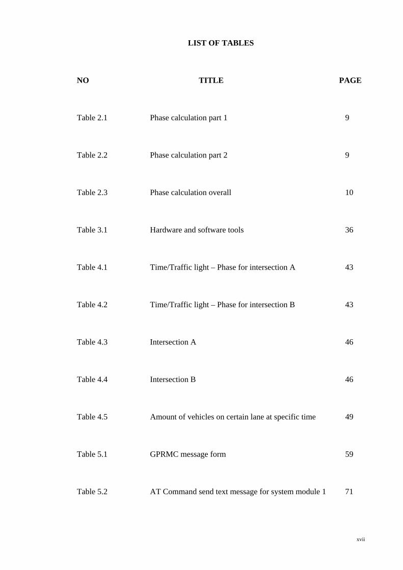
LIST OF TABLES
NO TITLE PAGE
Table 2.1 Phase calculation part 1 9
Table 2.2 Phase calculation part 2 9
Table 2.3 Phase calculation overall 10
Table 3.1 Hardware and software tools 36
Table 4.1 Time/Traffic light – Phase for intersection A 43
Table 4.2 Time/Traffic light – Phase for intersection B 43
Table 4.3 Intersection A 46
Table 4.4 Intersection B 46
Table 4.5 Amount of vehicles on certain lane at specific time 49
Table 5.1 GPRMC message form 59
Table 5.2 AT Command send text message for system module 1 71
xvii
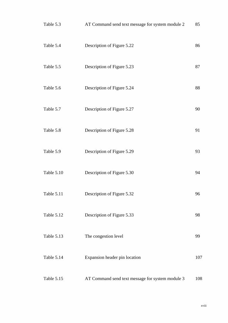
Table 5.3 AT Command send text message for system module 2 85
Table 5.4 Description of Figure 5.22 86
Table 5.5 Description of Figure 5.23 87
Table 5.6 Description of Figure 5.24 88
Table 5.7 Description of Figure 5.27 90
Table 5.8 Description of Figure 5.28 91
Table 5.9 Description of Figure 5.29 93
Table 5.10 Description of Figure 5.30 94
Table 5.11 Description of Figure 5.32 96
Table 5.12 Description of Figure 5.33 98
Table 5.13 The congestion level 99
Table 5.14 Expansion header pin location 107
Table 5.15 AT Command send text message for system module 3 108
xviii
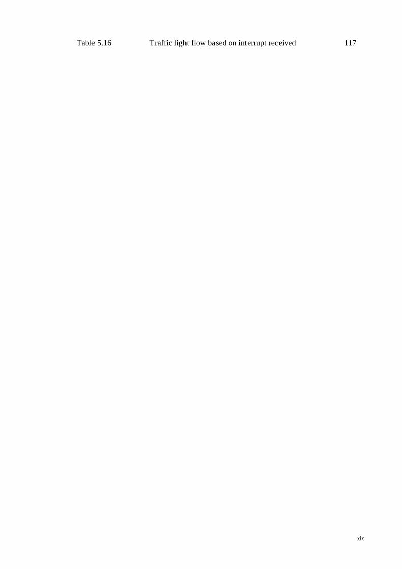
Table 5.16 Traffic light flow based on interrupt received 117
xix
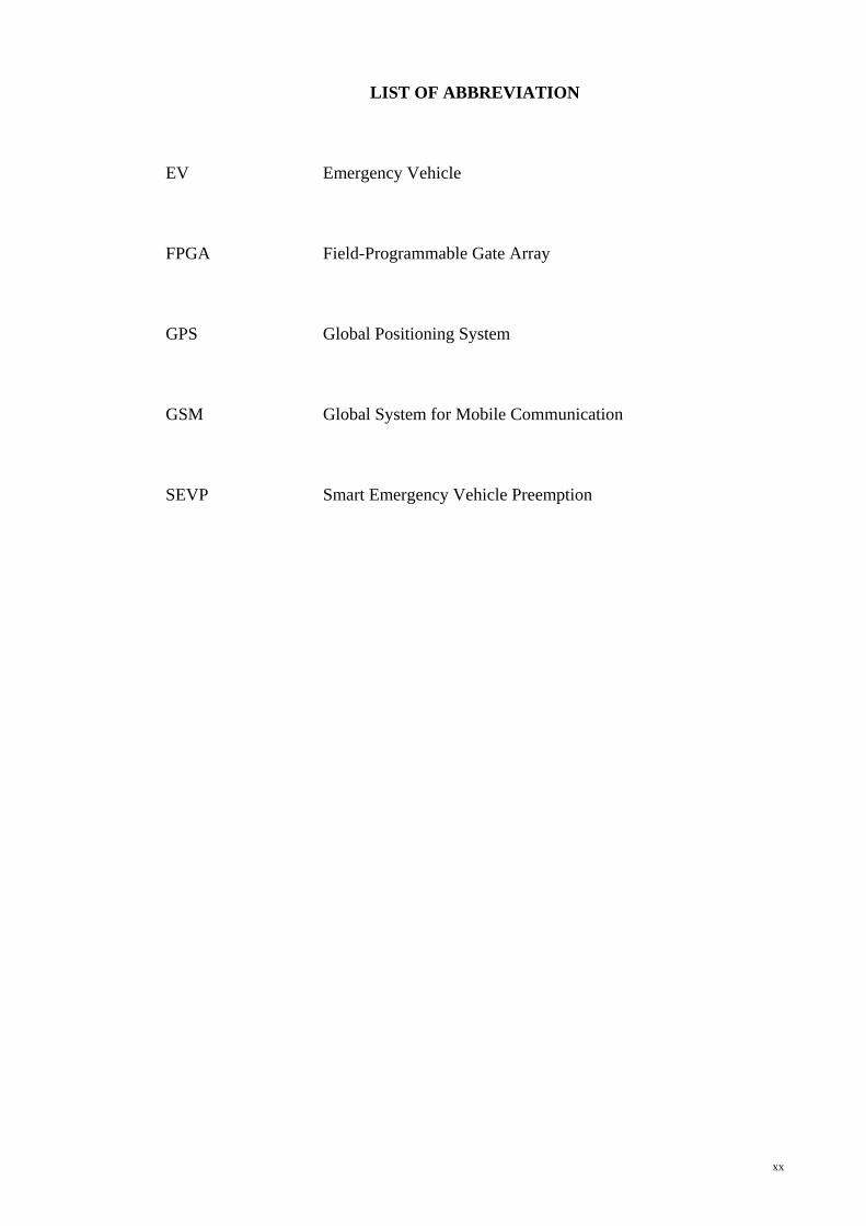
LIST OF ABBREVIATION
EV Emergency Vehicle
FPGA Field-Programmable Gate Array
GPS Global Positioning System
GSM Global System for Mobile Communication
SEVP Smart Emergency Vehicle Preemption
xx
Chapter 1 Introduction
1.0 Introduction
Road congestion, which is caused by the traffic light phase coordination, has
provided difficulties for emergency vehicle to operate in an efficient and effective
manner. As a result, the signal priority is introduced to alleviate the problem. The signal
priority is a method that grants or preempts traffic lights for certain privileged vehicles
to pass through the intersection without waiting.
Emergency vehicle preemption systems have been long initiated by developed
countries. Light, sound or radio preemption systems are examples of decentralized
category. This kind of preemption only operates when it perceives any signal
transmitted by the vehicle. However, this preemption does not perform effectively if the
vehicle is caught in a heavy traffic jam. It is because it unable to trigger for preemption
because of its long distance from the system receiver. Therefore, a centralized type of
preemption is introduced. Centralized type will preempt traffic lights at each
intersection by tracking the vehicle by applying Global Positioning System (GPS) tools.
Inability to detect vehicle in a tunnel or in a flyover are some of the negative aspects of
centralized preemptions system.
The purpose of thesis is to identify the drawbacks of the decentralized as well as
the centralized in order to design an excellent prototype that can alleviate the classified
drawbacks of preemption system for emergency vehicle.
1.1 Project Objective
The project’s main objectives can be divided into four categories, which are:-
1
1. To design Smart Emergency Vehicle Preemption System (SEVP) based on the
existing emergency vehicle preemption drawbacks.
2. To develop a prototype of the designed SEVP.
1.2 Project Scope
The project scope is based on two modules, which are the software and the
hardware section. The software section is focus on the central system. This central
provides only one emergency vehicle at a time an appropriate route to the destination
that consumes less congestion. The administrator has the only privilege to insert and
delete road congestion based on the CCTV observation. The map used in the system is
only small simulated map that has a good scalability.
The hardware section operates in two ways autonomously for the central.
Firstly, it acts solely as a tracking device embedded in the emergency vehicle. With the
help of GPS, it will able to detect the current location of the vehicle. The location
variables will be sent to the central system to calculate the shortest path via Global
System for Mobile Communication (GSM).The second method is by triggering the
traffic lights based on the input receive from the central system through GSM. This
hardware is installed in the traffic light controller. It is very important to ensure proper
traffic lights are being triggered. Therefore a small lab scale traffic light intersection is
designed to provide a vivid of understanding.
2
1.3 Thesis Arrangement
Chapter 1 Introduction
An overall background of the thesis, including problem statement, project
objective and research scope are explicated. The thesis organization for this research is
discussed.
Chapter 2 Literature Review
This chapter provides the drawbacks of conventional and current system. In the
discussion section of this chapter explain the reasons for the need to develop a system
that can alleviate the previous drawbacks.
Chapter 3 Methodology
The procedure steps taken based on a standard framework where various
hardware and software apparatus is applied for designing and testing the system is
clarified in detail.
Chapter 4 Problem Verification and System Design
The manageability of flow for traffic light signal at each intersection during
urgent situation in Malaysia is elucidated. It specifies the constraint which affects the
overall traffic light synchronization flow. The system’s idea for a system design is
3

explained in form of flow charts, diagrams as well as pseudo codes in this chapter.
Chapter 5 System Implementation
The project’s result based on the techniques elucidated in Chapter 5 is shown
evidently by providing system snapshot.
Chapter 6 Conclusion
The success to satisfy the system project’s objectives, which were discussed in
the Introduction Chapter, is clarified in brief. In addition, extra ideas for future research
improvement and enhancement are provided.
4
Chapter 2 Literature Review
Preemption system and traffic system shares common background and are
closely related to each other. To understand preemption system, overall architecture of
traffic system flow should be studied. For that reason, the beginning of this chapter will
present how traffic system works. Following that, various preemption systems including
the conventional and current systems will be reviewed and discussed.
2.1 Traffic Light System
Traffic signals have long been used to regulate the flow of traffic (Schwartz,
2008 ). Traffic lights at each intersection can alter their signal sequence based on
specific phase or stages with this timing mechanism. City intersections are often very
complex in their physical layout and often several intersections are mutually interacting
as heavy traffic flows. Therefore, the traffic light may have many different
configurations (Yang Chen, 2006). In addition, the pattern of traffic flow often varies
during the day.
There are two types of mode operation. The timing for the traffic light is function on
two mechanisms which are:-
• Fixed Time Mode
- It is permanent set by the authority based on the jurisdiction’s Multiplan.
• Vehicle Actuation Mode
- It is automatically function based on the dynamic input of the loop detector.
5
A signal group is a set of RED, AMBER and GEEN light display. This display is
relied on the vehicle direction path movement. There are three types of movements:-
• Through moving vehicles
• Right Turning vehicles
• Left Turning vehicles
Movements are usually group together to permit maximum efficiency of operation a
well as ensuring that the safety of the motorist is not compromised. In short, the
combination movement groups operating together are called as Phase. Phase is also
called as stage. Phase is the period or duration of time given to one set of non-
conflicting traffic streams. It can consist of one or more signal groups. The number of
phases should be kept to a minimum to maximize the use of time. This is to provide
flexibility for Vehicle Actuation Mode. As many movement should be allowed to run in
every phase. This is to increase the time optimization for particular lanes that are not
conflicting. A phase should have preferably consisted of non-conflicting movements.
This is done to avoid undesirable mishaps.
6
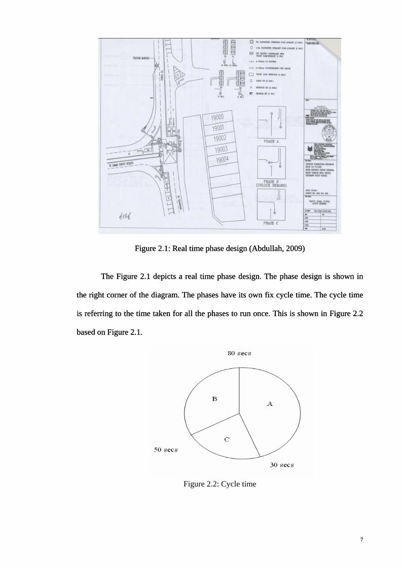
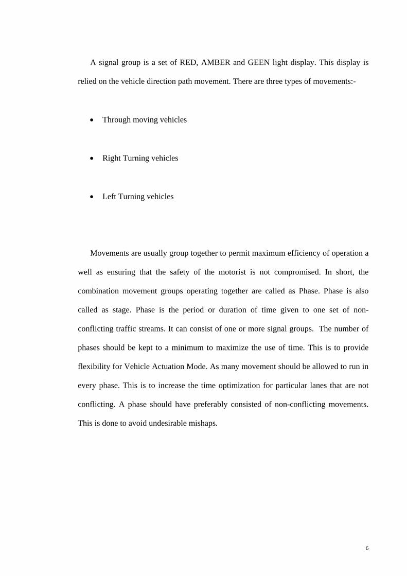
Figure 2.1: Real time phase design (Abdullah, 2009) Figure 2.1: Real time phase design (Abdullah, 2009)
The Figure 2.1 depicts a real time phase design. The phase design is shown in
the right corner of the diagram. The phases have its own fix cycle time. The cycle time
is referring to the time taken for all the phases to run once. This is shown in Figure 2.2
based on Figure 2.1.
The Figure 2.1 depicts a real time phase design. The phase design is shown in
the right corner of the diagram. The phases have its own fix cycle time. The cycle time
is referring to the time taken for all the phases to run once. This is shown in Figure 2.2
based on Figure 2.1.
Figure 2.2: Cycle time
7 7
A B and C represent Phase A, Phase B and Phase C respectively. Specific timing
is assigned to each phase based on the timing calculated by the engineers to ensure there
is no any further congestion for each phase. The specific timing of the cycle time can be
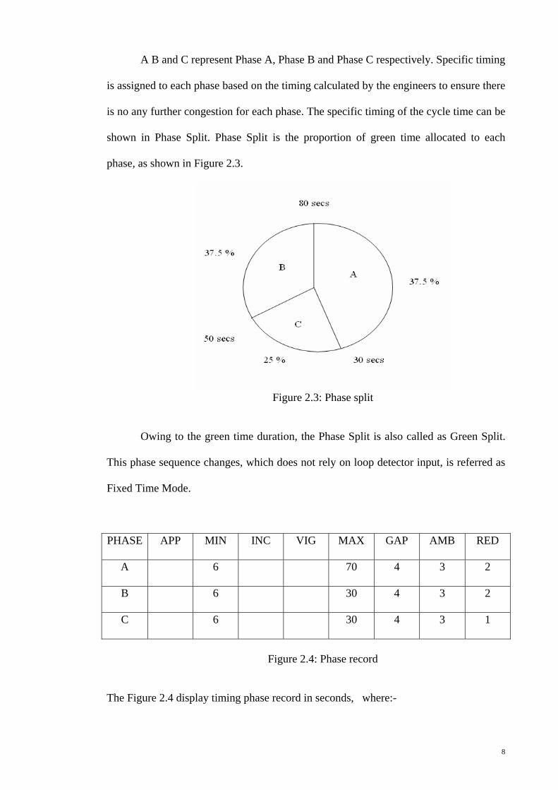
shown in Phase Split. Phase Split is the proportion of green time allocated to each
phase, as shown in Figure 2.3.
Figure 2.3: Phase split
Owing to the green time duration, the Phase Split is also called as Green Split.
This phase sequence changes, which does not rely on loop detector input, is referred as
Fixed Time Mode.
PHASE APP MIN INC VIG MAX GAP AMB RED
A 6 70 4 3 2
B 6 30 4 3 2
C 6 30 4 3 1
Figure 2.4: Phase record
The Figure 2.4 display timing phase record in seconds, where:-
8
• GREEN light timing actuation is based on MIN,MAX and GAP
• AMBER light timing actuation is based on AMB
• RED light timing actuation is based on RED
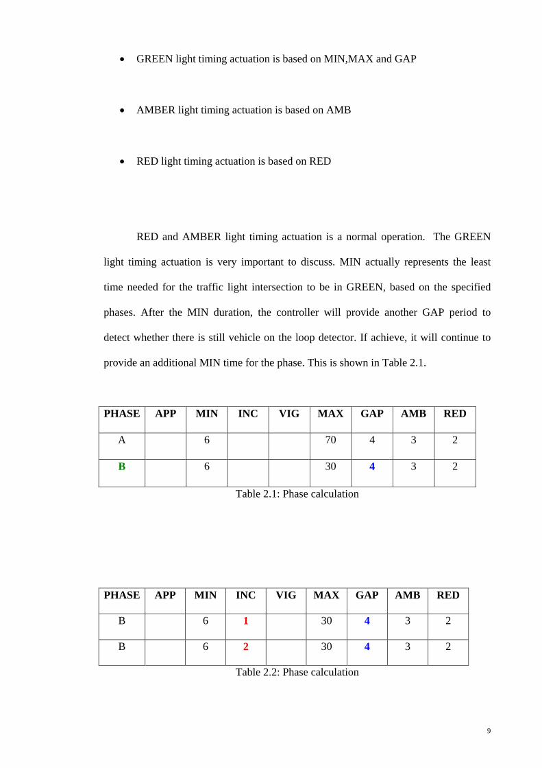
RED and AMBER light timing actuation is a normal operation. The GREEN
light timing actuation is very important to discuss. MIN actually represents the least
time needed for the traffic light intersection to be in GREEN, based on the specified
phases. After the MIN duration, the controller will provide another GAP period to
detect whether there is still vehicle on the loop detector. If achieve, it will continue to
provide an additional MIN time for the phase. This is shown in Table 2.1.
PHASE APP MIN INC VIG MAX GAP AMB RED
A 6 70 4 3 2
B 6 30 4 3 2
Table 2.1: Phase calculation
PHASE APP MIN INC VIG MAX GAP AMB RED
B 6 1 30 4 3 2
B 6 2 30 4 3 2
Table 2.2: Phase calculation
9
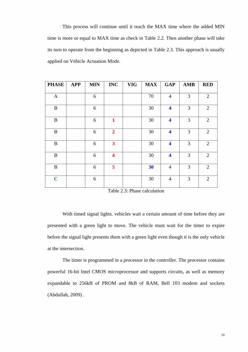
This process will continue until it reach the MAX time where the added MIN
time is more or equal to MAX time as check in Table 2.2. Then another phase will take
its turn to operate from the beginning as depicted in Table 2.3. This approach is usually
applied on Vehicle Actuation Mode.
PHASE APP MIN INC VIG MAX GAP AMB RED
A 6 70 4 3 2
B 6 30 4 3 2
B 6 1 30 4 3 2
B 6 2 30 4 3 2
B 6 3 30 4 3 2
B 6 4 30 4 3 2
B 6 5 30 4 3 2
C 6 30 4 3 2
Table 2.3: Phase calculation
With timed signal lights, vehicles wait a certain amount of time before they are
presented with a green light to move. The vehicle must wait for the timer to expire
before the signal light presents them with a green light even though it is the only vehicle
at the intersection.
The timer is programmed in a processor in the controller. The processor contains
powerful 16-bit Intel CMOS microprocessor and supports circuits, as well as memory
expandable to 256kB of PROM and 8kB of RAM, Bell 103 modem and sockets
(Abdullah, 2009) .
10
2.2 Preemption System
Although standard traffic lights discussed in the previous section have improved
the control, they cannot respond effectively for emergency vehicles to cross or enter the
intersection immediately. Therefore, emergency and other vehicles may be delayed
behind traffic while waiting for the light to change (Apitz and Dyer, 2001 ).
To make the matter worse, latest vehicles have been designed to be “air-type,
noise-reduction” which have limited driver’s awareness sudden changes of the traffic
light phase. Eventually, the emergency vehicle will not be given way to maneuver.
It has been widely accepted that, particularly in high density traffic area, there is
a vital need for such preemption control systems for emergency vehicles (Apitz and
Dyer, 2001 ). The main function of preemption control systems are providing an
unimpeded path to pass through an intersection and avoiding collision occur from the
approaching direction.
In order to explain the preemption system easily, the system is classified in two
categories, which is decentralized and centralized system.
2.2.1 Decentralized System
A decentralized system normally compromises transmitter, detector, processing
circuit, phase selector processor and traffic light controller (Schwartz, 2008b).
Emergency signal broadcasted from the vehicle based transmitter will be obtained by
the intersection receiver. Later the signal will be linked to a control circuitry where new
phase of traffic light sequence is actuated to permit the vehicle to pass through safely
the intersection. The new phase preempts the existing status of the traffic lights in
response to the approach of an emergency vehicle to an intersection under an
11
emergency condition (Poursartip, 2003). The detector systems are loop based system,
light based system, sound based system and radio wave system.
2.2.1.1 Loop based system
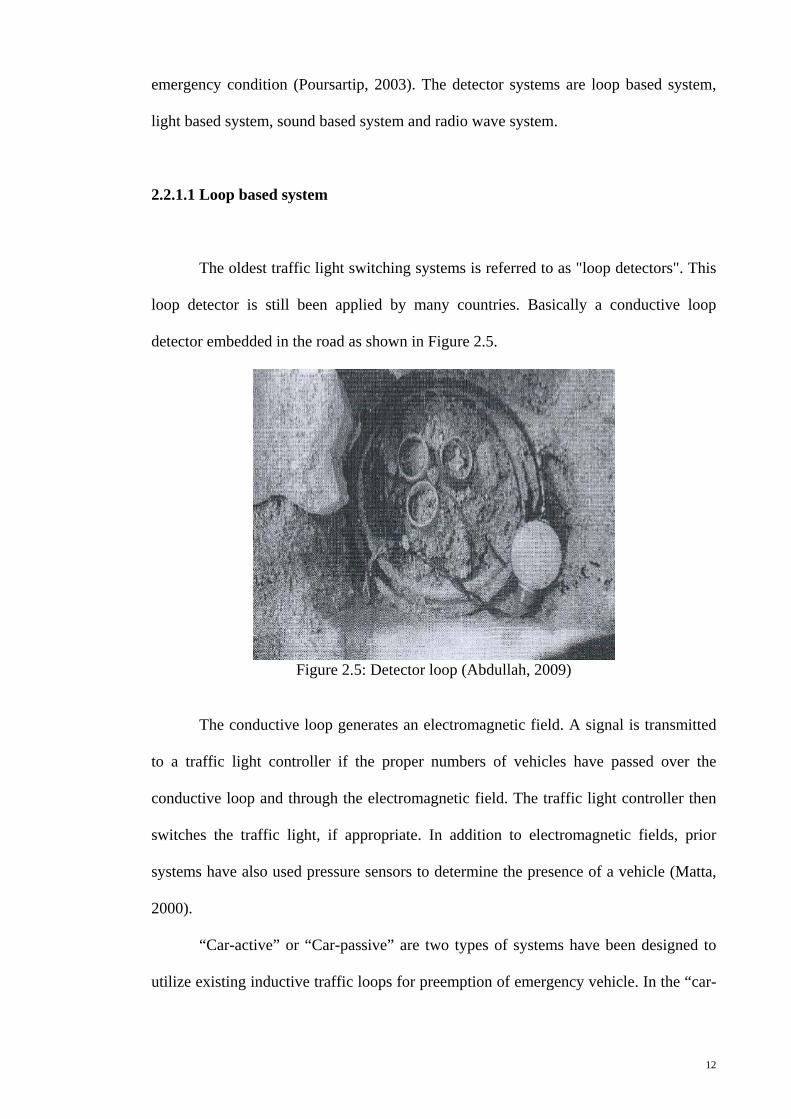
The oldest traffic light switching systems is referred to as "loop detectors". This
loop detector is still been applied by many countries. Basically a conductive loop
detector embedded in the road as shown in Figure 2.5.
Figure 2.5: Detector loop (Abdullah, 2009)
The conductive loop generates an electromagnetic field. A signal is transmitted
to a traffic light controller if the proper numbers of vehicles have passed over the
conductive loop and through the electromagnetic field. The traffic light controller then
switches the traffic light, if appropriate. In addition to electromagnetic fields, prior
systems have also used pressure sensors to determine the presence of a vehicle (Matta,
2000).
“Car-active” or “Car-passive” are two types of systems have been designed to
utilize existing inductive traffic loops for preemption of emergency vehicle. In the “car-
12
active” system, an emergency vehicle sent its position information to the traffic loop
control box when it is detected by the existing inductive traffic loop for preemption.
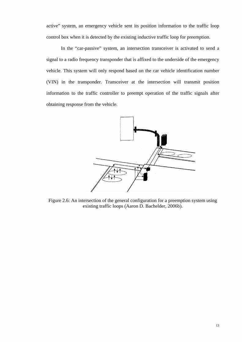
In the “car-passive” system, an intersection transceiver is activated to send a
signal to a radio frequency transponder that is affixed to the underside of the emergency
vehicle. This system will only respond based on the car vehicle identification number
(VIN) in the transponder. Transceiver at the intersection will transmit position
information to the traffic controller to preempt operation of the traffic signals after
obtaining response from the vehicle.
Figure 2.6: An intersection of the general configuration for a preemption system using existing traffic loops (Aaron D. Bachelder, 2006b).
13
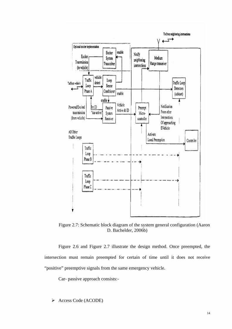
Figure 2.7: Schematic block diagram of the system general configuration (Aaron
D. Bachelder, 2006b)
Figure 2.6 and Figure 2.7 illustrate the design method. Once preempted, the
intersection must remain preempted for certain of time until it does not receive
“positive” preemptive signals from the same emergency vehicle.
Car- passive approach consists:-
Access Code (ACODE)
14
Direction Code (DCODE)
The intersection transmitter/receiver monitors the intersection by sending the
A/DCODE signal continuously in the approach directions relative to the intersection. If
an emergency vehicle approaching the intersection receives the A/DCODE, the
emergency vehicle receives the signal and sends back to the intersection with vehicle
identification code ("VID") (Brown et al., 1992 ). If the authorization for the vehicle is
verified to be true, the intersection will be given a valid preemption.
Independent control of the traffic light controlled intersections has been made
possible through the introduction of embedded processor based traffic light controllers.
Traffic signals are typically determined by an intersection controller (Bonner and
Faerber, 1980 ). A majority of the signal controlled intersections now operate on a
stand-alone basis, receiving inputs from external sensors (Bentrott et al., 1999 ).
Physical loop detectors are considered primitive for conventional traffic light switching
systems. In addition, there are many problems regarding the loop detector, which is
permanently embedded in the roadway which cannot be quickly or easily moved or
modified.
15

2.2.1.2 Light based system
Figure 2.8: Light based system (Jeffrey F.Paniati, 2006)
Light based system uses the visible light spectrum as the preemptive control
between the emergency vehicle and the intersection (Bentrott et al., 1999 ). This system
are limited by the line of sight up to almost 1,800 feet between the vehicle and the
intersection control unit (Gerald W. Pfleging, 2005) .
A flashing light beam is mounted on the emergency vehicle. As an emergency
vehicle approaches an intersection, the emergency vehicle emits a preemption request
comprised of a stream of light pulses occurring at a predetermined repetition rate as
shown in Figure 2.8.
The intersection will receive the emergency signal which is a stream of light
pulses via a detector channel which is called as photocell (Hall et al., 1996). The
microprocessor circuitry applies a windowing algorithm to validate that pulses of light
were transmitted from a valid optical traffic preemption system emitter. Hamer
(Schwartz, 2008 ) proposed variable data to be transmitted in a stream of light pulses by
segregating data pulses and priority pulses. These priority pulses are able to identify
vehicle for security purpose.
16
After receiving, the main controller of the traffic lights will actuate the phase
selector which will trigger the traffic light signals for the emergency vehicle to pass
through(Hall et al., 1996).
Munkberg (Zhang and Mclaren, 2007 ) proposed an idea where preemption
system can be based on different priority level where the signal controller can
discriminate between requests of differing priority and give precedence to the higher
priority signal. Repetition rate light pulses are indicative of its priority level. This
method preempts an intersection in favor of the higher-priority vehicle when two
vehicles having different priorities approach the intersection simultaneously from
different directions
2.2.1.3 Radio based system
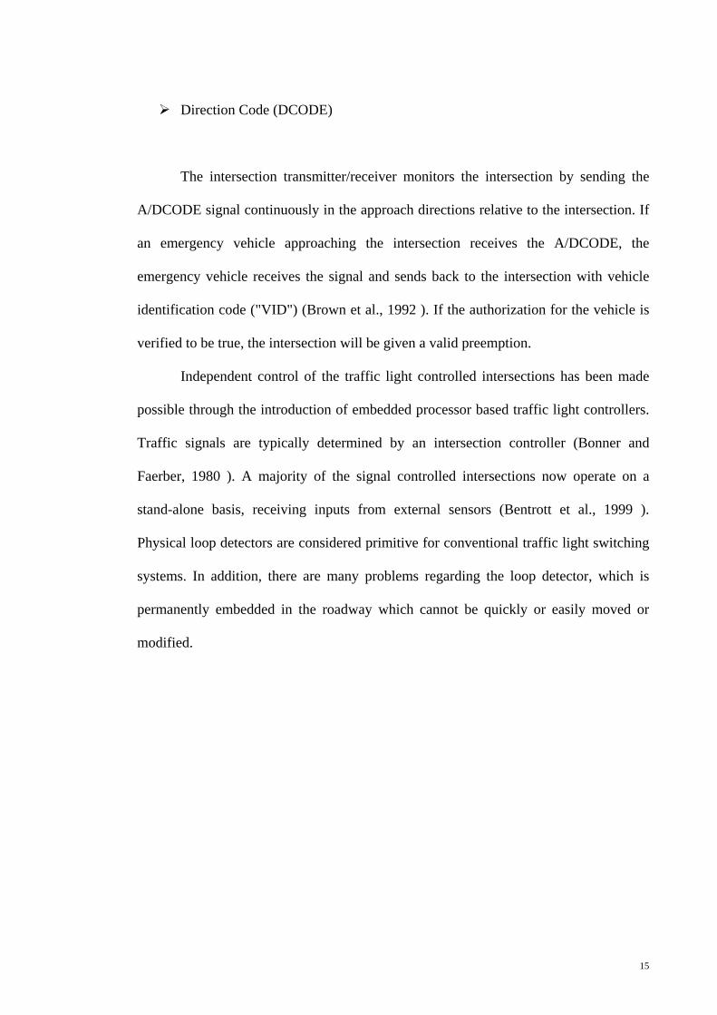
Figure 2.9: Radio based system (Park, 2007)
A system was proposed by J. C. Lesher where the system can prevent
interference of two emergency vehicles simultaneously attempting to control the traffic
lights (Morgan and Cross, 1990 ). The emergency vehicle broadcasts an encoded
microwave signal to preempt traffic lights.
A microwave antenna is mounted at an intersection. A transponder at
intersection receiver is used to confirm the direction of the transmitted signal of the
17
vehicle(Zhang and Mclaren, 2007 ) as shown in Figure 2.9. When the signal is received
by the antenna, it will decode the signal with the aid of the traffic light controller to
decide the phase to trigger the traffic lights.
2.2.1.4 Sound based system
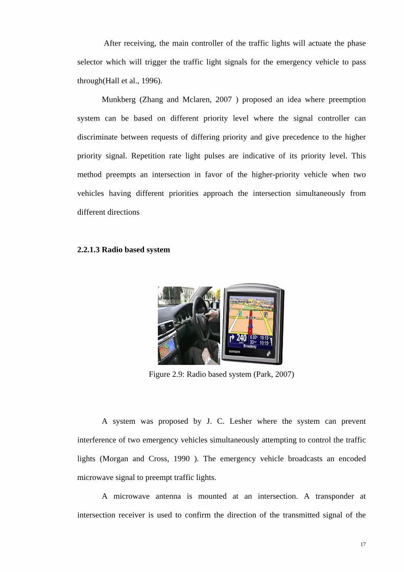
Figure 2.10: Sound based system(Jeffrey F.Paniati, 2006)
Sound signal or acoustical signal is used interchangeably in this section. The
siren emitted by the emergency vehicle will be received at the intersection as shown in
Figure 2.10. The intersection has a sonic receiver which is tuned to a certain sound
frequencies (Morgan and Cross, 1990 ).The sonic receiver will determine the direction
of approach to initiate the proper traffic light preemption sequence (Schwartz, 2008c).
2.2.2 Centralized System
Centralized system uses real time monitoring to track the position of emergency vehicle
and estimate time of arrival of the emergency vehicle at the intersection. The system
provides real-time feedback, monitoring and logging based on the intersection
18
preemption data. Accuracy of map-matching that able to determine the precise
emergency vehicle location can provides huge advantage on the efficiency of precise
phase’s changes process. This feature allows the intersection to alert the motorist and
pedestrians earlier to ensure safety. The timing of the pedestrian and clearing phases at
an intersection is incorporated into calculations to start preemption at any given
intersection (Aaron D. Bachelder, 2008). In addition, the system can able to calculate
shortest path and provide the shortest route to the emergency vehicle to employ. Vehicle
information system explains the mechanism of vehicle tracking which helps preemption
for intersection traffic lights. Instead of tracking, path finding system explicates the
obtainable appropriate pathways based on navigation abilities. The approach used to
refrain from accident with other vehicles from opposite direction during preemption is
discussed in collision avoidance system. Multi agent system provides a view on how
preemption priority is given to more than emergency vehicle.
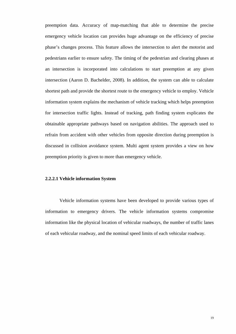
2.2.2.1 Vehicle information System
Vehicle information systems have been developed to provide various types of
information to emergency drivers. The vehicle information systems compromise
information like the physical location of vehicular roadways, the number of traffic lanes
of each vehicular roadway, and the nominal speed limits of each vehicular roadway.
19
Figure 2.11: Vehicle information system (Knockeart, 2004)
Basically, an on-board map is installed in the vehicle to ease the driver to plan a
route from a starting point to a destination as shown in Figure 2.11. The destination is
specified by inputting the desired location destination or selecting an option listed, like
gas stations. Once the driver determines the destination, the system will provide a
planned route which consumes less travel time (Ames, 2006).This planned is presented
to the driver in two ways. The first way is by providing a sequence of discrete
instructions is given to the driver. This is to ensure the whether driver is prepared to
react at each intersection. For instance, alerting the driver to turn left when reach a
particular junction. The second approach is by using a map to displays the vehicle’s
location dynamically. The driver uses the map to decide when and where to turn in
order to follow the planned route
An emergency vehicle is equipped with a GPS receiver. The GPS receiver is
used to determine the emergency vehicle's location and heading (Aaron D. Bachelder,
2006a). Data based on the emergency vehicle's location and heading are transmitted
20
from the emergency vehicle to intersection controllers. The intersection controller uses
the data indicating the emergency vehicle position and heading to determine whether
the emergency vehicle is on any road that might lead to the intersection. If the
emergency vehicle is on any road heading toward an intersection, the intersection
controller actuates the traffic signals at the intersection to give the emergency vehicle
the right-of-way. GPS is used to estimate the position of a preempting vehicle. The
estimation accuracy is improved using map matching techniques (Aaron D. Bachelder,
2006b)
approach the intersection. The range of detection is about
2500 fe
llers. It is very important to
determine the appropriate phase for the emergency vehicle.
.
Automated vehicle location (AVL) and control (AVLC) system that
communicates with either a traffic signal controller at the intersection or with a control
central or combination of both (Poursartip, 2003 ). This system can be considered as
multi-million dollar satellite-based GPS systems. This system applies “entry” criteria
and “exit” criteria. If the emergency vehicle is a suitable distance to the intersection,
“entry” criteria” will be applied. After the emergency vehicle passed the intersection,
“exit” criteria will be applied (Knockeart, 2004). This system can perceive the location
of emergency vehicles as they
et (Poursartip, 2003) .
All the traffic lights are controlled from a central console. Usually the central is
located in any government building like the police radio room. Operator of the central
will always have two-way communication with the emergency drivers. Based on the
GPS mapping, the operator will guide the emergency driver to use certain path to reach
the destination faster. When the emergency vehicle reaches an intersection, the operator
actuates a certain traffic lights phase by granting green light for the emergency vehicle
to pass (Knockeart, 2004). The judgment activates a certain traffic lights phase is based
on received diagnostic information from intersection contro
21
Instead of the operator interference, there is another approach where operator
function is completely ignored. The emergency vehicle is equipped with devices, like
antenna, to determine the position of the emergency vehicle. The emergency vehicle has
to transmit GPS position data periodically to the control central. Then, the control
central will calculate the speed and estimated arrival time to determine if traffic signal
preemption is needed at the intersection. If confirm, the control central will send
preemption request, based on the vehicle priority status, to the traffic signal controller
(Bonner and Faerber, 1980 ).
When GPS signal is obstructed, dead reckoning techniques can be used to
alleviate the problem (Aaron D. Bachelder, 2006b) . This technique able to determine
the vehicle position based on the previous location and other relevant information like
speed and heading direction. Emergency vehicle is installed on-board-dead reckoning
system. When the emergency vehicle passes a traffic loop, it receives intersection ID to
be looked up in latitude/longitude location database estimate future positions. Primary
location information with a dead reckoning system provides location information when
poor reception prevents the GPS system from functioning.
2.2.2.2 Path finding system
Finding reliable path is not an easy task as lack of dynamic traffic data can be
acquired for the entire network especially during disaster. Therefore, preplanning best
route is very crucial for emergency vehicles to reduce rescue operation delay.
There are many varieties of method used to provide shortest path for emergency
vehicle. Mona (Mona E.Rizvi) proposed a Vehicular Ad Hoc Networks (VANETs)
based approach that operate with emergency vehicle preemption system in order to
22
provide suitable route information for emergency service vehicle with the intention of
reducing traffic chaos during evacuation and non-evacuation conditions.
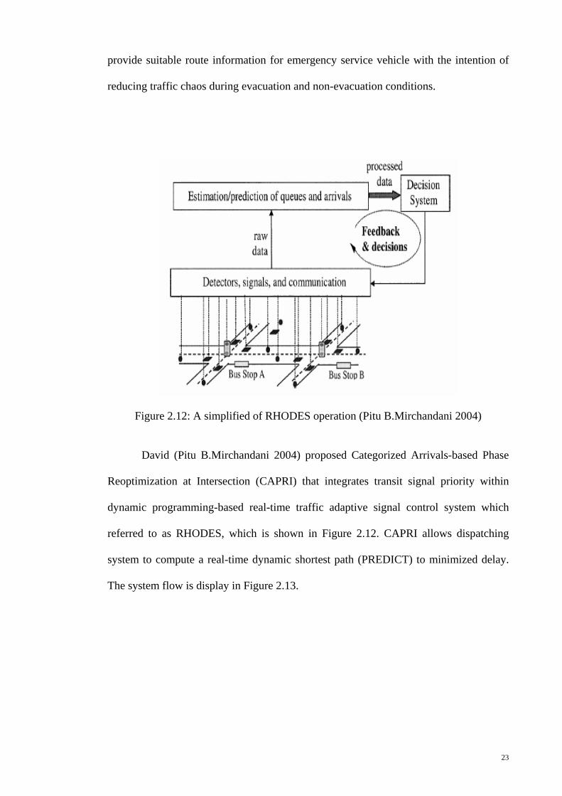
Figure 2.12: A simplified of RHODES operation (Pitu B.Mirchandani 2004)
David (Pitu B.Mirchandani 2004) proposed Categorized Arrivals-based Phase
Reoptimization at Intersection (CAPRI) that integrates transit signal priority within
dynamic programming-based real-time traffic adaptive signal control system which
referred to as RHODES, which is shown in Figure 2.12. CAPRI allows dispatching
system to compute a real-time dynamic shortest path (PREDICT) to minimized delay.
The system flow is display in Figure 2.13.
23
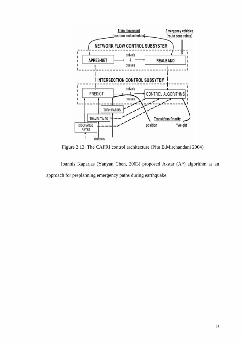
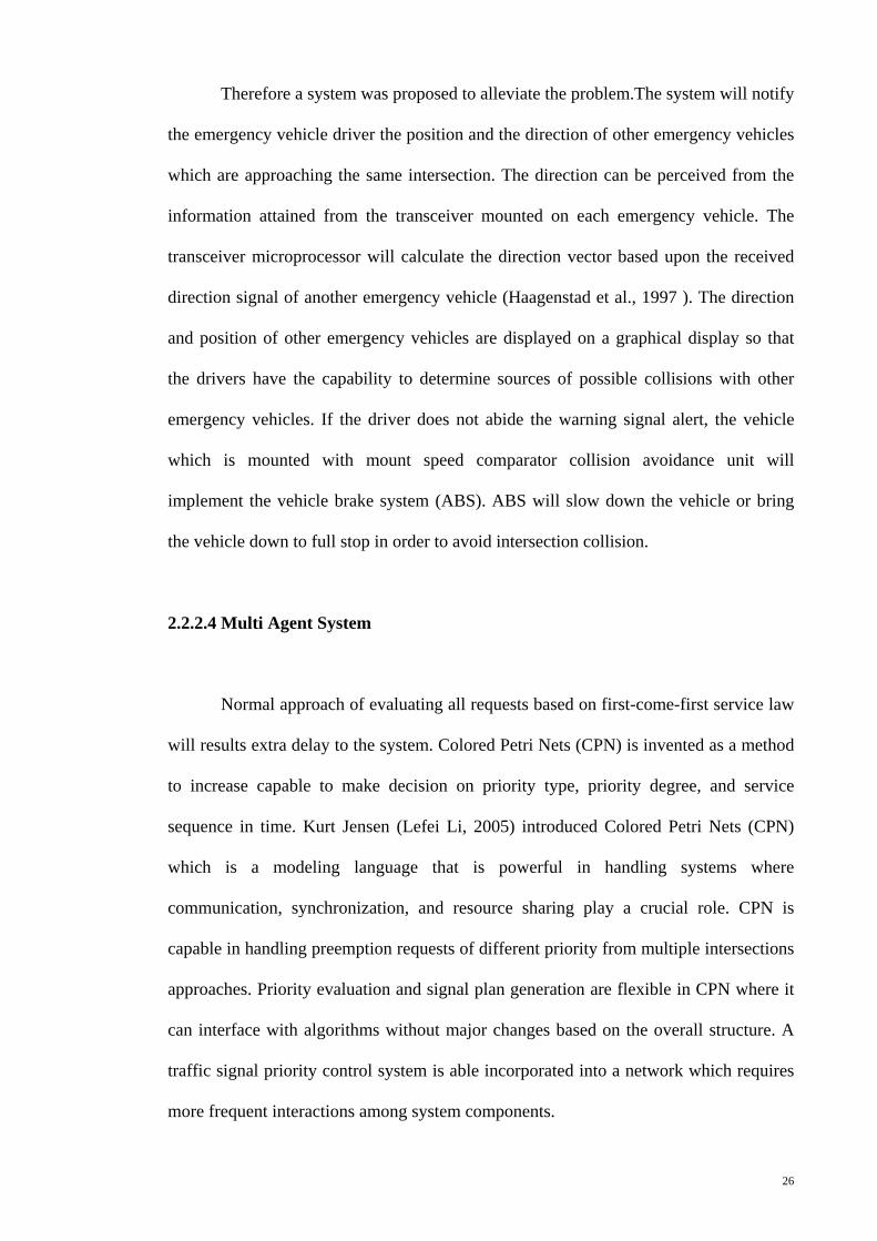
Figure 2.13: The CAPRI control architecture (Pitu B.Mirchandani 2004)
Ioannis Kaparias (Yanyan Chen, 2003) proposed A-star (A*) algorithm as an
approach for preplanning emergency paths during earthquake.
24
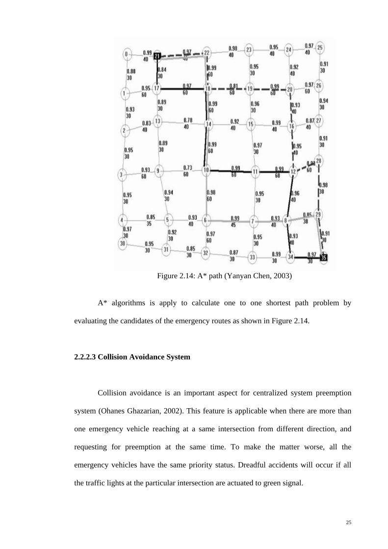
Figure 2.14: A* path (Yanyan Chen, 2003)
A* algorithms is apply to calculate one to one shortest path problem by
evaluating the candidates of the emergency routes as shown in Figure 2.14.
2.2.2.3 Collision Avoidance System
Collision avoidance is an important aspect for centralized system preemption
system (Ohanes Ghazarian, 2002). This feature is applicable when there are more than
one emergency vehicle reaching at a same intersection from different direction, and
requesting for preemption at the same time. To make the matter worse, all the
emergency vehicles have the same priority status. Dreadful accidents will occur if all
the traffic lights at the particular intersection are actuated to green signal.
25
Therefore a system was proposed to alleviate the problem.The system will notify
the emergency vehicle driver the position and the direction of other emergency vehicles
which are approaching the same intersection. The direction can be perceived from the
information attained from the transceiver mounted on each emergency vehicle. The
transceiver microprocessor will calculate the direction vector based upon the received
direction signal of another emergency vehicle (Haagenstad et al., 1997 ). The direction
and position of other emergency vehicles are displayed on a graphical display so that
the drivers have the capability to determine sources of possible collisions with other
emergency vehicles. If the driver does not abide the warning signal alert, the vehicle
which is mounted with mount speed comparator collision avoidance unit will
implement the vehicle brake system (ABS). ABS will slow down the vehicle or bring
the vehicle down to full stop in order to avoid intersection collision.
2.2.2.4 Multi Agent System
Normal approach of evaluating all requests based on first-come-first service law
will results extra delay to the system. Colored Petri Nets (CPN) is invented as a method
to increase capable to make decision on priority type, priority degree, and service
sequence in time. Kurt Jensen (Lefei Li, 2005) introduced Colored Petri Nets (CPN)
which is a modeling language that is powerful in handling systems where
communication, synchronization, and resource sharing play a crucial role. CPN is
capable in handling preemption requests of different priority from multiple intersections
approaches. Priority evaluation and signal plan generation are flexible in CPN where it
can interface with algorithms without major changes based on the overall structure. A
traffic signal priority control system is able incorporated into a network which requires
more frequent interactions among system components.
26
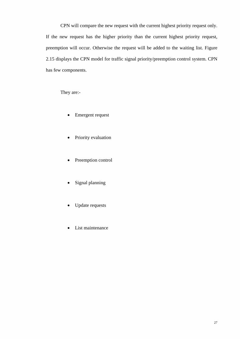
CPN will compare the new request with the current highest priority request only.
If the new request has the higher priority than the current highest priority request,
preemption will occur. Otherwise the request will be added to the waiting list. Figure
2.15 displays the CPN model for traffic signal priority/preemption control system. CPN
has few components.
They are:-
• Emergent request
• Priority evaluation
• Preemption control
• Signal planning
• Update requests
• List maintenance
27
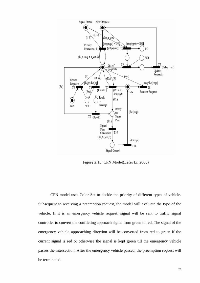
Figure 2.15: CPN Model(Lefei Li, 2005)
CPN model uses Color Set to decide the priority of different types of vehicle.
Subsequent to receiving a preemption request, the model will evaluate the type of the
vehicle. If it is an emergency vehicle request, signal will be sent to traffic signal
controller to convert the conflicting approach signal from green to red. The signal of the
emergency vehicle approaching direction will be converted from red to green if the
current signal is red or otherwise the signal is kept green till the emergency vehicle
passes the intersection. After the emergency vehicle passed, the preemption request will
be terminated.
28
On the whole, traffic lights are needed to control the flow of vehicles at each
intersection. There is a new system introduced where the concept of traffic light can be
ignored. Vehicles, including emergency vehicle and non-emergency vehicle, are
controlled by a computer and the intersections are equipped with wireless
communication system. This communication system corresponds with the oncoming
vehicles to permit passage for emergency vehicles. Every vehicle is equipped with
autonomous features making autonomous vehicle navigation possible. The basic idea is
to instruct or train the vehicles to be independent without relying on the centralized
control for passage aid. The concept of vehicles being autonomous agents is basically
based on Multi Agent Systems (MAS) theory (S. Saroiu, 2002). This MAS theory is a
subfield of artificial intelligent, where provide both ideologies for constructing complex
systems involving multiple agents with coordination methods for independent agents’
behaviors.
Vehicles have to abide by the intersection protocol to travel. This protocol is
relied on reservation-based system. Vehicles request and accept period slots from the
intersection. Based on reservation-based system, the custom traffic simulator allows
traffic to flow through the intersection much more efficiently compare to the traffic
light mechanism. Emergency vehicles are able to increase their response times when
congestion intersection is avoided.
2.3 Conclusion
In the early stage of this chapter, an overview of traffic light system is presented.
In this section, phase design has been briefly discussed. The phase design will be later
used in Chapter 4 to provide a clear view on intersections as well as routes problem
during preemption process.
29
Following the traffic light system overview, preemption system review is
performed. Preemption system is divided into decentralized and centralized system.
Decentralized system functions by focusing on the interaction between the emergency
vehicle and intersection controller. Intersection controller will alter the traffic light
phase according to the vehicle preemption signal received. Centralized system provides
an autonomous system that not only monitors the emergency vehicle current location,
but also navigates appropriate routes for the drivers to use. The system preempts traffic
intersection by perceiving the emergency vehicle current location.
The preemption system basically has their on shortcomings. For decentralized
system, cost of installing and maintaining the sensor device at every intersection for a
long run is high (Apitz and Dyer, 2001 ). In this system, the sensors might not perform
as expected if it is distracted by heavy climate or buildings which will cause the traffic
lights have difficulties to perceive the emergency vehicle emitted signal (Zhang and
Mclaren, 2007 ). The traffic lights can only receive signal from the vehicle from a short
distance. If the vehicle is stuck in a long-distance-congestion, it will unable to trigger
the road traffic lights. If it able to receive the signal, it unable to clear the road properly
in order to provide a safe path for the emergency vehicle to maneuver. Non-authorized
individuals can purchase the emitting devices online illegally and install it in the car to
change the sequence of traffic lights for their ease when traveling (Gerald W. Pfleging,
2005). The changes of one traffic light intersection might cause havoc for other adjacent
intersection traffic lights. Each sensor has a particular modulation scheme which is
implemented nonintegrated at every city jurisdiction for security purpose (Schwartz,
2008a). Nonintegrated system has high management difficulties.
For centralized system, installation and maintenance of wireless or wired
devices are very expensive (Apitz and Dyer, 2001 ). The diagnostic information of GPS
positioning data can be occluded by bridges, tunnels, road flyover or building (Yang
30
Chen, 2006). Human error such as stress can occur which will affect the operator
judgment on ad hoc interaction can occur easily when transmitting signal to the
intersection from the central (Coll et al., 1972 ). To avoid unnecessary traffic lights
interruption, estimation the time arrival (ETA) for the emergency vehicle is applied.
However, it is difficult to predict when the emergency vehicle to reach an intersection
precisely. Emergency drivers might be experiencing information delay due to the
processing time from the traffic lights actuation and the central transmission (Jones et
al., 1999 ). The next chapter will discuss a proposed method for this thesis project.
31
Chapter 3 Methodology
3.0 Introduction
In this chapter, a research methodology to solve and enhance emergency vehicle
preemption system problem is presented. The purpose of this research methodology is
to act as a standard of guidelines needed to attain on how to perform the activities
properly in order to develop a system successfully. It also help to detect and to alleviate
any inconsistencies as well as redundancies based on the development specification.
This will eventually reduce the required budget and schedule constraints.
3.1 Proposed Methodology
A prototype model needed to be inserted as a subset process in the waterfall
model to suit this thesis project requirement. In other word, the proposed framework
being used is a combination of waterfall model and prototype model as shown in Figure
3.1. The reason to combine both models is to improve the time taken and reduce the
cost expenses to create a product design based on the system requirements. This can be
done since any urgent improvement is not necessary performed at the Testing phase.
Iteration enhancement or refinement can also be done at the Development phase.
32
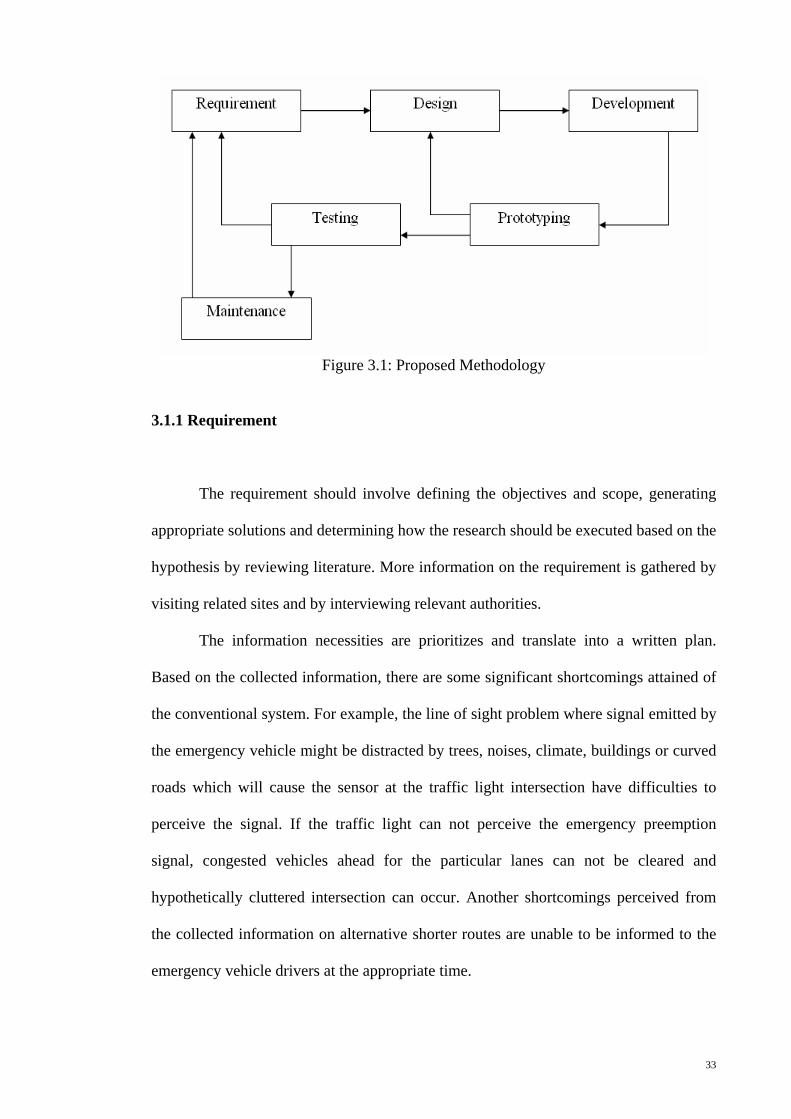
Figure 3.1: Proposed Methodology
3.1.1 Requirement
The requirement should involve defining the objectives and scope, generating
appropriate solutions and determining how the research should be executed based on the
hypothesis by reviewing literature. More information on the requirement is gathered by
visiting related sites and by interviewing relevant authorities.
The information necessities are prioritizes and translate into a written plan.
Based on the collected information, there are some significant shortcomings attained of
the conventional system. For example, the line of sight problem where signal emitted by
the emergency vehicle might be distracted by trees, noises, climate, buildings or curved
roads which will cause the sensor at the traffic light intersection have difficulties to
perceive the signal. If the traffic light can not perceive the emergency preemption
signal, congested vehicles ahead for the particular lanes can not be cleared and
hypothetically cluttered intersection can occur. Another shortcomings perceived from
the collected information on alternative shorter routes are unable to be informed to the
emergency vehicle drivers at the appropriate time.
33
3.1.2 Design
Based on the Requirement phase, a proposed idea is constructed. Design aspect
is a stage that illustrates a basic thought of how the project system will function. As
stated in the Requirement stage, line of sight quandary contributes to current emergency
preemption system problem. For that reason, the use of GPS technology is proposed to
overcome the drawback of cluttered intersection and shorter alternatives routes. The
design can be divided into software and hardware part.
The software part concentrates on calculating the suggested route from the
emergency vehicle to their destination. A central system will act independently to
control the traffic lights based on certain threshold set to ensure the emergency vehicle
does not get caught in the road congestion.
The hardware part focuses on the emergency vehicle preemption position, traffic
light controller and wireless transmission. For vehicle preemption position, GPS is used
to track whereabouts of the vehicle is currently situated by obtaining its location. The
location then been sent to the central control by using wireless transmission of GSM.
The central will be responsible to control particular intersections where the emergency
vehicle will maneuver. The central control the intersections by sending GSM output to
the traffic light controller receiver. Based on the central output, the controller will
trigger and calibrate the traffic lights flow.
In this design stage, the idea above will be presented in flow diagrams,
pseudocodes, flowcharts, block diagram and tables.
34
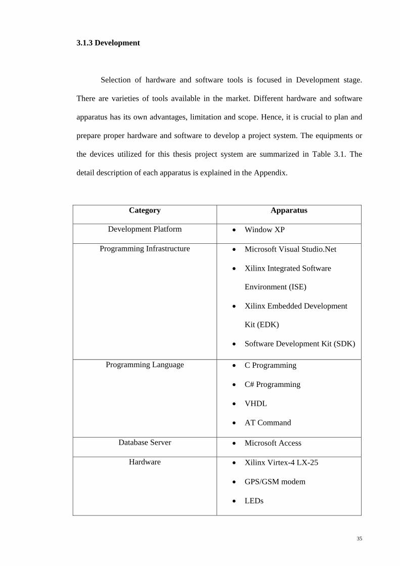
3.1.3 Development
Selection of hardware and software tools is focused in Development stage.
There are varieties of tools available in the market. Different hardware and software
apparatus has its own advantages, limitation and scope. Hence, it is crucial to plan and
prepare proper hardware and software to develop a project system. The equipments or
the devices utilized for this thesis project system are summarized in Table 3.1. The
detail description of each apparatus is explained in the Appendix.
Category Apparatus
Development Platform • Window XP
Programming Infrastructure • Microsoft Visual Studio.Net
• Xilinx Integrated Software
Environment (ISE)
• Xilinx Embedded Development
Kit (EDK)
• Software Development Kit (SDK)
Programming Language • C Programming
• C# Programming
• VHDL
• AT Command
Database Server • Microsoft Access
Hardware • Xilinx Virtex-4 LX-25
• GPS/GSM modem
• LEDs
35
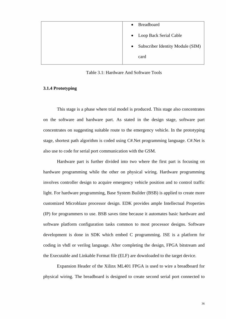
• Breadboard
• Loop Back Serial Cable
• Subscriber Identity Module (SIM)
card
Table 3.1: Hardware And Software Tools
3.1.4 Prototyping
This stage is a phase where trial model is produced. This stage also concentrates
on the software and hardware part. As stated in the design stage, software part
concentrates on suggesting suitable route to the emergency vehicle. In the prototyping
stage, shortest path algorithm is coded using C#.Net programming language. C#.Net is
also use to code for serial port communication with the GSM.
Hardware part is further divided into two where the first part is focusing on
hardware programming while the other on physical wiring. Hardware programming
involves controller design to acquire emergency vehicle position and to control traffic
light. For hardware programming, Base System Builder (BSB) is applied to create more
customized Microblaze processor design. EDK provides ample Intellectual Properties
(IP) for programmers to use. BSB saves time because it automates basic hardware and
software platform configuration tasks common to most processor designs. Software
development is done in SDK which embed C programming. ISE is a platform for
coding in vhdl or verilog language. After completing the design, FPGA bitstream and
the Executable and Linkable Format file (ELF) are downloaded to the target device.
Expansion Header of the Xilinx ML401 FPGA is used to wire a breadboard for
physical wiring. The breadboard is designed to create second serial port connected to
36
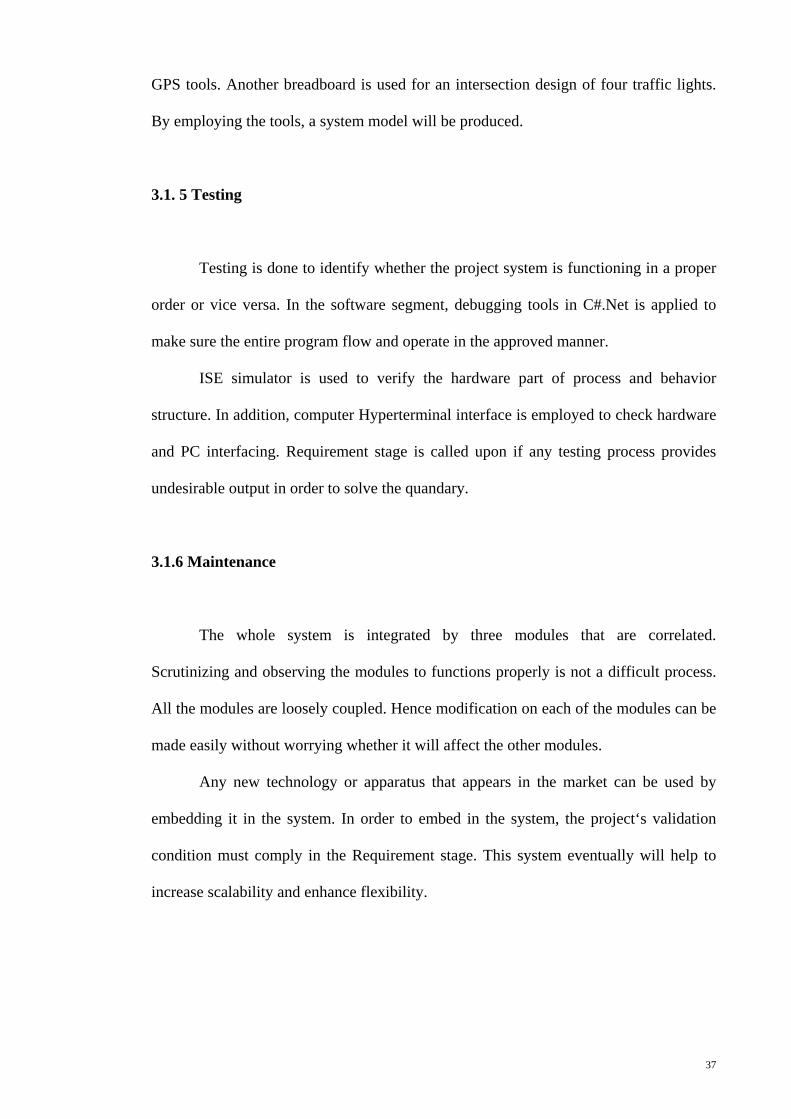
GPS tools. Another breadboard is used for an intersection design of four traffic lights.
By employing the tools, a system model will be produced.
3.1. 5 Testing
Testing is done to identify whether the project system is functioning in a proper
order or vice versa. In the software segment, debugging tools in C#.Net is applied to
make sure the entire program flow and operate in the approved manner.
ISE simulator is used to verify the hardware part of process and behavior
structure. In addition, computer Hyperterminal interface is employed to check hardware
and PC interfacing. Requirement stage is called upon if any testing process provides
undesirable output in order to solve the quandary.
3.1.6 Maintenance
The whole system is integrated by three modules that are correlated.
Scrutinizing and observing the modules to functions properly is not a difficult process.
All the modules are loosely coupled. Hence modification on each of the modules can be
made easily without worrying whether it will affect the other modules.
Any new technology or apparatus that appears in the market can be used by
embedding it in the system. In order to embed in the system, the project‘s validation
condition must comply in the Requirement stage. This system eventually will help to
increase scalability and enhance flexibility.
37
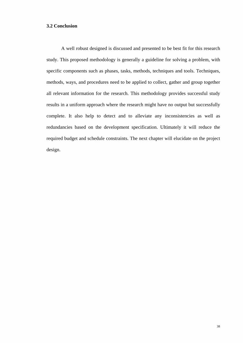
3.2 Conclusion
A well robust designed is discussed and presented to be best fit for this research
study. This proposed methodology is generally a guideline for solving a problem, with
specific components such as phases, tasks, methods, techniques and tools. Techniques,
methods, ways, and procedures need to be applied to collect, gather and group together
all relevant information for the research. This methodology provides successful study
results in a uniform approach where the research might have no output but successfully
complete. It also help to detect and to alleviate any inconsistencies as well as
redundancies based on the development specification. Ultimately it will reduce the
required budget and schedule constraints. The next chapter will elucidate on the project
design.
38
Chapter 4 Problem Verification and System Design
4.0 Introduction
In the earlier chapter of this thesis, high traffic is expected to cause emergency vehicle
to get caught in cluttered intersection problem even though preemption system is
employed. Other problem includes the green traffic light is not triggered based on the
route that the emergency vehicle is heading. These typical preemption system
drawbacks will be verified in the following sections by using data collection and
observation method at the traffic intersection site. The data collection is taken from
streets in Petaling Jaya. The first data collection is made by observing traffic light
changes in several intersections. The purpose of this observation is to come out with the
phase design for the selected intersections. Based on the phase design and other
observation, a new preemption system is proposed to alleviate the identified quandaries.
Then, each module of the proposed system is illustrated in diagrams and flowcharts.
39
4.1 Real Time Traffic intersection Analysis
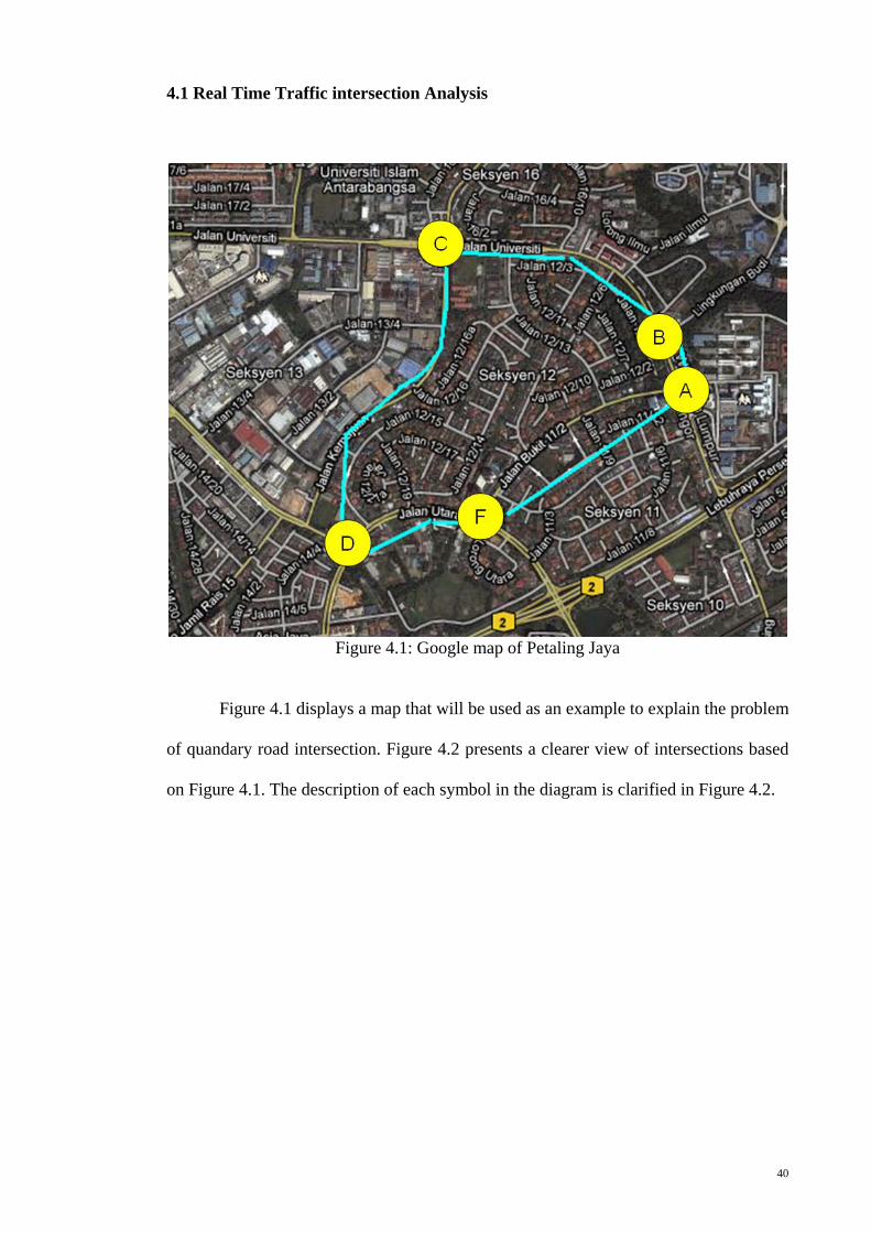
Figure 4.1: Google map of Petaling Jaya
Figure 4.1 displays a map that will be used as an example to explain the problem
of quandary road intersection. Figure 4.2 presents a clearer view of intersections based
on Figure 4.1. The description of each symbol in the diagram is clarified in Figure 4.2.
40
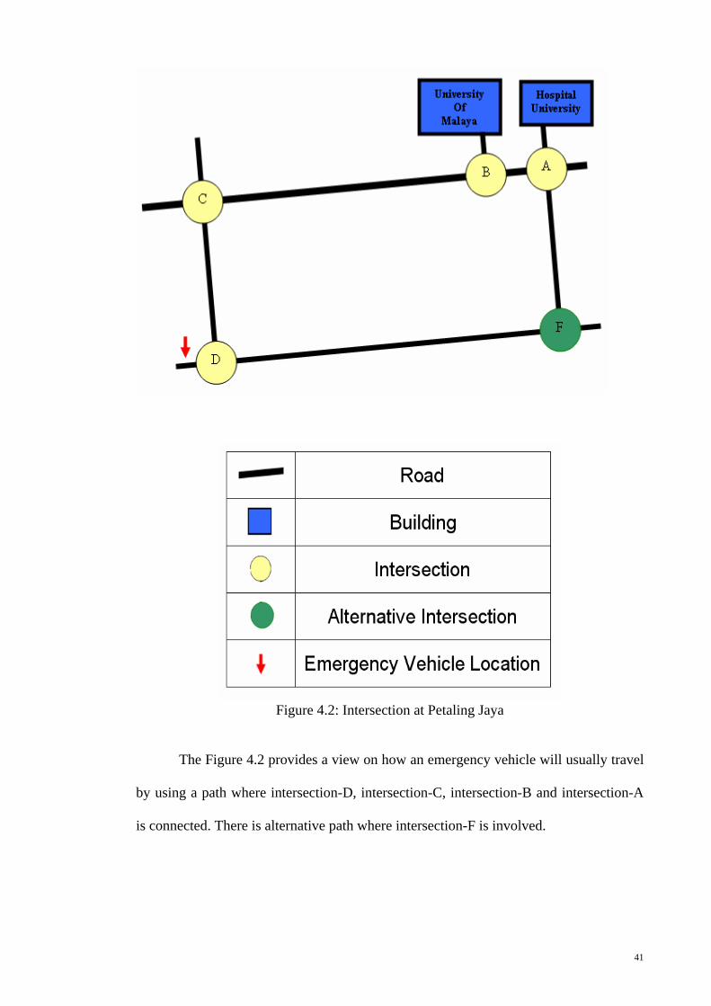
Figure 4.2: Intersection at Petaling Jaya
The Figure 4.2 provides a view on how an emergency vehicle will usually travel
by using a path where intersection-D, intersection-C, intersection-B and intersection-A
is connected. There is alternative path where intersection-F is involved.
41
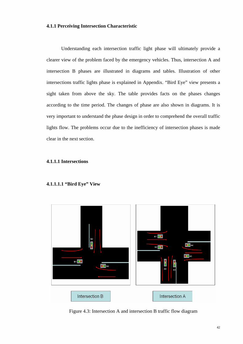
4.1.1 Perceiving Intersection Characteristic
Understanding each intersection traffic light phase will ultimately provide a
clearer view of the problem faced by the emergency vehicles. Thus, intersection A and
intersection B phases are illustrated in diagrams and tables. Illustration of other
intersections traffic lights phase is explained in Appendix. “Bird Eye” view presents a
sight taken from above the sky. The table provides facts on the phases changes
according to the time period. The changes of phase are also shown in diagrams. It is
very important to understand the phase design in order to comprehend the overall traffic
lights flow. The problems occur due to the inefficiency of intersection phases is made
clear in the next section.
4.1.1.1 Intersections
4.1.1.1.1 “Bird Eye” View
Figure 4.3: Intersection A and intersection B traffic flow diagram
42
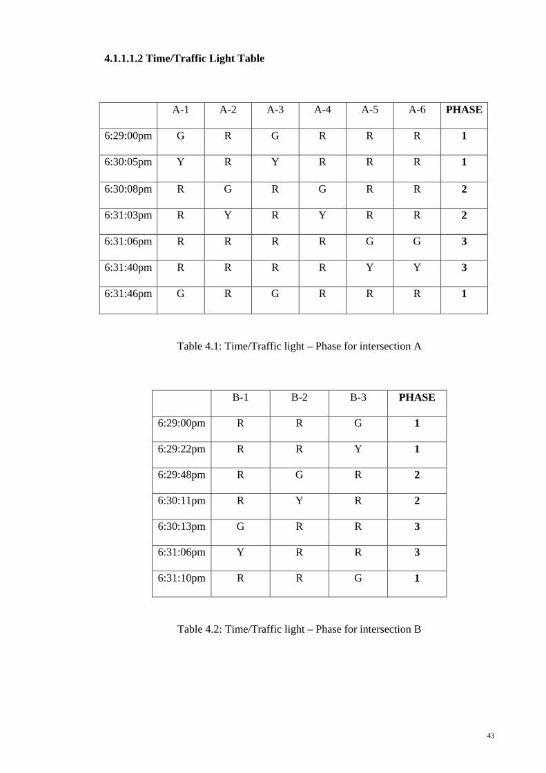
4.1.1.1.2 Time/Traffic Light Table
A-1 A-2 A-3 A-4 A-5 A-6 PHASE
6:29:00pm G R G R R R 1
6:30:05pm Y R Y R R R 1
6:30:08pm R G R G R R 2
6:31:03pm R Y R Y R R 2
6:31:06pm R R R R G G 3
6:31:40pm R R R R Y Y 3
6:31:46pm G R G R R R 1
Table 4.1: Time/Traffic light – Phase for intersection A
B-1 B-2 B-3 PHASE
6:29:00pm R R G 1
6:29:22pm R R Y 1
6:29:48pm R G R 2
6:30:11pm R Y R 2
6:30:13pm G R R 3
6:31:06pm Y R R 3
6:31:10pm R R G 1
Table 4.2: Time/Traffic light – Phase for intersection B
43
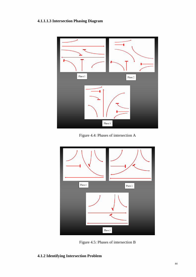
4.1.1.1.3 Intersection Phasing Diagram
Figure 4.4: Phases of intersection A
Figure 4.5: Phases of intersection B
4.1.2 Identifying Intersection Problem
44
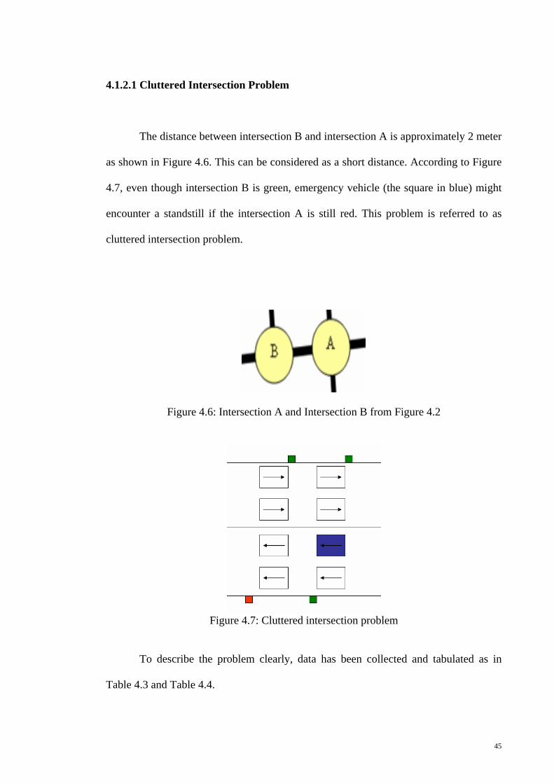
4.1.2.1 Cluttered Intersection Problem
The distance between intersection B and intersection A is approximately 2 meter
as show
n in Figure 4.6. This can be considered as a short distance. According to Figure
4.7, even though intersection B is green, emergency vehicle (the square in blue) might
encounter a standstill if the intersection A is still red. This problem is referred to as
cluttered intersection problem.
Figure 4.6: Intersection A and Intersection B from Figure 4.2
Figure 4.7: Cluttered intersection problem
To describe the problem clearly, data has been collected and tabulated as in
Table 4.3 and Table 4.4.
45
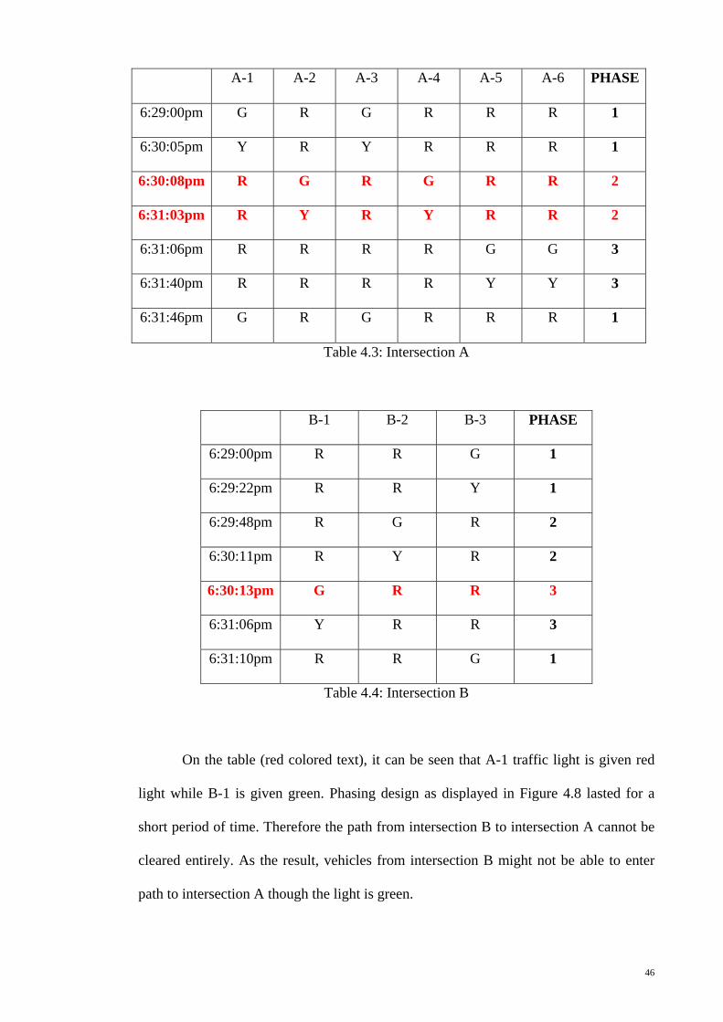
A-1 A-2 A-3 A-4 A-5 A-6 PHASE
6:29:00pm G R G R R R 1
6:30:05pm Y R Y R R R 1
6:30:08pm R G R G R R 2
6:31:03pm R Y R Y R R 2
6:31:06pm R R R R G G 3
6:31:40pm R R R R Y Y 3
6:31:46pm G R G R R R 1
Table 4.3: Intersection A
B-1 B-2 B-3 PHASE
6:29:00pm R R G 1
6:29:22pm R R Y 1
6:29:48pm R G R 2
6:30:11pm R Y R 2
6:30:13pm G R R 3
6:31:06pm Y R R 3
6:31:10pm R R G 1
Table 4.4: I rsection B
On the table (red colored text), it can be seen that A-1 traffic light is given red
nte
light while B-1 is given green. Phasing design as displayed in Figure 4.8 lasted for a
short period of time. Therefore the path from intersection B to intersection A cannot be
cleared entirely. As the result, vehicles from intersection B might not be able to enter
path to intersection A though the light is green.
46
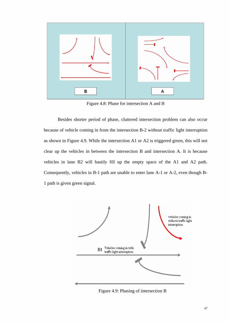
Figure 4.8: Phase for intersection A and B
Besides shorter period of phase, cluttered intersection problem can also occur
because of vehicle coming in from the intersection B-2 without traffic light interruption
as shown in Figure 4.9. While the intersection A1 or A2 is triggered green, this will not
clear up the vehicles in between the intersection B and intersection A. It is because
vehicles in lane B2 will hastily fill up the empty space of the A1 and A2 path.
Consequently, vehicles in B-1 path are unable to enter lane A-1 or A-2, even though B-
1 path is given green signal.
Figure 4.9: Phasing of intersection B
47
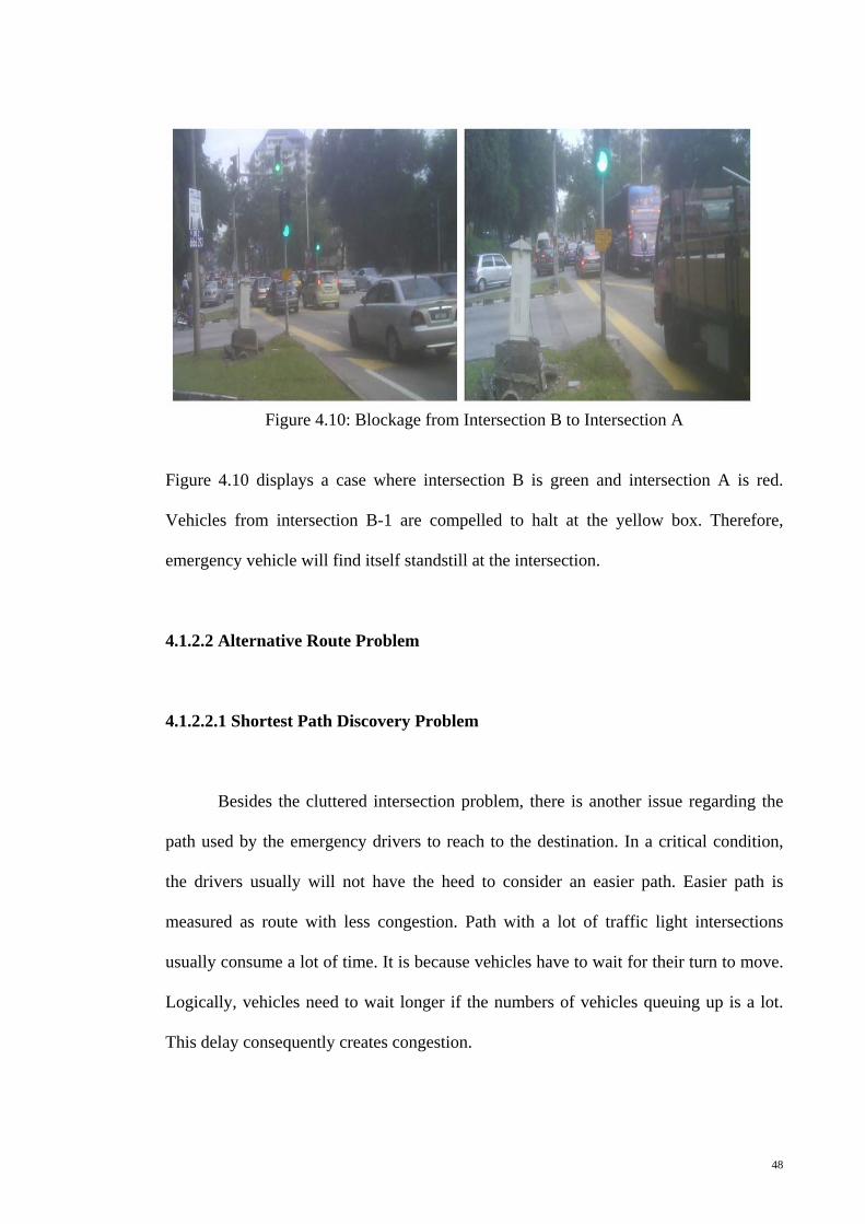
Figure 4.10: Blockage from Intersection B to Intersection A
Figure 4.10 displays a case where intersection B is green and intersection A is red.
Vehicles from intersection B-1 are compelled to halt at the yellow box. Therefore,
emergency vehicle will find itself standstill at the intersection.
4.1.2.2 Alternative Route Problem
4.1.2.2.1 Shortest Path Discovery Problem
Besides the cluttered intersection problem, there is another issue regarding the
path used by the emergency drivers to reach to the destination. In a critical condition,
the drivers usually will not have the heed to consider an easier path. Easier path is
measured as route with less congestion. Path with a lot of traffic light intersections
usually consume a lot of time. It is because vehicles have to wait for their turn to move.
Logically, vehicles need to wait longer if the numbers of vehicles queuing up is a lot.
This delay consequently creates congestion.
48
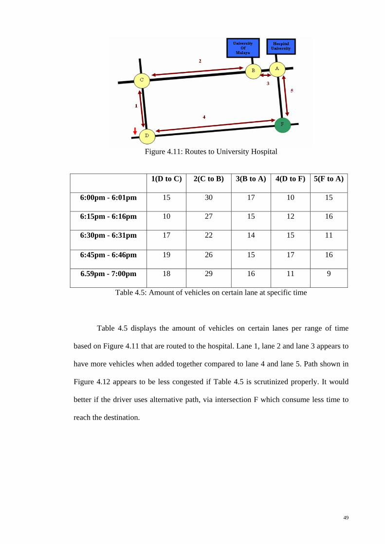
Figure 4.11: Routes to University Hospital
1(D to C) 2(C to B) 3(B to A) 4(D to F) 5(F to A)
6:00pm - 6:01pm 15 30 17 10 15
6:15pm - 6:16pm 10 27 15 12 16
6:30pm - 6:31pm 17 22 14 15 11
6:45pm - 6:46pm 19 26 15 17 16
6.59pm - 7:00pm 18 29 16 11 9
Table 4.5: Amount of vehicles on certain lane at specific time
Table 4.5 displays the amount of vehicles on certain lanes per range of time
based on Figure 4.11 that are routed to the hospital. Lane 1, lane 2 and lane 3 appears to
have more vehicles when added together compared to lane 4 and lane 5. Path shown in
Figure 4.12 appears to be less congested if Table 4.5 is scrutinized properly. It would
better if the driver uses alternative path, via intersection F which consume less time to
reach the destination.
49
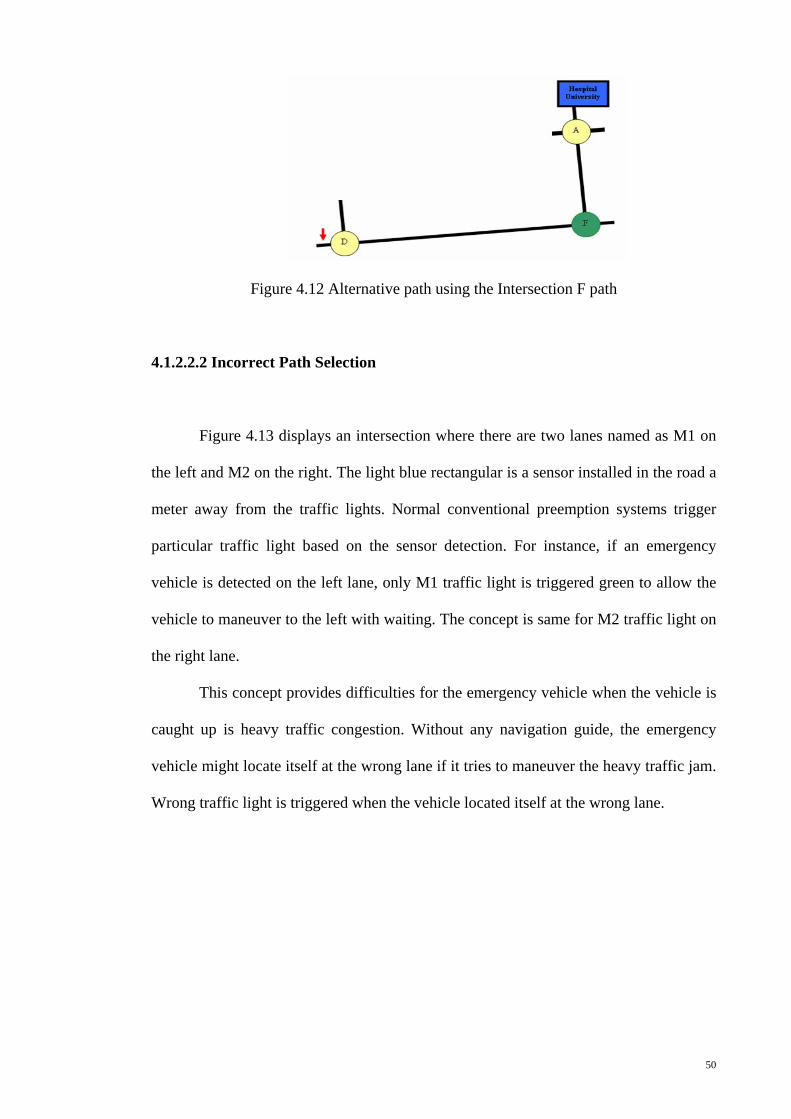
Figure 4.12 Alternative path using the Intersection F path
4.1.2.2.2 Incorrect Path Selection
Figure 4.13 displays an intersection where there are two lanes named as M1 on
the left and M2 on the right. The light blue rectangular is a sensor installed in the road a
meter away from the traffic lights. Normal conventional preemption systems trigger
particular traffic light based on the sensor detection. For instance, if an emergency
vehicle is detected on the left lane, only M1 traffic light is triggered green to allow the
vehicle to maneuver to the left with waiting. The concept is same for M2 traffic light on
the right lane.
This concept provides difficulties for the emergency vehicle when the vehicle is
caught up is heavy traffic congestion. Without any navigation guide, the emergency
vehicle might locate itself at the wrong lane if it tries to maneuver the heavy traffic jam.
Wrong traffic light is triggered when the vehicle located itself at the wrong lane.
50
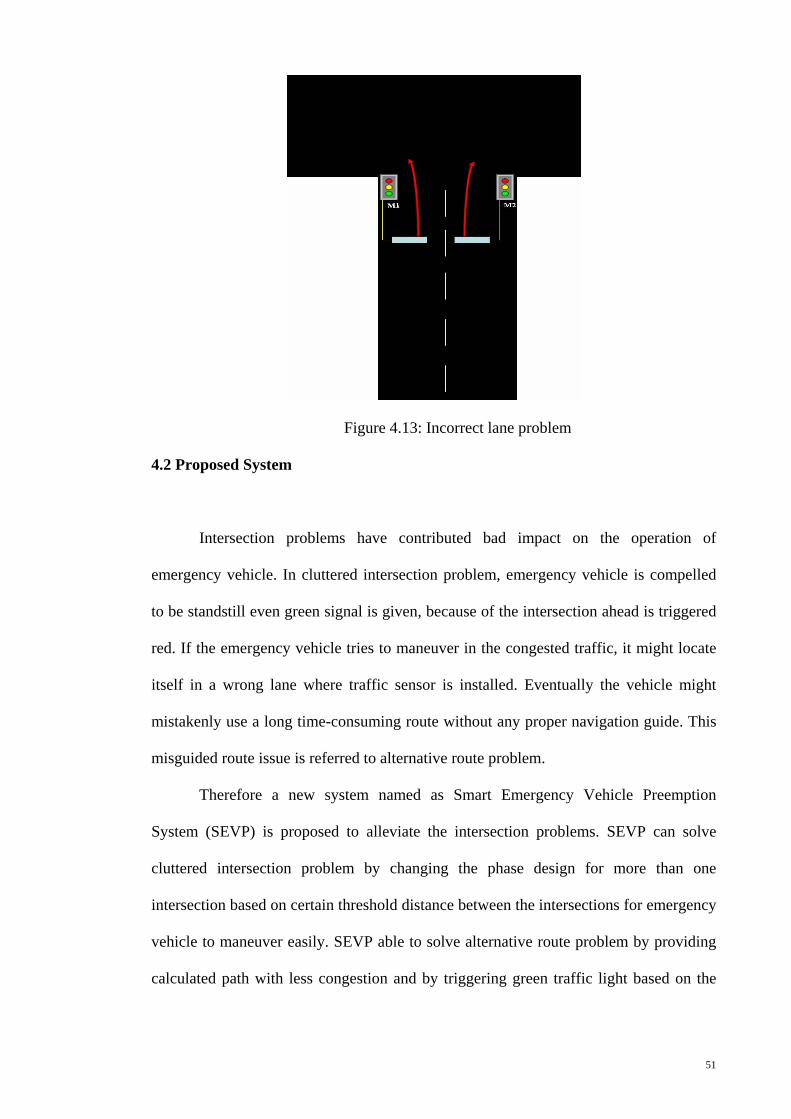
Figure 4.13: Incorrect lane problem
4.2 Proposed System
Intersection problems have contributed bad impact on the operation of
emergency vehicle. In cluttered intersection problem, emergency vehicle is compelled
to be standstill even green signal is given, because of the intersection ahead is triggered
red. If the emergency vehicle tries to maneuver in the congested traffic, it might locate
itself in a wrong lane where traffic sensor is installed. Eventually the vehicle might
mistakenly use a long time-consuming route without any proper navigation guide. This
misguided route issue is referred to alternative route problem.
Therefore a new system named as Smart Emergency Vehicle Preemption
System (SEVP) is proposed to alleviate the intersection problems. SEVP can solve
cluttered intersection problem by changing the phase design for more than one
intersection based on certain threshold distance between the intersections for emergency
vehicle to maneuver easily. SEVP able to solve alternative route problem by providing
calculated path with less congestion and by triggering green traffic light based on the
51
route that the emergency vehicle is heading as well as directing the emergency vehicle
to be in the correct lane before reaching the intersection.
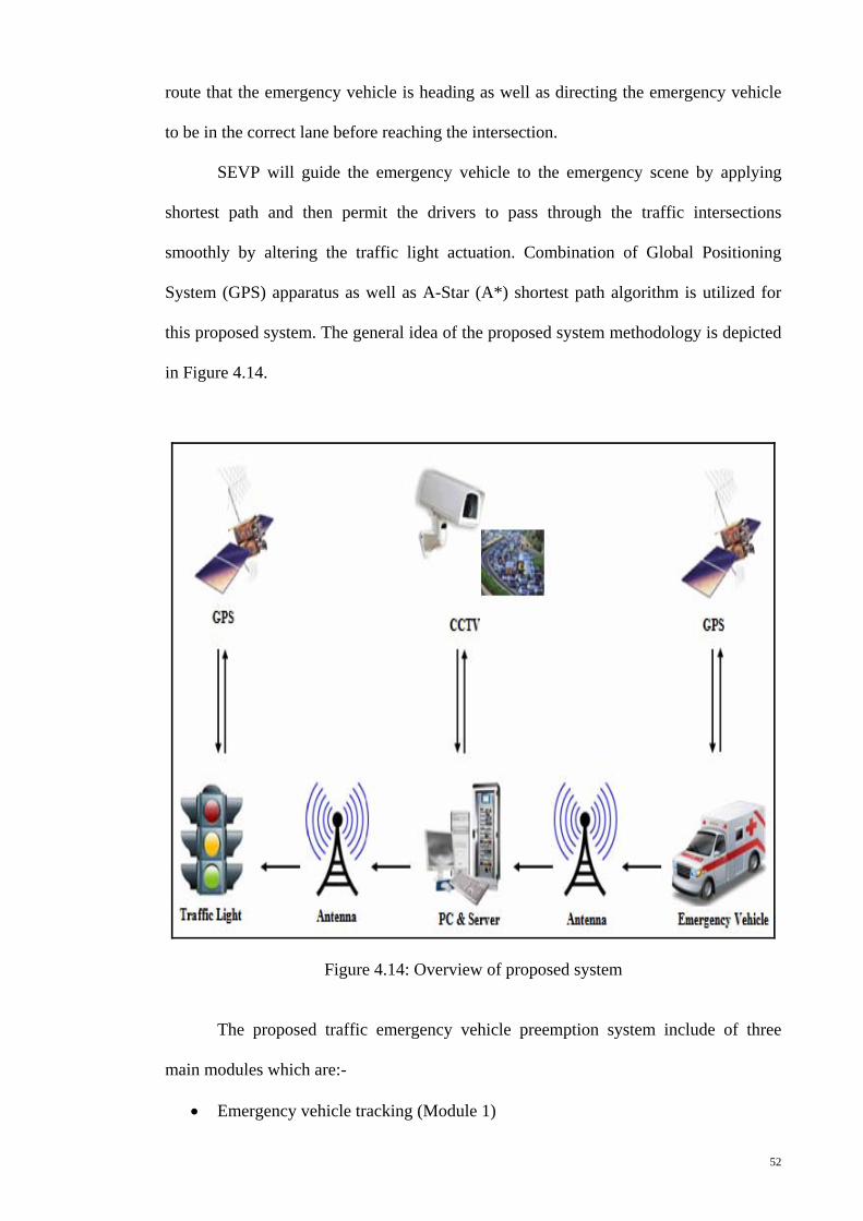
SEVP will guide the emergency vehicle to the emergency scene by applying
shortest path and then permit the drivers to pass through the traffic intersections
smoothly by altering the traffic light actuation. Combination of Global Positioning
System (GPS) apparatus as well as A-Star (A*) shortest path algorithm is utilized for
this proposed system. The general idea of the proposed system methodology is depicted
in Figure 4.14.
Figure 4.14: Overview of proposed system
The proposed traffic emergency vehicle preemption system include of three
main modules which are:-
• Emergency vehicle tracking (Module 1)
52
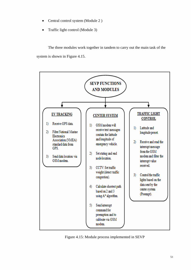
• Central control system (Module 2 )
• Traffic light control (Module 3)
The three modules work together in tandem to carry out the main task of the
system is shown in Figure 4.15.
Figure 4.15: Module process implemented in SEVP
53
4.3 Scenario Example
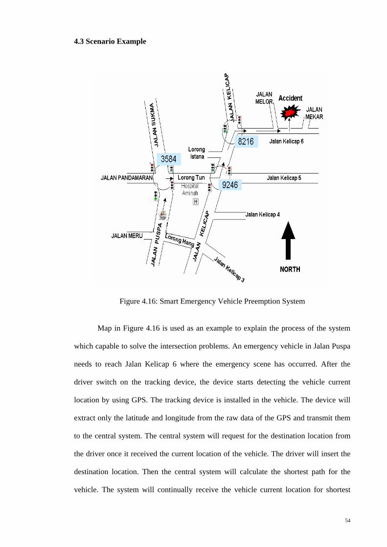
Figure 4.16: Smart Emergency Vehicle Preemption System
Map in Figure 4.16 is used as an example to explain the process of the system
which capable to solve the intersection problems. An emergency vehicle in Jalan Puspa
needs to reach Jalan Kelicap 6 where the emergency scene has occurred. After the
driver switch on the tracking device, the device starts detecting the vehicle current
location by using GPS. The tracking device is installed in the vehicle. The device will
extract only the latitude and longitude from the raw data of the GPS and transmit them
to the central system. The central system will request for the destination location from
the driver once it received the current location of the vehicle. The driver will insert the
destination location. Then the central system will calculate the shortest path for the
vehicle. The system will continually receive the vehicle current location for shortest
54
path calculation until the vehicle reaches the destination. By iteratively calculating, any
congestion path can be detected earlier to avoid to the driver to use the path which
previously recommended by the central system.
According to the map, the level of congestion in Lorong Hang is higher then
Lorong Tun. Therefore the system will direct the vehicle to use Lorong Tun instead of
Lorong Hang. Each intersection will have a unique GSM number (i.e. 3584, 9246 and
8216) so that the central system can send interrupt signal to specific intersections. Once
the vehicle is sensed in an intersection radius, the system will alter the intersection
traffic lights phasing earlier for the emergency vehicle to pass through the intersection
without any interruption. The intersection radius is approximately 200 meters. The
system had set a distance threshold where the distance is about one kilometer. If the
distance of each adjacent intersection is within the threshold distance, the particular
intersections will be triggered green at once to avoid cluttered intersections problem.
For example, intersection 9246 and intersection 8216 distance is less than one
kilometer. Therefore, the intersections phasing design is altered at once. Early traffic
light triggering provides navigation for the emergency vehicle. In this way, the vehicle
will obtain a clearer view when driving and eventually avoid the alternative path
problem. Once the vehicle had pass through an intersection, that particular intersection
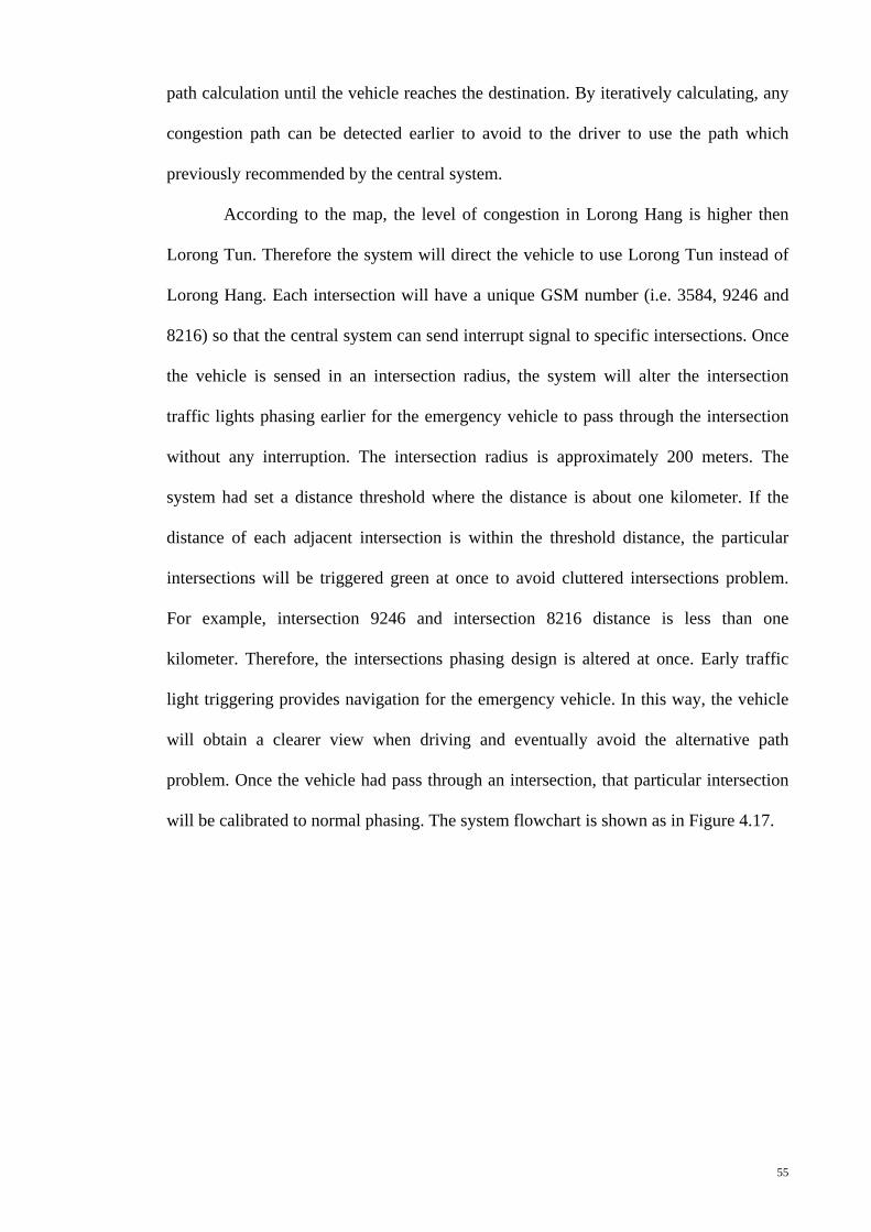
will be calibrated to normal phasing. The system flowchart is shown as in Figure 4.17.
55
Figure 4.17: System Flow Chart
56
4.4 Conclusion
Normal traffic light phasing design contributes quandaries for emergency
vehicles. Therefore, traffic phase design information has been collected and scrutinized
from several intersections site. Based on the result, problems faced by the emergency
vehicle are identified. The problem is divided as cluttered intersection and alternative
path problem. To alleviate this problem, a new system named as SEVP is proposed.
SEVP solve intersection problems by providing calculated path with less congestion
and directing the emergency vehicle to be in the path before reaching the intersection.
Green signal is triggered based on the distance threshold set between each intersections.
The SEVP operation is elucidates in three modules. In the module 1, it discussed the
method used to perceive the emergency vehicle location. With this diagnostic location
information, the process of module 2 which is the central control system is explained.
Then, the traffic lights intersection controller actuation process is clarified for module 3.
A scenario example is used to clarify the ability of SEVP to solve the problem.
57
Chapter 5 System Implementation
5.0 Introduction
Smart Emergency Vehicle Preemption system (SEVP) includes three modules.
They are emergency vehicle tracking (Module 1), central control system (Module 2),
and traffic light control (Module 3). Module 1 explains the process of attaining and
sending the emergency vehicle current location to the central system. In module 2, the
obtained location is calculated to provide best path from the emergency vehicle position
to the emergency scene. The best path is referred to as route that consume less time. The
calculated shortest path result is used to disrupt several traffic intersections within range
set using n radius threshold of the emergency vehicle position in the emergency route
path. The traffic lights disruption is done by transmitting interrupt signals to the
particular intersection controllers. These traffic light controllers in module 3 will control
and calibrate the traffic light phase to permit or to grant green light for the emergency
vehicle. In this chapter, each module clearly presents its discussion and result. A
scenario example is used to show how the system calculates the path based on its
congestion weight.
5.1 Emergency Vehicle Tracking (Module 1)
5.1.1 Module 1 Discussion
Vehicle location is obtained by the central of the system to calculate the shortest
path from the emergency vehicle position to the emergency scene. To track the location,
Global Positioning System (GPS) technology is used. GPS receiver communication is
58
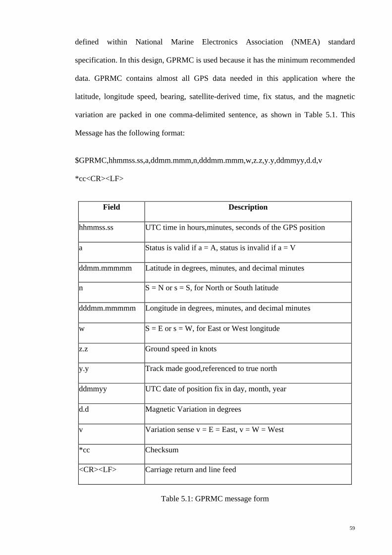
defined within National Marine Electronics Association (NMEA) standard
specification. In this design, GPRMC is used because it has the minimum recommended
data. GPRMC contains almost all GPS data needed in this application where the
latitude, longitude speed, bearing, satellite-derived time, fix status, and the magnetic
variation are packed in one comma-delimited sentence, as shown in Table 5.1. This
Message has the following format:
$GPRMC,hhmmss.ss,a,ddmm.mmm,n,dddmm.mmm,w,z.z,y.y,ddmmyy,d.d,v
*cc<CR><LF>
Field Description
hhmmss.ss UTC time in hours,minutes, seconds of the GPS position
a Status is valid if a = A, status is invalid if a = V
ddmm.mmmmm Latitude in degrees, minutes, and decimal minutes
n S = N or s = S, for North or South latitude
dddmm.mmmmm Longitude in degrees, minutes, and decimal minutes
w S = E or s = W, for East or West longitude
z.z Ground speed in knots
y.y Track made good,referenced to true north
ddmmyy UTC date of position fix in day, month, year
d.d Magnetic Variation in degrees
v Variation sense v = E = East, v = W = West
*cc Checksum
<CR><LF> Carriage return and line feed
Table 5.1: GPRMC message form
59
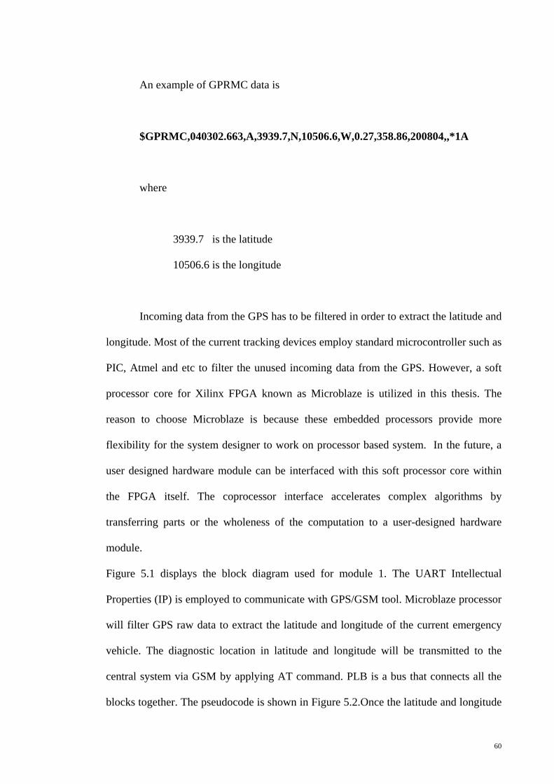
An example of GPRMC data is
$GPRMC,040302.663,A,3939.7,N,10506.6,W,0.27,358.86,200804,,*1A
where
3939.7 is the latitude
10506.6 is the longitude
Incoming data from the GPS has to be filtered in order to extract the latitude and
longitude. Most of the current tracking devices employ standard microcontroller such as
PIC, Atmel and etc to filter the unused incoming data from the GPS. However, a soft
processor core for Xilinx FPGA known as Microblaze is utilized in this thesis. The
reason to choose Microblaze is because these embedded processors provide more
flexibility for the system designer to work on processor based system. In the future, a
user designed hardware module can be interfaced with this soft processor core within
the FPGA itself. The coprocessor interface accelerates complex algorithms by
transferring parts or the wholeness of the computation to a user-designed hardware
module.
Figure 5.1 displays the block diagram used for module 1. The UART Intellectual
Properties (IP) is employed to communicate with GPS/GSM tool. Microblaze processor
will filter GPS raw data to extract the latitude and longitude of the current emergency
vehicle. The diagnostic location in latitude and longitude will be transmitted to the
central system via GSM by applying AT command. PLB is a bus that connects all the
blocks together. The pseudocode is shown in Figure 5.2.Once the latitude and longitude
60
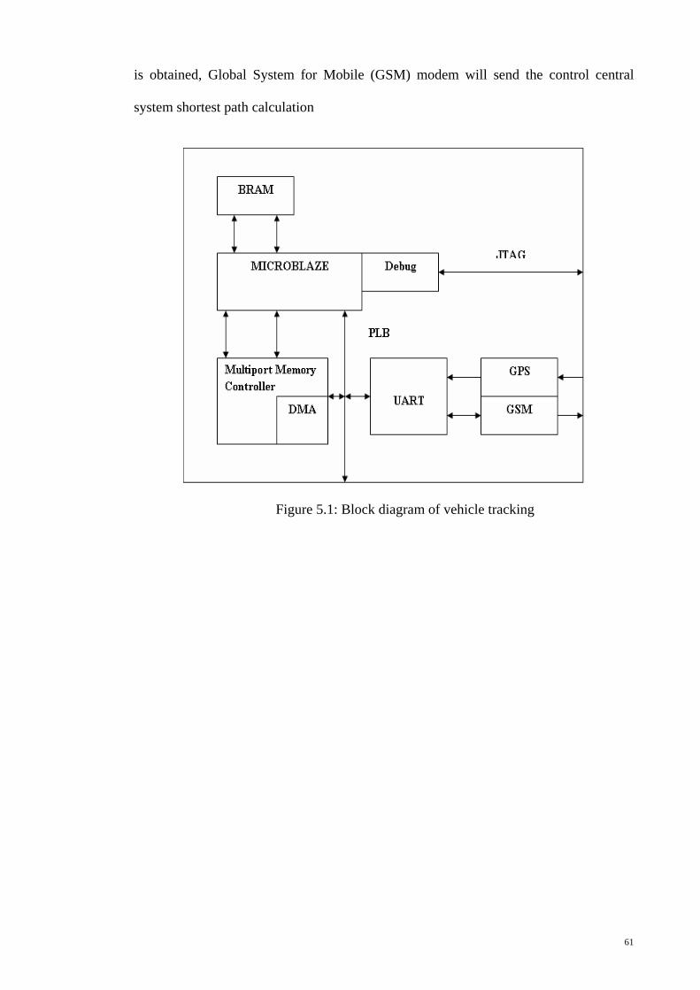
is obtained, Global System for Mobile (GSM) modem will send the control central
system shortest path calculation
Figure 5.1: Block diagram of vehicle tracking
61
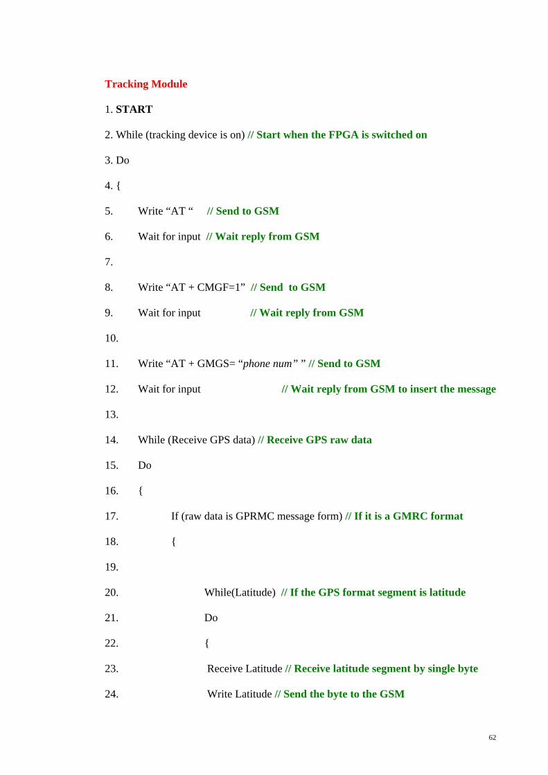
Tracking Module
1. START
2. While (tracking device is on) // Start when the FPGA is switched on
3. Do
4. {
5. Write “AT “ // Send to GSM
6. Wait for input // Wait reply from GSM
7.
8. Write “AT + CMGF=1” // Send to GSM
9. Wait for input // Wait reply from GSM
10.
11. Write “AT + GMGS= “phone num” ” // Send to GSM
12. Wait for input // Wait reply from GSM to insert the message
13.
14. While (Receive GPS data) // Receive GPS raw data
15. Do
16. {
17. If (raw data is GPRMC message form) // If it is a GMRC format
18. {
19.
20. While(Latitude) // If the GPS format segment is latitude
21. Do
22. {
23. Receive Latitude // Receive latitude segment by single byte
24. Write Latitude // Send the byte to the GSM
62
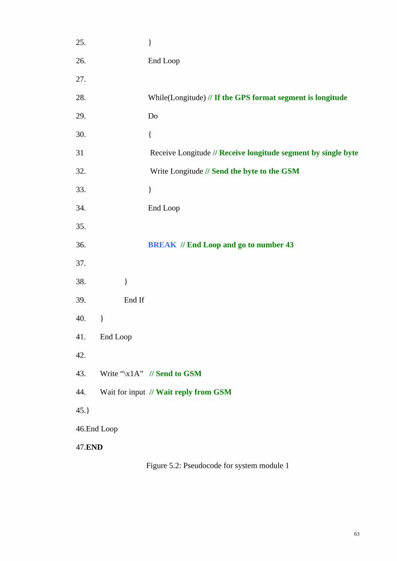
25. }
26. End Loop
27.
28. While(Longitude) // If the GPS format segment is longitude
29. Do
30. {
31 Receive Longitude // Receive longitude segment by single byte
32. Write Longitude // Send the byte to the GSM
33. }
34. End Loop
35.
36. BREAK // End Loop and go to number 43
37.
38. }
39. End If
40. }
41. End Loop
42.
43. Write “\x1A” // Send to GSM
44. Wait for input // Wait reply from GSM
45.}
46.End Loop
47.END
Figure 5.2: Pseudocode for system module 1
63
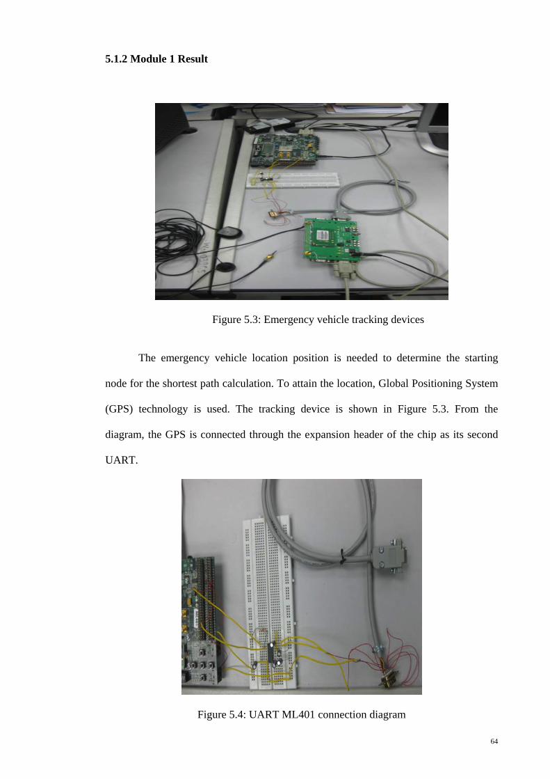
5.1.2 Module 1 Result
Figure 5.3: Emergency vehicle tracking devices
The emergency vehicle location position is needed to determine the starting
node for the shortest path calculation. To attain the location, Global Positioning System
(GPS) technology is used. The tracking device is shown in Figure 5.3. From the
diagram, the GPS is connected through the expansion header of the chip as its second
UART.
Figure 5.4: UART ML401 connection diagram
64
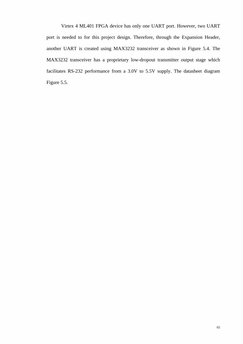
Virtex 4 ML401 FPGA device has only one UART port. However, two UART
port is needed to for this project design. Therefore, through the Expansion Header,
another UART is created using MAX3232 transceiver as shown in Figure 5.4. The
MAX3232 transceiver has a proprietary low-dropout transmitter output stage which
facilitates RS-232 performance from a 3.0V to 5.5V supply. The datasheet diagram
Figure 5.5.
65
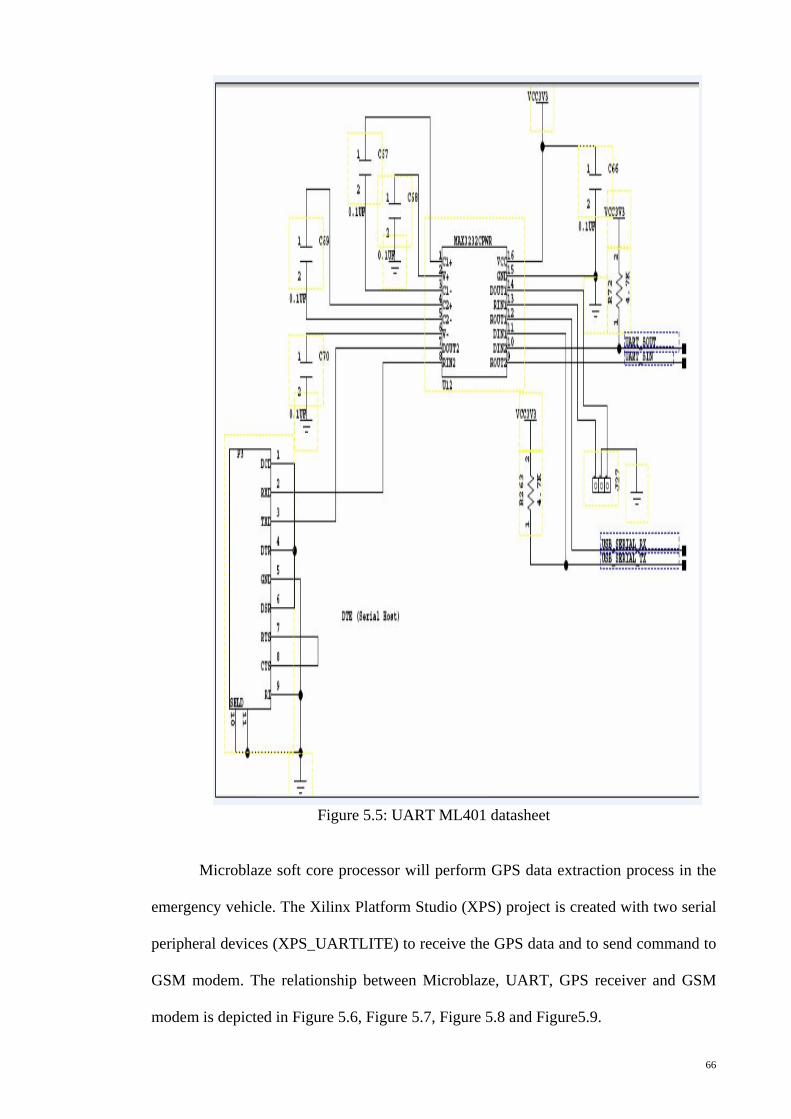
Figure 5.5: UART ML401 datasheet
Microblaze soft core processor will perform GPS data extraction process in the
emergency vehicle. The Xilinx Platform Studio (XPS) project is created with two serial
peripheral devices (XPS_UARTLITE) to receive the GPS data and to send command to
GSM modem. The relationship between Microblaze, UART, GPS receiver and GSM
modem is depicted in Figure 5.6, Figure 5.7, Figure 5.8 and Figure5.9.
66
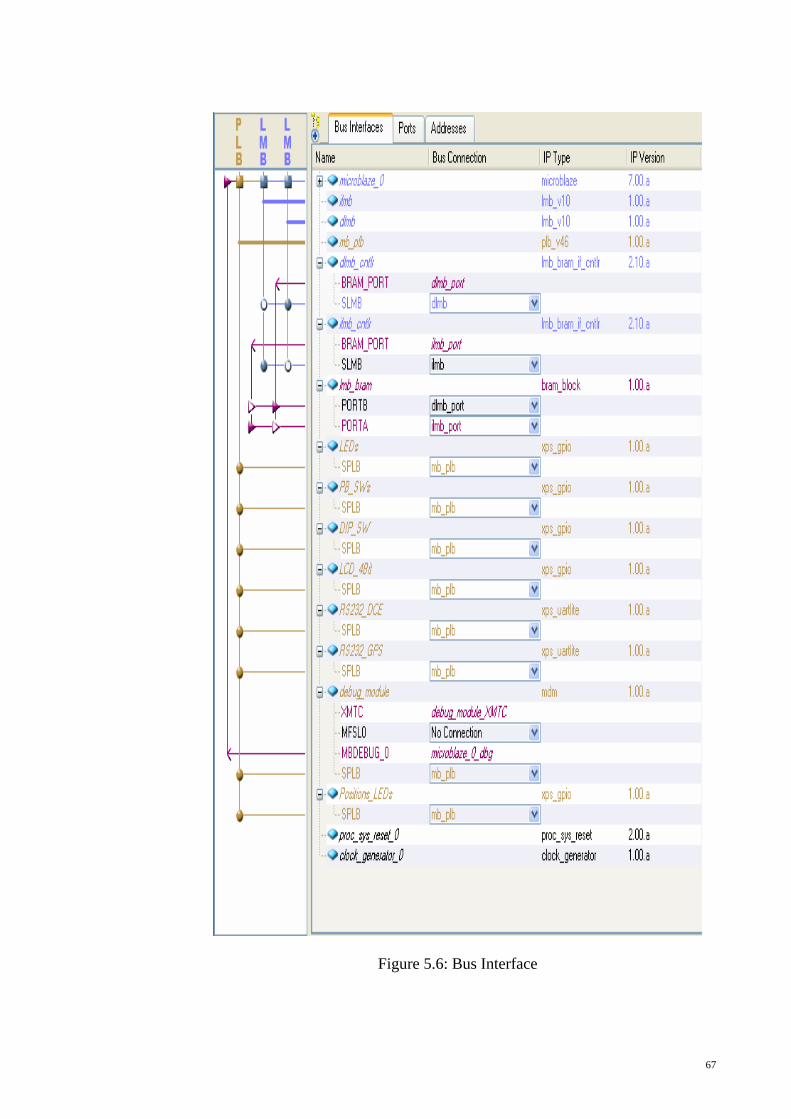
Figure 5.6: Bus Interface
67
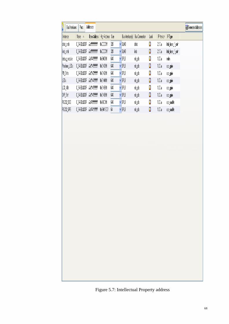
Figure 5.7: Intellectual Property address
68
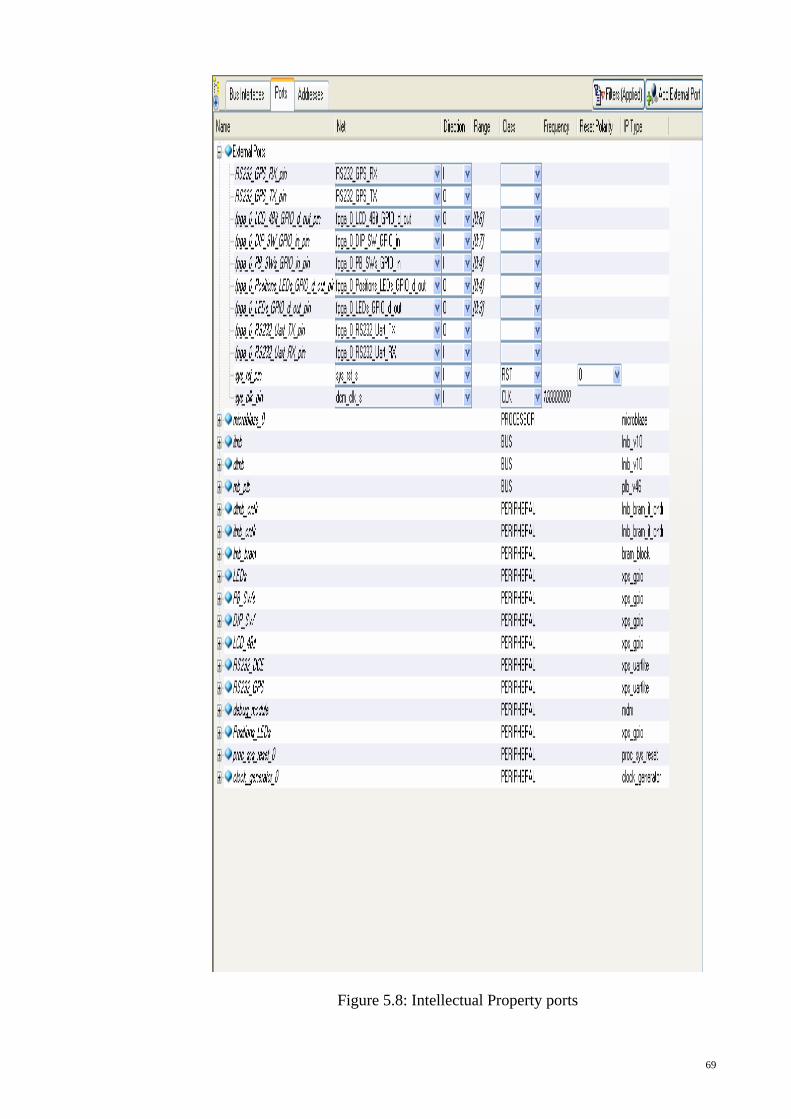
Figure 5.8: Intellectual Property ports
69
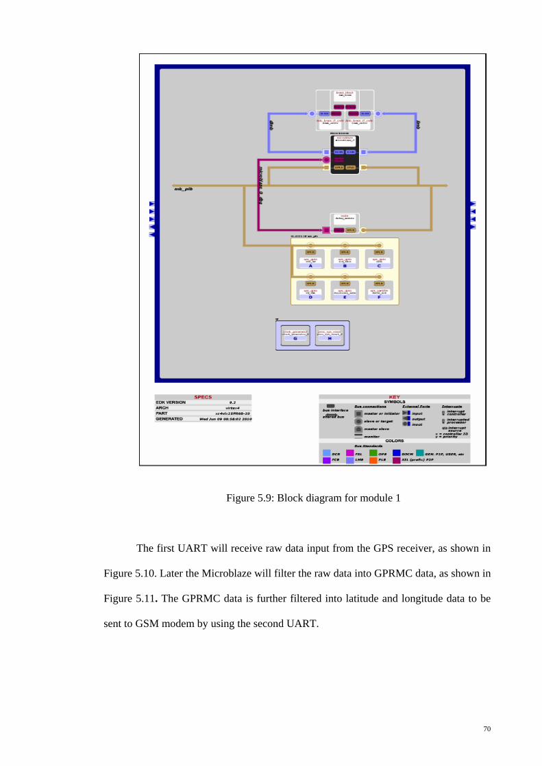
70
Figure 5.9: Block diagram for module 1
The first UART will receive raw data input from the GPS receiver, as shown in
Figure 5.10. Later the Microblaze will filter the raw data into GPRMC data, as shown in
Figure 5.11. The GPRMC data is further filtered into latitude and longitude data to be
sent to GSM modem by using the second UART.
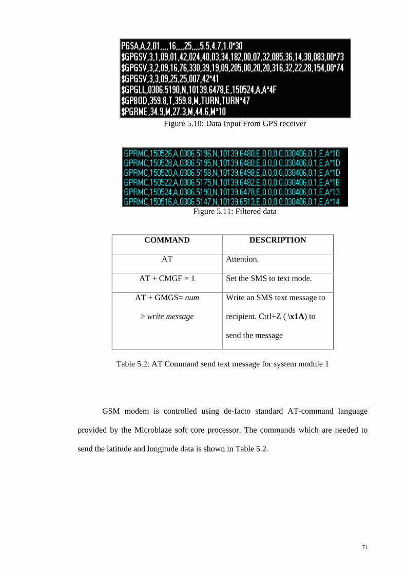
Figure 5.10: Data Input From GPS receiver
Figure 5.11: Filtered data
COMMAND DESCRIPTION
AT Attention.
AT + CMGF = 1 Set the SMS to text mode.
AT + GMGS= num
> write message
Write an SMS text message to
recipient. Ctrl+Z ( \x1A) to
send the message
Table 5.2: AT Command send text message for system module 1
GSM modem is controlled using de-facto standard AT-command language
provided by the Microblaze soft core processor. The commands which are needed to
send the latitude and longitude data is shown in Table 5.2.
71
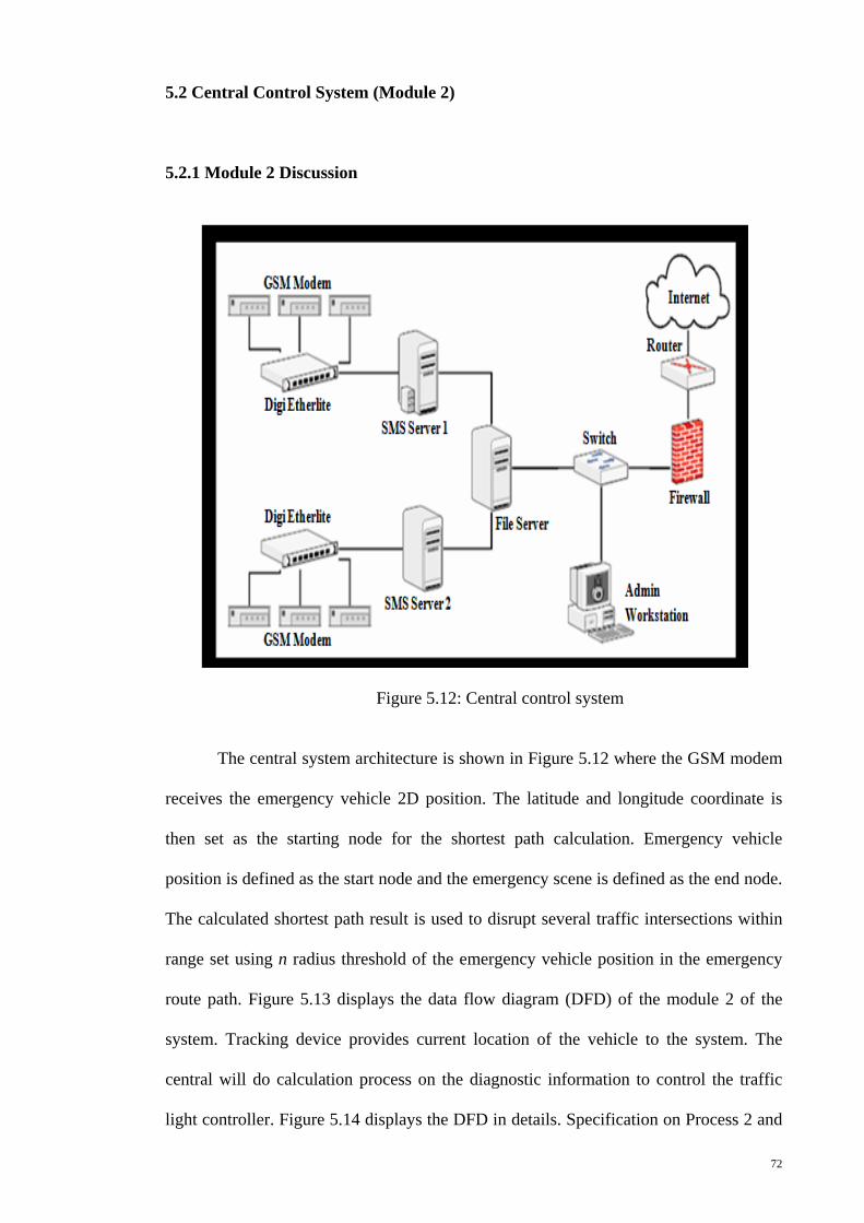
5.2 Central Control System (Module 2)
5.2.1 Module 2 Discussion
Figure 5.12: Central control system
The central system architecture is shown in Figure 5.12 where the GSM modem
receives the emergency vehicle 2D position. The latitude and longitude coordinate is
then set as the starting node for the shortest path calculation. Emergency vehicle
position is defined as the start node and the emergency scene is defined as the end node.
The calculated shortest path result is used to disrupt several traffic intersections within
range set using n radius threshold of the emergency vehicle position in the emergency
route path. Figure 5.13 displays the data flow diagram (DFD) of the module 2 of the
system. Tracking device provides current location of the vehicle to the system. The
central will do calculation process on the diagnostic information to control the traffic
light controller. Figure 5.14 displays the DFD in details. Specification on Process 2 and
72
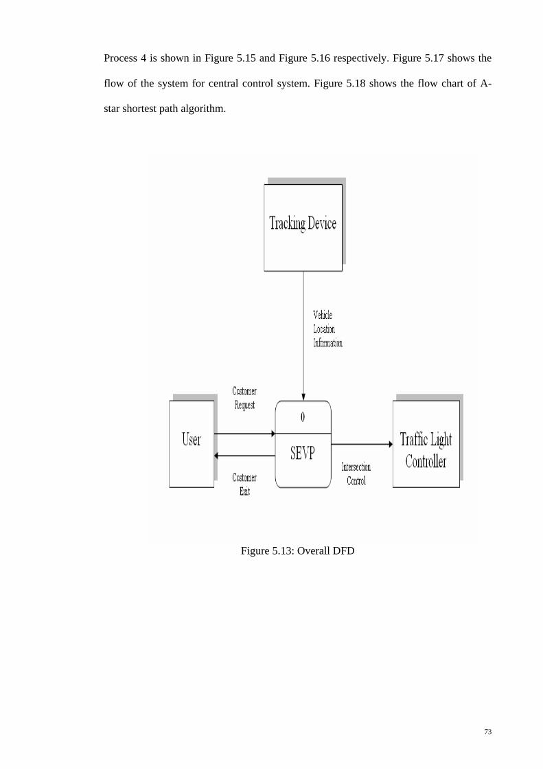
Process 4 is shown in Figure 5.15 and Figure 5.16 respectively. Figure 5.17 shows the
flow of the system for central control system. Figure 5.18 shows the flow chart of A-
star shortest path algorithm.
Figure 5.13: Overall DFD
73
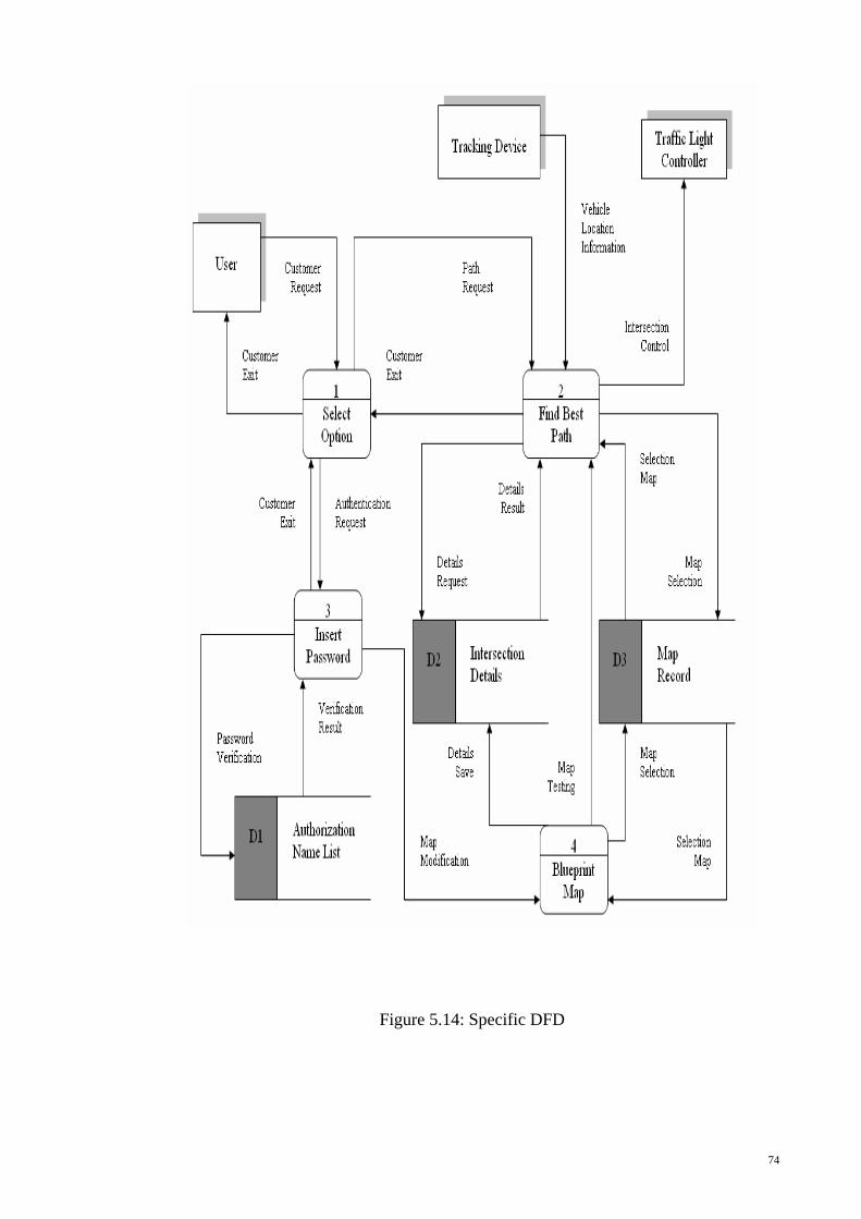
Figure 5.14: Specific DFD
74
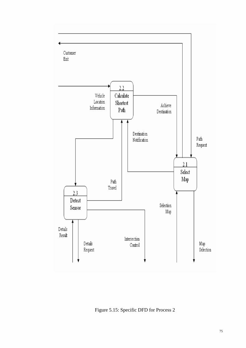
Figure 5.15: Specific DFD for Process 2
75
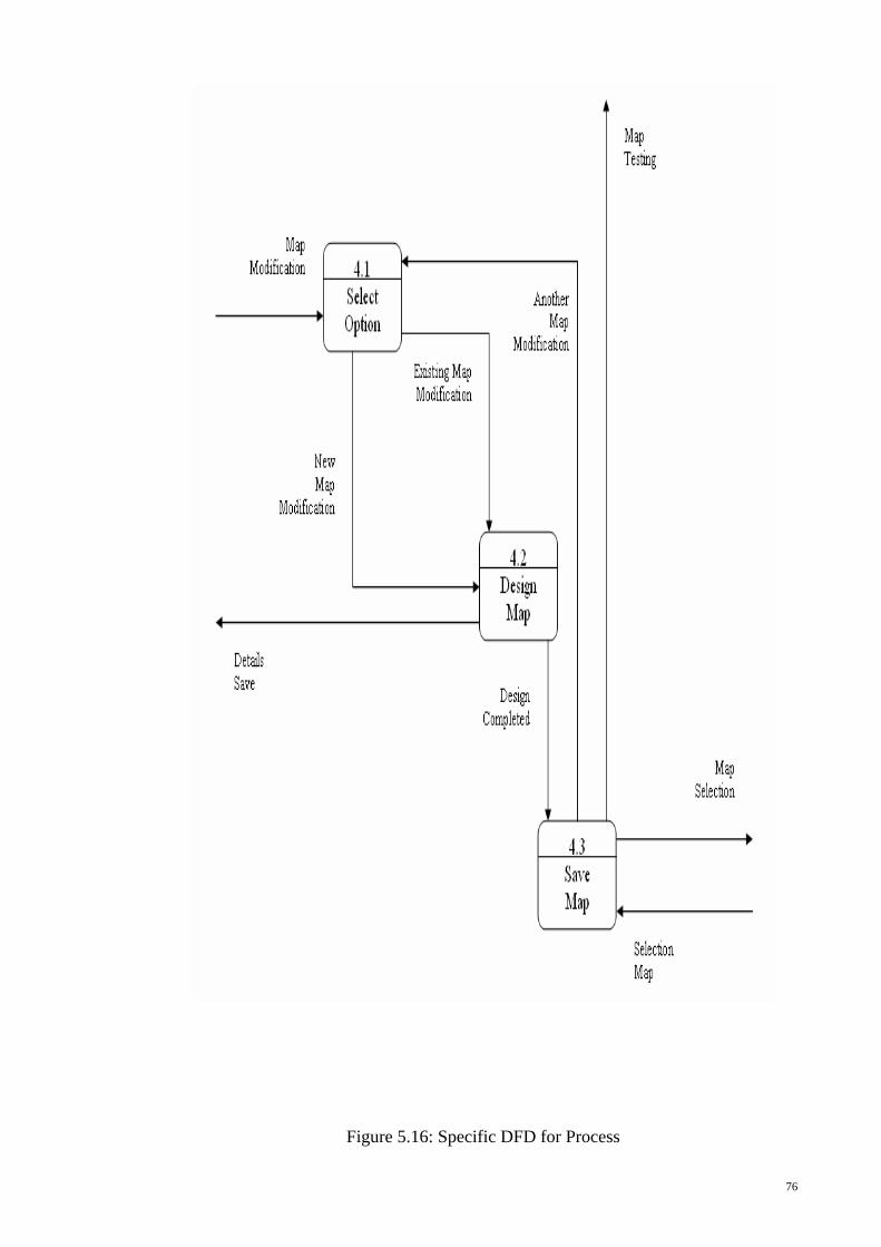
Figure 5.16: Specific DFD for Process
76
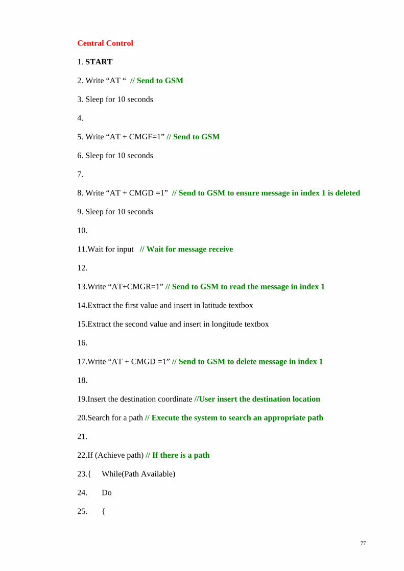
Central Control
1. START
2. Write “AT “ // Send to GSM
3. Sleep for 10 seconds
4.
5. Write “AT + CMGF=1” // Send to GSM
6. Sleep for 10 seconds
7.
8. Write “AT + CMGD =1” // Send to GSM to ensure message in index 1 is deleted
9. Sleep for 10 seconds
10.
11.Wait for input // Wait for message receive
12.
13.Write “AT+CMGR=1” // Send to GSM to read the message in index 1
14.Extract the first value and insert in latitude textbox
15.Extract the second value and insert in longitude textbox
16.
17.Write “AT + CMGD =1” // Send to GSM to delete message in index 1
18.
19.Insert the destination coordinate //User insert the destination location
20.Search for a path // Execute the system to search an appropriate path
21.
22.If (Achieve path) // If there is a path
23.{ While(Path Available)
24. Do
25. {
77
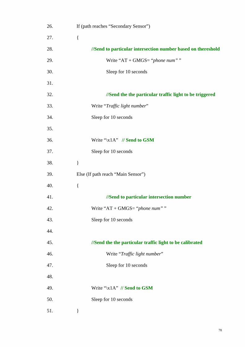
26. If (path reaches “Secondary Sensor”)
27. {
28. //Send to particular intersection number based on thereshold
29. Write “AT + GMGS= “phone num” ”
30. Sleep for 10 seconds
31.
32. //Send the the particular traffic light to be triggered
33. Write “Traffic light number”
34. Sleep for 10 seconds
35.
36. Write “\x1A” // Send to GSM
37. Sleep for 10 seconds
38. }
39. Else (If path reach “Main Sensor”)
40. {
41. //Send to particular intersection number
42. Write “AT + GMGS= “phone num” ”
43. Sleep for 10 seconds
44.
45. //Send the the particular traffic light to be calibrated
46. Write “Traffic light number”
47. Sleep for 10 seconds
48.
49. Write “\x1A” // Send to GSM
50. Sleep for 10 seconds
51. }
78
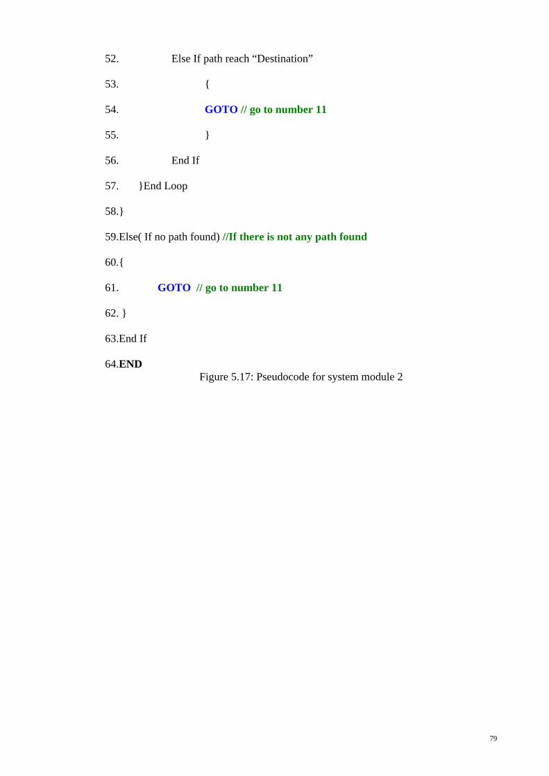
52. Else If path reach “Destination”
53. {
54. GOTO // go to number 11
55. }
56. End If
57. }End Loop
58.}
59.Else( If no path found) //If there is not any path found
60.{
61. GOTO // go to number 11
62. }
63.End If
64.END Figure 5.17: Pseudocode for system module 2
79
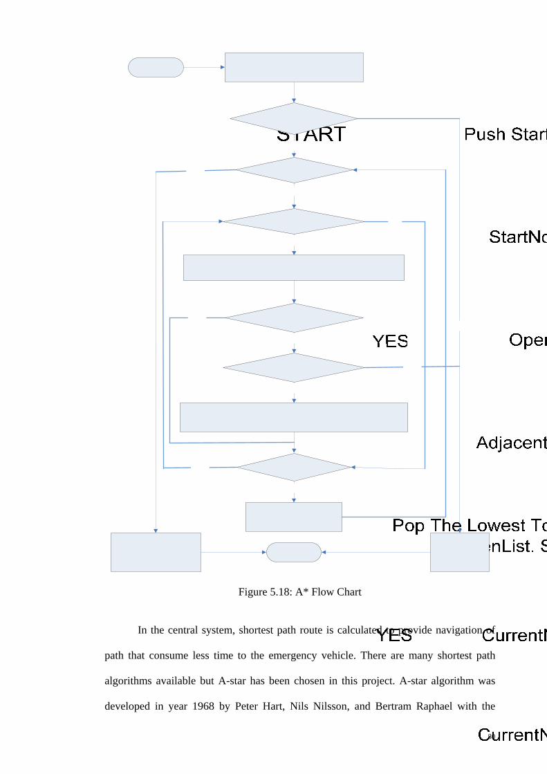
Figure 5.18: A* Flow Chart
In the central system, shortest path route is calculated to provide navigation of
path that consume less time to the emergency vehicle. There are many shortest path
algorithms available but A-star has been chosen in this project. A-star algorithm was
developed in year 1968 by Peter Hart, Nils Nilsson, and Bertram Raphael with the
80
purposed of finding path. A* algorithm has two significant features which are path
scoring and shopping list. In path scoring, the equation “F = G + H” is a key element of
A* as shown in the 8th figure. The variable G represents the movement cost to move
from the starting point A to a given square on the grid, following the path generated to
get there. H is the estimated movement cost to move from that given square on the grid
to the final destination. F is the current estimated shortest path. F is the true shortest
path which is not discovered until the A* algorithm is finished. The algorithm uses
shopping list to determine whether a node need to be calculated or not. The A* structure
consists of two lists: Open and Closed list. The Open list is a list of all cells that have
yet to be saved. The Close list contains the list of all cells that have been saved. Once
the goal is located, the shortest path can easily be obtained.
81
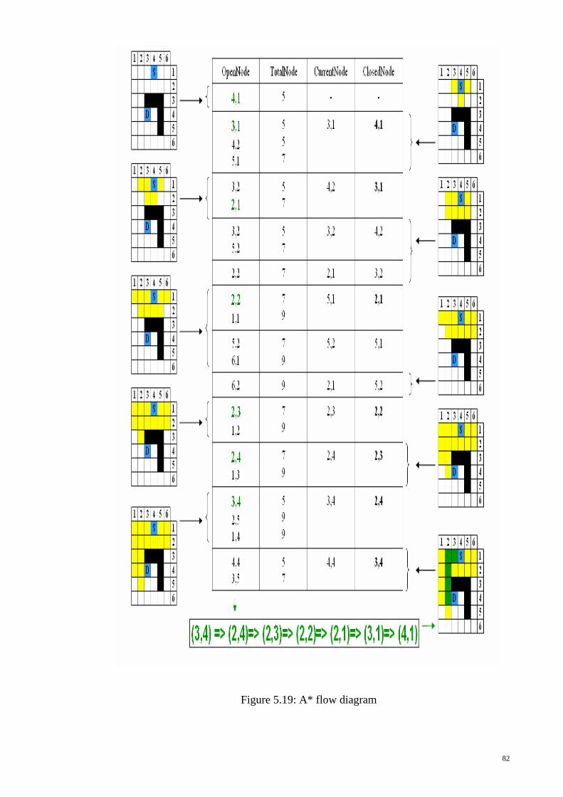
82
Figure 5.19: A* flow diagram
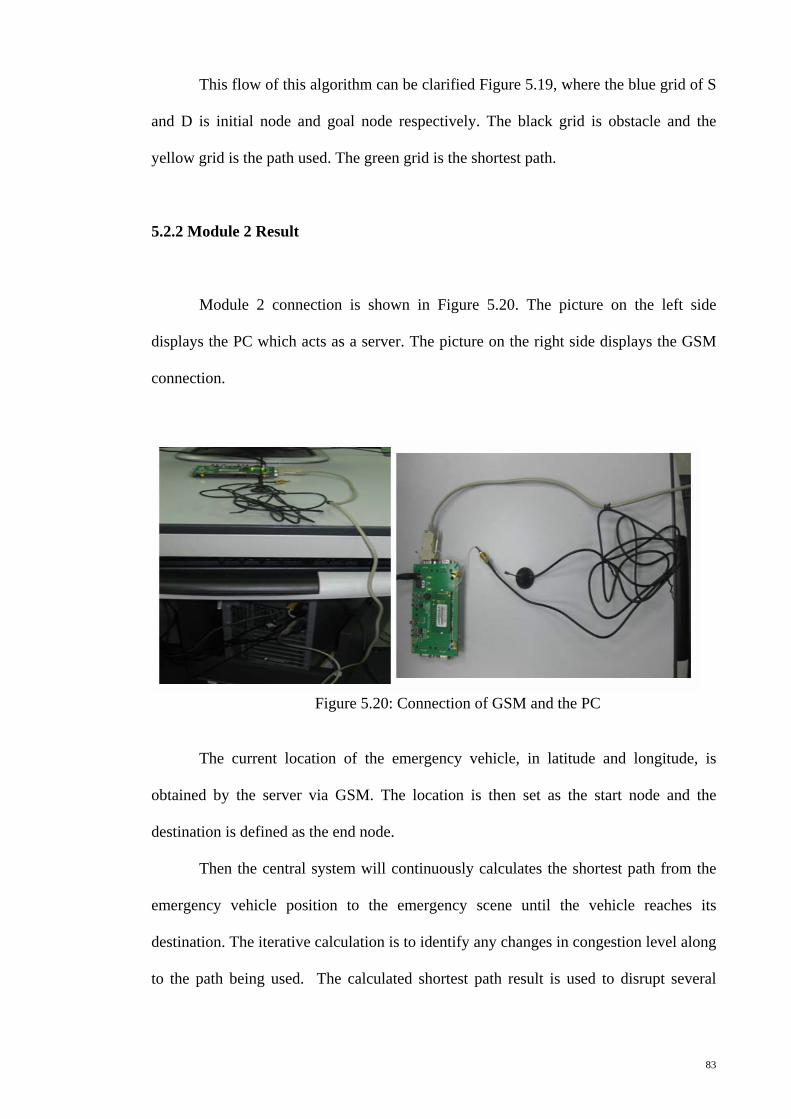
This flow of this algorithm can be clarified Figure 5.19, where the blue grid of S
and D is initial node and goal node respectively. The black grid is obstacle and the
yellow grid is the path used. The green grid is the shortest path.
5.2.2 Module 2 Result
Module 2 connection is shown in Figure 5.20. The picture on the left side
displays the PC which acts as a server. The picture on the right side displays the GSM
connection.
Figure 5.20: Connection of GSM and the PC
The current location of the emergency vehicle, in latitude and longitude, is
obtained by the server via GSM. The location is then set as the start node and the
destination is defined as the end node.
Then the central system will continuously calculates the shortest path from the
emergency vehicle position to the emergency scene until the vehicle reaches its
destination. The iterative calculation is to identify any changes in congestion level along
to the path being used. The calculated shortest path result is used to disrupt several
83
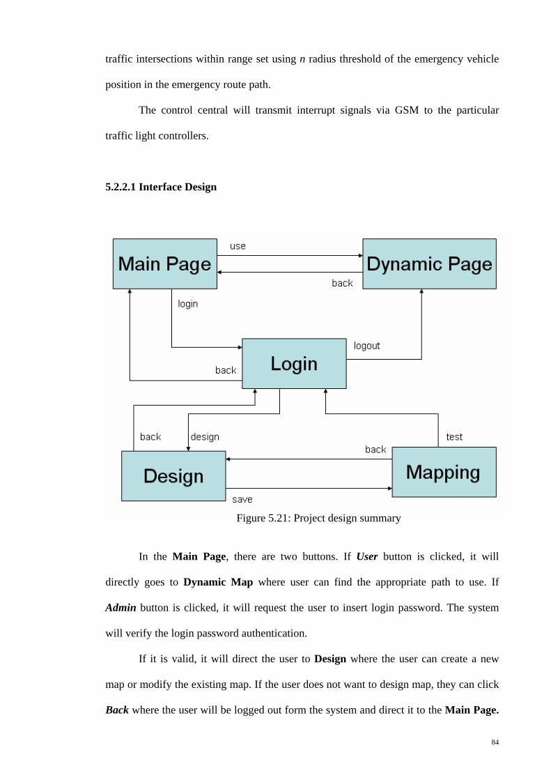
traffic intersections within range set using n radius threshold of the emergency vehicle
position in the emergency route path.
The control central will transmit interrupt signals via GSM to the particular
traffic light controllers.
5.2.2.1 Interface Design
Figure 5.21: Project design summary
In the Main Page, there are two buttons. If User button is clicked, it will
directly goes to Dynamic Map where user can find the appropriate path to use. If
Admin button is clicked, it will request the user to insert login password. The system
will verify the login password authentication.
If it is valid, it will direct the user to Design where the user can create a new
map or modify the existing map. If the user does not want to design map, they can click
Back where the user will be logged out form the system and direct it to the Main Page.
84
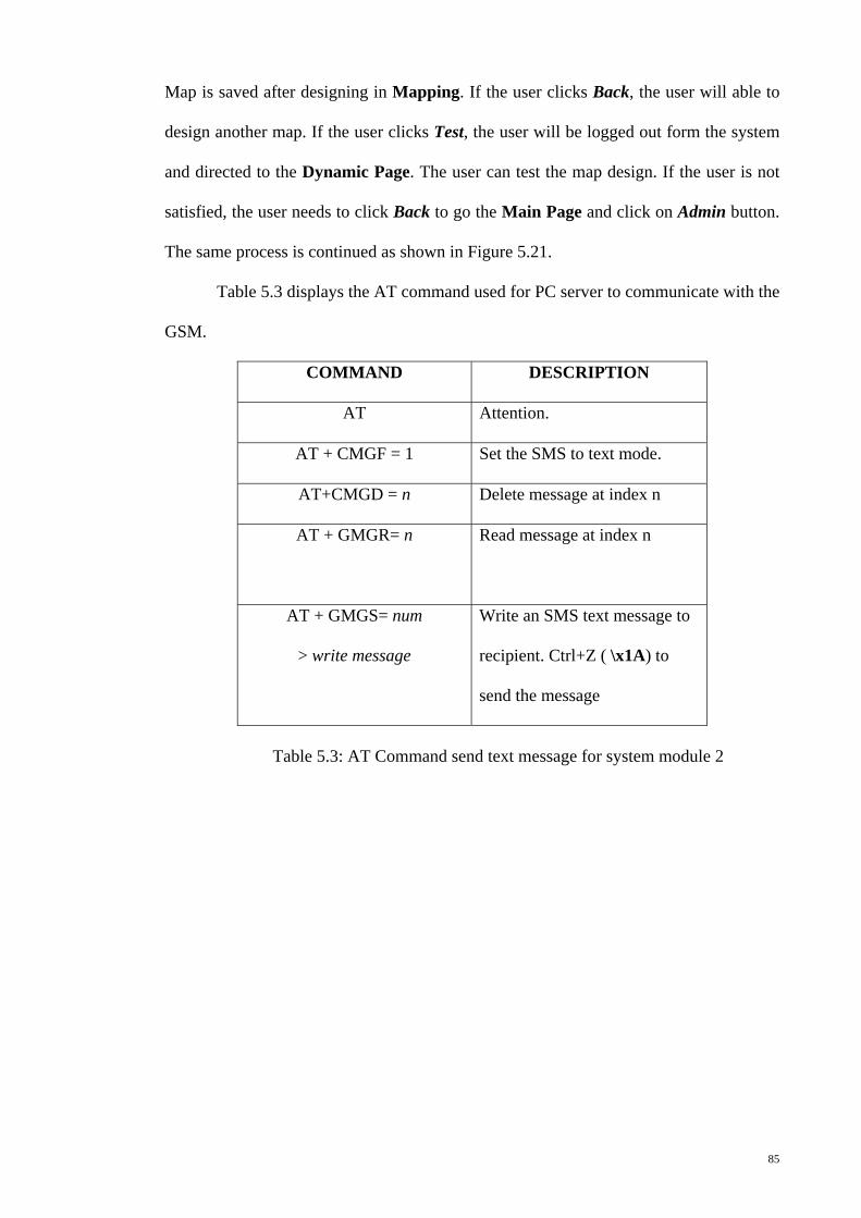
Map is saved after designing in Mapping. If the user clicks Back, the user will able to
design another map. If the user clicks Test, the user will be logged out form the system
and directed to the Dynamic Page. The user can test the map design. If the user is not
satisfied, the user needs to click Back to go the Main Page and click on Admin button.
The same process is continued as shown in Figure 5.21.
Table 5.3 displays the AT command used for PC server to communicate with the
GSM.
COMMAND DESCRIPTION
AT Attention.
AT + CMGF = 1 Set the SMS to text mode.
AT+CMGD = n Delete message at index n
AT + GMGR= n
Read message at index n
AT + GMGS= num
> write message
Write an SMS text message to
recipient. Ctrl+Z ( \x1A) to
send the message
Table 5.3: AT Command send text message for system module 2
85
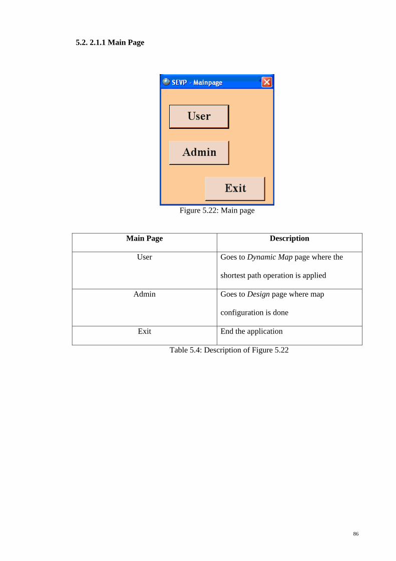
5.2. 2.1.1 Main Page
Figure 5.22: Main page
Main Page Description
User Goes to Dynamic Map page where the
shortest path operation is applied
Admin Goes to Design page where map
configuration is done
Exit End the application
Table 5.4: Description of Figure 5.22
86
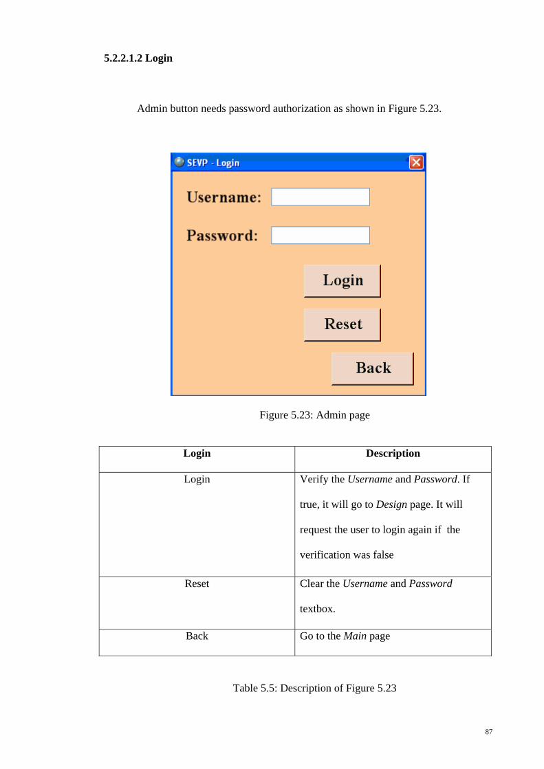
5.2.2.1.2 Login
Admin button needs password authorization as shown in Figure 5.23.
Figure 5.23: Admin page
Login Description
Login Verify the Username and Password. If
true, it will go to Design page. It will
request the user to login again if the
verification was false
Reset Clear the Username and Password
textbox.
Back Go to the Main page
Table 5.5: Description of Figure 5.23
87
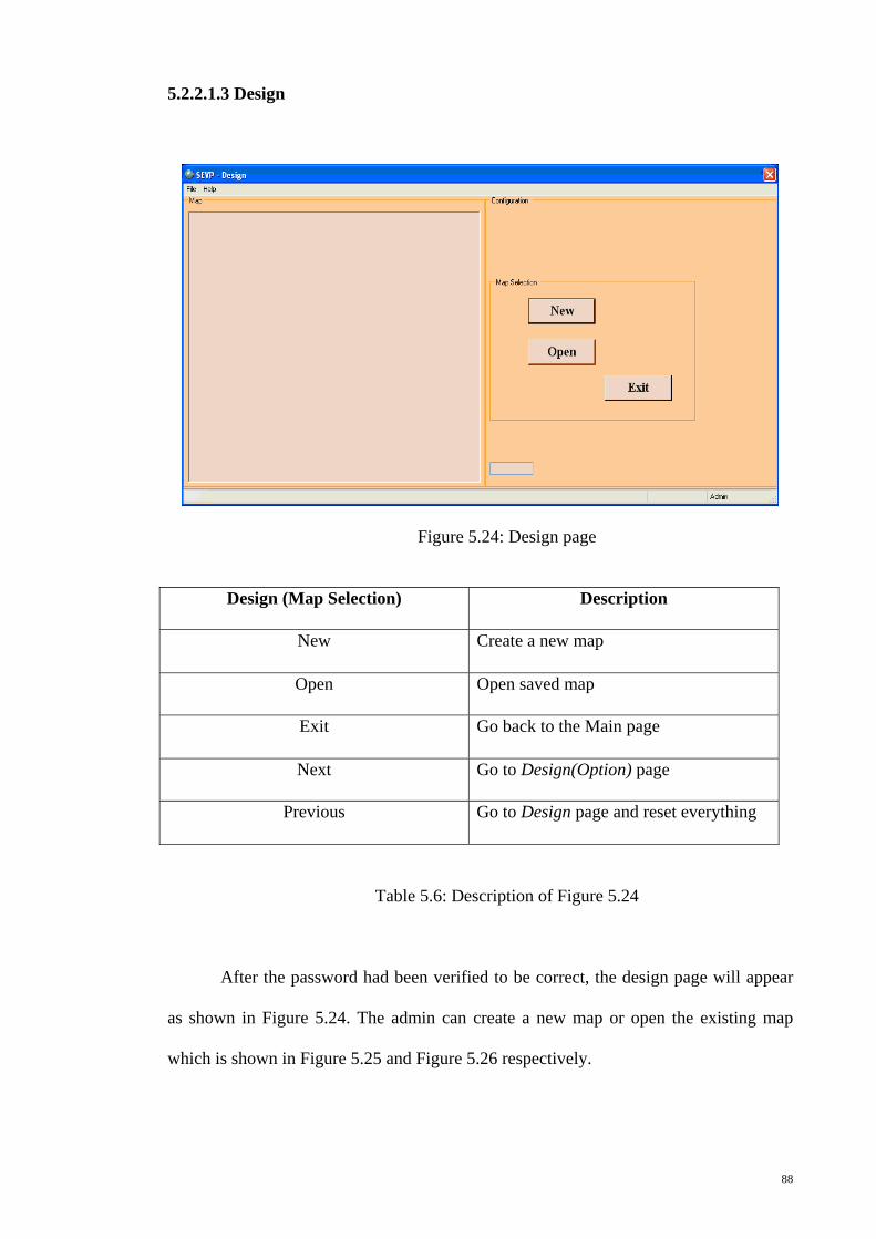
5.2.2.1.3 Design
Figure 5.24: Design page
Design (Map Selection) Description
New Create a new map
Open Open saved map
Exit Go back to the Main page
Next Go to Design(Option) page
Previous Go to Design page and reset everything
Table 5.6: Description of Figure 5.24
After the password had been verified to be correct, the design page will appear
as shown in Figure 5.24. The admin can create a new map or open the existing map
which is shown in Figure 5.25 and Figure 5.26 respectively.
88
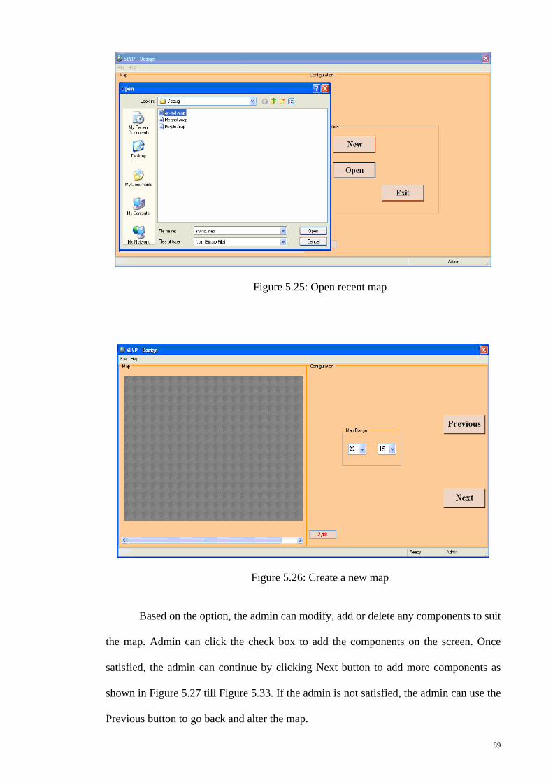
Figure 5.25: Open recent map
Figure 5.26: Create a new map
Based on the option, the admin can modify, add or delete any components to suit
the map. Admin can click the check box to add the components on the screen. Once
satisfied, the admin can continue by clicking Next button to add more components as
shown in Figure 5.27 till Figure 5.33. If the admin is not satisfied, the admin can use the
Previous button to go back and alter the map.
89
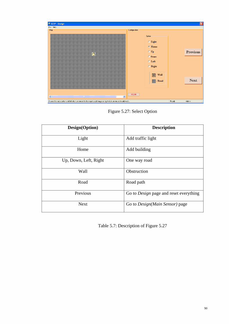
Figure 5.27: Select Option
Design(Option) Description
Light Add traffic light
Home Add building
Up, Down, Left, Right One way road
Wall Obstruction
Road Road path
Previous Go to Design page and reset everything
Next Go to Design(Main Sensor) page
Table 5.7: Description of Figure 5.27
90
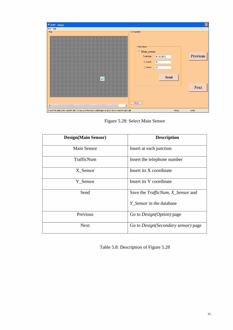
Figure 5.28: Select Main Sensor
Design(Main Sensor) Description
Main Sensor Insert at each junction
TrafficNum Insert the telephone number
X_Sensor Insert its X coordinate
Y_Sensor Insert its Y coordinate
Send Save the TrafficNum, X_Sensor and
Y_Sensor in the database
Previous Go to Design(Option) page
Next Go to Design(Secondary sensor) page
Table 5.8: Description of Figure 5.28
91
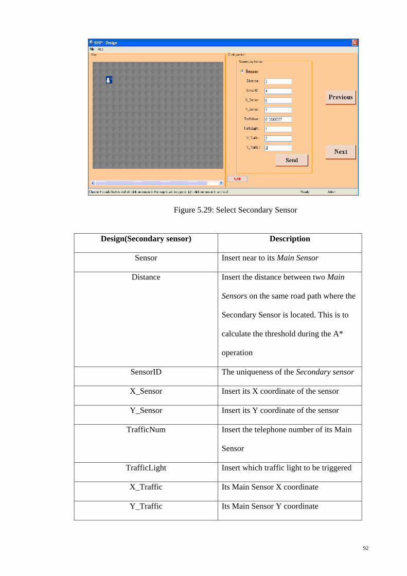
Figure 5.29: Select Secondary Sensor
Design(Secondary sensor) Description
Sensor Insert near to its Main Sensor
Distance Insert the distance between two Main
Sensors on the same road path where the
Secondary Sensor is located. This is to
calculate the threshold during the A*
operation
SensorID The uniqueness of the Secondary sensor
X_Sensor Insert its X coordinate of the sensor
Y_Sensor Insert its Y coordinate of the sensor
TrafficNum Insert the telephone number of its Main
Sensor
TrafficLight Insert which traffic light to be triggered
X_Traffic Its Main Sensor X coordinate
Y_Traffic Its Main Sensor Y coordinate
92
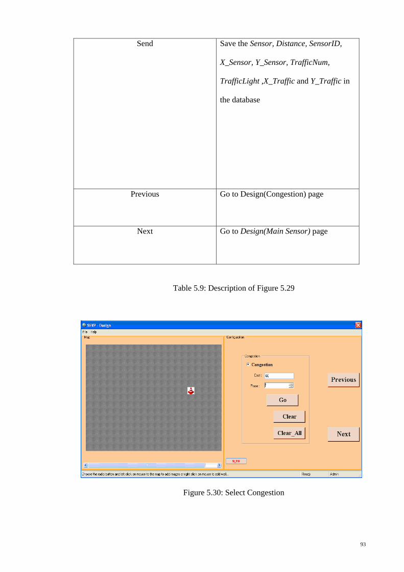
Send Save the Sensor, Distance, SensorID,
X_Sensor, Y_Sensor, TrafficNum,
TrafficLight ,X_Traffic and Y_Traffic in
the database
Previous Go to Design(Congestion) page
Next Go to Design(Main Sensor) page
Table 5.9: Description of Figure 5.29
Figure 5.30: Select Congestion
93
Design(Congestion) Description
Congestion Insert congestion on the road or junction
Cost Insert how heavy is the road traffic
congestion
Place The uniqueness of the Congestion
Go Spot the Congestion based on its Place
number
Clear Remove the Congestion based its Place
number
Clear_All Remove all the Congestion
Previous Go to Design(Secondary sensor) page
Next Save the map in Mapping page
Table 5.10: Description of Figure 5.30
94
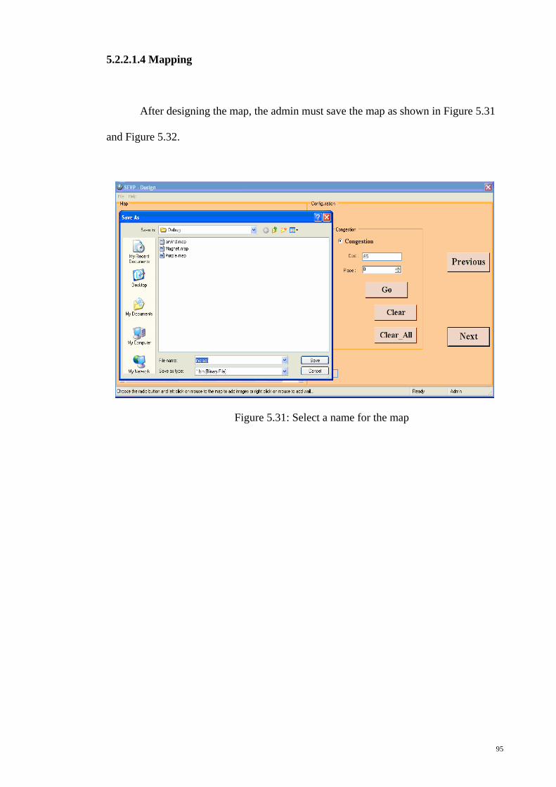
5.2.2.1.4 Mapping
After designing the map, the admin must save the map as shown in Figure 5.31
and Figure 5.32.
Figure 5.31: Select a name for the map
95

Figure 5.32: Insert the location for the map
Mapping Description
Save Save the map particulars in the database
Reset Rewrite the particulars
Test Go to Dynamic Map page to analyze the
map
Table 5.11: Description of Figure 5.32
5.2.2.1.5 Dynamic Map
Then, the admin can test the design in USER page as shown in Figure 5.33. Start
x,y will automatically display the location of the emergency vehicle once the vehicle
switch on the tracking device. After the destination location is inserted, the Send button
is clicked. The system will guide the emergency vehicle providing shortest path route
using dead-reckoning techniques. GSM information is displayed in the Status box.
96
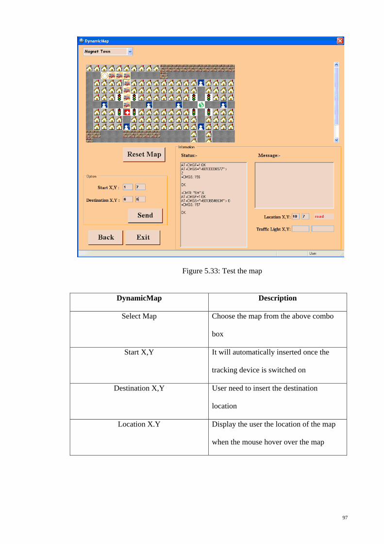
Figure 5.33: Test the map
DynamicMap Description
Select Map Choose the map from the above combo
box
Start X,Y It will automatically inserted once the
tracking device is switched on
Destination X,Y User need to insert the destination
location
Location X.Y Display the user the location of the map
when the mouse hover over the map
97
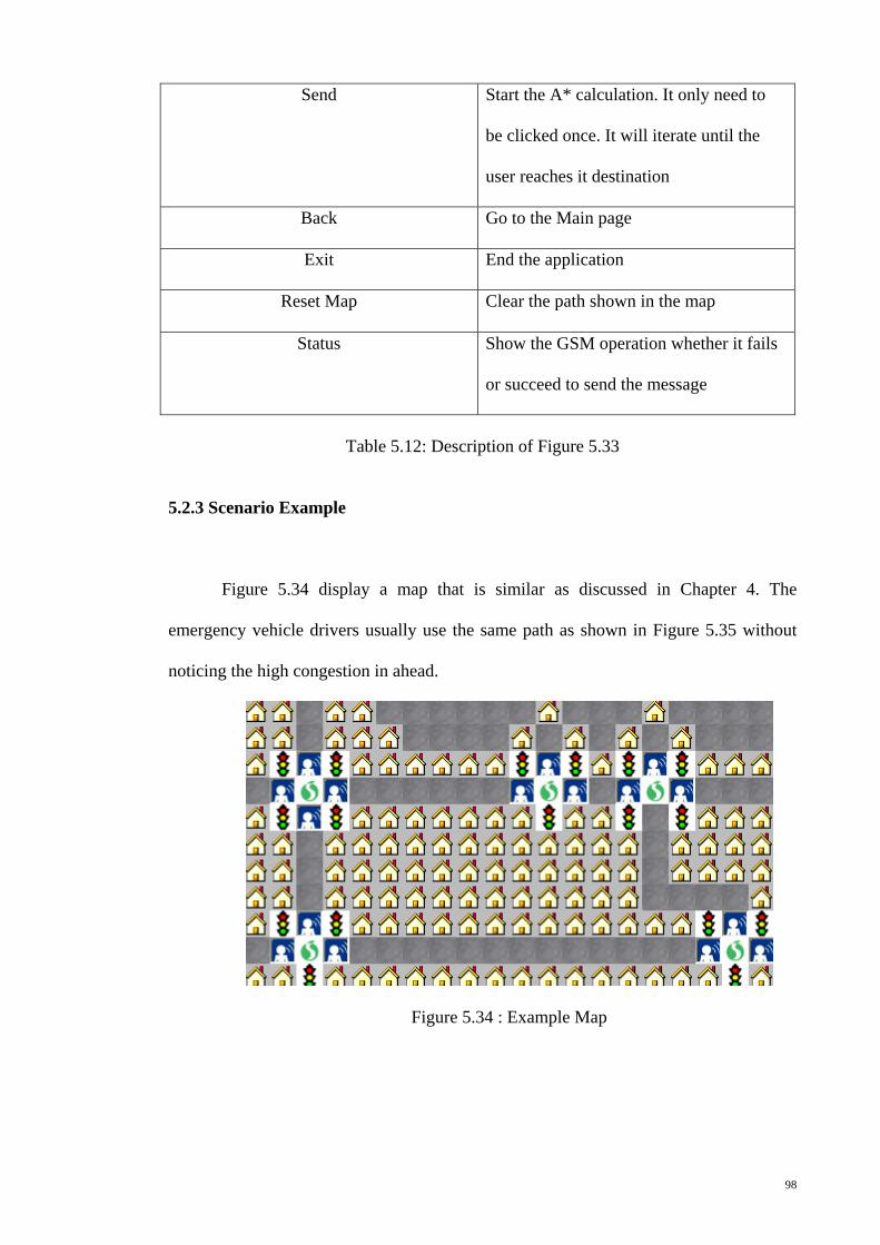
Send Start the A* calculation. It only need to
be clicked once. It will iterate until the
user reaches it destination
Back Go to the Main page
Exit End the application
Reset Map Clear the path shown in the map
Status Show the GSM operation whether it fails
or succeed to send the message
Table 5.12: Description of Figure 5.33
5.2.3 Scenario Example
Figure 5.34 display a map that is similar as discussed in Chapter 4. The
emergency vehicle drivers usually use the same path as shown in Figure 5.35 without
noticing the high congestion in ahead.
Figure 5.34 : Example Map
98
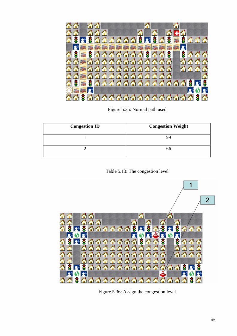
Figure 5.35: Normal path used
Congestion ID Congestion Weight
1 99
2 66
Table 5.13: The congestion level
Figure 5.36: Assign the congestion level
99
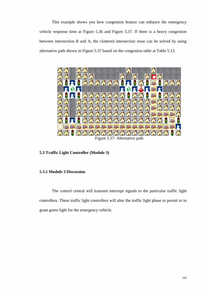
This example shows you how congestion feature can enhance the emergency
vehicle response time at Figure 5.36 and Figure 5.37. If there is a heavy congestion
between intersection B and A, the cluttered intersection issue can be solved by using
alternative path shown in Figure 5.37 based on the congestion table at Table 5.13.
Figure 5.37: Alternative path
5.3 Traffic Light Controller (Module 3)
5.3.1 Module 3 Discussion
The control central will transmit interrupt signals to the particular traffic light
controllers. These traffic light controllers will alter the traffic light phase to permit or to
grant green light for the emergency vehicle.
100
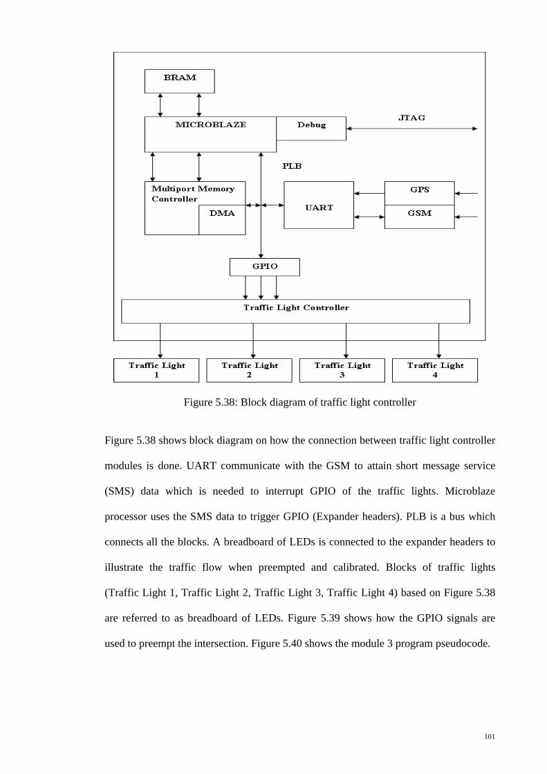
Figure 5.38: Block diagram of traffic light controller
Figure 5.38 shows block diagram on how the connection between traffic light controller
modules is done. UART communicate with the GSM to attain short message service
(SMS) data which is needed to interrupt GPIO of the traffic lights. Microblaze
processor uses the SMS data to trigger GPIO (Expander headers). PLB is a bus which
connects all the blocks. A breadboard of LEDs is connected to the expander headers to
illustrate the traffic flow when preempted and calibrated. Blocks of traffic lights
(Traffic Light 1, Traffic Light 2, Traffic Light 3, Traffic Light 4) based on Figure 5.38
are referred to as breadboard of LEDs. Figure 5.39 shows how the GPIO signals are
used to preempt the intersection. Figure 5.40 shows the module 3 program pseudocode.
101
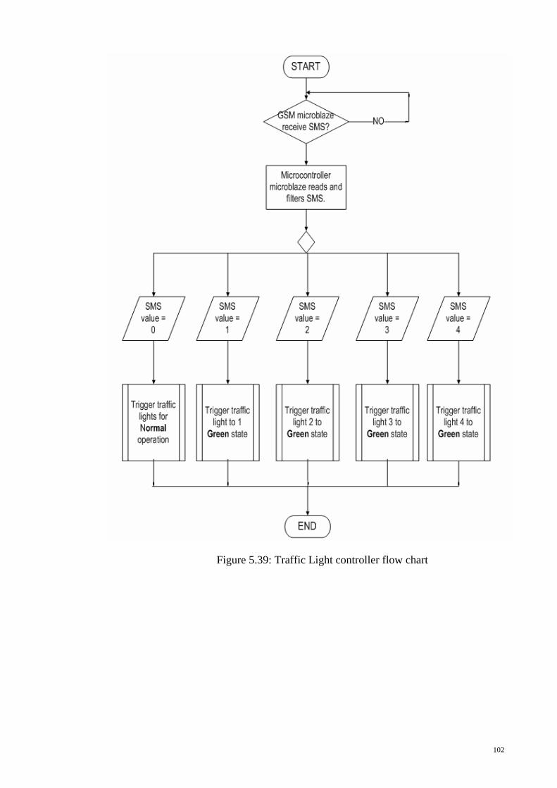
Figure 5.39: Traffic Light controller flow chart
102
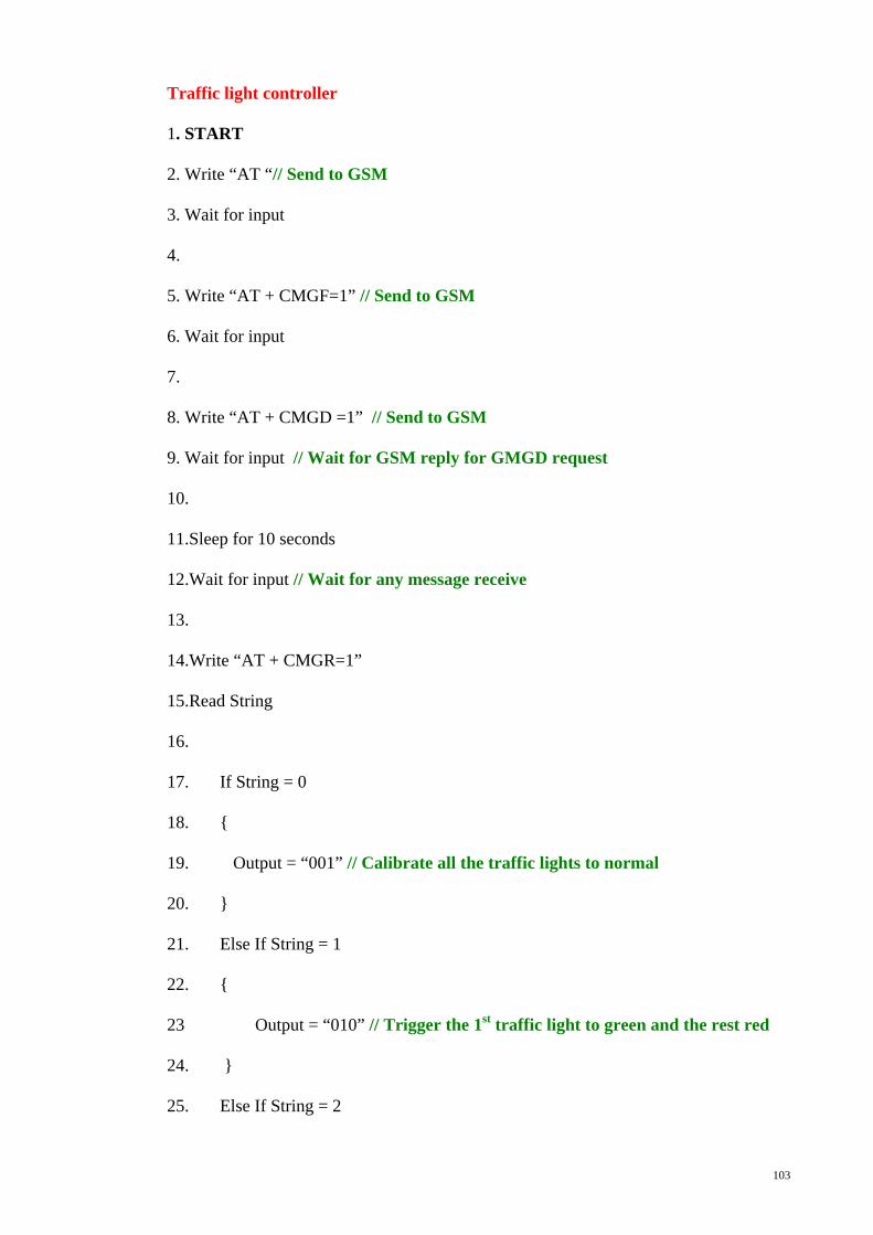
Traffic light controller
1. START
2. Write “AT “// Send to GSM
3. Wait for input
4.
5. Write “AT + CMGF=1” // Send to GSM
6. Wait for input
7.
8. Write “AT + CMGD =1” // Send to GSM
9. Wait for input // Wait for GSM reply for GMGD request
10.
11.Sleep for 10 seconds
12.Wait for input // Wait for any message receive
13.
14.Write “AT + CMGR=1”
15.Read String
16.
17. If String = 0
18. {
19. Output = “001” // Calibrate all the traffic lights to normal
20. }
21. Else If String = 1
22. {
23 Output = “010” // Trigger the 1st traffic light to green and the rest red
24. }
25. Else If String = 2
103
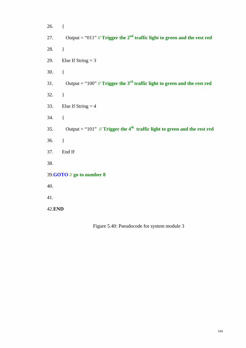
26. {
27. Output = “011” // Trigger the 2nd traffic light to green and the rest red
28. }
29. Else If String = 3
30. {
31. Output = “100” // Trigger the 3rd traffic light to green and the rest red
32. }
33. Else If String = 4
34. {
35. Output = “101” // Trigger the 4th traffic light to green and the rest red
36. }
37. End If
38.
39.GOTO // go to number 8
40.
41.
42.END
Figure 5.40: Pseudocode for system module 3
104
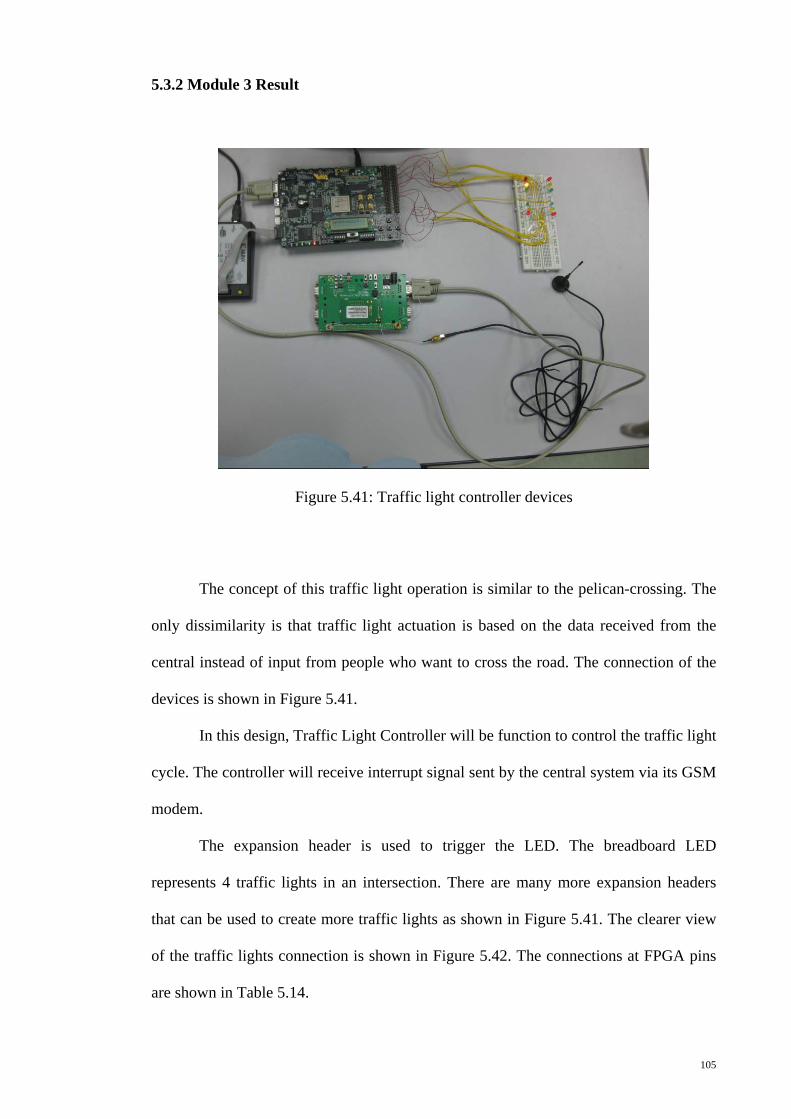
5.3.2 Module 3 Result
Figure 5.41: Traffic light controller devices
The concept of this traffic light operation is similar to the pelican-crossing. The
only dissimilarity is that traffic light actuation is based on the data received from the
central instead of input from people who want to cross the road. The connection of the
devices is shown in Figure 5.41.
In this design, Traffic Light Controller will be function to control the traffic light
cycle. The controller will receive interrupt signal sent by the central system via its GSM
modem.
The expansion header is used to trigger the LED. The breadboard LED
represents 4 traffic lights in an intersection. There are many more expansion headers
that can be used to create more traffic lights as shown in Figure 5.41. The clearer view
of the traffic lights connection is shown in Figure 5.42. The connections at FPGA pins
are shown in Table 5.14.
105
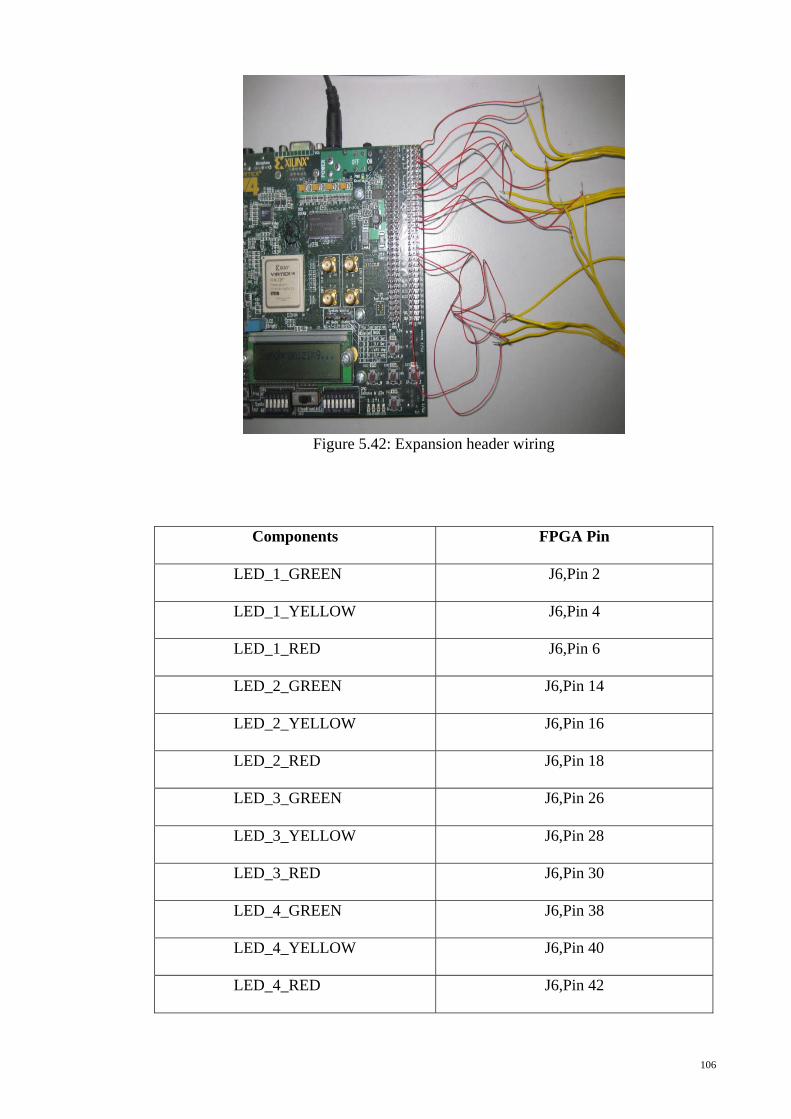
Figure 5.42: Expansion header wiring
Components FPGA Pin
LED_1_GREEN J6,Pin 2
LED_1_YELLOW J6,Pin 4
LED_1_RED J6,Pin 6
LED_2_GREEN J6,Pin 14
LED_2_YELLOW J6,Pin 16
LED_2_RED J6,Pin 18
LED_3_GREEN J6,Pin 26
LED_3_YELLOW J6,Pin 28
LED_3_RED J6,Pin 30
LED_4_GREEN J6,Pin 38
LED_4_YELLOW J6,Pin 40
LED_4_RED J6,Pin 42
106
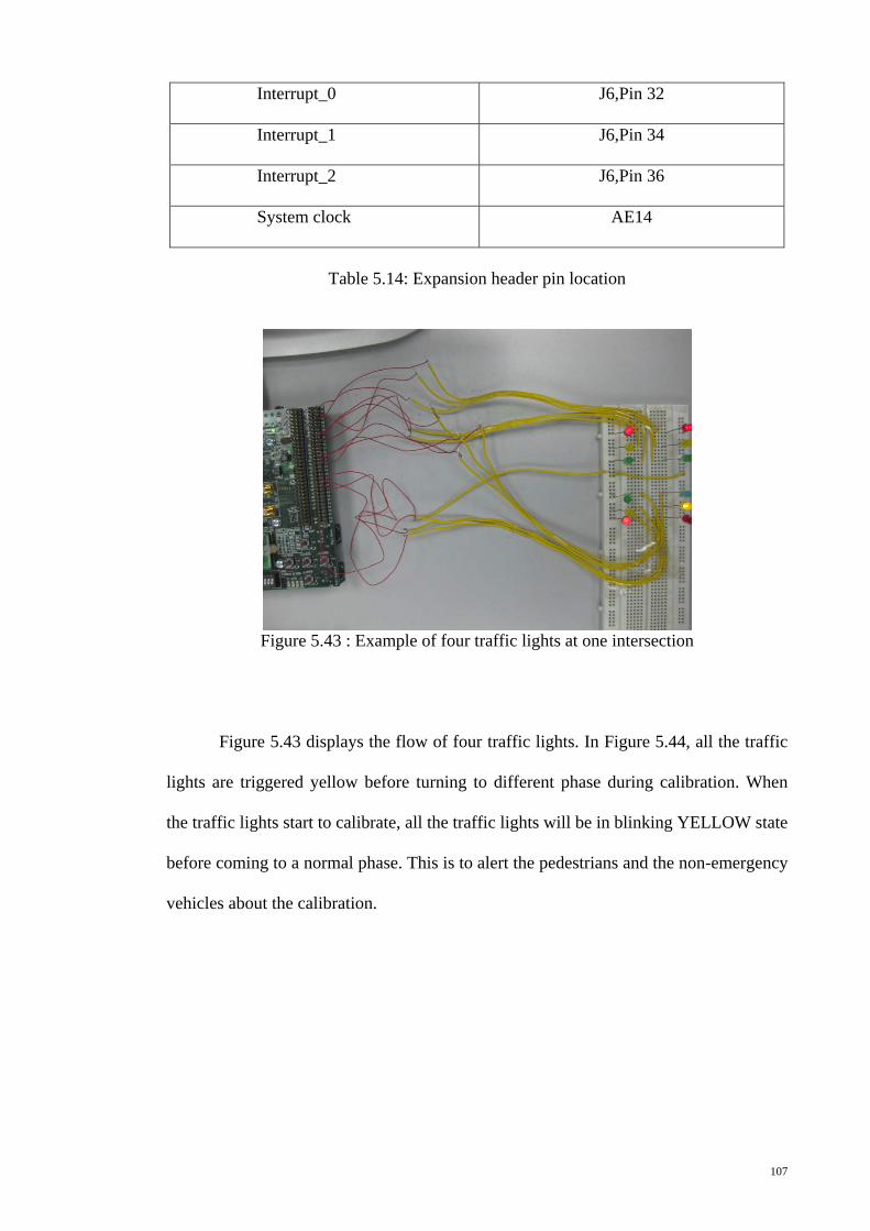
Interrupt_0 J6,Pin 32
Interrupt_1 J6,Pin 34
Interrupt_2 J6,Pin 36
System clock AE14
Table 5.14: Expansion header pin location
Figure 5.43 : Example of four traffic lights at one intersection
Figure 5.43 displays the flow of four traffic lights. In Figure 5.44, all the traffic
lights are triggered yellow before turning to different phase during calibration. When
the traffic lights start to calibrate, all the traffic lights will be in blinking YELLOW state
before coming to a normal phase. This is to alert the pedestrians and the non-emergency
vehicles about the calibration.
107
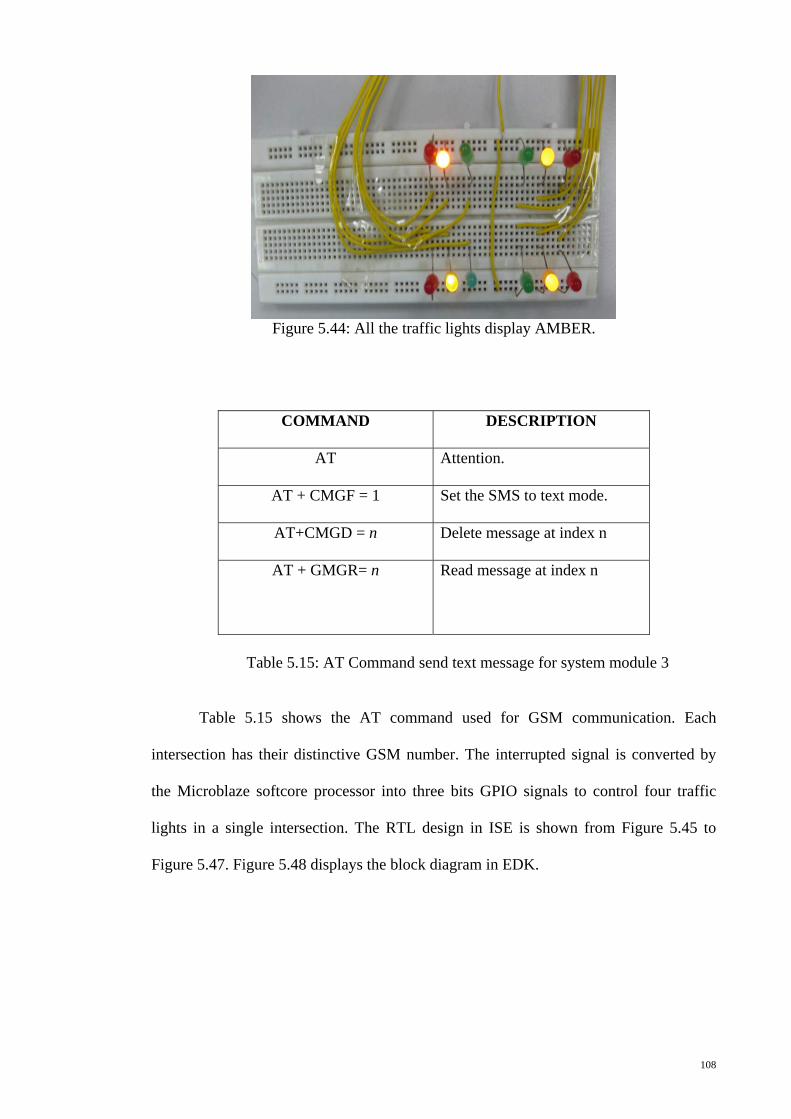
Figure 5.44: All the traffic lights display AMBER.
COMMAND DESCRIPTION
AT Attention.
AT + CMGF = 1 Set the SMS to text mode.
AT+CMGD = n Delete message at index n
AT + GMGR= n
Read message at index n
Table 5.15: AT Command send text message for system module 3
Table 5.15 shows the AT command used for GSM communication. Each
intersection has their distinctive GSM number. The interrupted signal is converted by
the Microblaze softcore processor into three bits GPIO signals to control four traffic
lights in a single intersection. The RTL design in ISE is shown from Figure 5.45 to
Figure 5.47. Figure 5.48 displays the block diagram in EDK.
108
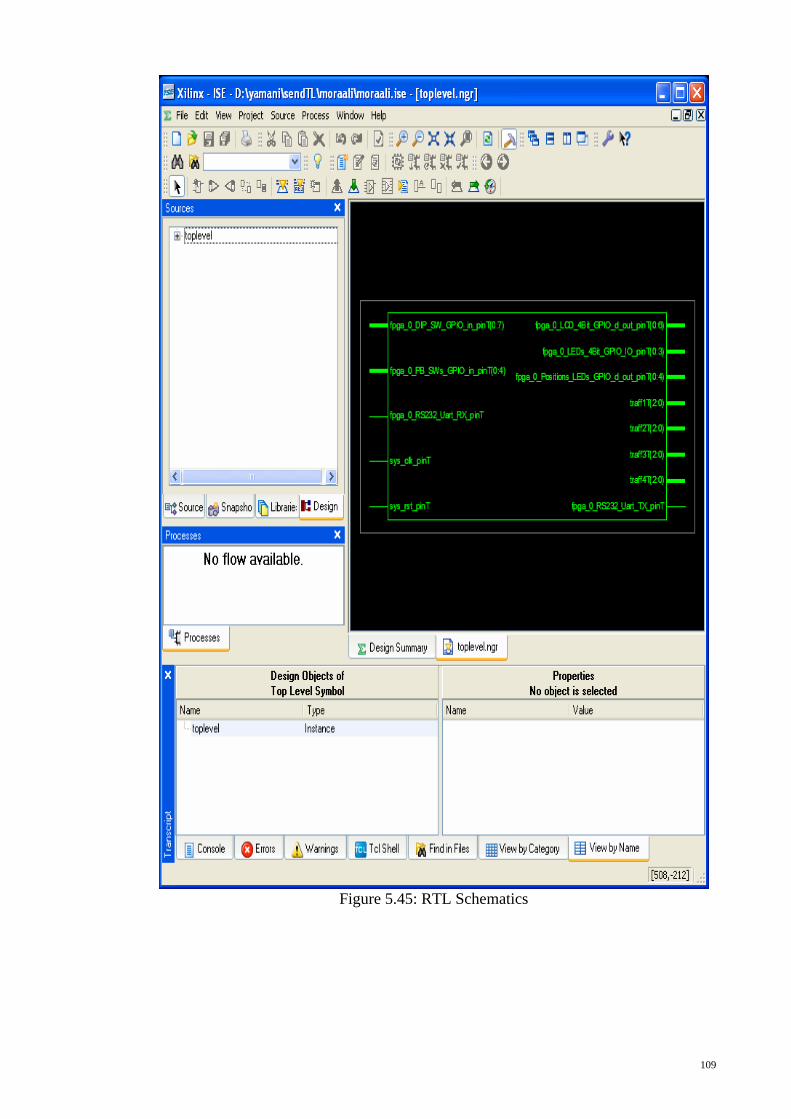
Figure 5.45: RTL Schematics
109
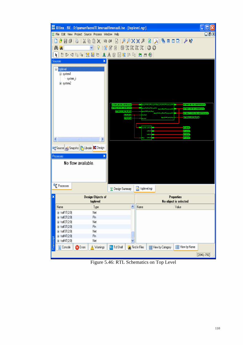
Figure 5.46: RTL Schematics on Top Level
110
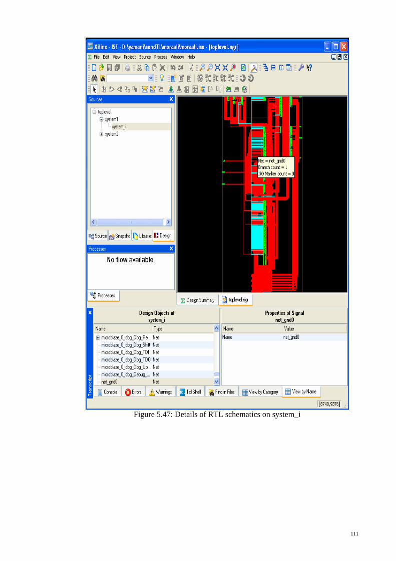
Figure 5.47: Details of RTL schematics on system_i
111
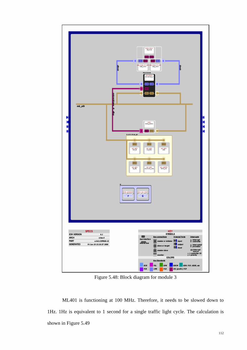
Figure 5.48: Block diagram for module 3
ML401 is functioning at 100 MHz. Therefore, it needs to be slowed down to
1Hz. 1Hz is equivalent to 1 second for a single traffic light cycle. The calculation is
shown in Figure 5.49
112
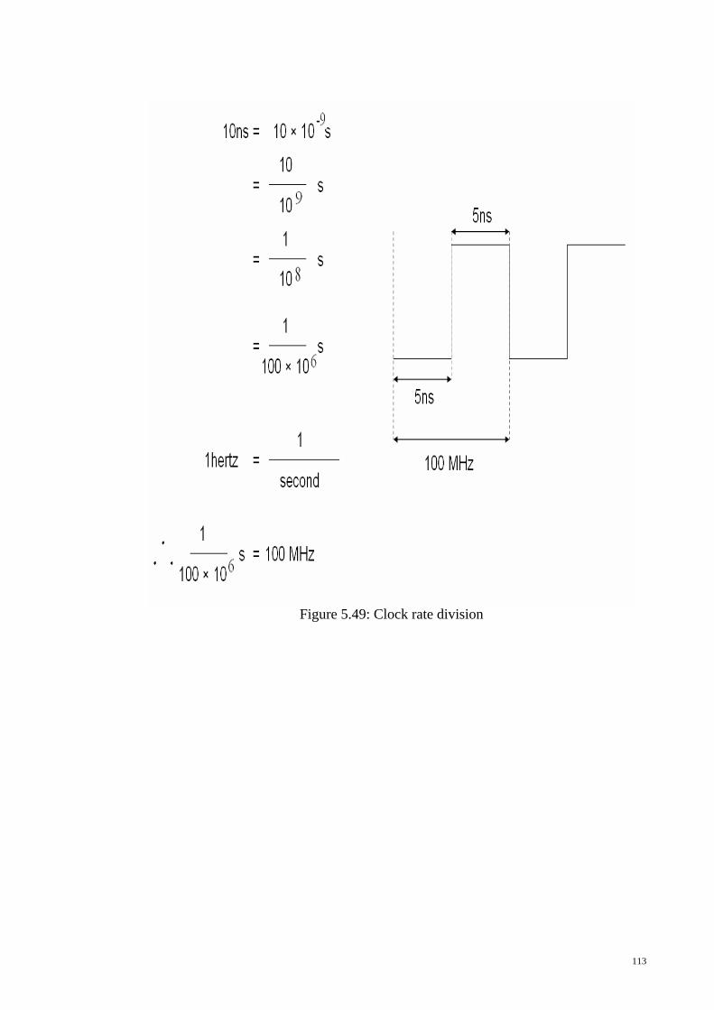
Figure 5.49: Clock rate division
113
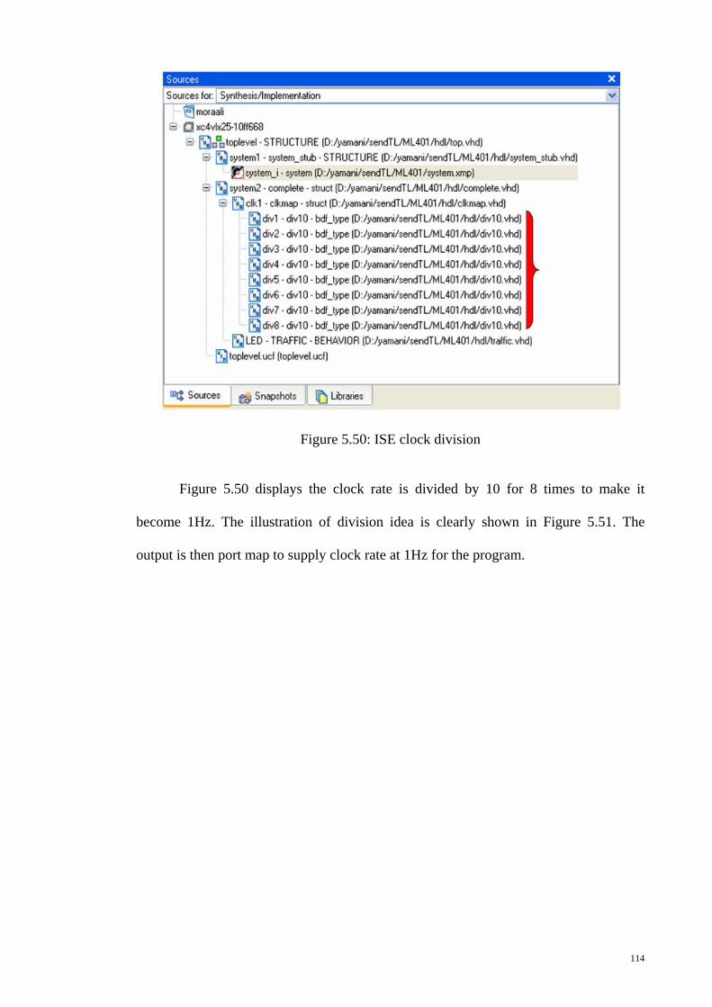
Figure 5.50: ISE clock division
Figure 5.50 displays the clock rate is divided by 10 for 8 times to make it
become 1Hz. The illustration of division idea is clearly shown in Figure 5.51. The
output is then port map to supply clock rate at 1Hz for the program.
114
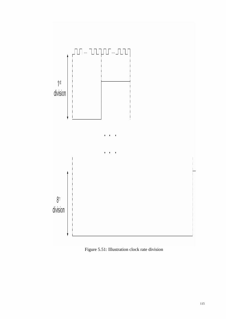
Figure 5.51: Illustration clock rate division
115
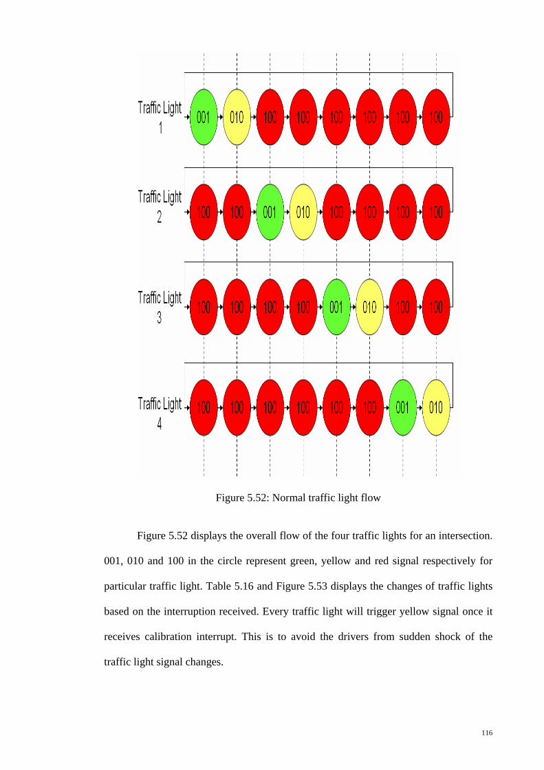
Figure 5.52: Normal traffic light flow
Figure 5.52 displays the overall flow of the four traffic lights for an intersection.
001, 010 and 100 in the circle represent green, yellow and red signal respectively for
particular traffic light. Table 5.16 and Figure 5.53 displays the changes of traffic lights
based on the interruption received. Every traffic light will trigger yellow signal once it
receives calibration interrupt. This is to avoid the drivers from sudden shock of the
traffic light signal changes.
116
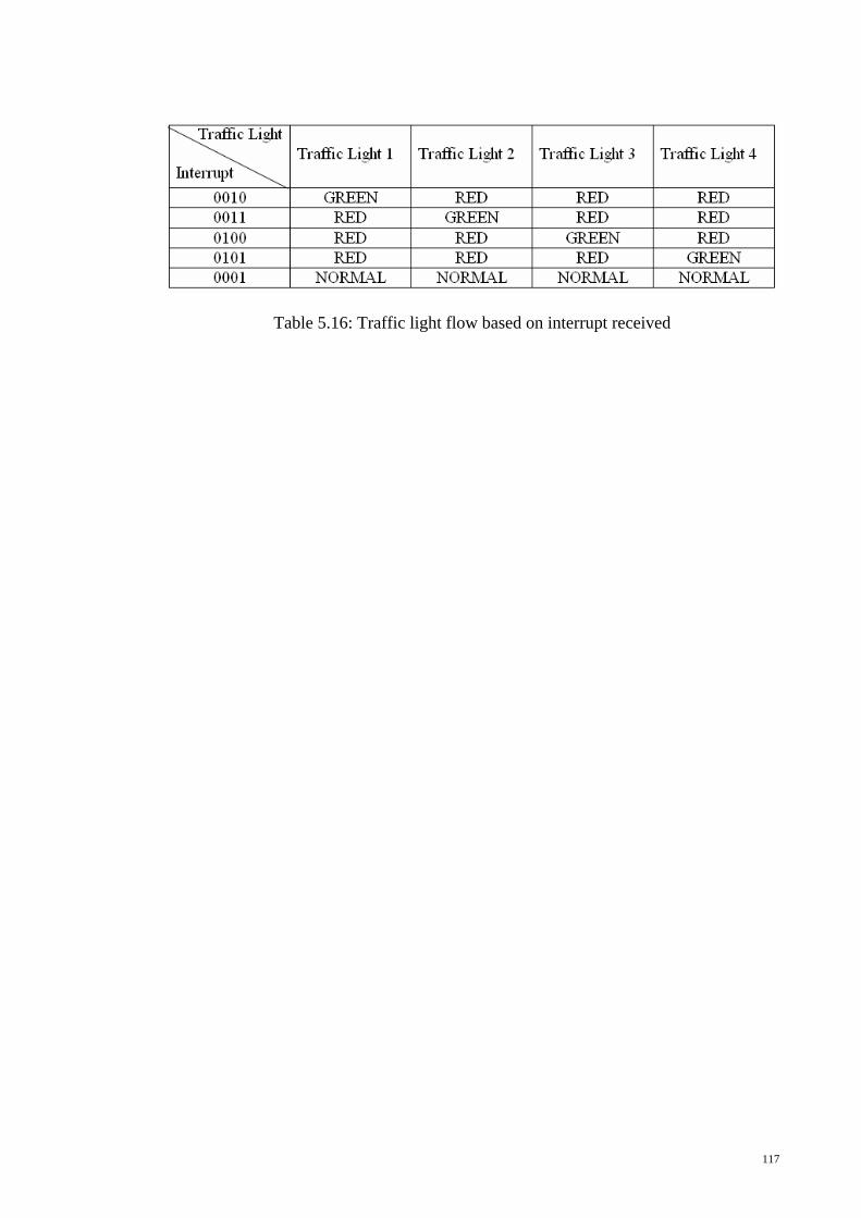
Table 5.16: Traffic light flow based on interrupt received
117
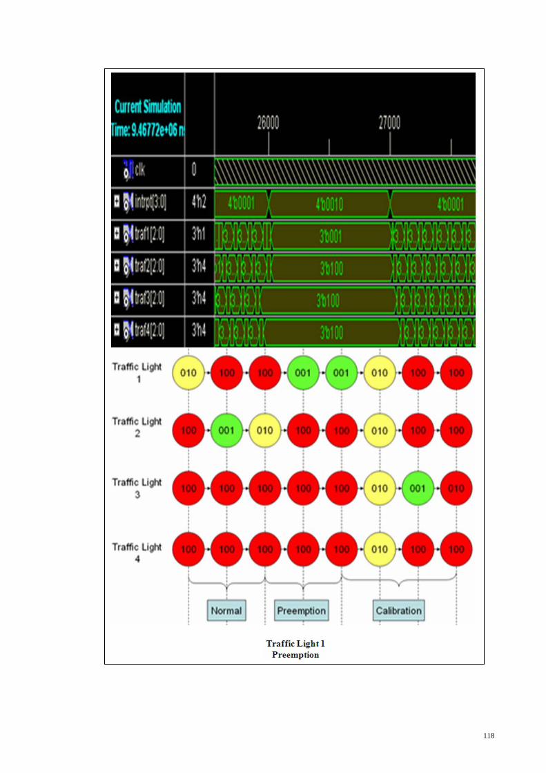
118
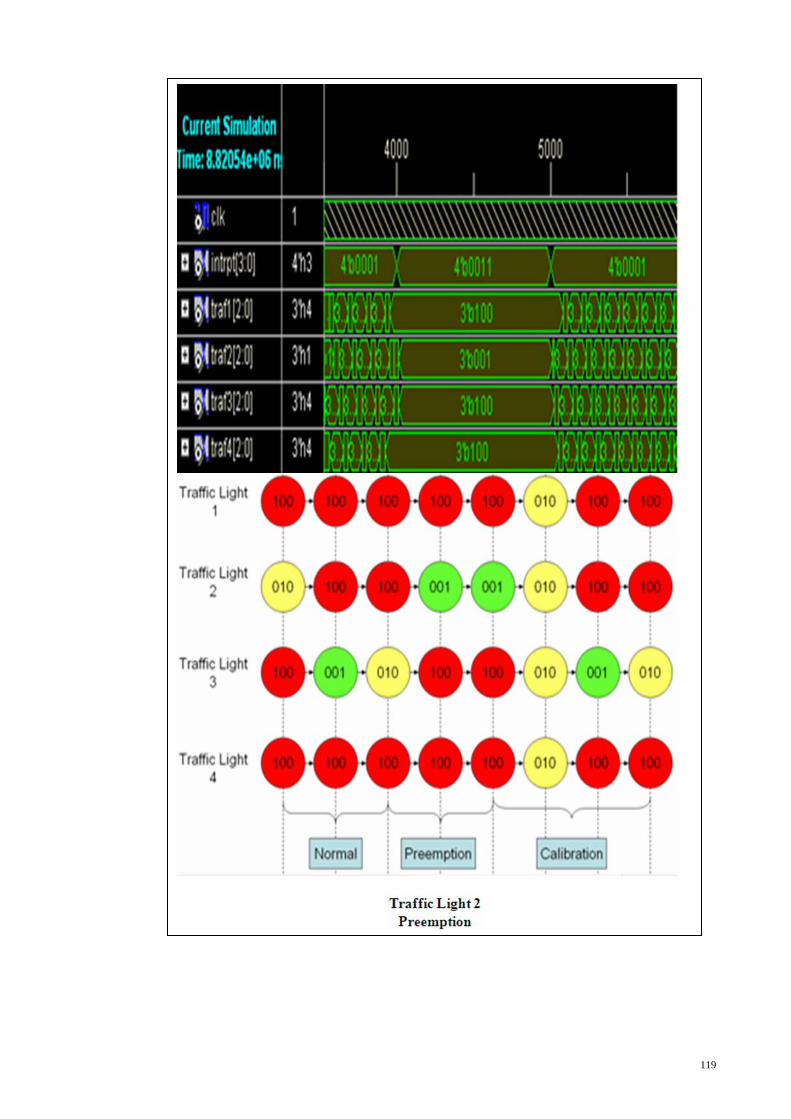
119
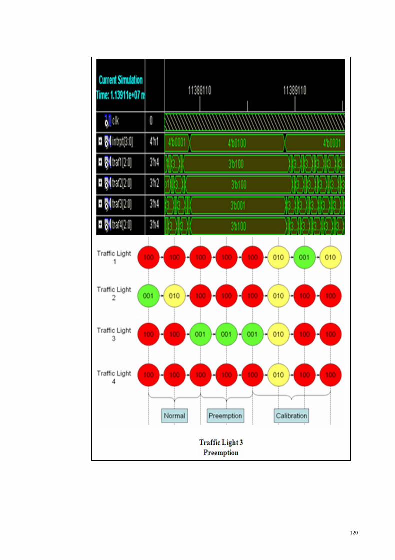
120
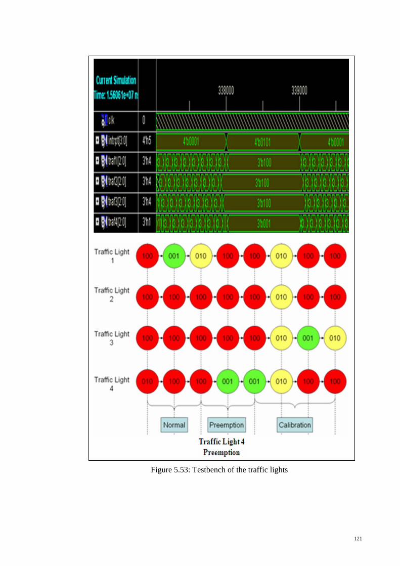
Figure 5.53: Testbench of the traffic lights
121
5.4 Conclusion
The implementation process of the SEVP is explained in this chapter. The SEVP
process is explained in each module in order to provide a vivid understanding of the
system. Module 1 and module 3 of the system is focused on hardware aspect. Module 2
provides clarification on the software feature. Chapter 4 intersection site is taken as a
case example to demonstrate how SEVP capable to solve cluttered intersection problem
and alternative route problem.
.
122
Chapter 6 Conclusion
Emergency Vehicle Preemption (EVP) is a system that intervenes in the normal
operation of traffic control systems to grant emergency vehicles to pass through. In this
thesis, conventional EVP is studied in order to identify their problems and room for
improvements. Based on the information collected, three main problems are identified.
The first problem is related to short range signal (e.g. light, sound or radio wave signals)
utilized in the conventional system. The short range signal has the drawback to only
trigger one traffic light intersection at a time. The inability to preempt more than one
traffic light intersections will lead to cluttered intersection problem where red
intersections ahead will halt the emergency vehicle from passing through the green pre-
empted intersection. The following problem is classified as the lane preemption
problem. In the conventional system, the emergency vehicle must use exact lane to
trigger the intersection ahead. The exact lane has to be chosen since the sensor is
located at each lane. To trigger the left traffic light which leads to the left path for
instance, the emergency vehicle must use the left lane. This restriction is not suitable in
emergency cases since emergency personnel will generally decide on a faster lane. The
third problem is classified as alternative route problem where in this class, conventional
EVP does not provide a clear navigation of alternative path that consume less time. All
the problems are verified using data collection method in the earlier chapter.
Smart Emergency Vehicle Preemption system (SEVP) is proposed to overcome
the drawbacks of short range signal difficulty, incorrect lane problem and alternative
route quandary. The system grants green lights to more than one intersection within the
distance or threshold set. Positioning technique and A-star (A*) shortest path algorithm
is used in the proposed system to permit the system to control and to calibrate road
traffic light systems using wireless communications installed on emergency vehicles
123
and traffic intersections. The SEVP is divided into three modules where the first module
focuses on tracking the emergency vehicle. FPGA embedded with Xilinx Microblaze
soft processor core and SIM 508 GPS/GSM modem is installed on the emergency
vehicle for tracking purpose. The FPGA will filter unnecessary GPS data to get the
current latitude and longitude of the emergency vehicle. Then, the filtered data is
transmitted to the central control via GSM modem. In the second module, the central
control will receive the current position of the emergency vehicle as well as the location
of the emergency scene and then process the A* algorithm to obtain shortest path route
to the destination. The centre will send interrupt command to traffic controllers within
the selected route and distance threshold set to clear the cluttered traffic in front.
Modification on the traffic light controller is done in the third module. The intersection
controller will use the interrupt value to trigger the particular traffic light to green and
trigger the other traffic lights at the junction to be red. The controller is then calibrated
to normal mode after the emergency vehicle passed each traffic light intersection.
Testing process is done to verify whether the project system is functioning in a
proper manner or vice versa. Debugging tools in C#.Net is used to ensure the entire
program flow operate correctly for the third module. ISE simulator is used to validate
the hardware part of process and behavior structure in first module and second module
of the system. In addition, computer Hyperterminal interface is employed to check
hardware and PC interfacing.
For future enhancement, the system can be improved by discarding the central
control intervention. Microblaze soft processor core for Xilinx FPGA provides more
flexibility for the system designer to work on processor based system. User designed
hardware module can be interfaced with this soft processor core within the FPGA itself.
The coprocessor interface accelerates complex algorithms by transferring parts or the
wholeness of the computation to a user-designed hardware module. In order to omit the
124
central intervention, all the GPS core, GSM core, and A-star core can be embedded in
one Xilinx FPGA which able to provide appropriate path to the driver and able to
interrupt the traffic light phase.
The system only allocates a calculation of one emergency case at one time.
Future enhancement can be done by implementing calculation on more than one vehicle
at a time. This can perk up the efficiency of the system.
Security aspect is not covered for the design of this system. But for future
enhancement, security can be focus on the SMS aspect. There is a security issue occurs
in this system which involve the interrupt value sent by SMS. If anyone who perceives
the line number of the traffic light’s GSM modem and the value for interruption, he can
triggers the interruption anytime.To avoid from unauthorized use, Xilinx FPGA can be
embedded with encryption technique for security purpose.
125
REFERENCES
Aaron D. Bachelder, C. F. F. (2006a) Cellular-based preemption system Google Patent.
Aaron D. Bachelder, C. F. F. (2006b) Emergency vehicle control system traffic loop
preemption Google Patent. 340/906; 340/907; 340/931; 340/941 ed., California
Institute of Technology.
Aaron D. Bachelder, C. F. F. (2008) Emergency vehicle traffic signal preemption
system Google Patent. 340/906; 340/902; 701/300 ed., California Institute of
Technology.
Abdullah, M. A. B. (2009) Maintenance and operation of traffic lights in Malaysia.
Kuala Lumpur, TYCO Fire And Company.
Ames, M. B. (2006) Methods and system for providing routing assistance to a vehicle.
Google Patent. 701/117; 701/200 ed.
Apitz, P. & Dyer, E. B. (2001 ) System and method for signal light preemption and
vehicle tracking. United States Patent. G08G1/087; G08G1/07; G08G1/07 ed.
United States
Bentrott, D. W., Brown, D., Asbury, J. R. & Schlichtig, R. J. (1999 ) Emergency vehicle
command and control system for traffic signal preemption. United States Patent.
G08G1/087; G08G1/07; G08G1/07 ed. United States Interlog, Inc.
Bonner, E. L. & Faerber, N. A. (1980 ) Emergency control system for traffic signals.
United States Patent. G08G1/087; G08G1/07; G08G1/07 ed. United States,
Faerber, Nelson A. .
Brown, R. H., Liebich, C. R., Page, G. B. & Scott, R. M. (1992 ) Emergency traffic
signal preempt system. United States Patent G08G1/087; G08G1/07; G08G1/07
ed. United States, Emergency Signal Systems, Inc.
126
Coll, E. T., Braschwitz, H. J., Grace, C., Manchester, M. J. & Hunter III, S. A. (1972 )
Emergency vehicle control of traffic signals United States Patent G08G1/087;
G08G1/07; G08G1/00 ed. United States, Egly, Martha H. .
Gerald W. Pfleging, G. P. W. (2005) Method and apparatus for secure traffic light.
340907000 ed.
Haagenstad, J. D., Hamer, S. M., Hagen, R. A., Ring, E. J., Christopher, K. K. & Keyes,
T. B. (1997 ) Vehicle tracking system incorporating traffic signal preemption.
United States Patent G08G1/123; G08G1/127; G08G1/07 ed. United States
Minnesota Mining and Manufacturing Company
Hall, T. J., Schwartz, M. A. & Hamer, S. M. (1996) GPS-based traffic control
preemption system. United States Patent. G08G1/087; G08G1/07; G06F7/70;
G08G1/095 ed. United States Minnesota Mining and Manufacturing Company
Jeffrey F.Paniati, M. A. (2006) Traffic Signal Preemption for Emergency Vehicles.
Intelligent Transportation System U.S. Department Of Transportation.
Jones, G. V., Hatch, R. R., Hume, J. R. & Keegan, R. G. (1999 ) Automatic
determination of traffic signal preemption using differential GPS United States
Patent G08G1/07; G08G1/087; G01S5/14; G08G1/07; G08G1/095 ed. United
States, L & H Company, Inc. .
Knockeart, R. P., Drury, Bob ,Rode, Melvin A. ,Brown, Steven ,Asher, Harry
,Jozefowicz, Paul A. (2004) Vehicle information system United States Patent
G01C21/34; G08G1/0968; H04B7/185; G01S5/02 ed. United States Siemens
VDO Automotive Corporation
Lefei LI, W.-H. L., Hongchao Liu (2005) Traffic Signal Priority/Preemption Control
With Colored Petri Nets. Proceedings Of The 8th International IEEE
Conference On Intelligent Transportation System.
127
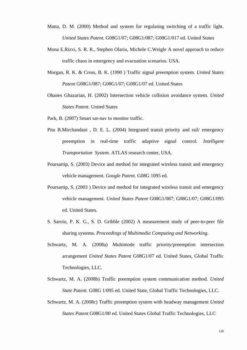
Matta, D. M. (2000) Method and system for regulating switching of a traffic light.
United States Patent. G08G1/07; G08G1/087; G08G1/017 ed. United States
Mona E.Rizvi, S. R. R., Stephen Olariu, Michele C.Weigle A novel approach to reduce
traffic chaos in emergency and evacuation scenarios. USA.
Morgan, R. K. & Cross, B. K. (1990 ) Traffic signal preemption system. United States
Patent G08G1/087; G08G1/07; G08G1/07 ed. United States
Ohanes Ghazarian, H. (2002) Intersection vehicle collision avoidance system. United
States Patent. United States
Park, B. (2007) Smart sat-nav to monitor traffic.
Pitu B.Mirchandani , D. E. L. (2004) Integrated transit priority and rail/ emergency
preemption in real-time traffic adaptive signal control. Intelligent
Transportation System. ATLAS research center, USA.
Poursartip, S. (2003) Device and method for integrated wireless transit and emergency
vehicle management. Google Patent. G08G 1095 ed.
Poursartip, S. (2003 ) Device and method for integrated wireless transit and emergency
vehicle management. United States Patent G08G1/087; G08G1/07; G08G1/095
ed. United States.
S. Saroiu, P. K. G., S. D. Gribble (2002) A measurement study of peer-to-peer file
sharing systems. Proceedings of Multimedia Computing and Networking.
Schwartz, M. A. (2008a) Multimode traffic priority/preemption intersection
arrangement United States Patent G08G1/07 ed. United States, Global Traffic
Technologies, LLC.
Schwartz, M. A. (2008b) Traffic preemption system communication method. United
State Patent. G08G 1/095 ed. United State, Global Traffic Technologies, LLC.
Schwartz, M. A. (2008c) Traffic preemption system with headway management United
States Patent G08G1/00 ed. United States Global Traffic Technologies, LLC
128
Schwartz, M. A. (2008 ) Multimode traffic priority/preemption intersection
arrangement. United States Patent. G08G1/07 ed. United States, Global Traffic
Technologies, LLC.
Yang Chen, R. S., Shengqiang Wang (2006) Location based vehicle traffic signal alert
system. Google Patent. 340901000; 340907000 ed.
Yanyan Chen, M. G. H., Ioannis Kaparias (2003) Reliability analysis of road networks
and preplanning of emergency rescue path. Beijing University of Technology,
China.
Zhang, K. & Mclaren, T. V. (2007 ) Traffic signal priority system based on mobile
event. European Patent Application G08G1/123; G08G1/087 ed., Siemens VDO
Automotive Corporation.
129
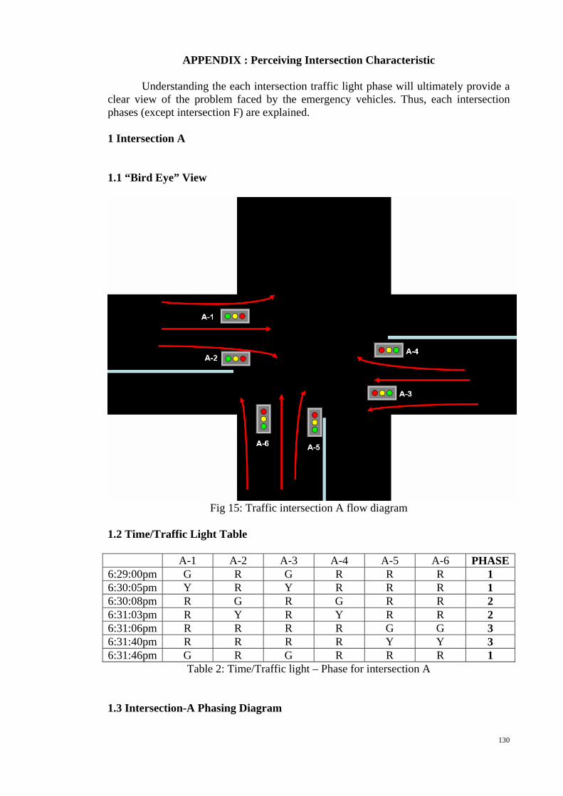
APPENDIX : Perceiving Intersection Characteristic Understanding the each intersection traffic light phase will ultimately provide a clear view of the problem faced by the emergency vehicles. Thus, each intersection phases (except intersection F) are explained. 1 Intersection A 1.1 “Bird Eye” View
Fig 15: Traffic intersection A flow diagram
1.2 Time/Traffic Light Table
A-1 A-2 A-3 A-4 A-5 A-6 PHASE6:29:00pm G R G R R R 1 6:30:05pm Y R Y R R R 1 6:30:08pm R G R G R R 2 6:31:03pm R Y R Y R R 2 6:31:06pm R R R R G G 3 6:31:40pm R R R R Y Y 3 6:31:46pm G R G R R R 1
Table 2: Time/Traffic light – Phase for intersection A 1.3 Intersection-A Phasing Diagram
130
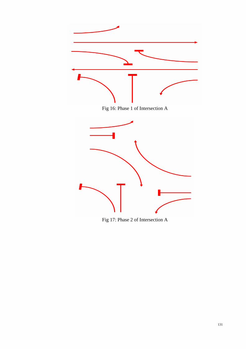
Fig 16: Phase 1 of Intersection A
Fig 17: Phase 2 of Intersection A
131
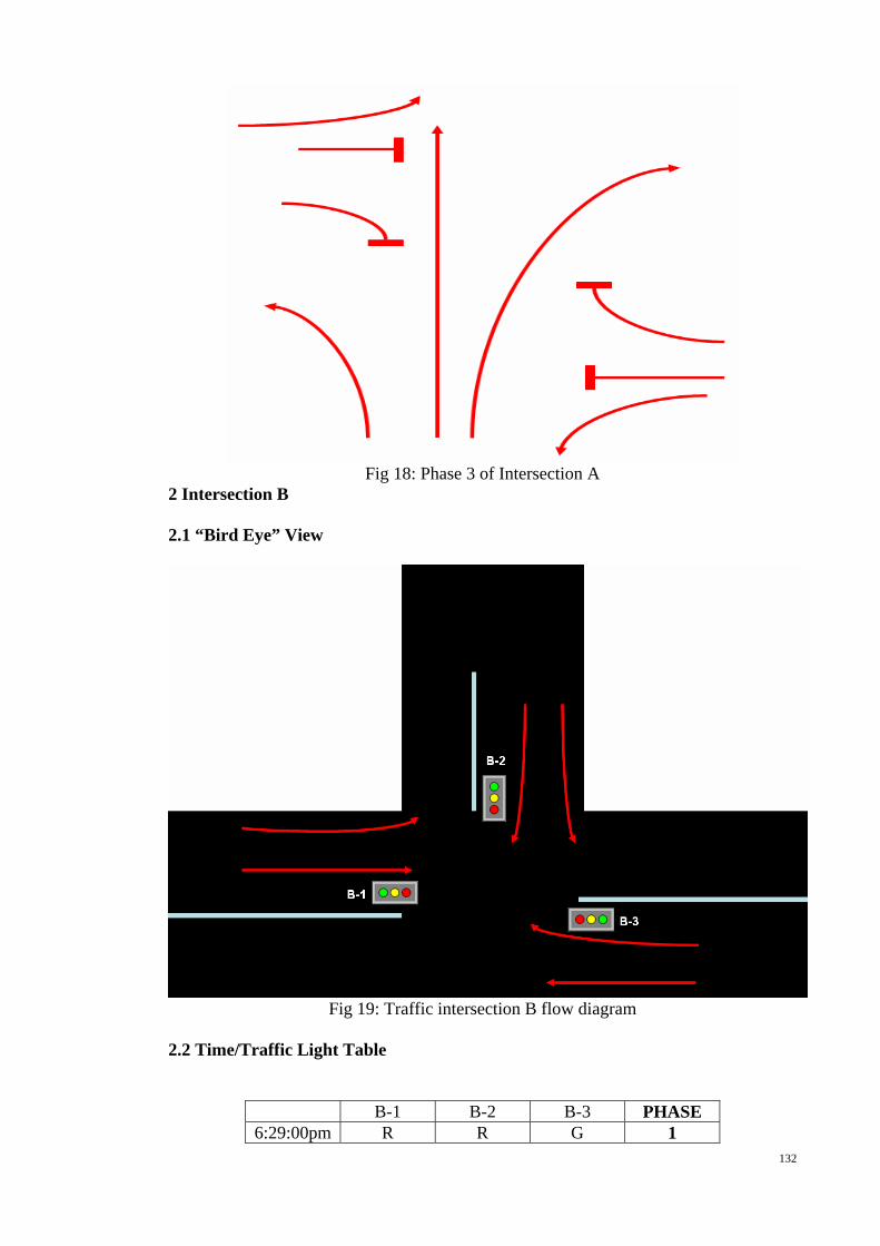
Fig 18: Phase 3 of Intersection A
2 Intersection B 2.1 “Bird Eye” View
Fig 19: Traffic intersection B flow diagram
2.2 Time/Traffic Light Table
B-1 B-2 B-3 PHASE 6:29:00pm R R G 1
132
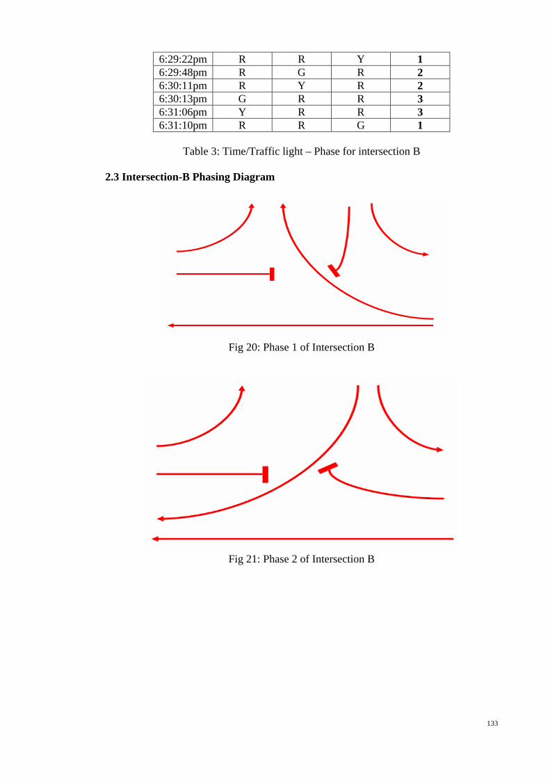
6:29:22pm R R Y 1 6:29:48pm R G R 2 6:30:11pm R Y R 2 6:30:13pm G R R 3 6:31:06pm Y R R 3 6:31:10pm R R G 1
Table 3: Time/Traffic light – Phase for intersection B
2.3 Intersection-B Phasing Diagram
Fig 20: Phase 1 of Intersection B
Fig 21: Phase 2 of Intersection B
133
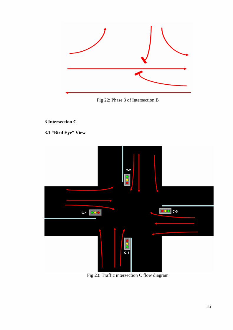
Fig 22: Phase 3 of Intersection B
3 Intersection C 3.1 “Bird Eye” View
Fig 23: Traffic intersection C flow diagram
134
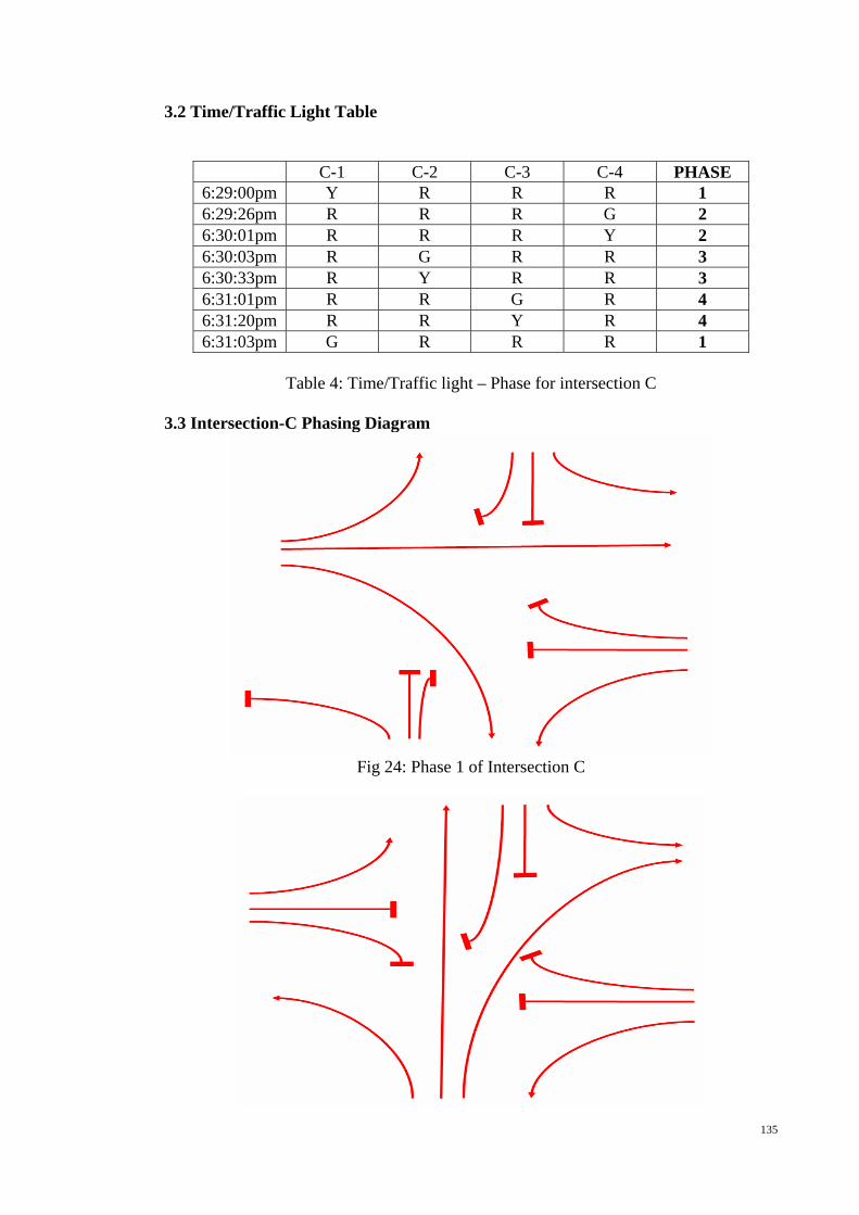
3.2 Time/Traffic Light Table
C-1 C-2 C-3 C-4 PHASE 6:29:00pm Y R R R 1 6:29:26pm R R R G 2 6:30:01pm R R R Y 2 6:30:03pm R G R R 3 6:30:33pm R Y R R 3 6:31:01pm R R G R 4 6:31:20pm R R Y R 4 6:31:03pm G R R R 1
Table 4: Time/Traffic light – Phase for intersection C
3.3 Intersection-C Phasing Diagram
Fig 24: Phase 1 of Intersection C
135
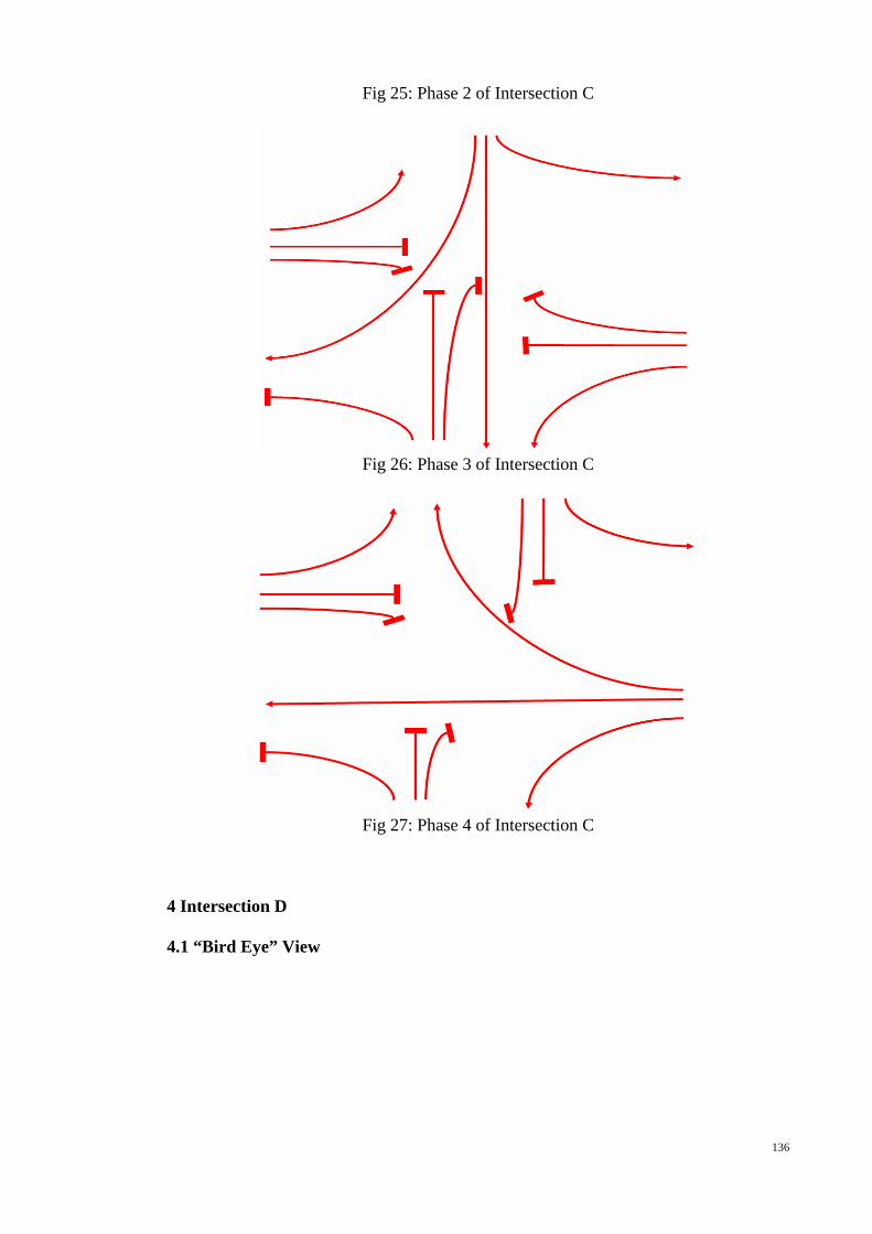
Fig 25: Phase 2 of Intersection C
Fig 26: Phase 3 of Intersection C
Fig 27: Phase 4 of Intersection C
4 Intersection D 4.1 “Bird Eye” View
136
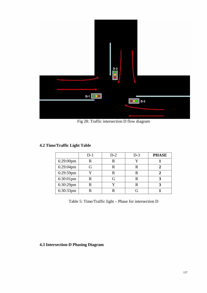
Fig 28: Traffic intersection D flow diagram
4.2 Time/Traffic Light Table
D-1 D-2 D-3 PHASE 6:29:00pm R R Y 1 6:29:04pm G R R 2 6:29:59pm Y R R 2 6:30:01pm R G R 3 6:30:29pm R Y R 3 6:30:33pm R R G 1
Table 5: Time/Traffic light – Phase for intersection D
4.3 Intersection-D Phasing Diagram
137
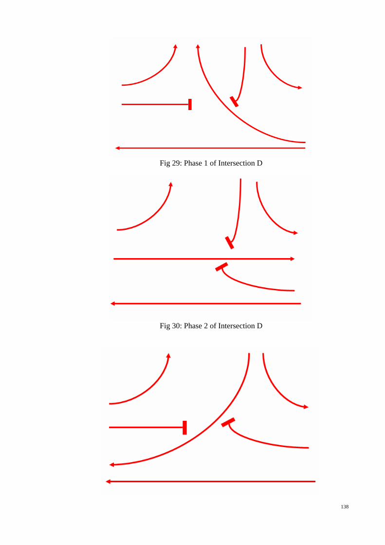
Fig 29: Phase 1 of Intersection D
Fig 30: Phase 2 of Intersection D
138

139
Fig 31: Phase 3 of Intersection D