Embed Size (px)
Citation preview
SMART Board® 600ixInteractive whiteboard systemConfiguration and user’s guide
Read this guide on your smart phone or other mobile device.

FCC warningThis equipment has been tested and found to comply with the limits for a Class A digital device, pursuant to Part 15 of the FCC Rules. These limits are designed to providereasonable protection against harmful interference when the equipment is operated in a commercial environment. This equipment generates, uses and can radiate radiofrequency energy and, if not installed and used in accordance with themanufacturer’s instructions, may cause harmful interference to radio communications. Operation ofthis equipment in a residential area is likely to cause harmful interference in which case the user will be required to correct the interference at his own expense.
Trademark noticeSMART Board, SMART Notebook, SMART Meeting Pro, Actalyst, SMART GoWire, SMART Bridgit, SMART Podium, SMART Hub, smarttech, the SMART logo and allSMART taglines are trademarks or registered trademarks of SMART Technologies ULC in the U.S. and/or other countries. Windows, Microsoft, Excel, PowerPoint andInternet Explorer are either registered trademarks or trademarks of Microsoft Corporation in the U.S. and/or other countries. Apple, Macintosh, Mac, iMac and PowerBookare trademarks of Apple Inc., registered in the U.S. and other countries. VESA is a registered trademark of The Video Electronics Standards Association. All other third-party product and company names may be trademarks of their respective owners.
Copyright notice© 2012 SMART Technologies ULC. All rights reserved. No part of this publicationmay be reproduced, transmitted, transcribed, stored in a retrieval system or translatedinto any language in any form by any means without the prior written consent of SMART Technologies ULC. Information in this manual is subject to change without noticeand does not represent a commitment on the part of SMART.One or more of the following patents: US6320597; US6326954; US6540366; US6741267; US7151533; US7687736; US7757001; USD616462; USD617332; and USD633546.Other patents pending.01/2012
Important informationBefore you install and use your SMART Board® 600ix interactive whiteboard system, read andunderstand the safety warnings and precautions in this user’s guide and the included warningsdocument. These safety warnings and precautions describe the safe and correct operation of yourinteractive whiteboard system and its accessories, helping you to prevent injuries and equipmentdamage. Ensure that your interactive whiteboard system is always being used correctly.
In this document, “interactive whiteboard system” refers to the following:
l SMART Board 600 series interactive whiteboard
l SMART UX60 projector
l Accessories and optional equipment
The projector included with your system is designed to work only with certain SMART Boardinteractive whiteboardmodels. Contact your authorized SMART reseller (smarttech.com/where) formore information.
Safety warnings, cautions and importantinformation
Installation
W WARN ING
l Failure to follow the installation instructions shipped with your SMART product could result inpersonal injury and damage to the product.
l To reduce the risk of fire or electric shock, do not expose the SMART product to rain ormoisture.
i
l Two people are required tomount your SMART product because it may be too heavy for oneperson to safely maneuver.
When you lift your interactive whiteboard, you and your assistant should stand on either sideof the screen, supporting its weight at the bottom while balancing the top with your otherhands.
l Whenmounting the projector boom on a framed or hollow wall, attach both themountingbracket and the safety tether to a stud to safely support the projector’s weight. If you use onlydrywall anchors, the drywall can fail, resulting in possible personal injury, and damage to theproduct whichmay not be covered by your warranty.
l Do not leave cables on the floor where they can be a tripping hazard. If youmust run a cableover the floor, lay it in a flat, straight line and secure it to the floor with tape or a cablemanagement strip of a contrasting color. Handle cables carefully and avoid excessivebending.
C CAUT ION
l Do not operate this unit immediately after moving it from a cold location to a warm location.When the unit is exposed to such a change in temperature, moisture can condense on thelens and crucial internal parts. Allow the system to stabilize to room temperature beforeoperation to prevent possible damage to the unit.
l Do not place the unit in hot locations, such as near heating equipment. Doing so could causeamalfunction and shorten the life of the projector.
l Avoid setting up and using the SMART product in an area with excessive levels of dust,humidity and smoke.
l Do not place your SMART product in direct sunlight or near any appliance that generates astrongmagnetic field.
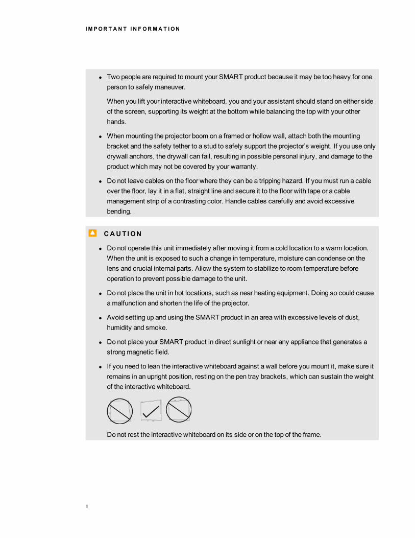
l If you need to lean the interactive whiteboard against a wall before youmount it, make sure itremains in an upright position, resting on the pen tray brackets, which can sustain the weightof the interactive whiteboard.
Do not rest the interactive whiteboard on its side or on the top of the frame.
I M POR T A N T I N F ORMA T I ON
ii
l Youmust connect the USB cable that camewith your SMART Board interactive whiteboardto a computer that has a USB compliant interface and that bears the USB logo. In addition,the USB source computer must be compliant with CSA/UL/EN 60950 and bear the CE markand CSA and/or ULMark(s) for CSA/UL 60950. This is for operating safety and to avoiddamage to the SMART Board interactive whiteboard.
I I MPORTANT
l Use theSMART Board 685ix and D685ix interactive whiteboard systems installationinstructions (smarttech.com/kb/137394) to install your interactive whiteboard, projector andECP.
l Make sure an electrical socket is near your SMART product and remains easily accessibleduring use.
l Using your SMART product near a TV or radio could cause interference to the images orsound. If this happens, move the TV or radio away from the projector.
Operation
W WARN ING
l If you are using an audio system, use only the power supply included with that product.Using the wrong power supply might create a safety hazard or damage the equipment. If indoubt, refer to the specification sheet for your product to verify the power supply type.
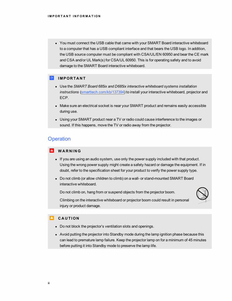
l Do not climb (or allow children to climb) on a wall- or stand-mounted SMART Boardinteractive whiteboard.
Do not climb on, hang from or suspend objects from the projector boom.
Climbing on the interactive whiteboard or projector boom could result in personalinjury or product damage.
C CAUT ION
l Do not block the projector’s ventilation slots and openings.
l Avoid putting the projector into Standby mode during the lamp ignition phase because thiscan lead to premature lamp failure. Keep the projector lamp on for aminimum of 45minutesbefore putting it into Standby mode to preserve the lamp life.
I M POR T A N T I N F ORMA T I ON
iii
l In a high altitude location over 6000' (1800m), where the air is thin and cooling efficiency isreduced, use the projector with the fanmode set to High.
l Cycling power to the projector repeatedly can lock or damage your SMART product. Afteryou put the product into Standby mode, wait at least 45minutes for cooling before startingthe product again.
l If dust or small items prevent pen tray buttons from being pressed or cause constant buttoncontact, remove the obstructions carefully.
I I MPORTANT
l If you have peripheral devices that do not use a 4-pin mini-DIN S-video connector, an RCAComposite video jack or an HDMI video connector, or if your device has an audio connectionthat does not use RCA jacks, youmay need to purchase third-party adapters.
l There are no projector menu options on the ECP. Keep your remote control in a safe placebecause the ECP is not a substitute for the remote control.
l Do not disconnect cables from the ECP to connect peripheral devices because you coulddisconnect controls for your interactive whiteboard.
l Disconnect the product from its power source when it’s not used for a long period.
Cleaning
C CAUT ION
l Before you clean the projector, press thePower button twice on the ECP or remotecontrol to put the system in Standby mode, and then allow the lamp to cool for at least 30minutes.
l Do not spray cleaners, solvents or compressed air near any part of the projector becausethey can damage or stain the unit. Spraying the system could spread a chemical mist onsome of the projector’s components and lamp, resulting in damage and poor image quality.
l Do not allow liquids or commercial solvents of any kind to flow into the projector.
I M POR T A N T I N F ORMA T I ON
iv
I I MPORTANT
l Put your SMART product into Standby mode before cleaning it.
l Follow these guidelines to clean the projector:
o Wipe the exterior of the projector with a lint-free cloth.
o If necessary, use a soft cloth moistened with amild detergent to clean the projectorhousing.
o Do not use abrasive cleaners, waxes or solvents.
o Avoid touching the lens. If it is necessary to clean the lens:
o Use liquids or commercial solvents (such as glass cleaners) to clean the lens,but do not spray them directly on the system.
o Use protective gloves and dip a lint-free cloth (such as Purestat PW2004) in ananti-static solvent (such as Hyperclean EE-6310).
o Gently wipe the lens from the center to the edge. Do not apply any pressure tothe lens.
Service
W WARN ING
l There are no user-serviceable parts inside the pen tray. Only qualified personnel shoulddisassemble the pen tray’s printed circuit boards, and this proceduremust be done withproper electrostatic discharge (ESD) protection.
C CAUT ION
l Do not adjust any settings in the servicemenu other than those listed in the followingprocedures. Changing other settings might damage or affect the operation of your projectorandmay invalidate your warranty.
l When transporting your SMART product, repack it with as much of the original packaging aspossible. This packaging was designed with optimal shock and vibration protection.
l If your SMART product requires replacement parts, make sure the service technician usesreplacement parts specified by SMART Technologies or parts with the same characteristicsas the original.
I M POR T A N T I N F ORMA T I ON
v

Environmental requirementsBefore you install your SMART Board 600 interactive whiteboard system, review the followingenvironmental requirements.
Environmentalrequirement
Parameter
Operating temperature l 41°F to 95°F (5°C to 35°C) from 0' to 6000' (0 m to 1800m)
l 41°F to 86°F (5°C to 30°C) from 6000' to 9800' (1800m to 3000m)
Storage temperature l -4°F to 104°F (-20°C to 40°C)
Humidity l 30% to 80% relative humidity, non-condensing
l Humidity above 80% could cause slight wrinkling in the screensurface sheet. The wrinkles disappear when the humidity lowers.
Water and fluidresistance
l Intended for indoor use only. Doesn’t meet any salt-spray or wateringress requirements.
l Don’t pour or spray liquids directly onto your interactive whiteboard,the projector or any of its sub-components.
Dust l Intended for use in office and classroom environments. Not forindustrial use where heavy dust and pollutants can causemalfunctions or impaired operation. Periodic cleaning is required inareas with heavier dust. SeeCleaning the projector on page 31 forinformation on cleaning the SMART UX60 projector.
l Designed for pollution degree 1 (P1) as per EN61558-1, which isdefined as “No pollution or only dry non-conductive pollution”.
Electrostatic discharge(ESD)
l EN61000-4-2 severity level 4 for direct and indirect ESD
l Nomalfunction or damage up to 8kV (both polarities) with a 330ohm, 150 pF probe (air discharge)
l Unmated connectors meet nomalfunction or damage up to 4kV(both polarities) for direct (contact) discharge
Cables l All SMART Board 600ix interactive whiteboard system cablesshould be shielded to prevent potential accidents and degradedvideo and audio quality.
Conducted and radiatedemissions
l EN55022/CISPR 22, Class A
I M POR T A N T I N F ORMA T I ON
vi
ContentsImportant information i
Safety warnings, cautions and important information iEnvironmental requirements vi
Chapter 1: About your interactive whiteboard system 1SMART Board 600ix interactive whiteboard system features 2Included accessories 5Optional accessories 6
Chapter 2: Installing your interactive whiteboard system 7Choosing a location 7Choosing a height 8Routing the cables 8Installing SMART software 8Locking the pen tray to your interactive whiteboard 9
Chapter 3: Using your interactive whiteboard system 11Using your projector 11Using your interactive whiteboard 24Using the Extended Control Panel (ECP) 24
Chapter 4: Integrating other devices 27Video format compatibility 27Connecting peripheral sources and outputs 30
Chapter 5: Maintaining your interactive whiteboard system 31Maintaining your interactive whiteboard 31Cleaning the projector 31Focusing and adjusting the projector image 32Replacing the projector lamp 33
Chapter 6: Troubleshooting your interactive whiteboard system 39Before you start 40Determining you interactive whiteboard system’s status 41Resolving interactive whiteboard issues 43Resolving projector issues 44Resolving ECP issues 50Accessing the servicemenu 50Transporting your interactive whiteboard system 51
vii

Appendix A: Remotely managing your system through a network interface 53Web pagemanagement 53Simple Network Management Protocol (SNMP) 60
Appendix B: Remotely managing your system through an RS-232 serial interface 61Connecting your room control system to the SMART UX60 projector 62Projector programming commands 64
Appendix C: Disabling user USB access 77
Appendix D: Remote control code definitions 81
Appendix E: Hardware environmental compliance 83Waste Electrical and Electronic Equipment regulations (WEEE directive) 83Restriction of Certain Hazardous Substances (RoHS directive) 83Batteries 83Packaging 84China’s Electronic Information Products regulations 84
Index 85
CON T EN T S
viii
Chapter 1: About your interactivewhiteboard systemSMART Board 600ix interactive whiteboard system features 2
SMART Board 600 series interactive whiteboard 2SMART UX60 projector 3Extended Control Panel (ECP) 4
Included accessories 5Remote control 5Pens 5Eraser 6
Optional accessories 6
Your SMART Board 600ix interactive whiteboard system combines the following components:
l SMART Board 600 series interactive whiteboard
l Wall-mounted, ultra-short-throw SMART UX60 projector
l Accessories and optional equipment
This chapter describes the features of your interactive whiteboard and provides information aboutproduct parts and accessories.
Chapter 1
1

SMART Board 600ix interactive whiteboardsystem featuresYour SMART Board 600ix interactive whiteboardsystem uses theWXGA (16:10) ultra-short-throw, high-offset SMART UX60 projector. YourSMART Board 600ix interactive whiteboardsystem delivers high-definition, high performanceinteractivity that is virtually shadow--free andglare--free.
When the SMART UX60 projector displays animage from a computer on the touch-sensitiveinteractive whiteboard, you can draw over theimage in digital ink using a pen or your finger.This projector also supports video and audioconnections from a variety of devices, includingDVD and Blu-ray™ players, VCRs, documentcameras, digital cameras and high-definitionsources, and can project media from these sources onto the interactive screen.
When you use SMART software with your SMART Board 600ix interactive whiteboard system, youcan write over any Ink Aware application in digital ink using a pen tray pen or your finger, and thensave these notes either in the application or to a .notebook file for future reference and distribution.
SMART Board 600 series interactive whiteboardYour SMART Board 600 series interactive whiteboard includes many features of earlierSMART Board interactive whiteboards, such as a resistive touch screen and a pen tray.
The SMART Board 600 series interactive whiteboard performs best with the SMART UX60 projectorbecause of its exceptional color performance, aspect ratio, input response and short-throw imagedistance.
CHA PT ER 1
About your interactive whiteboard system
2
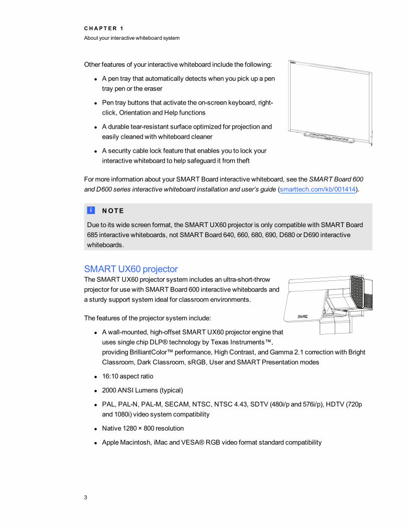
Other features of your interactive whiteboard include the following:
l A pen tray that automatically detects when you pick up a pentray pen or the eraser
l Pen tray buttons that activate the on-screen keyboard, right-click, Orientation and Help functions
l A durable tear-resistant surface optimized for projection andeasily cleaned with whiteboard cleaner
l A security cable lock feature that enables you to lock yourinteractive whiteboard to help safeguard it from theft
For more information about your SMART Board interactive whiteboard, see theSMART Board 600and D600 series interactive whiteboard installation and user’s guide (smarttech.com/kb/001414).
N NOTE
Due to its wide screen format, the SMART UX60 projector is only compatible with SMART Board685 interactive whiteboards, not SMART Board 640, 660, 680, 690, D680 or D690 interactivewhiteboards.
SMART UX60 projectorThe SMART UX60 projector system includes an ultra-short-throwprojector for use with SMART Board 600 interactive whiteboards anda sturdy support system ideal for classroom environments.
The features of the projector system include:
l A wall-mounted, high-offset SMART UX60 projector engine thatuses single chip DLP® technology by Texas Instruments™,providing BrilliantColor™ performance, High Contrast, andGamma 2.1 correction with BrightClassroom, Dark Classroom, sRGB, User and SMART Presentationmodes
l 16:10 aspect ratio
l 2000 ANSI Lumens (typical)
l PAL, PAL-N, PAL-M, SECAM, NTSC, NTSC 4.43, SDTV (480i/p and 576i/p), HDTV (720pand 1080i) video system compatibility
l Native 1280 × 800 resolution
l Apple Macintosh, iMac and VESA® RGB video format standard compatibility
CHA PT ER 1
About your interactive whiteboard system
3

l Remotemanagement via network through an RJ45 cable
OR
Remotemanagement via a serial RS-232 interface
l Self-protection timer for a hot re-strike of the projector lamp
l Protected cable routing through the projector housing and a cable cover that prevent tamperingand clutter
l Cleaning cloth for use on the projector lens and systemmirror
l Securemounting and installation system that includes:
o Two projector padlock loops
o Mounting hardware for solid masonry or framedwall installations
l Templates and instructions for positioning the system safely
Your SMART UX60 projector connection panel supports the following connectors:
l 3-pin mini-DIN connector
l 4-pin poweredmini-DIN connector and 7-pin mini-DIN connector
l S-video input and associated dual-channel audio input (two RCA jacks)
l HDMI connector input
l TwoHD-DB15 (VGA) inputs and associated audio input (3.5 mm jack) and one HD-DB15(VGA) output and associated audio output (3.5 mm jack) with additional interface support forComponent YPbPr and Component YCbCr inputs with proper adapters (not included)
l RJ45 cable for local area network connections
l RS-232 connector
l USB B receptacle for service access
Extended Control Panel (ECP)Your projector system’s ECP attaches to the bottom frameof your interactive whiteboard. The ECP features controlsfor power, source selection and volume adjustment, as wellas an integrated USB hub that enables you to switchseamlessly between two connected computers.
CHA PT ER 1
About your interactive whiteboard system
4

Connection receptacles for your source inputs include:
l OneUSB A receptacle on the front of the ECP for USB drives
l TwoUSB A receptacles behind the interactive whiteboard
l TwoRCA jacks on the front of the ECP for dual-channel audio input
l OneRCA jack on the front of the ECP for composite video input
l One captive USB B receptacle for your primary computer
l OneDB15M receptacle behind the interactive whiteboard for connecting to the projector
l OneUSB B receptacle behind the interactive whiteboard for connecting a secondary computer
Included accessoriesThe following accessories are included with your interactive whiteboard system.
Remote controlThe remote control enables you to control the system and set up your projector. Use theremote control to access menu options, system information and input selection options.
PensThe pens have rubberized grip areas and are colored tomatch four colors ofdigital ink: black, red, green and blue.
You can use dry-erasemarkers to replace the included pens, as long asthey’re a similar shape, don’t scratch or mark your interactive whiteboardsurface and reflect infrared light. If the substitute doesn’t reflect infraredlight, the pen tray sensors might not detect the presence of the pen.
N NOTE
Some of SMART’s older pens aren’t designed to reflect infrared light and the pen tray sensors mightnot detect them reliably.
T T I P
Wrap light-colored tape around a substitute pen to improve the reflection of infrared light and helpwith tool detection.
CHA PT ER 1
About your interactive whiteboard system
5

EraserThe eraser resembles a rectangular chalkboard eraser. You can use asubstitute object, as long as it has a similar shape, reflects infrared light anddoesn’t scratch or mark the interactive whiteboard surface.
Optional accessoriesYou can add a variety of accessories to your interactive whiteboard to best meet your specific needs.Purchase these items from your authorized SMART reseller when you order your interactivewhiteboard system or later.
For more information on accessories, go to smarttech.com/accessories.
CHA PT ER 1
About your interactive whiteboard system
6
Chapter 2: Installing your interactivewhiteboard systemChoosing a location 7Choosing a height 8Routing the cables 8Installing SMART software 8Locking the pen tray to your interactive whiteboard 9
Consult the SMART Board 600ix interactive whiteboard system installation document included withyour product for instructions on how to install your product.
I I MPORTANT
Use theSMART Board 685ix and D685ix interactive whiteboard systems installation instructions(smarttech.com/kb/137394) to install your interactive whiteboard, projector and ECP.
This chapter provides additional considerations and details for installing your interactive whiteboardsystem.
Choosing a locationChoose a location for your interactive whiteboard system that’s far from bright light sources, such aswindows and strong overhead lighting. Bright light sources can cause distracting shadows on yourinteractive whiteboard and can reduce the contrast of the projected image.
Select a wall with a flat, regular surface and sufficient clearance to accommodate your interactivewhiteboard system. Install the projector and your interactive whiteboard on the same flat surface. Forbest presentation alignment, mount your interactive whiteboard system in a location that’s central toyour audience’s viewing direction.
For mobile or adjustable installation options, contact your authorized SMART reseller.
Chapter 2
7
Choosing a heightSMART includes amounting template with each interactive whiteboard system. If you lose thistemplate, contact your authorized SMART reseller. Using this template ensures that you can do thefollowing:
l Mount the projector at a safe height for head space clearance, while maintaining enough spacefor airflow and installation access above the unit.
l Position the projector at the correct height above your interactive whiteboard to align theprojected image with the touch screen.
Dimensions on the template recommend a distance from the floor suitable for adults of averageheight. You should consider the general height of your user community when you choose a positionfor your interactive whiteboard.
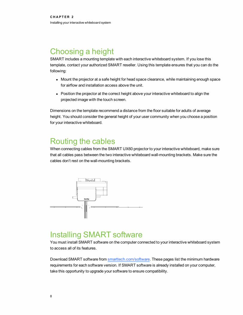
Routing the cablesWhen connecting cables from the SMART UX60 projector to your interactive whiteboard, make surethat all cables pass between the two interactive whiteboard wall-mounting brackets. Make sure thecables don’t rest on the wall-mounting brackets.
Installing SMART softwareYoumust install SMART software on the computer connected to your interactive whiteboard systemto access all of its features.
Download SMART software from smarttech.com/software. These pages list theminimum hardwarerequirements for each software version. If SMART software is already installed on your computer,take this opportunity to upgrade your software to ensure compatibility.
CHA PT ER 2
Installing your interactive whiteboard system
8
Locking the pen tray to your interactivewhiteboardTo learn how to lock the pen tray to your interactive whiteboard, see theSMART Board 600 and D600series interactive whiteboard installation and user’s guide (smarttech.com/kb/001414).
CHA PT ER 2
Installing your interactive whiteboard system
9

Chapter 3: Using your interactivewhiteboard systemUsing your projector 11
Using your remote control 11Replacing the remote control battery 12Using the remote control buttons 13Adjusting projector settings 14
Focusing the image 21Adjusting the image 22Projector connection diagram 22
Using your interactive whiteboard 24Using the Extended Control Panel (ECP) 24
This chapter describes the basic operation of your interactive whiteboard system and explains how toset up your remote control, retrieve system information, access the projector’s image adjustmentoptions and integrate your interactive whiteboard system with peripheral devices.
Using your projectorThis section explains how to use your projector and its included remote control.
Using your remote controlThe projector remote control enables you to access on-screen projector menus and change projectorsettings.
Chapter 3
11

Replacing the remote control batteryFollow this procedure to replace the remote control battery.
W WARN ING
l Reduce the risk associated with a leaking battery in the projector’s remote control byfollowing these practices:
o Use only the specified type of coin-cell battery.
o Orient the battery’s positive (+) and negative (–) terminals according to themarkingson the remote control.
o Remove the battery when the remote control is unused for an extended period.
o Do not heat, disassemble, short or recharge the battery, or expose it to fire or hightemperatures.
o Avoid eye and skin contact with the battery if it has a leak.
l Dispose of the exhausted battery and product components in accordance with applicableregulations.
g To replace the remote control battery
1. Hold down the side release on the left side of the battery holder and pull the battery holdercompletely out of the remote control.
2. Remove the old battery from the battery holder and replace it with a CR2025 coin-cell battery.
I I MPORTANT
Align the positive (+) and negative (–) signs on the battery terminals with the correct signs onthe battery holder.
3. Insert the battery holder into the remote control.
CHA PT ER 3
Using your interactive whiteboard system
12
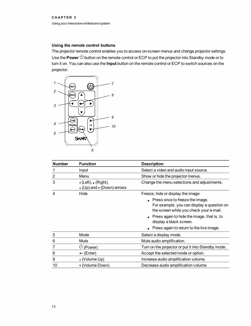
Using the remote control buttonsThe projector remote control enables you to access on-screenmenus and change projector settings.Use thePower button on the remote control or ECP to put the projector into Standby mode or toturn it on. You can also use the Input button on the remote control or ECP to switch sources on theprojector.
Number Function Description1 Input Select a video and audio input source.2 Menu Show or hide the projector menus.3 (Left), (Right),
(Up) and (Down) arrowsChange themenu selections and adjustments.
4 Hide Freeze, hide or display the image:l Press once to freeze the image.
For example, you can display a question onthe screen while you check your e-mail.
l Press again to hide the image, that is, todisplay a black screen.
l Press again to return to the live image.
5 Mode Select a display mode.6 Mute Mute audio amplification.7 (Power) Turn on the projector or put it into Standby mode.8 (Enter) Accept the selectedmode or option.9 (VolumeUp) Increase audio amplification volume.10 (VolumeDown) Decrease audio amplification volume.
CHA PT ER 3
Using your interactive whiteboard system
13
N NOTE
TheMute, Volume Up andVolume Down buttons work only if there is an audio source andspeaker system connected to the projector for the currently selected input source.
Adjusting projector settingsThe remote control’s Menu button enables you to access the on-screen display to adjust the projectorsettings.
I I MPORTANT
There are no projector menu options on the ECP. Keep your remote control in a safe place becausethe ECP is not a substitute for the remote control.
Setting Use Notes
Image Adjustment menuDisplay Mode Indicates the projector’s display output
(SMART Presentation,Bright Room, Dark Room, sRGBandUser).
The default is SMART Presentation.
Brightness Adjusts projector brightness from 0 to100.
The default is 50.
Contrast Adjusts the difference between thelightest and darkest partsof the image from 0 to 100.
The default is 50.
Frequency Adjusts the display data frequency ofthe projected image from -5 to 5 tomatch the frequency of yourcomputer’s graphics card.
The default is 0.This setting applies to VGA inputsonly.
Tracking Synchronizes your projector’s displaytiming with your computer’s graphicscard from 0 to 63.
This setting applies to VGA inputsonly.
H-position Moves the horizontal position of thesource video left or right from 0 to 100(relative to the projected image).
Don’t adjust this setting unless you’readvised to by SMART Support.Apply this setting only after youmakeall boom adjustments.This setting applies to VGA inputs onlyand is useful in situations where thesource video is cut off.
CHA PT ER 3
Using your interactive whiteboard system
14

Setting Use NotesV-position Moves the vertical position of the
source video up or down from -5 to 5(relative to the projected image).
Don’t adjust this setting unless you’readvised to by SMART Support.Apply this setting only after youmakeall boom adjustments.This setting applies to VGA inputs onlyand is useful in situations where thesource video is cut off.
Saturation Adjusts the projected image’s colorsaturation from 0 to 100.
This setting applies to S-video andComposite video inputs only.
Sharpness Adjusts the projected image’ssharpness from 0 to 31.
This setting applies to S-video andComposite video inputs only.
Tint Adjusts the image color balance of redand green from 0 to 100.
This setting applies to S-video andComposite video inputs only.
White Peaking Adjusts the image color brightnessfrom 0 to 10 while providingmorevibrant white shades.
A value closer to 0 creates a naturalimage and a value closer to 10enhances brightness.
Degamma Adjusts the color performance of thedisplay from 0 to 3.
Color Adjusts the Red, Green, Blue, Cyan,Magenta and Yellow colors on theprojector from 0 to 100 to providecustom color and luminance output.
Each color has a default value of 100.Adjustments to the color settingsregister under the User mode.
Audio menuVolume Adjusts the projector’s volume
amplification from -20 to 20.The default is 0.
Mute Mutes the projector’s audio output. The default is off.If youmute the projector’s audio outputand then increase or decrease thevolume, the volume is restoredautomatically. You can prevent thisfrom happening by disabling thevolume control.
Disable VolumeControl
Disables the projector’s volume controland the ECP’s volume control knob.
Closed Captioning Turns closed captioning on or off forvideo sources that support closedcaptioning.
Closed CaptioningLanguage
Sets the closed captioning language toCC1 orCC2.
Typically, CC1 displays U.S. Englishsubtitles, whileCC2 displays otherregional languages, such as French orSpanish, depending on televisionchannel or media setup.
CHA PT ER 3
Using your interactive whiteboard system
15

Setting Use Notes
Projector Functions menuAuto Signal Detect Enables or disables signal searching of
input connectors.The default is off.Select On to have the projectorcontinuously switch inputs until it findsan active video source.Select Off to maintain signal detectionin one input.
LampReminder Turns the lamp replacement reminderon or off.
This reminder appears 100 hoursbefore the recommended lampreplacement.
LampMode Adjusts lamp brightness toStandardorEconomy.
Standard displays a high-quality,bright image.Economy increases the lamp life bydecreasing the brightness of the image.
Auto Power Off(minutes)
Sets the length of the auto power-offcountdown timer between 1 and 240minutes.
The default is 120minutes.The timer begins to count downwhenthe projector no longer receives a videosignal. The timer finishes when theprojector enters Standby mode.Select 0 to turn off the timer.
Zoom Adjusts the zoom to the center of theimage in or out from 0 to 30.
The default is 0.Zooming in cuts off the outer edges ofthe source video.
Projector ID Sets the projector’s unique ID number(from 0 to 99) within your organization’snetwork.
You can refer to this number whenusing the network remotemanagementfeature (seeRemotely managing yoursystem through a network interface onpage 53).
CHA PT ER 3
Using your interactive whiteboard system
16
Setting Use NotesAspect Ratio Adjusts the image output to
Fill Screen,Match Input or 16:9.The default is Fill Screen.Fill Screen produces an image thatfills the entire screen by stretching andscaling the source video tomatch theprojector’s native resolution and aspectratio.Match Input displays the source videoin its native resolution and aspect ratio.As a result, unused space could appearalong the top and bottom edges of thescreen (letterbox format) or along theleft and right edges of the screen(pillarbox format).16:9 displays the source video in 16:9aspect ratio. As a result, unused spaceappears along the top and bottomedges of the screen. This isrecommended for use with HDTV andDVD/Blu-ray discs enhanced forwide-screen televisions.SeeVideo format compatibility onpage 27 for descriptions of eachmode.
Startup Screen Selects the type of startup screen(SMART, Capture User StartupScreen orPreview Startup Screen).
This screen displays when theprojector lamp is starting and a videosource signal isn’t displayed.SMART displays the default SMARTlogo on a blue background.Capture User Startup Screen closesthe on-screen display menu andcaptures the entire projected image.The captured image is displayed thenext time the on-screen display opens.(The capture can take up to oneminute, depending on the complexity ofthe background graphic.)Preview Startup Screen enables youto preview the default or capturedstartup screen.
CHA PT ER 3
Using your interactive whiteboard system
17
Setting Use NotesSet to Default? Resets projector settings to their
default values.If you select Yes, all projector settingsreset to their defaults, reversing anymenu changes youmade. This actionis irreversible.Don’t adjust this setting unless youwant to reset all of the applied settings,or unless you’re advised to by aSMART Support specialist.
USB1 Source Enables touch for the selected videosource (VGA-1, VGA-2, HDMI orDisabled) by associating the videosource with the room computer USBreceptacle (USB1) on the ECP.
The default is VGA-1.When the user switches to the videosource you select in this setting, theinteractive whiteboard recognizestouch from the device connected to theroom computer USB receptacle on theECP.SelectingDisabled disables the roomcomputer USB receptacle on the ECP.This setting was introduced in DDPfirmware version 1.0.0.4.
USB2 Source Enables touch for the selected videosource (VGA-1, VGA-2, HDMI orDisabled) by associating the videosource with the laptop USB receptacle(USB2) on the ECP.
The default is VGA-2.When the user switches to the videosource you select in this setting, theinteractive whiteboard recognizestouch from the device connected to thelaptop USB receptacle on the ECP.SelectingDisabled disables the laptopUSB receptacle on the ECP.This setting was introduced in DDPfirmware version 1.0.0.4.
CHA PT ER 3
Using your interactive whiteboard system
18
Setting Use Notes
Network menuNetwork and VGAOut
Activates the projector’s VGA Out andRJ45 connector and network features.
Status Displays the current network status(Connected, Disconnected orOff).
The default is off.
DHCP Displays the status of the network’sDynamic Host Configuration Protocol(DHCP) as On orOff.
The default is on.On enables a DHCP server on thenetwork to automatically assign an IPaddress to the projector.Off enables an administrator to assignan IP address manually.
PasswordReminder
E-mails the network password to thepredefined e-mail recipient.
SeeWeb pagemanagement on page53 to set up a destination e-mailaddress.
IP Address Displays the projector’s current IPaddress in values between 0.0.0.0 and255.255.255.255.
To change the projector’s IP address,use the RS-232 connector (seeNetwork controls on page 70) or use aDHCP server to assign a dynamic IPaddress, and then set a static IPaddress using the network remotemanagement feature (seeRemotelymanaging your system through anetwork interface on page 53).
Subnet Mask Displays the projector’s subnet masknumber in values between 0.0.0.0 and255.255.255.255.
Gateway Displays the projector’s defaultnetwork gateway in values between0.0.0.0 and 255.255.255.255.
DNS Displays the projector’s primarydomain name number in valuesbetween 0.0.0.0 and 255.255.255.255.
MAC Address Displays the projector’s MAC addressin xx-xx-xx-xx-xx-xx format.
Group Name Displays the projector’s workgroupname as set by an administrator(maximum 12 characters).
You can set the projector’s workgroupname using the remotemanagementfeatures (seeRemotely managing yoursystem through a network interface onpage 53 andRemotely managing yoursystem through an RS-232 serialinterface on page 61).
CHA PT ER 3
Using your interactive whiteboard system
19

Setting Use NotesProjector Name Displays the projector’s name as set
by an administrator (maximum 12characters).
You can set the projector’s name usingthe remotemanagement features (seeRemotely managing your systemthrough a network interface on page 53andRemotely managing your systemthrough an RS-232 serial interface onpage 61).
Location Displays the projector’s location as setby an administrator (maximum 16characters).
You can set the projector’s locationusing the remotemanagement features(seeRemotely managing your systemthrough a network interface on page 53andRemotely managing your systemthrough an RS-232 serial interface onpage 61).
Contact Displays the contact name or numberfor projector support as set by anadministrator (maximum 16characters).
You can set the contact name ornumber using the remotemanagementfeatures (seeRemotely managing yoursystem through a network interface onpage 53 andRemotely managing yoursystem through an RS-232 serialinterface on page 61).
Language menuLanguage Selects language preference. Projector menu support is available in
English (default), Chinese (Simplified),Chinese (Traditional), Czech, Danish,Dutch, Finnish, French, German,Greek, Italian, Japanese, Korean,Norwegian, Polish, Portuguese(Brazil), Portuguese (Portugal),Russian, Spanish and Swedish.
Information menuLampHours Displays the current number of lamp
usage hours from 0 to 4000 hours fromwhen it was last reset.
Always reset the lamp hours after youreplace a lamp, because lamp servicereminders are based on the currenthours of use. SeeResetting the lamphours on page 37 for details on thelamp hours reset procedure.
Input Displays the currently displayed videoinput source (VGA-1, VGA-2,Composite, S-Video, HDMI orNone).
CHA PT ER 3
Using your interactive whiteboard system
20

Setting Use NotesResolution Displays the projector’s most recently
detected video source signal resolutionand refresh rate.
If there is no current video input sourcesignal, this setting displays the lastknown source signal image resolutionand refresh rate.
Firmware Version Displays the projector’s digital displayprocessor (DDP) firmware version inx.x.x.x format.
MPU Version Displays the projector microprocessorunit (MPU) firmware version in x.x.x.xformat.
Network Version Displays the projector’s networkcommunications processor firmwareversion in x.x.x.x format.
If you haven’t enabled theNetworkand VGA Out setting, this setting isunable to display the projector’snetwork communications processorfirmware version and displays 0.0.0.0instead.
Model Number Displays the projector’s model number.Serial Number Displays the projector’s serial number.
Focusing the imageUse the focus dial located on the bottom of the SMART UX60 projector to focus the projected image.
g To focus and adjust the image
Turn the focus dial clockwise or counterclockwise until the image is in focus.
CHA PT ER 3
Using your interactive whiteboard system
21

Adjusting the imageRefer to these notes when adjusting the projected image as described in the includedSMART Board685ix and D685ix interactive whiteboard systems installation instructions(smarttech.com/kb/137394).
l While adjusting the projected image size, shape and location, use the projector’s defaultbackground so that you can see the full projected image clearly. Don’t use other images, whichmight be cropped or scaled by the projector and result in amisleading projected image size,shape, and location.
l Use themechanical adjustments described in the installation document to make all physicalimage adjustments. Don’t use the projector’s on-screenmenu options during the projectoralignment process.
l Make sure that the screws supporting the adjustment module are tightened so the projectordoesn’t move on the wall-mounting bracket’s track. Also, make sure that the image adjustmentrestrictors (screws and collars) are loosened when adjusting the image, or image adjustmentwill be difficult or impossible.
l Use only the color-coded control knobs on the top of the projector’s adjustment module andalways unlock the locking ring to adjust the projector’s image.
l Don’t touch the projector lens or mirror. This can disturb the focus or quality of image that yourprojector displays.
l When adjusting keystone (tilt), ensure that the top and bottom edges of the image arehorizontal before you position the left and right edges of the image relative to your interactivewhiteboard.
l To fine-tune the image, youmight need to repeat all steps described in the installationdocument in smaller increments.
Projector connection diagramYou can connect a variety of peripheral devices to your projector, including DVD/Blu-ray players,VCRs, document cameras, digital cameras and high-definition sources, as well as peripheral deviceoutputs such as a secondary projector or a flat-panel display and powered speakers.
N NOTE
Youmight need to purchase third-party adapters to connect certain peripheral devices.
CHA PT ER 3
Using your interactive whiteboard system
22
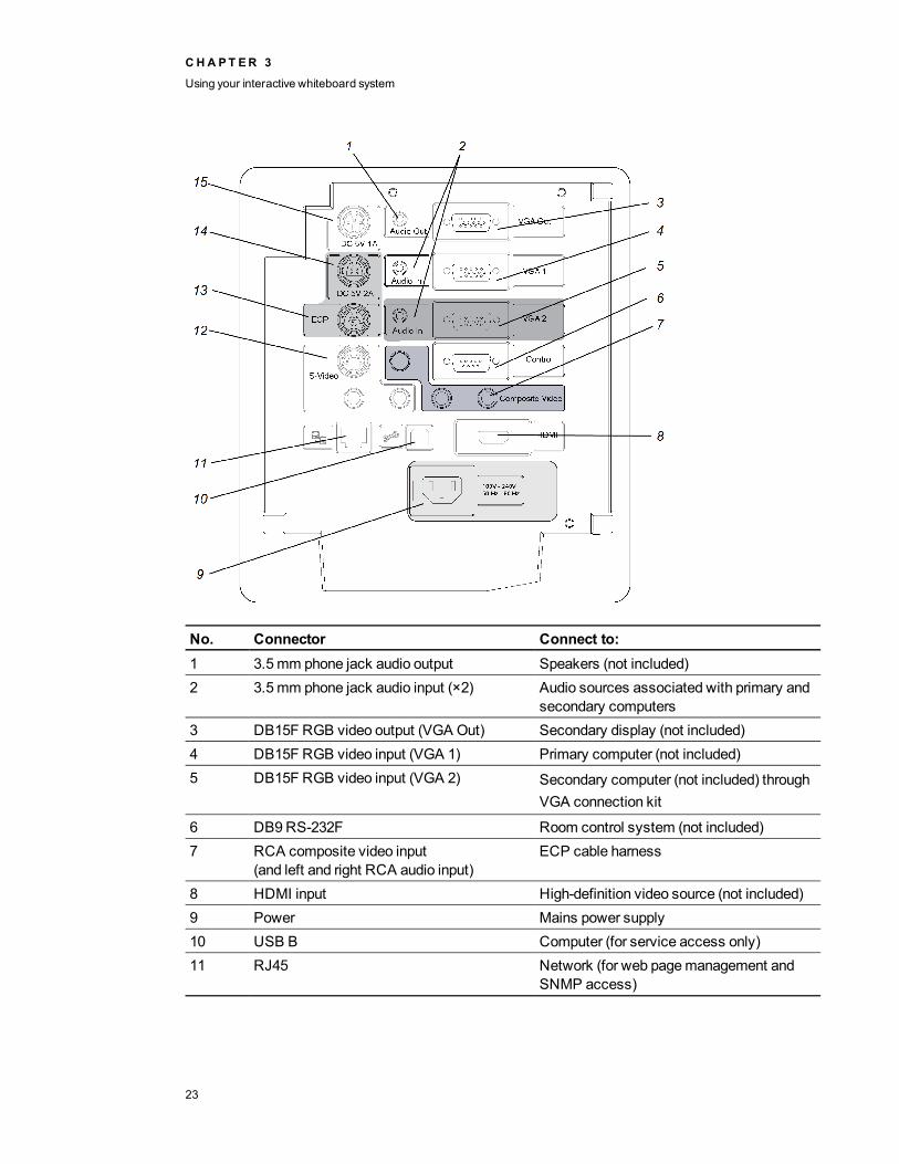
No. Connector Connect to:1 3.5mm phone jack audio output Speakers (not included)2 3.5mm phone jack audio input (×2) Audio sources associated with primary and
secondary computers3 DB15F RGB video output (VGA Out) Secondary display (not included)4 DB15F RGB video input (VGA 1) Primary computer (not included)5 DB15F RGB video input (VGA 2) Secondary computer (not included) through
VGA connection kit
6 DB9RS-232F Room control system (not included)7 RCA composite video input
(and left and right RCA audio input)ECP cable harness
8 HDMI input High-definition video source (not included)9 Power Mains power supply10 USB B Computer (for service access only)11 RJ45 Network (for web pagemanagement and
SNMP access)
CHA PT ER 3
Using your interactive whiteboard system
23

No. Connector Connect to:12 4-pin mini-DIN S-video input
(and left and right RCA audio input)Video source (not included)
13 7-pin mini-DIN ECP cable harness14 4-pin powermini-DIN 5V/2A output ECP cable harness15 3-pin powermini-DIN 5V/1A output [Not used]
N NOTES
l To connect your SMART Board 600 series interactive whiteboard, see theSMART Board600 and D600 series interactive whiteboard installation and user’s guide(smarttech.com/kb/001414).
l To connect accessories to your SMART Board interactive whiteboard, refer to thedocuments included with the accessories and consult the SMART Support website(smarttech.com/support) for additional information.
Using your interactive whiteboardRefer to theSMART Board 600 and D600 series interactive whiteboard installation and user’s guide(smarttech.com/kb/001414) for more information on using your interactive whiteboard.
When you connect your SMART Board interactive whiteboard to a computer with SMART software,you can access the full capabilities of your interactive whiteboard.
For more information on this software, press theHelp button on your interactive whiteboard pen tray.
For additional resources, go to smarttech.com, click the flag icon to the right of the SMART logo, andthen select your country and language. In the Support section of this website, you’ll find up-to-date,product-specific information, including setup instructions and specifications. TheSMART Learning Space (learningspace.smarttech.com) also has free learning resources, hands-onlessons and information on how to get more training.
Using the Extended Control Panel (ECP)The ECP gives you control of the basic operations of your interactive whiteboard system.Additionally, you can connect peripheral devices directly to the ECP, as described inConnectingperipheral sources and outputs on page 30. Press thePower button on the ECP or remote controlto put the projector system into Standby mode or turn it on. Press the Input button on the ECP orremote control to switch sources on the projector.
CHA PT ER 3
Using your interactive whiteboard system
24
I I MPORTANT
l There are no projector menu options on the ECP. Keep your remote control in a safe placebecause the ECP is not a substitute for the remote control.
l Do not disconnect cables from the ECP to connect peripheral devices because you coulddisconnect controls for your interactive whiteboard.
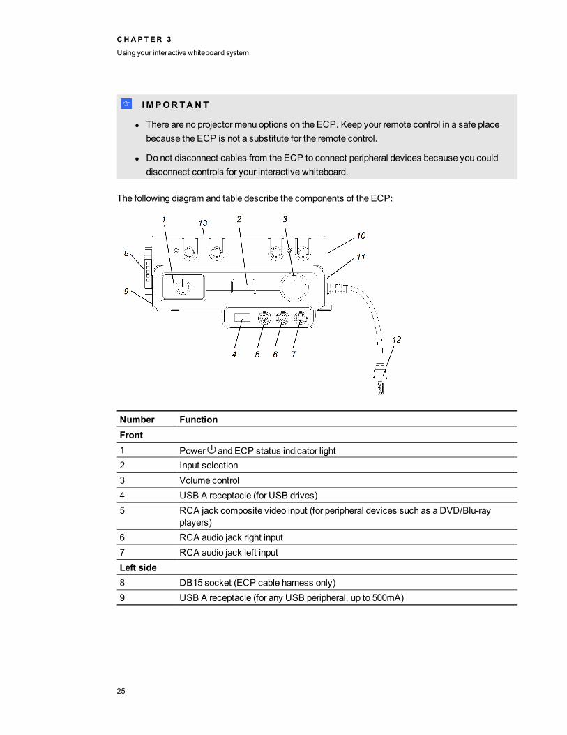
The following diagram and table describe the components of the ECP:
Number FunctionFront1 Power and ECP status indicator light2 Input selection3 Volume control4 USB A receptacle (for USB drives)5 RCA jack composite video input (for peripheral devices such as a DVD/Blu-ray
players)6 RCA audio jack right input7 RCA audio jack left inputLeft side8 DB15 socket (ECP cable harness only)9 USB A receptacle (for any USB peripheral, up to 500mA)
CHA PT ER 3
Using your interactive whiteboard system
25
Number FunctionRight side10 USB B receptacle (for a secondary computer such as a laptop)
N NOTE
This USB receptacle is active only when you select the associated video sourceas the projector input source. The associated video source is VGA2 by default, butyou can change it using the projector menu.
11 USB A receptacle (for SMART Board interactive whiteboard only)12 USB B receptacle (for your primary computer)
N NOTE
This USB receptacle is active only when you select the associated video sourceas the projector input source. The associated video source is VGA1 by default, butyou can change it using the projector menu.
Back13 RJ11 6-conductor receptacle (for SMART Hub™ SE collaboration platform control)
T T I P
If your computer has an HDMI output, you can connect a USB cable from your computer to either ofthe USB B receptacles on the ECP and an HDMI cable from your computer to the HDMI connectoron the projector. Associate the HDMI source with the appropriate USB receptacle (seeAdjustingprojector settings on page 14). Press the Input button on the ECP to switch to the HDMI input.
CHA PT ER 3
Using your interactive whiteboard system
26
Chapter 4: Integrating other devicesVideo format compatibility 27
Native video format 27Video format compatibility 28HD and SD signal format compatibility 29Video system signal compatibility 29
Connecting peripheral sources and outputs 30
This chapter provides information on integrating your SMART Board 600ix interactive whiteboardsystem with peripheral devices.
Video format compatibilityYour projector has a native video format and various video format compatibility modes. You canchange image appearances for certain formats and compatibilities.
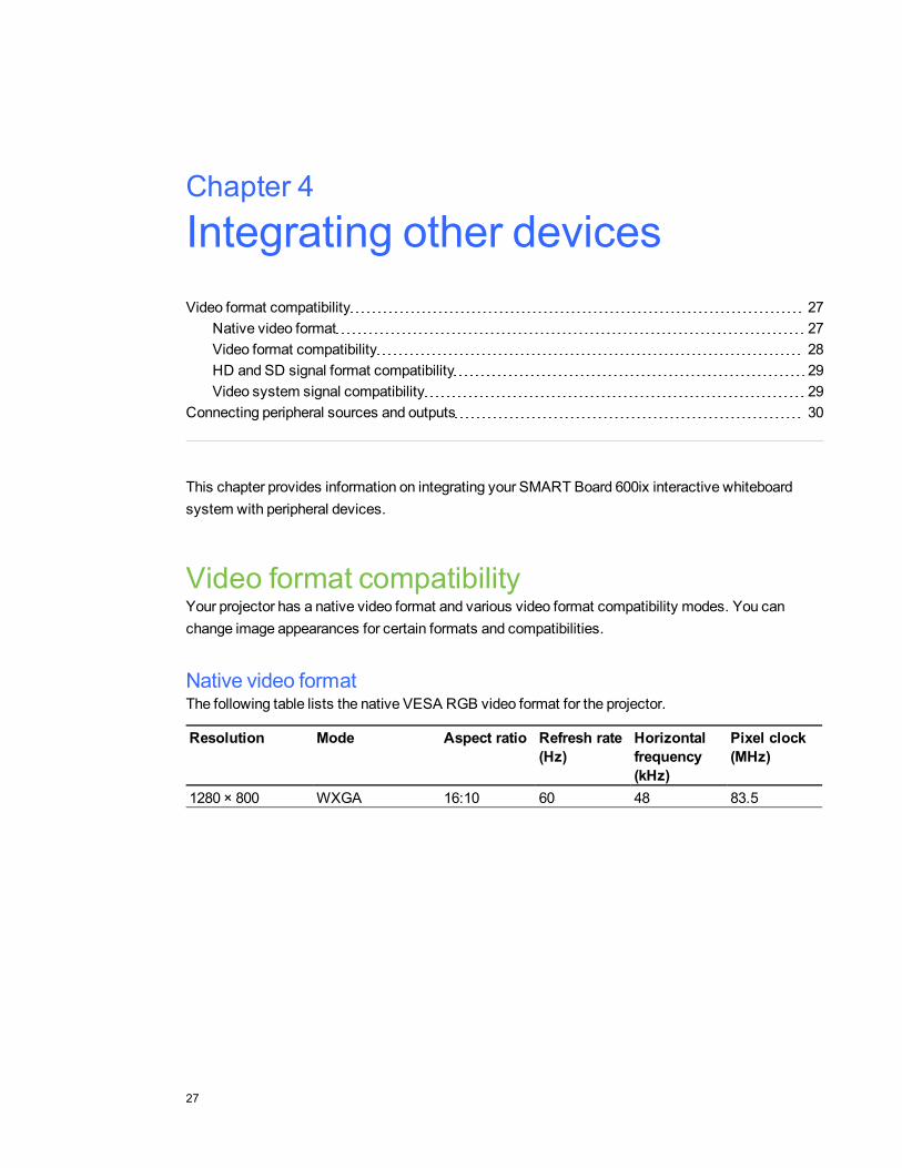
Native video formatThe following table lists the native VESA RGB video format for the projector.
Resolution Mode Aspect ratio Refresh rate(Hz)
Horizontalfrequency(kHz)
Pixel clock(MHz)
1280 × 800 WXGA 16:10 60 48 83.5
Chapter 4
27
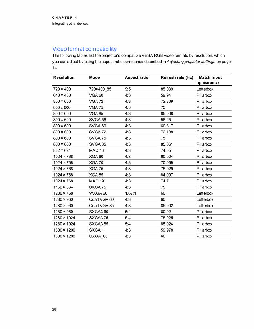
Video format compatibilityThe following tables list the projector’s compatible VESA RGB video formats by resolution, whichyou can adjust by using the aspect ratio commands described inAdjusting projector settings on page14.
Resolution Mode Aspect ratio Refresh rate (Hz) “Match Input”appearance
720 × 400 720×400_85 9:5 85.039 Letterbox640 × 480 VGA 60 4:3 59.94 Pillarbox800 × 600 VGA 72 4:3 72.809 Pillarbox800 x 600 VGA 75 4:3 75 Pillarbox800 × 600 VGA 85 4:3 85.008 Pillarbox800 × 600 SVGA 56 4:3 56.25 Pillarbox800 × 600 SVGA 60 4:3 60.317 Pillarbox800 × 600 SVGA 72 4:3 72.188 Pillarbox800 × 600 SVGA 75 4:3 75 Pillarbox800 × 600 SVGA 85 4:3 85.061 Pillarbox832 × 624 MAC 16" 4:3 74.55 Pillarbox1024 × 768 XGA 60 4:3 60.004 Pillarbox1024 × 768 XGA 70 4:3 70.069 Pillarbox1024 × 768 XGA 75 4:3 75.029 Pillarbox1024 × 768 XGA 85 4:3 84.997 Pillarbox1024 × 768 MAC 19" 4:3 74.7 Pillarbox1152 × 864 SXGA 75 4:3 75 Pillarbox1280 × 768 WXGA 60 1.67:1 60 Letterbox1280 × 960 Quad VGA 60 4:3 60 Letterbox1280 × 960 Quad VGA 85 4:3 85.002 Letterbox1280 × 960 SXGA3 60 5:4 60.02 Pillarbox1280 × 1024 SXGA3 75 5:4 75.025 Pillarbox1280 × 1024 SXGA3 85 5:4 85.024 Pillarbox1600 × 1200 SXGA+ 4:3 59.978 Pillarbox1600 × 1200 UXGA_60 4:3 60 Pillarbox
CHA PT ER 4
Integrating other devices
28

HDand SD signal format compatibilityThe following tables list the projector’s high definition and standard definition format signalcompatibility, which you can adjust by using the aspect ratio commands described inAdjustingprojector settings on page 14.
Signal format Aspect ratio Horizontalfrequency (kHz)
Verticalfrequency (Hz)
“Match Input”appearance
480i (525i) 4:3 15.73 59.94 Full screen480p (525p) 4:3 31.47 59.94 Full screen576i (625i) 5:4 15.63 50 Pillarbox576p (625p) 5:4 31.25 50 Pillarbox720p (750p) 16:9 45 59.94 Letterbox720p (750p) 16:9 37.5 50 Letterbox1080i (1125i) 16:9 33.75 59.94 Letterbox1080i (1125i) 16:9 28.13 50 Letterbox1080p (1125p) 16:9 67.5 59.94 Letterbox1080p (1125p) 16:9 56.25 50 Letterbox
N NOTE
Your projector is HD Ready. Its native resolution supports a pixel-perfect display of 720p sourcecontent. However, because the projector compresses 1080i source content to fit its nativeresolution, it doesn’t support a pixel-perfect display of 1080i source content.
Video system signal compatibilityThe following tables list the projector’s video system signal compatibility, particularly for signalsdelivered over S-Video and Composite video connectors, which you can adjust by using the aspectratio commands described inAdjusting projector settings on page 14.
Video mode Aspect ratio Horizontalfrequency (kHz)
Verticalfrequency (Hz)
Color signal(MHz)
NTSC 4:3 15.73 59.94 3.58PAL 4:3 15.63 50 4.43SECAM 4:3 15.63 50 4.25 and 4.41PAL-M 4:3 15.73 59.94 3.58PAL-N 4:3 15.63 50 3.58PAL-60 4:3 15.73 59.94 4.43NTSC 4.43 4:3 15.73 59.94 4.43
CHA PT ER 4
Integrating other devices
29
Connecting peripheral sources and outputsFollow these instructions if you have a peripheral device to connect to your interactive whiteboardsystem, such as a DVD/Blu-ray player or a USB device.
N NOTES
l Measure the distance between the projector and the peripheral device you want to connect.Make sure each cable is long enough, has plenty of slack and can be placed safely in yourroom without presenting a trip hazard.
l Do not disconnect cables from the ECP to connect peripheral devices because you coulddisconnect controls for your interactive whiteboard.
l Don’t connect SMART Board Audio (SBA-L) USB speakers to the ECP. Connect thesespeakers to the projector using a dual-channel (left and right) RCA plugs-to-3.5mm audioconnector cable (included with the speakers).
l The composite video connector and associated dual channel audio inputs on the ECP are forinput only. These RCA jacks don’t provide an output signal.
g To connect a peripheral source or output to your projector
1. If you have speakers installed, turn the volume dial on the ECP all the way down to preventbuzzing or a spark.
2. If your peripheral device uses a composite video connection, connect its input cables to theECP.
If your peripheral device uses a USB connection, connect its input cables to one of theavailable USB receptacles on the ECP.
3. Switch input sources to the peripheral device by pressing the Input button on the ECP orremote control.
N NOTE
If your USB device does not work, the devicemay bemalfunctioning or incompatible, or theUSB port may be disabled. SeeDisabling user USB access on page 77.
4. Restore the volume on the ECP’s volume dial.
CHA PT ER 4
Integrating other devices
30

Chapter 5: Maintaining your interactivewhiteboard systemMaintaining your interactive whiteboard 31Cleaning the projector 31Focusing and adjusting the projector image 32Replacing the projector lamp 33
Removing and replacing the projector lampmodule 33Resetting the lamp hours 37
This chapter includes methods for properly cleaning and preventing damage to yourSMART Board 600ix interactive whiteboard system.
Maintaining your interactive whiteboardFor information onmaintaining your interactive whiteboard, see theSMART Board 600 and D600series interactive whiteboard installation and user’s guide (smarttech.com/kb/001414).
Cleaning the projectorW WARN ING
Cleaning a wall-mounted projector can result in a fall or injury. Use caution when climbing a ladder,and consider removing the projector from its wall-mounting bracket to clean it.
C CAUT ION
l Never touch themirror with your hands or a brush, and do not scrub the surface of themirrorwith the supplied cleaning cloth. Instead, use the supplied cleaning cloth to clean themirrorwith a light touch, and do not put any cleaning solvents on the cloth or themirror.
Chapter 5
31
l Before you clean the projector, press thePower button twice on the ECP or remotecontrol to put the system in Standby mode, and then allow the lamp to cool for at least 30minutes.
l Do not spray cleaners, solvents or compressed air directly on the projector. Do not use spraycleaners or solvents near any part of the projector because they can damage or stain the unit.Spraying the system could spread a chemical mist on some of the projector’s componentsand lamp, resulting in damage and poor image quality.
l Do not allow liquids or commercial solvents of any kind to flow into the projector base orhead.
I I MPORTANT
l When cleaning the interactive whiteboard system:
o Wipe the exterior of the projector with a lint-free cloth.
o If necessary, use a soft cloth moistened with amild detergent to clean the projectorhousing.
l Do not use abrasive cleaners, waxes or solvents.
When cleaning the projector’s mirror:
l Use a bellows bulb or air blower bulb (commonly found in audio-visual supply stores) to blow offdust. Never touch themirror with your bare hands or a brush.
l If wiping themirror is unavoidable, wear protective gloves and gather the cleaning cloth into aball. Gently run the cleaning cloth across themirror like you would a feather duster.
When cleaning the projector’s lens:
l Use a bellows bulb or air blower bulb (commonly found in audio-visual supply stores) to blow offdust. Never touch the lens with your bare hands or a brush.
l If wiping the lens is unavoidable, wear protective gloves and gather the cleaning cloth into aball. Gently run the cleaning cloth across the lens from the center to the edge, using thecleaning cloth like you would a feather duster.
Focusing and adjusting the projector imageFor information on focusing and adjusting the projector image, see Focusing the image on page 21andAdjusting the image on page 22.
CHA PT ER 5
Maintaining your interactive whiteboard system
32

Replacing the projector lampThis section provides detailed instructions for replacing the projector lampmodule.
Removing and replacing the projector lampmoduleEventually the lampmodule will dim, and amessage will appear reminding you to replace the lamp.Make sure you have a replacement projector lamp before proceeding with the following instructions.
W WARN ING
l See smarttech.com/compliance for the projector’s MSDS documents.
l Replace the lampwhen the projector displays its lamp life warningmessage. If you continueto use the projector after this message appears, the lamp can shatter or burst, scatteringglass throughout the projector.
l If the lamp shatters or bursts, leave and then ventilate the area.
Next do the following:
o Avoid touching the glass fragments because they can cause injury.
o Wash your hands thoroughly if you have come into contact with lamp debris.
o Thoroughly clean the area around the projector, and discard any edible items placed inthat area because they could be contaminated.
o Call your authorized SMART reseller for instructions. Do not attempt to replace thelamp.
l Replacing the lamp in a wall-mounted projector can result in a fall or injury. Use caution whenclimbing a ladder, and consider removing the projector from the wall-mounting bracket toreplace the lamp.
l Uncovering the lampwhile the projector is mounted on the wall-mounting bracket can lead toproduct damage or personal injury from falling pieces of glass if the lamp is broken.
CHA PT ER 5
Maintaining your interactive whiteboard system
33

l When replacing the projector lamp:
o Put the projector into Standby mode and wait 30minutes for the lamp to coolcompletely.
o Do not remove any screws other than those specified in the lamp replacementinstructions.
o Wear protective eyewear while changing the lamp. Failure to do so can cause injuriesincluding loss of eyesight if the lamp shatters or bursts.
o Use only replacement lamps approved by SMART Technologies. Contact yourauthorized SMART reseller for replacement parts.
o Never replace the lamp assembly with a previously used lamp assembly.
o Always handle the fragile lamp assembly with care to prevent premature lamp failure orexposure tomercury. Use gloves when touching the lamp. Do not touch the lampwithyour fingers.
o Recycle or dispose of the lamp as hazardous waste in accordance with localregulations.
You need a Phillips No. 2 screwdriver and a flat screwdriver to complete these procedures.
g To remove the old lamp
1. Press thePower button twice on the remote control or the ECP to put the projector intoStandby mode.
2. Wait at least 30minutes for the projector to cool down.
3. Disconnect the power cable from the wall outlet.
CHA PT ER 5
Maintaining your interactive whiteboard system
34

4. Pull the lamp cover forward and remove it from the projector. Put the lamp cover in a safeplace.
T T I P
If the cover is difficult to remove, insert a flat screwdriver or small coin into the slot on thebottom of the lamp cover to gently pry the cover open.
5. Use a Phillips screwdriver to loosen the two captive screws from the bottom of the lampmodule.
N NOTE
Don’t try to remove these screws. Captive screws can’t be removed, but they must be loose.
6. Use the handle on the bottom of the lampmodule to slide out the lamp and remove it from theprojector.
CHA PT ER 5
Maintaining your interactive whiteboard system
35
g To put the new lamp module into the projector
1. Remove the new lampmodule from its packaging.
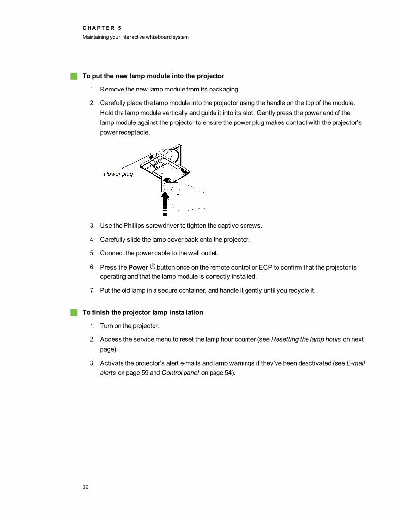
2. Carefully place the lampmodule into the projector using the handle on the top of themodule.Hold the lampmodule vertically and guide it into its slot. Gently press the power end of thelampmodule against the projector to ensure the power plugmakes contact with the projector’spower receptacle.
3. Use the Phillips screwdriver to tighten the captive screws.
4. Carefully slide the lamp cover back onto the projector.
5. Connect the power cable to the wall outlet.
6. Press thePower button once on the remote control or ECP to confirm that the projector isoperating and that the lampmodule is correctly installed.
7. Put the old lamp in a secure container, and handle it gently until you recycle it.
g To finish the projector lamp installation
1. Turn on the projector.
2. Access the servicemenu to reset the lamp hour counter (seeResetting the lamp hours on nextpage).
3. Activate the projector’s alert e-mails and lampwarnings if they’ve been deactivated (seeE-mailalerts on page 59 andControl panel on page 54).
CHA PT ER 5
Maintaining your interactive whiteboard system
36
Resetting the lamp hoursAfter you replace the lampmodule, you need to access the projector servicemenu and reset the lamphours. To prevent accidental errors, only a system administrator should perform this procedure.
N NOTE
Always reset the lamp hours after you replace the lamp, because lamp service reminders are basedon the current hours of use.
g To reset the lamp hours
1. Using the remote control, press the following buttons quickly to access the servicemenu:Down, Up, Up, Left, Up.
C CAUT ION
Do not adjust any settings in the servicemenu other than those listed in this guide. Changingother settings can damage or affect the operation of your projector andmay invalidate yourwarranty.
2. Scroll down to LampHour Reset, and then press Enter.
C CAUT ION
Do not reset the lamp hours unless you have just replaced the lampmodule. Resetting thelamp hours on an old lamp can damage your projector as a result of lamp failure.
3. Scroll down to theExit field, and press Enter to exit the projector servicemenu.
CHA PT ER 5
Maintaining your interactive whiteboard system
37

Chapter 6: Troubleshooting your interactivewhiteboard systemBefore you start 40
Locating status lights 40Locating serial numbers 40
Determining you interactive whiteboard system’s status 41Resolving interactive whiteboard issues 43
Resolving operation issues 43Resolving connection issues 43Resolving controller module issues 43
Resolving projector issues 44Resolving projector errors 44
Your projector stops responding 44The “Projector Overheated”, “Fan Failure” or “ColorWheel Failure” message appears 44The “Lamp Failure” message appears 45The projector Power and Service lights are off 45
Resolving image issues 46Loss of signal 46Partial, scrolling or incorrectly displayed image 47Unstable or flickering image 47Frozen image 48The image from your connected laptop computer isn’t projected 48Unaligned projected image 48
Resolving audio issues 49Resolving network communication issues 49
Resolving ECP issues 50Accessing the servicemenu 50
Retrieving your password 50Resetting the projector 51
Transporting your interactive whiteboard system 51
Chapter 6
39
This chapter provides basic troubleshooting information for your interactive whiteboard system.
For issues not covered in this chapter, consult the SMART Support website (smarttech.com/support)or contact your authorized SMART reseller (smarttech.com/where).
Before you startBefore you troubleshoot your interactive whiteboard system or contact your authorized SMARTreseller or SMART Support for assistance, you need to do the following:
l Locate your interactive whiteboard system’s status lights
l Locate your interactive whiteboard system’s serial numbers
Locating status lightsYou interactive whiteboard system consists of several components, which have their own statuslights:
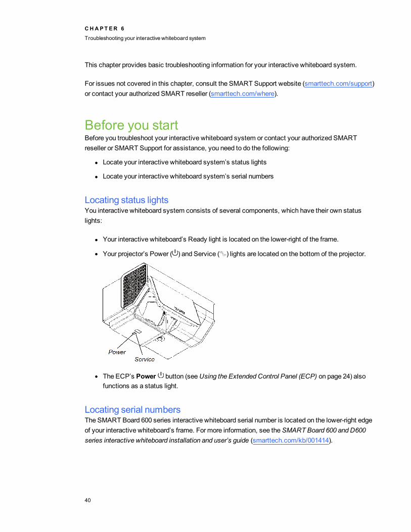
l Your interactive whiteboard’s Ready light is located on the lower-right of the frame.
l Your projector’s Power ( ) and Service ( ) lights are located on the bottom of the projector.
l The ECP’s Power button (seeUsing the Extended Control Panel (ECP) on page 24) alsofunctions as a status light.
Locating serial numbersThe SMART Board 600 series interactive whiteboard serial number is located on the lower-right edgeof your interactive whiteboard’s frame. For more information, see theSMART Board 600 and D600series interactive whiteboard installation and user’s guide (smarttech.com/kb/001414).
CHA PT ER 6
Troubleshooting your interactive whiteboard system
40
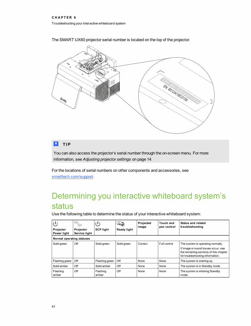
The SMART UX60 projector serial number is located on the top of the projector.
T T I P
You can also access the projector’s serial number through the on-screenmenu. For moreinformation, seeAdjusting projector settings on page 14.
For the locations of serial numbers on other components and accessories, seesmarttech.com/support.
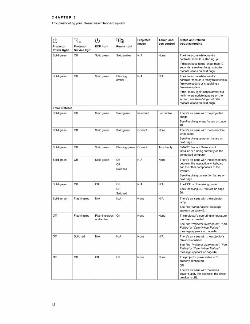
Determining you interactive whiteboard system’sstatusUse the following table to determine the status of your interactive whiteboard system:
ProjectorPower light
ProjectorService light
ECP light Ready light
Projectedimage
Touch andpen control
Status and relatedtroubleshooting
Normal operating statuses
Solid green Off Solid green Solid green Correct Full control The system is operating normally.If image or sound issues occur, seethe remaining sections of this chapterfor troubleshooting information.
Flashing green Off Flashing green Off None None The system is starting up.
Solid amber Off Solid amber Off None None The system is in Standby mode.
Flashingamber
Off Flashingamber
Off None None The system is entering Standbymode.
CHA PT ER 6
Troubleshooting your interactive whiteboard system
41
ProjectorPower light
ProjectorService light
ECP light Ready light
Projectedimage
Touch andpen control
Status and relatedtroubleshooting
Solid green Off Solid green Solid amber N/A None The interactive whiteboard’scontroller module is starting up.If this process takes longer than 10seconds, seeResolving controllermodule issues on next page.
Solid green Off Solid green Flashingamber
N/A N/A The interactive whiteboard’scontroller module is ready to receive afirmware update or is applying afirmware update.If the Ready light flashes amber butno firmware update appears on thescreen, seeResolving controllermodule issues on next page.
Error statuses
Solid green Off Solid green Solid green Incorrect Full control There’s an issue with the projectedimage.SeeResolving image issues on page46.
Solid green Off Solid green Solid green Correct None There’s an issue with the interactivewhiteboard.SeeResolving operation issues onnext page.
Solid green Off Solid green Flashing green Correct Touch only SMART Product Drivers isn’tinstalled or running correctly on theconnected computer.
Solid green Off Solid green OffORSolid red
N/A None There’s an issue with the connectionsbetween the interactive whiteboardand the other components of thesystem.SeeResolving connection issues onnext page.
Solid green Off Off OffORSolid red
N/A N/A The ECP isn’t receiving power.SeeResolving ECP issues on page50.
Solid amber Flashing red N/A N/A None N/A There’s an issue with the projectorlamp.See The “Lamp Failure” messageappears on page 45.
Off Flashing red Flashing greenand amber
Off None None The projector’s operating temperaturehas been exceeded.See The “Projector Overheated”, “FanFailure” or “Color Wheel Failure”message appears on page 44.
Off Solid red N/A N/A None N/A There’s an issue with the projector’sfan or color wheel.See The “Projector Overheated”, “FanFailure” or “Color Wheel Failure”message appears on page 44.
Off Off Off Off None None The projector power cable isn’tproperly connected.ORThere’s an issue with themainspower supply (for example, the circuitbreaker is off).
CHA PT ER 6
Troubleshooting your interactive whiteboard system
42
Resolving interactive whiteboard issuesThis section includes information on resolving issues with your interactive whiteboard.
For information not covered in this section, see theSMART Board 600 and D600 series interactivewhiteboard installation and user’s guide (smarttech.com/kb/001414).
Resolving operation issuesTo resolve operation issues, complete the following tasks:
l Confirm that the 4-wire cable (and 2-wire cable, if present) is connected to the interactivewhiteboard’s controller module.
l If necessary, complete additional troubleshooting with the guidance of SMART Support usingSMART Board Diagnostics.
Resolving connection issuesTo resolve connection issues, complete the following tasks:
l Confirm that the ECP cable harness’s 4-pin mini-DIN connector is properly connected to the5V 2A connector on the projector.
l Confirm that the USB cable is properly connected from the interactive whiteboard to the ECP.
l Confirm that the USB cable is properly connected from a fully functional USB receptacle on thecomputer to the correct USB receptacle on the ECP.
l Confirm that the projector’s on-screenmenu option for the USB receptacle is set to the correctvideo source.
l If necessary, complete additional troubleshooting on any devices between the USB connectionfrom the computer to the interactive whiteboard system, including any USB hubs andextension cables.
Resolving controller module issuesIf the controller module takes longer than 10 seconds to start up, disconnect the interactivewhiteboard’s USB cable, wait 10 seconds, and then reconnect it.
If the issue persists, update the firmware as documented in theSMART Board 600 and D600 seriesinteractive whiteboard installation and user’s guide (smarttech.com/kb/001414).
CHA PT ER 6
Troubleshooting your interactive whiteboard system
43

If the Ready light indicates that a firmware update is in progress but no update is actually takingplace, disconnect the interactive whiteboard’s USB cable, wait a few seconds, and then reconnect it.
Resolving projector issues
Resolving projector errorsSystem administrators can resolve the following projector errors on their own prior to contactingSMART Support. Performing initial troubleshooting on your projector will reduce the time of a supportcall.
Your projector stops respondingIf your projector stops responding, perform the following procedure.
g To restart an unresponsive projector
1. Put the projector into Standby mode, and then wait 30minutes for it to cool down.
2. Disconnect the power cable from the power outlet, and then wait at least 60 seconds.
3. Connect the power cable, and then turn on the projector.
The “Projector Overheated”, “Fan Failure” or “Color Wheel Failure” message appearsIf the “Projector Overheated”, “Fan Failure” or “ColorWheel Failure” message appears and theprojector stops projecting an image, one of the following issues is occurring:
l The projector is overheating internally because of blocked air vents or an internal temperatureover 131°F (55°C).
l The temperature outside the projector is too high.
l One of the fans has failed.
l The projector has a color wheel issue.
g To resolve the “Projector Overheated”, “Fan Failure” or “Color Wheel Failure” error
1. Put the projector into Standby mode, and then wait 30minutes for it to cool down.
2. If your room is hot, lower the temperature if possible.
3. Ensure that nothing is blocking the projector’s air intake and exhaust.
4. Disconnect the power cable from the power outlet, and then wait at least 60 seconds.
5. Connect the power cable, and then turn on the projector.
6. Adjust the fan speed using the servicemenu.
CHA PT ER 6
Troubleshooting your interactive whiteboard system
44
7. If the previous steps don’t resolve the issue, put the projector into Standby mode, disconnectthe power cable, and then contact your authorized SMART reseller.
The “Lamp Failure” message appearsIf the “Lamp Failure” message appears, one of the following issues is occurring:
l The lamp is overheating, likely due to blocked air vents.
l The lamp has reached the end of its life.
l The projector has an internal problem.
g To resolve the “Lamp Failure” error
1. Restart the projector (seeYour projector stops responding on previous page).
2. Check the remaining lamp hours using the on-screenmenu (seeAdjusting projector settings onpage 14).
If the lamp has more than 2000 hours of use, it’s near the end of its lifespan.
3. Replace your lamp as described inRemoving and replacing the projector lampmodule on page33.
4. If replacing the lampmodule doesn’t resolve the issue, put the projector into Standby mode,disconnect the power cable, and then contact your authorized SMART reseller.
The projector Power and Service lights are offIf the projector Power and Service lights are both off, one of the following issues is occurring:
l There was a power outage or a power surge.
l A circuit breaker or a safety switch was tripped.
l The projector isn’t connected to the power source.
l The projector has an internal problem.
g To resolve the unlit projector Power and Service lights issue
1. Check the power source, and thenmake sure that all cables are connected.
2. Confirm that the projector is connected to an active power outlet.
3. Make sure the pins on the connectors aren’t broken or bent.
4. Connect the power cable, and then turn on the projector.
5. If the previous steps don’t resolve the issue, disconnect the power cable and then contact yourauthorized SMART reseller.
CHA PT ER 6
Troubleshooting your interactive whiteboard system
45
Resolving image issuesTo resolve common image issues, complete the following tasks:
l Ensure the computer or other video source is on and set to display a resolution and refresh ratesupported by the projector (seeVideo format compatibility on page 27).
l Ensure the video source is properly connected to the projector.
l Press the Input Select button on the remote control or ECP to switch to the correct videosource.
If these tasks don’t resolve the issue, refer to the following sections for additional troubleshootinginformation.
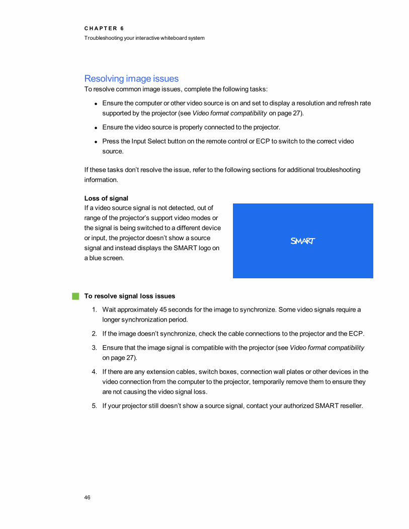
Loss of signalIf a video source signal is not detected, out ofrange of the projector’s support videomodes orthe signal is being switched to a different deviceor input, the projector doesn’t show a sourcesignal and instead displays the SMART logo ona blue screen.
g To resolve signal loss issues
1. Wait approximately 45 seconds for the image to synchronize. Some video signals require alonger synchronization period.
2. If the image doesn’t synchronize, check the cable connections to the projector and the ECP.
3. Ensure that the image signal is compatible with the projector (seeVideo format compatibilityon page 27).
4. If there are any extension cables, switch boxes, connection wall plates or other devices in thevideo connection from the computer to the projector, temporarily remove them to ensure theyare not causing the video signal loss.
5. If your projector still doesn’t show a source signal, contact your authorized SMART reseller.
CHA PT ER 6
Troubleshooting your interactive whiteboard system
46

Partial, scrolling or incorrectly displayed image
N NOTES
l The following procedure applies toWindows XP operating systems on desktop computersonly.
l This proceduremay vary depending on your version of Windows operating system and yoursystem preferences.
g To resolve a partial, scrolling or incorrectly displayed image
1. Select Start > Control Panel.
2. Double-click Display.
TheDisplay Properties window appears.
3. Click theSettings tab.
4. Verify that your display resolution setting is WXGA (1280 × 800).
5. Click Advanced, and then click theMonitor tab.
6. Verify that the screen refresh rate is 60 Hz.
Unstable or flickering imageIf the projector’s image is unstable or flickering, you could have different frequency or trackingsettings on your input source than on your projector.
I I MPORTANT
Write down your setting values before adjusting any of the settings in the following procedure.
g To resolve your unstable or flickering image
1. Adjust the Frequency, Tracking, H-position andV-position settings in the on-screenmenu.SeeAdjusting projector settings on page 14.
2. Check the display mode of your computer’s graphics card. Make sure it matches one of theprojector’s compatible signal formats (seeVideo format compatibility on page 27). Refer toyour computer’s manual for more information.
3. Configure the display mode of your computer’s graphics card tomake it compatible with theprojector. Refer to your computer’s manual for more information.
CHA PT ER 6
Troubleshooting your interactive whiteboard system
47
4. Optionally, reset the projector as described inResetting the projector on page 51 to adjust thefrequency and tracking to their original values.
I I MPORTANT
This action resets all values to their defaults.
Frozen imageIf your projector has a frozen image, perform the following procedure.
g To resolve a frozen image
1. Ensure that the Hide Display feature is off.
2. Press theHide button on the projector’s remote control to hide or show the display.
3. Ensure that your source device, such as your DVD player or computer, isn’t malfunctioning.
4. Put the projector into Standby mode, and then wait 30minutes for it to cool down.
5. Disconnect the power cable from the power outlet, and then wait at least 60 seconds.
6. Connect the power cable, and then turn on the projector.
7. If the previous steps don’t resolve the issue, contact your authorized SMART reseller.
The image from your connected laptop computer isn’t projectedLaptop computer settings can interfere with projector operations.
Some laptop computers deactivate their screens when you connect a secondary display device.Refer to your computer’s manual for details on reactivating the computer's display screen.
Unaligned projected imageAlignment errors occur when the projected image isn’t perpendicular to the screen. Alignment errorscan occur when youmount your interactive whiteboard system on an uneven surface or a wall thathas obstructions, or if you swivel the projector too far from the vertical center of your interactivewhiteboard.
Use the instructions in the includedSMART Board 685ix and D685ix interactive whiteboard systemsinstallation instructions (smarttech.com/kb/137394) to eliminatemost image alignment issues.
The projector image can slip if the projector is moved often or installed in a location prone to vibration,such as next to a heavy door. Follow these precautions to help prevent the image from becomingmisaligned:
l Make sure that the installation wall is plumb and square and doesn’t move or vibrateexcessively.
CHA PT ER 6
Troubleshooting your interactive whiteboard system
48

l Make sure that there are no obstructions behind the projector’s wall-mounting bracket, and thatthe bracket is firmly secured to the wall according to the installation instructions.
l Confirm that all cables are held in place with the appropriate cable clip.
l Adjust the projected image. See the includedSMART Board 685ix and D685ix interactivewhiteboard systems installation instructions (smarttech.com/kb/137394) andAdjusting theimage on page 22.
Resolving audio issuesThe projector doesn’t have integrated speakers, but you can connect an audio system to the audiooutput connector in the projector’s connection panel. If no sound is coming from your audio system,perform the following procedure.
g To resolve audio issues
1. Ensure that the speakers’ or audio system’s cables are properly connected to the audio outputplug on the projector’s connection panel.
2. Press theMute button on the projector’s remote control, and if AudioMute is on, turn it off.
3. Check the ECP’s volume knob or use the projector’s remote control to ensure that the volumeisn’t at the lowest setting.
4. Ensure that your speaker or audio system is on and that the volume is turned up.
5. Check that your source input, such as your computer or video device, isn’t malfunctioning.Ensure that its audio output is on and that the volume isn’t set to the lowest position.
N NOTE
Youmust display the source input’s video to play its audio through the connected speakersor audio system.
6. If the previous steps don’t resolve the issue, contact your authorized SMART reseller.
Resolving network communication issuesIf you don’t have network access, perform the following procedure to troubleshoot your system.
g To resolve network communication issues
1. Ensure that your network cable is properly connected to the RJ45 connection on the projector’sconnection panel.
CHA PT ER 6
Troubleshooting your interactive whiteboard system
49
2. Ensure that the LAN warning light on the projector is green. To activate the projector’s networkfeatures, use the “vgaoutnetenable=on” RS-232 command (seeProjector programmingcommands on page 64) or enable theNetwork and VGA Out setting (seeAdjusting projectorsettings on page 14). The network features on the projector don’t work until you complete oneof these tasks.
3. Press theMenu button, and then select theNetwork Settingsmenu to check the IP address.SeeAdjusting projector settings on page 14 for a description of the IP address field. Enter thisIP address into your browser or SNMP agent.
4. If you still don’t have network access, contact your network administrator. If your administratoris unable to resolve the issue, contact your authorized SMART reseller.
Resolving ECP issuesIf the ECP isn’t receiving power, complete the following tasks:
l Confirm that the ECP cable harness’s 11-pin connector is properly connected to the ECP.
l Confirm that the ECP cable harness’s 7-pin min-DIN connector is properly connected to theECP connector on the projector.
Accessing the service menuC CAUT ION
l To prevent tampering or unintentional changes, only system administrators should accessthe servicemenu. Do not share the servicemenu access code with casual users of yourinteractive whiteboard system.
l Do not adjust any settings in the servicemenu other than those listed in this guide. Changingother settings can damage or affect the operation of your projector andmay invalidate yourwarranty.
Retrieving your passwordIf you forget the projector’s password, you can retrieve it by accessing the projector servicemenudirectly from the projector or from the password settings menu on your projector’s web page (seePassword settings on page 59).
CHA PT ER 6
Troubleshooting your interactive whiteboard system
50
g To retrieve your password from the service menu
1. Using the remote control, press the following buttons quickly to access the servicemenu:Down, Up, Up, Left, Up.
2. Scroll toPassword Get, and then press Enter on the remote control.
The password appears on the screen.
3. Write down the password.
4. Scroll toExit, and then press Enter on the remote control to exit the projector servicemenu.
Resetting the projectorAt some point during troubleshooting, youmight need to reset all projector settings.
I I MPORTANT
This action is irreversible.
g To reset all projector settings
1. Using the remote control, press the following buttons quickly to access the servicemenu:Down, Up, Up, Left, Up.
2. Scroll to Factory Reset, and then press Enter on the remote control.
3. Scroll toExit, and then press Enter on the remote control to exit the projector servicemenu.
Transporting your interactive whiteboard systemSave your original SMART Board interactive whiteboard packaging so that it’s available if you need totransport your interactive whiteboard system. When required, repack it with all of the originalpackaging. This packaging was designed to provide optimal shock and vibration protection. If you nolonger have your original packaging, purchase the same packaging directly from your authorizedSMART reseller.
If you prefer to use your own packagingmaterials, make sure you adequately protect your unit. Makesure that the projector lens andmirror are protected against any physical contact or pressure whichmay damage the projector’s optics. Ship your interactive whiteboard in an upright position to detershippers from placing heavy objects on it.
CHA PT ER 6
Troubleshooting your interactive whiteboard system
51

Appendix A: Remotely managing your systemthrough a network interfaceWeb pagemanagement 53
Accessing web pagemanagement 53Home 54Control panel 54USB Control settings 57Network settings 57E-mail alerts 59Password settings 59
Simple Network Management Protocol (SNMP) 60
This appendix includes detailed instructions on how to remotely manage your SMART Board 600ixinteractive whiteboard system settings through a network interface.
Web page managementYou can access advanced setup features via the projector’s web page. This web page enables you tomanage the projector from a remote location using any computer connected to your intranet.
N NOTE
To access the web page, your browser must support JavaScript. Most commonly used browserslike Internet Explorer® and Firefox® support JavaScript.
Accessing web pagemanagementBefore you can access the web page, youmust connect the network cable to your projector (see theProjector connection diagram on page 22). When you first connect your projector to a network, an IPaddress appears on the on-screen display.
Appendix A
53

N NOTE
You can view the projector’s IP address by accessing the projector’s Network Settings menu page(seeNetwork settings on page 57).
g To use the management web page
1. Start your Internet browser.
2. Type the IP address in the address line field, and then press ENTER.
TheSMART UX60 Projector Settings window appears.
3. Select themenu options in the left pane to access the settings on each page.
4. Modify settings using your computer’s mouse and keyboard, and then click Submit or anotheraction button next to each setting you change.
HomeThe Homemenu page displays basic projector information and enables you to select the on-screendisplay language.
N NOTE
You can view basic projector information but you’re unable to change it (with the exception of theon-screen display language ) from the Homemenu page.
Submenu setting DescriptionLanguage Displays language optionsProjector Information Displays current projector information
Control panelThis menu enables you tomanage the projector audio and video status, alerts and appearances usingan Internet browser.
Submenu setting DescriptionPower Turns the projector on or puts it into Standby mode.
Select thePower ON orPower OFF button.Restore All ProjectorDefaults
Returns projector settings to default values or refreshes the currentsettings. Select Submit orRefresh.
I I MPORTANT
TheSubmit option is irreversible and resets all values.
A PPEN D I X A
Remotelymanaging your system through a network interface
54
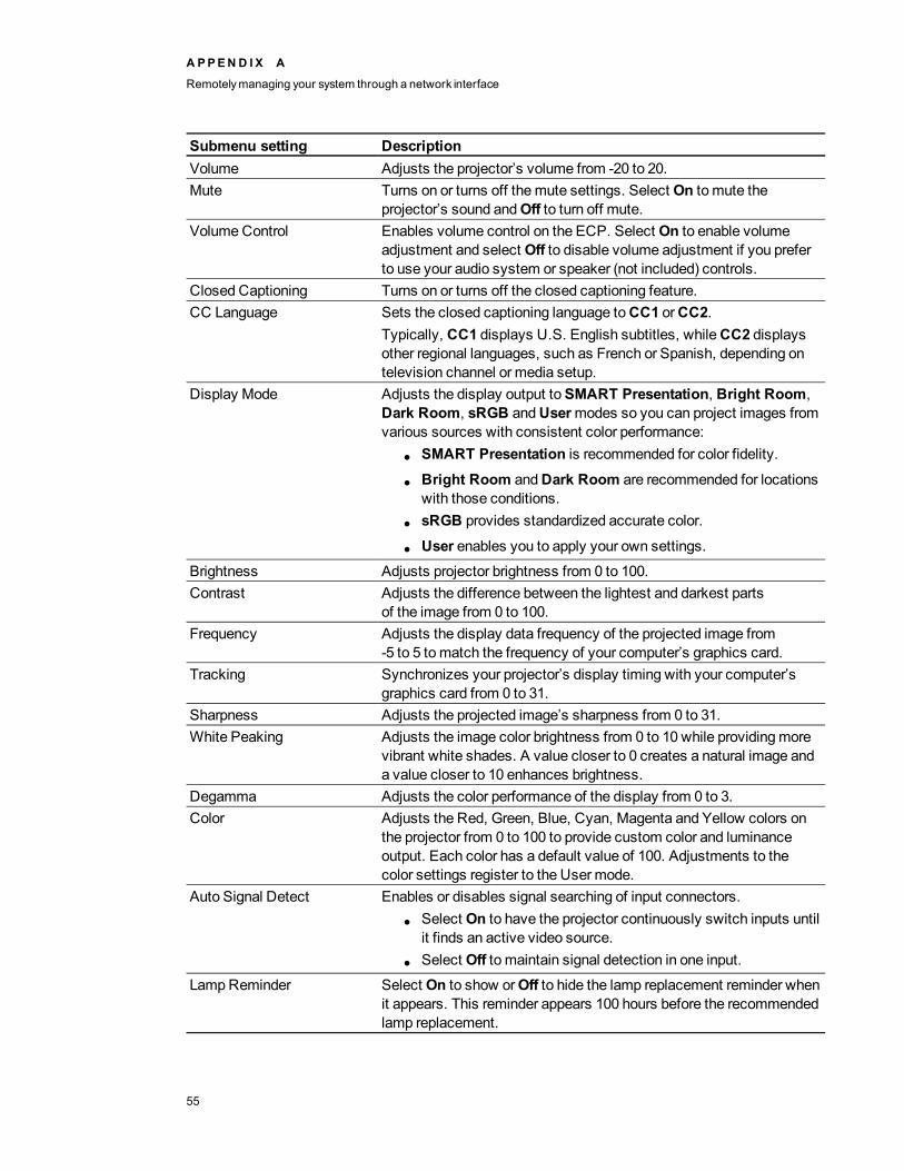
Submenu setting DescriptionVolume Adjusts the projector’s volume from -20 to 20.Mute Turns on or turns off themute settings. Select On to mute the
projector’s sound andOff to turn off mute.VolumeControl Enables volume control on the ECP. Select On to enable volume
adjustment and select Off to disable volume adjustment if you preferto use your audio system or speaker (not included) controls.
Closed Captioning Turns on or turns off the closed captioning feature.CC Language Sets the closed captioning language toCC1 orCC2.
Typically, CC1 displays U.S. English subtitles, whileCC2 displaysother regional languages, such as French or Spanish, depending ontelevision channel or media setup.
Display Mode Adjusts the display output toSMART Presentation, Bright Room,Dark Room, sRGB andUsermodes so you can project images fromvarious sources with consistent color performance:
l SMART Presentation is recommended for color fidelity.
l Bright Room andDark Room are recommended for locationswith those conditions.
l sRGB provides standardized accurate color.
l User enables you to apply your own settings.Brightness Adjusts projector brightness from 0 to 100.Contrast Adjusts the difference between the lightest and darkest parts
of the image from 0 to 100.Frequency Adjusts the display data frequency of the projected image from
-5 to 5 tomatch the frequency of your computer’s graphics card.Tracking Synchronizes your projector’s display timing with your computer’s
graphics card from 0 to 31.Sharpness Adjusts the projected image’s sharpness from 0 to 31.White Peaking Adjusts the image color brightness from 0 to 10 while providingmore
vibrant white shades. A value closer to 0 creates a natural image anda value closer to 10 enhances brightness.
Degamma Adjusts the color performance of the display from 0 to 3.Color Adjusts the Red, Green, Blue, Cyan, Magenta and Yellow colors on
the projector from 0 to 100 to provide custom color and luminanceoutput. Each color has a default value of 100. Adjustments to thecolor settings register to the User mode.
Auto Signal Detect Enables or disables signal searching of input connectors.l Select On to have the projector continuously switch inputs until
it finds an active video source.l Select Off to maintain signal detection in one input.
LampReminder Select On to show orOff to hide the lamp replacement reminder whenit appears. This reminder appears 100 hours before the recommendedlamp replacement.
A PPEN D I X A
Remotelymanaging your system through a network interface
55

Submenu setting DescriptionLampMode Adjusts lamp brightness toStandard orEconomy. Standard
displays a high-quality, bright image. Economy increases the lamplife by decreasing the brightness of the image.
Auto Power Off Sets the length of the auto power off countdown timer between 1 and240minutes. The timer begins to count downwhen the projector nolonger receives a video signal. The timer finishes when the projectorenters Standby mode. Select 0 to turn off the timer.
Zoom Adjusts the zoom to the center of the image in or out from0 to 30.
H-position (RGB input) Moves the horizontal position of the source video left or right from 0 to100 (relative to the projected image).
N NOTE
This is useful in situations where the source video is cut off.V-position (RGB input) Moves the vertical position of the source video up or down from -5 to 5
(relative to the projected image).
N NOTE
This is useful in situations where the source video is cut off.Aspect Ratio Adjusts the image output to Fill Screen,Match Input or 16:9.
l Fill Screen produces an image that fills the entire screen bystretching and scaling.
l Match Inputmatches the projector’s aspect ratio to the input’saspect ratio. As a result, black bands might appear along thetop and bottom edges of the screen horizontally (letterboxformat) or along the left and right edges of the screen vertically(pillarbox format).
l 16:9 changes the output to 16:9 by letterboxing the image,which is recommended for use with HDTV and DVDsenhanced for wide-screen television.
N NOTE
SeeVideo format compatibility on page 27 for appearancedescriptions in eachmode.
Startup Screen Sets the type of startup screen toSMART orUser. TheSMARTscreen is the default SMART logo on a blue background. TheUserscreen uses the saved picture from the Capture User Startup Screenfunction.
High Speed Fan Adjusts the speed of the projector’s fan. Select High orNormal.
N NOTE
Use the High setting when the projector’s temperature is high or thealtitude is above 6000' (1800m).
A PPEN D I X A
Remotelymanaging your system through a network interface
56

Submenu setting DescriptionProjector Mode Adjusts the projectionmode to Front, Ceiling, Rear orRear Ceiling.
I I MPORTANT
SMART recommends that you never change this setting from theCeiling projectionmode.
Source Adjusts the input source toVGA-1, VGA-2, Composite, S-Video orHDMI.
USBControl settingsThis menu allows you to associate a video source with a USB receptacle on the ECP.
Submenu setting DescriptionUSB1 Source Enables touch for the selected video source (VGA-1, VGA-2, HDMI
orDisabled) by associating the video source with the room computerUSB receptacle (USB1) on the ECP.
USB2 Source Enables touch for the selected video source (VGA-1, VGA-2, HDMIorDisabled) by associating the video source with the laptop USBreceptacle (USB2) on the ECP.
T T I P
These settings are only available for SMART UX60 projectors running DLP firmware version1.0.0.4 or later.
Network settingsThis menu allows you to use or not use Dynamic Host Control Protocol (DHCP) and to set thenetwork-related addresses and names when DHCP is not used.
Submenu setting DescriptionDHCP Determines if the projector’s IP address and other network settings
are dynamically assigned by a DHCP server or manually set.l On allows the network’s DHCP server to assign a dynamic IP
address to the projector.l Off allows you tomanually set the projector’s IP address and
other network settings.IP Address Displays or allows you to set the projector’s IP address in values
between 0.0.0.0 and 255.255.255.255.Subnet Mask Displays or allows you to set the projector’s subnet mask number in
values between 0.0.0.0 and 255.255.255.255.Gateway Displays or allows you to set the projector’s default network gateway
in values between 0.0.0.0 and 255.255.255.255.
A PPEN D I X A
Remotelymanaging your system through a network interface
57

Submenu setting DescriptionDNS Displays or allows you to set the projector’s IP address for your
network’s primary domain name server in values between 0.0.0.0 and255.255.255.255.
Group Name Displays or allows you to set the projector’s workgroup name(maximum 12 characters).
Projector Name Displays or allows you to set the projector’s name (maximum 12characters).
Location Displays or allows you to set the projector’s location (maximum 16characters).
Contact Displays or allows you to set the contact name or number for projectorsupport (maximum 16 characters).
SNMP Enable Turns the Simple Network Management Protocol (SNMP) agent on oroff.
Read-Only Community Sets a password that is required for each SNMP get request tothe device.
N NOTE
The default for Read-Only Community is public.Read/Write Community Sets a password that is required for each SNMP set request to the
device.
N NOTE
The default for Read/Write Community is private.Trap Destination Address Displays or allows you to set the IP address of the network’s SNMP
TRAP manager in values between 0.0.0.0 and 255.255.255.255. Thetrap destination address is the IP address of the computer assigned tohandle unsolicited data generated by SNMP TRAP events generatedby the projector, such as power state changes, projector failuremodes, a lamp needing to be replaced or other issues.
A PPEN D I X A
Remotelymanaging your system through a network interface
58
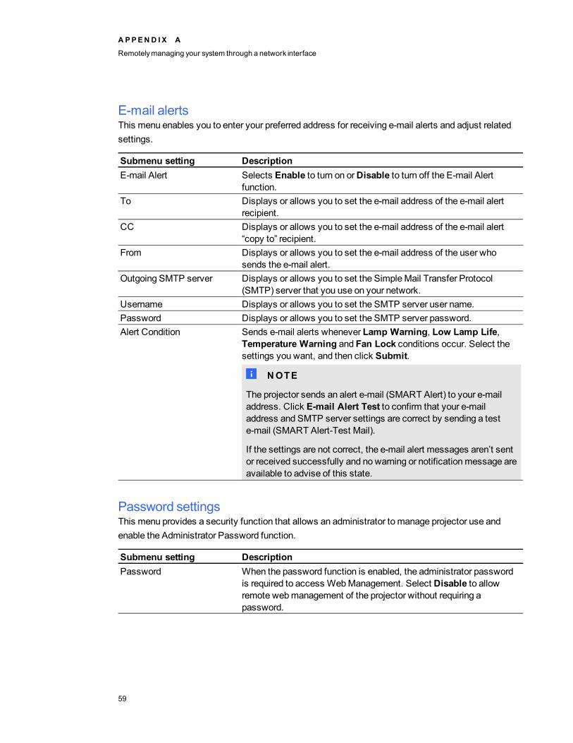
E-mail alertsThis menu enables you to enter your preferred address for receiving e-mail alerts and adjust relatedsettings.
Submenu setting DescriptionE-mail Alert Selects Enable to turn on orDisable to turn off the E-mail Alert
function.To Displays or allows you to set the e-mail address of the e-mail alert
recipient.CC Displays or allows you to set the e-mail address of the e-mail alert
“copy to” recipient.From Displays or allows you to set the e-mail address of the user who
sends the e-mail alert.Outgoing SMTP server Displays or allows you to set the SimpleMail Transfer Protocol
(SMTP) server that you use on your network.Username Displays or allows you to set the SMTP server user name.Password Displays or allows you to set the SMTP server password.Alert Condition Sends e-mail alerts whenever Lamp Warning, Low Lamp Life,
Temperature Warning and Fan Lock conditions occur. Select thesettings you want, and then click Submit.
N NOTE
The projector sends an alert e-mail (SMART Alert) to your e-mailaddress. Click E-mail Alert Test to confirm that your e-mailaddress and SMTP server settings are correct by sending a teste-mail (SMART Alert-Test Mail).
If the settings are not correct, the e-mail alert messages aren’t sentor received successfully and no warning or notificationmessage areavailable to advise of this state.
Password settingsThis menu provides a security function that allows an administrator to manage projector use andenable the Administrator Password function.
Submenu setting DescriptionPassword When the password function is enabled, the administrator password
is required to access WebManagement. Select Disable to allowremote webmanagement of the projector without requiring apassword.
A PPEN D I X A
Remotelymanaging your system through a network interface
59

N NOTES
l The first time you enable the password settings, the default password value is four numbers,for example, 1234.
l If you forget the projector password, refer toAccessing the servicemenu on page 50 to setthe projector setting to factory defaults.
Simple Network Management Protocol (SNMP)Your projector support a list of SNMP commands as described in themanagement information base(MIB) file. You can download this file by browsing to smarttech.com/software and clicking theMIBfiles link in theHardware section for the SMART UX60 projector.
The SNMP agent in your projector supports SNMP version 1 or 2. Upload theMIB file to your SNMPmanagement system application, and then use it as described in your application’s user guide.
A PPEN D I X A
Remotelymanaging your system through a network interface
60

Appendix B: Remotely managing your systemthrough an RS-232 serialinterfaceConnecting your room control system to the SMART UX60 projector 62
Pin configuration on the projector’s RS-232 connector 62Serial interface settings 62
Projector programming commands 64Projector power state controls 64Command inventory 64Value-based commandmethods 65
Absolute values and adjustment values 65Video source specification values 65
Power state controls 66Source selection controls 67General source controls 67Additional VGA source controls 69Additional Composite video source controls 69Audio controls 70Network controls 70System controls 72
This appendix includes detailed instructions on how to set up your computer or room control systemto remotely manage your SMART Board 600ix interactive whiteboard system settings through anRS-232 serial interface.
Appendix B
61
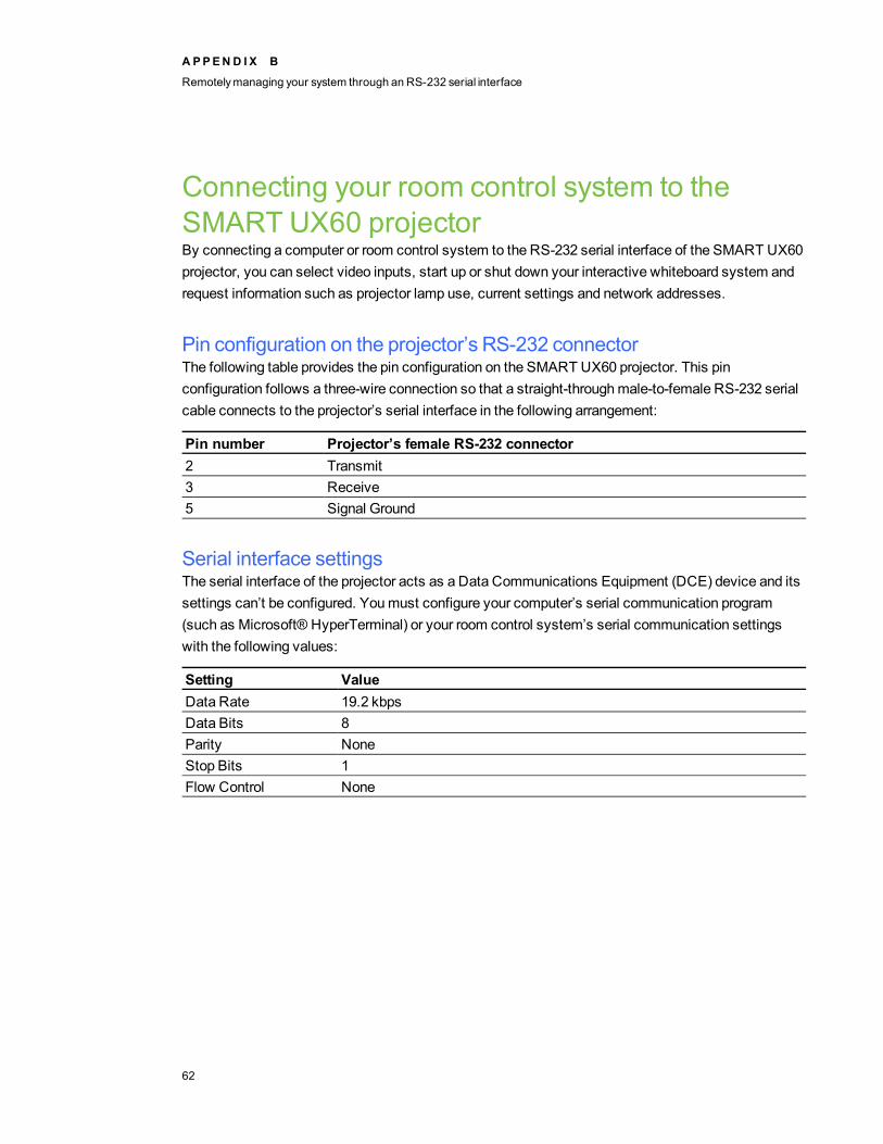
Connecting your room control system to theSMART UX60 projectorBy connecting a computer or room control system to the RS-232 serial interface of the SMART UX60projector, you can select video inputs, start up or shut down your interactive whiteboard system andrequest information such as projector lamp use, current settings and network addresses.
Pin configuration on the projector’s RS-232 connectorThe following table provides the pin configuration on the SMART UX60 projector. This pinconfiguration follows a three-wire connection so that a straight-throughmale-to-female RS-232 serialcable connects to the projector’s serial interface in the following arrangement:
Pin number Projector’s female RS-232 connector2 Transmit3 Receive5 Signal Ground
Serial interface settingsThe serial interface of the projector acts as a Data Communications Equipment (DCE) device and itssettings can’t be configured. Youmust configure your computer’s serial communication program(such as Microsoft® HyperTerminal) or your room control system’s serial communication settingswith the following values:
Setting ValueData Rate 19.2 kbpsData Bits 8Parity NoneStop Bits 1Flow Control None
A PPEN D I X B
Remotelymanaging your system through an RS-232 serial interface
62

N NOTES
l Asynchronous mode is disabled by default in the projector.
l All commands should be in ASCII format. Terminate all commands with a carriage return.
l All responses from the projector are terminated with a command prompt. Wait until youreceive the command prompt indicating that the system is ready for another command beforeyou continue.
l The room control feature of the projector is always on.
g To configure your computer’s serial interface
1. Turn on your computer, and then start your serial communications program or terminalemulation program.
2. Connect your computer to the serial connection cable you previously connected to theprojector.
3. Configure your serial interface settings using the values in the table in the previous section, andthen press ENTER.
The > character appears as a command prompt on the line that follows.
N NOTE
If nomessage or an error message appears, your serial interface configuration isn’t correct.Repeat step 3.
4. Type commands to configure your settings.
N NOTES
o To see a list of commands available in the current operatingmode, type ? and thenpress ENTER.
o If you’re using a terminal emulation program, turn on your program’s local echo settingto see characters as you type them.
A PPEN D I X B
Remotelymanaging your system through an RS-232 serial interface
63
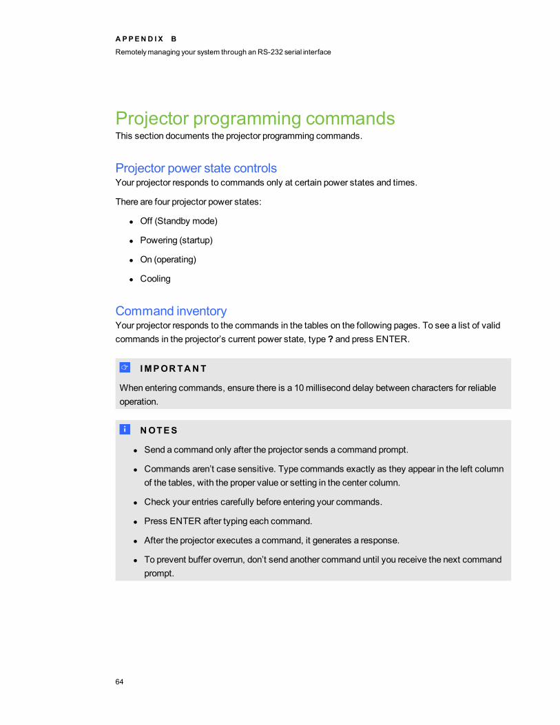
Projector programming commandsThis section documents the projector programming commands.
Projector power state controlsYour projector responds to commands only at certain power states and times.
There are four projector power states:
l Off (Standby mode)
l Powering (startup)
l On (operating)
l Cooling
Command inventoryYour projector responds to the commands in the tables on the following pages. To see a list of validcommands in the projector’s current power state, type ? and press ENTER.
I I MPORTANT
When entering commands, ensure there is a 10millisecond delay between characters for reliableoperation.
N NOTES
l Send a command only after the projector sends a command prompt.
l Commands aren’t case sensitive. Type commands exactly as they appear in the left columnof the tables, with the proper value or setting in the center column.
l Check your entries carefully before entering your commands.
l Press ENTER after typing each command.
l After the projector executes a command, it generates a response.
l To prevent buffer overrun, don’t send another command until you receive the next commandprompt.
A PPEN D I X B
Remotelymanaging your system through an RS-232 serial interface
64

Value-based commandmethods
Absolute values and adjustment valuesYou can use the command’s target range to set an absolute value for a command or cause anadjustment to bemade to the current value. To create an adjustment command, add a plus (+) orminus (-) symbol instead of the equal symbol (=) before the value change you want to enter.All absolute values you enter must be within the command target range, and all adjustment valuesmust equal a number within the command target range.
See the following examples for adjusting projector brightness:
>get brightness
brightness=55
>set brightness=65
brightness=65
>set brightness+5
brightness=70
>set brightness-15
brightness=55
Video source specification valuesYou can use the source input field described inSource selection controls on page 67 in a command toset an absolute value or adjustment value to a source other than the active source. You can do thiswhile the selected source is inactive, but the source devicemust be connected or you will receive aninvalid command response.
See the following examples, where both an HDMI connector and a VGA 1 input are connected:
>set input=hdmi
input=hdmi
>set brightness vga1=65
brightness vga1=65
A PPEN D I X B
Remotelymanaging your system through an RS-232 serial interface
65
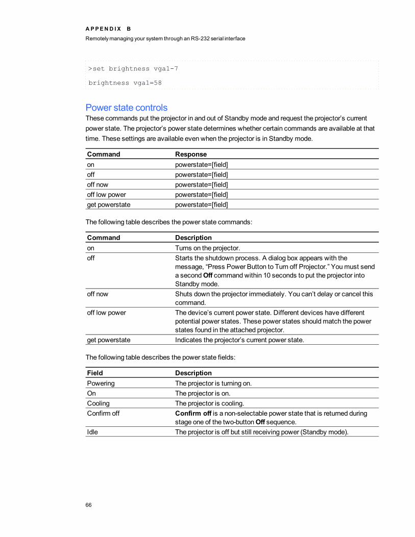
>set brightness vga1-7
brightness vga1=58
Power state controlsThese commands put the projector in and out of Standby mode and request the projector’s currentpower state. The projector’s power state determines whether certain commands are available at thattime. These settings are available even when the projector is in Standby mode.
Command Responseon powerstate=[field]off powerstate=[field]off now powerstate=[field]off low power powerstate=[field]get powerstate powerstate=[field]
The following table describes the power state commands:
Command Descriptionon Turns on the projector.off Starts the shutdown process. A dialog box appears with the
message, “Press Power Button to Turn off Projector.” Youmust senda secondOff commandwithin 10 seconds to put the projector intoStandby mode.
off now Shuts down the projector immediately. You can’t delay or cancel thiscommand.
off low power The device’s current power state. Different devices have differentpotential power states. These power states shouldmatch the powerstates found in the attached projector.
get powerstate Indicates the projector’s current power state.
The following table describes the power state fields:
Field DescriptionPowering The projector is turning on.On The projector is on.Cooling The projector is cooling.Confirm off Confirm off is a non-selectable power state that is returned during
stage one of the two-buttonOff sequence.Idle The projector is off but still receiving power (Standby mode).
A PPEN D I X B
Remotelymanaging your system through an RS-232 serial interface
66

Source selection controlsThese commands switch input sources. The source type determines which commands can beaccepted.
Command Response Available in Standbymode
get input input=[field] Yesset input=[field] input=[field] No
The following table describes the source selection commands:
Command Descriptionget input Returns the projector’s current input.set input=[field] Sets the input to one of the selectable fields.
The following table describes the source selection response fields:
Field DescriptionVGA1 Switches source to the VGA 1 input connector.VGA2 Switches source to the VGA 2 input connector.Composite Switches source to the Composite video connector.
If you installed your interactive whiteboard system according to theinstructions, this is the relay from the ECP.
HDMI Switches source to the HDMI input port.None A non-selectable value that appears when you enter a “get input”
commandwhile the projector is in Standby mode.
General source controlsThe following source controls apply to all input sources. HDMI connector source controls aredescribed in this section. These controls are unavailable when the projector is in Standby mode. Youcan specify custom color values for all inputs.
These commands inform you of the current source settings.
Command Responseget displaymode displaymode=[current display mode setting]get brightness brightness=[current brightness setting]get contrast contrast=[current contrast setting]get whitepeaking whitepeaking=[current whitepeaking setting]get degamma degamma=[current degamma setting]get red red=[current red color setting]get green green=[current green color setting]
A PPEN D I X B
Remotelymanaging your system through an RS-232 serial interface
67
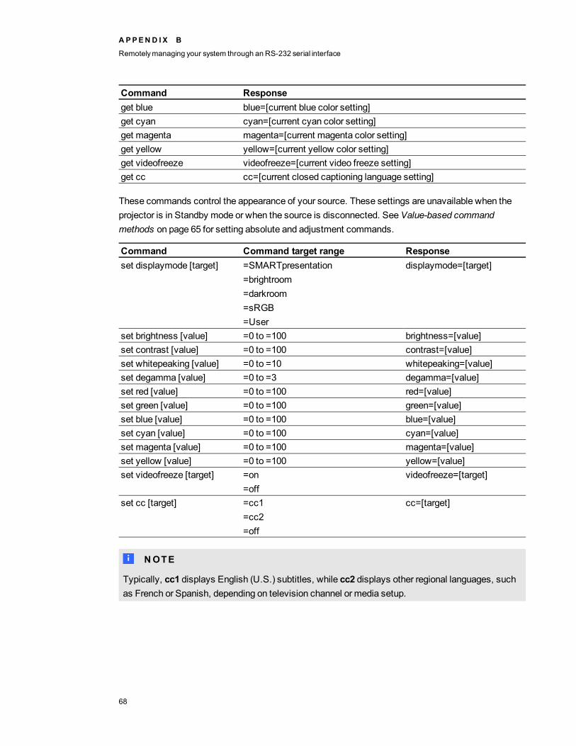
Command Responseget blue blue=[current blue color setting]get cyan cyan=[current cyan color setting]get magenta magenta=[current magenta color setting]get yellow yellow=[current yellow color setting]get videofreeze videofreeze=[current video freeze setting]get cc cc=[current closed captioning language setting]
These commands control the appearance of your source. These settings are unavailable when theprojector is in Standby mode or when the source is disconnected. SeeValue-based commandmethods on page 65 for setting absolute and adjustment commands.
Command Command target range Responseset displaymode [target] =SMARTpresentation
=brightroom=darkroom=sRGB=User
displaymode=[target]
set brightness [value] =0 to =100 brightness=[value]set contrast [value] =0 to =100 contrast=[value]set whitepeaking [value] =0 to =10 whitepeaking=[value]set degamma [value] =0 to =3 degamma=[value]set red [value] =0 to =100 red=[value]set green [value] =0 to =100 green=[value]set blue [value] =0 to =100 blue=[value]set cyan [value] =0 to =100 cyan=[value]set magenta [value] =0 to =100 magenta=[value]set yellow [value] =0 to =100 yellow=[value]set videofreeze [target] =on
=offvideofreeze=[target]
set cc [target] =cc1=cc2=off
cc=[target]
N NOTE
Typically, cc1 displays English (U.S.) subtitles, while cc2 displays other regional languages, suchas French or Spanish, depending on television channel or media setup.
A PPEN D I X B
Remotelymanaging your system through an RS-232 serial interface
68
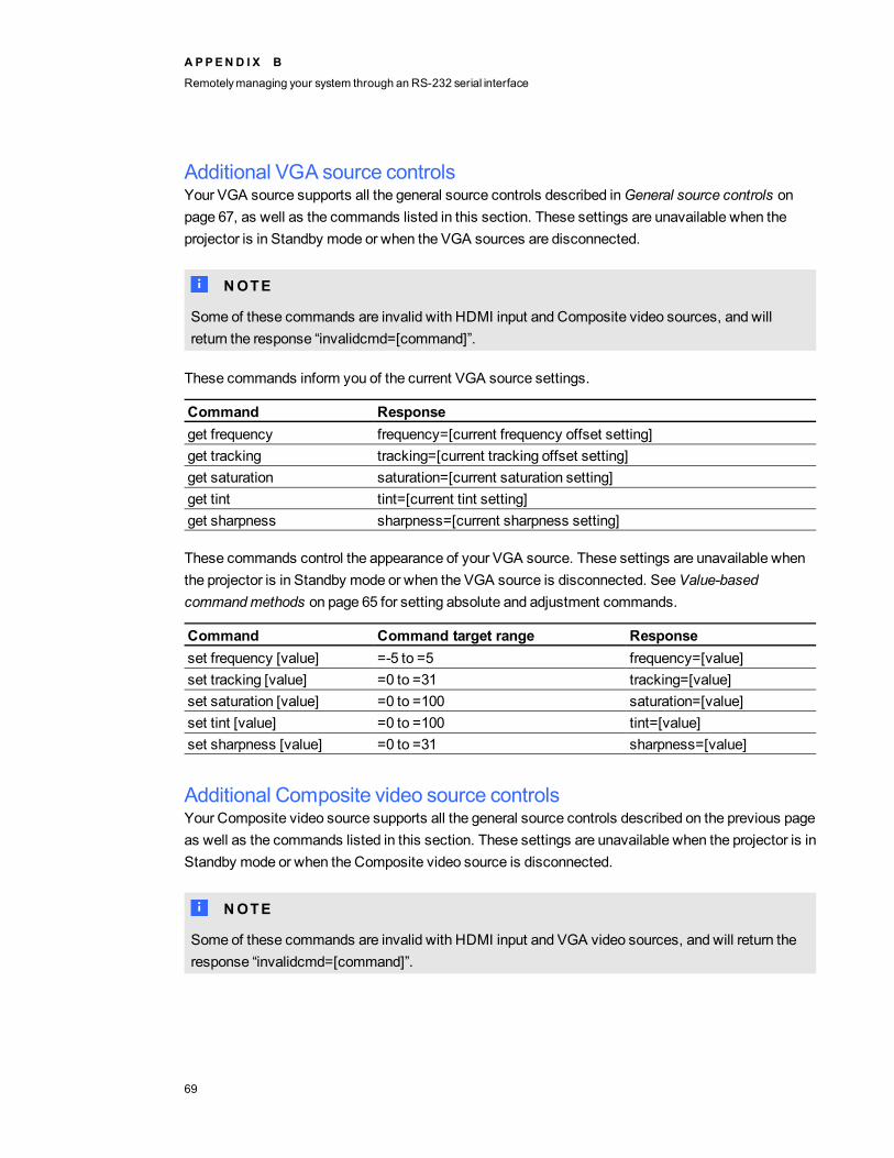
Additional VGA source controlsYour VGA source supports all the general source controls described inGeneral source controls onpage 67, as well as the commands listed in this section. These settings are unavailable when theprojector is in Standby mode or when the VGA sources are disconnected.
N NOTE
Some of these commands are invalid with HDMI input and Composite video sources, and willreturn the response “invalidcmd=[command]”.
These commands inform you of the current VGA source settings.
Command Responseget frequency frequency=[current frequency offset setting]get tracking tracking=[current tracking offset setting]get saturation saturation=[current saturation setting]get tint tint=[current tint setting]get sharpness sharpness=[current sharpness setting]
These commands control the appearance of your VGA source. These settings are unavailable whenthe projector is in Standby mode or when the VGA source is disconnected. SeeValue-basedcommandmethods on page 65 for setting absolute and adjustment commands.
Command Command target range Responseset frequency [value] =-5 to =5 frequency=[value]set tracking [value] =0 to =31 tracking=[value]set saturation [value] =0 to =100 saturation=[value]set tint [value] =0 to =100 tint=[value]set sharpness [value] =0 to =31 sharpness=[value]
Additional Composite video source controlsYour Composite video source supports all the general source controls described on the previous pageas well as the commands listed in this section. These settings are unavailable when the projector is inStandby mode or when the Composite video source is disconnected.
N NOTE
Some of these commands are invalid with HDMI input and VGA video sources, and will return theresponse “invalidcmd=[command]”.
A PPEN D I X B
Remotelymanaging your system through an RS-232 serial interface
69
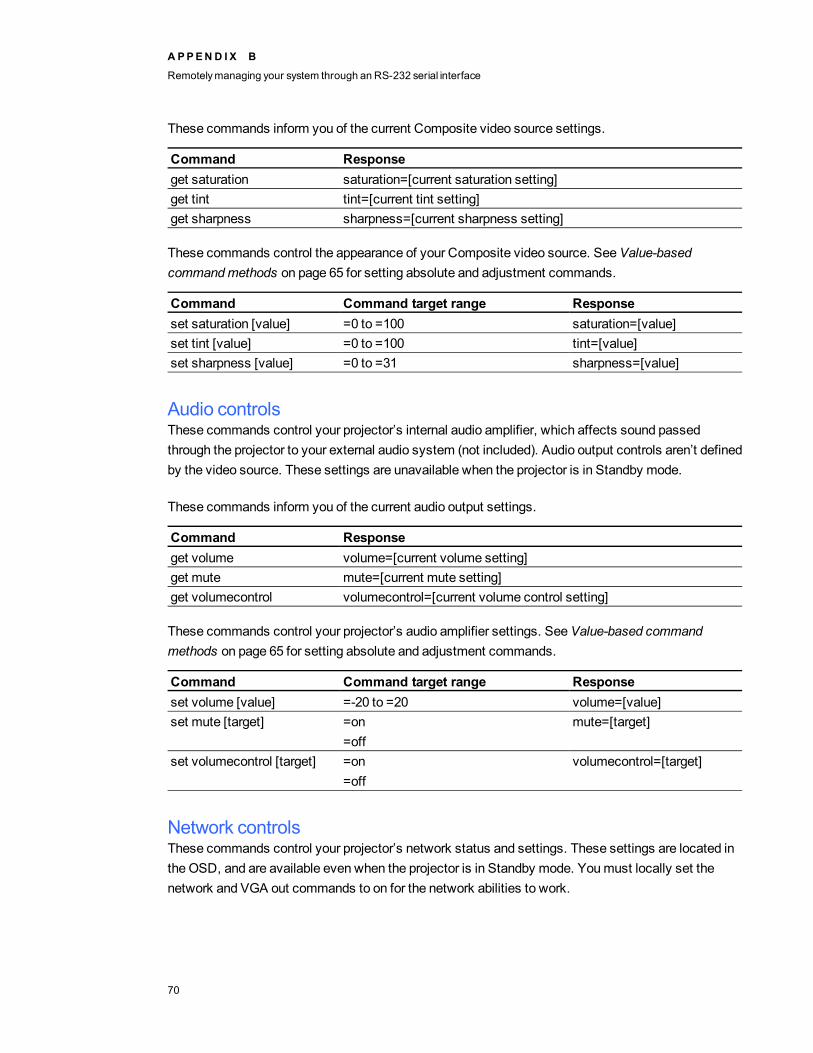
These commands inform you of the current Composite video source settings.
Command Responseget saturation saturation=[current saturation setting]get tint tint=[current tint setting]get sharpness sharpness=[current sharpness setting]
These commands control the appearance of your Composite video source. SeeValue-basedcommandmethods on page 65 for setting absolute and adjustment commands.
Command Command target range Responseset saturation [value] =0 to =100 saturation=[value]set tint [value] =0 to =100 tint=[value]set sharpness [value] =0 to =31 sharpness=[value]
Audio controlsThese commands control your projector’s internal audio amplifier, which affects sound passedthrough the projector to your external audio system (not included). Audio output controls aren’t definedby the video source. These settings are unavailable when the projector is in Standby mode.
These commands inform you of the current audio output settings.
Command Responseget volume volume=[current volume setting]get mute mute=[current mute setting]get volumecontrol volumecontrol=[current volume control setting]
These commands control your projector’s audio amplifier settings. SeeValue-based commandmethods on page 65 for setting absolute and adjustment commands.
Command Command target range Responseset volume [value] =-20 to =20 volume=[value]set mute [target] =on
=offmute=[target]
set volumecontrol [target] =on=off
volumecontrol=[target]
Network controlsThese commands control your projector’s network status and settings. These settings are located inthe OSD, and are available even when the projector is in Standby mode. Youmust locally set thenetwork and VGA out commands to on for the network abilities to work.
A PPEN D I X B
Remotelymanaging your system through an RS-232 serial interface
70
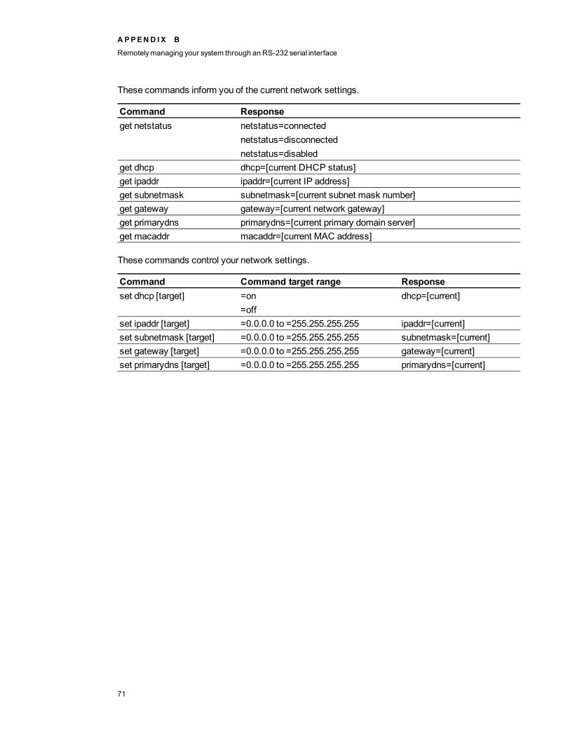
These commands inform you of the current network settings.
Command Responseget netstatus netstatus=connected
netstatus=disconnectednetstatus=disabled
get dhcp dhcp=[current DHCP status]get ipaddr ipaddr=[current IP address]get subnetmask subnetmask=[current subnet mask number]get gateway gateway=[current network gateway]get primarydns primarydns=[current primary domain server]get macaddr macaddr=[current MAC address]
These commands control your network settings.
Command Command target range Responseset dhcp [target] =on
=offdhcp=[current]
set ipaddr [target] =0.0.0.0 to =255.255.255.255 ipaddr=[current]set subnetmask [target] =0.0.0.0 to =255.255.255.255 subnetmask=[current]set gateway [target] =0.0.0.0 to =255.255.255.255 gateway=[current]set primarydns [target] =0.0.0.0 to =255.255.255.255 primarydns=[current]
A PPEN D I X B
Remotelymanaging your system through an RS-232 serial interface
71

System controlsThese commands enable you to switch system settings and access system information.
These commands inform you of the current system settings. These commands are unavailable whenthe projector is in Standby mode.
Command Responseget autosignal autosignal=[current auto signal detection setting]get lampreminder lampreminder=[current lamp reminder setting]get highbrightness highbrightness=[current lamp brightness setting]get autopoweroff autopoweroff=[current auto power off setting]get zoom zoom=[current zoom setting]get projectorid projectorid=[current projector ID number]get hposition hposition=[current horizontal position offset setting]get vposition vposition=[current vertical position offset setting]get aspectratio aspectratio=[current projector aspect ratio]get projectionmode projectionmode=[current projectionmode]get startupscreen startupscreen=[current startup screen setting]get resolution resolution=[current input resolution]get language language=[current language setting]get groupname groupname=[current projector group name]get projectorname projectorname=[current projector name]get locationinfo locationinfo=[current projector location]get contactinfo contactinfo=[current support contact information]get modelnum modelnum=[current model number]get videomute videomute=[current videomute setting]get serialnum serialnum=[serial number]
A PPEN D I X B
Remotelymanaging your system through an RS-232 serial interface
72

These commands inform you of the current system settings. These commands are available evenwhen the projector is in Standby mode.
Command Responseget lamphrs lamphrs=[current lamp hours of operation]get syshrs syshrs=[current projector hours of operation]get fwverddp fwverddp=[current projector firmware version]get fwvernet fwvernet=[current network firmware version]get fwvermpu fwvermpu=[current processor firmware version]get fwverecp fwverecp=[current ECP firmware version]get vgaoutnetenable vgaoutnetenable=[current]get signaldetected signaldetected=[true or false]get usb1source usb1source=[Video source associated with the USB 1 connector on
the ECP]get usb2source usb2source=[Video source associated with the USB 2 connector on
the ECP]
T T I P
The get usb1source and get usb2source commands are only applicable to SMART UX60projectors running DLP firmware version 1.0.0.4 or later.
These commands control the current system settings. These commands are unavailable when theprojector is in Standby mode. SeeValue-based commandmethods on page 65 for setting absoluteand adjustment commands.
Command Command target range Responseset autosignal [target] =on
=offautosignal=[target]
set lampreminder [target] =on=off
lampreminder=[target]
set highbrightness [target] =on=off
highbrightness=[target]
set autopoweroff [value] =0 to =240 autopoweroff=[value]set zoom [value] =0 to =30 zoom=[value]set projectorid [value] =0 to =99 projectorid=[value]set hposition [value] =0 to =100 hposition=[value]set vposition [value] =-5 to =5 vposition=[value]set aspectratio [target] =fill
=match=16:9
aspectratio=[target]
A PPEN D I X B
Remotelymanaging your system through an RS-232 serial interface
73

Command Command target range Responseset projectionmode [target] =front
=ceiling=rear=rear ceiling
projectionmode=[target]
set startupscreen [target] =smart=usercapture=preview
startupscreen=[target]
set language [target] =Chinese (Simplified)=Chinese (Traditional)=Czech=Danish=Dutch=English=Finnish=French=German=Greek=Italian=Japanese=Korean=Norwegian=Polish=Portuguese (Brazil)=Portuguese (Portugal)=Russian=Spanish=Swedish
language=[target]
set groupname [description] Enter a descriptor nomorethan 12 characters long.
groupname=[description]
set projectorname [description] Enter a descriptor nomorethan 12 characters long.
projectorname=[description]
set locationinfo [description] Enter a descriptor nomorethan 16 characters long.
locationinfo=[description]
set contactinfo [description] Enter a descriptor nomorethan 16 characters long.
contactinfo=[description]
set videomute [target] =on=off
videomute=[target]
A PPEN D I X B
Remotelymanaging your system through an RS-232 serial interface
74

These commands control the current system settings. These commands are available when theprojector is in Standby mode and when it is on.
Command Command target range Responseset restoredefaults [none] restoredefaults=doneset lamphrs [target] =0 lamphrs=0set vgaoutnetenable [target] =on
=offvgaoutnetenable=[target]
set usb1source [target] =vga1=vga2=hdmi=disabled
usb1source=[target]
set usb2source [target] =vga1=vga2=hdmi=disabled
usb1source=[target]
T T I P
The set usb1source and set usb2source commands are only applicable to SMART UX60projectors running DLP firmware version 1.0.0.4 or later.
N NOTE
TheNetwork and VGA Out setting’s features are off by default. Select on to activate thesefeatures.
A PPEN D I X B
Remotelymanaging your system through an RS-232 serial interface
75


Appendix C: Disabling user USB accessIn some situations, youmight want to disable the ECP’s front USB receptacle. Disabling the USBreceptacle prevents users from using or saving documents to USB drives using the ECP’s front USBreceptacle. The other USB receptacles won’t be deactivated since they’re required for yourinteractive whiteboard and computer connections to function.
Follow these instructions to remove and cut the case on the ECP, and then remove the USB jumperswitch to disable the ECP’s USB receptacle.
C CAUT ION
Always use an anti-static wrist wrap when working on the ECP.
I I MPORTANT
Do not perform this operation if you are unfamiliar with using jumper switches.
You require a Phillips No. 2 screwdriver, a pair of wire cutters and a pair of needle-nose pliers toperform the following procedure.
g To remove and cut the case on the ECP
1. Put the projector into Standby mode, and then wait 15minutes for it to cool down.
2. Disconnect the projector’s power cable from the power outlet.
3. While holding the ECP to prevent it from falling, use a Phillips No. 2 screwdriver to remove thetwo screws from the bottom of the ECP. Place the screws in a safe place.
Appendix C
77
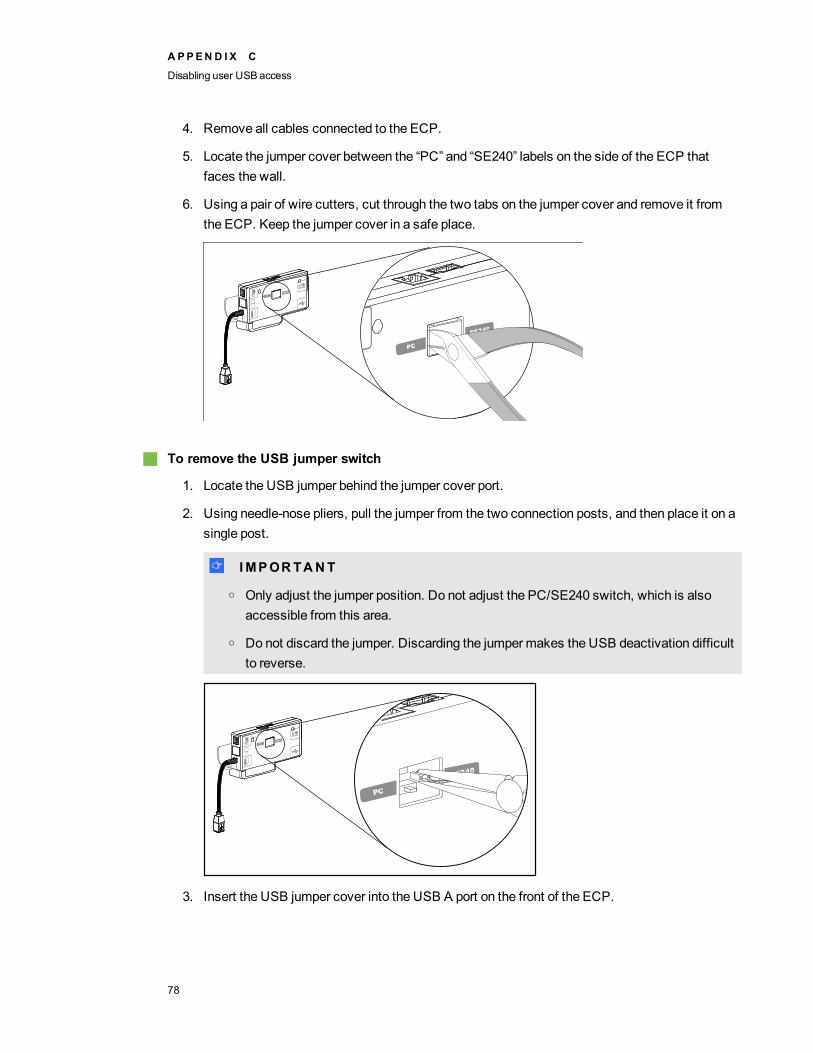
4. Remove all cables connected to the ECP.
5. Locate the jumper cover between the “PC” and “SE240” labels on the side of the ECP thatfaces the wall.
6. Using a pair of wire cutters, cut through the two tabs on the jumper cover and remove it fromthe ECP. Keep the jumper cover in a safe place.
g To remove the USB jumper switch
1. Locate the USB jumper behind the jumper cover port.
2. Using needle-nose pliers, pull the jumper from the two connection posts, and then place it on asingle post.
I I MPORTANT
o Only adjust the jumper position. Do not adjust the PC/SE240 switch, which is alsoaccessible from this area.
o Do not discard the jumper. Discarding the jumpermakes the USB deactivation difficultto reverse.
3. Insert the USB jumper cover into the USB A port on the front of the ECP.
A PPEN D I X C
Disabling user USBaccess
78

4. Connect all cables to the ECP. See theUsing the Extended Control Panel (ECP) on page 24for more information.
5. Secure the ECP to your interactive whiteboard with the two screws you removed previously.
6. Connect the projector’s power cable to the power outlet.
A PPEN D I X C
Disabling user USBaccess
79

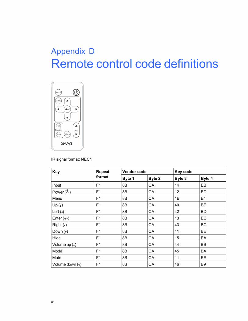
Appendix D: Remote control code definitions
IR signal format: NEC1
Key Repeatformat
Vendor code Key codeByte 1 Byte 2 Byte 3 Byte 4
Input F1 8B CA 14 EB
Power ( ) F1 8B CA 12 EDMenu F1 8B CA 1B E4Up ( ) F1 8B CA 40 BFLeft ( ) F1 8B CA 42 BDEnter ( ) F1 8B CA 13 ECRight ( ) F1 8B CA 43 BCDown ( ) F1 8B CA 41 BEHide F1 8B CA 15 EAVolume up ( ) F1 8B CA 44 BBMode F1 8B CA 45 BAMute F1 8B CA 11 EEVolume down ( ) F1 8B CA 46 B9
Appendix D
81


Appendix E: Hardware environmentalcomplianceSMART Technologies supports global efforts to ensure that electronic equipment is manufactured,sold and disposed of in a safe and environmentally friendly manner.
Waste Electrical and Electronic Equipmentregulations (WEEE directive)Waste Electrical and Electronic Equipment regulations apply to all electrical and electronic equipmentsold within the European Union.
When you dispose of any electrical or electronic equipment, including SMART Technologiesproducts, we strongly encourage you to properly recycle the electronic product when it has reachedthe end of its life. If you require further information, please contact your reseller orSMART Technologies for information on which recycling agency to contact.
Restriction of Certain Hazardous Substances(RoHS directive)This product meets the requirements of the European Union’s Restriction of Certain HazardousSubstances (RoHS) directive 2002/95/EC.
Consequently, this product also complies with other regulations that have arisen in variousgeographical areas, and that reference the European Union’s RoHS directive.
BatteriesBatteries are regulated in many countries. Check with your reseller to find out how to recycle usedbatteries.
There are special regulations that must bemet when shipping a product that has a lithium ion batterypackaged with the product or shipping a lithium ion battery. When returning a SMART Technologies
Appendix E
83

product which contains a lithium ion battery or returning a lithium ion battery, callSMART Technologies RMA for information on the special shipping regulations.
l 1.866.518.6791, Option 4 (U.S./Canada)
l 1.403.228.5940 (all other countries)
PackagingMany countries have regulations restricting the use of certain heavy metals in product packaging. Thepackaging used by SMART Technologies to ship products complies with applicable packaging laws.
China’s Electronic Information ProductsregulationsChina regulates products that are classified as EIP (Electronic Information Products).SMART Technologies products fall under this classification andmeet the requirements for China’sEIP regulations.
For more information, see smarttech.com/compliance.
A PPEN D I X E
Hardware environmental compliance
84

33.5mm audio connectors 23
Aaccessoriesincluded 5optional 6
aspect ratios 27-29, 56audioconnections for 23controlling volume of 25, 55, 70muting 13, 70resolving issues with 49
Bbatteries 12, 83
CChinese regulations 84closed captioning 55, 68composite video connections 29, 67, 69connection diagramsECP 25projector 22
contact person 58
DDHCP 57, 71display modes 55DNS 58, 71
dust vi
Ee-mail alerts 59ECPabout 4disabling USB communications for 77lights and status of 50using 24
EIP regulations 84electrostatic discharge viemissions vienvironmental requirements vieraser 6European Union regulations 83
Ffans 44, 56flickering 47focus 21
HHD signal compatibility 29HDMI connections 23, 67head space clearance 8height 8Help button 24humidity vi
Iimagefocusing 21
Index
85

resolving issues with 46input selection 25, 57, 67installationchoosing a height 8choosing a location 7
interactive whiteboardabout 2indicators and controls of 43maintaining 31using 24
IP address 57, 71
Llampmodulecleaning 31replacing 33resolving issues with 45
languages 55laptop computerstroubleshooting issues with 48
letterboxing 28-29light sources 7lithium ion batteries 83location 7, 58
MMAC address 71MAC support 28mounting template 8mute control 13, 70
Nnative video formats 27network communication 23, 49, 57, 70
Ooptions 6original packaging 51
Ppackaging 84passwords 50, 59pen trayabout 3locking to the interactive whiteboard 9
pens 5peripheral sources 30pillarboxing 28-29power 23, 25, 54, 64, 66projectorabout 3adjusting settings for 14cleaning 31connection diagram for 22displaying the name of 58focusing the image of 21installing 7lights and status of 40locating the serial number on 40remotely managing 53, 61replacing the lamp of 33routing cables from 8troubleshooting 44using your remote control with 11video format compatibility for 27
Qquad VGA support 28
RRCA jacks 23, 25refresh rates 27-28remote controlabout 5code definitions for 81installing the battery 12using the buttons 13
RJ45 connector 23
I N D EX
86
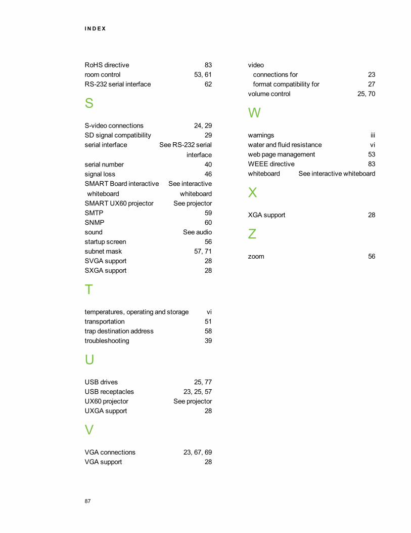
RoHS directive 83room control 53, 61RS-232 serial interface 62
SS-video connections 24, 29SD signal compatibility 29serial interface See RS-232 serial
interfaceserial number 40signal loss 46SMART Board interactivewhiteboard
See interactivewhiteboard
SMART UX60 projector See projectorSMTP 59SNMP 60sound See audiostartup screen 56subnet mask 57, 71SVGA support 28SXGA support 28
Ttemperatures, operating and storage vitransportation 51trap destination address 58troubleshooting 39
UUSB drives 25, 77USB receptacles 23, 25, 57UX60 projector See projectorUXGA support 28
VVGA connections 23, 67, 69VGA support 28
videoconnections for 23format compatibility for 27
volume control 25, 70
Wwarnings iiiwater and fluid resistance viweb pagemanagement 53WEEE directive 83whiteboard See interactive whiteboard
XXGA support 28
Zzoom 56
I N D EX
87


SMART Technologies
smarttech.com/support
smarttech.com/contactsupport