Embed Size (px)
Citation preview
Small Wind Turbine Systems for Battery Charging
SMALL WIND TURBINE SYSTEMS FOR BATTERY CHARGING
Ir. G.J. Jacobs, editor, ARRAKIS
Co-authors: Ir. J.A. de Jongh, ARRAKIS
Ir. R.P.P. Rijs, ARRAKIS Ir. J. T.G. Pierik, ECN
Copyright ARRAKIS
ARRAKIS
De Olieslager 7 5506 ER Veldhoven
The Netherlands Tel: +31-40-2819 454 Fax: +31-40-2819 602
E-mail: [email protected]: www.arrakis.nl
The Implementation of Wind Energy 1

Small Wind Turbine Systems for Battery Charging
2 The Implementation of Wind Energy
Small Wind Turbine Systems for Battery Charging
Contents Summary .........................................................................................................................................5 1 Introduction .................................................................................................................................5 2 Applications ................................................................................................................................6 3 Wind Turbine Components .........................................................................................................7
3.1 Rotor....................................................................................................................................7 3.2 Generator.............................................................................................................................8 3.3 Control and safety system ...................................................................................................9 3.4 Tower ................................................................................................................................11
4 Equipment for Stand Alone Operation......................................................................................12
4.1 Introduction .......................................................................................................................12 4.2 Functioning of batteries.....................................................................................................12 4.3 Battery voltage and capacity .............................................................................................13 4.4 Battery charge control .......................................................................................................13
5 System Sizing............................................................................................................................14
5.1 Energy demand..................................................................................................................14 5.2 Energy supply....................................................................................................................15 5.3 Size of the battery bank.....................................................................................................18
6 Economics .................................................................................................................................20 7 Technology and Product Assessment........................................................................................20
7.1 Product information...........................................................................................................20 7.2 Selection process ...............................................................................................................21 7.3 The best choice? ................................................................................................................22
References .....................................................................................................................................23 Appendix 1 Exercises.................................................................................................................24 Appendix 2 Telephone and Fax Numbers of Wind Turbine Manufacturers..............................25
The Implementation of Wind Energy 3

Small Wind Turbine Systems for Battery Charging
4 The Implementation of Wind Energy
Small Wind Turbine Systems for Battery Charging
Summary
The main objective of this contribution is to provide criteria for the selection of small wind turbines. Small wind turbines for electricity production, also referred to as wind generators1,with a capacity of less than 10 kW, are primarily used as battery chargers on locations without electricity grid. Applications can be energy supply for houses (lighting, TV, refrigerator), offices, hospitals and farms (water delivery, electrical fencing). Other applications are telecommunication and navigation. The technology of small wind turbines differs on a number of aspects from the technology of large turbines and is discussed in this contribution. Small wind turbine systems typically operate in a stand-alone mode, sometimes in parallel with diesel sets or PV systems. Since most of the time there is a mismatch between available wind power and user demand, there is a need for energy storage. The most common storage option, batteries, is discussed and a method for system sizing is provided. Batteries, electronics and control systems are critical components regarding the system reliability and lifetime. The costs of the generated electricity is very dependent on the system size, but data to estimate the cost-effectiveness of installed small wind turbine systems is not readily available. Generally, the relative investment cost (cost per square meter rotor area) decreases with increasing turbine size. In future, mass production is expected to reduce equipment costs.
1 Introduction Small wind turbines for electricity production are primarily used in stand-alone operation (viz. not grid connected) as battery chargers, in which case they are also called “wind chargers”. The rotor diameters range from about 0.5 m to about 7 m, with rated powers of about 40 Watts up to about 10 kW at 10 m/s wind speed. World wide there are about 50 manufacturers of small wind turbines, concentrated in the USA, China, Japan, Germany, France and the United Kingdom. Most of them deliver to a selected home market, though an increasing number have dealers in other countries. Some of the major manufacturers such as Bergey (USA), LMW (NL), and Marlec (UK) have established co-operation with manufacturers abroad. Modern small wind turbines typically have an upwind rotor, directly coupled (without a gearbox) to an electrical generator. Most of them have a mechanism to limit the rotor speed and the forces on the rotor at high wind speeds. The rotor speed is usually allowed to vary with the wind speed. In the past, small wind turbines were often equipped with a DC-generator. Nowadays almost all machines are equipped with alternating current (AC) generators, which supply an electric output with variable voltage and variable frequency. In stand-alone systems the chance of a mismatch between available wind power and user demand is very high. Therefore most systems are equipped with a storage device, in most cases a battery. The battery is charged and discharged depending on wind power availability and user demand. Batteries are sensitive to maintenance and proper operation.The AC-generator output is usually rectified to direct current (DC) required by the batteries. Common DC voltages are 12, 24 or 48 Volt. Larger systems may include an inverter to supply AC current for standard home 1 In this contribution the term wind turbine is used, the term generator will be reserved for an electrical generator.
The Implementation of Wind Energy 5
Small Wind Turbine Systems for Battery Charging
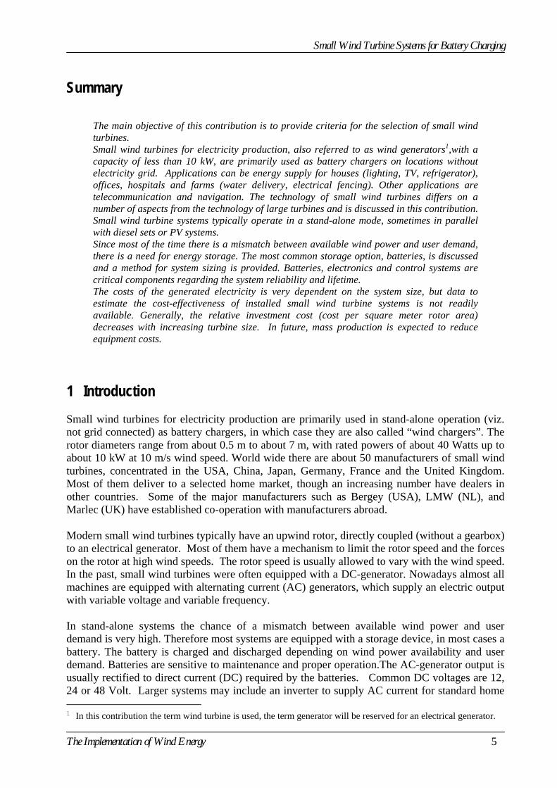
appliances (110/220 V, 50/60 Hz) or have the option to connect appliances directly to the AC-generator of the turbine. In that case the voltage and frequency of the AC-generator need to be controlled. Figure 1 gives the general lay-out of a small stand-alone wind turbine system with turbine, rectifier with charge controller, battery and DC-consumers.
Figure 1 General lay-out of a small stand-alone wind turbine system
2 Applications Small wind turbines can be found among a broad range of users. In China and the USA, they are most commonly used for domestic energy supply, lighting, radio, TV, etc. In Europe, where the penetration of the utility grid is very high, there exists a market in the tourist industry, i.e. for use on boats, campers, etc. [1]. They also find application in telecommunication systems. A list of applications is given in Table 1.
Table 1 List of applications of small wind turbines
Operation Application
Domestic power Remote homes, farms offices, hospitals Applications: Lighting, TV, radio, refrigerator, etc.
Telecommunications Rural radio systems Small telephone systems
Agriculture Water pumping; Refrigeration systems Heating; Pond Aeration Electric fencing
Navigation Light or radio beacons Offshore platform Cathodic protection Village electrification Street light Pleasure craft and boats Power supply
6 The Implementation of Wind Energy
Small Wind Turbine Systems for Battery Charging
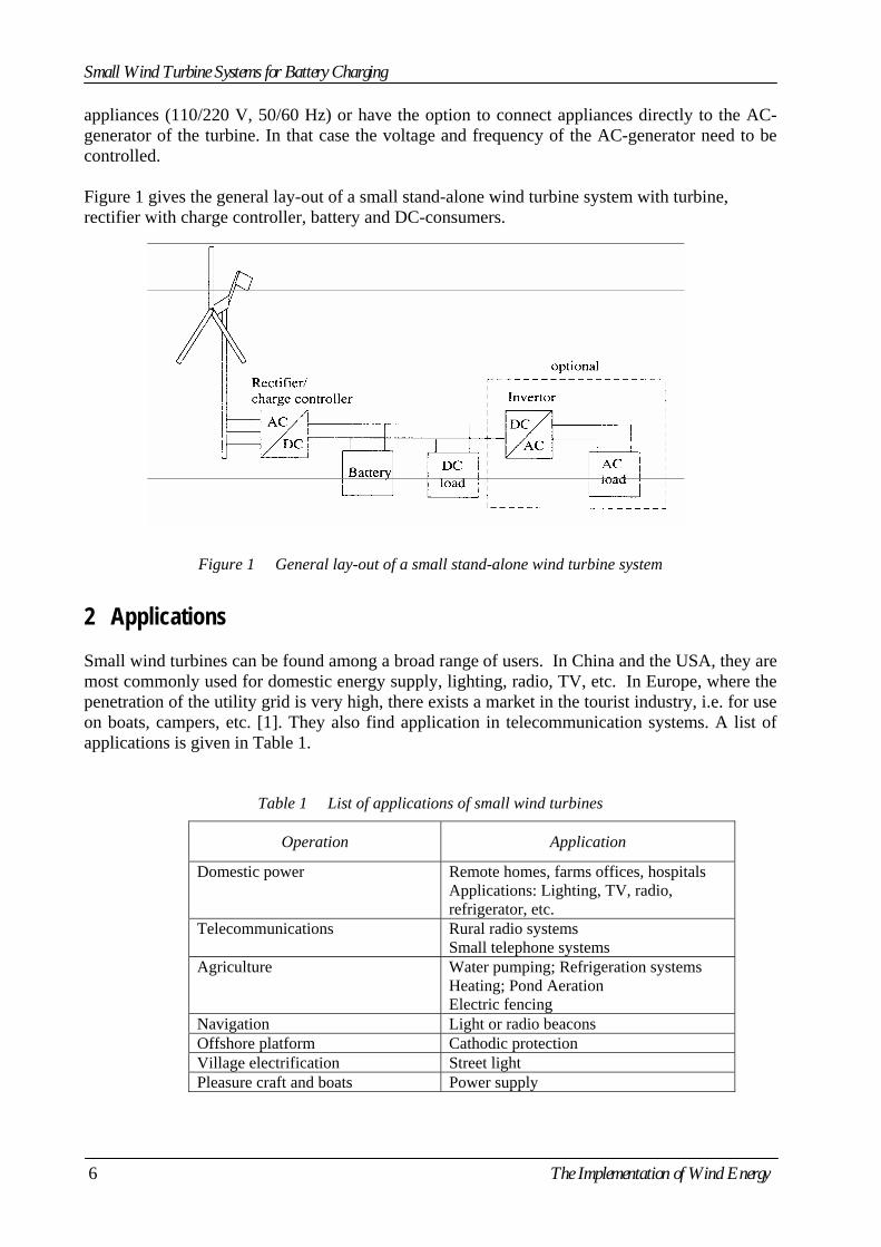
Small wind turbines can be an interesting option for small-scale energy supply at remote sites where no grid electricity is available and a grid extension would be too costly (e.g. for remote villages or homes). As such, they may have great potential in developing countries. The most striking example is probably their dissemination among the nomads in Inner Mongolia (China), where over 100,000 small portable wind turbines (capacity about 100 W) are in use for 'domestic' power supply. These wind chargers are portable. The number of small wind turbines in use world-wide is estimated at more than 200,000. Figure 2 gives some examples of different designs.
Windseeker Air 300 Rutland 913 Ampair 100
Figure 2 Examples of small wind turbines
3 Wind Turbine Components This chapter gives an overview of the different components of a small wind turbine. The aim of this section is to provide more insight in the various technical solutions applied in these systems, which forms the basis for product evaluation. 3.1 Rotor The smallest wind turbines, such as the Ampair 100 and the Rutland Windcharger (diameter about 1 meter) typically have six, fixed pitch blades of a thermoplastic material. Larger types typically have 2 or 3 blades that can be made of different materials: glass or carbon fibre reinforced epoxy or polyester, extruded aluminium alloys, steel or wood. Rotor blades are usually furnished with one or more coatings (epoxy, polyethylene, aluminium paint) to protect them against weather influences. The rotor of a small turbine is often constructed stronger than required from a static strength and fatigue point of view. Airfoils can be classified as true and single-surface airfoils. True airfoil sections have the appearance of an aircraft wing: curved on the upper side and more or less flat on the lower side. Single-surface sections have identical curves on both sides or are just flat plates. True airfoils perform better regarding power output and are less noisy, while single-surface sections are cheaper to manufacture. Profiles are usually derived from simple, well known airfoil series such
The Implementation of Wind Energy 7
Small Wind Turbine Systems for Battery Charging
as NACA 4412. Blades can either be stiff and thick, which asks for true airfoils to be used, or flexible and thin, allowing the use of simple single-section airfoils. An example is the Bergey (BWC) rotor blade composed of fibreglass reinforced plastic pultrusions. A pultrusion is a constant cross section structural product that is manufactured in a continuous moulding process, in which fibreglass strands and cloth are fed into a resin bath and then into a heated die. The cavity of the die has the finished shape of the wind turbine blade. The blades can easily be cut to different lengths to accommodate different wind speed sites. 3.2 Generator Wind turbines are equipped with a device to convert mechanical power into electric power: an electric generator. The basic concepts behind a generator are the phenomena that an electric current is induced in a copper wire in a moving magnetic field (Lorentz's Law) and that a force is exerted on a current conducting wire in a stationary magnetic field. The classical electric generator is the direct current (DC) generator. Copper wiring is mounted on a rotating shaft (the "rotor"), while the magnetic field is provided by an electromagnet in the "stator", fixed to the generator housing. When the rotor is moved by an external force, a current flows in the rotor and an electromagnetic force counteracts the external force. DC generators have brushes that wear causing maintenance. Although in early days of development of small wind turbines DC generators were used, presently they are used very occasionally because of this reason. Small wind turbines are equipped mostly with an AC-generator. There are three different types of AC-generators: the synchronous generator (also referred to as alternator), the asynchronous or induction generator and the permanent magnet generator. In the early days, car alternators were applied in small wind turbines. However, car alternators have not been developed for continuous operation over a long period of time and have caused problems when used in small wind turbines. Industrial synchronous generators (SG) are not used often in wind turbines under 10 kW, simply because they are hardly available in this low power range. Asynchronous generators (AG) require some additional measures to operate independently from the utility grid, which make them less economical for the small wind turbines. They are commonly used in grid connected wind turbines of 25 kW and more. Poor field excitation in alternators at low speed is another problem. Since the induced field voltage is proportional to the product of magnetic flux and speed, the induced currents are small at low speed. The permanent magnet generator is the type of generator most used for wind-chargers nowadays. Permanent magnet generators (PMG) have a constant magnetic field. They give higher output currents at low speeds, but at high speeds the field flux is weaker than of an electrically excited machine, unless special but expensive magnetic materials are used. An additional advantage of the PMG is that it can be used as an electrical brake to stop the wind rotor by short-circuiting the generator terminals. Its efficiency is also high . The asynchronous generator and the permanent magnet generator with magnets on the rotor have no brushes, and therefore require hardly any maintenance. One problem of using a generator coupled to a turbine rotor is the difference in design speed. Small wind turbines run for instance at 300 rpm (dependent on the rotor size, the number of blades and the blade profile), while standard industrial AC-generators run at 1,500 or 3,000 rpm, depending on the number of pole pairs. The generator speed is essential for the correct voltage and power level. A gearbox is needed to make both devices (turbine rotor and generator) run at
8 The Implementation of Wind Energy
Small Wind Turbine Systems for Battery Charging
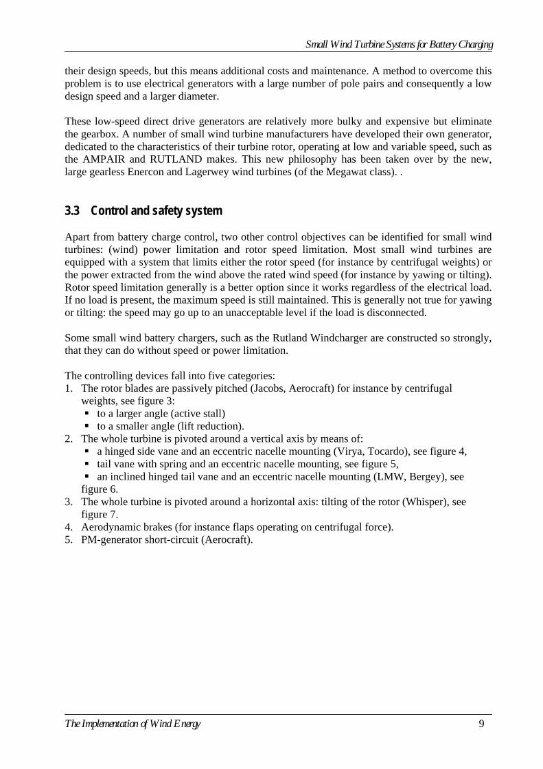
their design speeds, but this means additional costs and maintenance. A method to overcome this problem is to use electrical generators with a large number of pole pairs and consequently a low design speed and a larger diameter. These low-speed direct drive generators are relatively more bulky and expensive but eliminate the gearbox. A number of small wind turbine manufacturers have developed their own generator, dedicated to the characteristics of their turbine rotor, operating at low and variable speed, such as the AMPAIR and RUTLAND makes. This new philosophy has been taken over by the new, large gearless Enercon and Lagerwey wind turbines (of the Megawat class). . 3.3 Control and safety system Apart from battery charge control, two other control objectives can be identified for small wind turbines: (wind) power limitation and rotor speed limitation. Most small wind turbines are equipped with a system that limits either the rotor speed (for instance by centrifugal weights) or the power extracted from the wind above the rated wind speed (for instance by yawing or tilting). Rotor speed limitation generally is a better option since it works regardless of the electrical load. If no load is present, the maximum speed is still maintained. This is generally not true for yawing or tilting: the speed may go up to an unacceptable level if the load is disconnected. Some small wind battery chargers, such as the Rutland Windcharger are constructed so strongly, that they can do without speed or power limitation. The controlling devices fall into five categories: 1. The rotor blades are passively pitched (Jacobs, Aerocraft) for instance by centrifugal
weights, see figure 3: to a larger angle (active stall) to a smaller angle (lift reduction).
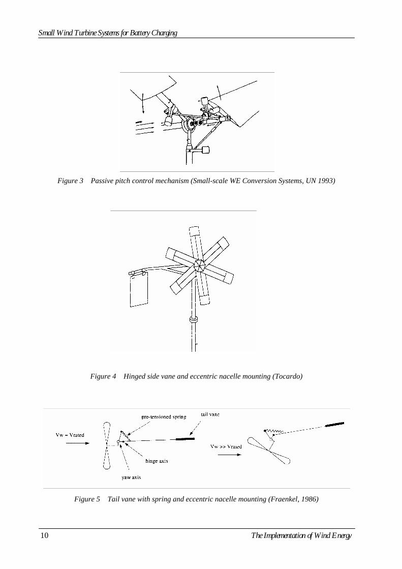
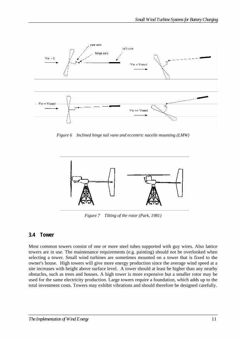
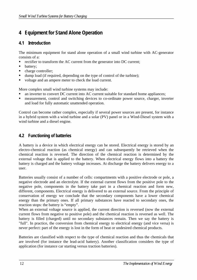
2. The whole turbine is pivoted around a vertical axis by means of: a hinged side vane and an eccentric nacelle mounting (Virya, Tocardo), see figure 4, tail vane with spring and an eccentric nacelle mounting, see figure 5, an inclined hinged tail vane and an eccentric nacelle mounting (LMW, Bergey), see
figure 6. 3. The whole turbine is pivoted around a horizontal axis: tilting of the rotor (Whisper), see
figure 7. 4. Aerodynamic brakes (for instance flaps operating on centrifugal force). 5. PM-generator short-circuit (Aerocraft).
The Implementation of Wind Energy 9
Small Wind Turbine Systems for Battery Charging
Figure 3 Passive pitch control mechanism (Small-scale WE Conversion Systems, UN 1993)
Figure 4 Hinged side vane and eccentric nacelle mounting (Tocardo)
Figure 5 Tail vane with spring and eccentric nacelle mounting (Fraenkel, 1986)
10 The Implementation of Wind Energy
Small Wind Turbine Systems for Battery Charging
Figure 6 Inclined hinge tail vane and eccentric nacelle mounting (LMW)
Figure 7 Tilting of the rotor (Park, 1981) 3.4 Tower Most common towers consist of one or more steel tubes supported with guy wires. Also lattice towers are in use. The maintenance requirements (e.g. painting) should not be overlooked when selecting a tower. Small wind turbines are sometimes mounted on a tower that is fixed to the owner's house. High towers will give more energy production since the average wind speed at a site increases with height above surface level. A tower should at least be higher than any nearby obstacles, such as trees and houses. A high tower is more expensive but a smaller rotor may be used for the same electricity production. Large towers require a foundation, which adds up to the total investment costs. Towers may exhibit vibrations and should therefore be designed carefully.
The Implementation of Wind Energy 11
Small Wind Turbine Systems for Battery Charging
4 Equipment for Stand Alone Operation 4.1 Introduction The minimum equipment for stand alone operation of a small wind turbine with AC-generator consists of a: rectifier to transform the AC current from the generator into DC current; battery; charge controller; dump load (if required, depending on the type of control of the turbine); voltage and an ampere meter to check the load current.
More complex small wind turbine systems may include: an inverter to convert DC current into AC current suitable for standard home appliances; measurement, control and switching devices to co-ordinate power source, charger, inverter
and load for fully automatic unattended operation. Control can become rather complex, especially if several power sources are present, for instance in a hybrid system with a wind turbine and a solar (PV) panel or in a Wind-Diesel system with a wind turbine and a diesel engine. 4.2 Functioning of batteries A battery is a device in which electrical energy can be stored. Electrical energy is stored by an electro-chemical reaction (as chemical energy) and can subsequently be retrieved when the chemical reaction is reversed. The direction of the chemical reaction is determined by the external voltage that is applied to the battery. When electrical energy flows into a battery the battery is charged and the battery voltage increases. At discharge the battery delivers energy to a user. Batteries usually consist of a number of cells: compartments with a positive electrode or pole, a negative electrode and an electrolyte. If the external current flows from the positive pole to the negative pole, components in the battery take part in a chemical reaction and form new, different, components. Electrical energy is delivered to an external source. From the principle of conservation of energy we conclude that the secondary components have a lower chemical energy than the primary ones. If all primary substances have reacted to secondary ones, the reaction stops: the battery is “empty”. When an external voltage source is applied, the current direction is reversed (now the external current flows from negative to positive pole) and the chemical reaction is reversed as well. The battery is filled (charged) until no secondary substances remain. Then we say the battery is "full". In practice, the conversion from chemical energy to electrical energy (and vice versa) is never perfect: part of the energy is lost in the form of heat or undesired chemical products. Batteries are classified with respect to the type of chemical reaction and thus the chemicals that are involved (for instance the lead-acid battery). Another classification considers the type of application (for instance car starting versus traction batteries).
12 The Implementation of Wind Energy
Small Wind Turbine Systems for Battery Charging
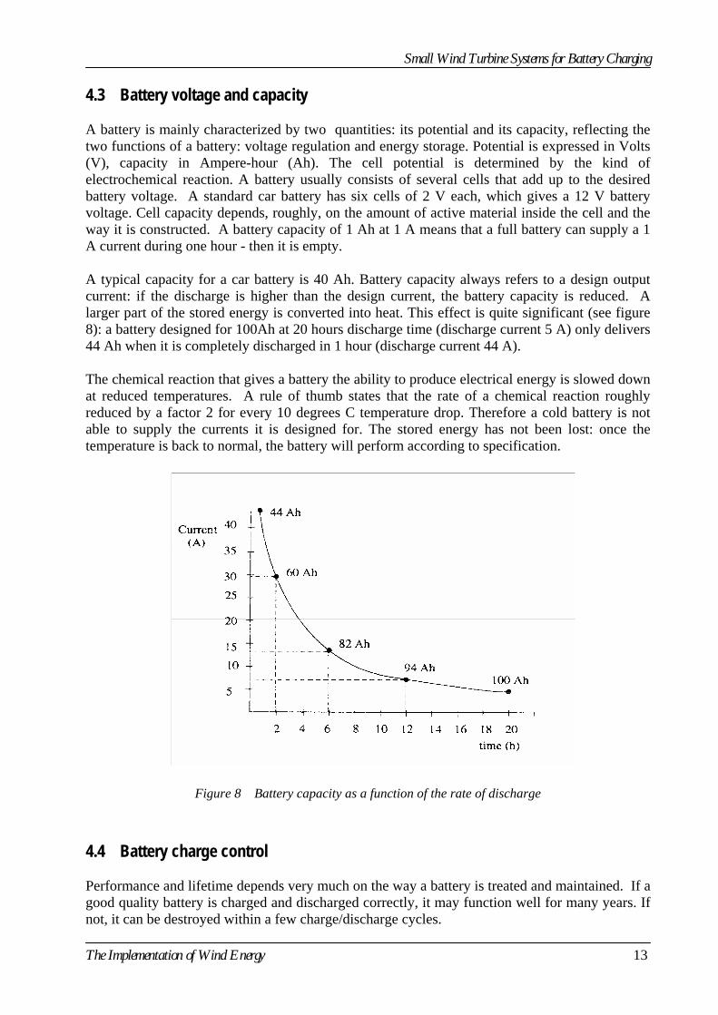
4.3 Battery voltage and capacity A battery is mainly characterized by two quantities: its potential and its capacity, reflecting the two functions of a battery: voltage regulation and energy storage. Potential is expressed in Volts (V), capacity in Ampere-hour (Ah). The cell potential is determined by the kind of electrochemical reaction. A battery usually consists of several cells that add up to the desired battery voltage. A standard car battery has six cells of 2 V each, which gives a 12 V battery voltage. Cell capacity depends, roughly, on the amount of active material inside the cell and the way it is constructed. A battery capacity of 1 Ah at 1 A means that a full battery can supply a 1 A current during one hour - then it is empty. A typical capacity for a car battery is 40 Ah. Battery capacity always refers to a design output current: if the discharge is higher than the design current, the battery capacity is reduced. A larger part of the stored energy is converted into heat. This effect is quite significant (see figure 8): a battery designed for 100Ah at 20 hours discharge time (discharge current 5 A) only delivers 44 Ah when it is completely discharged in 1 hour (discharge current 44 A). The chemical reaction that gives a battery the ability to produce electrical energy is slowed down at reduced temperatures. A rule of thumb states that the rate of a chemical reaction roughly reduced by a factor 2 for every 10 degrees C temperature drop. Therefore a cold battery is not able to supply the currents it is designed for. The stored energy has not been lost: once the temperature is back to normal, the battery will perform according to specification.
Figure 8 Battery capacity as a function of the rate of discharge
4.4 Battery charge control Performance and lifetime depends very much on the way a battery is treated and maintained. If a good quality battery is charged and discharged correctly, it may function well for many years. If not, it can be destroyed within a few charge/discharge cycles.
The Implementation of Wind Energy 13

Small Wind Turbine Systems for Battery Charging
Battery charging requires at least some control of the charge current. When the batteries are full, the current to the batteries is reduced (trickle charge or gassing) or completely switched off. More advanced systems include monitoring - to a larger or lesser extent - of the whole charging process, and protection against deep discharge. This requires an estimate of the state of charge of the batteries. This is less straight forward as it may seem: the open circuit voltage is a good indication for the state of charge but has to be estimated under operating (charge or discharge) conditions. Charge and discharge characteristics depend upon the type of battery. This makes certain types more suitable to specific applications than others. Standard car lead-acid batteries are designed to supply the high current required by the start motor. However, they are very sensitive to deep-discharging, which makes them less suitable for storage of large amounts of energy. Special deep-cycle lead-acid batteries exist, such as used in electrical cars, which are more suitable for energy storage in wind and solar energy systems. They are more expensive than car batteries, but this is partly compensated because less capacity is needed. However, in many countries car batteries will be the only affordable and available option. 5 System Sizing The process of system sizing tries to answers two questions: 1. How “big” should the wind turbine be for a certain application? 2. How many batteries should be installed? The procedures described here do not give an exact answer to these questions. Some problems with system sizing are: It is difficult to predict accurately how much electricity will be required every day
(energy demand). Often the average wind speed and wind distribution are not known for the site. It is not known how much energy a particular wind turbine will produce at a particular site
(turbine power curve and interaction with the load unknown). 5.1 Energy demand Determination of energy requirement The first step in sizing the system is to determine the daily requirement for electricity. This is based on the power rating of each appliance and the length of time it is used every day. Table 2 gives an example of a calculation.
Table 2 Calculation of daily energy consumption of a family
Appliance Rated power
(W) Hours per day in use
(hours) Energy per day
Wh/day Lights 5*20 5 500 Refrigerator 300 12 3600 Radio 25 4 100 TV 200 3 600 Total 625 4800
14 The Implementation of Wind Energy
Small Wind Turbine Systems for Battery Charging
This gives an energy consumption of 4.8 kWh/day. The energy consumption can best be given per month, since demand varies per season (month) and also because the power supplied by the wind turbine is often given per month, based on average monthly wind speeds. For this example, the average energy requirement for the month of i.e. December becomes approximately 31 days x 4.8 kWh/day ≈ 150 kWh. Determination of power requirement When the power usage by each apparatus is plotted in a graph as function of the time, say on an hour scale for one day, the maximum value of the power at a particular moment, gives the peak power. The peak power should be determined for the day of the month with the highest power requirement. A general rule for the capacity of the wind turbine is that it should not be taken significantly greater than the maximum average power requirement plus the system losses. The peak powers can be delivered by the battery bank. 5.2 Energy supply A wind turbine and batteries of sufficient quality and capacity should supply the required energy. The design of the system involves finding an optimum between costs (increasing with higher capacity and quality) and risk for shortage of energy supply. The energy output of a wind turbine can be obtained by using a: 1. generalized formula, 2. table, 3. power curve (P-v curve) and wind speed distribution. Using a generalized formula to determine energy output The long term energy output of a wind turbine can be estimated by using a rule of thumb (note that this a very rough estimate, because it does not take the turbine characteristics into account): Ean = b A vav
3
In which: Ean is the energy generated by the wind turbine during a year expressed in kWh vav average annual wind speed (m/s) A area if the wind turbine (m2) b conversion factor The value of b depends on the wind turbine design i.e. its aerodynamic efficiency and the average wind speed and wind speed distribution. At vav = 4 m/s the value of b is approximately 2. If tables or graphs of annual output in kWh against average wind speeds are given, the value of b can be calculated. This is done in table 3 below for three LMW wind turbines.
The Implementation of Wind Energy 15
Small Wind Turbine Systems for Battery Charging
Table 3 Calculation of the value of b for three LMW wind turbines (see appendix)
LMW250 LMW600 LMW1003diameter (m) 1,7 2,2 3,1Vav (m/s) kWh/year b kWh/year b kWh/year b
4 305 2,1 580 2,4 1060 2,2 5 525 1,9 975 2,1 1755 1,8 6 750 1,5 1420 1,7 2480 1,5 7 945 1,2 1855 1,4 3180 1,2 8 1105 1,0 2240 1,2 3815 1,0
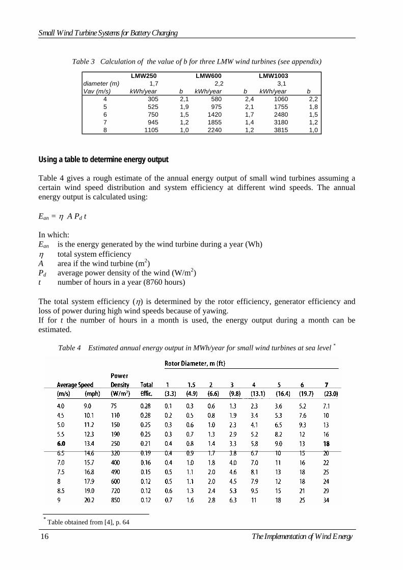
Using a table to determine energy output Table 4 gives a rough estimate of the annual energy output of small wind turbines assuming a certain wind speed distribution and system efficiency at different wind speeds. The annual energy output is calculated using: Ean = η A Pd t In which: Ean is the energy generated by the wind turbine during a year (Wh) η total system efficiency A area if the wind turbine (m2) Pd average power density of the wind (W/m2) t number of hours in a year (8760 hours) The total system efficiency (η) is determined by the rotor efficiency, generator efficiency and loss of power during high wind speeds because of yawing. If for t the number of hours in a month is used, the energy output during a month can be estimated.
Table 4 Estimated annual energy output in MWh/year for small wind turbines at sea level *
* Table obtained from [4], p. 64
16 The Implementation of Wind Energy
Small Wind Turbine Systems for Battery Charging
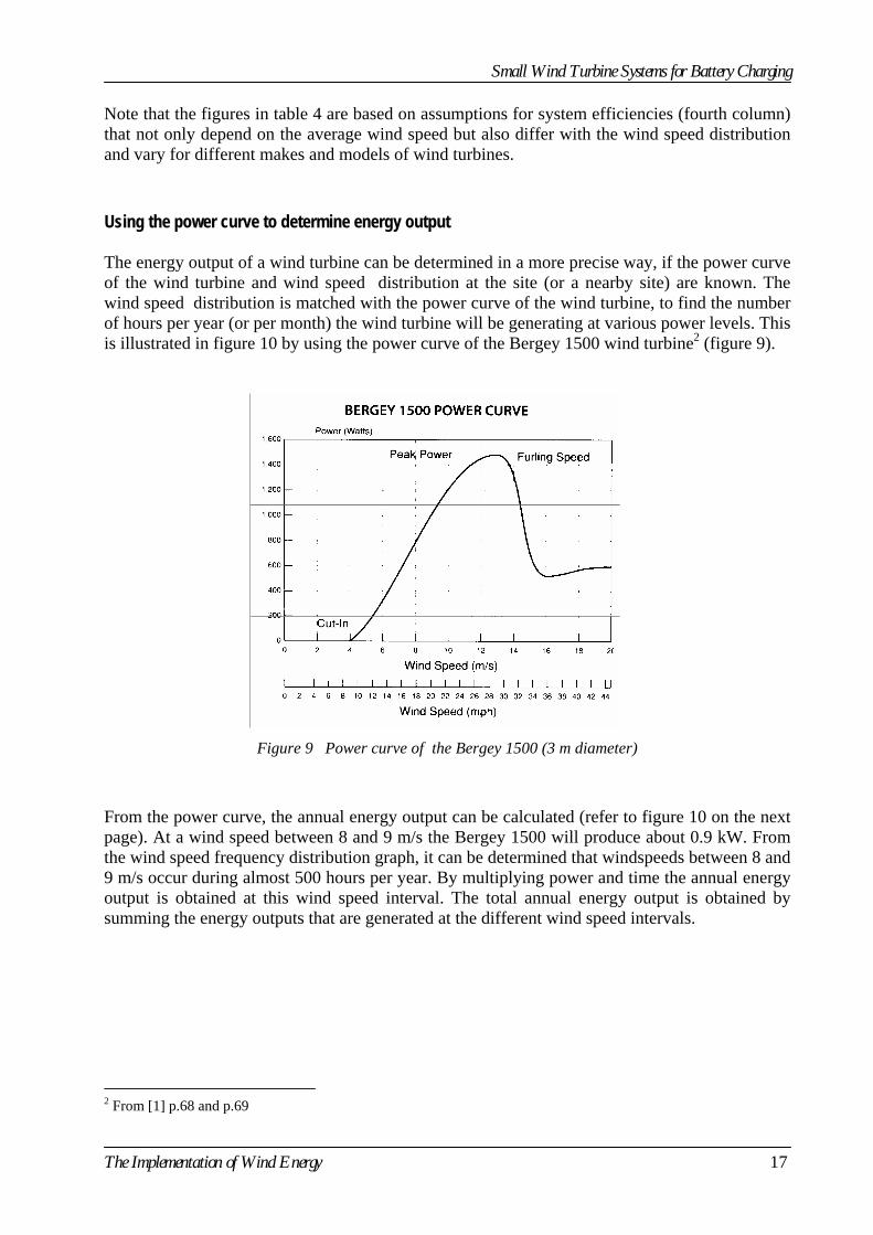
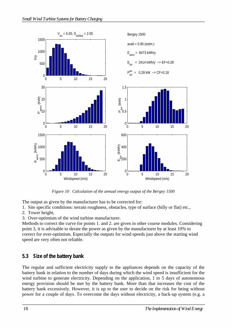
Note that the figures in table 4 are based on assumptions for system efficiencies (fourth column) that not only depend on the average wind speed but also differ with the wind speed distribution and vary for different makes and models of wind turbines. Using the power curve to determine energy output The energy output of a wind turbine can be determined in a more precise way, if the power curve of the wind turbine and wind speed distribution at the site (or a nearby site) are known. The wind speed distribution is matched with the power curve of the wind turbine, to find the number of hours per year (or per month) the wind turbine will be generating at various power levels. This is illustrated in figure 10 by using the power curve of the Bergey 1500 wind turbine2 (figure 9).
Figure 9 Power curve of the Bergey 1500 (3 m diameter)
From the power curve, the annual energy output can be calculated (refer to figure 10 on the next page). At a wind speed between 8 and 9 m/s the Bergey 1500 will produce about 0.9 kW. From the wind speed frequency distribution graph, it can be determined that windspeeds between 8 and 9 m/s occur during almost 500 hours per year. By multiplying power and time the annual energy output is obtained at this wind speed interval. The total annual energy output is obtained by summing the energy outputs that are generated at the different wind speed intervals.
2 From [1] p.68 and p.69
The Implementation of Wind Energy 17
Small Wind Turbine Systems for Battery Charging
0 5 10 15 200
500
1000
1500h
/yV
av = 5.00, S
weibul = 2.00
0 5 10 15 200
10
20
30
Paero
(kW
)
0 5 10 15 200
500
1000
1500
Eaero
(kW
h)
Windspeed (m/s)
0 5 10 15 200
0.5
1
1.5
Ptu
r (kW
)
Bergey 1500
avail = 0.95 (estm.)
Eaero
= 8473 kWh/y
Etur
= 2414 kWh/y −> EF=0.28
Pturav = 0.28 kW −> CF=0.18
0 5 10 15 200
200
400
600
Windspeed (m/s)
Etu
r (kW
h)
Figure 10 Calculation of the annual energy output of the Bergey 1500
The output as given by the manufacturer has to be corrected for: 1. Site specific conditions: terrain roughness, obstacles, type of surface (hilly or flat) etc., 2. Tower height, 3. Over-optimism of the wind turbine manufacturer. Methods to correct the curve for points 1. and 2. are given in other course modules. Considering point 3, it is advisable to derate the power as given by the manufacturer by at least 10% to correct for over-optimism. Especially the outputs for wind speeds just above the starting wind speed are very often not reliable. 5.3 Size of the battery bank The regular and sufficient electricity supply to the appliances depends on the capacity of the battery bank in relation to the number of days during which the wind speed is insufficient for the wind turbine to generate electricity. Depending on the application, 1 to 5 days of autonomous energy provision should be met by the battery bank. More than that increases the cost of the battery bank excessively. However, it is up to the user to decide on the risk for being without power for a couple of days. To overcome the days without electricity, a back-up system (e.g. a
18 The Implementation of Wind Energy
Small Wind Turbine Systems for Battery Charging
petrol generator) can be used. Also the electricity demand can be decreased during periods with low wind speeds by load management (switching off lights). It is obvious that the number of days during which the windspeed does not reach the vstart of the wind turbine, is an important design parameter for determining the size of the battery bank. The size of the battery bank can be calculated using: Ebat = (1/ηbat) (1/DODmax) Ndown Edem In which: Ebat is the size of the battery bank in Wh ηbat battery efficiency which depends on the type of battery used ηbat = 0.7...0.8 for Lead-Acid batteries ηbat = 0.6...0.7 for Nickel-Cadmium batteries DODmax maximum Depth Of Discharge, expressed is a fraction of the total battery capacity Ndown design number of consecutive days the windcharger does not charge. Edem energy demand for 1 day in Wh Depending on the material and construction of the battery plates, an additional capacity should be added. Pure lead batteries often have poor cycling performance: maximum DOD is 0.2 (20%) but are capable of occasional deep discharges. The required capacity of the battery bank should be further increased due to de-rating caused by low temperature and/or self-discharge. The battery supplier should give information. When figures are not known, add at least 10% to the size of the battery bank, to compensate for these effects. To take care that the total capacity of the battery bank is sufficient to receive the maximum charging current supplied by the wind turbine, the following rule should be followed: Ebat > 10 Imax In which: Ebat is the capacity of the battery bank in Ah Imax maximum charging current (A)
The Implementation of Wind Energy 19
Small Wind Turbine Systems for Battery Charging
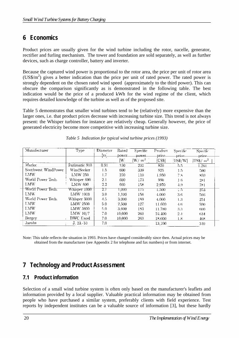
6 Economics Product prices are usually given for the wind turbine including the rotor, nacelle, generator, rectifier and furling mechanism. The tower and foundation are sold separately, as well as further devices, such as charge controller, battery and inverter. Because the captured wind power is proportional to the rotor area, the price per unit of rotor area (US$/m2) gives a better indication than the price per unit of rated power. The rated power is strongly dependent on the chosen rated wind speed (approximately to the third power). This can obscure the comparison significantly as is demonstrated in the following table. The best indication would be the price of a produced kWh for the wind regime of the client, which requires detailed knowledge of the turbine as well as of the proposed site. Table 5 demonstrates that smaller wind turbines tend to be (relatively) more expensive than the larger ones, i.e. that product prices decrease with increasing turbine size. This trend is not always present: the Whisper turbines for instance are relatively cheap. Generally however, the price of generated electricity become more competitive with increasing turbine size.
Table 5 Indication for typical wind turbine prices (1993)
Note: This table reflects the situation in 1993. Prices have changed considerably since then. Actual prices may be obtained from the manufacturer (see Appendix 2 for telephone and fax numbers) or from internet.
7 Technology and Product Assessment 7.1 Product information Selection of a small wind turbine system is often only based on the manufacturer's leaflets and information provided by a local supplier. Valuable practical information may be obtained from people who have purchased a similar system, preferably clients with field experience. Test reports by independent institutes can be a valuable source of information [3], but these hardly
20 The Implementation of Wind Energy
Small Wind Turbine Systems for Battery Charging
exist. However, there are initiatives towards certification of small wind turbines, similar to the certification of large turbines [2]. Manufacturer information tends to be optimistic with respect to the electricity production and sometimes gives output figures at unrealistic high wind speeds. Leaflets can provide a substantial amount of technical background information, which may be quite revealing to clients. Manufacturer should also provide information about warranty and after-sales services and required maintenance. Manufacturers will usually advice customers on the best system choice and will assist them to determine the correct turbine and battery size. For this purpose they need detailed information about the user's power demand. Many have standard questionnaires to be completed by the customer. 7.2 Selection process The fist step towards the determination of a suitable small wind turbine system is the determination of the requirements and boundary conditions of the potential user. These include: average power and peak power; power demand profile (representative days in different seasons); type of loads:
- DC; - AC; - sensitivity of loads to voltage and frequency changes;
average and extreme wind speed; wind speed distribution; exact location of the site; other climatological conditions:
- minimum and maximum temperature; - humidity levels; - ambient pressure; - chance of cyclones (tiltable tower);
type of operation: - fully automatic (unattended); - (partially) by hand;
available budget. Now an estimate of the required size of the turbine and the battery bank can be made. The acceptable percentage of time without power is a crucial parameter. When the system size has been determined, the available systems have to be evaluated on a number of aspects: estimated energy production of the turbine; suitability for the specific site conditions:
- survival wind speed; - climatic conditions; - transport, installation;
level of automation; is a dump load required? technical specifications of the turbine:
- blades;
The Implementation of Wind Energy 21
Small Wind Turbine Systems for Battery Charging
- control; - generator; - gearbox; - nacelle; - tower (type, height);
technical specifications of the battery: - type; - voltage; - capacity at different discharge currents;
type of rectifier/charge controller: - simple; - sophisticated;
inverter (if required); modularity (suitability for future extension); reliability of wind turbine and other system components; required maintenance; initial and maintenance costs; estimated price of one kWh; warranty; after-sales services.
7.3 The best choice? It is doubtful if there exists a best choice out of all small wind turbine systems available on the market. It is already difficult to give guidelines to lead one potential customer to his best choice. Users form a quite inhomogeneous group and have different requirements, different wind conditions and the weight attributed to the individual selection criteria may therefore differ widely. In any case, the final decision will always be a compromise. However, good support from the manufacturer is perhaps the most essential. The best choice from an economical point of view means a fast payback time. This may be calculated if the wind turbine system generates some income, as is the case for grid connected turbines. If the wind turbine is installed for domestic power supply, it is likely to improve the quality of life, but how can this be measured? For stand-alone operation no direct income is generated, but the price of electricity from a wind turbine can be compared to the price of alternative options. Sometimes wind energy can be combined with other resources into a hybrid system (such as wind-solar) to meet the needs better. System reliability depends on product quality, but also on operating conditions and maintenance. Manufacturers sometimes pretend that their products can do without maintenance - it's better not to try it out. A wind turbine is a complex device and needs to be inspected on a regular basis. Some systems need more attention than others, and it depends on the local circumstances how a given system has to be maintained. Especially for larger wind turbines and hybrid systems operation and maintenance requires skilled people. If these are not available, it is advisable to choose an alternative solution.
22 The Implementation of Wind Energy
Small Wind Turbine Systems for Battery Charging
References [1] Jeffrey, K., Independent energy Guide: Electrical Power for Home and Boat, Orwell Cove
press, Ashland, MA, USA, 1995. [2] Hulle, F.J.L. van, Soullie, P.P., Regulations for the Type Certification of Small Wind
Turbines, Technical Report ECN-R-95-020, ECN, 1995. [3] Hulle, F.J.L., Verification of Design loads of Small Wind Turbines, Technical Report ECN-
C-96-033, ECN, 1996. [4] Gipe, P., Wind Power for Home & Business, Chelsea Green Publishing Company, Vermont,
1993.
The Implementation of Wind Energy 23
Small Wind Turbine Systems for Battery Charging
Appendix 1 Exercises Exercise 1 A family has the following energy requirement: Refrigerator 200 W 10 hours per day Television 250 W 3 hours per day 4 Lights 20 W each 2 hours per day 2 Lights 15 W each 1 hour per day Radio 30 W 5 hours per day Freezer 350 W 8 hours per day
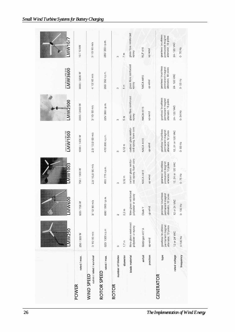
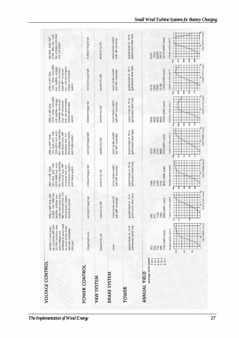
Choose a wind turbine for this system (consult the last 2 pages of this module for manufacturer information), considering an average annual wind speed of 5 m/s. Answer the same question for an average annual wind speed of 8 m/s. Determine the size of the battery bank (lead-acid and 25% maximum depth of discharge) if a total of three days of autonomy is required Exercise 2 Calculate the values of the conversion factor b (similar as in table 3), for the LMW3600 and LMW10/7, using the manufacturer information (last two pages of this module). Exercise 3 Calculate the energy output of the LMW1500 wind turbine, using the manufacturer information (last two pages of this module). Exercise 4 Calculate the internal resistance of the battery of figure 8. The battery voltage is 12 V.
24 The Implementation of Wind Energy
Small Wind Turbine Systems for Battery Charging
Appendix 2 Telephone and Fax Numbers of Wind Turbine Manufacturers
Company Country Telephone Fax
Baltaruta Bergey Windpower Fortis Windenergy Lagerwey LMW Renewables LVM Marlec North Energy Association Proven Solartechnik Geiger Soutwest Windpower Vergnet Windmission Windside Windstream
Latvia USA Netherlands Netherlands Netherlands UK UK UK UK Germany USA France Denmark Finland USA
+317 2 558711 +1 405 364 4212 +31 50 5340104 +31 342 422724 +31 342 421986 +44 1462 733336 +44 1536 201588 +44 1670 516949 +44 1563 543020 +49 8450 7390 +1 520 779 9463 +33 2 3822 7520 +45 62 1555 +385 208 350700 +1 802 658 0075
+317 2 558711 +1 405 364 2078 +31 50 5340401 +31 342 422861 +31 342 421759 +44 1462 730466 +44 1536 400211 +44 1670 510300 +44 1563 539119 +49 8450 7390 +1 520 779 1485 +33 2 3822 7522 +45 62 1555 +385 208 350700 +1 802 658 1098
The Implementation of Wind Energy 25
Small Wind Turbine Systems for Battery Charging Small Wind Turbine Systems for Battery Charging
26 The Implementation of Wind Energy
26 The Implementation of Wind Energy
Small Wind Turbine Systems for Battery Charging Small Wind Turbine Systems for Battery Charging
The Implementation of Wind Energy 27
The Implementation of Wind Energy 27