Embed Size (px)
Citation preview
Journal of Nuclear Materials 417 (2011) 1325–1330
Contents lists available at ScienceDirect
Journal of Nuclear Materials
journal homepage: www.elsevier .com/ locate / jnucmat
Small specimen test technology and methodology of IFMIF/EVEDAand the further subjects
E. Wakai a,⇑, S. Nogami b, R. Kasada c, A. Kimura c, H. Kurishita d, M. Saito e, Y. Ito e, F. Takada a,K. Nakamura f, J. Molla f, P. Garin f
a Japan Atomic Energy Agency, Tokai-mura, Naka-gun, Ibaraki-ken 319-1195, Japanb Tohoku University, Sendai, Miyagi 980-8579, Japanc Kyoto University, Gokasho, Uji, Kyoto 611-0011, Japand Tohoku University, Higashiibaraki-gun, Ibaraki 311-1313, Japane Hachinohe Institute of Technology, Hachinohe, Aomori-ken 031-8501, Japanf IFMIF EVEDA Project Team, Rokkasho-mura, Kamikita-gun, Aomori-ken, Japan
a r t i c l e i n f o
Article history:Available online 10 February 2011
0022-3115/$ - see front matter � 2011 Published bydoi:10.1016/j.jnucmat.2011.02.011
⇑ Corresponding author. Address: Nuclear ScienceJapan Atomic Energy Agency (JAEA), Tokai-mura, NakJapan. Tel.: +81 29 282 6563; fax: +81 29 282 6122.
E-mail address: [email protected] (E. Wakai)
a b s t r a c t
About one thousands of small size specimens will be irradiated in the High Flux Test Module (HFTM) witha limited irradiation volume of 0.5 l in the International Fusion Materials Irradiation Facility (IFMIF). It isnecessary to verify that the experimental data of these small specimens mechanical characterization canbe safely extrapolated to standard specimen data, enabling a sound dimensioning of DEMO reactor. Theprogram of small specimen test technique (SSTT) in IFMIF/EVEDA (Engineering Validation and Engineer-ing Design Activity) phase for fatigue, fracture toughness and crack growth measurement is summarized,and recent progress and some analysis of the experiments for small size specimens have been shown.
� 2011 Published by Elsevier B.V.
1. Introduction
Structural materials of fusion reactor will be exposed to neu-trons with energies up to about 14 MeV during the operation. Radi-ation damage of materials in a fusion reactor environment can becharacterized by synergistic effects of displacement damage andnuclear transmutation products such as hydrogen and heliumatoms [1–6]. These damages will induce the degradation ofmechanical properties. In order to safely operate a fusion reactor,the detailed behavior of material degradation with respect to14 MeV neutrons dose must be known. The International FusionMaterials Irradiation Facility (IFMIF) [7,8] is a deuterium–lithiumneutron source with high intensity for irradiation experiments ofcandidate fusion reactor materials to prepare database obtainedfrom series of tests such as small size specimens for the DEMO’sdesign and licensing. About 1000 small size specimens will be irra-diated in the IFMIF-High Flux Test Module (HFTM) with a limitedvolume of about 0.5 l [9]. It is thus necessary to check that theexperimental data of these small specimens mechanical character-ization can be safely extrapolated to standard specimen data, en-abling a sound dimensioning of DEMO and future fusion reactors.
Elsevier B.V.
and Engineering Directorate,agun, Ibaraki-ken 319-1195,
.
Progress of small specimen test technology or technique (SSTT)in fusion materials was reported in Refs. [10,11].
There are some remaining subjects of small specimen’s testtechnology for IFMIF as below: (1) it needs some standardizationof SSTT test method including fabrication techniques of small sizespecimens for IFMIF (ex. recent data of transition temperaturebehavior of RAF does not match the Master Curve Method-ASTME 1921) [12–14]; (2) R&D of small specimen test equipments andmachines is requested because commercial based test machinesare prepared typically for the test of standard size specimens. Itneeds that higher accuracy of measurement and controlling forthe displacement of specimen during test; (3) it needs the correla-tion and transferability evaluation of scale factor between smallsize specimens and standard size specimens, especially in fractureproperties. The ultimate objective of this activity is to obtain theacceptance by international standards, such as ASTM internationaland ISO of the test methodology developed in the framework of IF-MIF/EVEDA (Engineering Validation and Engineering Design Activ-ity) and the other projects.
2. SSTT program in IFMIF/EVEDA
The main purposes of SSTT program in IFMIF/EVEDA are (1)extrapolation of the experimental data with small size specimensto one with a standard size specimen in reduced-activation tem-pered martensitic/ferritic steels (RAF) and (2) standardization orthe modifications of the standardization of test methodology and
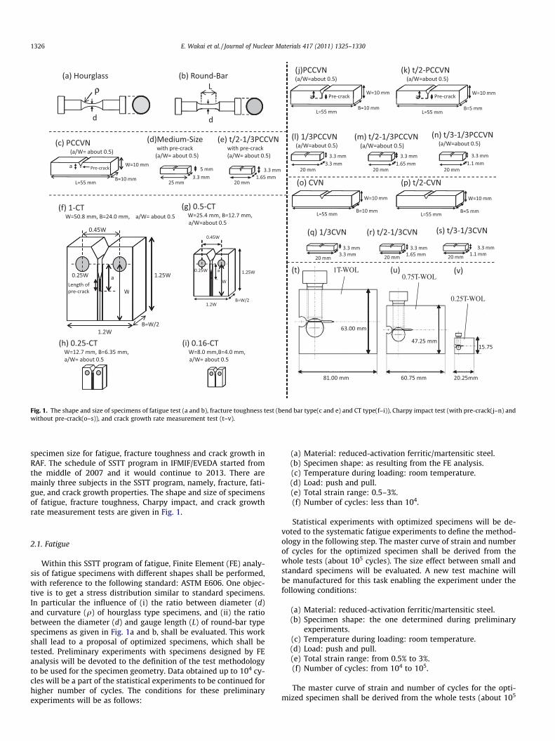
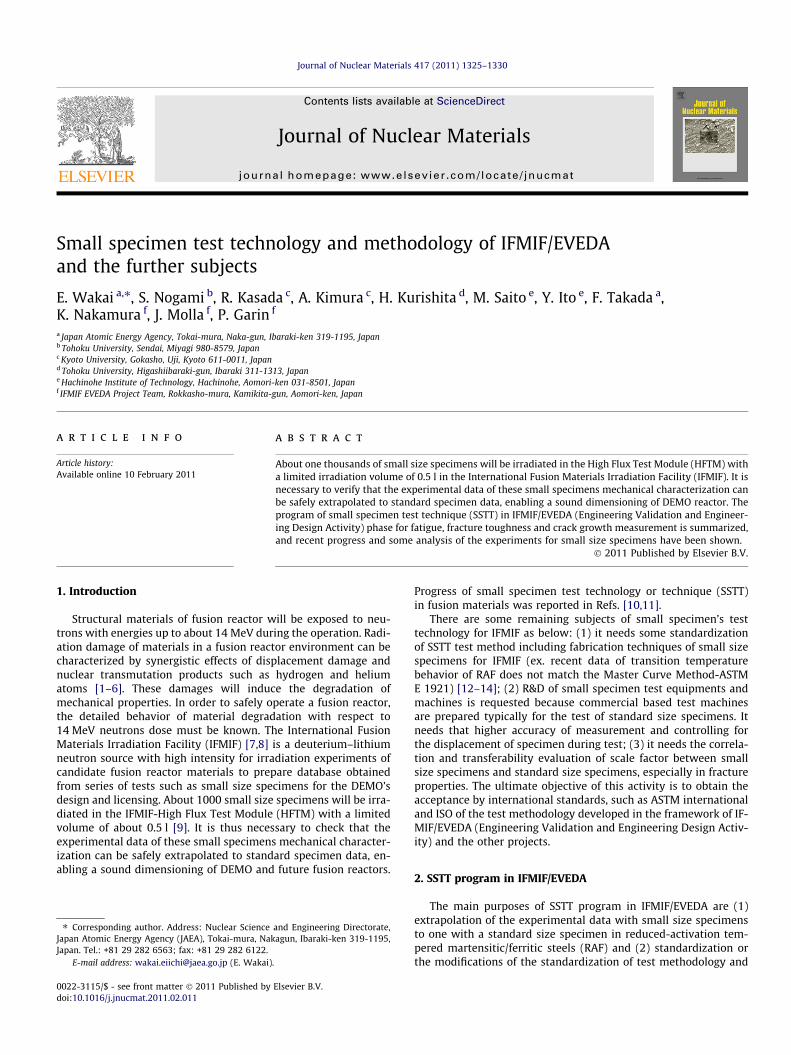
Fig. 1. The shape and size of specimens of fatigue test (a and b), fracture toughness test (bend bar type(c and e) and CT type(f–i)), Charpy impact test (with pre-crack(j–n) andwithout pre-crack(o–s)), and crack growth rate measurement test (t–v).
1326 E. Wakai et al. / Journal of Nuclear Materials 417 (2011) 1325–1330
specimen size for fatigue, fracture toughness and crack growth inRAF. The schedule of SSTT program in IFMIF/EVEDA started fromthe middle of 2007 and it would continue to 2013. There aremainly three subjects in the SSTT program, namely, fracture, fati-gue, and crack growth properties. The shape and size of specimensof fatigue, fracture toughness, Charpy impact, and crack growthrate measurement tests are given in Fig. 1.
2.1. Fatigue
Within this SSTT program of fatigue, Finite Element (FE) analy-sis of fatigue specimens with different shapes shall be performed,with reference to the following standard: ASTM E606. One objec-tive is to get a stress distribution similar to standard specimens.In particular the influence of (i) the ratio between diameter (d)and curvature (q) of hourglass type specimens, and (ii) the ratiobetween the diameter (d) and gauge length (L) of round-bar typespecimens as given in Fig. 1a and b, shall be evaluated. This workshall lead to a proposal of optimized specimens, which shall betested. Preliminary experiments with specimens designed by FEanalysis will be devoted to the definition of the test methodologyto be used for the specimen geometry. Data obtained up to 104 cy-cles will be a part of the statistical experiments to be continued forhigher number of cycles. The conditions for these preliminaryexperiments will be as follows:
(a) Material: reduced-activation ferritic/martensitic steel.(b) Specimen shape: as resulting from the FE analysis.(c) Temperature during loading: room temperature.(d) Load: push and pull.(e) Total strain range: 0.5–3%.(f) Number of cycles: less than 104.
Statistical experiments with optimized specimens will be de-voted to the systematic fatigue experiments to define the method-ology in the following step. The master curve of strain and numberof cycles for the optimized specimen shall be derived from thewhole tests (about 105 cycles). The size effect between small andstandard specimens will be evaluated. A new test machine willbe manufactured for this task enabling the experiment under thefollowing conditions:
(a) Material: reduced-activation ferritic/martensitic steel.(b) Specimen shape: the one determined during preliminary
experiments.(c) Temperature during loading: room temperature.(d) Load: push and pull.(e) Total strain range: from 0.5% to 3%.(f) Number of cycles: from 104 to 105.
The master curve of strain and number of cycles for the opti-mized specimen shall be derived from the whole tests (about 105
E. Wakai et al. / Journal of Nuclear Materials 417 (2011) 1325–1330 1327
cycles) performed. The test method for small specimens will beproposed based on the experimental results. The transferabilityof the test technology to hot cell laboratories shall be analyzed inthis phase including the specific potential issues such as remotehandling, and radiation strength of sensors/electronics.
The results of some experiments in recent progress [15] areshown in Fig. 2. The miniature hourglass specimen showed longerfatigue life at high strain ranges and shorter fatigue life at lowstrain ranges than that of the standard-size round-bar specimen.The miniature round-bar specimen showed almost the same fati-gue life as that of the standard-size round-bar specimen.
2.2. Fracture toughness
In the fundamental evaluation and tests of fracture toughness,similarly to the fatigue samples, finite element calculations shallbe conducted to evaluate the effect of the size on the samplesstresses and help optimizing their dimensioning. The first experi-
(a)
(b)
Fig. 2. The relations between total strain range and number of cycle to fatigue [13]:(a) in three types of small size specimens with different shapes and standard sizewith round-bar shape, (b) small size specimens and standard size specimens inpresent result and previous ones.
mental examination shall aim to optimize the methodology that,based on ASTM E813-89, should be used with these specimensand to evaluate the effect of size in the results. This first experi-mental examination shall be performed according to the followingcharacteristics:
(a) Specimens’ material: reduced-activation ferritic/martensiticsteel.
(b) Specimens’ type: three point bending type with three differ-ent sizes and compact tension (CT) type with four differentsizes (Fig. 1c–e and f–i).
(c) Experimental temperature: room temperature.(d) Experimental method: based on ASTM E813-89.(e) Pre-crack condition will be checked by means of tensile test
experiments.
The objective of this phase is the systematic measurement offracture toughness with optimized specimens and following themethodology defined in next step. This experimental examinationwill be performed according to the following technical specifica-tions of static and dynamic tests.
2.2.1. Static testsThe static tests of fracture toughness will be performed as
below:
(i) Experimental method: the one defined in this study basedon ASTM E813-89, E1820-99a, E1921-02.
(ii) Specimens’ material: reduced-activation ferritic/martensiticsteel.
(iii) Specimens’ shape: three point bending type and CT type.(iv) Specimen size: three different sizes (Fig. 1c–e) for three
point bending type and four different sizes for CT type(Fig. 1f–i).
(v) Experimental temperature: five temperature points every40–50 �C from about �190 �C to room temperature.
The specimen size effect on J-integral, K (toughness) and transi-tion temperature or To, reference temperature between small andstandard specimens using master curve analysis shall be evaluated.The fracture shall be mainly analyzed by means of Optical Micros-copy and Scanning Electron Microscopy (SEM).
2.2.2. Dynamic tests (Charpy impact tests)The dynamic tests of fracture toughness will be performed as
below:
(i) Experimental method: Charpy impact.(ii) Specimens’ shape: three point bending type with pre-crack-
ing (see Fig. 1j–n) and without pre-cracking (see Fig. 1o–s).(iii) Specimen size: two types of standard size specimens and
three types of small size specimens.(iv) Experimental temperature: temperatures ranging from
�190 �C to room temperature.
The DBTT shall be also evaluated for Charpy impact tests. Thefracture shall be mainly analyzed by means of Optical Microscopyand Scanning Electron Microscopy (SEM).
Table 1Dependence of specimen size on DBTT of F82H steel in Charpy impact tests.
Specimen type B (mm) b (mm) L (mm) DBTT (�C)
t/2-CVN 5 8 55 �821/3CVN 3.3 2.79 20 �104t/2-1/3CVN 1.65 2.79 20 �140
(a)
(b)
(c)
9 mm
1.65 mm
20 mm
3.30 mm
1.65 mm
0.8 mm 1.4 mm
Block
Slice & Size adjustment due to
20 mm or
15.6 mm 21.7 mm
3.3 mm
3.3m
21.7 mm
20 mm or
15.6 mm
0.5mm
V-notch , U-notch width 0.2mm)
Pre-crack due to fatigue
1.65 mm
)
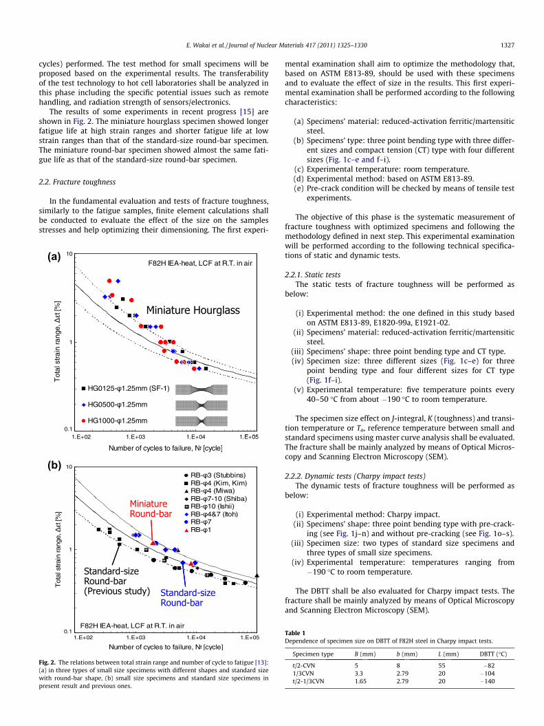
Fig. 3. (a) An example of specimen preparation of DFMB and t/2-1/3PCCVNspecimens in case by using plate, small bend specimens of (b) t/2 of 1/3PCCVN with20 mm length and (c) DFMB with 9 mm length.
1328 E. Wakai et al. / Journal of Nuclear Materials 417 (2011) 1325–1330
This activity is finally devoted to the analysis of experimentalresults and to the proposal of methodology of fracture toughnessmeasurement with small specimens. It shall also include the anal-ysis of the consequences of handling irradiated samples on thisexperimental characterization. The transferability of the test tech-nology to hot cell laboratories will be analyzed in this phase
Table 2Conditions of pre-crack induced cyclic fatigue prepared from the plate of F82H steel.
Specimen type Max. load (N) Min. load (N) Fr
t/2-1/3PCCVN (20 mm-L) with V-notch 1079 108 40981 98 40883 88 40
DFMB (9 mm-L, 1.65 mm-square) with U-notch 2942 294 35DFMB (9 mm-L, 1.65 mm-square) with U-notch 1079 108 35
Table 3Conditions of cyclic fatigue inducing a pre-crack in a piece of small size specimen t/2-1/3
Specimen ID Max. load (N) Min. load (N) Frequency (Hz) Crack length a1
CA200-3 461 46 30 0.2363 36 30 0.5294 29 30 0.7226 23 30 1.0177 18 30 1.3
CA200-5 422 42 30 0.3333 33 30 0.4265 27 30 0.7206 21 30 1.0157 16 30 1.3
CA200-7 373 37 30 0.2294 29 30 0.4226 23 30 0.7177 18 30 1.0137 14 30 1.3
CA200-9 297 30 30 0.2238 24 30 0.4191 19 30 0.7152 15 30 1.0122 12 30 1.3
including the specific potential issues such as remote handling,and radiation strength of sensors/electronics. The behavior ofwelded and brittle RAF/M steel samples shall be also studied with-in this activity.
The previous results [16] of Charpy impact tests of F82H steelfor some different size specimens are given in Table 1. In presentanalysis, we have evaluated the relation of DBTT between smallsize specimen and standard size specimen. In empirical correla-tions of DBTT of full size and sub-size specimens in RPV steels(A533B steel), it was proposed by Sokolov [17]:
DBTTðfullÞ ¼ DBTTðsubÞ þ 98� 15:1� lnðBb2Þ ðin Ref : ½17�Þ: ð1Þ
In the correlation of DBTT between small size specimen and stan-dard size specimen for F82H steel, it has to be modified as below
DBTTðfullÞ ¼ DBTTðsubÞ þ 25� 15:1
� lnðBb2Þ ðin present studyÞ: ð2Þ
The difference between Eqs. (1) and (2) is a very important result.To understand this difference we will need some physical model,and DBTT-size correlation may be some functions of mechanicalproperties such as yield stress, fracture stress, elongations, andthe densities of obstacles such as inclusions and precipitations.
In this framework, the conditions of pre-crack induced by cyclicfatigue in the plate of F82H steel were checked. The procedure ofpreparation of DFMB and t/2-1/3PCCVN specimens is shown inFig. 3. The block’s cutting, V-notch or U-notch cutting, pre-crackdue to fatigue, and slice & size adjustment by mechanical polishingare continuously performed. The conditions of pre-crack due to fa-tigue of three point bending were performed in the span of threepoint bending with width of 12 mm. The fatigue pre-cracks of t/2-1/3PCCVN and DFMB specimens were induced by using a fatiguetesting machine, Shimazu Lab-5u. In the t/2-1/3PCCVN and DFMB
equency (Hz) Pre-crackposition (mm)
Total length ofpre-crack (mm)
No. of cycles Total no.of cycles
0–0.2 0.2 0–100,000 100,0000.2–0.5 0.5 100,000–130,000 130,0000.5–1.3 1.3 130,000–180,000 180,0000–0.6 0.6 0–200,000 200,0000.0–0.0 0.0 0–400,000 400,000
PCCVN of F82H steel.
(mm) Crack length a2 (mm) Number of cycles Final K (max) (MPap
m)
0.2 54,000 200.4 95,000 180.6 128,000 190.9 196,000 181.3 254,000 19
0.2 90,000 180.4 139,000 170.8 234,000 171.0 305,000 171.3 404,000 17
0.2 165,000 160.5 257,000 150.8 416,000 141.1 552,000 141.3 658,000 15
0.2 404,000 130.4 490,000 120.7 711,000 121.0 920,000 121.3 1064,000 13
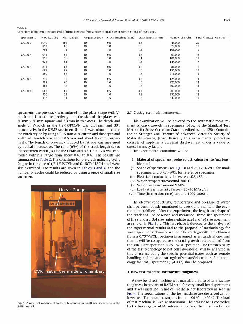
Table 4Conditions of pre-crack induced cyclic fatigue prepared from a piece of small size specimen 0.16CT of F82H steel.
Specimen ID Max. load (N) Min. load (N) Frequency (Hz) Crack length a1 (mm) Crack length a2 (mm) Number of cycles Final K (max) (MPap
m)
CA200-2 1040 104 30 0.5 0.5 45,000 20853 85 30 1.0 1.0 72,000 19706 71 30 1.5 1.6 105,000 19
CA200-4 941 94 30 0.5 0.6 63,000 18755 76 30 1.0 1.1 106,000 17628 63 30 1.5 1.5 144,000 17
CA200-6 834 83 30 0.6 0.4 86,000 16667 67 30 1.0 1.0 155,000 15559 56 30 1.5 1.5 216,000 15
CA200-8 745 75 30 0.5 0.4 125,000 14598 60 30 1.0 1.0 227,000 14481 48 30 1.5 1.5 307,000 13
CA200-10 667 67 30 0.5 0.4 203,000 13530 53 30 1.0 0.9 337,000 12412 41 30 1.5 1.4 547,000 11
E. Wakai et al. / Journal of Nuclear Materials 417 (2011) 1325–1330 1329
specimens, the pre-crack was induced in the plate shape with V-notch and U-notch, respectively, and the size of the plates was20 mm � 20 mm square and 3.3 mm in thickness. The depth andangle of V-notch in the t/2-1/3PCCVN was 0.51 mm and 30�,respectively. In the DFMB specimen, U-notch was adopt to reducethe notch region by using a 0.15 mm wire cutter, and the depth andwidth of U-notch was about 0.5 mm and about 0.2 mm, respec-tively. The length of pre-crack induced by fatigue was measuredby optical microscope. The ratio (a/W) of the crack length (a) tothe specimen width (W) for the DFMB and t/2-1/3PCCVN was con-trolled within a range from about 0.40 to 0.45. The results aresummaried in Table 2. The conditions for pre-crack inducing cyclicfatigue in the case of t/2-1/3PCCVN and 0.16CTof F82H steel werealso examined. The results are given in Tables 3 and 4, and thenumber of cycles could be reduced by using a piece of small sizespecimen.
Fig. 4. A new test machine of fracture toughness for small size specimens in theJMTR hot cell.
2.3. Crack growth rate measurement
This examination will be devoted to the systematic measure-ment of crack growth in specimens following the Standard TestMethod for Stress Corrosion Cracking edited by the 129th Commit-tee on Strength and Fracture of Advanced Materials, Society ofMaterials Science, Japan. Basically this experimental procedureconsists of applying a constant displacement under a value ofstress intensity factor.
The experimental conditions will be:
(i) Material of specimens: reduced-activation ferritic/martens-itic steel.
(ii) Shape of specimens (see Fig. 1u and v: 0.25T-WOL for smallspecimen and 0.75T-WOL for reference specimen.
(iii) Electrical conductivity for water: <0.3 lS/cm.(iv) Water temperature:around 300 �C.(v) Water pressure: around 9 MPa.
(vi) Load (stress intensity factor): 20–40 MPap
m.(vii) Time (immersion time): around 1000–2000 h.
The electric conductivity, temperature and pressure of watershall be continuously monitored to check and maintain the envi-ronment stabilized. After the experiment, the length and shape ofthe crack shall be observed and measured. Three size specimensof the standard, 3/4 size (intermediate size) and 1/4 size specimensare shown in Fig. 1t–v. This last phase is devoted to the analysis ofthe experimental results and to the proposal of methodology forsmall specimens’ characterization. The crack growth rate obtainedfrom a 0.75T-WOL specimen is assumed as a standard one, andthen it will be compared to the crack growth rate obtained fromthe small size specimen, 0.25T-WOL specimen. The transferabilityof the test technology to hot cell laboratories will be analyzed inthis phase including the specific potential issues such as remotehandling, and radiation strength of sensors/electronics. A method-ology for small specimens (1/4 size) shall be proposed.
3. New test machine for fracture toughness
A new bend test machine was manufactured to obtain fracturetoughness behaviors of RAFM steel for very small bend specimensand it was installed in hot cell of JMTR hot laboratory as seen inFig. 4. The specifications of the test machine are described as fol-lows: test Temperature range is from �190 �C to 400 �C. The loadof test machine is 5 kN at maximum. The crosshead is controlledby the linear gauge of Mitsutoyo, LGF series. The cross head speed
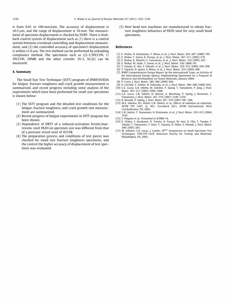
1330 E. Wakai et al. / Journal of Nuclear Materials 417 (2011) 1325–1330
is from 0.01 to 100 mm/min. The accuracy of displacement is±0.5 lm, and the range of displacement is 10 mm. The measure-ment of specimen displacement is checked by DVRT. There is feed-back control system of displacement such as (1) there is a controlsystem between crosshead controlling and displacement measure-ment, and (2) the controlled accuracy of specimen’s displacementis within ±1.0 lm. The test method can be performed by unloadingcompliance method. The specimens such as t/2-1/3PCCVN, 1/3PCCVN, DFMB and the other (tensile: SS-3, SS-J3) can bemeasured.
4. Summary
The Small Size Test Technique (SSTT) program of IFMIF/EVEDAfor fatigue, fracture toughness and crack growth measurement issummarized, and recent progress including some analysis of theexperiments which have been performed for small size specimensis shown below:
(1) The SSTT program and the detailed test conditions for thefatigue, fracture toughness, and crack growth rate measure-ment are summarized.
(2) Recent progress of fatigue experiments in SSTT program hasbeen shown.
(3) Dependence of DBTT of a reduced-activation ferritic/mar-tensitic steel F82H on specimen size was different from thatof a pressure vessel steel of A533B.
(4) The preparation process and conditions of test pieces waschecked for small size fracture toughness specimens, andthe control the higher accuracy of displacement of test spec-imen was evaluated.
(5) New bend test machines are manufactured to obtain frac-ture toughness behaviors of F82H steel for very small bendspecimens.
References
[1] E. Wakai, N. Hashimoto, Y. Miwa, et al., J. Nucl. Mater. 283–287 (2000) 799.[2] E. Wakai, T. Sawai, K. Furuya, et al., J. Nucl. Mater. 307–311 (2002) 278.[3] E. Wakai, K. Kikuchi, S. Yamamoto, et al., J. Nucl. Mater. 318 (2003) 267.[4] E. Wakai, M. Ando, T. Sawai, et al., J. Nucl. Mater. 356 (2006) 95.[5] T. Tanaka, K. Oka, S. Ohnuki, et al., J. Nucl. Mater. 329–333 (2004) 294–298.[6] T. Taguchi, N. Igawa, S. Miwa, et al., J. Nucl. Mater. 335 (2004) 508.[7] IFMIF Comprehensive Design Report, by the International Team, an Activity of
the International Energy Agency, Implementing Agreement for a Program ofResearch and Development on Fusion Materials, January 2004.
[8] P. Garin, J. Nucl. Mater. 386–388 (2009) 944.[9] D. Leichtle, F. Arbiter, B. Dolensky, et al., J. Nucl. Mater. 386–388 (2009) 954.
[10] G.E. Lucas, G.R. Odette, M. Sokolov, P. Spatig, T. Yamamoto, P. Jung, J. Nucl.Mater. 307–311 (2002) 1600–1608.
[11] G.E. Lucas, G.R. Odette, H. Matsui, A. Moselang, P. Spatig, J. Rensman, T.Yamamoto, J. Nucl. Mater. 367–370 (2007) 1549–1556.
[12] R. Bonadé, P. Spätig, J. Nucl. Mater 367–370 (2007) 581–586.[13] M.A. Sokolov, R.L. Klueh, G.R. Odette, et al., Effects of radiation on materials,
ASTM STP 1447, in: M.L. Grossbeck (Ed.), ASTM International, WestConshohocken, PA, 2003.
[14] G.R. Odette, T. Yamamoto, H. Kishimoto, et al., J. Nucl. Mater. 329–333 (2004)1243.
[15] S. Nogami et al., Presented in ICFRM-14.[16] E. Wakai, S. Jitsukawa, H. Tomita, K. Furuya, M. Sato, K. Oka, T. Tanaka, F.
Takada, T. Yamamoto, Y. Kato, Y. Tayama, K. Shiba, S. Ohnuki, J. Nucl. Mater.348 (2005) 285.
[17] M. Sokolov, G.E. Lucas, J. Landes, 4PthP Symposium on Small Specimen TestTechniques, STM-STP-1418, American Society for Testing and Materials,Philadelphia, PA, 2003.


![Present Status of the Accelerator System in the IFMIF ... · PDF filePresent Status of the Accelerator System in the IFMIF/EVEDA ... devices along the beam line were chosen [11]. Fig](https://img.pdfslide.us/doc/110x75/5a9e45967f8b9aee4a8c2ba2/present-status-of-the-accelerator-system-in-the-ifmif-status-of-the-accelerator.jpg)