Embed Size (px)
Citation preview

2007 AFRC - JFRC International Symposium October 16-18, 2006, Marriott Waikoloa, Hawaii
- Advances in Combustion Technology:
Improving the Environment and Energy Efficiency
Small Capacity Regenerative Burners
Author: Joachim G. Wuenning, WS Inc., Elyria, Ohio
Abstract
Regenerative combustion air preheating became increasingly popular due to rising energy
costs. Advances in the abatement of NOx-formation made it possible to lower emissions in
new installation despite high air preheating temperatures. Now, there are many regenerative
fired furnaces in the steel industry, many of them in the large reheating furnaces.
But there is still are large potential in energy savings. Besides the large firing capacities in
reheating furnaces, there are many heat treating furnaces with smaller capacity burners and
also radiant tube heated furnaces. Small capacity regenerative burner systems require different
concepts which will be discussed in the presentation.

Energy Efficiency related to flue gas losses
Efficiency is usually defined as:
efficiency = benefit
expenditure
Regarding firing systems for industrial furnaces, efficiency or available heat is defined as:
efficiency = fuel input - exhaust gas losses
fuel input = 1 - fuel input - exhaust gas losses
fuel input
Figure 1 shows the efficiency as a function of exhaust gas, or process temperature. For a
system without air preheat, it becomes obvious that the efficiency is vanishing with rising
exhaust gas temperature. At a 1000°C process temperature, at least 50% of the fuel input will
be lost as hot exhaust gas heat.
Figure 1: Efficiency
To determine the usefullness of air preheat, the relative air preheat ε can be defined as:
ε = ϑpreheat - ϑair
ϑexhaust - ϑair º
ϑpreheat
ϑexhaust

with:
ϑpreheat air preheat temperature [°C]
ϑexhaust hot exhaust temperature [°C]
ϑair air inlet temperature [°C]
The air preheat temperature is the temperature which is supplied to the burner. Energy losses
between a central heat exchanger and the burner have to be considered. The hot exhaust
temperature is the temperature of the exhaust gases leaving the furnace. In most cases this
temperature is close to the process temperature. In radiant tube heated furnaces this
temperature can be substantially higher than the furnace temperature. The air inlet
temperature is usually ambiant air and therefore the relative air preheat can be expressed as
the ratio of preheat temperature to hot exhaust temperature. The relative air preheat is a good
figure to characterize a heat exchanger for air preheating.
Figure 2: Heat exchanber performance
A heat exchanger performance is evaluated by the NTU – number of transfer unit. The NTU
are proportional to the heat exchanger area and inversely proportional to the heat capacity
flow through the heat exchanger.
NTU = kΩAmΩcp

with: A - heat exchanger surface area
k – heat transfer coefficient
m – mass flow
cp – specific heat
Figure 2 shows the relative air preheat in a simplified diagramm for counterflow and coflow
heat exchangers.
What can be seen in the diagramm is, that it is relatively easy to achieve a relative air preheat
of 0.4 to 0.5 with counterflow or coflow heat exchangers. But to gain more air preheat,
requires effective counterflow heat exchangers with large heat exchanger surface areas. To get
to high air preheat temperatures (relative air preheat of 0.8 to 0.9), requires 5 to 10 times
higher heat exchanger surface areas compared to a relative air preheat of 0.5.
The savings can be calculated as:
savings =1 - low efficiencyhigh efficiency
That translates to savings of 20% if a system with 68% efficiency is upgraded to 85%
efficiency.
Energy efficiency is not a new topic1, but it has gained popularity lately due to rising energy
prices.
Continous direct fired furnaces
Figure 3: Direct fired contninous furnace
One option, shown in Figure 3, to lower the exhaust gas losses is to add an unheated section
to the furnace where the incoming products are preheated. This is quite effective as long as
the flue gas is hot but to really transfer considerable amounts of heat, very long preheat zones

would be necessary. This method to improve efficiency is common in the ceramic industry in
tunnel furnaces.
Figure 4: Continous furnace with central recuperator
Additional usefull cooling of exhaust gases can be done in a central heat exchanger (Figure
4). The limitation here is coming from the design and size of the recuperator as well as the
maximum temperature for the hot air control valves. Common air preheat temperatures are
300° to 500° and in some cases as high as 600°C.
Figure 5: Decentralized heat recovery
The limitations for air preheating could be overcome with self recuperative burners (Figure 6)
or regenerative burner systems for decentralized heat recovery (Figure 5). Here every burner

has its own heat exchanger which is placed in the furnace wall or close to the burner. The
combustion air control valves are located on the cold side of the heat exchangers. Besides
higher efficiency, such a system provides a more excact furnace temperature control because
there is no interaction between the furnace zones. The lack of the costly insulated hot air
piping and a preheat zone usually offsets the higher burner costs and the expenditure for the
exhaust collection system. Energy savings of 10 to 30% compared to systems with central
recuperators can be achieved.
Figure 6: Self recuperative burner REKUMAT® (WS GmbH)
Even higher airpreheat temperatures and therefore higher efficiency can be achieved with
regenerative burners. For larger burner capacites, regenerative burner pairs are common. As
shown in Figure 7, two burners are linked and are firing alternately. Exhaust and combustion
air are directed over the regenerators which are made of ceramic balls or honeycombs.
Relative air preheat of 0.8 to 0.9 are achievable, making these systems very effective. Figure 8
shows one of the regenerative burners. The burner uses air staging as NOx-reducing measure 2.

Figure 7: Regenerative burner pair Figure 8: Regenerative burner (Bloom)
For smaller capacities, a self regenerative burner allows the same high efficiency, but with the
advantage of a single burner solution 3. There is no need to switch from one burner to another
and the one burner can fire continously, just like a recuperative burner. This is possible by
integrating all switching valves and regenerators into one compact unit, as shown in Figure 9
and Figure 10.
Figure 9: Self regenerative burner Figure 10: REGEMAT® (WS GmbH)
Fuel saving compared to self recuperators are in the range of 10 to 20% and savings of 50%
and more compared to cold air systems were achieved. Low NOx combustion is achieved by
flameless oxidation 4, FLOX® (registered trademark of WS Wärmeprozesstechnik, Renningen, Germany).
Radiant tube fired systems
For radiant tubes, decentralized heat recovery is preferable. Central heat exchangers, which
are common for large direct fired furnaces are not practical for radiant tube fired systems
because there is no central exhaust outlet of the furnace. The hot exhaust gases would have to
be transported to the heat exchanger in costly insulated ducts and then the hot air has to be
distributed back to the individual radiant tubes. For radiant tube heating, a good heat recovery
system is essential since the exhaust temperatures are often substantially higher than the
furnace temperature. That is particularly true for ceramic radiant tubes with high heat release
rates.
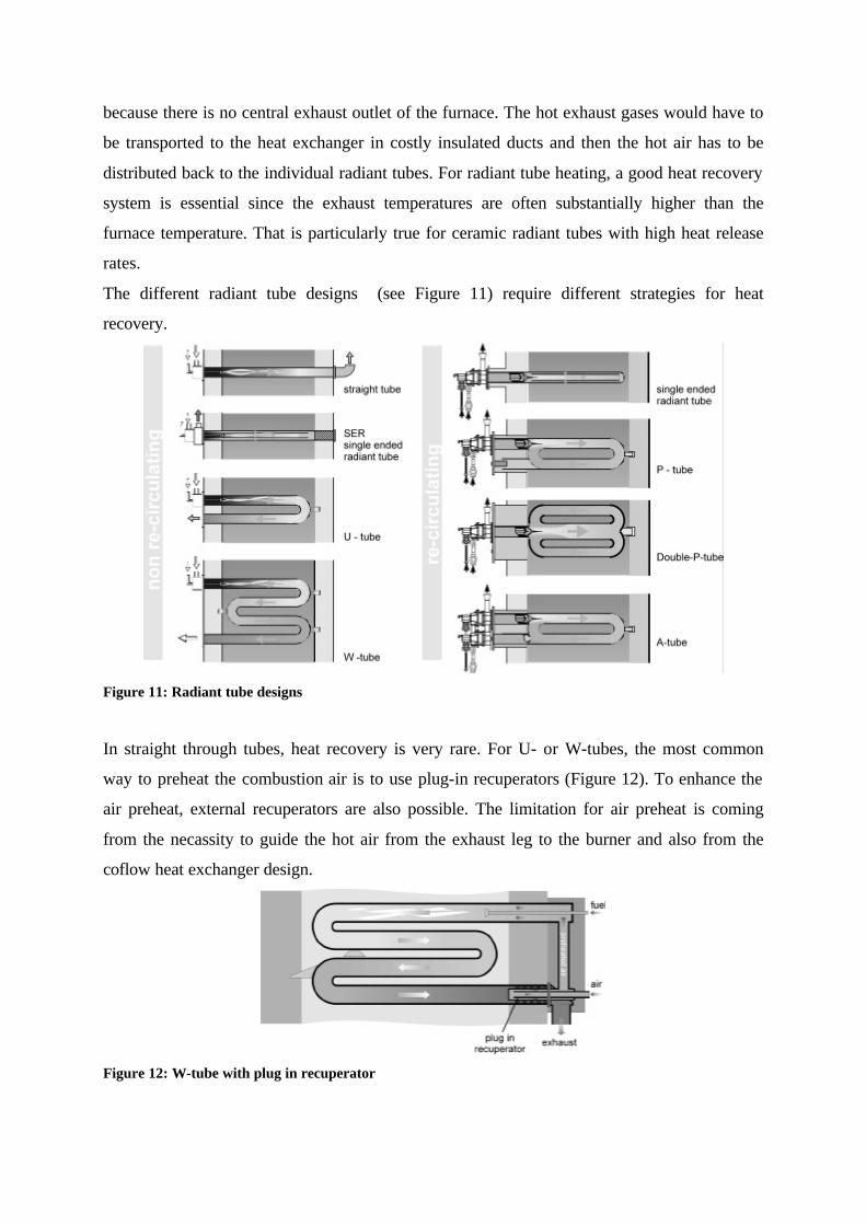
The different radiant tube designs (see Figure 11) require different strategies for heat
recovery.
Figure 11: Radiant tube designs
In straight through tubes, heat recovery is very rare. For U- or W-tubes, the most common
way to preheat the combustion air is to use plug-in recuperators (Figure 12). To enhance the
air preheat, external recuperators are also possible. The limitation for air preheat is coming
from the necassity to guide the hot air from the exhaust leg to the burner and also from the
coflow heat exchanger design.
Figure 12: W-tube with plug in recuperator

Higher air preheat temperatures and thereby higher effiency can be achieved with
regenerative burner systems in U-, W- and A-tubes. Two burners per tube are firing
alternating (see Figure 13). The regenerative systems allow air preheat temperatures close to
the furnace temperature. Energy savings of more than 20% compared to systems with plug in
recuperators are typical. Besides energy savings, the temperature uniformity of the tubes are
much better due to the alternating flow direction in the tube. Attention has to be paid to NOx-
formation due to the high air preheat and also the complexity of the system due to two burners
per tube.
Figure 13: regenerative fired W-tube
Single ended, P- and Double-P tubes are usually fired with self recuperative burners. The
counterflow heat exchanger, which is placed inside the furnace wall, allows high air preheat
temperatures and there is no hot air piping required outside the furnace. For high
temperatures, self recuperative burners with ceramic heat exchangers (see Figure 6) are
available. Air preheat temperatures in the range of 500 to 700°C are typical. Figure 14 shows
a double-P tube with a self recuperative burner. High velocity combustion results in a good
temperature uniformity and internal recirculation allows the application of flameless oxidation
FLOX®, as an effective method to reduce thermal NOx formation. Self recuperative burners a
widely used since they combine good performance with a high efficiency.

Figure 14: Double-P-tube with self recuperative burner
Figure 15: Double-P-tube with self recuperative burner
Figure 16: Double-P-tube with self regenerative burner
To combine the advantages of regenerative systems and self recuperative burners, a self
regenerative burner for radiant tubes was developped.

Figure 17: Self regenerative radiant tube burner, REGEMAT® 250 (WS GmbH)
Figure 17 shows a self regenerative burner which could be used for direct firing and for
heating of recirculating radiant tubes. The self regenerative burner is used in combination
with a pulse firing system, that means, the burner is on/off controlled. All the logic for
regenerative switching, flame safety, ignition and valve operation is handled by a local burner
control unit. That makes the installation, start up and maintenance as easy as with self
recuperative burners. The tube temperature uniformity is excellent because of the internal
recirculation and NOx emissions are low due to flameless oxidation.
To keep the number of radiant tubes and burners, and therebye the costs, at a minimum,
radiant tubes with a large tube diameter should be used. With double-P tubes, it is possible to
heat a furnace with fraction of burners compared to a system with small diameter straight
tubes.

Conclusions
There are many options for increasing the energy efficiency. Preheating the combustion air is
the most effective way to increase efficiency in most furnaces. To fight the challenges of
rising energy cost and environmental regulations, a close cooperation of the end user, the
furnace builder and the burner manufacturer is necessary to choose the best possible
configuration with respect to:
- performance
- energy efficiency
- low emissions
- low maintenance
and of course not higher than needed investment costs.
1 Combustion Engineering and Gas Utilization, J.R. Cornforth, 3rd edition 1992, British Gas, London 2 Dave Schalles, Greenhouse Gas Reduction Options Applied to Metals Industry, 2002 AFRC Meeting, Houston 3 Milani A., Salomone GV., Wünning J., Advanced Regenerative Design Cuts Air Pollution, Advanced Steel 1998-99, UK 4 Wünning J., Flameless Oxidation: Combustion with low NOx-emissions even at high air preheat temperatures 2002 AFRC Meeting, Houston


![Spinal cord-specific deletion of the glutamate transporter ... · Consistent with previous report [19], the strong tdTomato ... Hoxb8-Cre/GLT1 flox/flox mice had slightly lower body](https://img.pdfslide.us/doc/110x75/5b0a0b357f8b9ae61b8b7d58/spinal-cord-specific-deletion-of-the-glutamate-transporter-with-previous-report.jpg)