Embed Size (px)
Citation preview
Mat
–N
r. 66
9888
/ 30
.07.
2012
D
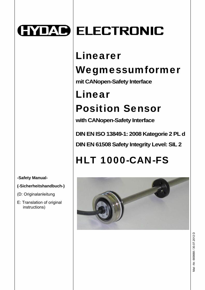
-Safety Manual-
(-Sicherheitshandbuch-)
(D: Originalanleitung
E: Translation of original instructions)
Linearer Wegmessumformer mit CANopen-Safety Interface
Linear Position Sensor with CANopen-Safety Interface
DIN EN ISO 13849-1: 2008 Kategorie 2 PL d
DIN EN 61508 Safety Integrity Level: SIL 2
HLT 1000-CAN-FS

Mat
–N
r. 66
9888
/ 30
.07.
2012
D
2
Mat
–N
r. 66
9879
/ 30
.07.
2012
D
3
Inhalt
1 Allgemeine Angaben 4 1.1 Autor, Version, Datum, Dokumentname, Dateiname 4 1.2 Versionshistorie und Änderungsvermerke 4
2 Geltungsbereich 4
3 Produktbeschreibung 5
4 Funktionale Sicherheit 5 4.1 Relevante Normen 5 4.2 Konformität 5 4.3 Beschreibung der Sicherheitsfunktionen 5 4.3.1 Ungestörter Betrieb 6 4.3.2 Sicherer Zustand 6 4.3.3 Gefährlicher Fehler 6
5 Spezifikation (Auszug) 6 5.1 Diagnosezeiten 6 5.2 Elektrischer Anschluss 6 5.3 Umwelt 7 5.3.1 Temperaturbereich 7 5.3.2 Mechanisches Umfeld 7 5.4 Eingangskenngrößen 7 5.5 Ausgangskenngrößen 7
6 Bedienelemente 7
7 Inbetriebnahme 7
8 Intervall für Wiederholungsprüfungen 8
9 Sicherheitstechnische Kennzahlen 8 9.1 Performance Level 8 9.2 Safety Integrity Level 8
10 Glossar 9 10.1 Begriffe aus der DIN EN ISO 13849 9 10.2 Begriffe aus der DIN EN 61508 9
11 CE-Konformitätserklärung 10
12 TÜV-Zertifikat 11
Mat
–N
r. 66
9888
/ 30
.07.
2012
D
4
1 Allgemeine Angaben
1.1 Autor, Version, Datum, Dokumentname, Dateiname Autor: W. Bregel (BREW) Version: 1.1 Datum: 30.07.2012 Dokumentname: Safety Manual Dateiname: SM_HLT_1000_CAN_FS_D_669888_2012-07-30.pdf
1.2 Versionshistorie und Änderungsvermerke Version Datum Autor ÄnderungV1.0 05.06.2012 BREW Erste Ausgabe – Entwurf ohne Zertifikats Nummer V1.1 30.07.2012 BREW FS-Kennwerte + Zertifikat
2 Geltungsbereich Dieses Sicherheitshandbuch gilt für folgende Wegmessumformer der Serie HLT 1000–CAN-FS für funktionale Sicherheit:
HLT 1100-R2-xxx-CAN-xxxx-S2PD-000 | | | | | | | | | | | | | +-- Modifikation | | | | | | 000 = Standard | | | | | +------- SIL2/PL=d | | | | +------------ Messlänge | | | | | in mm | | | +---------------- Schnittstelle | | | CAN = CANopen Safety | | +-------------------- Anschluss | | Kxx = freies Kabel | | (xx = Länge in m) | | Lxx = M12x1 Flanschstecker | | an Einzeladern | | (xx = Länge in cm) | +----------------------- Anschlussart | R2 = Zylinderintegriert +---------------------------- Bauart 1 = Stab
Mat
–N
r. 66
9888
/ 30
.07.
2012
D
5
3 Produktbeschreibung Die Wegmessumformerserie HLT 1000-CAN-FS wurde speziell für den Serieneinsatz in Hydraulikzylindern, z. B. in Mobilanwendungen, entwickelt und dient der sicheren Detektion der Kolbenstangenposition von Hydraulikzylindern. Der HLT 1000-CAN-FS basiert auf dem robusten, langlebigen und kontaktfreien Prinzip der Magnetostriktion. Die Gehäuseform und die Geometrie sind so beschaffen, dass ein Falscheinbau in den Zylinder nicht möglich ist. Zur Einbindung in moderne Steuerungen steht eine CANopen-Safety Schnittstelle zur Verfügung. Der Wegmessumformer HLT 1000-CAN-FS ist für den Einsatz in Sicherheitskreisen / Sicherheitsfunktionen im Rahmen der funktionalen Sicherheit von Maschinen bis SIL2 (DIN EN 61508) bzw. PL='d' Kat 2 (DIN EN ISO 13849-1:2008) bestimmt. Der Wegmessumformer dient als Sensorelement (SRP/CS) einer elektronischen Steuerung (E/E/PE-System).
4 Funktionale Sicherheit
4.1 Relevante Normen Performance Level
DIN EN ISO 13849-1: 2008-1 Sicherheit von Maschinen – Sicherheitsbezogene Teile von Steuerungen – Teil1: Allgemeine Gestaltungsleitsätze
Safety Integrity Level DIN EN 61508: 2001 Funktionale Sicherheit sicherheitsbezogener elektrischer/elektronischer/programmierbarer elektronischer Systeme
CANopen (CAN in Automation - CiA)
DS 301, DS 302, DS 304, DS 305, DS406
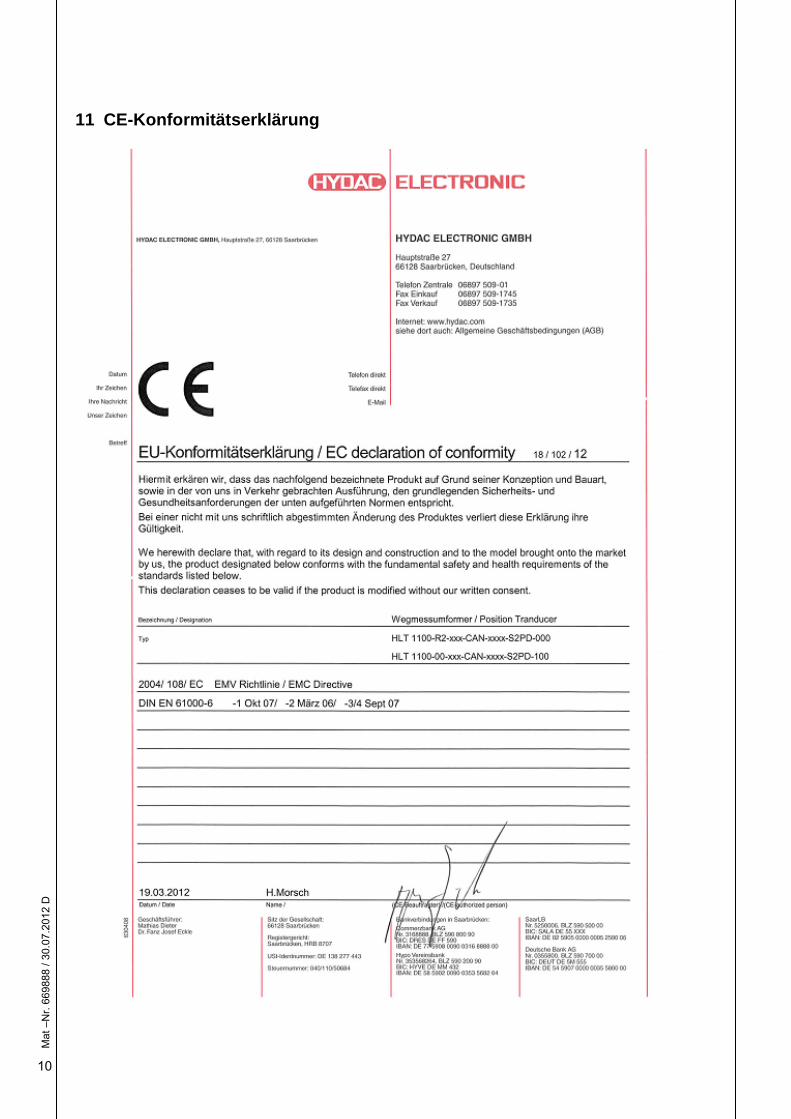
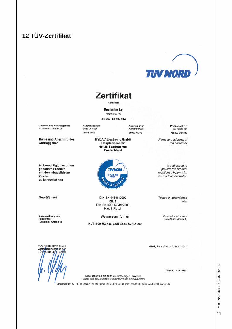
4.2 Konformität Die Konformität zu den relevanten Normen wird vom TÜV Nord Cert im Zertifikat Nr.: 44 207 12 397793 bestätigt.
4.3 Beschreibung der Sicherheitsfunktionen Der Wegmessumformer besitzt nur eine einzige Sicherheitsfunktion: Die Sicherheitsfunktion des Wegmessumformers besteht darin, innerhalb der spezifizierten Betriebsbedingungen und Eingangskenngrößen zu jeder Zeit zur Magnetposition wegabhängige Ausgangsdaten im Rahmen der spezifizierten Messgenauigkeit auszugeben. Im Fall eines erkannten internen Fehlers nimmt der Wegmessumformer den sicheren Zustand an.
Mat
–N
r. 66
9888
/ 30
.07.
2012
D
6
4.3.1 Ungestörter Betrieb Der ungestörte Betrieb ist dadurch gekennzeichnet, dass der Wegmessumformer SRDOs (Safety Relevant Data Object – CiA DS 304) erzeugt. Im SRDO ist die aktuelle Magnetposition als Digitalwert codiert.
4.3.2 Sicherer Zustand Der sichere Zustand ist dadurch gekennzeichnet, dass der Wegmessumformer keine SRDOs erzeugt. Die übergeordnete Steuerung erkennt diesen Zustand aufgrund der Vorgaben des Standards DS 304.
4.3.3 Gefährlicher Fehler Eine Gefährdungssituation kann entstehen, wenn der Wegmessumformer der übergeordneten Steuerung eine fehlerhafte Magnetposition signalisiert. Durch Schaltungs- und Software-Entwurf, Diagnosemaßnahmen und Auswahl der Bauteile wurde die Wahrscheinlichkeit für diesen Fehler minimiert (vgl. 9).
5 Spezifikation (Auszug) Die vollständige Spezifikation ist dem Benutzerhandbuch zu entnehmen
5.1 Diagnosezeiten
Diagnosezeit Wert Betriebsbereitschaft < 500 ms Diagnose-Intervall < 200 ms Prozess-Sicherheitszeit < 1000 ms
5.2 Elektrischer Anschluss
Versorgung Wert Versorgungsspannung (+UB) nominal 9 ... 36 V DC Restwelligkeit Versorgungsspannung < 250 mV Leistungsaufnahme < 2 W Elektrischer Anschluss (Kabel; 4-adrig)
braun: +UB weiß: 0V & CAN_GND grün: CANL gelb: CANH
M12x1 Flanschstecker an Einzeladern
Pin 1: N.C. Pin 2: +UB Pin 3: 0V & CAN_GND Pin 4: CANH Pin 5: CANL
Verpolungsschutz Überspannungsschutz Lastkurzschlussfestigkeit
vorhanden vorhanden vorhanden
Mat
–N
r. 66
9888
/ 30
.07.
2012
D
7
5.3 Umwelt
5.3.1 Temperaturbereich Umgebungsbedingung Wert Betriebstemperaturbereich - 40 ... 85 °C Lagertemperaturbereich - 40 ... 100 °C
5.3.2 Mechanisches Umfeld Umgebungsbedingung Wert Schutzklasse nach DIN 40050-9 IP 67
5.4 Eingangskenngrößen
Eingangskenngröße Wert Messlänge 200 ... 2500 mm Messbereichsanfang vor Montageflansch
≥ 30 mm
Messbereichsende vor Stabende ≥ 63 mm
5.5 Ausgangskenngrößen
Ausgangskenngröße Wert Ausgangssignal CANopen-Safety
DS 301, DS 302, DS 304, DS305 Encoder Profile DS 406
Baudrate 10 kbit/s ... 1 Mbit/s (DS 305) Auflösung 0,1 mm Wiederholbarkeit ≤ +/- 1 LSB Hysterese ≤ +/- 1 LSB Linearitätsabweichung ≤ +/- 0,02 % FS Genauigkeitsklasse (DIN 16086) ≤ +/- 0,2 % FS Reaktionszeit des Ausgangssignals ≤ 10 ms (0 ... 100 %)
6 Bedienelemente Der Wegmessumformer besitzt keine Bedienelemente. Entsprechend sind Benutzereingriffe weder möglich, noch erforderlich.
7 Inbetriebnahme Die Vorgaben im Benutzerhandbuch sind zu beachten. Kritisch sind insbesondere die Geometrie und Sauberkeit des Einbauraums, der einwandfreie Zustand der Dichtflächen und -elemente sowie der elektrische Anschluss.
Mat
–N
r. 66
9888
/ 30
.07.
2012
D
8
8 Intervall für Wiederholungsprüfungen Die Gebrauchsdauer des Wegmessumformers wird auf 20 Jahre festgelegt. Die Zuverlässigkeit der elektrischen, elektronischen und mechanischen Bauteile wird als ausreichend bewertet, um während der Gebrauchsdauer ohne Wiederholungsprüfung auskommen zu können.
9 Sicherheitstechnische Kennzahlen
9.1 Performance Level Gerät HLT 1100-R2-xxx-CAN-xxxx-S2PD-000 TÜV Nord Zertifikat 44 207 12 397793 Grundlage DIN EN ISO 13849-1:2008 – Teil 1 PL dArchitektur Kategorie 2 MTTFd 108,90 Jahre (hoch) DCavg 88,95 % (mittel) CCF 75 Punkte Gebrauchsdauer 20 Jahre
9.2 Safety Integrity Level Gerät HLT 1100-R2-xxx-CAN-xxxx-S2PD-000 TÜV Nord Zertifikat 44 207 12 397793 Grundlage DIN EN 61508:2001 SIL 2Klassifizierung Typ B System Architektur 1oo1D HFT 0 Anforderungsart kontinuierlich PFH 1,15 * 10-7 / h SFF 94,3 %
Mat
–N
r. 66
9888
/ 30
.07.
2012
D
9
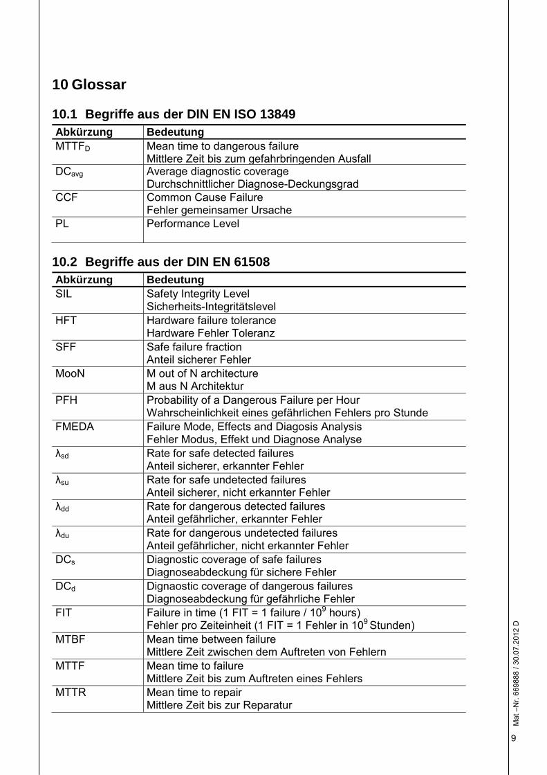
10 Glossar
10.1 Begriffe aus der DIN EN ISO 13849 Abkürzung Bedeutung MTTFD Mean time to dangerous failure
Mittlere Zeit bis zum gefahrbringenden AusfallDCavg Average diagnostic coverage
Durchschnittlicher Diagnose-Deckungsgrad CCF Common Cause Failure
Fehler gemeinsamer Ursache PL Performance Level
10.2 Begriffe aus der DIN EN 61508 Abkürzung Bedeutung SIL Safety Integrity Level
Sicherheits-Integritätslevel HFT Hardware failure tolerance
Hardware Fehler Toleranz SFF Safe failure fraction
Anteil sicherer Fehler MooN M out of N architecture
M aus N Architektur PFH Probability of a Dangerous Failure per Hour
Wahrscheinlichkeit eines gefährlichen Fehlers pro Stunde FMEDA Failure Mode, Effects and Diagosis Analysis
Fehler Modus, Effekt und Diagnose Analyse λsd Rate for safe detected failures
Anteil sicherer, erkannter Fehler λsu Rate for safe undetected failures
Anteil sicherer, nicht erkannter Fehler λdd Rate for dangerous detected failures
Anteil gefährlicher, erkannter Fehler λdu Rate for dangerous undetected failures
Anteil gefährlicher, nicht erkannter Fehler DCs Diagnostic coverage of safe failures
Diagnoseabdeckung für sichere Fehler DCd Dignaostic coverage of dangerous failures
Diagnoseabdeckung für gefährliche Fehler FIT Failure in time (1 FIT = 1 failure / 109 hours)
Fehler pro Zeiteinheit (1 FIT = 1 Fehler in 109 Stunden) MTBF Mean time between failure
Mittlere Zeit zwischen dem Auftreten von Fehlern MTTF Mean time to failure
Mittlere Zeit bis zum Auftreten eines Fehlers MTTR Mean time to repair
Mittlere Zeit bis zur Reparatur
Mat
–N
r. 66
9888
/ 30
.07.
2012
D
10
11 CE-Konformitätserklärung
Mat
–N
r. 66
9888
/ 30
.07.
2012
D
11
12 TÜV-Zertifikat
Mat
–N
r. 66
9888
/ 30
.07.
2012
D
12
HYDAC ELECTRONIC GMBH Hauptstr. 27 D-66128 Saarbrücken Germany Web: www.hydac.com E-Mail: [email protected] Tel.: +49 (0)6897 509-01 Fax.: +49 (0)6897 509-1726 HYDAC Service Für Fragen zu Reparaturen steht Ihnen der HYDAC Service zur Verfügung. HYDAC SERVICE GMBH Hauptstr. 27 D-66128 Saarbrücken Germany Tel.: +49 (0)6897 509-1936 Fax.: +49 (0)6897 509-1933 Anmerkung Die Angaben in dieser Dokumentation beziehen sich auf die beschriebenen Betriebsbedingungen und Einsatzfälle. Bei abweichenden Einsatzfällen und/oder Betriebsbedingungen wenden Sie sich bitte an die entsprechende Fachabteilung. Bei technischen Fragen, Hinweisen oder Störungen nehmen Sie bitte Kontakt mit Ihrer HYDAC-Vertretung auf. Technische Änderungen sind vorbehalten.
Par
t no.
: 669
888
/ 201
2/07
/30
E
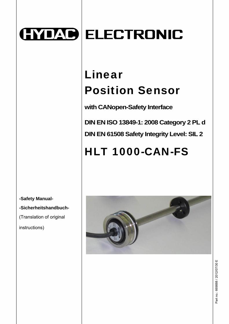
-Safety Manual-
-Sicherheitshandbuch-
(Translation of original
instructions)
Linear Position Sensor
with CANopen-Safety Interface
DIN EN ISO 13849-1: 2008 Category 2 PL d
DIN EN 61508 Safety Integrity Level: SIL 2
HLT 1000-CAN-FS

Par
t no.
: 669
888
/ 201
2/07
/30
E
2
Par
t no.
: 669
879
/ 201
2/07
/30
E
3
Contents
1 General data 4
1.1 Author, version, date, document name, file name 4 1.2 Version history and revision notes 4
2 Scope 4
3 Product description 5
4 Functional safety 5 4.1 Relevant standards 5 4.2 Conformity 5 4.3 Description of the safety functions 5 4.3.1 Normal operation 6 4.3.2 Safe state 6 4.3.3 Dangerous failures 6
5 Specification (extract) 6 5.1 Diagnostic times 6 5.2 Electrical connection 6 5.3 Environment 7 5.3.1 Temperature range 7 5.3.2 Mechanical environment 7 5.4 Input data 7 5.5 Output data 7
6 Operating elements 7
7 Commissioning 7
8 Interval between repeat testing 8
9 Safety-related information 8 9.1 Performance level 8 9.2 Safety integrity level 8
10 Glossary 9
10.1 Terms from DIN EN ISO 13849 9 10.2 Terms from DIN EN 61508 9
11 CE conformity declaration 10
12 TÜV Certificate 11
Par
t no.
: 669
888
/ 201
2/07
/30
E
4
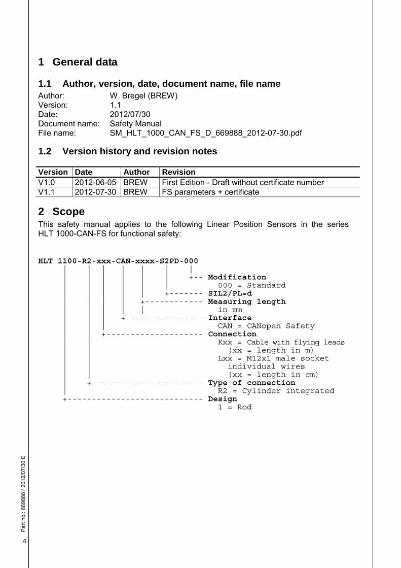
1 General data
1.1 Author, version, date, document name, file name Author: W. Bregel (BREW) Version: 1.1 Date: 2012/07/30 Document name: Safety Manual File name: SM_HLT_1000_CAN_FS_D_669888_2012-07-30.pdf
1.2 Version history and revision notes Version Date Author RevisionV1.0 2012-06-05 BREW First Edition - Draft without certificate number V1.1 2012-07-30 BREW FS parameters + certificate
2 Scope This safety manual applies to the following Linear Position Sensors in the series HLT 1000-CAN-FS for functional safety:
HLT 1100-R2-xxx-CAN-xxxx-S2PD-000 | | | | | | | | | | | | | +-- Modification | | | | | | 000 = Standard | | | | | +------- SIL2/PL=d | | | | +------------ Measuring length | | | | | in mm | | | +---------------- Interface | | | CAN = CANopen Safety | | +-------------------- Connection | | Kxx = Cable with flying leads | | (xx = length in m) | | Lxx = M12x1 male socket | | individual wires | | (xx = length in cm) | +----------------------- Type of connection | R2 = Cylinder integrated +---------------------------- Design 1 = Rod
Par
t no.
: 669
888
/ 201
2/07
/30
E
5
3 Product description The linear position sensor series HLT 1000-CAN-FS has been specially developed for hydraulic cylinders, e.g. in mobile applications, and provides reliable monitoring of the piston rod position in hydraulic cylinders. The HLT 1000-CAN-FS is based on the robust, long-lasting and wear-free principle of magnetostriction. The housing shape and the geometry are designed in such a way that it is impossible to install it incorrectly in the cylinder. A CANopen-Safety interface is available for incorporation in modern controls. The HLT 1000-CAN-FS linear position sensor is specially designed for use in safety circuits/safety functions as part of the functional safety of machines up to SIL2 (DIN EN 61508) or PL = 'd' Cat 2 (DIN EN ISO 13849-1:2008). The linear position sensor is designed to be a sensor element (SRP/CS) in electronic control systems (E/E/PE system).
4 Functional safety
4.1 Relevant standards Performance Level
DIN EN ISO 13849-1: 2008-1 Safety of machinery – Safety-related parts of control systems - Part 1: General principles for design
Safety integrity level DIN EN 61508: 2001 Functional safety of safety-related electrical, electronic and programmable electronic control systems
CANopen (CAN in Automation - CiA)
DS 301, DS 302, DS 304, DS 305, DS 406
4.2 Conformity Conformity to the relevant standards is certified by TÜV Nord in certificate no: 44 207 12 397793.
4.3 Description of the safety functions The linear position sensor has just one safety function: The safety function of the linear position sensor consists in at any time transmitting distance-related output values to the magnet position within the specified measuring accuracy, within the specified operating conditions and input parameters. In case of internal error detection, the linear position sensor goes into the "safe state".
Par
t no.
: 669
888
/ 201
2/07
/30
E
6
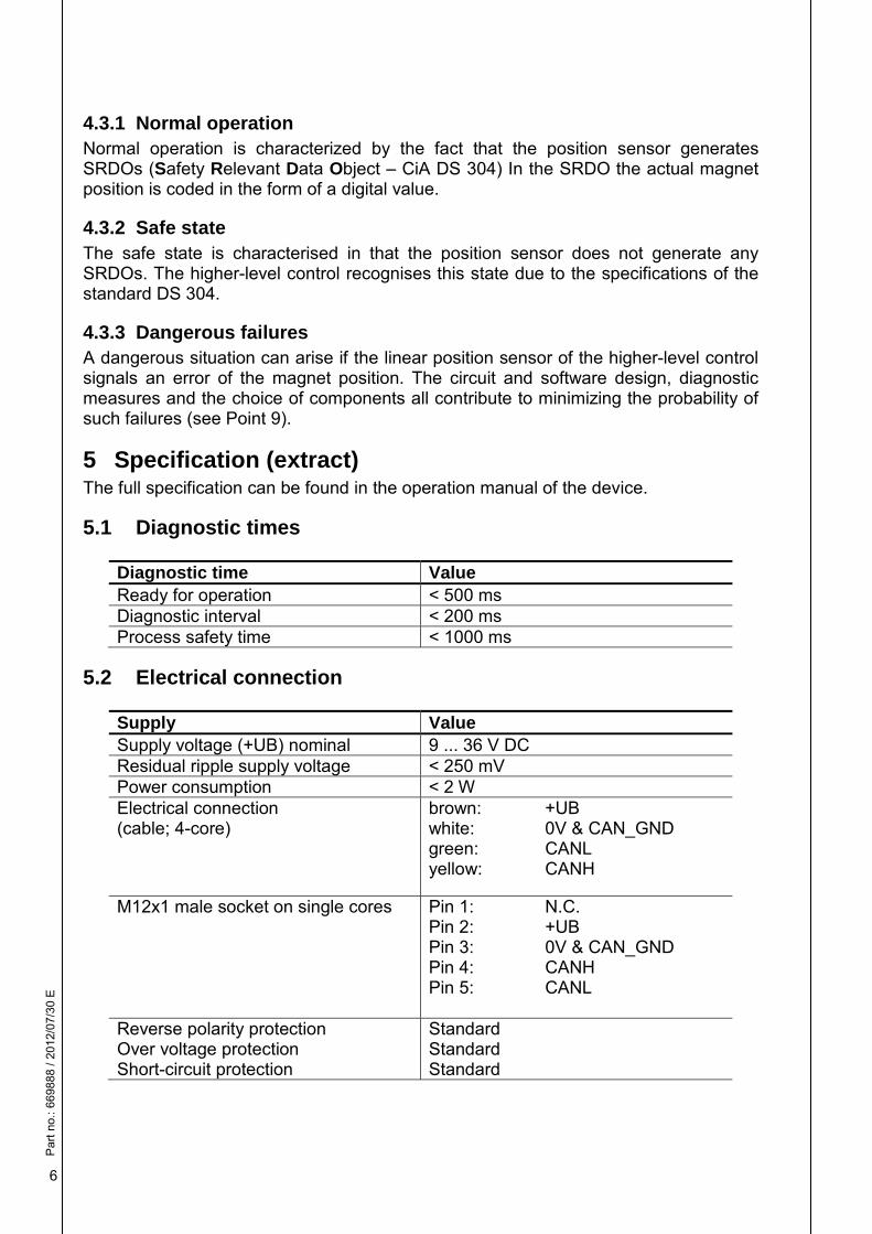
4.3.1 Normal operation Normal operation is characterized by the fact that the position sensor generates SRDOs (Safety Relevant Data Object – CiA DS 304) In the SRDO the actual magnet position is coded in the form of a digital value.
4.3.2 Safe state The safe state is characterised in that the position sensor does not generate any SRDOs. The higher-level control recognises this state due to the specifications of the standard DS 304.
4.3.3 Dangerous failures A dangerous situation can arise if the linear position sensor of the higher-level control signals an error of the magnet position. The circuit and software design, diagnostic measures and the choice of components all contribute to minimizing the probability of such failures (see Point 9).
5 Specification (extract) The full specification can be found in the operation manual of the device.
5.1 Diagnostic times
Diagnostic time Value Ready for operation < 500 ms Diagnostic interval < 200 ms Process safety time < 1000 ms
5.2 Electrical connection
Supply Value Supply voltage (+UB) nominal 9 ... 36 V DC Residual ripple supply voltage < 250 mV Power consumption < 2 W Electrical connection (cable; 4-core)
brown: +UB white: 0V & CAN_GND green: CANL yellow: CANH
M12x1 male socket on single cores Pin 1: N.C. Pin 2: +UB Pin 3: 0V & CAN_GND Pin 4: CANH Pin 5: CANL
Reverse polarity protection Over voltage protection Short-circuit protection
Standard Standard Standard
Par
t no.
: 669
888
/ 201
2/07
/30
E
7
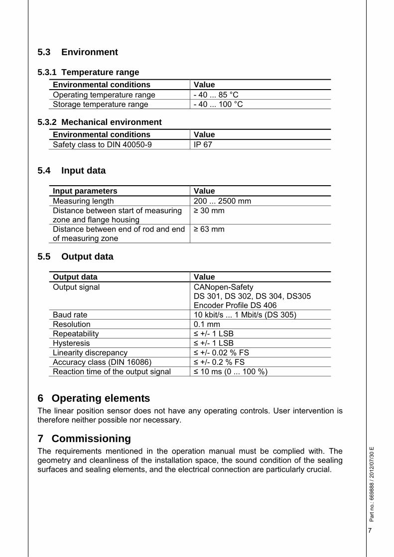
5.3 Environment
5.3.1 Temperature range Environmental conditions Value Operating temperature range - 40 ... 85 °C Storage temperature range - 40 ... 100 °C
5.3.2 Mechanical environment Environmental conditions Value Safety class to DIN 40050-9 IP 67
5.4 Input data
Input parameters Value Measuring length 200 ... 2500 mm Distance between start of measuring zone and flange housing
≥ 30 mm
Distance between end of rod and end of measuring zone
≥ 63 mm
5.5 Output data
Output data Value Output signal CANopen-Safety
DS 301, DS 302, DS 304, DS305 Encoder Profile DS 406
Baud rate 10 kbit/s ... 1 Mbit/s (DS 305) Resolution 0.1 mm Repeatability ≤ +/- 1 LSB Hysteresis ≤ +/- 1 LSB Linearity discrepancy ≤ +/- 0.02 % FS Accuracy class (DIN 16086) ≤ +/- 0.2 % FS Reaction time of the output signal ≤ 10 ms (0 ... 100 %)
6 Operating elements The linear position sensor does not have any operating controls. User intervention is therefore neither possible nor necessary.
7 Commissioning The requirements mentioned in the operation manual must be complied with. The geometry and cleanliness of the installation space, the sound condition of the sealing surfaces and sealing elements, and the electrical connection are particularly crucial.

Par
t no.
: 669
888
/ 201
2/07
/30
E
8
8 Interval between repeat testing The operating life of the position sensor is defined as 20 years. The reliability of the electrical, electronic and mechanical components is such that no repeat testing is required during the unit's operating life.
9 Safety-related information
9.1 Performance level Instrument HLT 1100-R2-xxx-CAN-xxxx-S2PD-000 TÜV Nord certificate 44 207 12 397793 Based on DIN EN ISO 13849-1:2008 – Part 1 PL dArchitecture Category 2 MTTFd 108.90 years (high) DCavg 88.95 % (medium) CCF 75 Points Operating life 20 years
9.2 Safety integrity level Instrument HLT 1100-R2-xxx-CAN-xxxx-S2PD-000 TÜV Nord certificate 44 207 12 397793 Based on DIN EN 61508:2001 SIL 2Classification Type B System Architecture 1oo1D HFT 0 Demand mode continuous PFH 1.15 * 10-7 / h SFF 94.3 %
Par
t no.
: 669
888
/ 201
2/07
/30
E
9
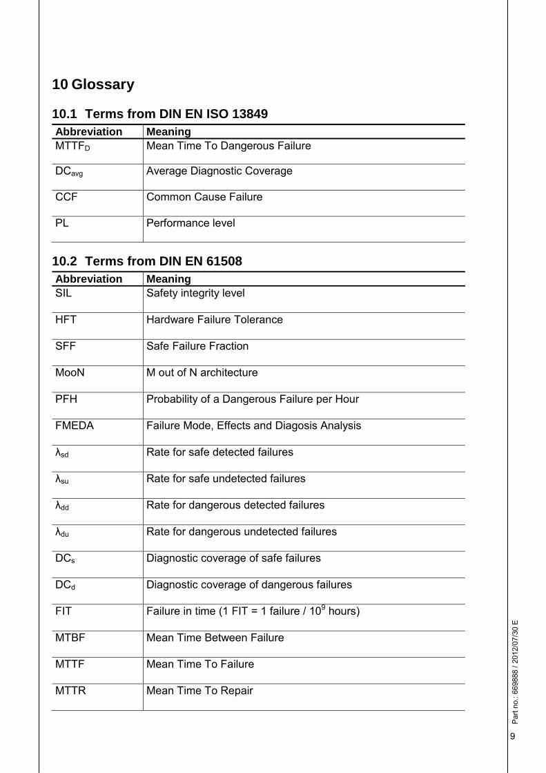
10 Glossary
10.1 Terms from DIN EN ISO 13849 Abbreviation Meaning MTTFD Mean Time To Dangerous Failure
DCavg Average Diagnostic Coverage
CCF Common Cause Failure
PL Performance level
10.2 Terms from DIN EN 61508 Abbreviation Meaning SIL Safety integrity level
HFT Hardware Failure Tolerance
SFF Safe Failure Fraction
MooN M out of N architecture
PFH Probability of a Dangerous Failure per Hour
FMEDA Failure Mode, Effects and Diagosis Analysis
λsd Rate for safe detected failures
λsu Rate for safe undetected failures
λdd Rate for dangerous detected failures
λdu Rate for dangerous undetected failures
DCs Diagnostic coverage of safe failures
DCd Diagnostic coverage of dangerous failures
FIT Failure in time (1 FIT = 1 failure / 109 hours)
MTBF Mean Time Between Failure
MTTF Mean Time To Failure
MTTR Mean Time To Repair
Par
t no.
: 669
888
/ 201
2/07
/30
E
10
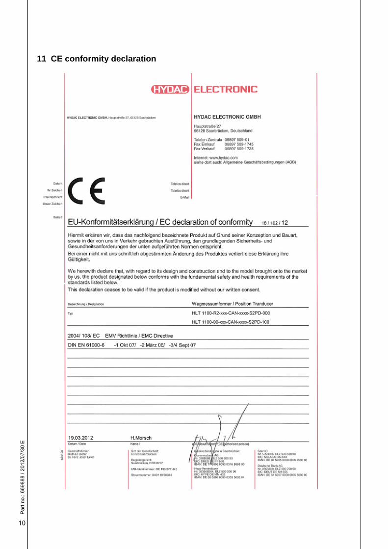
11 CE conformity declaration

Par
t no.
: 669
888
/ 201
2/07
/30
E
11
12 TÜV Certificate
Par
t no.
: 669
888
/ 201
2/07
/30
E
12
HYDAC ELECTRONIC GMBH Hauptstr. 27 D-66128 Saarbrücken Germany Web: www.hydac.com Email: [email protected] Tel.: +49 (0)6897 509-01 Fax: +49 (0)6897 509-1726 HYDAC Service For enquiries regarding repairs, please contact HYDAC Service. HYDAC SERVICE GMBH Hauptstr. 27 D-66128 Saarbrücken Germany Tel.: +49 (0)6897 509-1936 Fax: +49 (0)6897 509-1933 NOTE The information in this manual relates to the operating conditions and applications described. For applications and operating conditions not described, please contact the relevant technical department. If you have any questions, suggestions, or encounter any problems of a technical nature, please contact your Hydac representative. Subject to technical modifications.


![LOW PRESSURE FILTERS NF MMP Series - hydac-na.com · D182 PN#02081318 / 03.16 / FIL1505-1696 LOW PRESSURE FILTERS Size 5210 Weight (lbs.) 287 Dimensions shown are [inches] millimeters](https://img.pdfslide.us/doc/110x75/5bef866409d3f2ec148b8ff2/low-pressure-filters-nf-mmp-series-hydac-na-d182-pn02081318-0316-fil1505-1696.jpg)