Embed Size (px)
Citation preview
FCU 1000 Series FluidControl Unit
Operating and Maintenance Instructions English (translation of original instructions)
Valid from firmware versions V 2.00 up
Document no.: 3371346d

FCU 1000 Series Trademarks
HYDAC FILTER SYSTEMS GMBH en Page 2 / 104
BeWa_FCU1000_3371346d en-us 2010-11-24.doc 2010-11-24
Trademarks
The trademarks of other companies are exclusively used for the products of those companies.
Copyright © 2010 by HYDAC FILTER SYSTMES GMBH all rights reserved
All rights reserved. This manual may not be reproduced in part or whole without the express written consent of HYDAC FILTER SYSTEMS GMBH. Contraventions are liable to compensation.
Exclusion of Liability
We made every endeavor to ensure the accuracy of the contents of this document. However, errors cannot be ruled out. Consequently, we accept no liability for such errors as may exist nor for any damage or loss whatsoever which may arise as a result of such errors. We welcome any suggestions for improvements.
All details are subject to technical modifications.
Technical specifications are subject to change without notice.
HYDAC FILTER SYSTEMS GMBHPostfach 12 5166273 Sulzbach / Saar
Germany
Documentation Representative
Mr. Günter Harge
c/o HYDAC International GmbH, Industriegebiet, 66280 Sulzbach / Saar
Telephone: ++49 (0)6897 509 1511
Fax: ++49 (0)6897 509 1394
E-Mail: [email protected]

FCU 1000 Series Contents
HYDAC FILTER SYSTEMS GMBH en Page 3 / 104
BeWa_FCU1000_3371346d en-us 2010-11-24.doc 2010-11-24
Contents
Trademarks ...............................................................................................................2
Documentation Representative...............................................................................2
Contents....................................................................................................................3
What's New — Document History...........................................................................6
Preface ......................................................................................................................7
Technical Support...................................................................................................8 Modifications to the Product ...................................................................................8 Warranty .................................................................................................................8 Using the Documentation .......................................................................................9
Safety Information and Instructions.....................................................................10
Obligations and Liability........................................................................................10 Explanation of Symbols and Warnings, etc. .........................................................11 Proper/Designated Use ........................................................................................11 Improper Use or Use Deviating from Intended Use..............................................12 Informal Safety Precautions..................................................................................12 What to Do in Case of Emergency .......................................................................12 Training and Instruction of Personnel ...................................................................13
Transporting the FCU ............................................................................................14
Storing the FCU ......................................................................................................15
Decoding the model code label ............................................................................16
Checking the scope of delivery ............................................................................17
What the FCU 1000 can do ....................................................................................18
Restrictions on the use of the FCU 1000..............................................................19
Counting particles in the FCU 1000......................................................................20
How the FCU 1000 functions.................................................................................21
User interface of the FCU 1000 ............................................................................22 Dimensions of the FCU 1000................................................................................23 Hydraulic diagram.................................................................................................24
Using the BatteryPack (accessory) ......................................................................25
Preparing the FCU for measurement....................................................................28
Connecting/disconnecting the FCU electrically.....................................................28 Connecting/disconnecting the OUTLET hose.......................................................29 Selecting the measurement point .........................................................................30 Select the measurement method according to the pressure involved ..................31
Measuring up to max. 45 bar / 650 psi..................................................................32
Measuring in the range 5 to 345 bar / 217 to 5000 psi.........................................35
Measuring from unpressurized containers..........................................................38
Operating the FCU..................................................................................................40
Display and keypad elements...............................................................................40
Clicking through the display .................................................................................42
ISO.SAE display................................................................................................42
FCU 1000 Series Contents
HYDAC FILTER SYSTEMS GMBH en Page 4 / 104
BeWa_FCU1000_3371346d en-us 2010-11-24.doc 2010-11-24
ISO.SAE display................................................................................................43
Measured variables ................................................................................................44
Measured variable "ISO"...................................................................................44 Measured variable "SAE"..................................................................................44 Measured variable "NAS"..................................................................................44 Measured variable "Water saturation"...............................................................44 Measured variable "Temperature".....................................................................45
Service variables ..................................................................................................45 Service variables "Flow"....................................................................................45 Service variables "Drive" ...................................................................................45
FCU configuration menus .....................................................................................46
Power Up Menu ....................................................................................................46 DAT.TIM – date / time .......................................................................................47 ADRESS - Bus address ....................................................................................47 DEL.MEM – Delete Memory .............................................................................48 M.TIME – Measurement Time...........................................................................48 CALIB – Select calibration type.........................................................................49 DFAULT – reset to factory settings ...................................................................49 CANCEL............................................................................................................50 SAVE – store data.............................................................................................50
Measuring Menu ...................................................................................................51 RECORD - recording measurements................................................................52 MEMORY – display free memory......................................................................53 ED.MPNT – Change the name of measurement points....................................54 TP.UNIT – change the temperature units °C / °F..............................................55 CANCEL............................................................................................................55 SAVE - save data..............................................................................................55
Performing a measurement...................................................................................56
Restrictions pertaining to use ...............................................................................56
Internal measurement memory .............................................................................56
DATA - interface .....................................................................................................57
Connecting the FCU with CSI-B-2 kit ...................................................................57 Pins used on the DATA interface (HYDAC Sensor Interface – HSI) ....................57 Connecting the FCU with HMG 510 / HMG 3000 .................................................58
USB interface..........................................................................................................59
Copying measurements onto a USB data stick ....................................................59 Data transmission failed - "ERROR COPY"..........................................................61
Bluetooth interface.................................................................................................62
Installing the Bluetooth USB adaptor ....................................................................63 Guarantee and liability for the USB adapter......................................................63
Connecting the FCU via Bluetooth .......................................................................63
Evaluating stored records .....................................................................................64
Directories to store the records by measurement points ......................................64 Record file names.................................................................................................64 Evaluating the file containing the measurements .................................................65
FCU 1000 Series Contents
HYDAC FILTER SYSTEMS GMBH en Page 5 / 104
BeWa_FCU1000_3371346d en-us 2010-11-24.doc 2010-11-24
The measurements are shown as dates ...........................................................67
Measurement value readouts with FluMoS..........................................................68
Preparing the FCU for transport ...........................................................................69
Performing maintenance ......................................................................................72
Cleaning the FCU .................................................................................................72 Rinsing the FCU ...................................................................................................72 Clean the suction strainer. ....................................................................................75 Checking the high pressure adaptor.....................................................................78
Cleaning / changing the sieve in the high pressure adapter .............................79 Cleaning / changing the strainer in the high pressure adapter..........................80
FCU status messages / error messages .............................................................81
Restart / Resetting the FCU...................................................................................84
Disposing of the FCU.............................................................................................84
Spare Parts List ......................................................................................................85
Accessories for the FCU.......................................................................................86
Overview - ISO 4406 / SAE AS 4059 and NAS 1638 classes...............................89
ISO 4406:1999......................................................................................................89 ISO 4406 table ..................................................................................................89 Overview of the differences between ISO 4406:1987 and ISO 4406:1999 .........................................................................................................90
SAE AS 4059........................................................................................................91 SAE AS 4059 table ...........................................................................................91 Cleanliness codes according to SAE ................................................................91
Absolute particle count larger than a defined particle size ............................91 Specifying a cleanliness class for each particle size .....................................92 Specifying the highest cleanliness code measured .......................................92
NAS 1638 .............................................................................................................92
Checking the measuring accuracy of the FCU....................................................93
Calibrating the FCU................................................................................................93
Customer service ...................................................................................................94
Germany ...............................................................................................................94 USA ......................................................................................................................94 Australia................................................................................................................94 Brazil .....................................................................................................................95
Factory default settings.........................................................................................95
Technical Data ........................................................................................................96
Model Code .............................................................................................................98
Compatible USB sticks - overview .......................................................................99
EC declaration of conformity ..............................................................................100

FCU 1000 Series What's New — Document History
HYDAC FILTER SYSTEMS GMBH en Page 6 / 104
BeWa_FCU1000_3371346d en-us 2010-11-24.doc 2010-11-24
What's New — Document History
The index is featured on the cover sheet of the operating and maintenance manual and in the lower left corner of each page after the part number.
Index "a" - from firmware version V 1.10
- Change to the items delivered
- Change of Bluetooth device name to "FCU1310"
Index "b" — from firmware version V 2.00
- Change to the items delivered
- "USB connection" chapter added
- Additions made to user interface chapters
- Additions made to "BatteryPack" chapter
Index "c"
- Index adapted
Index "d"
- Restrictions on use of fluid with flash point < 55°C added
- Spare parts list adapted
- "Transporting FCU“ updated
- Filling the hose lines before measuring is no longer necessary.
FCU 1000 Series Preface
HYDAC FILTER SYSTEMS GMBH en Page 7 / 104
BeWa_FCU1000_3371346d en-us 2010-11-24.doc 2010-11-24
Preface
For you, as the owner of a product manufactured by us, we have produced this manual, comprising the most important instructions for its operation and maintenance.
It is intended to help you become acquainted with the ins and outs of the product and use it properly.
You should keep it in the vicinity of the product so it is always at your fingertips.
Sometimes the information contained in the documentation cannot always keep up with changes made to the product as we attach considerable importance to keeping our products cutting-edge. Consequently, there might be deviations in technical details, illustrations and dimensions.
If you discover errors while reading the documentation or have suggestions or other useful information, please don’t hesitate to contact us:
HYDAC FILTER SYSTEMS GMBHTechnische DokumentationPostfach 12 5166273 Sulzbach / Saar
Germany
We look forward to receiving your input.
Our motto: “Putting experience into practice”
FCU 1000 Series Preface
HYDAC FILTER SYSTEMS GMBH en Page 8 / 104
BeWa_FCU1000_3371346d en-us 2010-11-24.doc 2010-11-24
Technical Support If you have any questions, suggestions, or encounter any problems of a technical nature, please don't hesitate to contact us. When contacting us, please always include the model/type designation and article no. of the product:
Fax: ++49 (0) 6897 / 509 - 846
E-mail: [email protected]
Modifications to the Product We would like to point out that changes to the product (e.g. purchasing options, etc.) may result in the information in the operating instructions no longer being completely accurate or sufficient.
When making modifications or performing repair work to components affecting the safety of the product, the product may not be put back into operation until it has been examined and released by a HYDAC representative.
Please notify us immediately of any modifications made to the product whether by you or a third party.
Warranty For the warranty provided by us, please refer to the General Terms of Sale and Delivery of HYDAC FILTER SYSTEMS GMBH.
Refer to these at www.hydac.com ð General terms and conditions.
FCU 1000 Series Preface
HYDAC FILTER SYSTEMS GMBH en Page 9 / 104
BeWa_FCU1000_3371346d en-us 2010-11-24.doc 2010-11-24
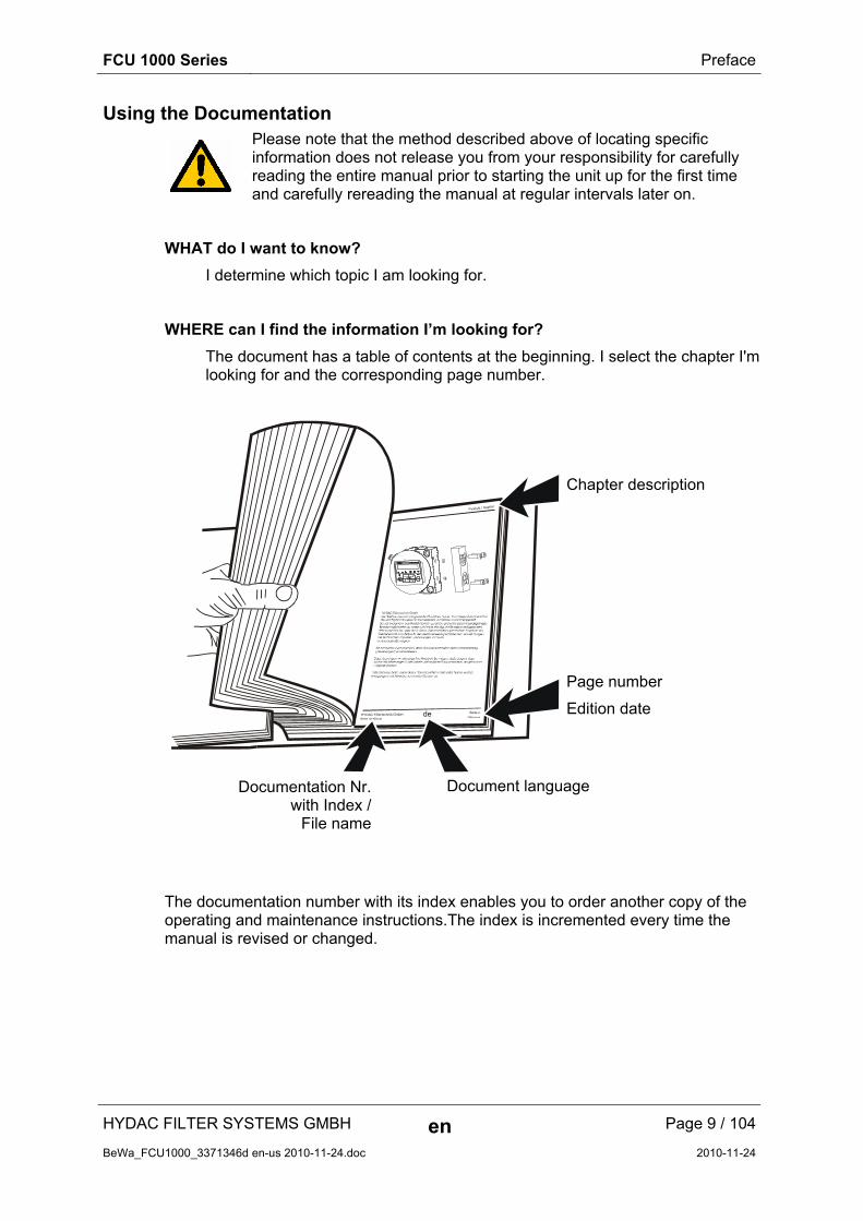
Using the Documentation
Please note that the method described above of locating specific information does not release you from your responsibility for carefully reading the entire manual prior to starting the unit up for the first time and carefully rereading the manual at regular intervals later on.
WHAT do I want to know?
I determine which topic I am looking for.
WHERE can I find the information I’m looking for?
The document has a table of contents at the beginning. I select the chapter I'm looking for and the corresponding page number.
deHYDAC Filtertechnik GmbHBeWa 123456a de
Seite x
Produkt / Kapitel
200x-xx-xx
The documentation number with its index enables you to order another copy of the operating and maintenance instructions.The index is incremented every time the manual is revised or changed.
Chapter description
Page number
Edition date
Document language Documentation Nr.with Index /
File name
FCU 1000 Series Safety Information and Instructions
HYDAC FILTER SYSTEMS GMBH en Page 10 / 104
BeWa_FCU1000_3371346d en-us 2010-11-24.doc 2010-11-24
Safety Information and Instructions
These operating instructions contain the key instructions for properly and safely operating the FCU.
Obligations and Liability
The basic prerequisite for the safe and proper handling and operation of the FCU is knowledge of the safety instructions and warnings.
These operating instructions in general, and the safety precautions in particular, are to be adhered by all those who work with the FCU.
Adherence is to be maintained to pertinent accident prevention regulations applicable at the site where the product is used.
The safety precautions listed here are limited solely to using the FCU.
The FCU has been designed and constructed in accordance with the current state of the art and recognized safety regulations. Nevertheless, hazards may be posed to the life and limb of the individual using the product or to third parties. Risk of damage may be posed to the product or other equipment and property.
The FCU is only to be used as follows:
Only for proper or designated use.
Only when in safe, perfect condition.
Immediately remedy any malfunctions that might impair safety.
Our General Terms and Conditions apply. They are made available to the owner upon concluding purchase of the unit at the latest. Any and all warranty and liability claims for personal injuries and damage to property shall be excluded in the event they are attributable to one or more of the following causes.

FCU 1000 Series Safety Information and Instructions
HYDAC FILTER SYSTEMS GMBH en Page 11 / 104
BeWa_FCU1000_3371346d en-us 2010-11-24.doc 2010-11-24
Explanation of Symbols and Warnings, etc.
The following designations and symbols are used in this manual to designate hazards, etc.:
DANGER DANGER denotes situations which can lead to death if safety precautions are not observed.
WARNING WARNING denotes situations which can lead to death if safety precautions are not observed.
CAUTION CAUTION denotes situations which can lead to severe injuries if safety precautions are not observed.
NOTICE NOTICE denotes situations which can lead to property damage if instructions are not followed.
Proper/Designated Use
The fluid control unit, FCU, was developed to intermittently monitor solid particle contamination, temperature und % saturation level in hydraulic systems.
Analyzing the size and quantity of contamination enables quality standards to be verified and documented and the requisite optimization measures to be implemented.
Any other use shall be deemed to be improper and not in keeping with the product's designated use.
Proper or designated use of the product extends to the following:
Typical application: Short-time measurement of system cleanliness
Maintaining adherence to all the instructions contained herein.
Performing requisite inspection and maintenance work.

FCU 1000 Series Safety Information and Instructions
HYDAC FILTER SYSTEMS GMBH en Page 12 / 104
BeWa_FCU1000_3371346d en-us 2010-11-24.doc 2010-11-24
Improper Use or Use Deviating from Intended Use
Improper use may result in hazards like the following:
Use of the FCU 1000 for permanent monitoring (i.e. continuous operation)
Improper connection of the FCU pressure or return hoses.
It is not permitted to operate the FCU1000 on a measurement point where the pressure exceeds 345 bar.
Operation of the FCU on board networks without central "Load Dump" fuse.
Informal Safety Precautions
Always keep the operating and maintenance instructions near the measurement device.
In addition to the manual, the general and local regulations concerning accident prevention and protection of the environment should be available and observed.
Ensure that all information relating to safety and potential hazards of the FCU are kept in a legible condition. Replace them if necessary.
Check the hoses and connectors for leaks on a daily basis.
The product is to be checked once a day for visible external damage and for the proper functioning of the safety devices.
WARNING Hydraulic systems are under pressure
Danger of bodily injury
► Depressurize the system before performing any work on it.
What to Do in Case of Emergency
In the event of an emergency, disconnect the FCU from the power supply and from the hydraulic system.

FCU 1000 Series Safety Information and Instructions
HYDAC FILTER SYSTEMS GMBH en Page 13 / 104
BeWa_FCU1000_3371346d en-us 2010-11-24.doc 2010-11-24
Training and Instruction of Personnel
The owner is obliged to only let persons work on the FCU, who:
are familiar with the fundamental occupational safety and accident prevention regulations and have been properly instructed in the use of the FCU.
have read and understood these operating instructions.
Only properly trained and instructed personnel may work with the FCU.
The areas of responsibility of your staff must be established in a clear-cut manner.
Staff who are still being trained may only work on the FCU when supervised by a suitably experienced person.
Ind
ivid
ual
s
Ind
ivid
ual
s u
nd
erg
oin
g
trai
nin
g
Ind
ivid
ual
s w
ith
te
chn
ical
tra
inin
g/
eng
inee
rin
g
bac
kgro
un
d
Ele
ctri
cian
Su
per
viso
r w
ith
th
e ap
pro
pri
ate
auth
ori
ty
Activity
Packing Transportation
X X X
Start up X X X
Operation X X X X
Troubleshooting/ locating the source of malfunction
X X X
Remedying of mechanical faults X X
Remedying of electrical faults X X
Maintenance X X X X
Repair work X
Decommissioning/storage X X X X

FCU 1000 Series Transporting the FCU
HYDAC FILTER SYSTEMS GMBH en Page 14 / 104
BeWa_FCU1000_3371346d en-us 2010-11-24.doc 2010-11-24
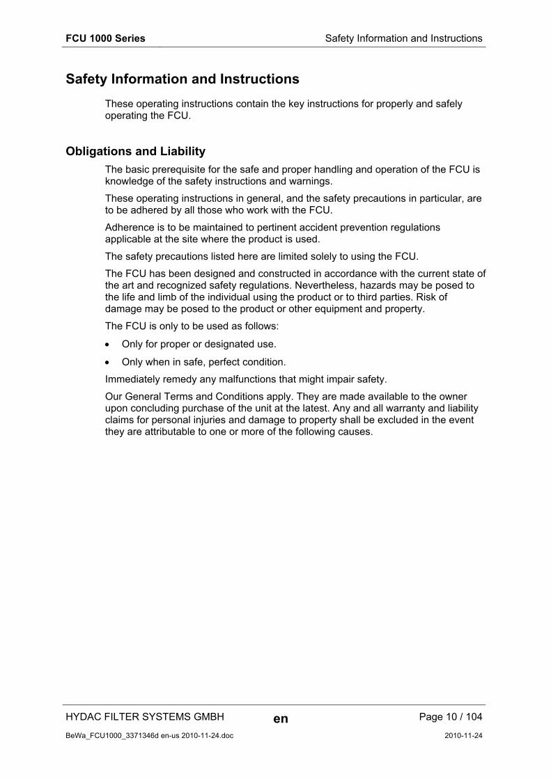
Transporting the FCU
Transport the FCU only when it is closed position; carry it flat or by the handle.

FCU 1000 Series Storing the FCU
HYDAC FILTER SYSTEMS GMBH en Page 15 / 104
BeWa_FCU1000_3371346d en-us 2010-11-24.doc 2010-11-24
Storing the FCU
Drain and rinse the FCU completely before putting it into storage. See page 72 for details on rinsing the FCU.
Observe the following storage conditions:
Storage temperature: -40 … +80°C / -40 … +176°F
Relative humidity: max. 90%, non-condensing
Store the FCU closed and in a horizontal position in a dry, clean place. If stored in an vertical position, the FCU must not be exposed to any shaking or vibration.

FCU 1000 Series Decoding the model code label
HYDAC FILTER SYSTEMS GMBH en Page 16 / 104
BeWa_FCU1000_3371346d en-us 2010-11-24.doc 2010-11-24
Decoding the model code label
For identification of the FluidControl Unit, see the type label. The label shows product ID and major technical application data.
See page 98.for more details on the model code.
FCU 1000 Series Checking the scope of delivery
HYDAC FILTER SYSTEMS GMBH en Page 17 / 104
BeWa_FCU1000_3371346d en-us 2010-11-24.doc 2010-11-24
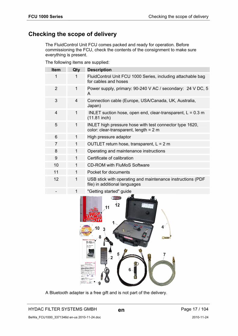
Checking the scope of delivery
The FluidControl Unit FCU comes packed and ready for operation. Before commissioning the FCU, check the contents of the consignment to make sure everything is present.
The following items are supplied:
Item Qty Description
1 1 FluidControl Unit FCU 1000 Series, including attachable bag for cables and hoses
2 1 Power supply, primary: 90-240 V AC / secondary: 24 V DC, 5 A
3 4 Connection cable (Europe, USA/Canada, UK, Australia, Japan)
4 1 INLET suction hose, open end, clear-transparent, L = 0.3 m (11.81 inch)
5 1 INLET high pressure hose with test connector type 1620, color: clear-transparent, length = 2 m
6 1 High pressure adaptor
7 1 OUTLET return hose, transparent, L = 2 m
8 1 Operating and maintenance instructions
9 1 Certificate of calibration
10 1 CD-ROM with FluMoS Software
11 1 Pocket for documents
12 1 USB stick with operating and maintenance instructions (PDF file) in additional languages
- 1 "Getting started" guide
A Bluetooth adapter is a free gift and is not part of the delivery.

FCU 1000 Series What the FCU 1000 can do
HYDAC FILTER SYSTEMS GMBH en Page 18 / 104
BeWa_FCU1000_3371346d en-us 2010-11-24.doc 2010-11-24
What the FCU 1000 can do
The FCU 1000 is a portable service unit for hydraulic systems for intermittent measurement of the particulate contamination, the moisture content in % saturation and the temperature of the fluid.
The integral pump and hoses supplied can be used on:
Control circuits
Pressure circuits
non-pressurized tanks
Applications for the FCU include the servicing and repair of mobile hydraulic systems.
The internal data memory enables measurements to be recorded together with a time-stamp.
The USB interface can be used to copy all measurements to a USB memory stick, for subsequent evaluation on a PC using Excel or the fluid monitoring software FluMoS Light.
Additional features include:
Optical measurement of the degree of solid particle contamination
Capacitive measurement of the relative humidity in % saturation.
Resistive measurement of the temperature
Applicable for hydraulic fluids (up to ISO VG 68) 10 … 350 mm²/s / 16 … 1622 Sus
Automatic measurement and display of cleanliness ratings in accordance with:
ISO 4406:1987; NAS 1638
ISO 4406:1999; SAE AS 4059 (D)
Measurement accuracy +/- ½ ISO code in the calibrated range
Supply voltage of 24 V DC / 4 A for operation on mobile machine on-board power supplies
Network adapter 90 - 240 V AC / 24 V DC 5 A included in the scope of delivery
Operating pressure without high-pressure adapter max. 45 bar / max. 650 psi, Operating pressure with high-pressure adapter max. 345 bar / max. 5000 psi
Integrated pump for the automatic control of oil flow

FCU 1000 Series What the FCU 1000 can do
HYDAC FILTER SYSTEMS GMBH en Page 19 / 104
BeWa_FCU1000_3371346d en-us 2010-11-24.doc 2010-11-24
Restrictions on the use of the FCU 1000
NOTICE
Impermissible operating conditions
The FCU will be destroyed
► Use the FCU with mineral oils or mineral oil-based raffinates whose flash point is higher than 55°C/131°F.
► Observe the permissible viscosity range (up to ISO VG 68): 10 ... 350 mm²/s or 46 ... 1622 SUS
► Only operate the FCU 1000 for brief periods of time (S4 to DIN EN 60034 / VDE 0530).
► When the pump has been operating for 30 minutes, shut off the FCU 1000 for at least 10 minutes to cool down.
NOTICE
Connection of the FCU to board networks
The FCU will be destroyed
► Use the FCU only on board networks which have a central "Load Dump" fuse. The Load Dump with a maximum of 30 V DC must be installed and effective.
FCU 1000 Series Counting particles in the FCU 1000
HYDAC FILTER SYSTEMS GMBH en Page 20 / 104
BeWa_FCU1000_3371346d en-us 2010-11-24.doc 2010-11-24
Counting particles in the FCU 1000
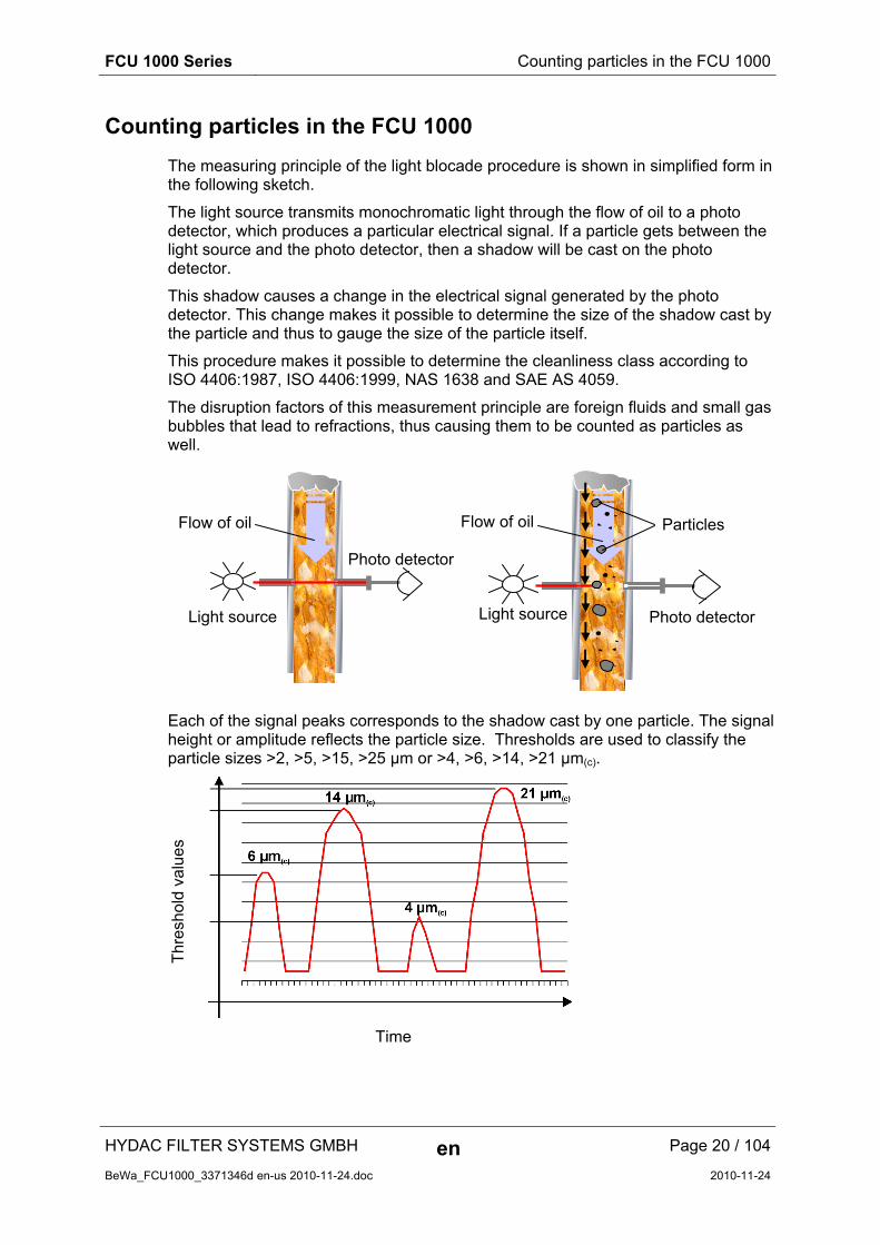
The measuring principle of the light blocade procedure is shown in simplified form in the following sketch.
The light source transmits monochromatic light through the flow of oil to a photo detector, which produces a particular electrical signal. If a particle gets between the light source and the photo detector, then a shadow will be cast on the photo detector.
This shadow causes a change in the electrical signal generated by the photo detector. This change makes it possible to determine the size of the shadow cast by the particle and thus to gauge the size of the particle itself.
This procedure makes it possible to determine the cleanliness class according to ISO 4406:1987, ISO 4406:1999, NAS 1638 and SAE AS 4059.
The disruption factors of this measurement principle are foreign fluids and small gas bubbles that lead to refractions, thus causing them to be counted as particles as well.
Each of the signal peaks corresponds to the shadow cast by one particle. The signal height or amplitude reflects the particle size. Thresholds are used to classify the particle sizes >2, >5, >15, >25 µm or >4, >6, >14, >21 µm(c).
Thr
esho
ld v
alue
s
Time
Flow of oil Flow of oil Particles
Photo detector Light source Light source
Photo detector
FCU 1000 Series How the FCU 1000 functions
HYDAC FILTER SYSTEMS GMBH en Page 21 / 104
BeWa_FCU1000_3371346d en-us 2010-11-24.doc 2010-11-24
How the FCU 1000 functions
INLET
1 2 3
4
6 7 8 9
5
OUTLET
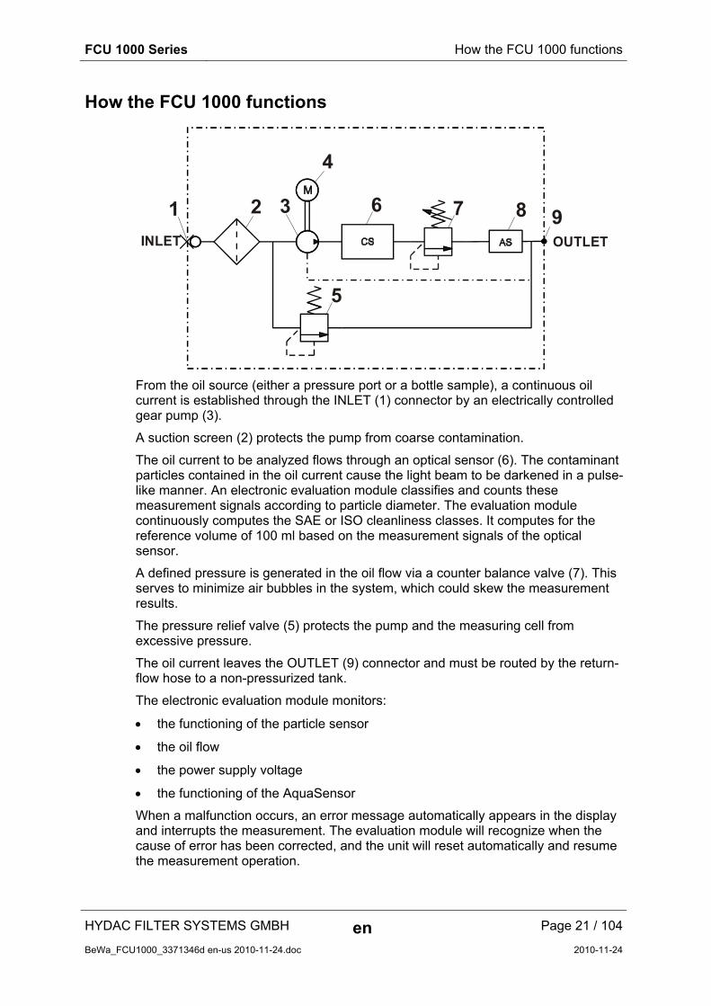
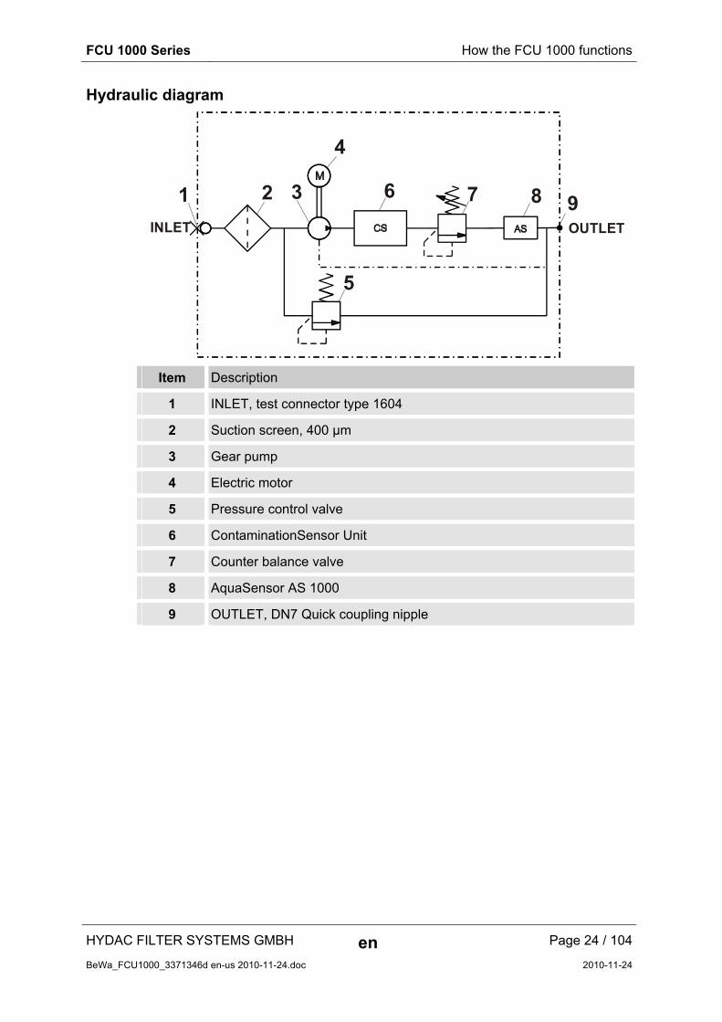
From the oil source (either a pressure port or a bottle sample), a continuous oil current is established through the INLET (1) connector by an electrically controlled gear pump (3).
A suction screen (2) protects the pump from coarse contamination.
The oil current to be analyzed flows through an optical sensor (6). The contaminant particles contained in the oil current cause the light beam to be darkened in a pulse-like manner. An electronic evaluation module classifies and counts these measurement signals according to particle diameter. The evaluation module continuously computes the SAE or ISO cleanliness classes. It computes for the reference volume of 100 ml based on the measurement signals of the optical sensor.
A defined pressure is generated in the oil flow via a counter balance valve (7). This serves to minimize air bubbles in the system, which could skew the measurement results.
The pressure relief valve (5) protects the pump and the measuring cell from excessive pressure.
The oil current leaves the OUTLET (9) connector and must be routed by the return-flow hose to a non-pressurized tank.
The electronic evaluation module monitors:
the functioning of the particle sensor
the oil flow
the power supply voltage
the functioning of the AquaSensor
When a malfunction occurs, an error message automatically appears in the display and interrupts the measurement. The evaluation module will recognize when the cause of error has been corrected, and the unit will reset automatically and resume the measurement operation.
FCU 1000 Series How the FCU 1000 functions
HYDAC FILTER SYSTEMS GMBH en Page 22 / 104
BeWa_FCU1000_3371346d en-us 2010-11-24.doc 2010-11-24
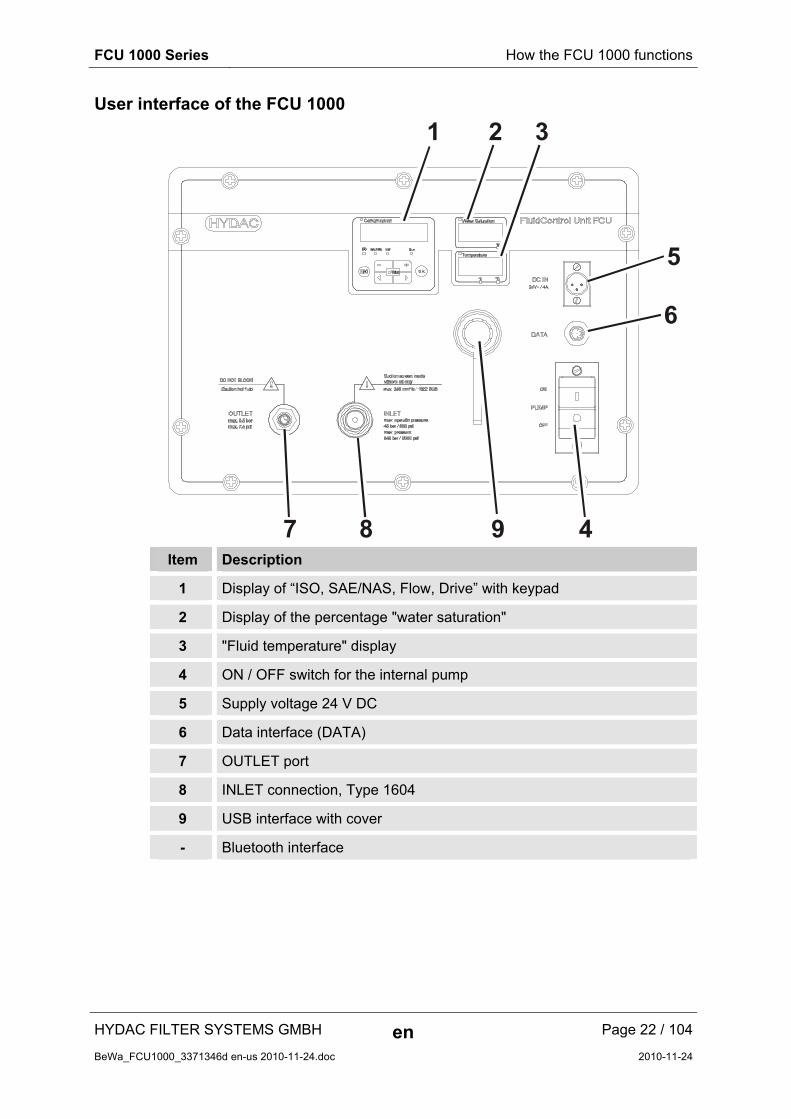
User interface of the FCU 1000
9
5
1 2 3
6
47 8
Item Description
1 Display of “ISO, SAE/NAS, Flow, Drive” with keypad
2 Display of the percentage "water saturation"
3 "Fluid temperature" display
4 ON / OFF switch for the internal pump
5 Supply voltage 24 V DC
6 Data interface (DATA)
7 OUTLET port
8 INLET connection, Type 1604
9 USB interface with cover
- Bluetooth interface
FCU 1000 Series How the FCU 1000 functions
HYDAC FILTER SYSTEMS GMBH en Page 23 / 104
BeWa_FCU1000_3371346d en-us 2010-11-24.doc 2010-11-24
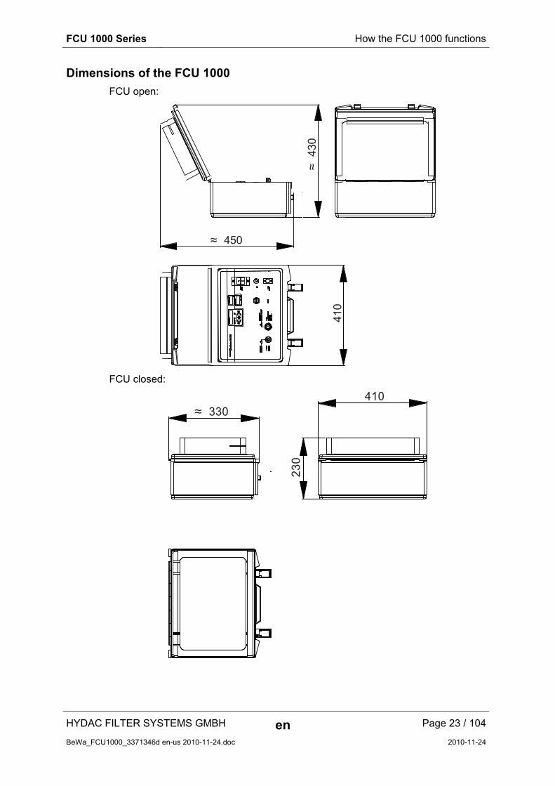
Dimensions of the FCU 1000
FCU open:
≈ 450
≈ 4
30
410
FCU closed:
≈ 330410
23
0
FCU 1000 Series How the FCU 1000 functions
HYDAC FILTER SYSTEMS GMBH en Page 24 / 104
BeWa_FCU1000_3371346d en-us 2010-11-24.doc 2010-11-24
Hydraulic diagram
INLET
1 2 3
4
6 7 8 9
5
OUTLET
Item Description
1 INLET, test connector type 1604
2 Suction screen, 400 µm
3 Gear pump
4 Electric motor
5 Pressure control valve
6 ContaminationSensor Unit
7 Counter balance valve
8 AquaSensor AS 1000
9 OUTLET, DN7 Quick coupling nipple
FCU 1000 Series Using the BatteryPack (accessory)
HYDAC FILTER SYSTEMS GMBH en Page 25 / 104
BeWa_FCU1000_3371346d en-us 2010-11-24.doc 2010-11-24
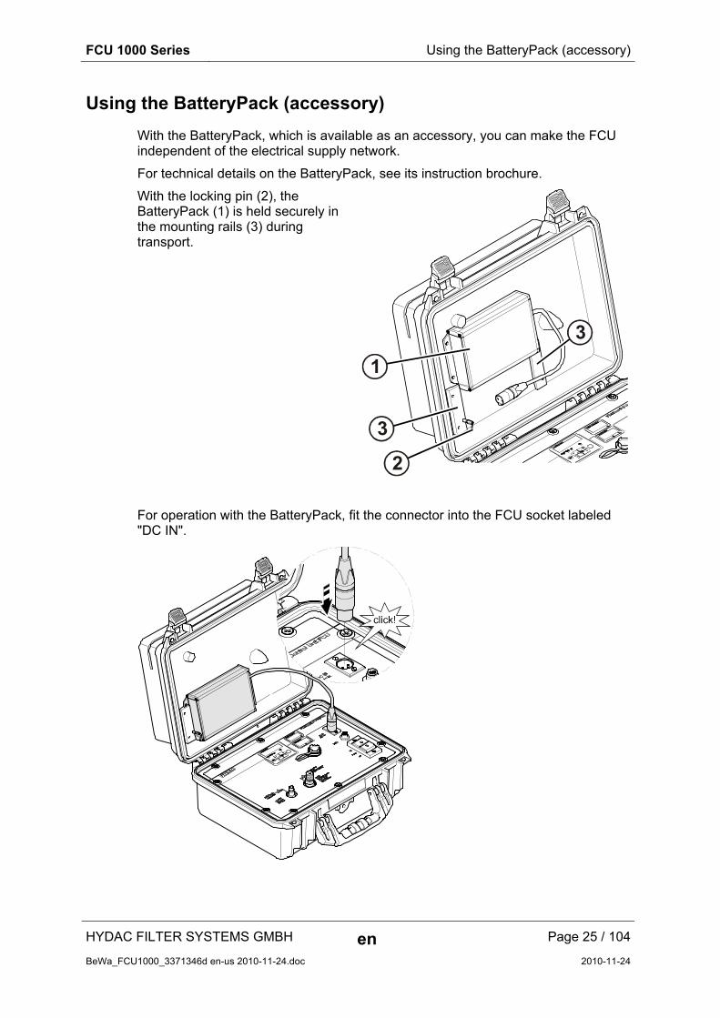
Using the BatteryPack (accessory)
With the BatteryPack, which is available as an accessory, you can make the FCU independent of the electrical supply network.
For technical details on the BatteryPack, see its instruction brochure.
With the locking pin (2), the BatteryPack (1) is held securely in the mounting rails (3) during transport.
1
3
3
2
For operation with the BatteryPack, fit the connector into the FCU socket labeled "DC IN".

FCU 1000 Series Using the BatteryPack (accessory)
HYDAC FILTER SYSTEMS GMBH en Page 26 / 104
BeWa_FCU1000_3371346d en-us 2010-11-24.doc 2010-11-24
To fit the BatteryPack into its holder, proceed as follows:
1. Remove the connector (A) from the socket on the BatteryPack.
A
2. Slide the BatteryPack into the mounting rails from above.
3. Pull the locking pin (1)
Slide the BatteryPack down until it touches the lower stop in the guide rails (2)
Release the locking pin (3). A spring will return the locking pin to its original position, thus securing the BatteryPack.
Check that the BatteryPack is firmly seated.
4. Insert the connector into the socket on the BatteryPack.

FCU 1000 Series Using the BatteryPack (accessory)
HYDAC FILTER SYSTEMS GMBH en Page 27 / 104
BeWa_FCU1000_3371346d en-us 2010-11-24.doc 2010-11-24
To remove it, proceed as follows:
1. Remove the connector from the socket.
2. Pull the locking pin out to release the BatteryPack (1).
Slide the BatteryPack upwards (2).
3. Pull the BatteryPack up and out of the mounting rails.
Then insert the connector back into the socket on the BatteryPack.
FCU 1000 Series Preparing the FCU for measurement
HYDAC FILTER SYSTEMS GMBH en Page 28 / 104
BeWa_FCU1000_3371346d en-us 2010-11-24.doc 2010-11-24
Preparing the FCU for measurement
Before operation, the FCU must first be hydraulically and electrically connected, as described below.
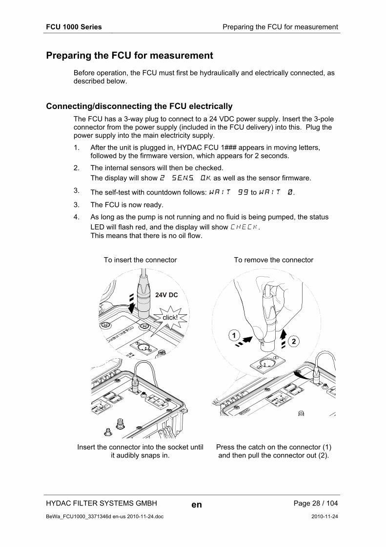
Connecting/disconnecting the FCU electrically
The FCU has a 3-way plug to connect to a 24 VDC power supply. Insert the 3-pole connector from the power supply (included in the FCU delivery) into this. Plug the power supply into the main electricity supply.
1. After the unit is plugged in, HYDAC FCU 1### appears in moving letters, followed by the firmware version, which appears for 2 seconds.
2. The internal sensors will then be checked.
The display will show 2 Sens ok as well as the sensor firmware.
3. The self-test with countdown follows: WAIT 99 to WAIT 0.
3. The FCU is now ready.
4. As long as the pump is not running and no fluid is being pumped, the status
LED will flash red, and the display will show CHECK. This means that there is no oil flow.
To insert the connector To remove the connector
24V DC
Insert the connector into the socket until it audibly snaps in.
Press the catch on the connector (1) and then pull the connector out (2).

FCU 1000 Series Preparing the FCU for measurement
HYDAC FILTER SYSTEMS GMBH en Page 29 / 104
BeWa_FCU1000_3371346d en-us 2010-11-24.doc 2010-11-24
Connecting/disconnecting the OUTLET hose
NOTICE
If the OUTLET connection is closed or blocked
The FCU will be damaged.
► Never seal the OUTLET connection.
► Put the free end of the OUTLET return hose into an unpressurized container.
max. 0.5 barmax. 7.5 psi
Plug in return hose Take off return hose
Fit the quick-action coupling on the OUTLET return hose to the nipple. Make sure that the coupling audibly snaps into place. Make sure that the quick-action coupling is firmly seated.
Put the other end of the OUTLET return hose into an unpressurized container.

FCU 1000 Series Preparing the FCU for measurement
HYDAC FILTER SYSTEMS GMBH en Page 30 / 104
BeWa_FCU1000_3371346d en-us 2010-11-24.doc 2010-11-24
Selecting the measurement point
Select the measurement location so that the sample measured comes from a turbulent location, with a good flow. For example on a pipe bend. This ensures that a typical sample is analyzed.
If the FCU is installed in near the measurement point, avoid delayed measurement results and sedimentation (particle deposits in the line).
While installing the INLET hose, make sure that no siphon results.
FCU 1000 Series Preparing the FCU for measurement
HYDAC FILTER SYSTEMS GMBH en Page 31 / 104
BeWa_FCU1000_3371346d en-us 2010-11-24.doc 2010-11-24
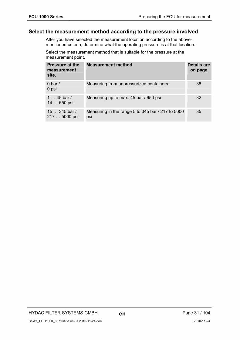
Select the measurement method according to the pressure involved
After you have selected the measurement location according to the above-mentioned criteria, determine what the operating pressure is at that location.
Select the measurement method that is suitable for the pressure at the measurement point.
Pressure at the measurement site.
Measurement method Details are on page
0 bar / 0 psi
Measuring from unpressurized containers 38
1 … 45 bar / 14 … 650 psi
Measuring up to max. 45 bar / 650 psi 32
15 … 345 bar / 217 … 5000 psi
Measuring in the range 5 to 345 bar / 217 to 5000 psi
35
FCU 1000 Series Measuring up to max. 45 bar / 650 psi
HYDAC FILTER SYSTEMS GMBH en Page 32 / 104
BeWa_FCU1000_3371346d en-us 2010-11-24.doc 2010-11-24
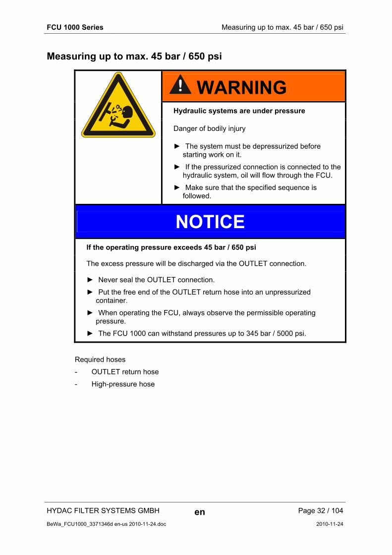
Measuring up to max. 45 bar / 650 psi
WARNING Hydraulic systems are under pressure
Danger of bodily injury
► The system must be depressurized before starting work on it.
► If the pressurized connection is connected to the hydraulic system, oil will flow through the FCU.
► Make sure that the specified sequence is followed.
NOTICE
If the operating pressure exceeds 45 bar / 650 psi
The excess pressure will be discharged via the OUTLET connection.
► Never seal the OUTLET connection.
► Put the free end of the OUTLET return hose into an unpressurized container.
► When operating the FCU, always observe the permissible operating pressure.
► The FCU 1000 can withstand pressures up to 345 bar / 5000 psi.
Required hoses
- OUTLET return hose
- High-pressure hose
FCU 1000 Series Measuring up to max. 45 bar / 650 psi
HYDAC FILTER SYSTEMS GMBH en Page 33 / 104
BeWa_FCU1000_3371346d en-us 2010-11-24.doc 2010-11-24
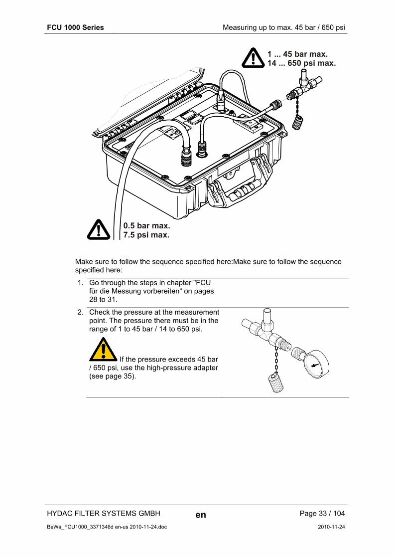
1 ... 45 bar max.14 ... 650 psi max.
0.5 bar max.7.5 psi max.
Make sure to follow the sequence specified here:Make sure to follow the sequence specified here:
1. Go through the steps in chapter "FCU für die Messung vorbereiten“ on pages 28 to 31.
2. Check the pressure at the measurement point. The pressure there must be in the range of 1 to 45 bar / 14 to 650 psi.
If the pressure exceeds 45 bar / 650 psi, use the high-pressure adapter (see page 35).

FCU 1000 Series Measuring up to max. 45 bar / 650 psi
HYDAC FILTER SYSTEMS GMBH en Page 34 / 104
BeWa_FCU1000_3371346d en-us 2010-11-24.doc 2010-11-24
3. Connect the INLET pressure hose (black) to the INLET port (1) of the FCU.
Screw the measurement coupling clockwise (2) onto the connection and screw it finger tight.
1
2
4. Switch on the internal pump.
5. Conclude by connecting the other end of the INLET pressure hose to the measurement port of the system.
1...45 bar max.1...650 psi max.
INLET
6. The hydraulic installation of the FCU is now complete.
7. The FCU will start with the measurement.
FCU 1000 Series Measuring in the range 5 to 345 bar / 217 to 5000 psi
HYDAC FILTER SYSTEMS GMBH en Page 35 / 104
BeWa_FCU1000_3371346d en-us 2010-11-24.doc 2010-11-24
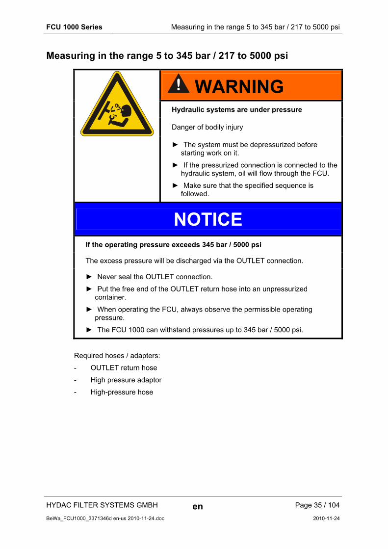
Measuring in the range 5 to 345 bar / 217 to 5000 psi
WARNING Hydraulic systems are under pressure
Danger of bodily injury
► The system must be depressurized before starting work on it.
► If the pressurized connection is connected to the hydraulic system, oil will flow through the FCU.
► Make sure that the specified sequence is followed.
NOTICE
If the operating pressure exceeds 345 bar / 5000 psi
The excess pressure will be discharged via the OUTLET connection.
► Never seal the OUTLET connection.
► Put the free end of the OUTLET return hose into an unpressurized container.
► When operating the FCU, always observe the permissible operating pressure.
► The FCU 1000 can withstand pressures up to 345 bar / 5000 psi.
Required hoses / adapters:
- OUTLET return hose
- High pressure adaptor
- High-pressure hose
FCU 1000 Series Measuring in the range 5 to 345 bar / 217 to 5000 psi
HYDAC FILTER SYSTEMS GMBH en Page 36 / 104
BeWa_FCU1000_3371346d en-us 2010-11-24.doc 2010-11-24
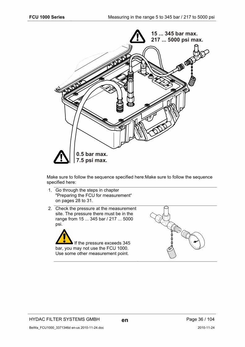
15 ... 345 bar max.217 ... 5000 psi max.
0.5 bar max.7.5 psi max.
Make sure to follow the sequence specified here:Make sure to follow the sequence specified here:
1. Go through the steps in chapter "Preparing the FCU for measurement“ on pages 28 to 31.
2. Check the pressure at the measurement site. The pressure there must be in the range from 15 ... 345 bar / 217 ... 5000 psi.
If the pressure exceeds 345 bar, you may not use the FCU 1000. Use some other measurement point.
FCU 1000 Series Measuring in the range 5 to 345 bar / 217 to 5000 psi
HYDAC FILTER SYSTEMS GMBH en Page 37 / 104
BeWa_FCU1000_3371346d en-us 2010-11-24.doc 2010-11-24
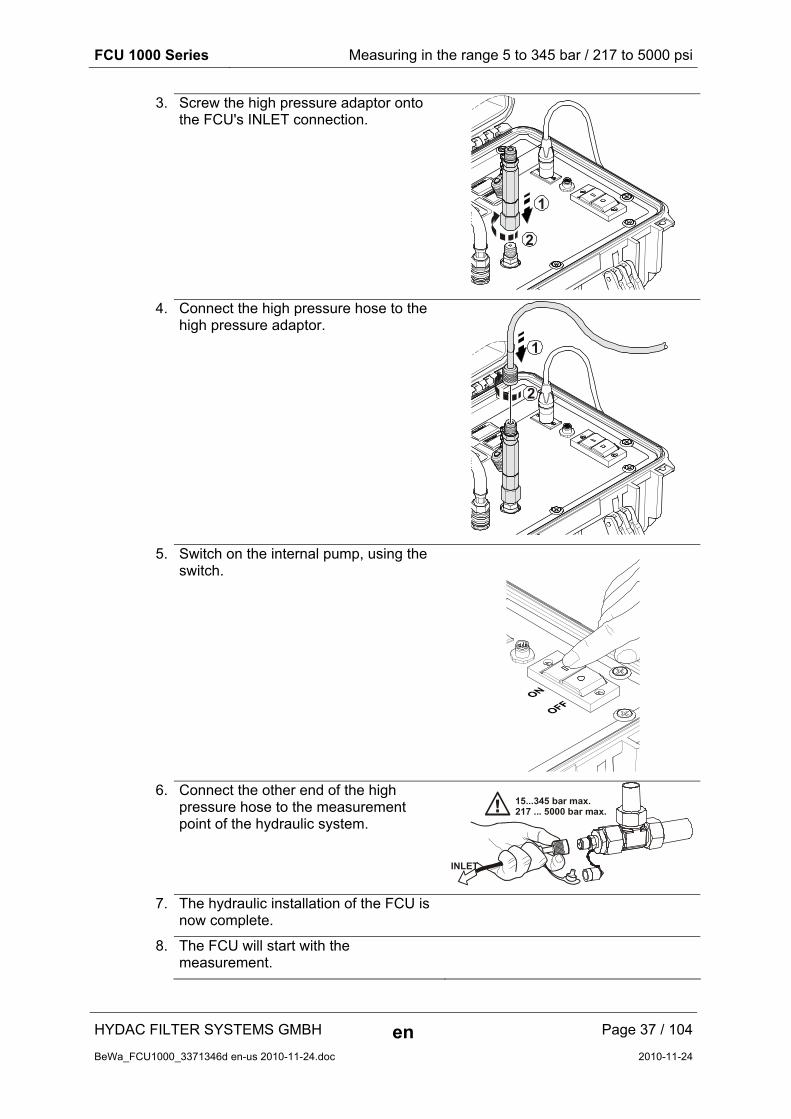
3. Screw the high pressure adaptor onto the FCU's INLET connection.
1
2
4. Connect the high pressure hose to the high pressure adaptor.
1
2
5. Switch on the internal pump, using the switch.
6. Connect the other end of the high pressure hose to the measurement point of the hydraulic system.
15...345 bar max.217 ... 5000 bar max.
INLET
7. The hydraulic installation of the FCU is now complete.
8. The FCU will start with the measurement.

FCU 1000 Series Measuring from unpressurized containers
HYDAC FILTER SYSTEMS GMBH en Page 38 / 104
BeWa_FCU1000_3371346d en-us 2010-11-24.doc 2010-11-24
Measuring from unpressurized containers
Required hoses
- OUTLET return hose
- Suction hose
max. 0.5 barmax. 7.5 psi
To guarantee valid and direct measurements, the FCU must be primed. To do this, you need approximately 120 ml of oil to completely fill the hydraulic circuit inside the FCU and INLET hose.
If the FCU is not primed, an air-oil mixture will flow through the FCU at the start of measurement. The sensor will interpret this air-oil mixture as particulate soiling and will thus falsify the measurement result.
For an initial test without priming the FCU and hoses, you need at least 300 ml of fluid.
FCU 1000 Series Measuring from unpressurized containers
HYDAC FILTER SYSTEMS GMBH en Page 39 / 104
BeWa_FCU1000_3371346d en-us 2010-11-24.doc 2010-11-24
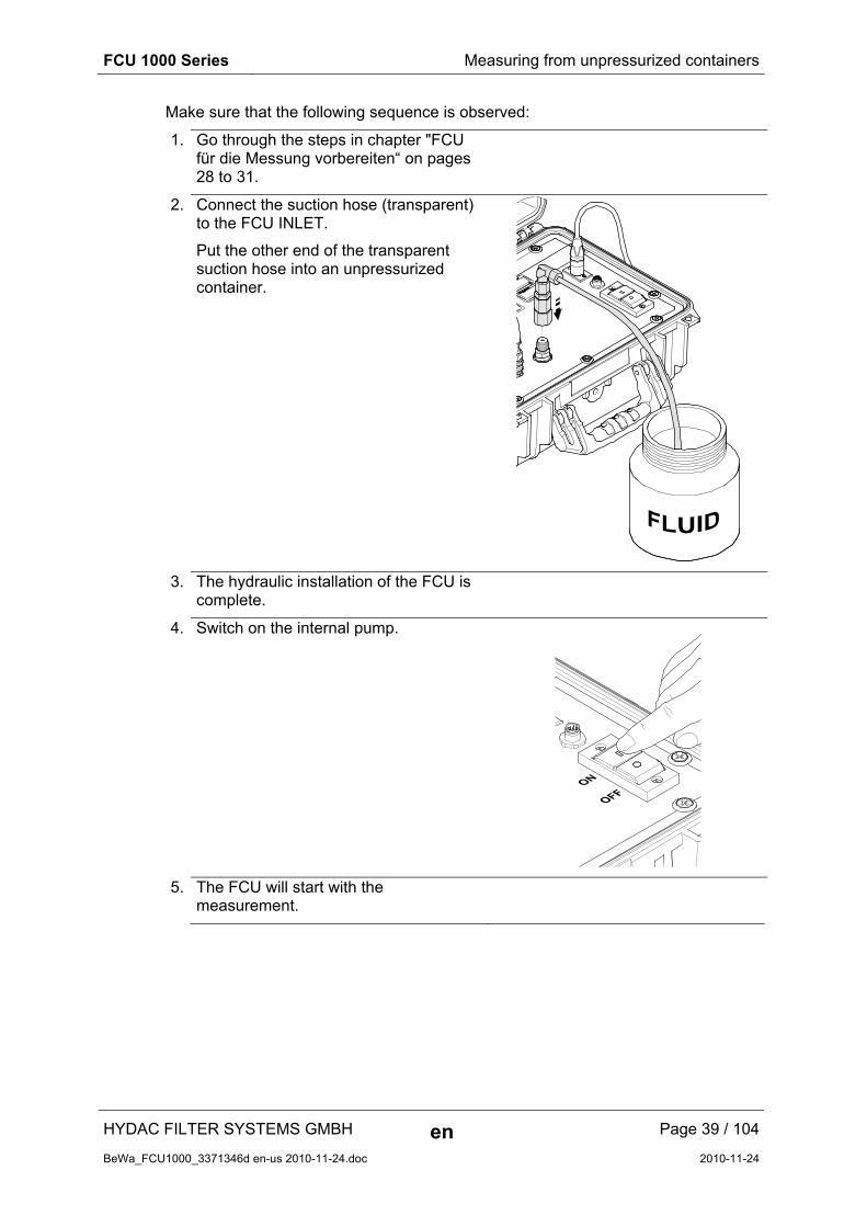
Make sure that the following sequence is observed:
1. Go through the steps in chapter "FCU für die Messung vorbereiten“ on pages 28 to 31.
2. Connect the suction hose (transparent) to the FCU INLET.
Put the other end of the transparent suction hose into an unpressurized container.
3. The hydraulic installation of the FCU is complete.
4. Switch on the internal pump.
5. The FCU will start with the measurement.
FCU 1000 Series Operating the FCU
HYDAC FILTER SYSTEMS GMBH en Page 40 / 104
BeWa_FCU1000_3371346d en-us 2010-11-24.doc 2010-11-24
Operating the FCU
If the FCU is powered up, then it can be used and parameters can be set.
In the following, the individual controls and their use are described.
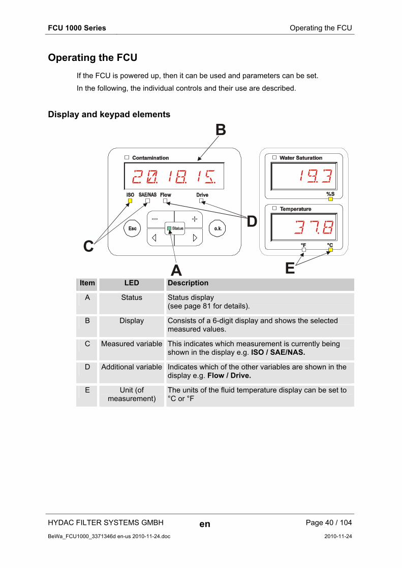
Display and keypad elements
2=1(1%
3/8
1)3
C
A
D
B
E Item LED Description
A Status Status display (see page 81 for details).
B Display Consists of a 6-digit display and shows the selected measured values.
C Measured variable This indicates which measurement is currently being shown in the display e.g. ISO / SAE/NAS.
D Additional variable Indicates which of the other variables are shown in the display e.g. Flow / Drive.
E Unit (of measurement)
The units of the fluid temperature display can be set to °C or °F
FCU 1000 Series Operating the FCU
HYDAC FILTER SYSTEMS GMBH en Page 41 / 104
BeWa_FCU1000_3371346d en-us 2010-11-24.doc 2010-11-24
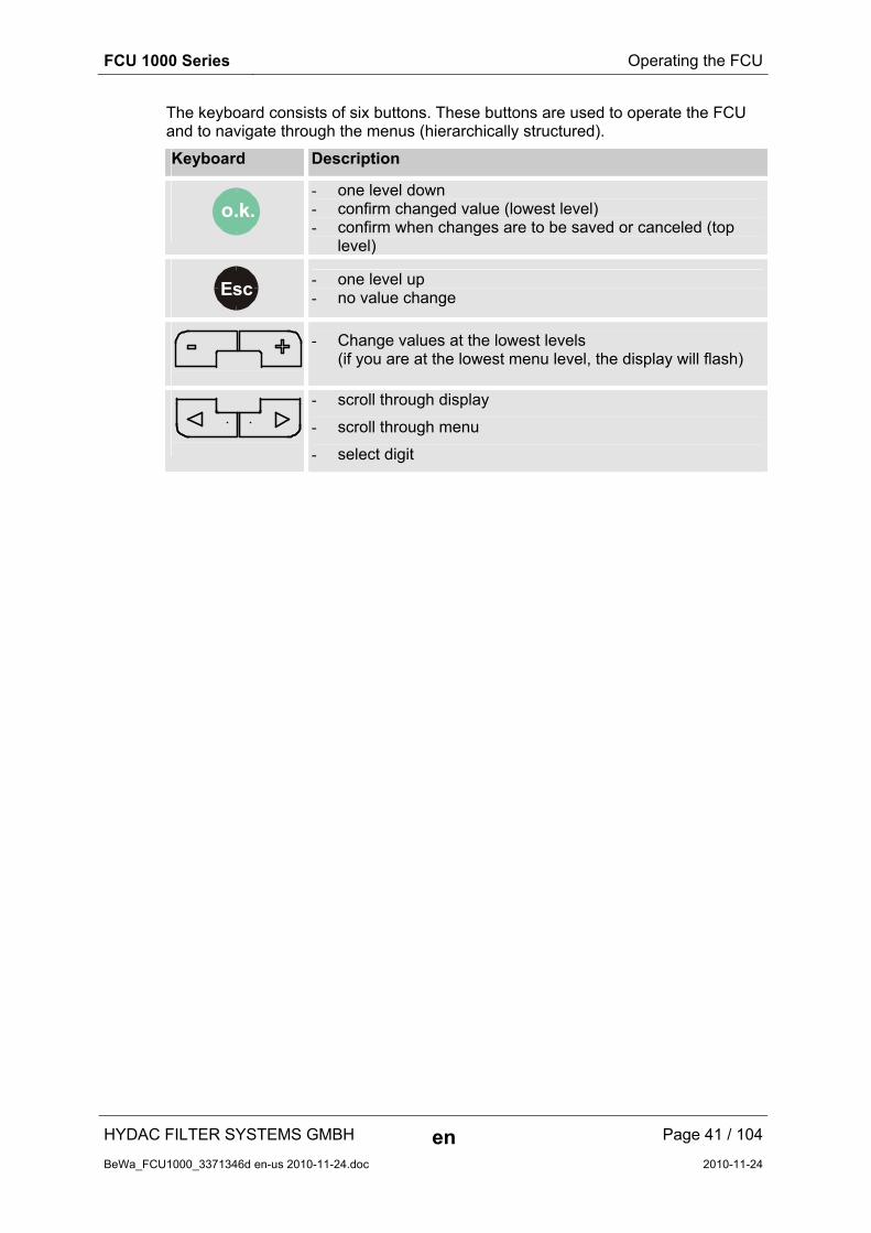
The keyboard consists of six buttons. These buttons are used to operate the FCU and to navigate through the menus (hierarchically structured).
Keyboard Description
o.k.
- one level down - confirm changed value (lowest level) - confirm when changes are to be saved or canceled (top
level)
Esc
- one level up - no value change
- Change values at the lowest levels (if you are at the lowest menu level, the display will flash)
- scroll through display
- scroll through menu
- select digit

FCU 1000 Series Clicking through the display
HYDAC FILTER SYSTEMS GMBH en Page 42 / 104
BeWa_FCU1000_3371346d en-us 2010-11-24.doc 2010-11-24
Clicking through the display
According to the calibration type (CALIB) in the power up menu, the following
displays can be clicked through with the buttons.
ISO.SAE display
Display Description
2=1(15ISO Flow DriveSAE/NAS
3-digit ISO code
1§4AISO Flow DriveSAE/NAS
SAE class A
1"6BISO Flow DriveSAE/NAS
SAE class B
1§0CISO Flow DriveSAE/NAS
SAE class C
1§1DISO Flow DriveSAE/NAS
SAE class D
MX1§4AISO Flow DriveSAE/NAS
SAE Max.
108ISO Flow DriveSAE/NAS
Flow rate in ml/min
42ISO Flow DriveSAE/NAS
LED current in %

FCU 1000 Series Clicking through the display
HYDAC FILTER SYSTEMS GMBH en Page 43 / 104
BeWa_FCU1000_3371346d en-us 2010-11-24.doc 2010-11-24
ISO.SAE display
Display Description
2$2"20ISO Flow DriveSAE/NAS
3-digit ISO code
ISO Flow DriveSAE/NAS
2-5 µm channel NAS
ISO Flow DriveSAE/NAS
5-15 µm channel NAS
ISO Flow DriveSAE/NAS
15-25 µm channel NAS
ISO Flow DriveSAE/NAS
> 25 µm channel NAS
ISO Flow DriveSAE/NAS
NAS Max.
108ISO Flow DriveSAE/NAS
Flow rate in ml/min
42ISO Flow DriveSAE/NAS
LED current in %
FCU 1000 Series Measured variables
HYDAC FILTER SYSTEMS GMBH en Page 44 / 104
BeWa_FCU1000_3371346d en-us 2010-11-24.doc 2010-11-24
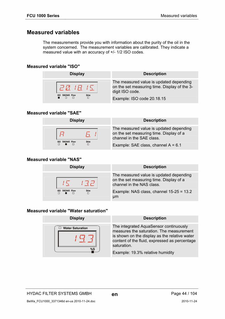
Measured variables
The measurements provide you with information about the purity of the oil in the system concerned. The measurement variables are calibrated. They indicate a measured value with an accuracy of +/- 1/2 ISO codes.
Measured variable "ISO"
Display Description
2=1(1%
The measured value is updated depending on the set measuring time. Display of the 3-digit ISO code.
Example: ISO code 20.18.15
Measured variable "SAE"
Display Description
A &1
The measured value is updated depending on the set measuring time. Display of a channel in the SAE class.
Example: SAE class, channel A = 6.1
Measured variable "NAS"
Display Description
15 1§2
The measured value is updated depending on the set measuring time. Display of a channel in the NAS class.
Example: NAS class, channel 15-25 = 13.2 µm
Measured variable "Water saturation"
Display Description
1)3
The integrated AquaSensor continuously measures the saturation. The measurement is shown on the display as the relative water content of the fluid, expressed as percentage saturation.
Example: 19.3% relative humidity

FCU 1000 Series Measured variables
HYDAC FILTER SYSTEMS GMBH en Page 45 / 104
BeWa_FCU1000_3371346d en-us 2010-11-24.doc 2010-11-24
Measured variable "Temperature"
Display Description
3/8
The integrated AquaSensor continuously measures the fluid temperature. The output as Celsius °C or Fahrenheit °F can be selected under TP.UNIT on page 55.
Example: Temperature = 37.8°C
Service variables
These values give you information about the determined flow and the light source power within the FCU. The service variables are not calibrated.
Service variables "Flow"
Display Description
120
Here, you can see the averaged flow through the contamination sensor unit.
Example: Flow rate = 120 ml/min
Service variables "Drive"
Display Description
60
Display of the light source efficiency (1-100%) with which the ContaminationSensor unit currently works.
Example: Light source efficiency = 60%

FCU 1000 Series FCU configuration menus
HYDAC FILTER SYSTEMS GMBH en Page 46 / 104
BeWa_FCU1000_3371346d en-us 2010-11-24.doc 2010-11-24
FCU configuration menus
The sensor has two operating levels with corresponding menus.
Menus Description Details are on page
Power Up Menu The basic settings for the FCU 46
Measuring Menu Settings for the recording and storing of the measurements and naming the measurement points.
51
Power Up Menu
In this menu, the basic settings for the operation of the FCU are made.
Selection To do
Start the power up menu. Press any button and hold it down while switching on the supply voltage
Exit the power up menu without saving.
Scroll to CANCEL and press o.k.
, or the option will be selected automatically after 30 seconds
Exit the power up menu after saving. Scroll to SAVE and press
o.k.
Power Up
Description For details, see page:
DAtTIM Set the system date 47
ADRESS Set bus address 47
DElMEM Delete the records 48
mTIME Set measuring time 48
CAlIb Select the calibration 49
DFAULT Reset to factory defaults 49
CANCEL Discard changes and exit 50
SAVE Save changes and exit 50
Press o.k.
to change to a sub-menu.

FCU 1000 Series FCU configuration menus
HYDAC FILTER SYSTEMS GMBH en Page 47 / 104
BeWa_FCU1000_3371346d en-us 2010-11-24.doc 2010-11-24
DAT.TIM – date / time
In this option you can set or alter the system date / time.
If the date has never been set, or if the battery is flat , the system date will be 2000-01-01 and the time will be 00:00.
The date format is YY.MM.DD => year / year / month / month / day / day.
The time uses 24 hour format HH.MM => hour / hour / minute / minute.
Use the following buttons to set the date and time:
To change digit
To change the value
o.k.To confirm the change
EscCancel and back
Contamination
SAE/NAS
0=000=0!01
Y
YY -> YearMM -> MonthDD -> Day
HH -> HourMM -> Minutes
HY. . .HM MM MDD
ADRESS - Bus address
With "ADRESS", you set the bus address to transmit the measurements over the data interface, using the HSI protocol.
There are 26 bus addresses available, from A - Z. Please note that each address may occur only once on any bus.
Use the following buttons to set the address:
To change digit
To change the value
o.k.To confirm the change
EscCancel and back
Contamination
SAE/NAS
A
The factory setting of the bus address is: A

FCU 1000 Series FCU configuration menus
HYDAC FILTER SYSTEMS GMBH en Page 48 / 104
BeWa_FCU1000_3371346d en-us 2010-11-24.doc 2010-11-24
DEL.MEM – Delete Memory
Here, you permanently delete all of the measurement records in the internal memory.
Before deletion, back up all of the measurement records on the USB memory stick.
Push the following buttons to:
o.k.Confirm deletion
EscCancel and back
Contamination
SAE/NAS
PUSH
OK
DELETE
M.TIME – Measurement Time
Here, you set the duration of the measurement. Select the duration in the range from 10 to 300 seconds. This value is factory set to 20 seconds.
Use the following buttons to set the duration of the measurement.
To change digit
To change the value
o.k.To confirm the change
EscCancel and back
Contamination
SAE/NAS
20
FCU 1000 Series FCU configuration menus
HYDAC FILTER SYSTEMS GMBH en Page 49 / 104
BeWa_FCU1000_3371346d en-us 2010-11-24.doc 2010-11-24
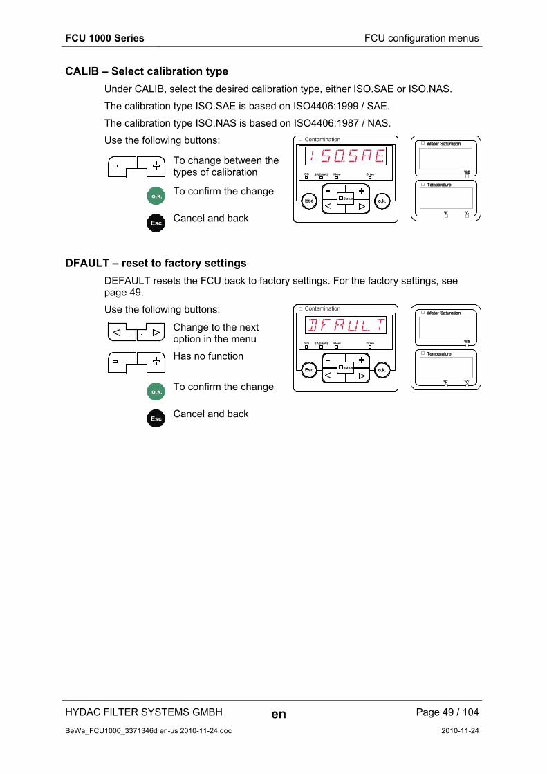
CALIB – Select calibration type
Under CALIB, select the desired calibration type, either ISO.SAE or ISO.NAS.
The calibration type ISO.SAE is based on ISO4406:1999 / SAE.
The calibration type ISO.NAS is based on ISO4406:1987 / NAS.
Use the following buttons:
To change between the types of calibration
o.k.To confirm the change
EscCancel and back
Contamination
SAE/NAS
ISoSAE
DFAULT – reset to factory settings
DEFAULT resets the FCU back to factory settings. For the factory settings, see page 49.
Use the following buttons:
Change to the next option in the menu
Has no function
o.k.To confirm the change
EscCancel and back
Contamination
SAE/NAS
DFAULT

FCU 1000 Series FCU configuration menus
HYDAC FILTER SYSTEMS GMBH en Page 50 / 104
BeWa_FCU1000_3371346d en-us 2010-11-24.doc 2010-11-24
CANCEL
CANCEL discards all changes and exits the popup menu.
Use the following buttons:
Change to the next option in the menu
o.k.Confirm
EscCancel and back
Contamination
SAE/NAS
CANCEL
SAVE – store data
SAVE stores all of your changes and exits the popup menu.
Use the following buttons:
Change to the next option in the menu
o.k.Confirm
EscCancel and back
Contamination
SAE/NAS
SAVE

FCU 1000 Series FCU configuration menus
HYDAC FILTER SYSTEMS GMBH en Page 51 / 104
BeWa_FCU1000_3371346d en-us 2010-11-24.doc 2010-11-24
Measuring Menu
The measuring menu allows you to change settings during operation.
Selection To do
Start the measuring menu Press the o.k.
button
Exit the measuring menu without saving
Scroll to CANCEL and press o.k.
or wait for 30 seconds with no further action and the FCU will automatically switch to display mode.
Save and exit the measuring menu Scroll to SAVE and press o.k.
Measuring Menu:
Description For details, see page
RECORD Record measurements 52
MEMORY Show free memory 53
EdMPNT Change measurement location name
54
TpUNIT Change temperature units 55
CANCEL Discard changes and exit 55
SAVE Save changes and exit 55
FCU 1000 Series FCU configuration menus
HYDAC FILTER SYSTEMS GMBH en Page 52 / 104
BeWa_FCU1000_3371346d en-us 2010-11-24.doc 2010-11-24
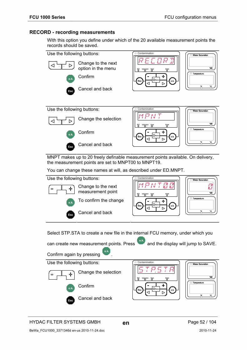
RECORD - recording measurements
With this option you define under which of the 20 available measurement points the records should be saved.
Use the following buttons:
Change to the next option in the menu
o.k.Confirm
EscCancel and back
Contamination
SAE/NAS
RECORD
Use the following buttons:
Change the selection
o.k.Confirm
EscCancel and back
Contamination
SAE/NAS
MPNT
MNPT makes up to 20 freely definable measurement points available. On delivery, the measurement points are set to MNPT00 to MNPT19.
You can change these names at will, as described under ED.MNPT.
Use the following buttons:
Change to the next measurement point
o.k.To confirm the change
EscCancel and back
Contamination
SAE/NAS
MPNT00 0
Select STP.STA to create a new file in the internal FCU memory, under which you
can create new measurement points. Press o.k.
and the display will jump to SAVE.
Confirm again by pressing o.k.
.
Use the following buttons:
Change the selection
o.k.Confirm
EscCancel and back
Contamination
SAE/NAS
STpSTA

FCU 1000 Series FCU configuration menus
HYDAC FILTER SYSTEMS GMBH en Page 53 / 104
BeWa_FCU1000_3371346d en-us 2010-11-24.doc 2010-11-24
MEMORY – display free memory
Under MEMORY, you check the current free internal memory capacity of the FCU in %. If there is no more memory available, no measurement records can be saved.
Copy the measurement records that you have already read out as described on page 59Fehler! Textmarke nicht definiert.. Then delete those records in the internal memory with DEL.MEM as described on page 48.
For example: 97% free memory.
Use the following buttons:
o.k. To confirm the change
EscCancel and back
Contamination
SAE/NAS
MEMORY 97
FREE
FCU 1000 Series FCU configuration menus
HYDAC FILTER SYSTEMS GMBH en Page 54 / 104
BeWa_FCU1000_3371346d en-us 2010-11-24.doc 2010-11-24
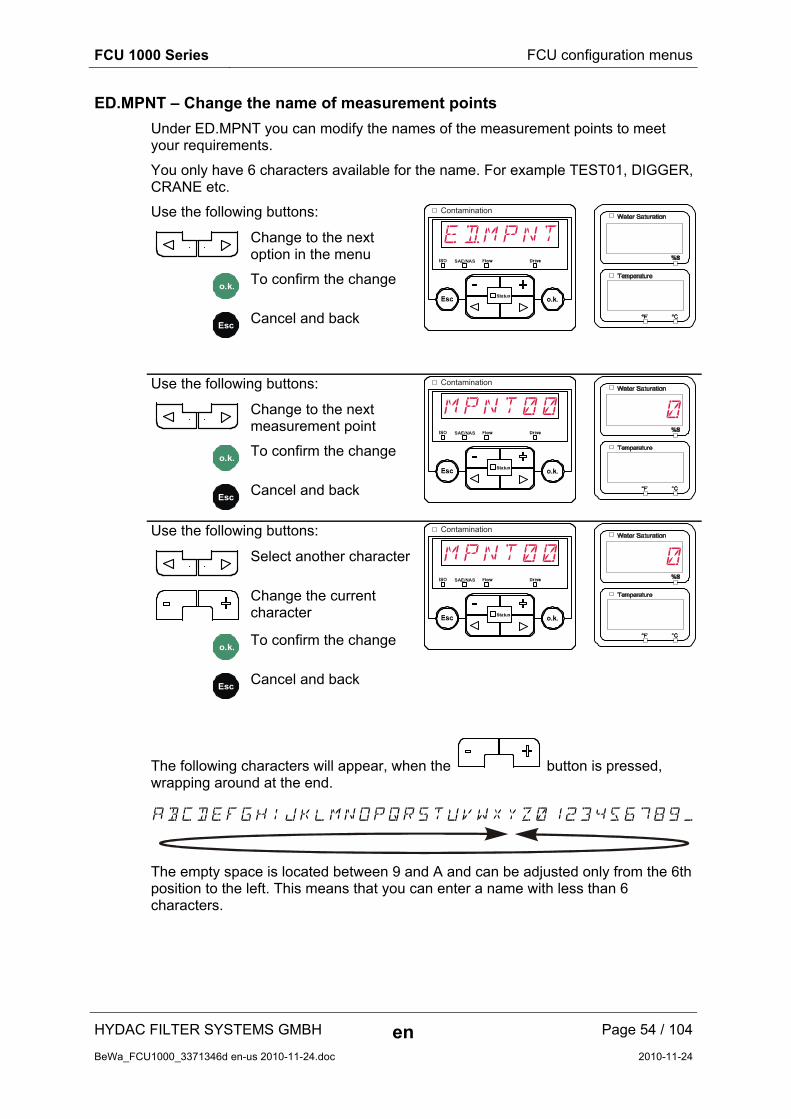
ED.MPNT – Change the name of measurement points
Under ED.MPNT you can modify the names of the measurement points to meet your requirements.
You only have 6 characters available for the name. For example TEST01, DIGGER, CRANE etc.
Use the following buttons:
Change to the next option in the menu
o.k.To confirm the change
EscCancel and back
Contamination
SAE/NAS
EdMPNT
Use the following buttons:
Change to the next measurement point
o.k.To confirm the change
EscCancel and back
Contamination
SAE/NAS
MPNT00 0
Use the following buttons:
Select another character
Change the current character
o.k.To confirm the change
EscCancel and back
Contamination
SAE/NAS
MPNT00 0
The following characters will appear, when the button is pressed, wrapping around at the end.
ABCDEFGHIJKLMNOPQRSTUVWXYZ0123456789_
The empty space is located between 9 and A and can be adjusted only from the 6th position to the left. This means that you can enter a name with less than 6 characters.

FCU 1000 Series FCU configuration menus
HYDAC FILTER SYSTEMS GMBH en Page 55 / 104
BeWa_FCU1000_3371346d en-us 2010-11-24.doc 2010-11-24
TP.UNIT – change the temperature units °C / °F
Under TP.UNIT you set the units to display the fluid temperature. You have the choice between Celsius °C and Fahrenheit °F.
Use the following buttons:
Change to the next option in the menu
o.k.Confirm
EscCancel and back
Contamination
SAE/NAS
TpUNIT
Use the following buttons:
Change the selection
o.k.Confirm
EscCancel and back
Contamination
SAE/NAS
DEG C
CANCEL
With CANCEL, you discard all changes and exit the measuring menu.
Use the following buttons:
Change to the next option in the menu
o.k.Confirm
EscCancel and back
Contamination
SAE/NAS
CANCEL
SAVE - save data
With SAVE, you store all changes and exit the measuring menu.
Use the following buttons:
Change to the next option in the menu
o.k.Confirm
EscCancel and back
Contamination
SAE/NAS
SAVE

FCU 1000 Series Performing a measurement
HYDAC FILTER SYSTEMS GMBH en Page 56 / 104
BeWa_FCU1000_3371346d en-us 2010-11-24.doc 2010-11-24
Performing a measurement
1. Check all the hydraulic and electrical connections to the FCU.
2. Now press the green "Pump ON" switch.
3. The pump feeds oil to be analyzed through the FCU. After the set measurement duration, the result will be shown on the display, and the status LED will light up green, steadily.
Restrictions pertaining to use
NOTICE
Impermissible operating conditions
The FCU will be damaged
► Only use the FCU with mineral oils or mineral oil-based raffinates.
► Observe the permissible viscosity range: 10 – 350 mm²/s or 46 – 1622 SUS (ISO VG 68)
► Only operate the FCU 1000 for brief periods of time (S4 to DIN EN 60034 / VDE 0530).
► After 30 minutes of operation, turn off the FCU 1000 for at least 10 minutes to cool down.
Internal measurement memory
All measurements are kept in internal memory, with a reference to the measurement point, until deliberately deleted by using the DEL.MEM function.
The internal memory has a capacity of > 30000 lines = measurement records.
To hit the capacity limit of the internal memory, it is theoretically necessary, with a measurement interval of 20 seconds (factory set), to run the FCU for 7 days, 24 hours per day.
To transfer the data, the target system (e.g. PC or USB stick) has to have at least 10 MB of capacity free.

FCU 1000 Series DATA - interface
HYDAC FILTER SYSTEMS GMBH en Page 57 / 104
BeWa_FCU1000_3371346d en-us 2010-11-24.doc 2010-11-24
DATA - interface
The FCU has a DATA interface to transfer the measurement data. The FCU communicates over this using the HSI protocol.
Connecting the FCU with CSI-B-2 kit
The FCU 1000 can be connected to a PC using the CSI-B-2 kit.
RS 485
18…35 V DC
CustomerSystem
PC
ZBE 08S-02ZBE 08S-05
max. 10 m
5
FCU 1000
Bluetooth
DATA
X2
1
1
2
2
3
3
4
4
5
5678
RS485
CSI-B-2
RS232RS 232
RS
232
RS
23
2
US
B A
Pins used on the DATA interface (HYDAC Sensor Interface – HSI)
The HSI interface has connection plug M12x1, 5-pole, in accordance with DIN VDE 0627.
Pin Assignment
1 Not connected
2 Not connected
3 Not connected
4 GND
5 HSI

FCU 1000 Series DATA - interface
HYDAC FILTER SYSTEMS GMBH en Page 58 / 104
BeWa_FCU1000_3371346d en-us 2010-11-24.doc 2010-11-24
Connecting the FCU with HMG 510 / HMG 3000
The following portable data recorders (HMGs) can be used to give a readout of the FCU 1000 via the DATA interface.
HMG 510 (with firmware version 2, release 15 or higher)
HMG 3000 (with firmware version 2, release 1 or higher)
See the operating instructions for the HMG for further details.
FCU 1000 Series USB interface
HYDAC FILTER SYSTEMS GMBH en Page 59 / 104
BeWa_FCU1000_3371346d en-us 2010-11-24.doc 2010-11-24
USB interface
Copying measurements onto a USB data stick
Compatibility with other USB memory sticks cannot be guaranteed as the FCU communicates directly with the microprocessor. This means that communication errors can't be corrected in software, as on a PC with an operating system.
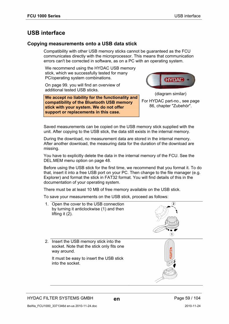
We recommend using the HYDAC USB memory stick, which we successfully tested for many PC/operating system combinations.
On page 99. you will find an overview of additional tested USB sticks.
We accept no liability for the functionality and compatibility of the Bluetooth USB memory stick with your system. We do not offer support or replacements in this case.
(diagram similar)
For HYDAC part-no., see page 86, chapter "Zubehör".
Saved measurements can be copied on the USB memory stick supplied with the unit. After copying to the USB stick, the data still exists in the internal memory.
During the download, no measurement data are stored in the internal memory. After another download, the measuring data for the duration of the download are missing.
You have to explicitly delete the data in the internal memory of the FCU. See the DEL.MEM menu option on page 48.
Before using the USB stick for the first time, we recommend that you format it. To do that, insert it into a free USB port on your PC. Then change to the file manager (e.g. Explorer) and format the stick in FAT32 format. You will find details of this in the documentation of your operating system.
There must be at least 10 MB of free memory available on the USB stick.
To save your measurements on the USB stick, proceed as follows:
1. Open the cover to the USB connection by turning it anticlockwise (1) and then lifting it (2).
2. Insert the USB memory stick into the socket. Note that the stick only fits one way around.
It must be easy to insert the USB stick into the socket.
FCU 1000 Series USB interface
HYDAC FILTER SYSTEMS GMBH en Page 60 / 104
BeWa_FCU1000_3371346d en-us 2010-11-24.doc 2010-11-24
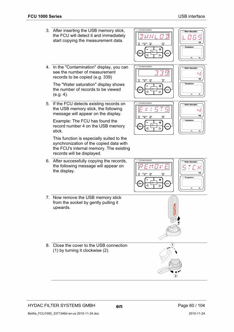
3. After inserting the USB memory stick, the FCU will detect it and immediately start copying the measurement data.
Contamination
SAE/NAS
LOGSDWNLOD
4. In the "Contamination" display, you can see the number of measurement records to be copied (e.g. 339)
The "Water saturation" display shows the number of records to be viewed (e.g. 4).
Contamination
SAE/NAS
4339
5. If the FCU detects existing records on the USB memory stick, the following message will appear on the display.
Example: The FCU has found the record number 4 on the USB memory stick.
This function is especially suited to the synchronization of the copied data with the FCU's internal memory. The existing records will be displayed.
Contamination
SAE/NAS
4EXISTS
6. After successfully copying the records, the following message will appear on the display.
Contamination
SAE/NAS
STCKREMOVE
7. Now remove the USB memory stick from the socket by gently pulling it upwards.
8. Close the cover to the USB connection (1) by turning it clockwise (2).

FCU 1000 Series USB interface
HYDAC FILTER SYSTEMS GMBH en Page 61 / 104
BeWa_FCU1000_3371346d en-us 2010-11-24.doc 2010-11-24
Data transmission failed - "ERROR COPY"
If a fault occurs during the copy procedure, or if you remove the USB memory stick from the socket before the procedure is complete, the following message will be output on the display.
Contamination
SAE/NAS
COPYERROR
To remedy faults, proceed as follows:
Ste
p
Description
1. Insert the USB memory stick in your PC and delete all data.
2. Put the USB stick back in the FCU USB socket. The download will start automatically.
->a. If the error recurs -> go to step 4. 3.
->b. If the error does not recur -> go to step 11.
4. Insert the USB stick in your PC and reformat it.
5. Put the USB stick back in the FCU USB socket. The download will start automatically.
->a. If the error recurs -> go to step 7. 6.
->b. If the error does not recur -> go to step 11.
7. Use another compatible USB memory stick (see page 99).
8. Put the USB stick back in the FCU USB socket. The download will start automatically.
->a. If the error recurs -> go to step 10. 9.
->b. If the error does not recur -> go to step 11.
10. Contact the HYDAC service department.
11. The download has been successfully completed

FCU 1000 Series Bluetooth interface
HYDAC FILTER SYSTEMS GMBH en Page 62 / 104
BeWa_FCU1000_3371346d en-us 2010-11-24.doc 2010-11-24
Bluetooth interface
The FCU 1000 Bluetooth interface is based on Bluetooth Version 1.2, Class 3. This means that:
Bluetooth Version 1.2: is less sensitive to static disturbances (e.g. WLAN), the maximum data transfer rate is 732.2 kBit/s
Class 3: a maximum performance of 1mW or 0 dBm, reaches a maximum of 10 m outdoors. This distance is strongly influenced by disturbances and obstacles in its vicinity.
Bluetooth
10 m
3 m
FCU 1000 Series Bluetooth interface
HYDAC FILTER SYSTEMS GMBH en Page 63 / 104
BeWa_FCU1000_3371346d en-us 2010-11-24.doc 2010-11-24
Installing the Bluetooth USB adaptor
If the PC already has a Bluetooth interface, use only this to establish a connection to the FCU.
Prior to the installation of new Bluetooth software, we strongly recommend deinstalling all existing Bluetooth drivers. The parallel use of different Bluetooth interfaces leads to diver conflicts.
If problems should arise, consult the Bluetooth USB adaptor handbook or consult the manufacturer of your PC hardware.
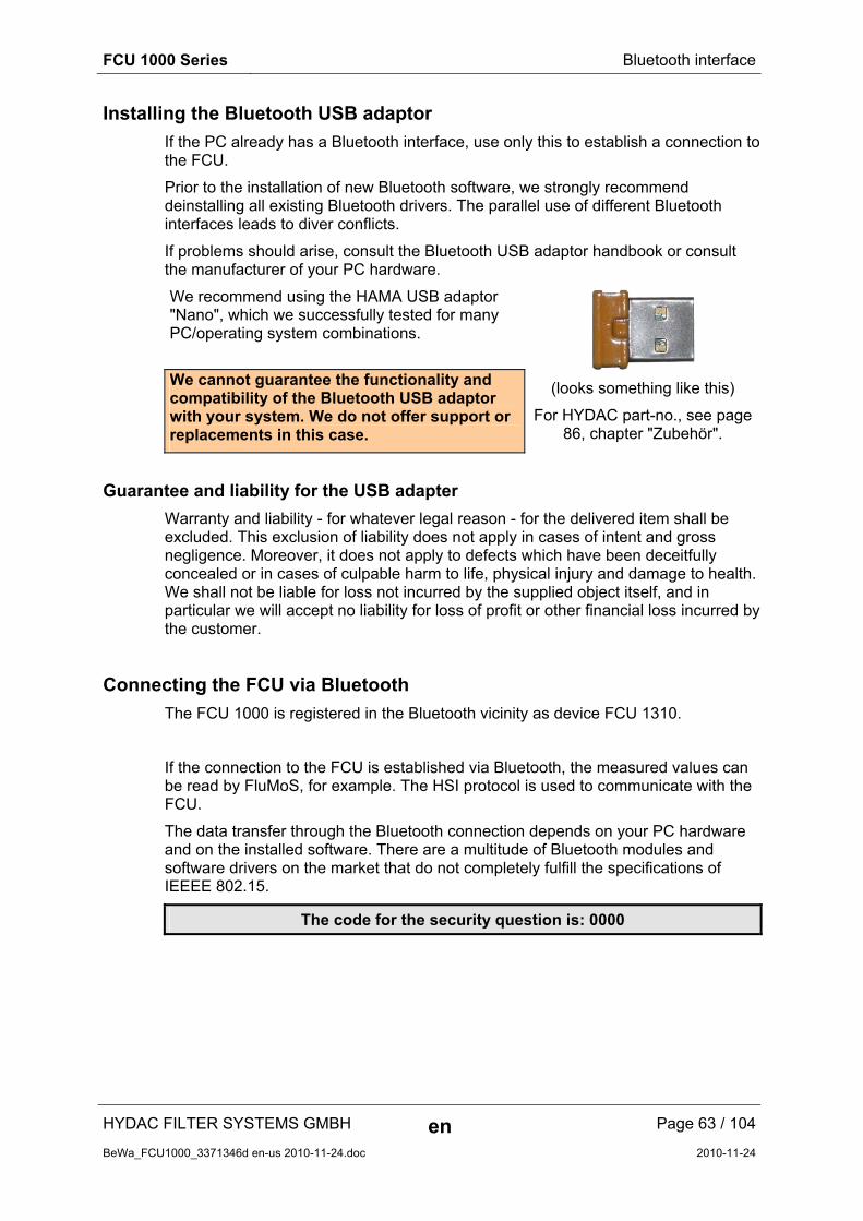
We recommend using the HAMA USB adaptor "Nano", which we successfully tested for many PC/operating system combinations.
We cannot guarantee the functionality and compatibility of the Bluetooth USB adaptor with your system. We do not offer support or replacements in this case.
(looks something like this)
For HYDAC part-no., see page 86, chapter "Zubehör".
Guarantee and liability for the USB adapter
Warranty and liability - for whatever legal reason - for the delivered item shall be excluded. This exclusion of liability does not apply in cases of intent and gross negligence. Moreover, it does not apply to defects which have been deceitfully concealed or in cases of culpable harm to life, physical injury and damage to health. We shall not be liable for loss not incurred by the supplied object itself, and in particular we will accept no liability for loss of profit or other financial loss incurred by the customer.
Connecting the FCU via Bluetooth
The FCU 1000 is registered in the Bluetooth vicinity as device FCU 1310.
If the connection to the FCU is established via Bluetooth, the measured values can be read by FluMoS, for example. The HSI protocol is used to communicate with the FCU.
The data transfer through the Bluetooth connection depends on your PC hardware and on the installed software. There are a multitude of Bluetooth modules and software drivers on the market that do not completely fulfill the specifications of IEEEE 802.15.
The code for the security question is: 0000

FCU 1000 Series Evaluating stored records
HYDAC FILTER SYSTEMS GMBH en Page 64 / 104
BeWa_FCU1000_3371346d en-us 2010-11-24.doc 2010-11-24
Evaluating stored records
The measurement records read out of the FCU and stored on the USB memory stick are defined as follows.
Directories to store the records by measurement points
If measurements are to be stored under a measurement point MNPT, the FCU will automatically produce a directory for this measurement point and will put the record there.
Record file names
The file names of the measurement records consist of date YY -> year, MM -> month, DD -> day, as well as a incremental number.
09 _ 02 _ 05 . 026
YY _ MM _ DD . incremental number
A new record is created:
- on request by STA.STP
- after a restart of the FCU (see page 84)
- after the data is downloaded to the USB stick
For each new record, the incremental number is increased by one.
FCU 1000 Series Evaluating stored records
HYDAC FILTER SYSTEMS GMBH en Page 65 / 104
BeWa_FCU1000_3371346d en-us 2010-11-24.doc 2010-11-24
Evaluating the file containing the measurements
The file containing the measurements has a file extension, for example "026". This extension may not be recognized by your PC. This means that you must tell your PC that, in future, you would like to open this file with MS Excel.
Open the file with MS excel by right-clicking on it and then selecting "Open". A window will open where you will be asked to choose which program should open the file.
In principle, you can do this for every extension from "000" to "999".
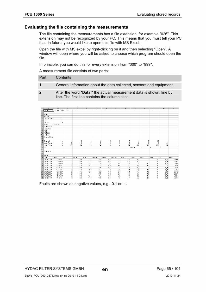
A measurement file consists of two parts:
Part Contents
1 General information about the data collected, sensors and equipment.
2 After the word *Data,* the actual measurement data is shown, line by line. The first line contains the column titles.
Faults are shown as negative values, e.g. -0.1 or -1.
FCU 1000 Series Evaluating stored records
HYDAC FILTER SYSTEMS GMBH en Page 66 / 104
BeWa_FCU1000_3371346d en-us 2010-11-24.doc 2010-11-24
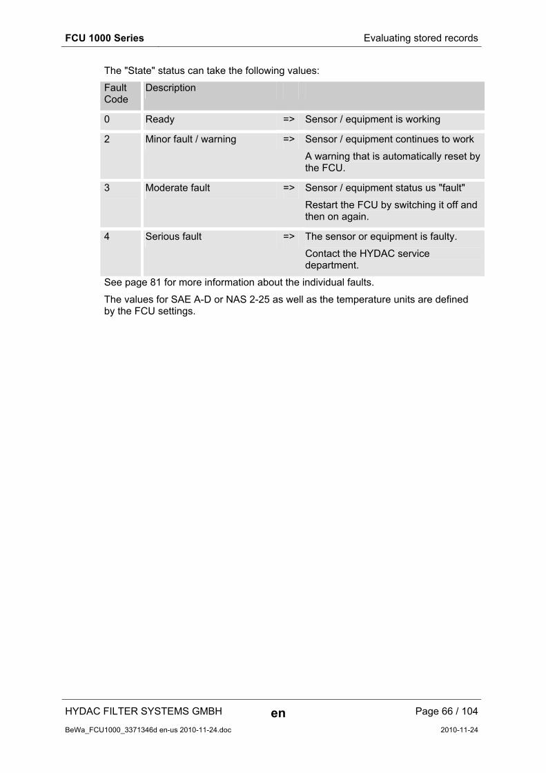
The "State" status can take the following values:
Fault Code
Description
0 Ready => Sensor / equipment is working
2 Minor fault / warning => Sensor / equipment continues to work
A warning that is automatically reset by the FCU.
3 Moderate fault => Sensor / equipment status us "fault"
Restart the FCU by switching it off and then on again.
4 Serious fault => The sensor or equipment is faulty.
Contact the HYDAC service department.
See page 81 for more information about the individual faults.
The values for SAE A-D or NAS 2-25 as well as the temperature units are defined by the FCU settings.

FCU 1000 Series Evaluating stored records
HYDAC FILTER SYSTEMS GMBH en Page 67 / 104
BeWa_FCU1000_3371346d en-us 2010-11-24.doc 2010-11-24
The measurements are shown as dates
On opening the file, all decimal numbers will be shown as dates. To resolve this, proceed as follows:
1. Start Excel.
2. From the menu bar, select the "Open" command.
Open the measurement file.
3. The
text conversion assistant will open - step 1 of 3.
Check the settings
Press the "Continue" button to accept the settings.
4. Text conversion assistant step 2 of 3
Check the settings
Press the "Continue" button to accept the settings.
5. Text conversion assistant - step 3 of 3
Press the "Continue" button.
6. Change the following settings
Set the decimal separator to be a dot and the 1000s separator to be a comma.
Confirm the changes with the OK button.
Separated
Fixed width
Continue > Finish Abort < Back
Original data type
Select the data type that best describes your data:
Import starts in line: Source of file:
Text conversion assistant - step 1 of 3
Tab stop
Preview of the marked data
Continue > Finish Abort < Back
Treat adjacent delimiters as a character
Delimiter
Text recognition character:
Text conversion assistant - step 2 of 3
Space
Semicolon
Other:
Comma
Preview of the marked data
Continue > Finish Abort < Back
Data format of the columns
Text conversion assistant - step 3 of 3
Other
Standard
Text
Do not import columns
Date
Decimal separator:
Other text import settings
1000s separator:
OK Abort Reset
Delimiter used for numeric data:

FCU 1000 Series Measurement value readouts with FluMoS
HYDAC FILTER SYSTEMS GMBH en Page 68 / 104
BeWa_FCU1000_3371346d en-us 2010-11-24.doc 2010-11-24
7. Click on the "Finish" button, to complete the import of the measurement data.
8. Decimal numbers are now displayed correctly.
Measurement value readouts with FluMoS
The fluid monitoring software FluMoS serves to read the measurements from the FCU 1000. From version 1.30 of FluMos Light, it is possible to display and evaluate the data on the USB memory stick.
FluMoS light is available as freeware on the CD included in the delivery or as a download.
You will find the link for the download on our homepage at www.hydac.com
Preview of the marked data
Continue > Finish Abort < Back
Data format of the columns
Text conversion assistant - step 3 of 3
Other
Standard
Text
Do not import column
Date

FCU 1000 Series Preparing the FCU for transport
HYDAC FILTER SYSTEMS GMBH en Page 69 / 104
BeWa_FCU1000_3371346d en-us 2010-11-24.doc 2010-11-24
Preparing the FCU for transport
CAUTION
Hot fluid at the OUTLET
Danger of burns
► Before removing the OUTLET hose from the FCU, allow it to cool off.
To prepare the FCU for transport, observe the following sequence:
1. Use the switch to turn the internal pump off.
2. Remove the USB stick, should it be inserted.
3. Close the USB socket with the corresponding cover.
4. First undo the end of the high-pressure INLET hose that is at the measurement point of the hydraulic system.
INLET

FCU 1000 Series Preparing the FCU for transport
HYDAC FILTER SYSTEMS GMBH en Page 70 / 104
BeWa_FCU1000_3371346d en-us 2010-11-24.doc 2010-11-24
5. Remove the hose by turning the connector to the FCU INLET connection anticlockwise.
1
2
1
2
4
3
2
1
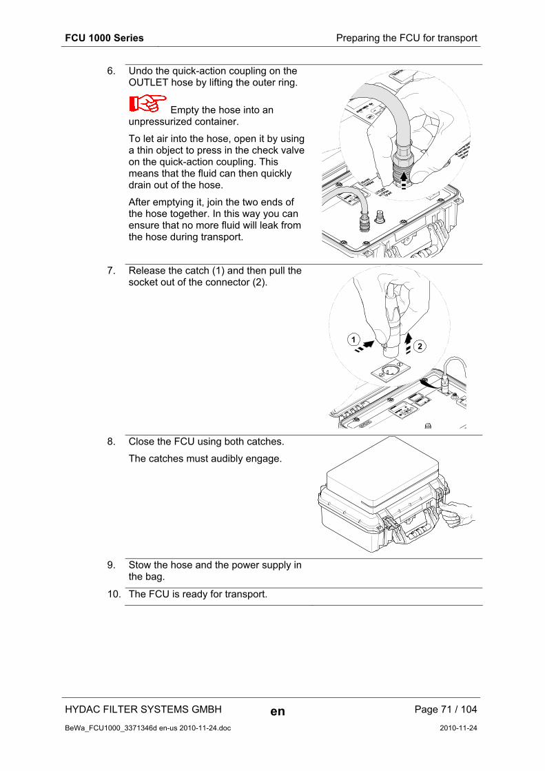
FCU 1000 Series Preparing the FCU for transport
HYDAC FILTER SYSTEMS GMBH en Page 71 / 104
BeWa_FCU1000_3371346d en-us 2010-11-24.doc 2010-11-24
6. Undo the quick-action coupling on the OUTLET hose by lifting the outer ring.
Empty the hose into an unpressurized container.
To let air into the hose, open it by using a thin object to press in the check valve on the quick-action coupling. This means that the fluid can then quickly drain out of the hose.
After emptying it, join the two ends of the hose together. In this way you can ensure that no more fluid will leak from the hose during transport.
7. Release the catch (1) and then pull the socket out of the connector (2).
8. Close the FCU using both catches.
The catches must audibly engage.
9. Stow the hose and the power supply in the bag.
10. The FCU is ready for transport.

FCU 1000 Series Performing maintenance
HYDAC FILTER SYSTEMS GMBH en Page 72 / 104
BeWa_FCU1000_3371346d en-us 2010-11-24.doc 2010-11-24
Performing maintenance
At the latest, conduct the required configuration maintenance and inspection work every six months, otherwise, whenever an error message or malfunction makes it necessary.
All operating media are to be protected/isolated in case the product is accidentally started up.
When performing any maintenance, servicing, inspection or repair work, disconnect the FCU from the power supply and ensure that it cannot be switched back on inadvertently.
Always check the product to see that it functions properly when performing maintenance and servicing work.
All fittings which have been removed must be checked to ensure that they have been properly secured.
Cleaning the FCU
Clean the control panel with a clean, moist cloth. Do not use any chemical cleaning agent as these may damage the film attached to the surface of the FCU.
You can clean the outside of the closed FCU with a damp cloth.
Rinsing the FCU
NOTICE
Impermissible flushing media
The FCU will be destroyed
► Flush the FCU with low-viscosity mineral oils or mineral oil-based raffinates (e.g. diesel) whose flash point is higher than 55°C/131°F.
► Mineral turpentine or other degreasing media are not allowed.
Flush the FCU 1000 after each use, but at least daily, with cleaned mineral oil.
Rinse the FCU immediately if you measure unfiltered oil or oil with a viscosity > 200 mm²/s or if the readings seem unusually high or low.
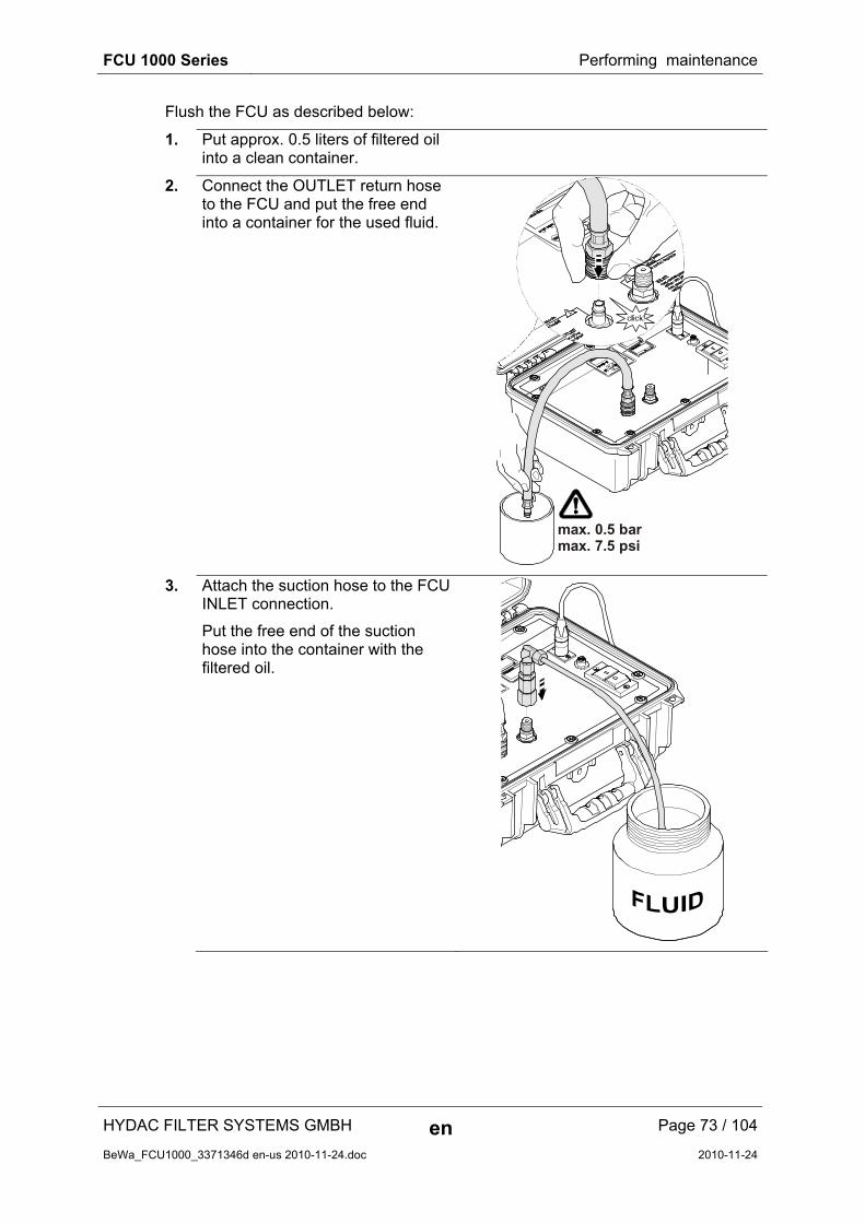
FCU 1000 Series Performing maintenance
HYDAC FILTER SYSTEMS GMBH en Page 73 / 104
BeWa_FCU1000_3371346d en-us 2010-11-24.doc 2010-11-24
Flush the FCU as described below:
1. Put approx. 0.5 liters of filtered oil into a clean container.
2. Connect the OUTLET return hose to the FCU and put the free end into a container for the used fluid.
max. 0.5 barmax. 7.5 psi
3. Attach the suction hose to the FCU INLET connection.
Put the free end of the suction hose into the container with the filtered oil.

FCU 1000 Series Performing maintenance
HYDAC FILTER SYSTEMS GMBH en Page 74 / 104
BeWa_FCU1000_3371346d en-us 2010-11-24.doc 2010-11-24
4. Use the switch on the FCU to turn its pump on.
5. Cleanliness values will be displayed during the flushing procedure.
These measurements are not correct, but should decrease during the flushing procedure.
Contamination
SAE/NAS
1)3
3/8
2=1(15
6. Once the 0.5 liters have been sucked up, switch off the pump.
7. The FCU is ready for operation.

FCU 1000 Series Performing maintenance
HYDAC FILTER SYSTEMS GMBH en Page 75 / 104
BeWa_FCU1000_3371346d en-us 2010-11-24.doc 2010-11-24
Clean the suction strainer.
NOTICE
Operation without a suction sieve
The FCU pump can be damaged
► Never use the FCU without a suction screen.
► Clean the suction screen regularly.
The sieve is fitted under the INLET connector and protects the pump from contamination by coarse particles.
Clean the suction screen regularly. If the FCU is blocked or there is no flow through, clean the sieve immediately.
To check/clean the sieve, proceed as follows:
1. Remove all of the hydraulic and electrical connections to the FCU.
2. Loosen the inlet connector, with a 19 mm wrench, turning it anticlockwise.
3. Unscrew the INLET connector manually, turning it anticlockwise.
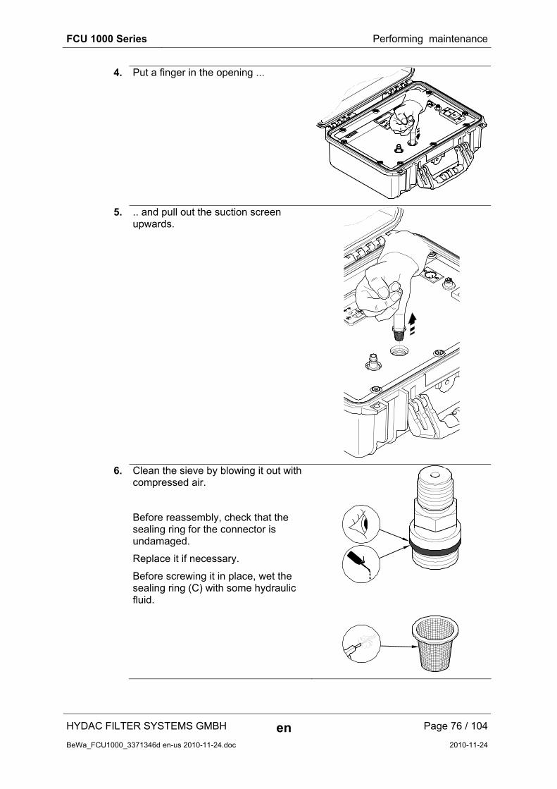
FCU 1000 Series Performing maintenance
HYDAC FILTER SYSTEMS GMBH en Page 76 / 104
BeWa_FCU1000_3371346d en-us 2010-11-24.doc 2010-11-24
4. Put a finger in the opening ...
5. .. and pull out the suction screen upwards.
6. Clean the sieve by blowing it out with compressed air.
Before reassembly, check that the sealing ring for the connector is undamaged.
Replace it if necessary.
Before screwing it in place, wet the sealing ring (C) with some hydraulic fluid.

FCU 1000 Series Performing maintenance
HYDAC FILTER SYSTEMS GMBH en Page 77 / 104
BeWa_FCU1000_3371346d en-us 2010-11-24.doc 2010-11-24
7. Put the sieve back into the opening.
8. Manually screw the INLET connector in clockwise.
9. Using a 19 mm wrench, tighten the INLET connector, turning it clockwise.
Note the maximum torque of 25 Nm.

FCU 1000 Series Performing maintenance
HYDAC FILTER SYSTEMS GMBH en Page 78 / 104
BeWa_FCU1000_3371346d en-us 2010-11-24.doc 2010-11-24
Checking the high pressure adaptor
In the high pressure adapter there is a 400 µm sieve to protect the flow control valve. Clean this sieve at least every 6 months, or more frequently if heavy soiling makes it necessary.
The flow rate through the high-pressure adapter is regulated to approx. 0-55 to 0.7 l/min.
If the necessary flow rate is not reached, you must check the sieve in the adapter and clean it.
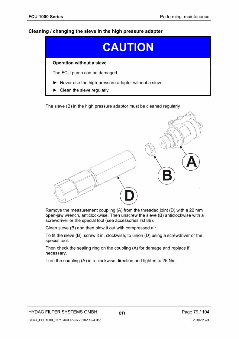
FCU 1000 Series Performing maintenance
HYDAC FILTER SYSTEMS GMBH en Page 79 / 104
BeWa_FCU1000_3371346d en-us 2010-11-24.doc 2010-11-24
Cleaning / changing the sieve in the high pressure adapter
CAUTION
Operation without a sieve
The FCU pump can be damaged
► Never use the high-pressure adapter without a sieve.
► Clean the sieve regularly
The sieve (B) in the high pressure adaptor must be cleaned regularly
BD
A
Remove the measurement coupling (A) from the threaded joint (D) with a 22 mm open-jaw wrench, anticlockwise. Then unscrew the sieve (B) anticlockwise with a screwdriver or the special tool (see accessories list 86).
Clean sieve (B) and then blow it out with compressed air.
To fit the sieve (B), screw it in, clockwise, to union (D) using a screwdriver or the special tool.
Then check the sealing ring on the coupling (A) for damage and replace if necessary.
Turn the coupling (A) in a clockwise direction and tighten to 25 Nm.
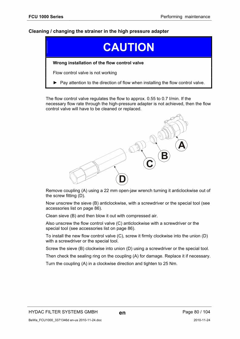
FCU 1000 Series Performing maintenance
HYDAC FILTER SYSTEMS GMBH en Page 80 / 104
BeWa_FCU1000_3371346d en-us 2010-11-24.doc 2010-11-24
Cleaning / changing the strainer in the high pressure adapter
CAUTION
Wrong installation of the flow control valve
Flow control valve is not working
► Pay attention to the direction of flow when installing the flow control valve.
The flow control valve regulates the flow to approx. 0.55 to 0.7 l/min. If the necessary flow rate through the high-pressure adapter is not achieved, then the flow control valve will have to be cleaned or replaced.
BA
C
D
Remove coupling (A) using a 22 mm open-jaw wrench turning it anticlockwise out of the screw fitting (D).
Now unscrew the sieve (B) anticlockwise, with a screwdriver or the special tool (see accessories list on page 86).
Clean sieve (B) and then blow it out with compressed air.
Also unscrew the flow control valve (C) anticlockwise with a screwdriver or the special tool (see accessories list on page 86).
To install the new flow control valve (C), screw it firmly clockwise into the union (D) with a screwdriver or the special tool.
Screw the sieve (B) clockwise into union (D) using a screwdriver or the special tool.
Then check the sealing ring on the coupling (A) for damage. Replace it if necessary.
Turn the coupling (A) in a clockwise direction and tighten to 25 Nm.
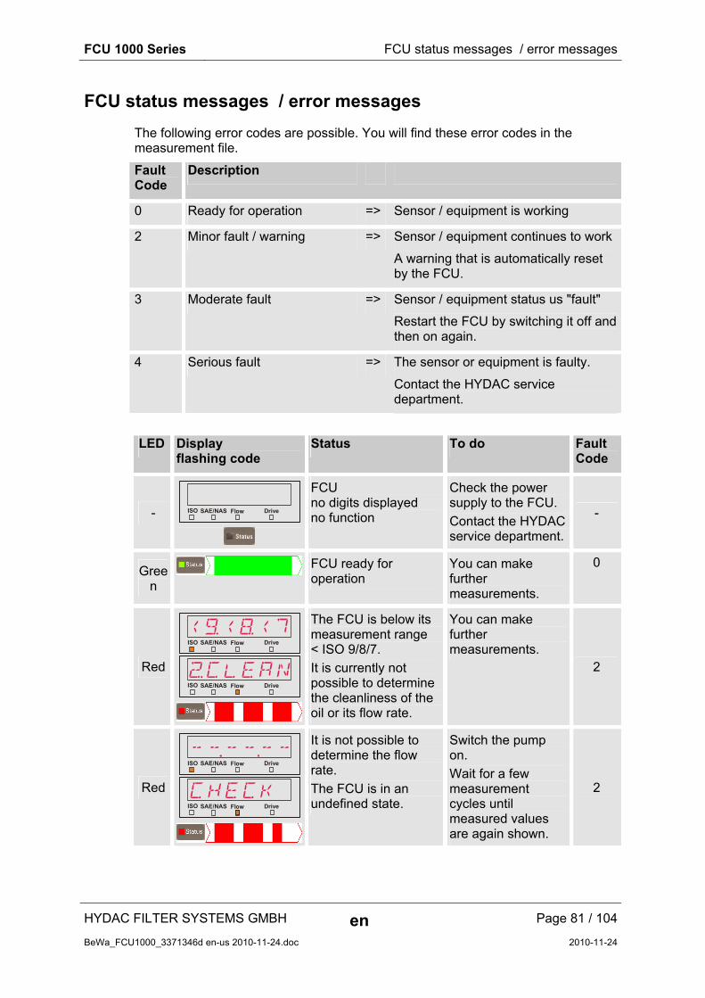
FCU 1000 Series FCU status messages / error messages
HYDAC FILTER SYSTEMS GMBH en Page 81 / 104
BeWa_FCU1000_3371346d en-us 2010-11-24.doc 2010-11-24
FCU status messages / error messages
The following error codes are possible. You will find these error codes in the measurement file.
Fault Code
Description
0 Ready for operation => Sensor / equipment is working
2 Minor fault / warning => Sensor / equipment continues to work
A warning that is automatically reset by the FCU.
3 Moderate fault => Sensor / equipment status us "fault"
Restart the FCU by switching it off and then on again.
4 Serious fault => The sensor or equipment is faulty.
Contact the HYDAC service department.
LED Display flashing code
Status To do Fault Code
- ISO Flow DriveSAE/NAS
FCU no digits displayed no function
Check the power supply to the FCU.
Contact the HYDAC service department.
-
Green
FCU ready for operation
You can make further measurements.
0
Red
<)<(<7
„CLEAN
ISO
ISO
Flow
Flow
Drive
Drive
SAE/NAS
SAE/NAS
The FCU is below its measurement range < ISO 9/8/7.
It is currently not possible to determine the cleanliness of the oil or its flow rate.
You can make further measurements.
2
Red
------
CHECK
ISO
ISO
Flow
Flow
Drive
Drive
SAE/NAS
SAE/NAS
It is not possible to determine the flow rate.
The FCU is in an undefined state.
Switch the pump on.
Wait for a few measurement cycles until measured values are again shown.
2

FCU 1000 Series FCU status messages / error messages
HYDAC FILTER SYSTEMS GMBH en Page 82 / 104
BeWa_FCU1000_3371346d en-us 2010-11-24.doc 2010-11-24
LED Display flashing code
Status To do Fault Code
Red
2%2$23
„DIRTY
ISO
ISO
Flow
Flow
Drive
Drive
SAE/NAS
SAE/NAS
The FCU is above its range of measurement > ISO 25/24/23.
It is currently not possible to determine the cleanliness of the oil or its flow rate.
Filter the oil to improve its cleanliness.
2
Red
NoSENSISO Flow DriveSAE/NAS
No ContaminationSensor is attached.
Switch the FCU off and back on again.
If the fault recurs, contact HYDAC service department.
3
Red ERRORISO Flow DriveSAE/NAS
The ContaminationSensor is causing a moderate fault.
Switch the FCU off.
If the fault recurs, contact HYDAC service department.
3
Red ERRORISO Flow DriveSAE/NAS
The ContaminationSensor is causing a major fault.
Contact the HYDAC service department.
4
Red
OUT
RNGE
The AquaSensor is outside of its measurement range.
Wait for a few more measurement cycles.
2
Red
No
SENS
No AquaSensor is connected.
Switch the FCU off and then on again.
If the fault recurs, contact HYDAC service department. 3

FCU 1000 Series FCU status messages / error messages
HYDAC FILTER SYSTEMS GMBH en Page 83 / 104
BeWa_FCU1000_3371346d en-us 2010-11-24.doc 2010-11-24
LED Display flashing code
Status To do Fault Code
Red
EROR
EROR
The AquaSensor is causing a moderate fault.
Switch the FCU off and then on again.
If the fault recurs, contact HYDAC service department. 3
LED Display flashing code
Status / To do
Fault Code
Red
Contamination
SAE/NAS
NoSENS No
SENS
No sensors are attached to the FCU. /
Switch the FCU off and then on again.
If the fault recurs, contact HYDAC service department.
3
Red
Contamination
SAE/NAS
ERROR FCU
The FCU has a moderate fault. /
Switch the FCU off and then on again.
If the fault recurs, contact HYDAC service department.
3
Red
Contamination
SAE/NAS
ERROR FCU
The FCU has a major fault. /
Contact the HYDAC service department.
4

FCU 1000 Series Restart / Resetting the FCU
HYDAC FILTER SYSTEMS GMBH en Page 84 / 104
BeWa_FCU1000_3371346d en-us 2010-11-24.doc 2010-11-24
Restart / Resetting the FCU
To reset the FCU, remove the power supply to the FCU for 10 seconds.
To remove the connector To insert the connector
24V DC
Press the catch on the connector (1) and then pull the connector out (2).
Insert the connector into the socket until it audibly snaps in.
Disposing of the FCU
Dispose of the packaging material as appropriate for your area.
When decommissioning and/or disposing of the unit, observe all local guidelines and regulations pertaining to occupational safety and environmental protection. This applies in particular to the oil in the unit, components covered with oil and electronical components.
After disassembling the unit and separating the various materials, reuse them or dispose of them properly in accordance with local regulations.

FCU 1000 Series Spare Parts List
HYDAC FILTER SYSTEMS GMBH en Page 85 / 104
BeWa_FCU1000_3371346d en-us 2010-11-24.doc 2010-11-24
Spare Parts List
Part no. Description Figure
349150 INLET high pressure hose with screwed joint, for measurement point type 1620, color: black, L = 2 m (78.74 inch)
3297276 INLET suction hose with open end, color: clear-transparent, Length = 1.5 m (59.06 inch)
349151 OUTLET return hose, open end, transparent, length = 2 m
278475 Suction strainer, 400 µm (for INLET port)
607755 Seal ring for INLET test point union (Ø 21 mm, according to DIN3869)
3364502 High pressure adaptor, complete
3152786 Suction strainer, 400 µm for high pressure adaptor 710389 Flow control valve for high pressure adaptor
3455429 Cover seal for case
3335656 Attachable bag for hoses, cables and accessories
3377173 Document folder for Operating and Maintenance instructions / Calibration certificate
3371346 Operation and Maintenance Instructions FCU 1000 (this document)
3546511 FCU 1000 "Getting started" guide

FCU 1000 Series Spare Parts List
HYDAC FILTER SYSTEMS GMBH en Page 86 / 104
BeWa_FCU1000_3371346d en-us 2010-11-24.doc 2010-11-24
Part no. Description Figure
6059933 Power adaptor (without power cord) primary: 100-240 V AC secondary: 24 V DC, 5A, cable with 3-pole plug, Length = 1.6 m (62.99 inch)
6008448 Connection cable for power adaptor European plug, Length = 2 m (78.74 inch)
6008447 Connection cable for power adaptor plug for England (UK), Length = 2 m (78.74 inch)
6008446 Connection cable for power adaptor plug for USA, Length = 2 m (78.74 inch)
6008449 Connection cable for power adaptor plug for Australia (AUS), Length = 2 m (78.74 inch)
Accessories for the FCU
Part no. Description Figure
3 4 4 3 2 5 3 FieldVerification Start-Up Kit
3 4 4 3 2 4 9 FieldVerification Kit
3325744 INLET suction hose with open end, color: clear-transparent, Length = 1.5 m (59.06 inch)
3306236 12V/24V DC cable with universal plug, including 8A fuse, Length = 10 m (393.7 inches)

FCU 1000 Series Spare Parts List
HYDAC FILTER SYSTEMS GMBH en Page 87 / 104
BeWa_FCU1000_3371346d en-us 2010-11-24.doc 2010-11-24
Part no. Description Figure
3524138 12V/24V DC cable with universal plug, including 8A fuse, Length = 1 m (39.37 inches)
6052824 Fuse 8 A for universal plug (Ø 6 x 25 mm, according to DIN 72581)
6051653 Battery adaptor for 12V/24V DC with coupling for universal plug, Length = 0.3 m (11.8 inches)
+
-
3209986 Tool to change the flow control valve in the high pressure adaptor
6074886 Bluetooth USB adaptor
3442973 USB Memory stick
3504605 BatteryPack, 24 V DC / 4500 mAh
3409462 CSI-B-2 kit ConditionSensor interface
X2
1
1
2
2
3
3
44
5
56
78
RS
485
CS
I-B
-2
RS
232
6019455 Connection cable, screened, with 5-pole connector, socket plug, bent, open, length 2 m (ZBE 08S-02)
6019456
Connection cable, screened, with 5-pole elbow female connector, open cable end, length 5 m (ZBE 08S-05)
6023102 Connection cable, screened, with 5-pole connector, socket plug, bent, open, length 10 m (ZBE 08S-10)
6040851 Connection cable with 5-pole connector <–> 5-pole socket, length 2 m (ZBE 30-02)
6053924
Connection cable with 5-way female connector <-> 5-way male connector Length 3 m (ZBE 30-03)
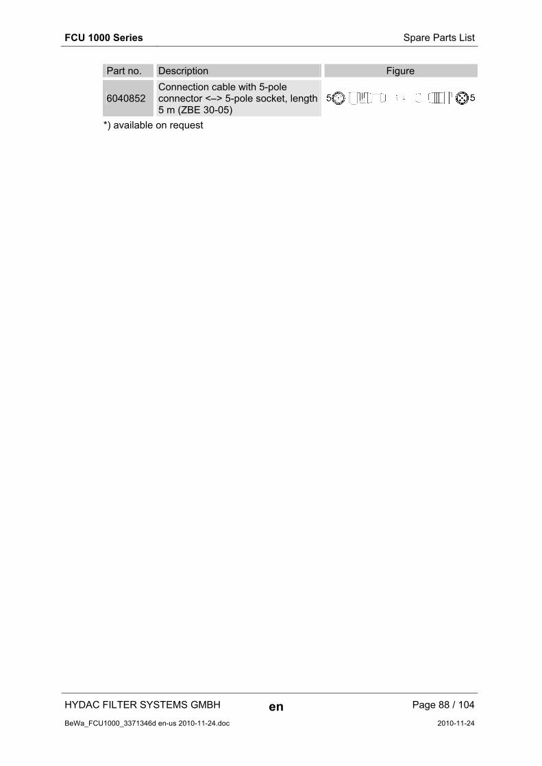
FCU 1000 Series Spare Parts List
HYDAC FILTER SYSTEMS GMBH en Page 88 / 104
BeWa_FCU1000_3371346d en-us 2010-11-24.doc 2010-11-24
Part no. Description Figure
6040852 Connection cable with 5-pole connector <–> 5-pole socket, length 5 m (ZBE 30-05)
*) available on request
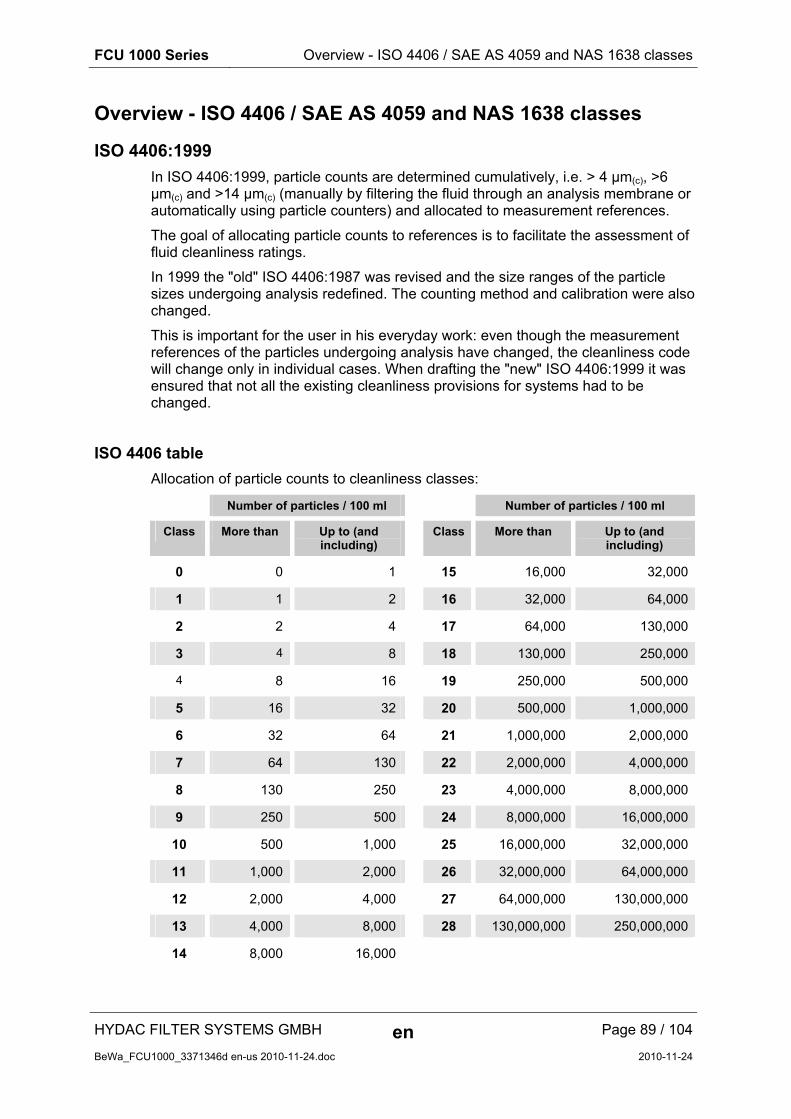
FCU 1000 Series Overview - ISO 4406 / SAE AS 4059 and NAS 1638 classes
HYDAC FILTER SYSTEMS GMBH en Page 89 / 104
BeWa_FCU1000_3371346d en-us 2010-11-24.doc 2010-11-24
Overview - ISO 4406 / SAE AS 4059 and NAS 1638 classes
ISO 4406:1999
In ISO 4406:1999, particle counts are determined cumulatively, i.e. > 4 µm(c), >6 µm(c) and >14 µm(c) (manually by filtering the fluid through an analysis membrane or automatically using particle counters) and allocated to measurement references.
The goal of allocating particle counts to references is to facilitate the assessment of fluid cleanliness ratings.
In 1999 the "old" ISO 4406:1987 was revised and the size ranges of the particle sizes undergoing analysis redefined. The counting method and calibration were also changed.
This is important for the user in his everyday work: even though the measurement references of the particles undergoing analysis have changed, the cleanliness code will change only in individual cases. When drafting the "new" ISO 4406:1999 it was ensured that not all the existing cleanliness provisions for systems had to be changed.
ISO 4406 table
Allocation of particle counts to cleanliness classes:
Number of particles / 100 ml Number of particles / 100 ml
Class More than Up to (and including)
Class More than Up to (and including)
0 0 1 15 16,000 32,000
1 1 2 16 32,000 64,000
2 2 4 17 64,000 130,000
3 4 8 18 130,000 250,000
4 8 16 19 250,000 500,000
5 16 32 20 500,000 1,000,000
6 32 64 21 1,000,000 2,000,000
7 64 130 22 2,000,000 4,000,000
8 130 250 23 4,000,000 8,000,000
9 250 500 24 8,000,000 16,000,000
10 500 1,000 25 16,000,000 32,000,000
11 1,000 2,000 26 32,000,000 64,000,000
12 2,000 4,000 27 64,000,000 130,000,000
13 4,000 8,000 28 130,000,000 250,000,000
14 8,000 16,000
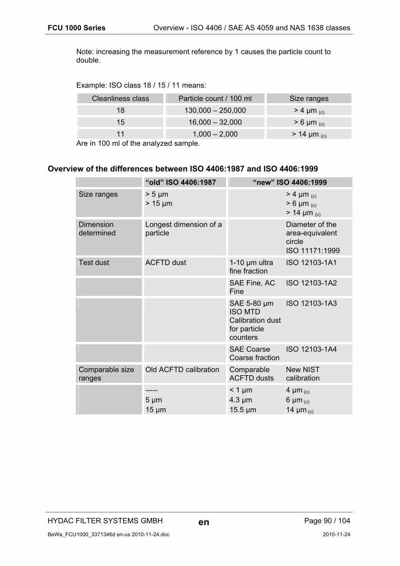
FCU 1000 Series Overview - ISO 4406 / SAE AS 4059 and NAS 1638 classes
HYDAC FILTER SYSTEMS GMBH en Page 90 / 104
BeWa_FCU1000_3371346d en-us 2010-11-24.doc 2010-11-24
Note: increasing the measurement reference by 1 causes the particle count to double.
Example: ISO class 18 / 15 / 11 means:
Cleanliness class Particle count / 100 ml Size ranges
18 130,000 – 250,000 > 4 µm (c)
15 16,000 – 32,000 > 6 µm (c)
11 1,000 – 2,000 > 14 µm (c) Are in 100 ml of the analyzed sample.
Overview of the differences between ISO 4406:1987 and ISO 4406:1999
“old” ISO 4406:1987 “new” ISO 4406:1999
Size ranges > 5 µm > 15 µm
> 4 µm (c) > 6 µm (c) > 14 µm (c)
Dimension determined
Longest dimension of a particle
Diameter of the area-equivalent circle ISO 11171:1999
Test dust ACFTD dust 1-10 µm ultra fine fraction
ISO 12103-1A1
SAE Fine, AC Fine
ISO 12103-1A2
SAE 5-80 µm ISO MTD Calibration dust for particle counters
ISO 12103-1A3
SAE Coarse Coarse fraction
ISO 12103-1A4
Comparable size ranges
Old ACFTD calibration Comparable ACFTD dusts
New NIST calibration
----- < 1 µm 4 µm (c) 5 µm 4.3 µm 6 µm (c) 15 µm 15.5 µm 14 µm (c)
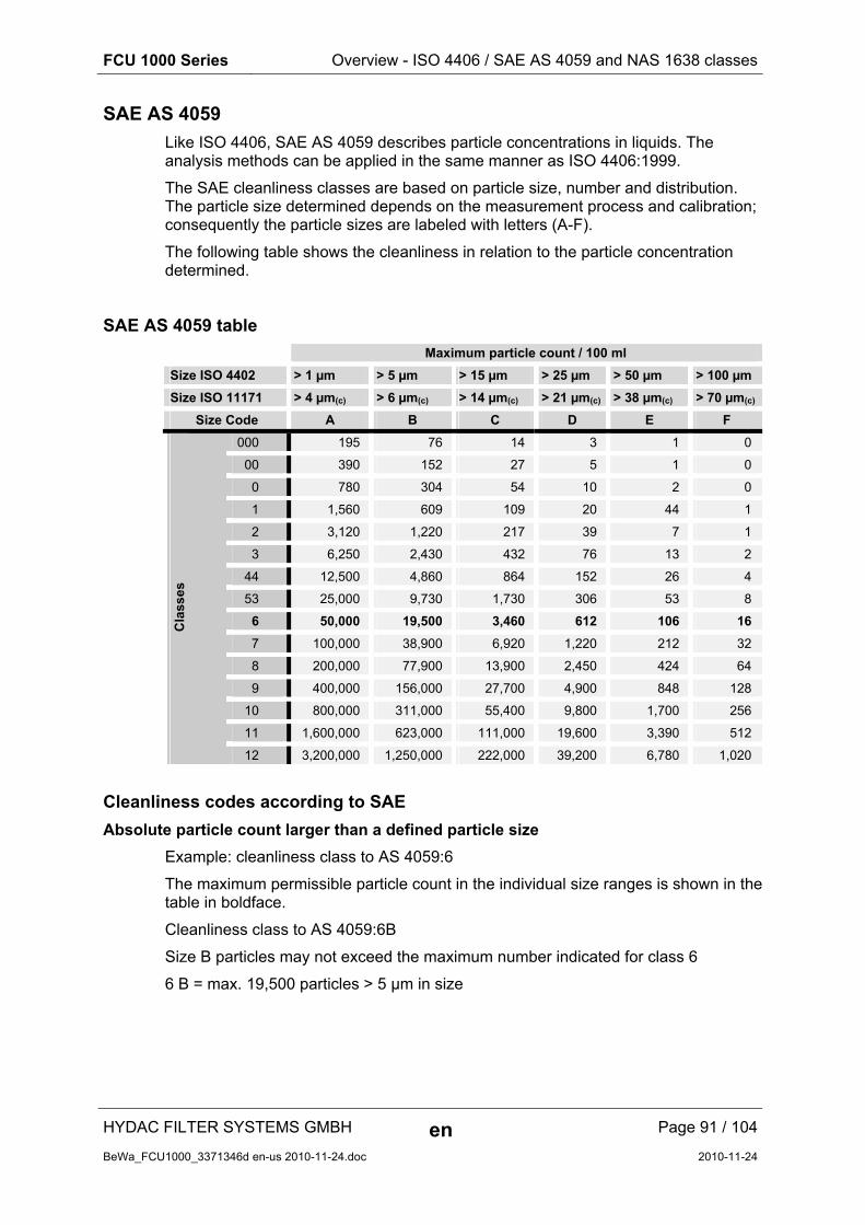
FCU 1000 Series Overview - ISO 4406 / SAE AS 4059 and NAS 1638 classes
HYDAC FILTER SYSTEMS GMBH en Page 91 / 104
BeWa_FCU1000_3371346d en-us 2010-11-24.doc 2010-11-24
SAE AS 4059
Like ISO 4406, SAE AS 4059 describes particle concentrations in liquids. The analysis methods can be applied in the same manner as ISO 4406:1999.
The SAE cleanliness classes are based on particle size, number and distribution. The particle size determined depends on the measurement process and calibration; consequently the particle sizes are labeled with letters (A-F).
The following table shows the cleanliness in relation to the particle concentration determined.
SAE AS 4059 table
Maximum particle count / 100 ml
Size ISO 4402 > 1 µm > 5 µm > 15 µm > 25 µm > 50 µm > 100 µm
Size ISO 11171 > 4 µm(c) > 6 µm(c) > 14 µm(c) > 21 µm(c) > 38 µm(c) > 70 µm(c)
Size Code A B C D E F
000 195 76 14 3 1 0
00 390 152 27 5 1 0
0 780 304 54 10 2 0
1 1,560 609 109 20 44 1
2 3,120 1,220 217 39 7 1
3 6,250 2,430 432 76 13 2
44 12,500 4,860 864 152 26 4
53 25,000 9,730 1,730 306 53 8
6 50,000 19,500 3,460 612 106 16
7 100,000 38,900 6,920 1,220 212 32
8 200,000 77,900 13,900 2,450 424 64
9 400,000 156,000 27,700 4,900 848 128
10 800,000 311,000 55,400 9,800 1,700 256
11 1,600,000 623,000 111,000 19,600 3,390 512
Cla
sses
12 3,200,000 1,250,000 222,000 39,200 6,780 1,020
Cleanliness codes according to SAE
Absolute particle count larger than a defined particle size
Example: cleanliness class to AS 4059:6
The maximum permissible particle count in the individual size ranges is shown in the table in boldface.
Cleanliness class to AS 4059:6B
Size B particles may not exceed the maximum number indicated for class 6
6 B = max. 19,500 particles > 5 µm in size

FCU 1000 Series Overview - ISO 4406 / SAE AS 4059 and NAS 1638 classes
HYDAC FILTER SYSTEMS GMBH en Page 92 / 104
BeWa_FCU1000_3371346d en-us 2010-11-24.doc 2010-11-24
Specifying a cleanliness class for each particle size
Example: cleanliness class to AS 4059: 7 A / 7 B / 6 C / 5 D
Cleanliness class Particle count / 100 ml
Size A ( > 1 µm / > 4 µm(c)) 100,000
Size B ( > 5 µm / > 6 µm(c)) 38,900
Size C ( > 15 µm / > 14 µm(c)) 3460
Size D ( > 25 µm / > 21 µm(c)) 306
Specifying the highest cleanliness code measured
Example: Cleanliness Class according to AS 4059 6 A – F
The 6 A – F specification requires a particle count in size ranges A – F. The respective particle concentration of cleanliness class 6 may not be exceeded in any of these ranges
NAS 1638
Like ISO 4406, NAS 1638 describes particle concentrations in liquids. The analysis methods can be applied in the same manner as ISO 4406:1999.
In contrast to ISO 4406, certain particle ranges are counted in NAS 1638 and attributed to measurement references.
The following table shows the cleanliness in relation to the particle concentration determined.
Maximum particle count / 100 ml 2..5 µm 5..15 µm 15..25 µm 25..50 µm 50..100 µm > 100 µm
00 625 125 22 45 1 0
0 1,250 250 44 8 2 0
1 2,500 500 88 16 53 1
2 5,000 1,000 178 32 6 1
3 10,000 2,000 356 64 11 2
4 20,000 4,000 712 128 22 4
45 40,000 8,000 1,425 253 45 8
6 80,000 16,000 2,850 506 90 16
7 160,000 32,000 5,700 1,012 180 32
8 320,000 64,000 11,400 2,025 360 64
9 640,000 128,000 22,800 4,050 720 128
10 1,280,000 256,000 45,600 8,100 1,440 256
11 2,560,000 512,000 91,200 16,200 2,880 512
12 5,120,000 1,024,000 182,400 32,400 5,760 1,024
13 10,240,000 2,048,000 364,800 64,800 11,520 2,048
Cle
anlin
ess
clas
s
14 20,480,000 4,096,000 729,000 129,600 23,040 4,096
Increasing the class by 1 causes the particle count to double on average.

FCU 1000 Series Checking the measuring accuracy of the FCU
HYDAC FILTER SYSTEMS GMBH en Page 93 / 104
BeWa_FCU1000_3371346d en-us 2010-11-24.doc 2010-11-24
Checking the measuring accuracy of the FCU
With the help of the FieldVerification Kit, you can check the error of measurement of the FluidControl Unit FCU 1000 on site based on a fluid defined as contaminated. Based on these results, you can decide whether you have the FCU 1000 recalibrated or extend the period of its use.
The part no. for the FieldVerification Kit can be found in the accessories list.
The use of the FCU 1000 Field Verification Kit does not eliminate the need for factory recalibration.
Calibrating the FCU
Recalibrate the FCU according to ISO 9000 standard.
We recommend a recalibration of the FCU at least every 3 years.

FCU 1000 Series Customer service
HYDAC FILTER SYSTEMS GMBH en Page 94 / 104
BeWa_FCU1000_3371346d en-us 2010-11-24.doc 2010-11-24
Customer service
Current contacts for product support/customer service, repair and spare parts can always be found on our website at www.hydac.com.
For calibration, contact one of the following HYDAC national subsidiaries:
Germany
HYDAC Service GmbH Product Support, Werk 10 66128 Saarbrücken, Germany
Telephone: +49 (0) 6897 509 883
Telefax: ++4499 ((00)) 66889977 550099 332244
E-mail: [email protected]
USA
HYDAC Technology Corporation, HYCON Division 2260 City Line Road USA-Bethlehem, PA 18017 P.O. Box 22050 USA-Lehigh Valley, PA 18002-2050 Telephone: +1 (0) 610 266 01 00
Telefax: +1 (0) 610 231 04 45
E-mail: [email protected]
Internet: www.hydacusa.com
Australia
HYDAC Pty. Ltd. 109 Dohertys Road P.O. Box 224 AUS-3025 Altona North
Telephone: +61 - 3 - 92 72 89 00
Fax: +61 - 3 - 93 69 89 12
E-mail: [email protected]
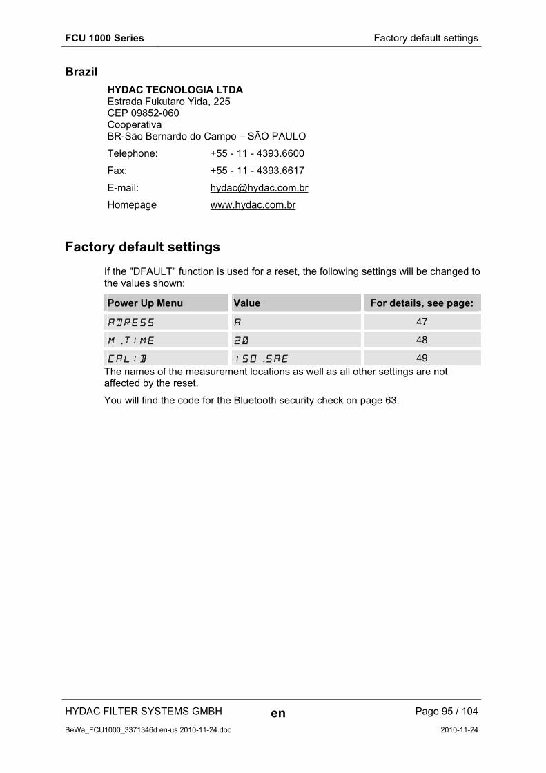
FCU 1000 Series Factory default settings
HYDAC FILTER SYSTEMS GMBH en Page 95 / 104
BeWa_FCU1000_3371346d en-us 2010-11-24.doc 2010-11-24
Brazil
HYDAC TECNOLOGIA LTDA Estrada Fukutaro Yida, 225 CEP 09852-060 Cooperativa BR-São Bernardo do Campo – SÃO PAULO
Telephone: +55 - 11 - 4393.6600
Fax: +55 - 11 - 4393.6617
E-mail: [email protected]
Homepage www.hydac.com.br
Factory default settings
If the "DFAULT" function is used for a reset, the following settings will be changed to the values shown:
Power Up Menu Value For details, see page:
ADRESS A 47
M.TIME 20 48
CALIB ISO.SAE 49 The names of the measurement locations as well as all other settings are not affected by the reset.
You will find the code for the Bluetooth security check on page 63.
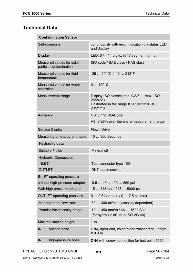
FCU 1000 Series Technical Data
HYDAC FILTER SYSTEMS GMBH en Page 96 / 104
BeWa_FCU1000_3371346d en-us 2010-11-24.doc 2010-11-24
Technical Data
Contamination Sensor
Self-diagnosis continuously with error indication via status LED and display
Display LED, 6 / 4 / 4 digits, in 17 segment format
Measured values for solid particle contamination
ISO code / SAE class / NAS class
Measured values for fluid temperature
-25 … 100°C / -13 … 212°F
Measured values for water saturation
0 … 100 %
Measurement range Display ISO classes min. 9/8/7 … max. ISO 25/24/23 Calibrated in the range ISO 13/11/10 - ISO 23/21/18
Accuracy CS: ± 1/2 ISO-Code
AS: ≤ ±3% over the entire measurement range
Service Display Flow / Drive
Measuring time programmable 10 … 300 Seconds
Hydraulic data
Suitable Fluids Mineral oil
Hydraulic Connectors
INLET: Test connector type 1604
OUTLET: DN7 nipple socket
INLET operating pressure
without high-pressure adapter -0.5 … 45 bar / 0 … 650 psi
With high pressure adaptor 15 … 345 bar / 217 … 5000 psi
OUTLET operating pressure 0 … 0.5 bar max. / 0 … 7.5 psi max.
Measurement flow rate: 30 … 300 ml/min (viscosity dependent)
Permissible viscosity range 10 … 350 mm²/s / 46 … 1622 Sus
(for hydraulic oil up to ISO VG 68)
Maximal suction height 1 m
INLET suction hose DN4, open-end, color: clear-transparent, Length = 0.3 m
INLET high-pressure hose DN4 with screw connection for test point 1620,

FCU 1000 Series Technical Data
HYDAC FILTER SYSTEMS GMBH en Page 97 / 104
BeWa_FCU1000_3371346d en-us 2010-11-24.doc 2010-11-24
Contamination Sensor
color: black, Length = 2 m (78.74 inch)
OUTLET return hose DN7, open-end, color: clear-transparent, Length = 1 m
Electrical data
Supply voltage 24 V DC, ± 20%, residual ripple ≤ 10%
Power consumption / electricity 100 W max. / 4 A max.
IP class IP 50 (open, in operation) IP 67 (closed)
Protection class III (low voltage protection)
General data
Material of sealings FPM
Fluid temperature range 0° … +70° C / 32° … 158° F
Ambient temperature range 0° … +45° C / 32° … 113° F
Storage temperature range -40° … +80 C / -40° … 176° F
Relative humidity max. 90%, non-condensing
Weight ~ 13 kg
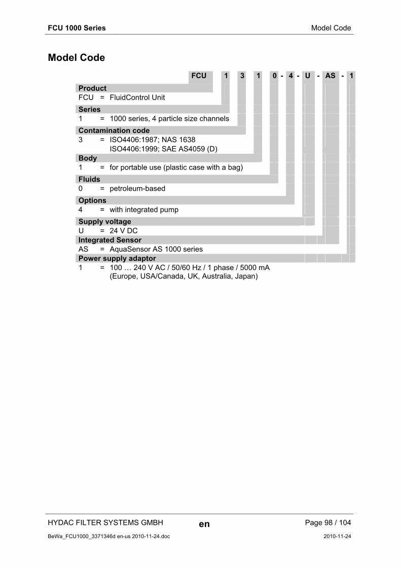
FCU 1000 Series Model Code
HYDAC FILTER SYSTEMS GMBH en Page 98 / 104
BeWa_FCU1000_3371346d en-us 2010-11-24.doc 2010-11-24
Model Code
FCU 1 3 1 0 - 4 - U - AS - 1
Product FCU = FluidControl Unit
Series 1 = 1000 series, 4 particle size channels
Contamination code 3 = ISO4406:1987; NAS 1638
ISO4406:1999; SAE AS4059 (D)
Body 1 = for portable use (plastic case with a bag)
Fluids 0 = petroleum-based
Options 4 = with integrated pump
Supply voltage U = 24 V DC Integrated Sensor AS = AquaSensor AS 1000 series Power supply adaptor 1 = 100 … 240 V AC / 50/60 Hz / 1 phase / 5000 mA
(Europe, USA/Canada, UK, Australia, Japan)

FCU 1000 Series Compatible USB sticks - overview
HYDAC FILTER SYSTEMS GMBH en Page 99 / 104
BeWa_FCU1000_3371346d en-us 2010-11-24.doc 2010-11-24
Compatible USB sticks - overview
In the following, you will find an overview of the USB memory sticks which we have tested with the FCU 1000 for compatibility, writing speed and stability in operation.
Manufacturer, name Type European Article Number (EAN)
Com
pat
ible
w
ith F
CU
10
00
Writ
e sp
eed
Sta
bilit
y
HYDAC (from the delivery) SanDisk 2GB Cruzer Micro SDCZ4-2048-E11 619659023034 Emtec Flash Drive USB 2.0 1GB EKMMD1GC150B 3126170043658 Hama Piko Business 1GB 00090845 4007249908452 Silicon Power 2GB Ultima-II SP002GBUF2M01V1S 4710700395035 Platinum ultra high performance 2GB 4027927775046
CnMemory USB-Stick 2GB 85114_2GB 4040348851144 Freecom Data Bar 1GB 29321 / 1GB 4021801293213 Intenso USBDRIVE 1GB 4034303006397 PNY attaché premium 4GB P-FD4GBA2M7-BX 3536401508618 Sony Microvault Click 2GB USM2GL 027242737105 Sony Microvault Click 2GB USM2GLX 027242737204 Transcend JetFlash T5 2GB TS2GJFT5T 0760557814030 TDK Trans-IT 2GB UFD-2GBUEBBL 4902030780036 ExcelStor Gstor Mini 8GB GSMS7008 6935758606102 CnMemory Micro X 512MB Transcend JetFlash V30 8GB Kingston Traveler Mini Slim 2GB DTMSB/2GB 740617131956 SanDisk 2GB Cruzer Micro SDCZ6-2048-E11WT 619659025724 Emtec Flash Drive USB 2.0 1GB EKMMD1GM200EM 3126170058126
Explanation:
Compatible with the FCU 1000 Excellent
Not compatible with the FCU 1000 Good
Ok
Bad

FCU 1000 Series EC declaration of conformity
HYDAC FILTER SYSTEMS GMBH en Page 100 / 104
BeWa_FCU1000_3371346d en-us 2010-11-24.doc 2010-11-24
EC declaration of conformity
HYDAC FILTER SYSTEMS GMBHPostfach 12 5166273 Sulzbach / SaarGermany
Industriegebiet66280 Sulzbach / SaarGermany
Telefon: ++49 (0) 6897 509 01Internet: www.hydac.com
EC declaration of conformity FS / 20 / 09 No.
We hereby declare that the following designated product, on the basis of its design and construction, and in the version which we have brought to market, corresponds to the fundamental safety and health requirements contained in the standards listed below.
Any modification of this product that is not coordinated with us in writing will cause this declaration to lose its validity.
Description FluidControl Unit
Type FCU1000 Series
Part no. -
Serial-no. -
EU Machinery Directive 2006/42/EG
EU Electrical Equipment Regulations 2006/95/EG
EMC Guideline 2004/108/EG
2009-12-01 Thorsten Trier Date Name (CE official)
Executive director: Documentation Representative:
Mathias Dieter, Dipl.Kfm. Wolfgang Haerin g Mr. Günter Harge
Registered seat of company: 66280 Sulzbach / Saar - Germany c/o HYDAC International GmbH, Industriegebiet, 66280 Sulzbach / Saar
Registry Court: Saarbrücken, HRB 17216 Telephone: ++49 (0) 6897 509 1511
Value added tax identification number : DE 815001609 Fax: ++49 (0) 6897 509 1394
Tax number : 040/110/50773 E-mail: [email protected]
Page 1 / 1


HYDAC FILTER SYSTEMS GMBH
Industriegebiet Postfach 1251
66280 Sulzbach/Saar 66273 Sulzbach/Saar
Germany Germany
Phone: +49 (0) 6897 509 01 Central
Fax: +49 (0) 6897 509 846 Technical Department
Fax: +49 (0) 6897 509 577 (Sales Department)
Internet: www.hydac.com
E-Mail: [email protected]
![[XLS]minoritywelfare.bih.nic.inminoritywelfare.bih.nic.in/scholarships/PreMatric/Fresh... · Web view1 1000 0 0 1000 2 1000 0 0 1000 3 1000 0 0 1000 4 1000 0 0 1000 5 1000 0 0 1000](https://img.pdfslide.us/doc/110x75/5ab4f6537f8b9a7c5b8c491e/xls-view1-1000-0-0-1000-2-1000-0-0-1000-3-1000-0-0-1000-4-1000-0-0-1000-5-1000.jpg)