Embed Size (px)
Citation preview
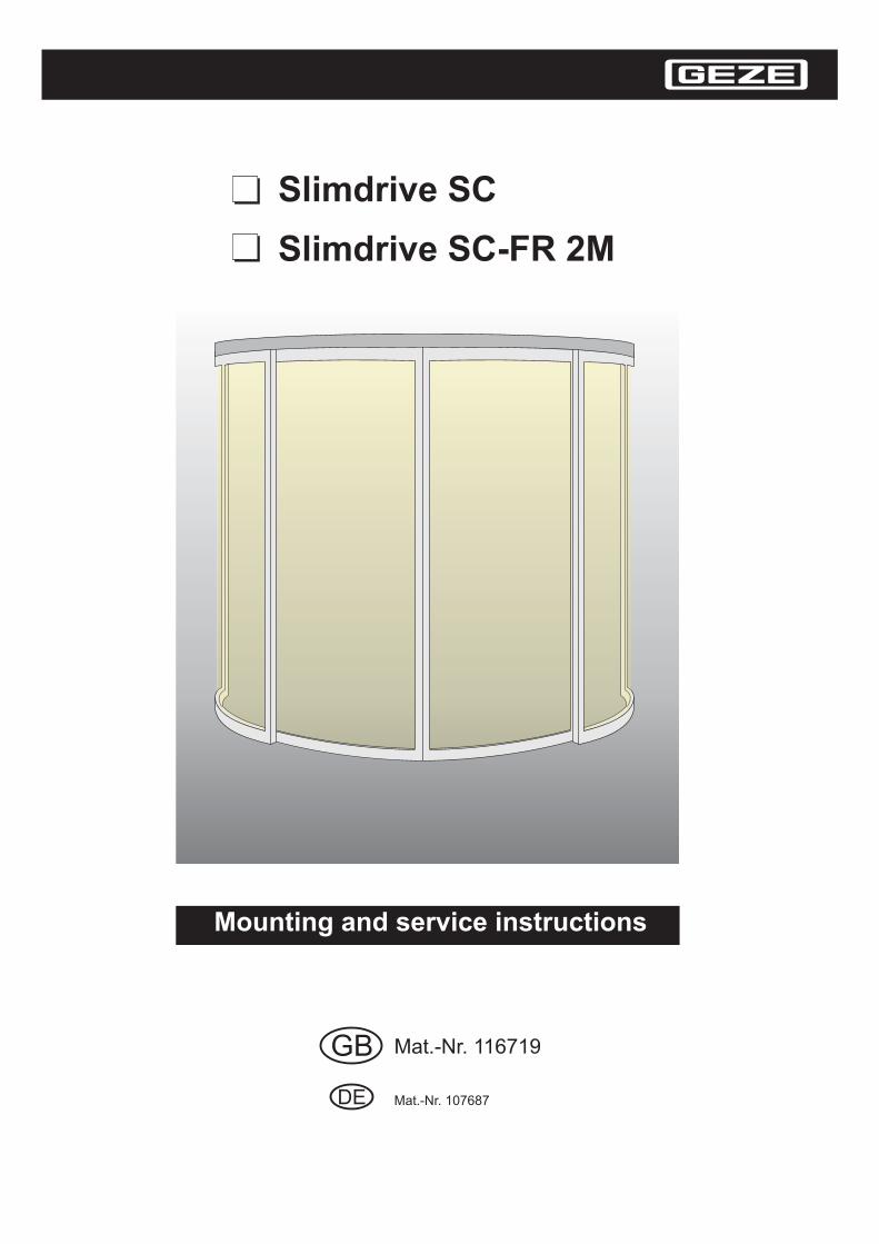
Mounting and service instructions
GB
Slimdrive SC
Slimdrive SC-FR 2M
Mat.-Nr. 116719
DE Mat.-Nr. 107687
1 Safety instruction 32 Overview 4
3 Assembly 9
4 Service mode 18
5 Servicing and maintenance 21
6 Troubleshooting 23
7 Index 26
2.1 Drawings 42.2 Tools 42.3 Torques 52.4 Structural components 52.5 Functional test 8
3.1 Checking the preparatory works to be provided by the customer 93.2 Fitting 93.3 Commissioning 143.4 Disassembly 17
4.1 Operation 184.2 Functions 184.3 Learning 194.4 Interlock or draught-proof system 20
5.1 Mechanical Service 215.2 Maintenance 22
6.1 Mechanical faults 236.2 Electric faults 24
Manufacturer’s declaration Slimdrive SC, SC-FR 2M 27
1 Contents
Description of symbols
means “work to be done”
means “important information”
means “additional information”
marks text that has to be read and observed by all means!Non-observance may cause injury to persons or damage to property!
Danger to life through electric shock!
2

1 Safety notes
Intended use
The and are only suitable for use- in dry rooms- in automatic door systems for horizontally moving door leaves- in entrances and interior areas with pedestrian traffic in commercial plants and public areasThe and may not be used as a fire or smoke protection door.The is approved for use in escape and rescue paths.The may not be used as an escape and rescue path door.
Slimdrive SC Slimdrive SC-FR 2M
Slimdrive SC Slimdrive SC-FR 2MSlimdrive SC-FR 2MSlimdrive SC
Safety precautions
- The described installation, maintenance and repair work must be performed by properly trainedpersonnel by GEZE.
- The country-specific laws and regulations are to be observed during safety-related tests.-
-
- The connection to the power supply must be made by a qualified electrician. Perform the powerconnection and equipment earth conductor test in accordance with VDE 0100 Part 610.
- Use a customer-accessible 10A overload cut-out as the line-side disconnecting device.- Protect the display programme switch from unauthorised access.- The detection field of the motion detector in the exiting direction must satisfy the AutSchR “Directive for
automatic windows, doors and gates” ( )- In accordance with the Machine Directive 98/37/EU, a danger analysis must be performed and the door
system identified in accordance with the CE Identification Directive 93/68/EEC before commissioning thedoor system.
- Observe the latest versions of guidelines, standards and country-specific regulations, in particular:- BGR 232 "Guidelines for power-operated windows, doors and gates"- VDE 0100, part 610 “Installation of electric power plants with nominal voltages up to 1000 V”
- AutSchR “Guideline for automatic windows, doors and gates”- Accident-prevention regulations, especially BGV A1 “General Regulations” and BGV A2 “Electrical
Installations and Devices”
Slimdrive SC-FR
GEZE shall not be liable for injuries or damage resulting from unauthorised modification of theequipment, and the approval for use in escape and rescue paths is voided when unauthorised changesare made (Slimdrive SC-FR 2M).GEZE is not liable if products from other manufacturers are used with GEZE equipment.
- Only original GEZE parts may be used for repair and maintenance work as well.
- DIN EN 60335-2-103 “Safety of electric devices for home use or similar purposesSpecial requirements for drives designed to move gates, doors and windows”
Safety-conscious working
- Secure workplace against unauthorised entry.
- Watch swinging area of long system parts.
- Never carry out work with a high safety risk (e.g. Installing the drive, hood or door leaf) while alone.
- Secure cover/drive shrouding against falling.
- Use only cables prescribed in the interconnection diagram. Lay screening in accordance with theconnection diagram.
- Secure loose, internal drive cables with cable ties.
- Before working on the electrical system:- disconnect the drive from the 230 V mains network and check to ensure that it is not supplied with
power.- disconnect the controller from the 24 V battery.- note that if an uninterruptible power supply (UPS) is used, the system will still be supplied with power
despite the fact that the power supply is disconnected.
- Always use insulated wire-end ferrules for wire cores.
- Attach safety labels to glass door leaves (Id.no. 081476).
- Danger of injury by opened drive. Hair, clothing, cables etc. can be pulled in by rotating parts!
- Danger of injury by unsecured pinching, impact, shearing or drawing-in spots!
- Danger of injury by broken glass!
- Danger of injury by sharp edges in the drive!
- Danger of injury during installation by freely moving parts!
3
Inspection of installed system:Measures for security and prevention of pinching, impact, shearing or drawing-in spots:
- Check the function of the safety sensors and motion detectors.- The detection field of the motion detector in exiting direction must cover the opening width x 1.5 m in
front of the door.- The motion detector in exiting direction (see AutSchR) must detect people moving faster than 0.1 m/s.- Check earth connection to all metal parts which can be touched.
Environmentally-conscious working
When disposing of the door systen, separate the different materials and have them recycled.Do not dispose of batteries and storage cells with household garbage.Comply with the statutory regulations when disposing of the door system and the batteries and storagecells.
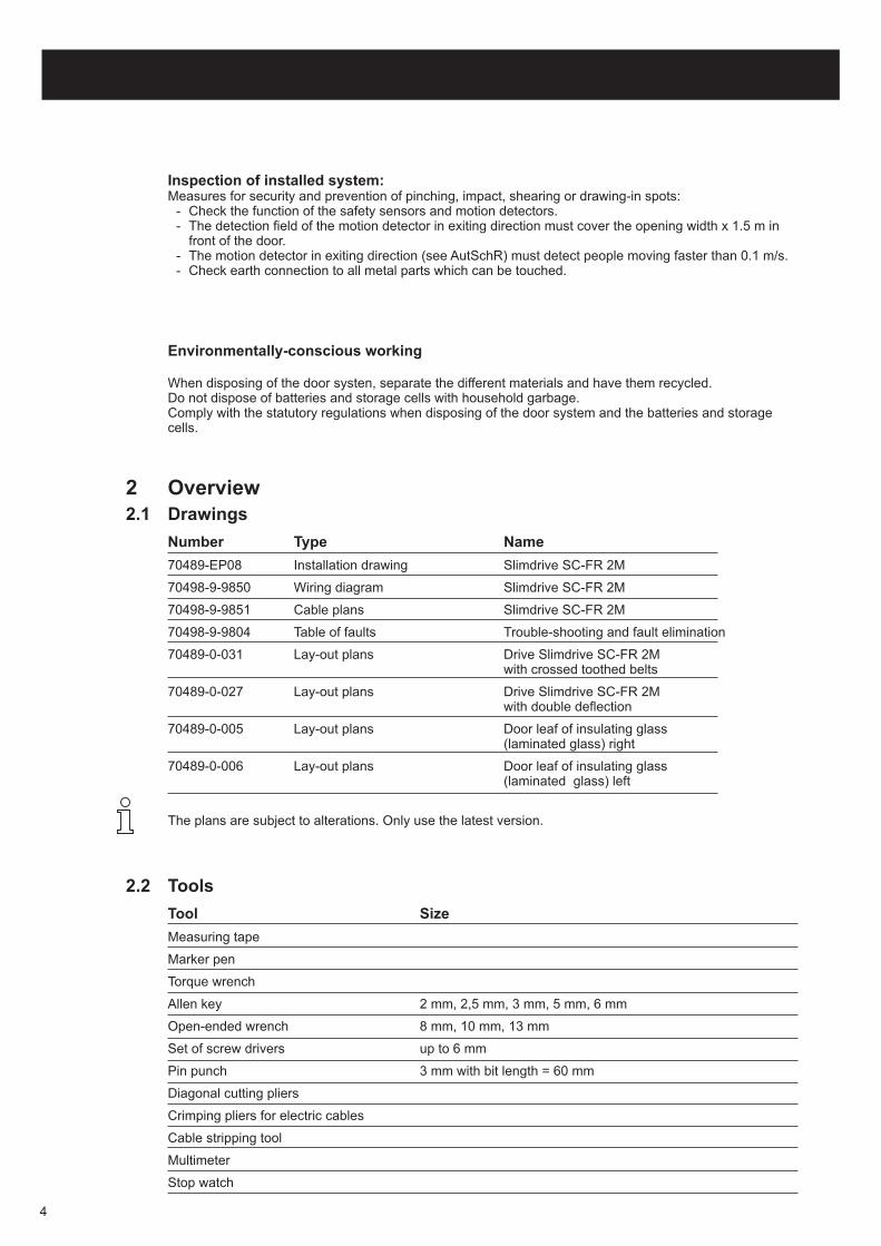
The plans are subject to alterations. Only use the latest version.
2 Overview
2.1 Drawings
Number Type Name
70489-EP08 Installation drawing Slimdrive SC-FR 2M
70498-9-9850 Wiring diagram Slimdrive SC-FR 2M
70498-9-9851 Cable plans Slimdrive SC-FR 2M
70498-9-9804 Table of faults Trouble-shooting and fault elimination
70489-0-031 Lay-out plans Drive Slimdrive SC-FR 2Mwith crossed toothed belts
70489-0-027 Lay-out plans Drive Slimdrive SC-FR 2Mwith double deflection
70489-0-005 Lay-out plans Door leaf of insulating glass(laminated glass) right
70489-0-006 Lay-out plans Door leaf of insulating glass(laminated glass) left
Tool Size
Measuring tape
Marker pen
Torque wrench
Allen key 2 mm, 2,5 mm, 3 mm, 5 mm, 6 mm
Open-ended wrench 8 mm, 10 mm, 13 mm
Set of screw drivers up to 6 mm
Pin punch 3 mm with bit length = 60 mm
Diagonal cutting pliers
Crimping pliers for electric cables
Cable stripping tool
Multimeter
Stop watch
2.2 Tools
4
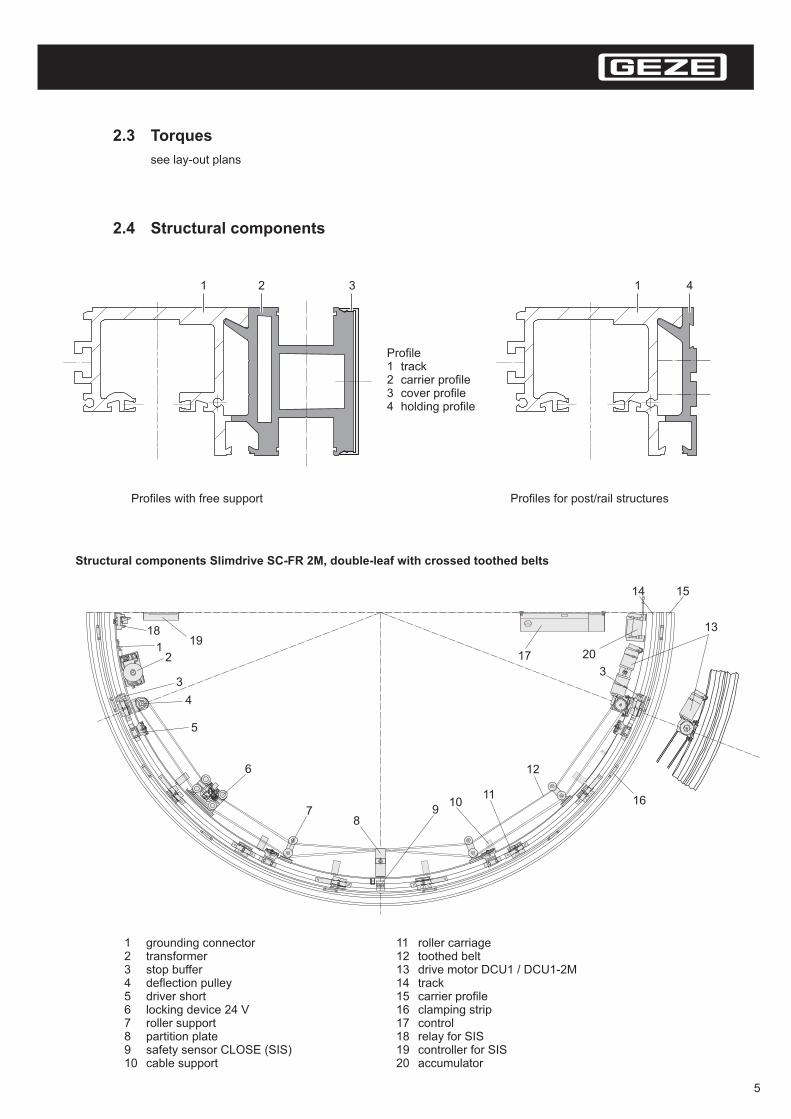
2.3 Torques
2.4 Structural components
see lay-out plans
1 41 2 3
Profile1 track23 cover profile4 holding profile
carrier profile
Profiles with free support Profiles for post/rail structures
TÜVThüringen
1
3
1819
2
4
5
6
78
910
11
12
13
17
14 15
16
20
3
1 grounding connector2 transformer3 stop buffer4 deflection pulley5 driver short6 locking device 24 V7 roller support8 partition plate9 safety sensor CLOSE (SIS)10 cable support
11 roller carriage12 toothed belt13 drive motor DCU1 / DCU1-2M14 track15 carrier profile16 clamping strip17 control18 relay for SIS19 controller for SIS20 accumulator
Structural components Slimdrive SC-FR 2M, double-leaf with crossed toothed belts
5
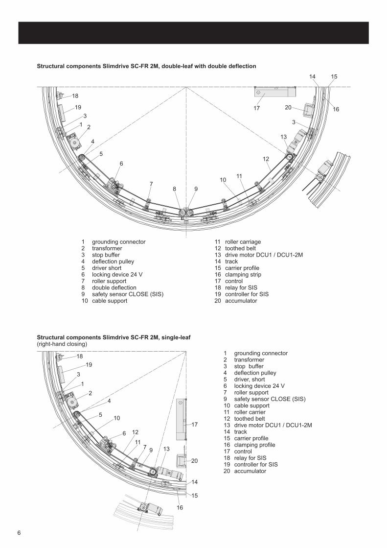
Structural components Slimdrive SC-FR 2M, single-leaf(right-hand closing)
TÜ
VT
hü
ring
en
1
24
5
6
7 9
10
11
12
13
16
15
14
20
17
3
19
18 1 grounding connector2 transformer3 stop buffer4 deflection pulley5 driver, short6 locking device 24 V7 roller support9 safety sensor CLOSE (SIS)10 cable support11 roller carrier12 toothed belt13 drive motor DCU1 / DCU1-2M14 track15 carrier profile16 clamping profile17 control18 relay for SIS19 controller for SIS20 accumulator
Structural components Slimdrive SC-FR 2M, double-leaf with double deflection
TÜVThüringen
1
3
18
19
2
4
5
6
78 9
1011
12
13
17
14 15
1620
3
1 grounding connector2 transformer3 stop buffer4 deflection pulley5 driver short6 locking device 24 V7 roller support8 double deflection9 safety sensor CLOSE (SIS)10 cable support
11 roller carriage12 toothed belt13 drive motor DCU1 / DCU1-2M14 track15 carrier profile16 clamping strip17 control18 relay for SIS19 controller for SIS20 accumulator
6

Periphery
floor guide area
safety sensor CLOSE (SIS) (e.g. light barriers, light curtains)
contact maker AUTHORISED (KB) for authorised opening (e.g. key-operated switch)
motion detector INTERIOR, contact maker EXTERIOR (KA)
display programme switch
key-operated button for display programme switch
emergency OFF switch (option)
main switch (option)
7
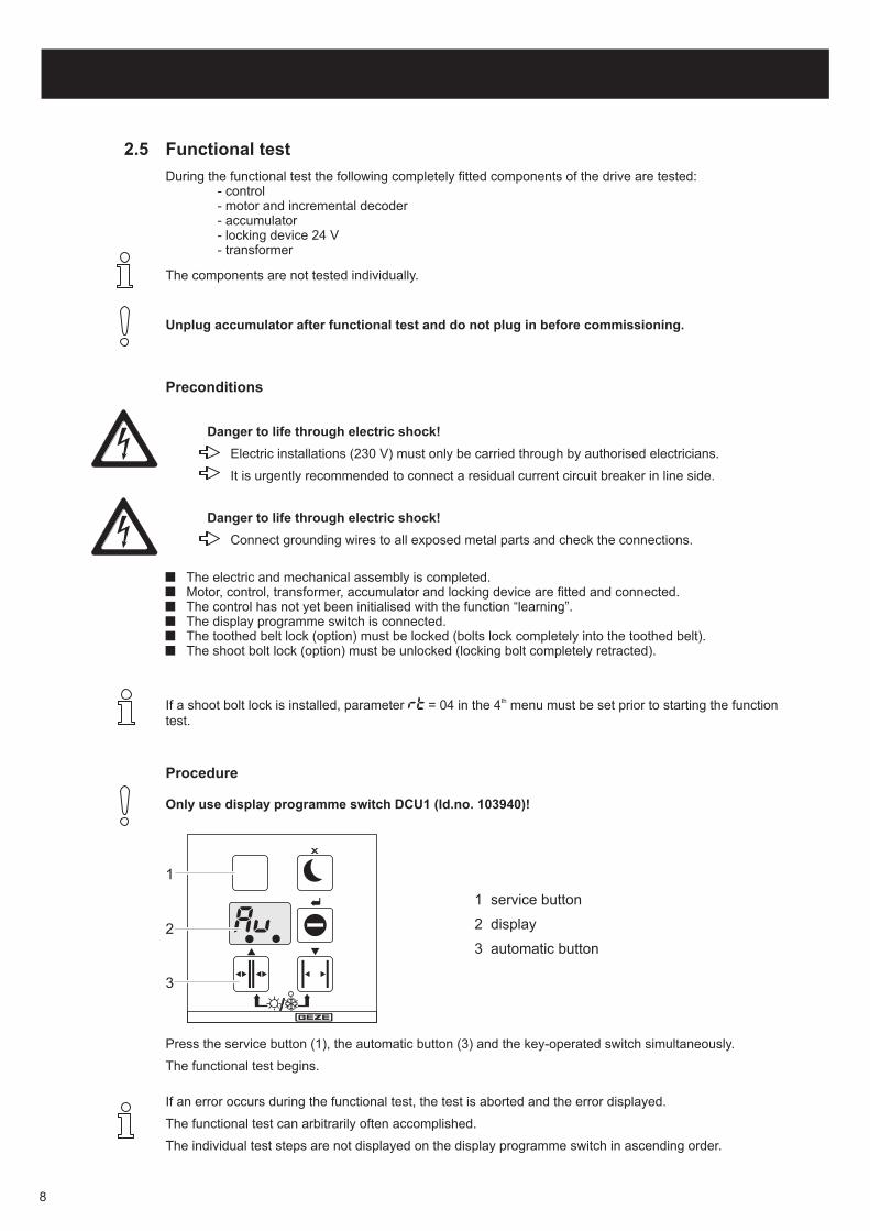
2.5 Functional test
1
2
3
1 service button
2 display
3 automatic button
During the functional test the following completely fitted components of the drive are tested:- control- motor and incremental decoder- accumulator- locking device 24 V- transformer
The components are not tested individually.
If a shoot bolt lock is installed, parameter = 04 in the 4 menu must be set prior to starting the functiontest.
th
If an error occurs during the functional test, the test is aborted and the error displayed.
The individual test steps are not displayed on the display programme switch in ascending order.
The functional test can arbitrarily often accomplished.
Press the service button (1), the automatic button (3) and the key-operated switch simultaneously.
The functional test begins.
Unplug accumulator after functional test and do not plug in before commissioning.
The electric and mechanical assembly is completed.Motor, control, transformer, accumulator and locking device are fitted and connected.The control has not yet been initialised with the function “learning”.The display programme switch is connected.The toothed belt lock (option) must be locked (bolts lock completely into the toothed belt).The shoot bolt lock (option) must be unlocked (locking bolt completely retracted).
Preconditions
Procedure
Danger to life through electric shock!
Electric installations (230 V) must only be carried through by authorised electricians.
It is urgently recommended to connect a residual current circuit breaker in line side.
Danger to life through electric shock!
Connect grounding wires to all exposed metal parts and check the connections.
Only use display programme switch DCU1 (Id.no. 103940)!
8
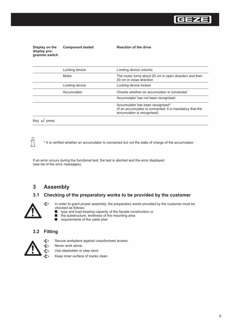
* It is verified whether an accumulator is connected but not the state of charge of the accumulator.
If an error occurs during the functional test, the test is aborted and the error displayed.(see list of the error messages).
Display on thedisplay pro-gramme switch
Component tested Reaction of the drive
Locking device unlocks
The motor turns about 20 cm in open direction and then20 cm in close direction
Locking device locked
Checks whether an accumulator is connected
Accumulator has not been recognised
Accumulator has been recognised*(if an accumulator is connected, it is mandatory that theaccumulator is recognised)
Locking device
Locking device
Accumulator
Key press
Motor
3 Assembly
3.1 Checking of the preparatory works to be provided by the customer
3.2 Fitting
In order to grant proper assembly, the preparatory works provided by the customer must bechecked as follows:
type and load-bearing capacity of the facade construction orthe substructure, levelness of the mounting arearequirements of the cable plan
Secure workplace against unauthorised access.
Keep inner surface of tracks clean.
Never work alone.
Use stepladder or step stool.
9

Fitting profiles
for post/rail construction:
1. Fit floor guide (see installation drawing).
2. Align holding profile with lower edge of rail (see installation drawing).
3. Drill bore holes in accordance with the local conditions.
4. Screw on holding profile (see installation drawing).
5. Prepare cable route in accordance with the local conditions, e.g. no holding profile at the markedposition.
6. Fit sealing strip in accordance with the local conditions (see installation drawing).
7. Brace track above the clamping strip by means of carrier profiles so that the track is no longer subjectto torsion:- insert clamping strip between the carrier profile and the track.- post/rail structure: position inner clamping strip and further clamping strips in between.- wall and ceiling installation: position inner clamping strips as required.
8. Connect cable for safety sensor CLOSE (SIS).
9. Lay cable for exterior motion detector: drill holding profile at a suitable position and draw in cable (seewiring diagram).
10. Fit covering panels.
for self-supporting beams:
1. Fit floor guide (see installation drawing).
2. Fit wall rail (see installation drawing).
3. Put side parts onto floor ring (see installation drawing).
4. Fit drive with holding profile onto side parts.
5. Prepare cable routing in accordance with the local conditions, e.g.:No holding profile for the beam at the marked position.
6. Connect cable for safety sensor (SIS).
7. Lay cable for the exterior motion detector: drill holding profile for beam at a suitable position and drawin cable (see wiring diagram).
8. Fit covering panels.
The running track must be clamped completely.
Danger of injury!
Any unsecured components may dislodge and fall down.
10
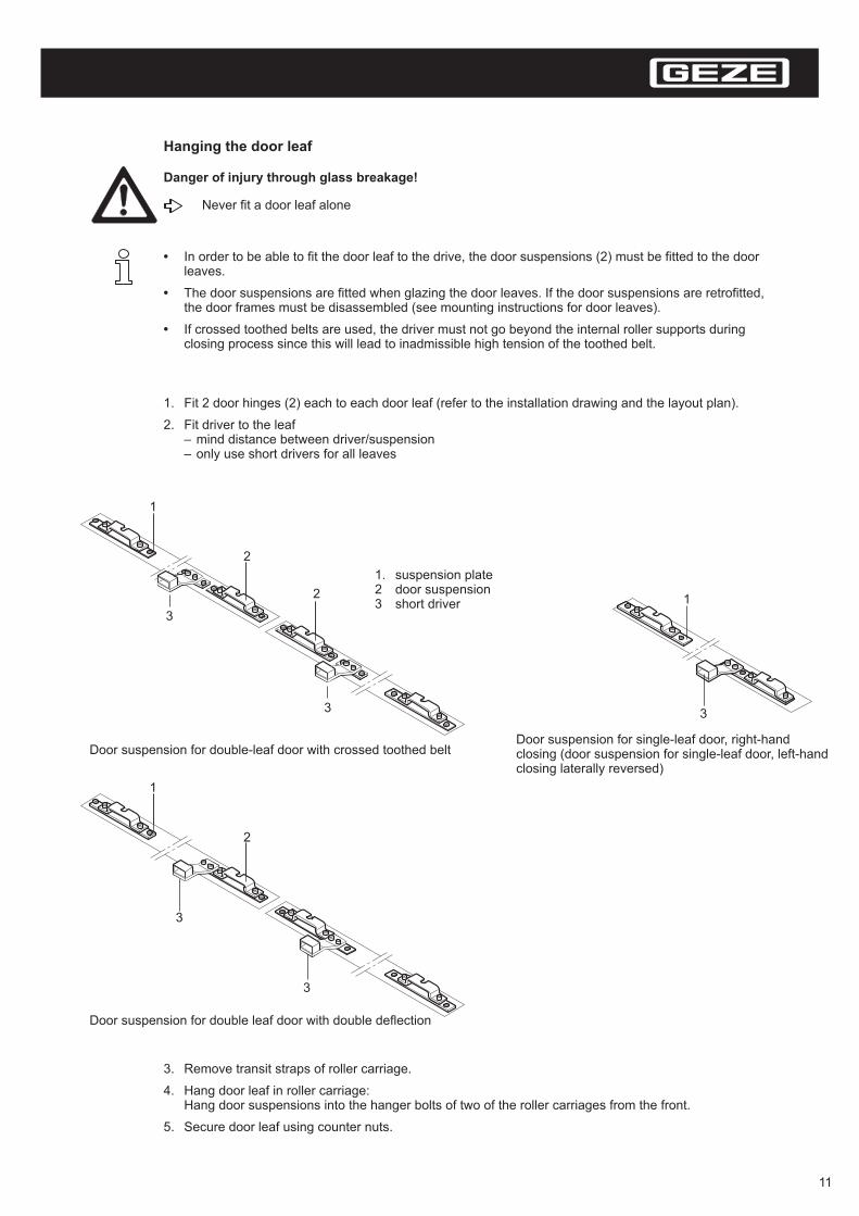
Hanging the door leaf
Never fit a door leaf alone
Danger of injury through glass breakage!
•
•
•
In order to be able to fit the door leaf to the drive, the door suspensions (2) must be fitted to the doorleaves.
The door suspensions are fitted when glazing the door leaves. If the door suspensions are retrofitted,the door frames must be disassembled (see mounting instructions for door leaves).
If crossed toothed belts are used, the driver must not go beyond the internal roller supports duringclosing process since this will lead to inadmissible high tension of the toothed belt.
1. Fit 2 door hinges (2) each to each door leaf (refer to the installation drawing and the layout plan).
2.–Fit driver to the leaf
mind distance between driver/suspension– only use short drivers for all leaves
3. Remove transit straps of roller carriage.
4. Hang door leaf in roller carriage:Hang door suspensions into the hanger bolts of two of the roller carriages from the front.
5. Secure door leaf using counter nuts.
1. suspension plate2 door suspension3 short driver
1
2
3
3
Door suspension for double leaf door with double deflection
1
3
Door suspension for single-leaf door, right-handclosing (door suspension for single-leaf door, left-handclosing laterally reversed)
1
2
2
3
3
Door suspension for double-leaf door with crossed toothed belt
11
The door leaves are still unsecured and can easily be moved.
Make sure that the door leaves cannot be moved unintentionally or by unauthorised persons.
Danger of trapping!
Aligning the door leaves
1. Adjust parallel position and height of the door leaf by adjusting the hexagonal hanger bolts:– ensure that each door leaf can be easily operated.– align door leaves flush with each other. Make sure that they have the same height and parallel
closing edges.– Secure door leaves with hexagon nuts against the hanger bolts.
2. Secure door leaf against leaving the track at the sides:Fix stop buffer to the left door leaf behind the left roller carriage.
3. Adjust stop buffer for the right roller carriage at the right door leaf.
Fit height adjustment
1. Insert brush into the height adjustment strip (refer to layout plan).
2. Insert height adjustment strip into the door leaf (refer to layout plan).
3. Fit floor guide (refer to layout plan).
4. Check door leaf for ease of operation.
Connect door leaf with system
1. Close door leaf and align centrally.
2. Move the toothed belt until the lock of the toothed belt and the driver overlap.
3. Connect driver and toothed belt lock.
The driver must not bump into the roller suspension!
It must be possible to move the door leaves by exerting a force of maximum 100 N.
If a higher effort is required to move the door leaf, the door leaf is stiff and has to be adjusted(see section 6.1).
If crossed toothed belts are employed, the driver must not go beyond the internal roller supports duringclosing process since this will lead to inadmissible high tension of the toothed belts.
12
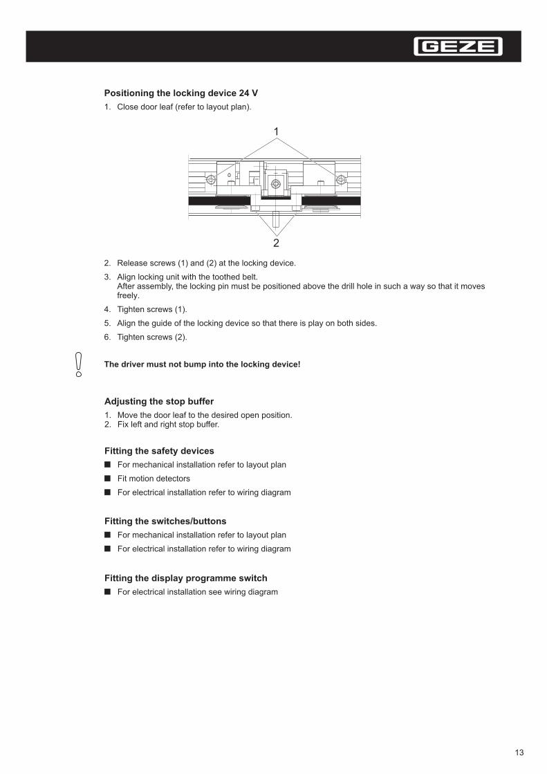
Positioning the locking device 24 V
1. Close door leaf (refer to layout plan).
2. Release screws (1) and (2) at the locking device.
3. Align locking unit with the toothed belt.After assembly, the locking pin must be positioned above the drill hole in such a way so that it movesfreely.
4. Tighten screws (1).
5. Align the guide of the locking device so that there is play on both sides.
6. Tighten screws (2).
The driver must not bump into the locking device!
Fitting the switches/buttons
For mechanical installation refer to layout plan
For electrical installation refer to wiring diagram
Fitting the display programme switch
For electrical installation see wiring diagram
Fitting the safety devices
For mechanical installation refer to layout plan
Fit motion detectors
For electrical installation refer to wiring diagram
Adjusting the stop buffer
1. Move the door leaf to the desired open position.2. Fix left and right stop buffer.
1
2
13
Fitting the key-operated switch
The key-operated switch can be used to lock/unlock the display programme switch
For electrical installation please refer to the wiring diagram
For Slimdrive SC-FR 2M, the key-operated button is mandatory!
For Slimdrive SL, the key-operated button can be installed as an option.
3.3 Commissioning
Danger to life through electric shock!
Electric installations (230 V) must only be carried through by authorised electricians.
The mains connection as well as the protective earth test should be carried out in accordancewith VDE 0100 part 610.
Connecting cables
1. Disconnect the system from 230 V network.
2. Neatly lay the cables in accordance with the cable layout plan:Use cable ties.
3. Make connections at the control in accordance with the wiring diagram.
4. Prior to commissioning remove the cables from the pathway of leaves and remove the driver andsecure with cable ties.
When using flexible cable, the end sleeve for strands should be insulated.
Starting the learning function
1. Plug the display programme switch into the control.
2. Clear the sensing range of all sensors.
3. Connect system to the 230 V network.At the first start-up, the control jumps to the learning function (see section 5.3) and the displayprogramme switch displays Then the display will show for a DCU1 control system( = standard door) or for a DCU1-2M control system ( = escape door) and after that the number
of the version, e.g. for version 1 revision 4.
If the control had already been in operation, start the learning mode by selecting in the service
LE.
14
LE
The door leaves move, all safety devices of the doors are switched off.
Step back from the path of travel of the doors.
Danger of trapping!
It is possible that revolving parts entrap hair, pieces of clothing or cable etc.!
When working with the drive open, watch out for any turning parts.
Risk of injury when the drive is open!
In order to be able to carry out the learning function properly, the door panels must be closed.
The accumulator must be completely charged.
Only use the display programme switch DCU1 (Id.no. 103940)!
14

4. Close door leaves.
5. Press key:– the door leaves open and close again.– the operating parameters are collected and saved.
The learning programme will run in accordance with section 5.3.
Checking the function
1. Switch of the system.
2. Switch the system back on.
3. Set the display programme switch to “AUTOMATIC”Self-testing will run automatically.
4. Check the function of components and periphery:
– safety sensor (SIS):if the light barrier/light curtain is interrupted, the door should not close after it has been activated.The door will close slowly after 4 minutes, issuing an error message.
– Safety sensor OPEN (SIO):e.g. check the function and the sensing range of the fixed field sensor.
– Contact maker INTERIOR (KB)
– Contact maker AUTHORISED (KB)
– Contact maker EXTERIOR (KA)
– Use the diagnostic function in the service mode (section 5.4) to check whether the control systemhas learnt the function of all connected components and safety devices.
– Check the locking function and adjust if necessary (section 4.2).
5. If the system does not function, check the voltages supply.Also refer to “Errors and troubleshooting” as well as to the error table.
6. If the display programme switch indicates move the door leaves by hand to a reduced opening andl6
– The door leaves will open and close again.
If the programme switch indicates or the learning programme has been completed and the door isLE Au
With the Slimdrive SF-FR 2M, a reduced opening width is only permitted if the reduced openingwidth is larger than the required width of the escape route .(see section 5.3)
15
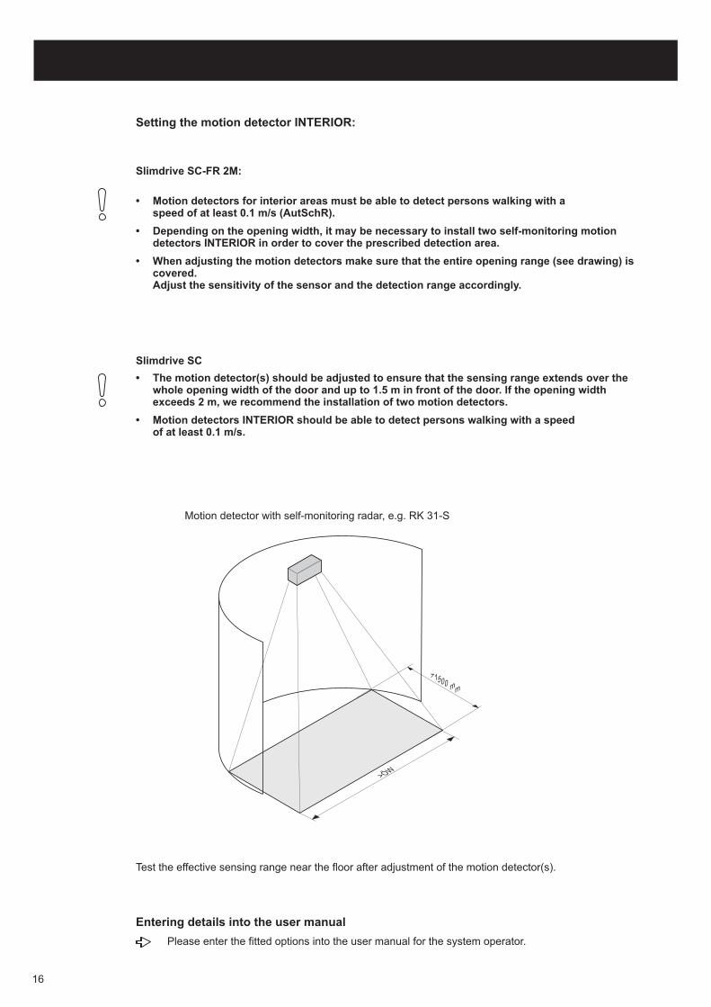
Setting the motion detector INTERIOR:
Slimdrive SC-FR 2M:
Slimdrive SC
• Motion detectors for interior areas must be able to detect persons walking with aspeed of at least 0.1 m/s (AutSchR).
• Depending on the opening width, it may be necessary to install two self-monitoring motiondetectors INTERIOR in order to cover the prescribed detection area.
• When adjusting the motion detectors make sure that the entire opening range (see drawing) iscovered.Adjust the sensitivity of the sensor and the detection range accordingly.
• The motion detector(s) should be adjusted to ensure that the sensing range extends over thewhole opening width of the door and up to 1.5 m in front of the door. If the opening widthexceeds 2 m, we recommend the installation of two motion detectors.
• Motion detectors INTERIOR should be able to detect persons walking with a speedof at least 0.1 m/s.
Test the effective sensing range near the floor after adjustment of the motion detector(s).
>ÖW
>1500 mm
Motion detector with self-monitoring radar, e.g. RK 31-S
Entering details into the user manual
Please enter the fitted options into the user manual for the system operator.
16
3.4 Disassembly
Pull out the height adjustable ledge before unhinging the door.
Do not put the door onto the height adjustable ledge.
There is a risk of damage to the height adjusting ledge!
Secure the door leaves against unintentional movement.
Unplug the accumulator.
Risk of trapping and impact injury!
Separate the electric system from the 230 V network prior to working on the system.
Danger to life through electric shock!
For disassemly proceed in the reverse order from assembly.
17
4 Service mode
4.1 Operation
Accessing the service mode:
access only via the display programme switch DCU (mat. no. 103940)
no access while system is in ‘night time’ operating mode
operation only possible when the key switch is activated (applies to DCU1-2M)
Service mode starts with first function in 1. menu (funktion ).
The service mode consists of 4 menus, which are subdivided into individual functions. Within thesefunctions several different settings are possible.
After each change the door leaves will open and close.
In the service mode the door will retain the current operating mode and will open and close accordingly.
Exception: functions and .
In the service mode the display programme switch buttons are assigned as follows:
Switching the service mode on and off
Operating the service mode
If no button is pressed for five minutes, the control system reverts to the normal operating mode.Exception: in the learning mode, in the diagnostic mode and when the motor has been released.
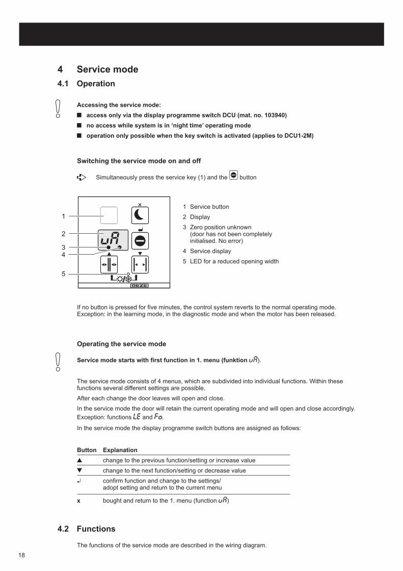
Simultaneously press the service key (1) and the button
1
2
34
5
1 Service button
2 Display
3 Zero position unknown(door has not been completelyinitialised. No error)
4 Service display
5 LED for a reduced opening width
Button Explanation
x
change to the previous function/setting or increase value
change to the next function/setting or decrease value
confirm function and change to the settings/adopt setting and return to the current menu
bought and return to the 1. menu (function )
4.2 Functions
The functions of the service mode are described in the wiring diagram.
18
The door will find its running parameters with the help of the learning function in the service mode.
The display programme switch will indicate the following steps:
Close the door leaves before starting the learning mode
For learning a reduced opening width the system operator has to produce written evidence of themandatory width of the escape route. Learning a reduced opening width is only permitted if thisdocument has been produced. The adjusted reduced opening width must be at least the width ofthe mandatory width of the escape route. A copy of the document is to be appended to theservice/inspection book.
The reduced opening width must not be less than 60% of the opening width. The control systemcannot learn any reduced position smaller than that.
The settings will not be displayed in ascending order.
Learning a reduced position for escape doors (DCU1-2M)
Cancelling learning process
The learning programme offers the option of learning a reduced opening width.
1. Before starting the learning programme, fit a jumper at the control system between terminals 2 and 6.
2. When the display programme switch indicates move the door to the desired position of thereduced opening width.
3. Press the button to adopt the position of the door.
4. Press the button to end the learning programme.
5. The jumper between terminals 2 and 6 must be removed again.
Checking:
1. Change the programme to “Automatic" .
2. Put the door into the operating mode for winter by simultaneously pressing the buttons and .
3. Activate the door or set to ‘reduced permanently open’ and then check the position by measuring witha tape measure.
Simultaneously press the service key and the button.
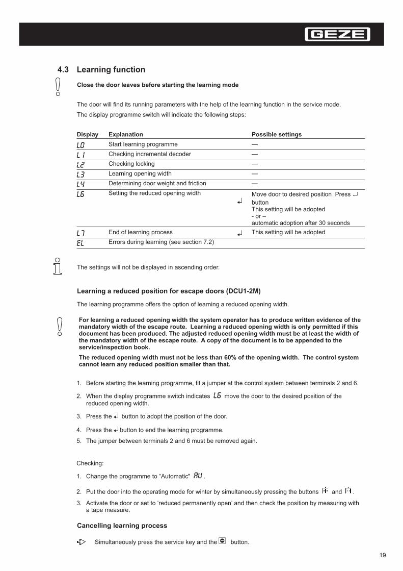
4.3 Learning function
Display Explanation
Start learning programme
Checking incremental decoder
Checking locking
Learning opening width
Determining door weight and friction
Setting the reduced opening width
End of learning process
Errors during learning (see section 7.2)
Possible settings
—
—
—
—
—
Move door to desired position Press
buttonThis setting will be adopted- or –automatic adoption after 30 seconds
↵
This setting will be adopted
19

4.4 Interlock or draught-proof system via a programme switch(only for DCU 1)
The functions interlock or draught-proof system is only available for standard sliding doors (DCU 1).
Interlock system: Two sliding doors use the same programme switch.One of the doors can only open if the other one is closed.
Draught-proof system: Two sliding doors use the same programme switch.
These functions are not admitted for sliding doors on escape routes (DCU 1-2M).
1. Take interior door (master) into operation. The exterior door (slave) is dead.
2. Switch off interior door.
3. Take exterior door (slave) into operation. The interior door is dead.
4. Set the value
for an interlock system or
for a draught-proof system
in the menu
5. Check whether the menu at the interior door displays the value .
6. Switch off the system and take both systems into operation simultaneously.
• If both systems are in operation, connect the voltage supply to the interior door only.
• When commissioning the exterior door, supply the display programme switch with the voltageof the exterior door.
Commissioning the interlock or draught-proof system:
The programme switch only displays the error messages of the master door.
20
5 Servicing and Maintenance
5.1 Mechanical Service
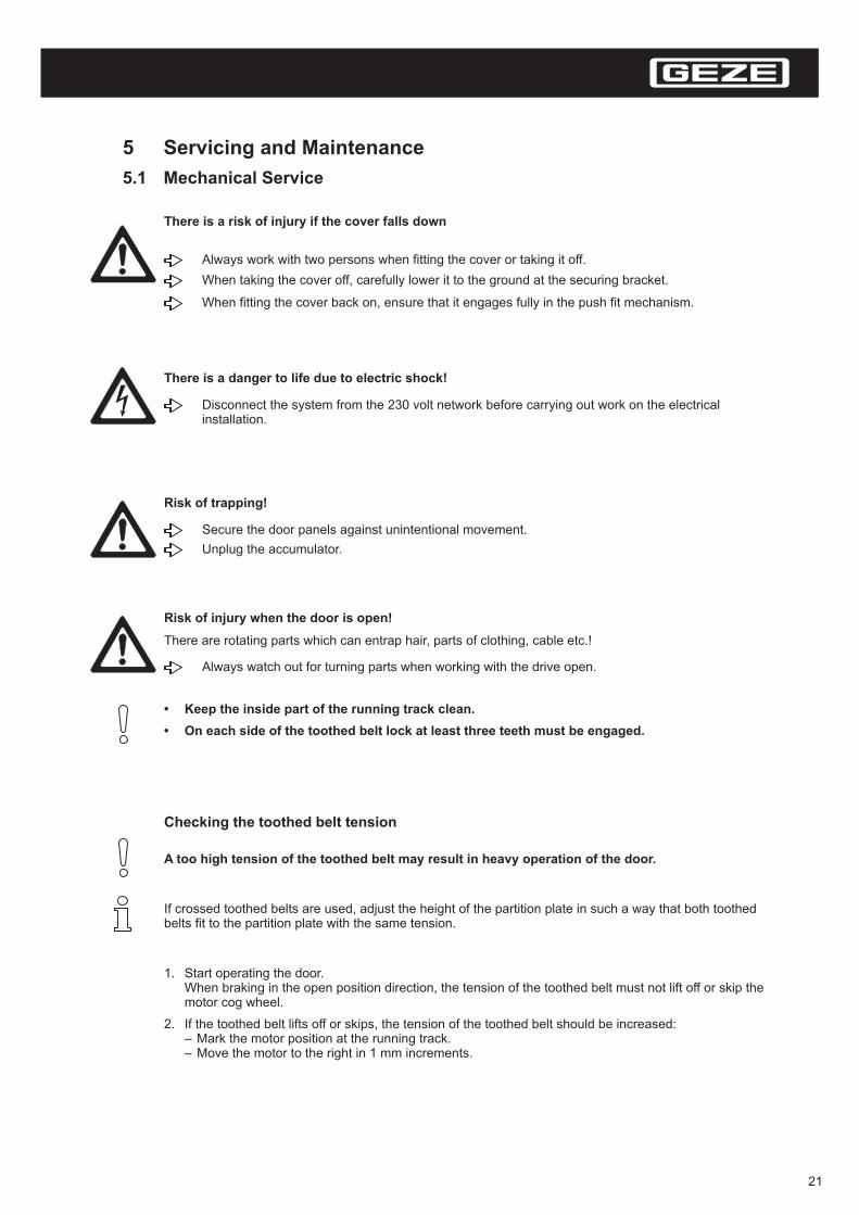
Always work with two persons when fitting the cover or taking it off.
When taking the cover off, carefully lower it to the ground at the securing bracket.
When fitting the cover back on, ensure that it engages fully in the push fit mechanism.
There is a risk of injury if the cover falls down
Secure the door panels against unintentional movement.
Unplug the accumulator.
Risk of trapping!
Disconnect the system from the 230 volt network before carrying out work on the electricalinstallation.
There is a danger to life due to electric shock!
Always watch out for turning parts when working with the drive open.
Risk of injury when the door is open!
There are rotating parts which can entrap hair, parts of clothing, cable etc.!
• Keep the inside part of the running track clean.
• On each side of the toothed belt lock at least three teeth must be engaged.
A too high tension of the toothed belt may result in heavy operation of the door.
Checking the toothed belt tension
1. Start operating the door.When braking in the open position direction, the tension of the toothed belt must not lift off or skip themotor cog wheel.
2. If the toothed belt lifts off or skips, the tension of the toothed belt should be increased:– Mark the motor position at the running track.– Move the motor to the right in 1 mm increments.
If crossed toothed belts are used, adjust the height of the partition plate in such a way that both toothedbelts fit to the partition plate with the same tension.
21
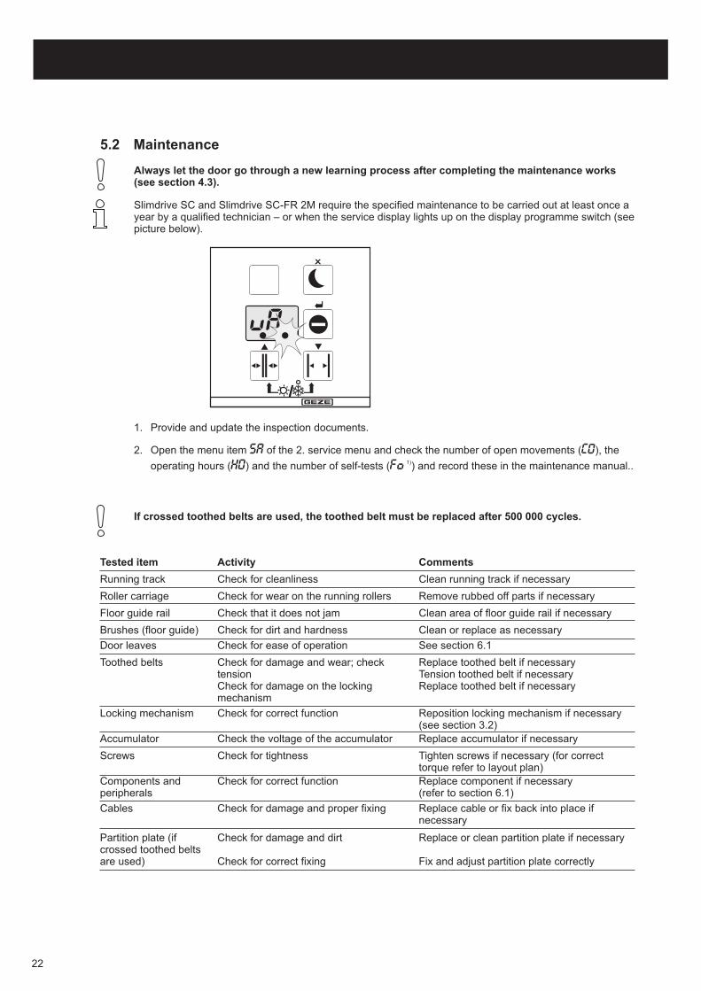
1. Provide and update the inspection documents.
2. Open the menu item of the 2. service menu and check the number of open movements ( ), the
operating hours ( ) and the number of self-tests ( ) and record these in the maintenance manual..1)
5.2 Maintenance
Slimdrive SC and Slimdrive SC-FR 2M require the specified maintenance to be carried out at least once ayear by a qualified technician – or when the service display lights up on the display programme switch (seepicture below).
Always let the door go through a new learning process after completing the maintenance works(see section 4.3).
If crossed toothed belts are used, the toothed belt must be replaced after 500 000 cycles.
Tested item
Running track
Roller carriage
Floor guide rail
Brushes (floor guide)
Door leaves
Toothed belts
Locking mechanism
Accumulator
Screws
Components andperipherals
Cables
Partition plate (ifcrossed toothed beltsare used)
Activity
Check for cleanliness
Check for wear on the running rollers
Check that it does not jam
Check for dirt and hardness
Check for ease of operation
Check for damage and wear; checktensionCheck for damage on the lockingmechanism
Check for correct function
Check the voltage of the accumulator
Check for tightness
Check for correct function
Check for damage and proper fixing
Check for damage and dirt
Check for correct fixing
Comments
Clean running track if necessary
Remove rubbed off parts if necessary
Clean area of floor guide rail if necessary
Clean or replace as necessary
See section 6.1
Replace toothed belt if necessaryTension toothed belt if necessaryReplace toothed belt if necessary
Reposition locking mechanism if necessary(see section 3.2)Replace accumulator if necessary
Tighten screws if necessary (for correcttorque refer to layout plan)Replace component if necessary(refer to section 6.1)
Replace cable or fix back into place ifnecessary
Replace or clean partition plate if necessary
Fix and adjust partition plate correctly
22
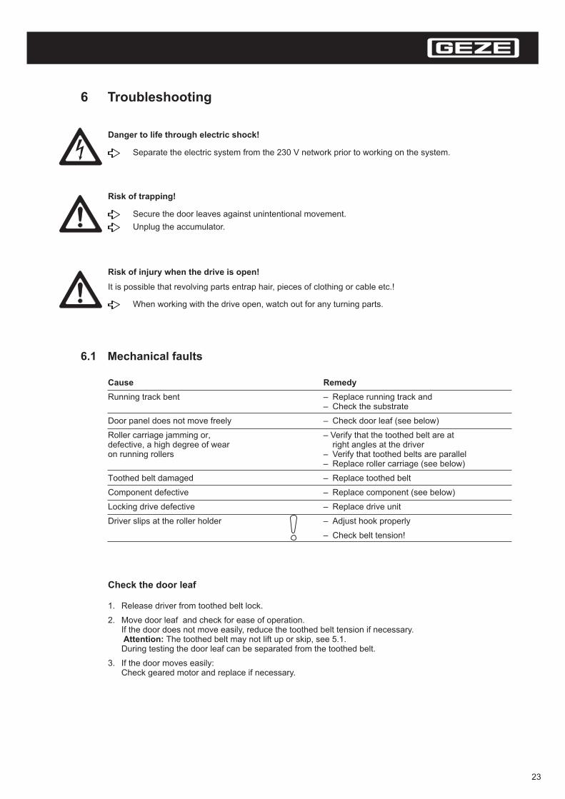
6 Troubleshooting
Secure the door leaves against unintentional movement.
Unplug the accumulator.
Risk of trapping!
Separate the electric system from the 230 V network prior to working on the system.
Danger to life through electric shock!
When working with the drive open, watch out for any turning parts.
Risk of injury when the drive is open!
It is possible that revolving parts entrap hair, pieces of clothing or cable etc.!
6.1 Mechanical faults
Check the door leaf
1. Release driver from toothed belt lock.
2. Move door leaf and check for ease of operation.If the door does not move easily, reduce the toothed belt tension if necessary.
The toothed belt may not lift up or skip, see 5.1.During testing the door leaf can be separated from the toothed belt.
3. If the door moves easily:Check geared motor and replace if necessary.
Attention:
Cause Remedy
Running track bent – Replace running track and– Check the substrate
Door panel does not move freely
, –
––
T
Check belt tension!
– Check door leaf (see below)
Roller carriage jamming or Verify that the toothed belt are atdefective, a high degree of wear right angles at the driveron running rollers Verify that toothed belts are parallel
Replace roller carriage (see below)
oothed belt damaged – Replace toothed belt
Component defective – Replace component (see below)
Locking drive defective – Replace drive unit
Driver slips at the roller holder – Adjust hook properly
–
23
Replace roller carriage
1. Detach driver from toothed belt lock.
2. Loosen counter nut at the suspension bolt of roller carriage.
3. Hang out door leaf.
4. Take off buffer from running track
5. Release roller carriage.
6. Insert roller carriage in the reverse order. For the correct torques refer to the layout plan.
Replace component
1. When fixed with sliding block and slot insert:release the screw of the sliding block and move the sliding block sideways.
2. When fixed with sliding block and hole:undo and remove the fixing screws.
3. When fixed with sliding block, threaded pin and hole:release screw and threaded pin and move the sliding block sideways.
4. Take the component out and replace it.
5. Insert the new component in the reverse order. For the correct torques refer to the layout plan.
Any current error messages are briefly displayed on the display programme switch during operation incycles of approximately 10 seconds. In addition, the messages are listed in the error archives and .If the point lights up in the lefthand half of the display on the display programme switch, the system has notbeen able to fully initialise itself.Either there is an obstacle in the pathway or the system is jamming inside.The point will disappear as soon as the door has been opened and closed completely.
For troubleshooting and finding errors please refer to the error table.
6.2 Electrical faults
If there is a fault and no error is indicated or the display programme switch is out of action:
- Check that the mains voltage is connected.- Check the cables and cable connections.- Check the fuses in the control system and the transformer and replace if necessary (see below).
24
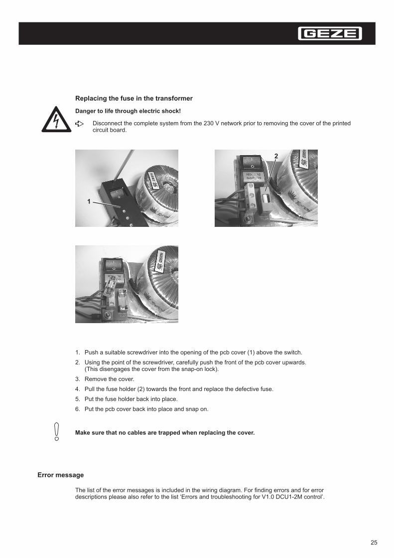
Replacing the fuse in the transformer
1. Push a suitable screwdriver into the opening of the pcb cover (1) above the switch.
2. Using the point of the screwdriver, carefully push the front of the pcb cover upwards.(This disengages the cover from the snap-on lock).
3. Remove the cover.
4. Pull the fuse holder (2) towards the front and replace the defective fuse.
5. Put the fuse holder back into place.
6. Put the pcb cover back into place and snap on.
Disconnect the complete system from the 230 V network prior to removing the cover of the printedcircuit board.
Danger to life through electric shock!
Make sure that no cables are trapped when replacing the cover.
1
2
Error message
The list of the error messages is included in the wiring diagram. For finding errors and for errordescriptions please also refer to the list ‘Errors and troubleshooting for V1.0 DCU1-2M control’.
25
7 Index
A
B
C
D
E
F
G
H
Accumulator ...................................... 8,9,14,22
Buttonfit ....................................................... 13
Cableconnect .............................................. 14
Contact maker EXTERIOR (KA) ....... 7,15
Contact maker AUTHORISED (KB) .. 7,15
Contact maker INTERIOR (KI) .......... 7,15
Componentreplace ............................................... 24
Display programme switchfit ........................................................ 13
Door leaveshang in ............................................... 11align ................................................... 12
Door suspensionhang in .............................................. 11
Draugh-proof system ........................ 20
Drawings ........................................... 4
Driver ................................................. 11,12, 23
Error message ................................... 10
Faultelectrical ............................................ 24
mechanical ........................................ 23
Functional test (pre-assembly) .......... 8
Geared motortest ..................................................... 23
Height adjustment
I
K
L
M
P
R
S
T
Interlock ............................................. 20
Key-operated switchfit ....................................................... 14
Learning .............................................. 7, 14, 19
Locking device .................................. 13
Maintenance ...................................... 21
Motion detector INTERIORalign ................................................... 16
Profiles install .................................... 10
Roller carriage replace ...................... 24
Safety information ............................. 3
Service mechanical............................ 21
Service modeswitch off ........................................... 18operate .............................................. 18switch on ........................................... 18functions ............................................ 18
Stop buffer ......................................... 13
Switchfit ....................................................... 13
Tools .................................................. 4
Toothed beltcheck tension .................................... 21Track ................................................. 9, 22, 23
Transformerreplace fuse ...................................... 25
26
EG-KonformitätserklärungEC-Declaration of ConformityCE-Déclaration de conformité
Hersteller: GEZE GmbH(Manufacturer, Fabricant) Reinhold-Vöster-Str. 21 – 29
D-71229 Leonberg
Produktbezeichnung: automatische Schiebetürantriebe(Product identifier, (automatic sliding door drives,Désignation du produit) systèmes automatiques pour porte coulissante)
GEZE Slimdrive SC, GEZE Slimdrive SC-FR 2M
__________________________________________________________________________________________________
Erklärung (Declaration, Déclaration):Die genannten Antriebe sind in alleiniger Verantwortung des o.g. Herstellers entwickelt, kon-struiert und gefertigt in Übereinstimmung mit folgendenden Richtlinien und Normen.The above drives are under the sole responsibility of the above manufacturer developed,designed and manufactured in accordance with the following directives and standards.Les produits mentionnés sont développés, construits es fabriqués en propre responsabilitédu fabricant susnommé en respectant suivantes.
EU-Richtlinien (EU-Directives, Directives UE):
EMV-Richtlinie 89/336/EWG in der Fassung 93/31/EWG(EMV Directive, Directive CEM)Niederspannungsrichtlinie 73/23/EWG in der Fassung (93/68/EWG.(Low Voltage Directive in the version, Directive relative à la basse tension, version).
Europäische Normen (European Standards, normes européennes):
EN 55011EN 61000-6-2
EN 60335-1EN 60950
____ Leonberg, den 02. Februar 2004Hermann AlberGeschäftsführer
27

28

29
GEZE GmbHP..O. Box 136371226 LeonbergGermany
GEZE GmbHReinhold-Vöster-Str. 21-2971229 LeonbergGermanyTel. +49 (0)71 52-203-0Fax+49 (0)71 52-203-310
GEZE Branches
Germany
Asia
Germany
GEZE GmbHNiederlassung Nord/OstBühringstr.813086 Berlin (Weissensee)Tel. +49(0)30-47 89 90-0Fax. +49(0)30-47 89 90-17E-Mail: [email protected]
GEZE Asia Pacific Ltd.Unit 630, Level 6. Tower 2
138 Shatin Rural Committee RoadShatin, New TerritoriesHong KongTel. +852 (0) 23 75 73 82Fax
Grand Central Plaza
. +852 (0) 23 75 79 36E-Mail: [email protected]
Poland
Switzerland
Spain
Scandinavia
Sweden
Norway
Finland
GEZE Schweiz AGBodenackerstr. 794657 DullikenTel. +41 (0) 62-285 54 00Fax. +41 (0) 62-285 54 01E-Mail: [email protected]
GEZE Iberia S.R.L.Pol.Ind. El PlaC/Comerc, 2-22, Nave 1208980 Sant Feliu de Llobregat(Barcelona)Tel. +34 (0) 9 02 19 40 36Fax. +34 (0) 9 02 19 40 35E-Mail: [email protected]
GEZE Scandinavia ABMallslingan 10Box 706018711 TäbyTel. +46 (0) 8-732 34-00Fax. +46 (0) 8-732 34-99E-Mail: [email protected]
GEZE FinlandBranch office of GEZE Scandinavia ABPostbox 2015871 HollolaTel. +358 (0) 10-400 5100Fax. +358 (0) 10-400 5120E-Mail: [email protected]
GEZE Scandinavia AB avd. NorgePostboks 632081 EidsvollTel. +47 (0) 639 572 00Fax. +47 (0) 639 571 73E-Mail: [email protected]
GEZE Polska Sp. z o.o.
ul.Annopol 3 (03-236 WarszawaTel. +48 (0) 22 814 22 11Fax
Żerań Park)
. +48 (0) 22 614 25 40E-Mail: [email protected]
GEZE Industries(Tianjin) Co., Ltd.Shuangchenzhong RoadBeichen Economic DevelopmentArea (BEDA)Tianjin 300400, P.R. ChinaTel. +86 (0) 22-26 97 39 95-0Fax. +86 (0) 22-26 97 27 02E-Mail: [email protected]
GEZE Industries(Tianjin) Co., Ltd.Branch Office BeijingThe Grand Pacific BuildingB Tower Room 2018 A, Guanghua RoadChaoyang District100026 Beijing, P.R. ChinaTel. +86 (0) 10 65 81 57-32/-42/-43Fax. +86 (0) 10 65 81 57-33E-Mail: [email protected]
GEZE Asia Sales Ltd.No. 88-1-408, East RoadFree Trade Zone of Tianjin PortTianjin, P.R. ChinaTel. +86 (0) 22 26 97 39 95-0Fax. +86 (0) 22 26 97 27 02E-Mail: [email protected]
GEZE Industries(Tianjin) Co., Ltd.
,Branch Office GuangzhouRoom 1113 Jie Tai Plaza218-222 Zhong Shan Liu Road510180 P.R. ChinaTel. +86 20 81 32 07-02
Guangzhou,(0)
Fax. +86 (0) 20 81 32 07-05E-Mail: [email protected]
GEZE GmbHNiederlassung WestNordsternstraße 6545329 EssenTel. +49(0)201-830 82-0Fax. +49(0)201-830 82-20E-Mail: [email protected]
GEZE GmbHNiederlassung MitteAdenauerallee 261440 Oberursel (b. Frankfurt)Tel. +49(0)61 71-6 36 10-0Fax. +49(0)61 71-6 36 10-1E-Mail: [email protected]
GEZE GmbHNiederlassung SüdReinhold-Vöster-Straße 21-2971229 LeonbergTel. +49(0)7152-203-594Fax. +49(0)7152-203-438E-Mail: [email protected]
GEZE SonderkonstruktionenGmbHPlanken 197944 Boxberg-SchweigernTel. +49(0)7930-9 2 94-0Fax. +49(0)7930-9 2 94-10E-Mail: [email protected]
GEZE SERVICE GmbHReinhold-Vöster-Str.2571229 LeonbergTel. +49(0)7152-92 33-0Fax. +49(0)7152-92 33-60E-Mail: [email protected]
GEZE SERVICE GmbHNiederlassung BerlinBühringstr.813086 Berlin (Weissensee)Tel. +49(0)30-47 02 17-30Fax. +49(0)30-47 02 17-33
GEZE Representative:
Id. No. 116719 Modification level 01 Drawing No. 70489-9-0976 • • Subject to change without notice• . Printed in Germany
Yourattentionisdrawntothe“productliabilitylaw“definedliabilitytothemanu-facturerforhisproductswhicharecon-tainedinthemaincatalogue(productinformation,usage,misuses,productactivity,productmaintenance,thedutytoinformandthedutytoinstruct).Noncompliancewiththeseconditionsre-lievesthemanufacturerfromanyliability.
Subsidiaries
GEZE Online:www.geze.com
DIN ISO 9001
Thehallmark
of ourenterprise
GEZE Industries(Tianjin) Co., Ltd.Branch Office ShanghaiDynasty Business CenterRoom 401-402No. 457 WuRuMuQi North Road200040 Shanghai, P.R. ChinaTel. +86 (0) 21 52 34 09-60/-61/-62Fax. +86 (0) 21 52 34 09-63E-Mail: [email protected]
Europe
France
Great Britain
Italy
Benelux
Middle East
GEZE France S.A.R.LZAC de l’Orme RondRN 1977170 ServonTel. +33 (0) 1 60 62 60 70Fax (0).+33 1 60 62 60 71E-Mail: [email protected]
Austria
GEZE Austria GmbHMayrwiesstraße 125300 Hallwang b. SalzburgTel. +43 (0) 662 66 31 42Fax. +43 (0) 662 66 31 42-15E-Mail: [email protected]
GEZE Italia SrlVia Giotto 420040 Cambiago (MI)Tel. +39 (0) 02 95 06 95-11Fax. +39 (0) 02 95 06 95-33E-Mail: [email protected]
GEZE Engineering Roma SrlVia Lucrezia Romana 9100178 RomaTel. +39 (0) 06 72 65 31 1Fax. +39 (0) 06 72 65 31 36E-Mail: [email protected]
GEZE Benelux B.V.Industrieterrein KapelbeemdLeemkuil 15626 EA EindhovenTel. +31 (0) 40 26 29 08 0Fax. +31 (0) 40 26 29 08 5E-Mail: [email protected]
GEZE Engineering Bari SrlVia Treviso 5870022 Altamura (Bari)Tel. +39 (0) 080 31 15 21 9Fax. +39 (0) 080 31 64 56 1E-Mail: [email protected]
U.A.E.GEZE Middle EastP.O. Box 17903Jebel Ali Free ZoneDubai.Tel. +971 (0) 4 88 33 112Fax. +971 (0) 4 88 33 240E-Mail: [email protected]
GEZE UK Ltd.Blenheim WayFradley ParkLichfieldStaffordshire WS13 8SYTel. +44 (0) 15 43 44 30 00Fax. +44 (0) 15 43-44 30 01E-Mail: [email protected]
Denmark
GEZE DenmarkBranch office of GEZE Scandinavia ABMøllehusene 3, 3.th.4000 RoskildeTel. +45 (0) 46-32 33 24Fax. +45 (0) 46-32 33 26E-Mail: [email protected]