Embed Size (px)
Citation preview
GB
Slimdrive SLV
Slimdrive SLV-FR 2M
Mat. No. 110257
D Mat.- Nr. 109638
Valid as of software version DCU1 V1.0
Assembly and service instructions
GB
Slimdrive SLV
Slimdrive SLV-FR 2M
Mat. No. 110257
D Mat.- Nr. 109638
Valid as of software version DCU1 V1.0
Assembly and service instructions
GB
Slimdrive SLV
Slimdrive SLV-FR 2M
Mat. No. 110257
D Mat.- Nr. 109638
Valid as of software version DCU1 V1.0
Assembly and service instructions
GB
Slimdrive SLV
Slimdrive SLV-FR 2M
Mat. No. 110257
D Mat.- Nr. 109638
Valid as of software version DCU1 V1.0
Assembly and service instructions
GB
Slimdrive SLV
Slimdrive SLV-FR 2M
Mat. No. 110257
D Mat.- Nr. 109638
Valid as of software version DCU1 V1.0
Assembly and service instructions
GB
Slimdrive SLV
Slimdrive SLV-FR 2M
Mat. No. 110257
D Mat.- Nr. 109638
Valid as of software version DCU1 V1.0
Assembly and service instructions
GB
Slimdrive SLV
Slimdrive SLV-FR 2M
Mat. No. 110257
D Mat.- Nr. 109638
Valid as of software version DCU1 V1.0
Assembly and service instructions

1 Inhalt
1 Safety Remarks 42 Overview 52.1 Diagrams 52.2 Tool 62.3 Torques 62.4 Components and Modules 72.5 Functional test 9
3 Assembly 113.1 Preparations to be made by the customer 113.2 Installation 113.3 Start-up 163.4 Dismantling 19
4 Service mode 204.1 Operation 204.2 Learning 214.3 Air lock or vestibule 22
5 Service and maintenance 235.1 Mechanical service 235.2 Maintenance 25
6 Fault elimination 266.1 Mechanical faults 266.2 Electrical faults 27
7 Index 29
Statement from the manufacturer 30
2
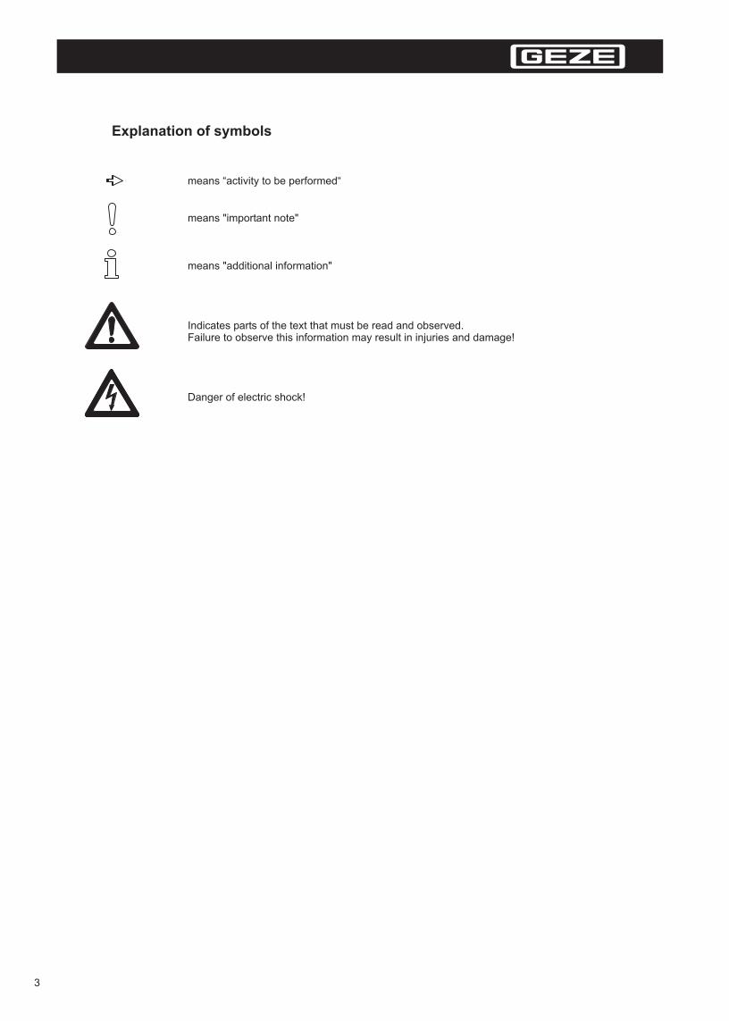
Explanation of symbols
means “activity to be performed“
means "important note"
means "additional information"
Indicates parts of the text that must be read and observed.Failure to observe this information may result in injuries and damage!
Danger of electric shock!
3

1 Safety remarks
Intended use
The Slimdrive SLV and Slimdrive SLV-FR 2M are solely suitable for use - in dry rooms- in automatic door systems for horizontally moved door leaves- in entrances and interior areas of pedestrian traffic in commercial plants and public areas
The Slimdrive SLV and Slimdrive SLV-FR 2M may not be used as a fire or smoke protection door.
The Slimdrive SLV-FR 2 M is approved for use in escape and rescue routes.The Slimdrive SLV may not be used as an escape and rescue door.
Safety remarks
- The prescribed installation, maintenance and repair work must be performed by properly trained personnel authorised by GEZE.
- For technical checks pertaining to security, the country-specific rules and regulations must be observed.- GEZE shall not be liable for injuries or damage resulting from unauthorised modification of the
equipment, and the approval for use in escape and rescue routes is voided when unauthorised changes are made (for Slimdrive SLV-FR 2M).
- When combining with outside products, GEZE will not assume any guarantee.Only use GEZE original parts for repair and maintenance works as well.
- The connection to the power supply must be made by a qualified electrician. Implement mains supply and earthed wire check according to VDE 0100 part 610
- Use a customer-accessible 10-A overload cut-out as the line-side disconnecting device.- Protect the display program switch from unauthorized access.- The detection field of the motion detector in direction of emergency exit must satisfy AutSchR.- In accordance with Machine Directive 98/37/EC,
door system identified in accordance with CE Identification Directive 93/68/EEC beforethe door system.
- Observe the latest status of guidelines, standards and countryspecific rules,especially:- ZH 1/494 "Guidelines for power operated windows, doors and gates"- VDE 0100, Part 610, "Setting up heavy-current installations with nominal voltages up to 1000 V"
- AutSchR "Directive for automatic windows, doors and gates" (for Slimdrive SLV-FR 2M).- Accident prevention rules, especially BGV A1 “General Rules”and BGV A2
.
a danger analysis must be performed and the commissioning
- DIN EN 60335-2-103 "Safety electronic devices for home use and similar purposes; special requirements for drives, for gates, doors, and windows"
“Electrical systems and resources”
Safety-conscious work
- Secure workplace against unauthorised entry.
- Watch swinging area of long system parts.
- Never carry out work with a high safety risk (e.g. installing the drive, hood or door leaf) while alone.
- Secure hood/drive shrouding against falling.
- Use only the cables indicated in the cable position plan. Put up screens according to the connection diagram.
- Secure loose internal drive cables with binders.
- Before working on the electrical system:- Disconnect the drive from the 230 V mains network and check to ensure that it is not supplied with
power.- Disconnect the control from the 24 V accumulator.- When using an uninterrupted power supply (UPS), the system is live even if the line is isolated.
- Always use insulated wire-end ferrules for wire cores.
- Place safety stickers on the glass leaf doors (mat. no. 081476).
- Danger of injury by opened drive. Hair, clothing, cables etc. can be pulled in by rotating parts!
- Danger of injury by unsecured pinching, impact, drawing-in or shearing spots!
- Danger of injury by broken glass!
- Danger of injury by sharp edges in the drive!
- Danger of injury during installation by freely moving parts!
4
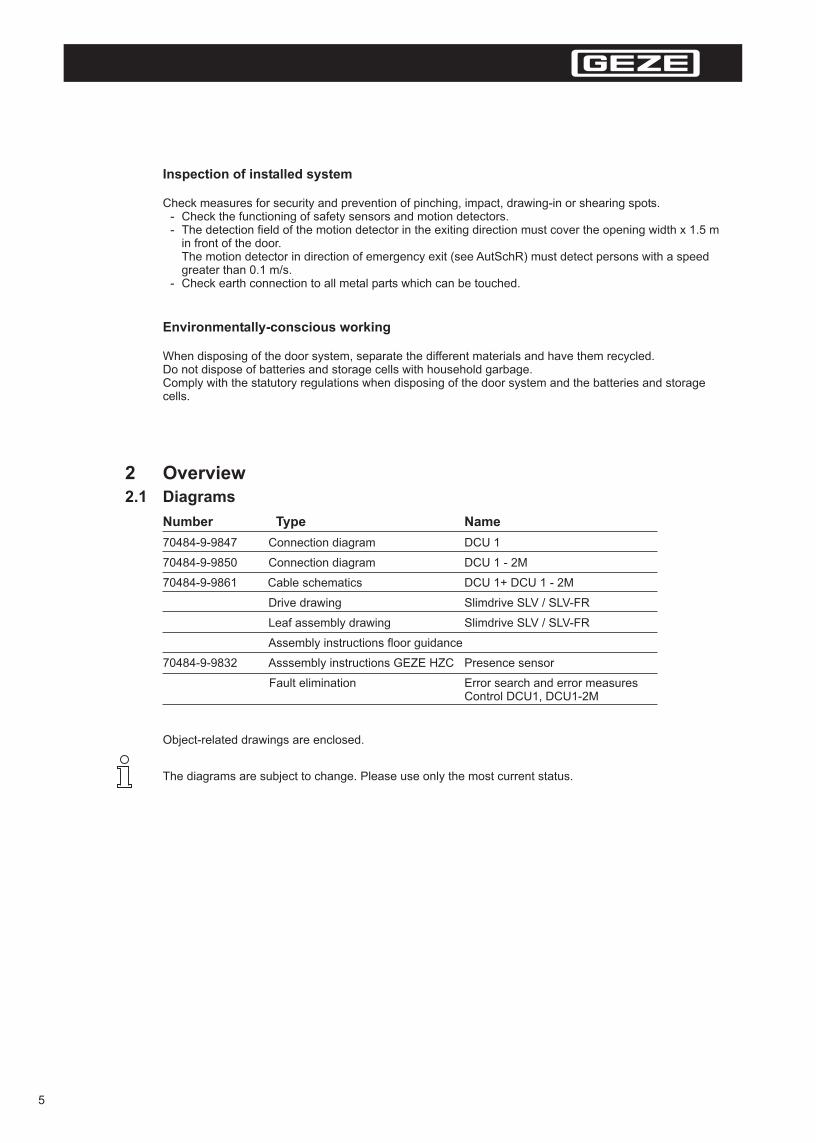
Inspection of installed system
Check measures for security and prevention of pinching, impact, drawing-in or shearing spots.- Check the functioning of safety sensors and motion detectors.- The detection field of the motion detector in the exiting direction must cover the opening width x 1.5 m
in front of the door.The motion detector in direction of emergency exit (see AutSchR) must detect persons with a speed greater than 0.1 m/s.
- Check earth connection to all metal parts which can be touched.
Environmentally-conscious working
When disposing of the door system, separate the different materials and have them recycled.Do not dispose of batteries and storage cells with household garbage.Comply with the statutory regulations when disposing of the door system and the batteries and storage cells.
The diagrams are subject to change. Please use only the most current status.
2 Overview2.1 Diagrams
Number Type Name
70484-9-9847 Connection diagram DCU 1
70484-9-9850 Connection diagram DCU 1 - 2M
70484-9-9861 Cable schematics DCU 1+ DCU 1 - 2M
Drive drawing Slimdrive SLV / SLV-FR
Leaf assembly drawing Slimdrive SLV / SLV-FR
Assembly instructions floor guidance
70484-9-9832 Asssembly instructions GEZE HZC Presence sensor
Fault elimination Error search and error measures Control DCU1, DCU1-2M
5
Object-related drawings are enclosed.

Tool Size
Measuring tape
Marking pen
Torque spanner
Allen key 2 mm, 2.5 mm, 3 mm, 5 mm, 6 mm
Open ended spanners 8 mm, 10 mm, 13 mm
Screwdriver set up to 6 mm
Pin punch 3 mm with point length = 60 mm
Side cutting pliers
Crimping tool for electrical cable
Wire stripper
Multimeter
2.2 Tool
2.3 Torques
see drive drawing
6
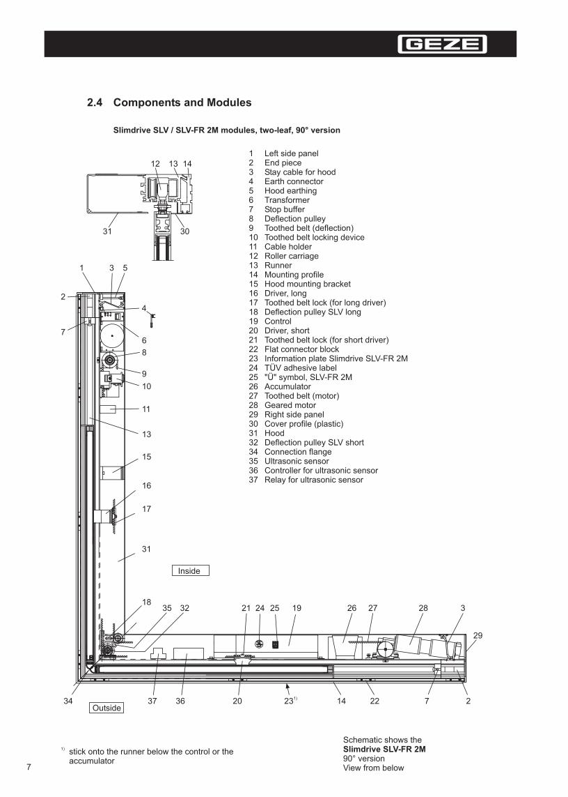
2.4 Components and Modules
Slimdrive SLV / SLV-FR 2M modules, two-leaf, 90° version
1) stick onto the runner below the control or the accumulator
1
7
2
3 5
4
6
8
9
10
11
15
13
16
17
31
1821 24 25 19 26 27 28
29
2722141)232034 3637
33235
Inside
Outside
Schematic shows the Slimdrive SLV-FR 2M90° versionView from below
1 Left side panel2 End piece3 Stay cable for hood4 Earth connector5 Hood earthing6 Transformer7 Stop buffer8 Deflection pulley9 Toothed belt (deflection)10 Toothed belt locking device11 Cable holder12 Roller carriage13 Runner14 Mounting profile15 Hood mounting bracket16 Driver, long17 Toothed belt lock (for long driver)18 Deflection pulley SLV long19 Control20 Driver, short21 Toothed belt lock (for short driver)22 Flat connector block23 Information plate Slimdrive SLV-FR 2M24 TÜV adhesive label25 "Ü" symbol, SLV-FR 2M26 Accumulator27 Toothed belt (motor)28 Geared motor29 Right side panel30 Cover profile (plastic)31 Hood32 Deflection pulley SLV short34 Connection flange35 Ultrasonic sensor36 Controller for ultrasonic sensor37 Relay for ultrasonic sensor
12 13 14
31 30
7

Slimdrive SLV / SLV-FR 2M modules, two-leaf, 270° version
Outside
Inside
Schematic shows theSlimdrive SLV-FR 2M270° versionView from below
1) stick onto the runner below the control or the accumulator
1
2
3 5
4
6
8
9
10
11
31
15
16
17
33
33 3536 3721242519262728
29
2 22 13 13 20 34
3 1)23
12 13 14
31 301 Right side panel2 End piece3 Stay cable for hood4 Earth connector5 Hood earthing6 Transformer7 Stop buffer8 Deflection pulley9 Toothed belt (deflection)10 Toothed belt locking device11 Cable holder12 Roller carriage13 Runner14 Mounting profile15 Hood mounting bracket16 Driver, long17 Toothed belt lock (for long driver)19 Control20 Driver, short21 Toothed belt lock (for short driver)22 Flat connector block23 Information plate Slimdrive SLV-FR 2M24 TÜV adhesive label25 "Ü" symbol, SLV-FR 2M26 Accumulator27 Toothed belt (motor)28 Geared motor29 Left side panel30 Cover profile (plastic)31 Hood33 Deflection pulley SLV double34 Connection flange35 Ultrasonic sensor36 Controller for ultrasonic sensor37 Relay for ultrasonic sensor
8
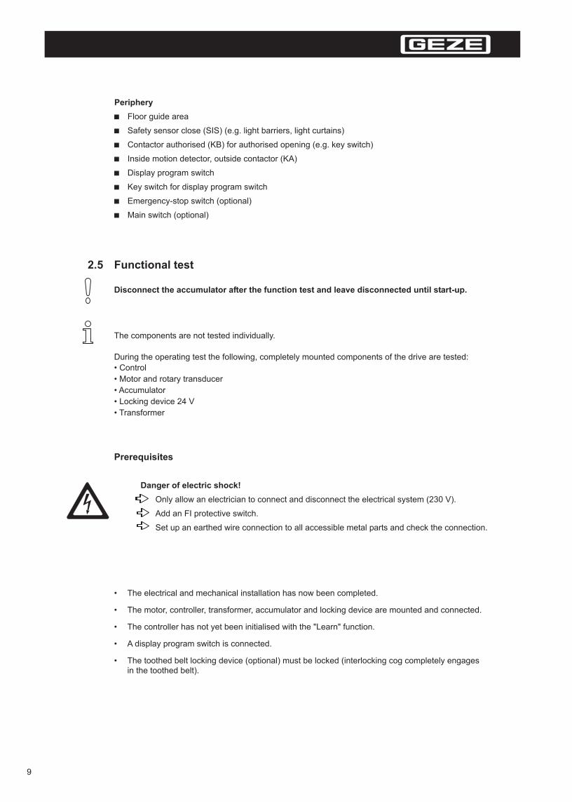
Periphery
Floor guide area
Safety sensor close (SIS) (e.g. light barriers, light curtains)
Contactor authorised (KB) for authorised opening (e.g. key switch)
Inside motion detector, outside contactor (KA)
Display program switch
Key switch for display program switch
Emergency-stop switch (optional)
Main switch (optional)
2.5 Functional test
During the operating test the following, completely mounted components of the drive are tested:
• Control
• Motor and rotary transducer
• Accumulator
• Locking device 24 V
• Transformer
The components are not tested individually.
Disconnect the accumulator after the function test and leave disconnected until start-up.
• The electrical and mechanical installation has now been completed.
• The motor, controller, transformer, accumulator and locking device are mounted and connected.
• The controller has not yet been initialised with the "Learn" function.
• A display program switch is connected.
• The toothed belt locking device (optional) must be locked (interlocking cog completely engagesin the toothed belt).
Prerequisites
Danger of electric shock!
Only allow an electrician to connect and disconnect the electrical system (230 V).
Add an FI protective switch.
Set up an earthed wire connection to all accessible metal parts and check the connection.
9
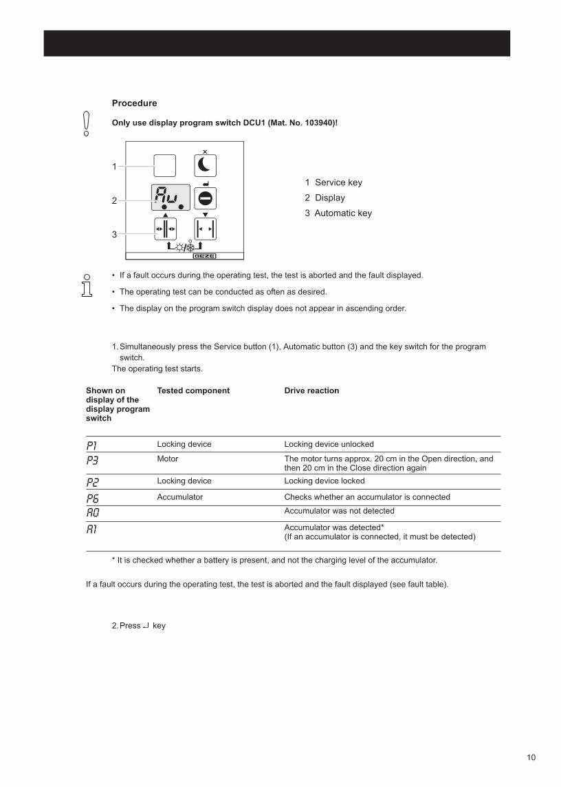
1
2
3
1 Service key
2 Display
3 Automatic key
• If a fault occurs during the operating test, the test is aborted and the fault displayed.
• The operating test can be conducted as often as desired.
• The display on the program switch display does not appear in ascending order.
1.Simultaneously press the Service button (1), Automatic button (3) and the key switch for the program
switch.
The operating test starts.
Procedure
Only use display program switch DCU1 (Mat. No. 103940)!
* It is checked whether a battery is present, and not the charging level of the accumulator.
If a fault occurs during the operating test, the test is aborted and the fault displayed (see fault table).
Shown on display of the display program switch
Tested component Drive reaction
Locking device unlocked
The motor turns approx. 20 cm in the Open direction, and then 20 cm in the Close direction again
Locking device locked
Checks whether an accumulator is connected
Accumulator was not detected
Accumulator was detected*(If an accumulator is connected, it must be detected)
P1P3
P2
P6A0
A1
Locking device
Locking device
Accumulator
2.Press key
Motor
10
3 Assembly
3.1 Preparations to be made by the customer
3.2 Installation
Installing profiles
Check the preparations made by the customer to ensure proper installation:
• Type and loading capacity of the facade construction or
• Sub-construction - Levelness of the installation surface
• Requirements of interconnection diagram
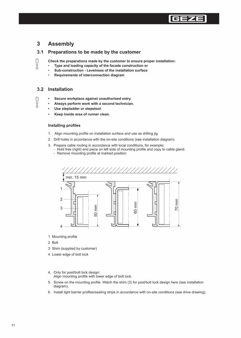
1. Align mounting profile on installation surface and use as drilling jig.
2. Drill holes in accordance with the on-site conditions (see installation diagram).
3. Prepare cable routing in accordance with local conditions, for example:- Hold free (right) end piece on left side of mounting profile and copy to cable gland.- Remove mounting profile at marked position.
4. Only for post/bolt lock design:Align mounting profile with lower edge of bolt lock.
5. Screw on the mounting profile. Watch the shim (3) for post/bolt lock design here (see installationdiagram).
6. Install light barrier profiles/sealing strips in accordance with on-site conditions (see drive drawing).
min. 15 mm
50
mm
60
mm
70
mm
1
2
3
4
1 Mounting profile
2 Bolt
3 Shim (supplied by customer)
4 Lower edge of bolt lock
• Secure workplace against unauthorised entry.
• Keep inside area of runner clean.
• Always perform work with a second technician.
• Use stepladder or stepstool.
11
1
7. Press sealing rubber into sealing strips.
8. Lay outside drive sensor cable:Pre-drill mounting profile in suitable position and pull in cables (see block diagram).
9 Connect runners with the pre-assembled modules with the connection flange
10. Insert runners with pre-assembled modules into the mounting profiles.If necessary, loosen the headless set screws of the connection flange again
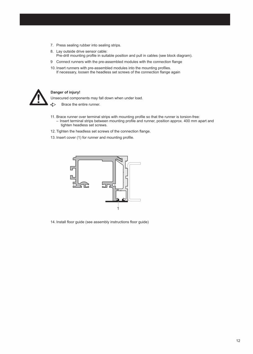
11. Brace runner over terminal strips with mounting profile so that the runner is torsion-free:– Insert terminal strips between mounting profile and runner, position approx. 400 mm apart and
tighten headless set screws.
12. Tighten the headless set screws of the connection flange.
13. Insert cover (1) for runner and mounting profile.
14. Install floor guide (see assembly instructions floor guide)
Brace the entire runner.
Danger of injury!
Unsecured components may fall down when under load.
12
Installing door leaves
Always install door leaves together with another person.
Danger of injury by broken glass!
• In order to install the door leaves to drive, the door suspensions must be installed at the door leaves.
• The door suspensions must be installed when the windows are mounted in the door leaves.In case oflater installation of door suspension, the frames of the door leaf must be removed (see assemblyinstructions door leaf).
The door leaves are still unsecured and slide easily.
Ensure that the door leaves are not moved accidentally or by unauthorised persons!
Danger of crushing!
1. Remove roller carriage from transport lock.
2. Hook door leaf into roller carriage:Install the door suspensions from the front into the suspension bolts of two roller carriages.
3. Secure door leaves via lock nuts.
Adjusting the door leaves
1. Set parallel position and height of door leaves at hexagon of suspension bolts:– Ensure smooth movement of door leaves individually– Align door leaves flush. Ensure same height and parallel closing edges when doing so.– Lock door leaves with hexagon nut.
2. Adjust stop buffers for the door leafs.
Install height adjustment
1. Slide brush into height-adjustment strip (see overview diagram).
2. Push height-adjustment strip into door leaf (see drive drawing).
3. Install floor guide (see drive drawing).
4. Ensure that the door leaves are moving smoothly.
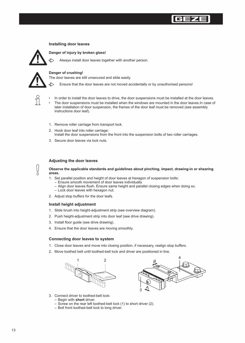
Connecting door leaves to system
3. Connect driver to toothed-belt lock:– Begin with short driver.– Screw on the rear left toothed-belt lock (1) to short driver (2).– Bolt front toothed-belt lock to long driver.
1. Close door leaves and move into closing position, if necessary, realign stop buffers.
2. Move toothed belt until toothed-belt lock and driver are positioned in line.
Observe the applicable standards and guidelines about pinching, impact, drawing-in or shearing areas.
3
4
A
B1 2
13

3
4
~ 0.5 mm
8. Loosen locking bolts (4).
9. Set belt guide (3) on the lock side so that a gap of approx. 0.5 mm exists between the belt guide andthe toothed belt.
10. Tighten locking bolts (4) again.
The driver may not contact the lock during operation!
12
Positioning toothed belt locking device
1. Close the door leaves.
2. Loosen the screws (1) and (2) on the locking device.
3. Align the locking device to the toothed belt.After installation the locking pin must be positioned above the hole in the hood so that it can be lockedand released.If necessary, enlargen holes.
4. Tighten bolts (1).
5. Align locking device guide so that it has sufficient clearance on both sides.
6. Tighten bolts (2).
7. Lightly lubricate sliding surfaces (see arrows in figure shown above).
– Continue with long driver – Screw on the front right toothed-belt lock (3) to long driver (4).– Adapt the position of the toothed-belt lock to the toothed belt using the lock teeth .– Screw on front toothed-belt lock to long driver and make fine adjustments to toothed-belt
(lock teeth ).
The door leaves are joined with the system and the position of the main closing edge is set.
B
A
14

Installing switch/button
For electrical installation, see terminal connection diagram
Mounting key switch
The display program switch can be locked and unlocked by using the key switch
For electrical installation, see terminal connection diagram
The key switch for the Slimdrive SLV-FR 2M is mandatory!
The key switch for the Slimdrive SLV can be installed as an option.
For electrical installation, see terminal connection diagram
Mounting display program switch
Only use display program switches DCU (Mat. No. 103940)!
Installing safety equipment
Mounting motion detector
For electrical installation, see terminal connection diagram
15
3.3 Start-up
Connecting cable
1. Disconnect the system from the 230 V mains network.
2. Carry out cable routing in an orderly manner in accordance with terminal connection diagram:Use cable take-up in the end pieces and cable holders. Cut out breaks in the side panel if necessary.
3. Make connections to the controls according to the connection diagram.
4. Remove cables from sliding path of leaves and driver before startup and secure with cable ties.
• If flexible cables are used, attach insulated wire-end ferrules.
• The accumulator must be completed charged.
Starting Learn function
1. Insert the display program switch in the controller.
2. Clear out detection field of all sensors.
3. Connect system to 230 V mains network.The controller jumps to the Learn function with initial start-up (see Chapter 4.2) and the displayprogram switch shows LE. Next, is displayed for a controller DCU1 ( = standard door) or fora controller DCU1-2M ( = escape door), and a version number, e.g. 14 for version 1, revision 4.
If the controller was already in operation, Learning mode is started by selecting LE in the Service menu,Chapter 4.2.
4. Close the door leaves.
5. Press key:– Door leaves open and close again.– Run parameters are determined and saved.
Learn program proceeds as described in Chapter 4.2.
Door leaves move, all the locking devices on the door are deactivated.
Move away from the door path.
Danger of crushing!
Hair, clothing, cables etc. can be pulled in by rotating parts!
When working on open drive, be cautious of rotating parts.
Danger of injury by opened drive!
To perform the Learn function correctly, the door leaves must be closed.
Danger of electric shock!
Only allow an electrician to connect and disconnect the electrical system (230 V).
Implement mains supply and earthed wire check according to VDE 0100 part 610.
16

Check the function
1. Switch system off.
2. Switch system on again.
3. Set display program switch to automatic:The self-test will run automatically.
4. Check function of modules and periphery:
– Safety sensor close (SIS):When light barrier/light curtain is interrupted, door may not close following actuation.Door closes slowly after 4 minutes, with fault message.
– Safety sensor open (SIO):e.g. test fixed-field sensor operation and actuation area.
– Inside contactor (KI)
– Contact maker Justified (KB)
– Outside contactor (KA)
– Use the Diagnosis function (Chapter 4.1) in the Service mode to check whether the controller haslearned all the connected modules/safety devices.
– Check locking function and reset locking position if necessary (Chapter 3.2).
5. If the system does not function, check the power supply.See also fault table as well as “Errors and Measures” document.
6. If program selector indicates l6, manually push door leaves to reduced opening width with and press key twice.
– Door leaves open and close.
When the program selector shows LE or Au, the Learn program has been completed and the door is ready for operation.
For Slimdrive SLV-FR 2M the reduced opening width is only permissible if the reduced opening width is greater than the required escape route width (see Chapter 4.2).
17

Adjusting inside motion detectors
Slimdrive SLV-FR 2M:
Slimdrive SLV
• Inside motion detectors have to detect movements in the direction of escape as of a speed of 0.1 m/s at a distance of at least 1500mm from the door (AutSchR)
• To cover the prescribed detection area, two self-monitoring inside motion detectors, depending on thetype, may be required for large opening widths.For notes on how to connect the two motion detectors in the direction of escape, see connectiondiagram.
• When adjusting the motion detector ensure that the complete opening area is detected (see drawing).Adjust the sensitivity of the sensor and the detection field accordingly.
• The motion detector(s) should be set so that the detection field covers the entire door opening widthand up to 1.5 m in front of the door. We recommend that you install two motion detectors for dooropening widths greater than 80 in (2 m).
• Inside motion detectors have to detect movements from a speed of 0.1 m/s on.
After setting the motion detector(s), check the detection field on the ground.
18
OW
> 1
50
0 m
m
10
mm
>5
0
OW
> 1
50
0 m
m
> 1
m
500 m
Mounting of hood
Two people should always mount the hood.
Filling out user manual
Record installed features in the user manual for the owner.
Danger of injury from swivelling hood!
1. Installing cables for hood stay cable at the mounting elements of the runner (see Chapter 3.17).
2. Insert cable for hood earth at the earth connector on the runner.
3. Clean hood at the contact points for hood mounting brackets. When doing so, ensure that the hood isnot lubricated at the contact points.
4. Pull the protective film off the Velcro strip on the hood mounting bracket.
5. Slide hood onto side panels until it engages and press it firmly near the hood mounting brackets.
6. Screw in locking pin (for units with a lock).
The lock may not scrape the hood.
The cables may not be clamped.
3.4 Dismantling
Two people are required to remove the hood and lower it carefully at the hood stay cable.
Danger of injury from falling hood!
Hood is held by an engaging mechanism and the Velcro strips of the hood mounting bracket.
Secure door leaves against accidental movement.
Disconnect the accumulator.
Danger of injury due to impact and crushing!
Disconnect the system from the 230 V mains network before working on the electrical system.
Danger of electric shock!
Removal is carried out in the reverse order of installation.
Pull out the height adjustment strip before unhinging the door leaf.
Do not rest the door leaves on the height adjustment strip.
Risk of injury from height adjustment strip!
19

4 Service mode
4.1 Operation
The Service mode consists of four menus which are divided into individual functions.Different settings are possible within the functions.
The door leaves open and close after each change.
IIn the Service mode the door maintains the current operating state and opens and closes accordingly.
Exception: Settings and .
The keys of the display program switch are assigned as follows in the Service mode:
For the list of menu functions, see terminal connection diagram.
Access to Service mode:
• Only with display program switch (Mat. No. 103940)
• Not in the Night operating mode
• Operation only possible with the key switch actuated (DCU1-2M)
• It is not possible to operate the display program switch during the self-test
The Service mode starts with the first function in the first menu (function ).
Switching Service mode on/off
Operating Service mode
If no key is pressed for a period of 5 minutes, then the controller returns to the normal operating mode.
Exceptions: in the Learning mode, in the Diagnostic mode and with motor isolated.
Press the service key (1) and the "closing time" key at the same time.
Button Description
Go to previous function/setting or increase value
Go to next function/setting or decrease value
Confirm function and switch to the settings/Accept setting and returnto the current menu
X Cancel and return to first menu ( function)
1
6
2
34
5
1 Service key
2 Display
3 Zero position unknown(Door not yet initialized completely.Not an error)
4 Maintenance indicator
5 LED for reduced opening width
6 "Closing time" key
20

The door calculates its running parameters by using the Learn function in the Service mode.
The display program switch displays the following steps:
Close door leaves before learning.
To learn a reduced opening size, the operator must submit the escape route width specified for the escape route in writing.Only when this document has been submitted is it permitted to learn a reduced opening width. The set reduced opening width must be at least as large as the specified escape route width. A copy of the document must be included with the service or test log..
The reduced opening width may not be smaller than 30% of the opening width. The control will not learn a smaller reduced position.
Learning a reduced position for escape doors (DCU1-2M)
A reduced opening width can also be learned in the context of the Learn program.
1. Before starting the learn program, install a jumper on the control between terminals 2 and 6.Begin learning.
2. When is displayed at the display program switch, move the door until the desired position for thereduced opening width is reached.
3. Press buttonDoor position is accepted.
4. Press buttonThe Learn program is ended.
5. Remove the jumper between terminal 2 and 6 again.
4.2 Learning
Display
LOL1L3L2L8L4L6
L7EL
Description
Start
Checking the rotary transducer
Opening width
Toothed belt locking device
Friction
Door leaf mass
Reduced opening width
End
Error in learning (see Chapter 6.2)
Possible settings
—
—
—
—
—
—
Position the door in the desired position.
Press button:The setting is adopted.
- or -
Automatic acceptance after 30 seconds:
Adopt setting
21
4.3 Air lock or vestibule using one program selector (only for DCU1)
Air lock: Two sliding doors use the same program selector.One door will only open if the other is closed.
Vestibule: Two sliding doors use the same program switch.
The air lock or vestibule functions are only available for standard sliding doors (DCU1).
1. Start up the inner door (main control) as with a single system.During this the outside door (secondary control) is de-energised.
2. Switch off the inside door.
3. Start up the outside door as with a single system. During this the inside door is de-energised.
4. For the outside door, set value of
for secondary control (air lock) or
for secondary control (vestibule) in menu item .
5. Check whether the value is switched on for inner door in the menu item .
6. Switch off the system and start both systems simultaneously.
• Only connect the power supply of the program selector display to the internal doorduring operation of both systems.
• Supply the display program switch with the power of the outer door during outer door start-up.
Starting up an air lock or vestibule system:
For the air lock and vestibule, the program selector only displays the error reports of the main control.
Cancelling Learning mode
Check:
1. Switch over to the "Automatic" program.
2. Move door into “Winter” operational mode by simultaneously pressing the keys and .
3. Check position of reduced opening width with a tape measure by actuation or with“reduced continuous open".
Press the service key and the closing time key at the same time.
These functions are not permissible for sliding doors in escape routes (DCU1-2M).
22
5 Service and maintenance
5.1 Mechanical service
Always attach the hood with two persons, that is, always remove the hood with two persons.
When removing, carefully lower hood at the hood stay cable.
Make certain the hood engages when it is attached and press the velcro strips firmly into place.
Danger of injury from falling hood!
Hood is held by an engaging mechanism and the Velcro strips of the hood mounting bracket.
Secure door leaves against accidental movement.
Disconnect the accumulator.
Danger of crushing!
Disconnect the system from the 230 V mains network before working on the electrical system.
Danger of electric shock!
When working on open drive, be cautious of rotating parts.
Danger of injury by opened drive!
Hair, clothing, cables etc. can be pulled in by rotating parts!
• Keep inside area of runner clean.
• Three teeth of toothed belt must engage on each side of toothed belt lock.
23

5 4 32 mm
2 1
Avoid unnecessarily high toothed belt tension.
1. Loosen bolts (2).
2. Pull motor (1) with mounted toothed belt (5) to the right.
3. Tighten bolts (2).
4. Loosen bolt (4).
5. Push sliding block (3) toward motor (arrow). When doing so, leave a gap of approx. 2 mm betweensliding block and motor.
6. Tighten bolt (4).
7. Insert a large flat-head screwdriver into the gap between the sliding block and motor and loosenbolts (2).
8. Lever motor to the right with the screwdriver to tension the toothed belt (5) (displacement force Fat motor is approx. 300 N).
9. Tighten bolts (2) again.
Tensioning toothed belt
Checking toothed belt tension
1. Start up door.Toothed belt may not lift up from the motor gear or skip when braking toward the open position.
2. If the toothed belt lifts up or skips, increase toothed belt tension:– Mark motor position at the runner.– Move motor to the right in 1-mm increments.
24

1. Keep the test documents up-to-date and make them available.
2. In the menu item of the second Service menu, bring up the number of openings ( ), the operating
hours ( ) and the number of self-tests ( ) and record these in the maintenance log.
5.2 Maintenance
The prescribed maintenance work on Slimdrive SLV and Slimdrive SLV-FR 2M is to be carried out by properly trained personnel at least once a year or when the service display on the program selector display lights up (see figure below).
After completing the maintenance work always carry out the Learn function for the door(see Chapter 4.2).
Test object
Runner
Roller carriage
Floor guide area
Floor routing section (brushes)
Door leaf
Toothed belt
Locking system
Accumulator
Screws
Modules and periphery
Cable
Action
Check for cleanliness
Check the wear of the rollers
Check for smooth function
Check for soiling and hardness
Check for smooth movement
Check for wear and damageCheck tension
Check at the locking device for damage
Check for function
Check accumulator voltage
Check for tight fit
Check for correct operation
Check for damage and proper fastening
Remarks
Clean the runner, if necessary
Remove the wear, if necessary
Clean the floor routing section, if necessary
Clean or replace, if necessary
See Chapter 7.1
Replace toothed belt if necessaryTighten the toothed belt, if necessary (see Chapter 5.1)Replace toothed belt if necessary
Re-position the locking device, if necessary (see Chapter 3.2)
Replace accumulator, if necessary
Tighten the bolts, if necessary(for torques refer to drive drawing)
Replace the module, if necessary(see Chapter 6.1)
If necessary, fasten cable or replace it
25
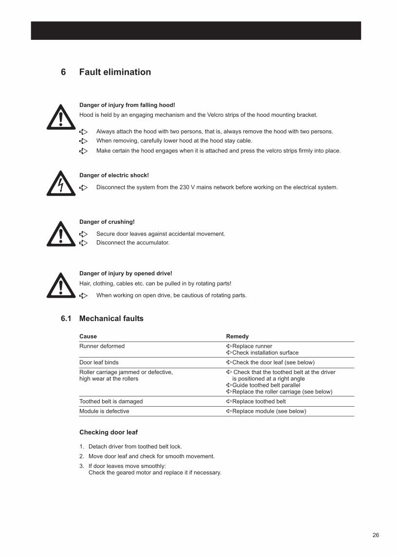
6 Fault elimination
6.1 Mechanical faults
Checking door leaf
1. Detach driver from toothed belt lock.
2. Move door leaf and check for smooth movement.
3. If door leaves move smoothly:Check the geared motor and replace it if necessary.
Cause Remedy
Runner deformed Replace runner Check installation surface
Door leaf binds Check the door leaf (see below)
Roller carriage jammed or defective, Check that the toothed belt at the driverhigh wear at the rollers is positioned at a right angle
Guide toothed belt parallel Replace the roller carriage (see below)
Toothed belt is damaged Replace toothed belt
Module is defective Replace module (see below)
Always attach the hood with two persons, that is, always remove the hood with two persons.
When removing, carefully lower hood at the hood stay cable.
Make certain the hood engages when it is attached and press the velcro strips firmly into place.
Danger of injury from falling hood!
Hood is held by an engaging mechanism and the Velcro strips of the hood mounting bracket.
Disconnect the system from the 230 V mains network before working on the electrical system.
Danger of electric shock!
Secure door leaves against accidental movement.
Disconnect the accumulator.
Danger of crushing!
When working on open drive, be cautious of rotating parts.
Danger of injury by opened drive!
Hair, clothing, cables etc. can be pulled in by rotating parts!
26

Replace roller carriage
Replacing module
1. Detach driver from toothed belt lock.
2. Loosen lock nut on suspension bolt of roller carriages.
3. Remove door leaf.
4. Loosen and remove terminal strip on end piece.
5. Take out end piece upward.
6. Remove buffer from runner.
7. Replace the roller carriage.
8. Install roller carriage in reverse order. For torques, see overview diagram.
1. Fastening with sliding block and slot entry:Loosen the screw on the sliding block and move the sliding block sideways.
2. Fastening with sliding block and hole:Loosen and remove the fastening bolts.
3. Remove and replace the module.
4. Fasten the module in reverse order.
Current pending error reports are briefly displayed cyclically (10 s) in operation at the display program switch. Additionally, they are entered in the error memories and .
If the dot lights up in the left half of the program display selector screen, then the installation was unable to completely initialize.
Either there is an obstruction or something in the installation itself has become jammed.
The dot disappears as soon as the door has been opened completely and closed again once.
For 2-leaf doors:To replace a roller carriage on the left (right) door leaf, remove the left (right) door leaf and the left (right) end piece.
For troubleshooting and elimination, see the fault table.
6.2 Electrical faults
If no errors are displayed during a malfunction, or if the display program switch has no function:
Check for active power supply
Check cable and cable connections
Check the fuses in the control and in the transformer and replace as necessary (see below)
For the list of error messages, see terminal connection diagram
Error reports
27

Replace fuse in transformer
1. Insert a suitable screwdriver in the opening of the board cover (1) above the switch.
2. Carefully push up the end wall of the board cover using the tip of the screwdriver(this releases the snap hinge).
3. Remove the cover.
4. Pull off the fuse holder (2) towards the front and replace the defective fuse.
5. Plug in the fuse holder.
6. Replace the board cover and snap into place.
Disconnect the system from the 230 V mains network before removing the board cover.
Danger of electric shock!
Cables must not be pinched when mounting the hood.
1
2
28

7 Index
AAccumulator 7, 8, 9
Air lock .......................................... 22
CCable
connecting ................................. 16
Contactor authorised (KB) ........... 9, 17
Contactor inside (KI) ......................17
Contactor, outside (KA) ................ 9, 17
Controllerconnect ...................................... 16
DDiagrams ....................................... 6
Display program switchmount ......................................... 15
Door leaveshook in ....................................... 13adjust ......................................... 13install height adjustment ............ 13check ......................................... 26connect to system ...................... 13
Door suspensionsinstall .......................................... 13
Driver ............................................ 13, 14
FFault messages ........................... 27
Faultselectrical .................................. 27mechanical .............................. 26
Functional test (Pre-installation) ......9
GGeared motor
check ......................................... 26
HHood
mounting .................................... 19dismantling ................................. 19
Hood earthinginsert ........................................... 19
Hood mounting bracketRemove the protective film...........19
K
Key switchmounting .....................................15
LLearning ........................................ 21
Light barrierprofiles installing ......................... 11
MMaintenance ................................. 23
Module replace ................................... 27
Motion detectors adjust inside ........................... 18
Mounting profile install ........................................ 11
align ......................................... 11
P
Profilesinstalling .................................... 11
RRoller carriage
replace ...................................... 27
Runnermount ......................................... 12
SSafety remarks .............................. 4
Self-test ..........................................17, 20, 25
Servicemechanical ................................. 23
Service modefunctions ..................................... 20switch off .................................... 20switch on .................................... 20operate ....................................... 20
Side panelcut out .........................................16
Stay cable for hood......................... 19
Stop buffers adjust ......................................... 7, 8, 13
T
Tool ............................................... 6
Toothed belttension ...................................... 24check tension ........................... 24
Toothed belt locking deviceposition ..................................... 14
Transformerreplace fuse ............................... 28
V
Vestibule ....................................... 22
29

Statement from the manufacturerer
pursuant to Appendix II B of the Machine Directive 89/392 EEC, version 98/37 EC
Manufacturer: GEZE GmbH
Reinhold-Vöster-Str. 21 – 29 D-71229 Leonberg
Product designation: GEZE Slimdrive SLV-FR 2M
__________________________________________________________________________________________________
Statement:
The drive is developed, designed and produced in accordance with the Machine Directive 89/392/EEC, version 98/37 EC, and the Construction Products Directive 89/106/EEC, ver-sion 93/68 EC, solely by GEZE GmbH and is not intended for use on its own.
Additionally applicable EU directives:
• EMC Directive 89/336/EEC, version 93/31/EEC • Low-Voltage Directive 73/23/EEC, version 93/68/EEC • R & TTE Directive
Applied European standards:
• EN 292 Parts 1 and 2 • EN 50081-1 • EN 50082-2 • EN 60335-1
• EN 60950 • prEN 12650-1 • prEN 12650-2
Applied national standards and technical specifications :
• ZH 1/494 • AutSchR
• DIN V VDE 0801
Documentation and operating instructions:
The delivery documentation, the statement from the manufacturer and the operating instruc-tions are included with the drive. Note:
Commissioning the described drive is not permissible until it has been determined that the door system which will accept this drive complies with the standards of the Machine Directive and the Construction Products Directive.
30

31
Material no. 110257 change status 00 • Drawing no. 6-70484-9-9848 • Printed in Germany • Changes reserved
GEZE GmbHP..O. Box 136371226 LeonbergGermany
GEZE GmbHReinhold-Vöster-Str. 21-2971229 LeonbergGermanyTel. +49 (0)71 52-203-0Fax+49 (0)71 52-203-310
GEZE Branches
Germany
Asia Europe
France
Austria
Poland
Switzerland
Spain
Scandinavia
Sweden
Norway
Finland
Great Britain
Italy
Benelux
Germany
Middle East
GEZE GmbHNiederlassung Nord/OstBühringerstr.813086 Berlin (Weissensee)Tel. +49(0)30-47 89 90-0Fax. +49(0)30-47 89 90-17E-Mail: [email protected]
GEZE Asia Pacific Ltd.Unit 630, 6/F. Tower 2Grand Central PlazaSha Tin, NTHong KongTel. +852 2375 7382Fax. +852 2375 7936E-Mail: [email protected]
GEZE France S.A.R.LZAC de l’Orme RondRN 1977170 ServonTel. +33 1 60 62 60 70Fax. +33 1 60 62 60 71E-Mail: [email protected]
GEZE Austria GmbHMayrwiesstraße 125300 Hallwang b. SalzburgTel. +43 662 66 31 42Fax. +43 662 66 31 42-15E-Mail: [email protected]
GEZE Schweiz AGBodenackerstr. 794657 DullikenTel. +41 (0) 62-285 54 00Fax. +41 (0) 62-285 54 01E-Mail: [email protected]
GEZE Iberia S.R.L.C/Diputación 188, D.12808011 Barcelona
EspañaTel. +34 9 02 19 40 36Fax. +34 9 34 51 59 60E-Mail: [email protected]
GEZE Scandinavia ABMallslingan 10Box 706018711 TäbyTel. +46 (0) 8-732 34 00Fax. +46 (0) 8-732 34 99E-Mail: [email protected]
GEZE FinlandBranch office of GEZE Scandinavia ABPostbox 2015871 HollolaTel. +358 (0) 10-400 5100Fax. +358 (0) 10-400 5120E-Mail: [email protected]
GEZE Scandinavia AB avd. NorgePostboks 632081 EidsvollTel. +47 (0) 639 571 70Fax. +47 (0) 639 571 73E-Mail: [email protected]
GEZE Polska Sp. z o.o.
ul.Annopol 3 (¯erañ Park)03-236 WarszawaTel. +48 (0) 22 814 22 11Fax. +48 (0) 22 614 25 40E-Mail: [email protected]
GEZE Italia SrlVia Caduti di Sabbiuno, 240011 Anzola Emilia (BO)Tel. +39 051 65 01 81 1Fax. +39 051 65 01 83 3E-Mail: [email protected]
GEZE Engineering Roma SrlVia Lucrezia Romana 9100178 RomaTel. +39 06 72 65 31 1Fax. +39 06 72 65 31 36E-Mail: [email protected]
GEZE Engineering Bari SrlVia Treviso 5870022 Altamura (Bari)Tel. +39 080 31 15 21 9Fax. +39 080 31 64 56 1E-Mail: [email protected]
GEZE Benelux B.V.Industrieterrein, Kappelbeemd.Leemkuil 15626 EA EindhofenTel. +31 40 26 29 08 0Fax. +31 40 26 29 08 5E-Mail: [email protected]
GEZE Engineering SrlVia Borromeo, 420017 Rho (Milano)Tel. +39 02 93 90 95 59Fax. +39 02 93 90 93 32
GEZE Industries(Tianjin) Co., Ltd.Shuangchenzhong RoadBeichen Economic DevelopmentArea (BEDA)Tianjin 300400, P.R. ChinaTel. +86 22 26 97 39 95-0Fax. +86 22 26 97 27 02E-Mail: [email protected]
GEZE Industries(Tianjin) Co., Ltd.Branch Office BeijingRoom 606 Beijing East Ocean CentreNo. 24A Jian Guo Men Wai StreetChao Yang District100022 BeijingP.R. ChinaTel. +86 10 65 15 58-29Tel. +86 10 65 15 58-30Fax. +86 10 65 15 58-31E-Mail: [email protected]
United Arab EmiratesGEZE Middle EastP.O. Box 17903Jebel Ali Free ZoneDubaiU.A.E.Tel. +971 4 88 33 112Fax. +971 4 88 33 240E-Mail: [email protected]
GEZE Industries(Tianjin) Co., Ltd.Branch Office GuangzhouRoom 1113 Jie Tai Plaza218-222 Zhong Shan Liu Road510180 GuangzhouP.R. ChinaTel. +86 20 81 32 07-02Fax. +86 20 81 32 07-05E-Mail: [email protected]
GEZE GmbHNiederlassung WestNordsternstraße 6545329 EssenTel. +49(0)201-830 82-0Fax. +49(0)201-830 82-20E-Mail: [email protected]
GEZE GmbHNiederlassung MitteAdenauerallee 261440 Oberursel (b. Frankfurt)Tel. +49(0)61 71-6 36 10-0Fax. +49(0)61 71-6 36 10-1E-Mail: [email protected]
GEZE GmbHNiederlassung SüdReinhold-Vöster-Straße 21-2971229 LeonbergTel. +49(0)7152-203-594Fax. +49(0)7152-203-438E-Mail: [email protected]
GEZE SonderkonstruktionenGmbHPlanken 197944 Boxberg-SchweigernTel. +49(0)7930-9 2 94-0Fax. +49(0)7930-9 2 94-10E-Mail: [email protected]
GEZE SERVICE GmbHReinhold-Vöster-Str.2571229 LeonbergTel. +49(0)7152-92 33-0Fax. +49(0)7152-92 33-60E-Mail: [email protected]
GEZE SERVICE GmbHNiederlassung BerlinBühringstr.813086 Berlin (Weissensee)Tel. +49(0)30-47 02 17-30Fax. +49(0)30-47 02 17-33
GEZE Representative:Your attention is drawn to the “productliability law“ defined liability to the manu-facturer for his products which are con-tained in the main catalogue (productinformation, usage, misuses, productactivity, product maintenance, the dutyto inform and the duty to instruct). Noncompliance with these conditions relieves the manufacturer from any liability.
Subsidiaries
GEZE Online:www.geze.com
DIN ISO 9001
GEZE Industries(Tianjin) Co., Ltd.Branch Office ShanghaiRoom No. 2303,Nan Zheng Building580 Nanjing Road West200041 ShanghaiP.R. ChinaTel. +86 21 52 34 09-60Tel. +86 21 52 34 09-61Tel. +86 21 52 34 09-62Fax. +86 21 52 34 09-63E-Mail: [email protected]
GEZE UK Ltd.GEZE UK Ltd Blenheim WayFradley ParkLichfieldStaffordshire,WS13 8SXTel.+44 (0) 1543-44 30 00Fax.+44 (0) 1543-44 30 01E-Mail: [email protected]
The
standart
of our trade