Embed Size (px)
Citation preview
Slim Relay G2RV 1
Slim RelayG2RV
The World's First Industrial Slim Relay• Large plug-in terminals for reliable connection.• LED indicator and mechanical flag to check operation.• Transparent housing enables checking relay condition.• Slim outline to save space.• Push-in terminals and accessories for easy wiring.
Model Number Structure
■ Model Number Legend
1. Auxiliary Type DesignationSL: Slim relay and socket combination
2. Wire Connection7: Screw terminals5: Push-in terminals
3. Relay LED0: Without LED
4. Relay Pushbutton0: Without pushbutton
5. Input Voltage
Note: LED indicator available on socket.
Ordering Information
■ List of Models
Relay and Socket Combinations
1 2 3 4 5G2RV-SL @ @ @ - @
Classification Enclosure rating Input voltage Type of connection Contact formSPDT
Plug-in terminals General-purpose Unsealed AC/DC Screw terminals G2RV-SL700Push-in terminals G2RV-SL500
Input voltage Screw terminals Push-in terminals12 VDC G2RV-SL700-12 VDC G2RV-SL500-12 VDC24 VDC G2RV-SL700-24 VDC G2RV-SL500-24 VDC24 VAC/DC G2RV-SL700-24 VAC/DC G2RV-SL500-24 VAC/DC48 VAC/DC G2RV-SL700-48 VAC/DC G2RV-SL500-48 VAC/DC110 VAC G2RV-SL700-110 VAC G2RV-SL500-110 VAC230 VAC G2RV-SL700-230 VAC G2RV-SL500-230 VAC
2 Slim Relay G2RV
Specifications■ Input Ratings
■ Contact Ratings
Note: P level: λ60 = 0.1 x 10⁻⁶/operation
■ Characteristics
Note: Values in the above table are the initial values.
Rated voltage Rated current*1 Must operate voltage
Must release voltage
Power consumption Input voltage
AC DC % of rated voltage AC (VA) Approx.
DC (mW) Approx.
% of rated voltage50 Hz 60 Hz
12 VDC --- --- 27.2 mA 80% 10% --- 300 mW ±10%24 VDC --- --- 13.3 mA --- 300 mW24 VAC/DC 21.1 mA 22.5 mA 13.0 mA 0.5 VA 300 mW48 VAC/DC 8.5 mA 9.0 mA 5.2 mA 0.4 VA 250 mW110 VAC 7.1 mA 7.5 mA --- 0.8 VA ---230 VAC 7.3 mA 7.9 mA --- 1.7 VA ---
*1) Rated currents are measured at 23 degrees Celsius (ambient)
Number of poles 1 poleLoad Resistive load
(cosφ = 1)Inductive load(cosφ = 0.4, L/R = 7 ms)
Rated load 6 A at 250 VAC;6 A at 30 VDC
2.5 A at 250 VAC;2 A at 30 VDC
Rated carry current 6 AMax. switching voltage 400 VAC, 125 VDCMax. switching current 6 AMax. switching power 1,500 VA
180 W500 VA60 W
Failure rate (reference value) 10mA at 5VDC (P level)
Item 1 poleContact resistance 100 mΩ max.Operate (set) time 20 ms max.Release time 40 ms max.Max. operating frequency Mechanical: 18,000 operations/hr
Electrical: 1,800 operations/hr (under rated load)Insulation resistance 1,000 MΩ min. (at 500 VDC)Dielectric strength 4,000 VAC, 50/60 Hz for 1 min between coil and contacts*;
1,000 VAC, 50/60 Hz for 1 min between contacts of same polarityVibration resistance Destruction: 10 to 55 to 10 Hz, 0.50 mm single amplitude (1.0 mm double amplitude)
Malfunction: 10 to 55 to 10 Hz, 0.50 mm single amplitude (1.0 mm double amplitude)Shock resistance Destruction: 1,000 m/s2
Malfunction: 200 m/s2 when energized; 100 m/s2 when not energizedEndurance Mechanical: 5,000,000 operations min.
Electrical : 100,000 Typical; NO 70,000 operations min. ; NC 50,000 operations min.Ambient temperature Operating: –40° C to 55° C (with no icing or condensation)Ambient humidity Operating: 5% to 85%Weight Approx. 35 gOvervoltage category IIIPollution degree 2Contact material AgSnIn Creepage distance 7.0 mm Clearance distance 5.5 mm
Slim Relay G2RV 3
■ Approved StandardsUL 508 (File No. E41643)
IEC/VDE (EN 61810)
Model Contact form Coil ratings Contact ratings OperationsG2RV-SL Series SPDT 12 to 48 VDC
24 to 230 VAC250 VAC 6 A (Resistive Load)30 VDC 6 A (Resistive Load)400 VAC 2 A (Resistive Load)
6,000
Contact form Coil ratings Contact ratings Operations1 pole 12, 24 VDC
24, 48 VAC/DC110, 230 VAC
250 VAC 6 A (Resistive Load)30 VDC 6 A (Resistive Load)400 VAC 2 A (Resistive Load)
50,00050,0006,000

4 Slim Relay G2RV
Engineering Data
■ Endurance Switching capacity of DC resistive load
Typical Operating and Release Time
Accessories
■ PLC Interface (for G2RV-SL700 series only)List of Models
Specifications Electrical schematic P2RVC-O-8-F
10
100
1000
0 2 4
Switching current (A)
End
uran
ce (
x 10
3 op
erat
ions
)
250VAC resistive load
30VDC resistive load
30VDC inductive load (L/R=7ms) 250VAC inductive load
(cos ϕ = 0.4)
6
0,1
1,0
10,0
20 60 100 140 180 220
Switching voltage (VDC)
DC
Bre
akin
g C
urre
nt (
A)
Model number Operating time (typical) Release time (typical)G2RV-SL7@@/5@@ DC12 5 ~ 7 ms 5 ~ 8 msG2RV-SL7@@/5@@ DC24 5 ~ 7 ms 6 ~ 9 msG2RV-SL7@@/5@@ AC/DC24 5 ~ 7 ms 17 ~ 22 msG2RV-SL7@@/5@@ AC/DC48 5 ~ 7 ms 22 ~ 30 msG2RV-SL7@@/5@@ AC110 12 ~ 15 ms 22 ~ 30 msG2RV-SL7@@/5@@ AC230 12 ~ 15 ms 22 ~ 30 ms
Model number Description ConnectionP2RVC-8-O-F PLC Output Interface for 8x
G2RV-SL700-seriesPNP - type
Ribbon cable connector10 Pole, IEC603/1
Input Rated voltage 30 VAC/VDC max.Current capacity 0.5 A per channel
2.0 A total current, power supply terminal
Characteristics Ambient temperature
Operating: 0 to 55° CStorage: −20 to 85° C
Overvoltage category
III
Pollution degree 2
Slim Relay G2RV 5
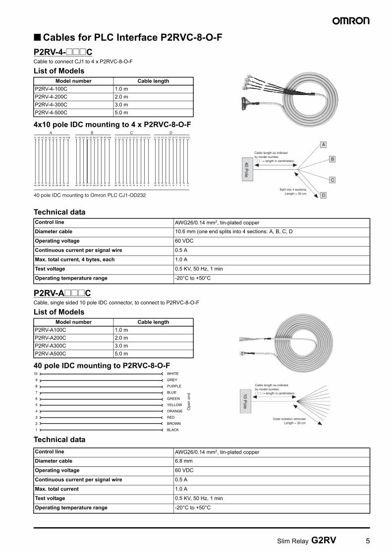
■ Cables for PLC Interface P2RVC-8-O-FP2RV-4-@@@CCable to connect CJ1 to 4 x P2RVC-8-O-F
List of Models
4x10 pole IDC mounting to 4 x P2RVC-8-O-F
Technical data
P2RV-A@@@CCable, single sided 10 pole IDC connector, to connect to P2RVC-8-O-F
List of Models
40 pole IDC mounting to P2RVC-8-O-F
Technical data
Model number Cable lengthP2RV-4-100C 1.0 mP2RV-4-200C 2.0 mP2RV-4-300C 3.0 mP2RV-4-500C 5.0 m
AA1 A2 A3 A4 A5 A6 A7 A8 A9 A100 B1 B2 B3 B4 B5 B6 B7 B8 B9 B100 C1 C2 C3 C4 C5 C6 C7 C8 C9 C10 D1 D2 D3 D4 D5 D6 D7 D8 D9 D10
B C D
40 38 36 34 32 30 28 26 22 24 39 37 35 33 31 29 27 25 21 23 20 18 16 14 12 10 8 6 2 4 19 17 15 13 11 9 7 5 1 3
40 pole IDC mounting to Omron PLC CJ1-OD232
Cable length as indictadby model number.@@@ = length in centimeters
Split into 4 sectionsLength = 30 cm
40 Pole
B
A
D
C
Control line AWG26/0.14 mm2, tin-plated copper
Diameter cable 10.6 mm (one end splits into 4 sections: A, B, C, D
Operating voltage 60 VDC
Continuous current per signal wire 0.5 A
Max. total current, 4 bytes, each 1.0 A
Test voltage 0.5 KV, 50 Hz, 1 min
Operating temperature range -20°C to +50°C
Model number Cable lengthP2RV-A100C 1.0 mP2RV-A200C 2.0 mP2RV-A300C 3.0 mP2RV-A500C 5.0 m
WHITE
GREY
PURPLE
BLUE
GREEN
YELLOW
ORANGE
RED
BROWN
BLACK
10
9
8
7
6
5
4
3
2
1
Ope
n en
d
Cable length as indictadby model number.@@@ = length in centimeters
Outer isolation removedLength = 30 cm
10 Pole
Control line AWG26/0.14 mm2, tin-plated copper
Diameter cable 6.8 mm
Operating voltage 60 VDC
Continuous current per signal wire 0.5 A
Max. total current 1.0 A
Test voltage 0.5 KV, 50 Hz, 1 min
Operating temperature range -20°C to +50°C
6 Slim Relay G2RV
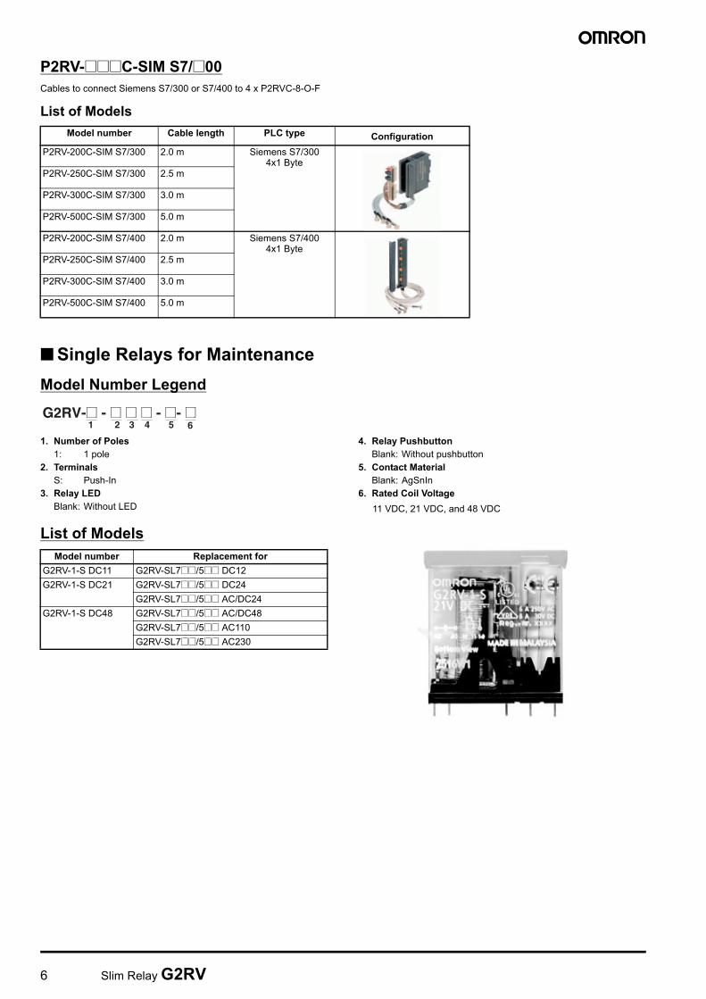
P2RV-@@@C-SIM S7/@00Cables to connect Siemens S7/300 or S7/400 to 4 x P2RVC-8-O-F
List of Models
■ Single Relays for MaintenanceModel Number Legend
1. Number of Poles1: 1 pole
2. TerminalsS: Push-In
3. Relay LEDBlank: Without LED
4. Relay PushbuttonBlank: Without pushbutton
5. Contact MaterialBlank: AgSnIn
6. Rated Coil Voltage11 VDC, 21 VDC, and 48 VDC
List of Models
Model number Cable length PLC type ConfigurationP2RV-200C-SIM S7/300 2.0 m Siemens S7/300
4x1 ByteP2RV-250C-SIM S7/300 2.5 m
P2RV-300C-SIM S7/300 3.0 m
P2RV-500C-SIM S7/300 5.0 m
P2RV-200C-SIM S7/400 2.0 m Siemens S7/4004x1 Byte
P2RV-250C-SIM S7/400 2.5 m
P2RV-300C-SIM S7/400 3.0 m
P2RV-500C-SIM S7/400 5.0 m
1 2 3 4 5 6G2RV-@ - @ @ @ - @- @
Model number Replacement forG2RV-1-S DC11 G2RV-SL7@@/5@@ DC12G2RV-1-S DC21 G2RV-SL7@@/5@@ DC24
G2RV-SL7@@/5@@ AC/DC24G2RV-1-S DC48 G2RV-SL7@@/5@@ AC/DC48
G2RV-SL7@@/5@@ AC110G2RV-SL7@@/5@@ AC230
Slim Relay G2RV 7
■ Cross barsModel Number Legend
1. Number of Poles 2. Color020: 2 poles R: Red030: 3 poles S: Blue040: 4 poles B: Black100: 10 poles200: 20 poles
List of Models
@ select color: R = Red, S=Blue, B=Black
Specification
■ Plastic Labels for G2RV Sockets
■ Labels (Stickers) for G2RV Sockets
Model number Poles Quantity ColorP2RVM-020@ 2 60 pcs / box (minimum order)
Red (R)Blue (S)Black (B)
P2RVM-030@ 3 60 pcs / box (minimum order)P2RVM-040@ 4 60 pcs / box (minimum order)P2RVM-100@ 10 20 pcs / box (minimum order)P2RVM-200@ 20 20 pcs / box (minimum order)
Max current(EN60947-7-1 section 8.3.3 / 1991)
32A
Max. Voltage 400 VACMax. Voltagewhen cutting Cross-bar without using separation plate or end-bracket
250 VAC
1 2P2RVM -@ @
Model number Box quantity ColorR99-15 for G2RV 5 sheets × 120 labels =
600 labels (minimum order)White
Model number Box quantity ColorR99-16 for G2RV 10 sheets × 484 labels =
4,840 labels (minimum order)White
8 Slim Relay G2RV
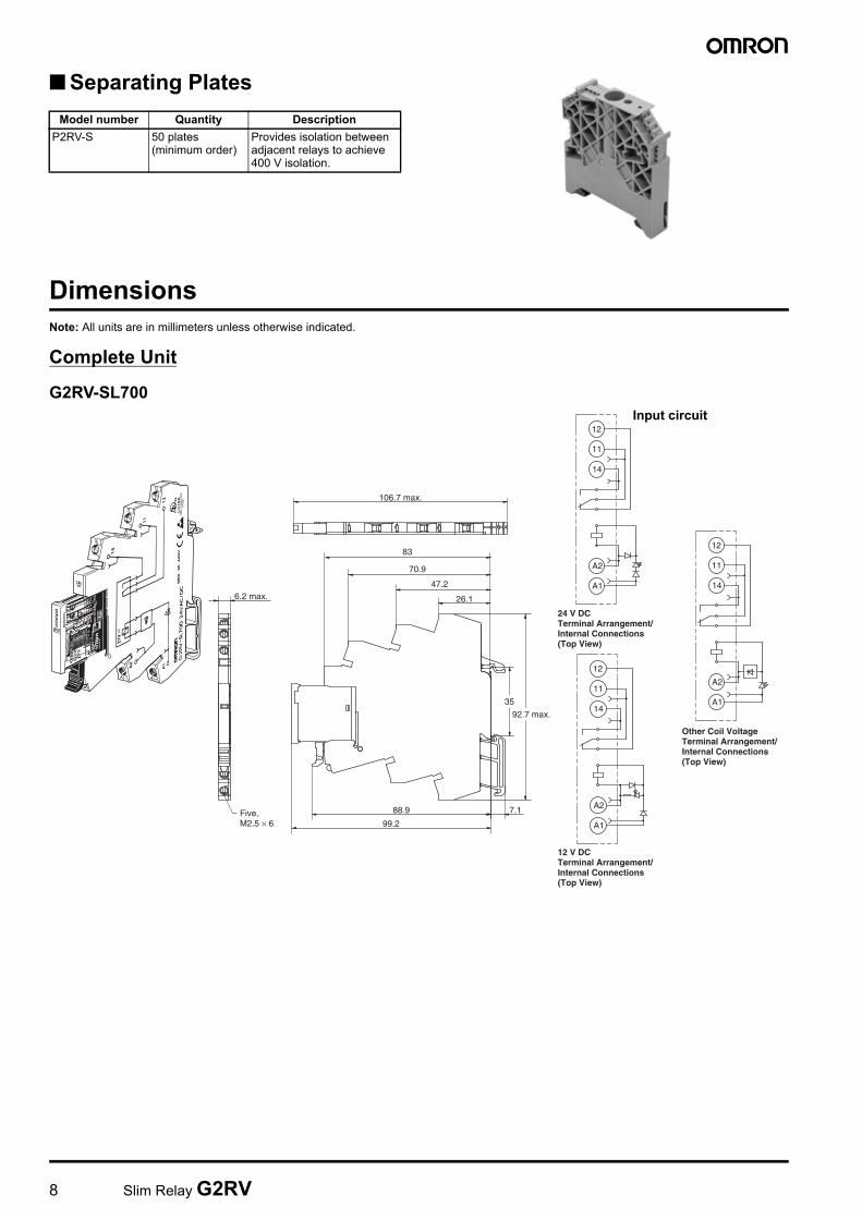
■ Separating Plates
DimensionsNote: All units are in millimeters unless otherwise indicated.
Complete Unit
G2RV-SL700
Model number Quantity DescriptionP2RV-S 50 plates
(minimum order)Provides isolation between adjacent relays to achieve 400 V isolation.
12
11
14
A1
A2
24 V DCTerminal Arrangement/Internal Connections(Top View)
12
11
14
A1
A2
12 V DCTerminal Arrangement/Internal Connections(Top View)
12
11
14
A1
A2
Other Coil VoltageTerminal Arrangement/Internal Connections(Top View)
Five, M2.5 × 6
6.2 max.
99.2
7.188.9
26.1
47.2
70.9
83
106.7 max.
92.7 max.
35
Input circuit

Slim Relay G2RV 9
G2RV-SL500
Single Relay
G2RV-1-S
12
11
14
A1
A2
24 V DCTerminal Arrangement/Internal Connections(Top View)
12
11
14
A1
A2
12 V DCTerminal Arrangement/Internal Connections
12
11
14
A1
A2
Other Coil VoltageTerminal Arrangement/Internal Connections(Top View)
6.2 max.
99.2
88.9 7.1
24.646
69.8
82.9
106.7 max.
97.4 max.35
Input circuit
A2A1121114
Terminal Arrangement/Internal Connections(Bottom View)
30.5 max.
3.5
0.5 2.41.8
5.2 max.
5.04 5.04
322
33 max.
16.2
Input circuit
10 Slim Relay G2RV
Installation
■ ToolsG2RV-SL700 series: Flat-Blade screwdriver should be used for mounting and / or releasing cables.G2RV-SL500 series: Flat-Blade screwdriver should be used for mounting stranded wires without ferrules and / or releasing cables.
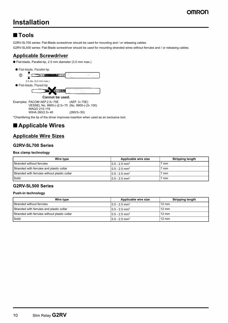
Applicable Screwdriver● Flat-blade, Parallel-tip, 2.5 mm diameter (3.0 mm max.)
Examples: FACOM AEF.2.5× 75E (AEF. 3× 75E)VESSEL No. 9900-(-)2.5× 75 (No. 9900-(-)3× 100)WAGO 210-119WIHA 260/2.5× 40 (260/3× 50)
*Chamfering the tip of the driver improves insertion when used as an exclusive tool.
■ Applicable Wires
Applicable Wire Sizes
G2RV-SL700 SeriesBox clamp technology
G2RV-SL500 SeriesPush-in technology
● Flat-blade, Parallel-tip
● Flat-blade, Flared-tip2.5 dia. (3.0 mm max.)
Cannot be used.
Wire type Applicable wire size Stripping lengthStranded without ferrules 0.5 - 2.5 mm2 7 mmStranded with ferrules and plastic collar 0.5 - 2.5 mm2 7 mmStranded with ferrules without plastic collar 0.5 - 2.5 mm2 7 mmSolid 0.5 - 2.5 mm2 7 mm
Wire type Applicable wire size Stripping lengthStranded without ferrules 0.5 - 2.5 mm2 12 mmStranded with ferrules and plastic collar 0.5 - 2.5 mm2 12 mmStranded with ferrules without plastic collar 0.5 - 2.5 mm2 12 mmSolid 0.5 - 2.5 mm2 12 mm
Slim Relay G2RV 11
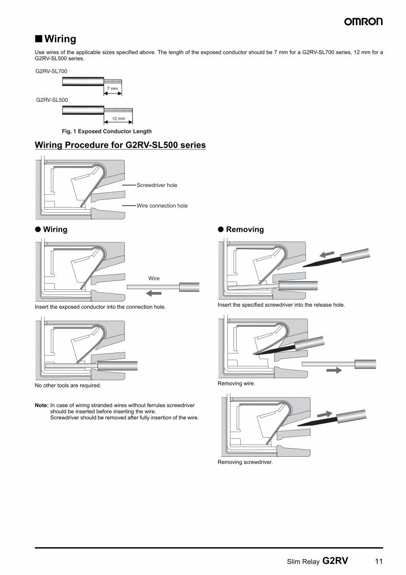
■ WiringUse wires of the applicable sizes specified above. The length of the exposed conductor should be 7 mm for a G2RV-SL700 series, 12 mm for aG2RV-SL500 series.
Wiring Procedure for G2RV-SL500 series
● Wiring
Insert the exposed conductor into the connection hole.
No other tools are required.
Note: In case of wiring stranded wires without ferrules screwdriver should be inserted before inserting the wire. Screwdriver should be removed after fully insertion of the wire.
● Removing
Insert the specified screwdriver into the release hole.
Removing wire.
Removing screwdriver.
7 mm
Fig. 1 Exposed Conductor Length
12 mm
G2RV-SL700
G2RV-SL500
Screwdriver hole
Wire connection hole
Wire
12 Slim Relay G2RV
Precautions
Precautions for Connection• Do not move the screwdriver up, down, or from side to side while it
is inserted in the hole. Doing so may cause damage to internal components (e.g., deformation of the clamp spring or cracks in the housing) or cause deterioration of insulation.
• Do not insert the screwdriver at an angle. Doing so may break the side of socket and result in a short-circuit.
• Do not insert two or more wires in the hole. Wires may come in contact with the spring causing a temperature rise or be subject to sparks.
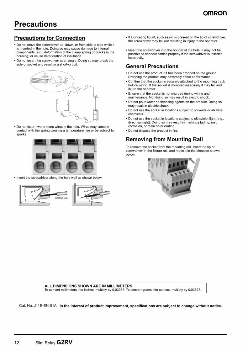
• Insert the screwdriver along the hole wall as shown below.
• If lubricating liquid, such as oil, is present on the tip of screwdriver, the screwdriver may fall out resulting in injury to the operator.
• Insert the screwdriver into the bottom of the hole. It may not be possible to connect cables properly if the screwdriver is inserted incorrectly.
General Precautions• Do not use the product if it has been dropped on the ground.
Dropping the product may adversely affect performance.• Confirm that the socket is securely attached to the mounting track
before wiring. If the socket is mounted insecurely it may fall and injure the operator.
• Ensure that the socket is not charged during wiring and maintenance. Not doing so may result in electric shock.
• Do not pour water or cleansing agents on the product. Doing so may result in electric shock.
• Do not use the socket in locations subject to solvents or alkaline chemicals.
• Do not use the socket in locations subject to ultraviolet light (e.g., direct sunlight). Doing so may result in markings fading, rust, corrosion, or resin deterioration.
• Do not dispose the product in fire.
Removing from Mounting RailTo remove the socket from the mounting rail, insert the tip of screwdriver in the fixture rail, and move it in the direction shown below.
Screwdriver
In the interest of product improvement, specifications are subject to change without notice.
ALL DIMENSIONS SHOWN ARE IN MILLIMETERS.To convert millimeters into inches, multiply by 0.03937. To convert grams into ounces, multiply by 0.03527.
Cat. No. J11E-EN-01A