Embed Size (px)
Citation preview

Preventa™ Machine Safety ProductsCatalog
2014Chapter 3Safety Relays
3
3/1
Contents chapter 3 Safety relays
Safety relay modulesSelection guide: Preventa™ safety relay modules . . . . . . . . . . . . 3/6
Electrical ratings . . . . . . . . . . . . . . . . . . . . . . . . . . . . . . . . . . . . . . . . . . . . . . . . 3/16
For Emergency stop and switch monitoringb Types XPSAC, XPSAXE . . . . . . . . . . . . . . . . . . . . . . . . . . . . . . . . . . . . . . . . . 3/18b Types XPSAV, XPSABV, XPSATE . . . . . . . . . . . . . . . . . . . . . . . . . . . . . . . . . . 3/22b Type XPSATR . . . . . . . . . . . . . . . . . . . . . . . . . . . . . . . . . . . . . . . . . . . . . . . . . 3/32b Type XPSAF . . . . . . . . . . . . . . . . . . . . . . . . . . . . . . . . . . . . . . . . . . . . . . . . . . 3/36b Type XPSAFL . . . . . . . . . . . . . . . . . . . . . . . . . . . . . . . . . . . . . . . . . . . . . . . . . 3/40
For Emergency stop, switch or light curtain monitoringb Type XPSAR . . . . . . . . . . . . . . . . . . . . . . . . . . . . . . . . . . . . . . . . . . . . . . . . . . 3/44
For Emergency stop, switch, sensing mat/edges or light curtain monitoring b Type XPSAK . . . . . . . . . . . . . . . . . . . . . . . . . . . . . . . . . . . . . . . . . . . . . . . . . . 3/50
For electrical monitoring of two-hand control stations b Types XPSBAE, XPSBCE, XPSBF . . . . . . . . . . . . . . . . . . . . . . . . . . . . . . . . . 3/56
For forming a type 2 light curtainb Types XPSCM, XU2S (single-beam photoelectric sensor) . . . . . . . . . . . . . . . 3/64
For monitoring 2 to 4 light curtains type 2 and type 4 b Type XPSLCD . . . . . . . . . . . . . . . . . . . . . . . . . . . . . . . . . . . . . . . . . . . . . . . . . 3/72
For “muting” function of type 2 and type 4 light curtains b Type XPSLCM . . . . . . . . . . . . . . . . . . . . . . . . . . . . . . . . . . . . . . . . . . . . . . . . . 3/76
For increasing the number of safety contacts b Types XPSECME, XPSECPE . . . . . . . . . . . . . . . . . . . . . . . . . . . . . . . . . . . . . 3/84
For safety time delays b Types XPSTSA, XPSTSW . . . . . . . . . . . . . . . . . . . . . . . . . . . . . . . . . . . . . . . 3/88
For non-contact safety interlock (coded magnetic) switch monitoring b Types XPSDMB, XPSDME . . . . . . . . . . . . . . . . . . . . . . . . . . . . . . . . . . . . . . . 3/92
For zero speed detection b Type XPSVNE . . . . . . . . . . . . . . . . . . . . . . . . . . . . . . . . . . . . . . . . . . . . . . . . . 3/98
For dynamic monitoring of hydraulic valves on linear presses b Type XPSPVT . . . . . . . . . . . . . . . . . . . . . . . . . . . . . . . . . . . . . . . . . . . . . . . . 3/104
For dynamic monitoring of double-bodied solenoid valves b Type XPSPVK . . . . . . . . . . . . . . . . . . . . . . . . . . . . . . . . . . . . . . . . . . . . . . . . 3/108
For safety stop with automatic overtravel monitoring and control b Type XPSOT . . . . . . . . . . . . . . . . . . . . . . . . . . . . . . . . . . . . . . . . . . . . . . . . . 3/112
Dimensions . . . . . . . . . . . . . . . . . . . . . . . . . . . . . . . . . . . . . . . . . . . . . . . . . . . 3/116
Safety solutions on AS-Interface™ cabling systemSelection guide: Safety monitors and interfaces . . . . . . . . . . . 3/118
AS-Interface “Safety at work” monitors . . . . . . . . . . . . . . . . . . . . . . . . . . . . 3/120
Safety interfaces . . . . . . . . . . . . . . . . . . . . . . . . . . . . . . . . . . . . . . . . . . . . . . . 3/124
Safety reliability valuesSafety reliability values according to standard EN/ISO 13849-1 and EN/IEC 62061 . . . . . . . . . . . . . . 3/128
Product reference index . . . . . . . . . . . . . . . . . . . . . . . . . . . . . . . . . . . . 3/132

3/2
1. Go to: www.schneider-electric.com and select “Products” on the “Products and Services” tab.
1
Go online to www.schneider-electric.com for information about Preventa™ products listed in this catalog, including:
1
2
2. On the “Products” page, find the “Machine Safety Products” icon and select “All Machine Safety Products”.
2

3/3
> Specifications > Dimensions > References> Curves > Links to user guides and CAD files
3 On the “Machine Safety Products” page, select the product you are interested in, for example: “Safety Relays - Preventa XPS - Safety Modules”.
3
3
4
4 Explore the product page you have selected, including the “Product Information” tabs: “Documents & Downloads” and “Support”.
4
3/4
Preventa™
Machine safety products
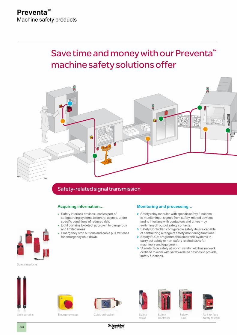
Save time and money with our Preventa™ machine safety solutions offer
Acquiring information…
> Safety interlock devices used as part of safeguarding systems to control access, under specific conditions of reduced risk.
> Light curtains to detect approach to dangerous and limited areas.
> Emergency stop buttons and cable pull switches for emergency shut down.
Monitoring and processing…
> Safety relay modules with specific safety functions – to monitor input signals from safety-related devices, and to interface with contactors and drives – by switching off output safety contacts.
> Safety Controller: configurable safety device capable of centralizing a range of safety monitoring functions.
> Safety PLCs: programmable electronic systems to carry out safety or non-safety related tasks for machinery and equipment.
> “As-interface safety at work”: safety field bus network certified to work with safety-related devices to provide safety functions.
Safety interlocks
Light curtains Emergency stop Safety relays
Safety Controller
SafetyPLCs
As-interface safety at work
Cable pull switch
Safety-related signal transmission
3/5
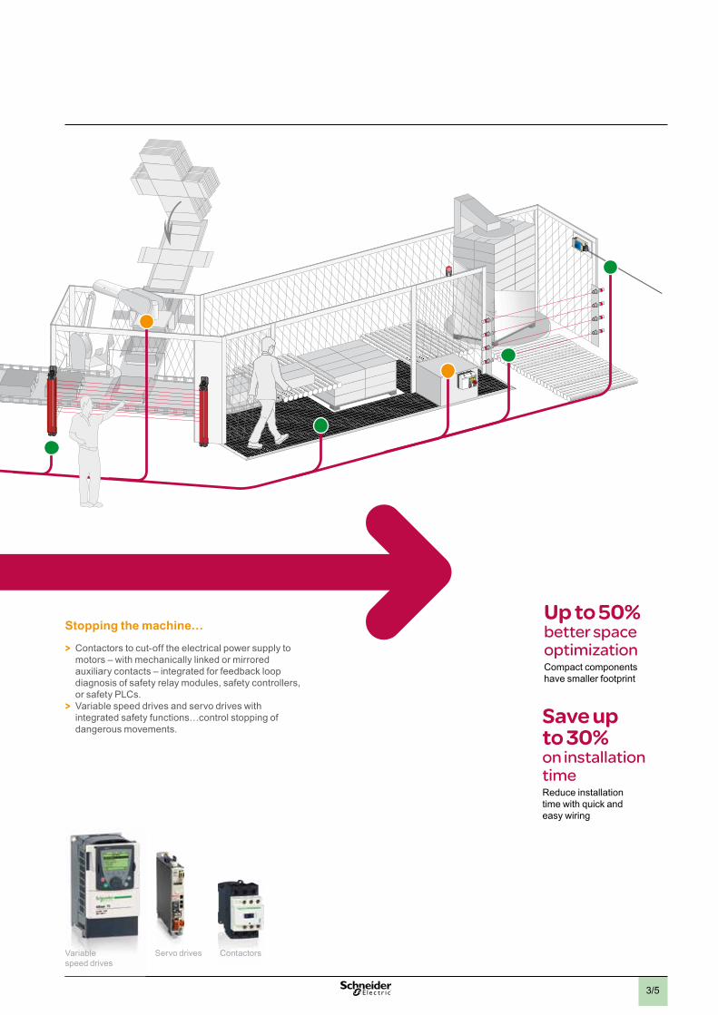
Up to 50% better space optimizationCompact components have smaller footprint
Save up to 30%on installation timeReduce installation time with quick and easy wiring
Stopping the machine…
> Contactors to cut-off the electrical power supply to motors – with mechanically linked or mirrored auxiliary contacts – integrated for feedback loop diagnosis of safety relay modules, safety controllers, or safety PLCs.
> Variable speed drives and servo drives with integrated safety functions…control stopping of dangerous movements.
Variable speed drives
ContactorsServo drives
3
3/6
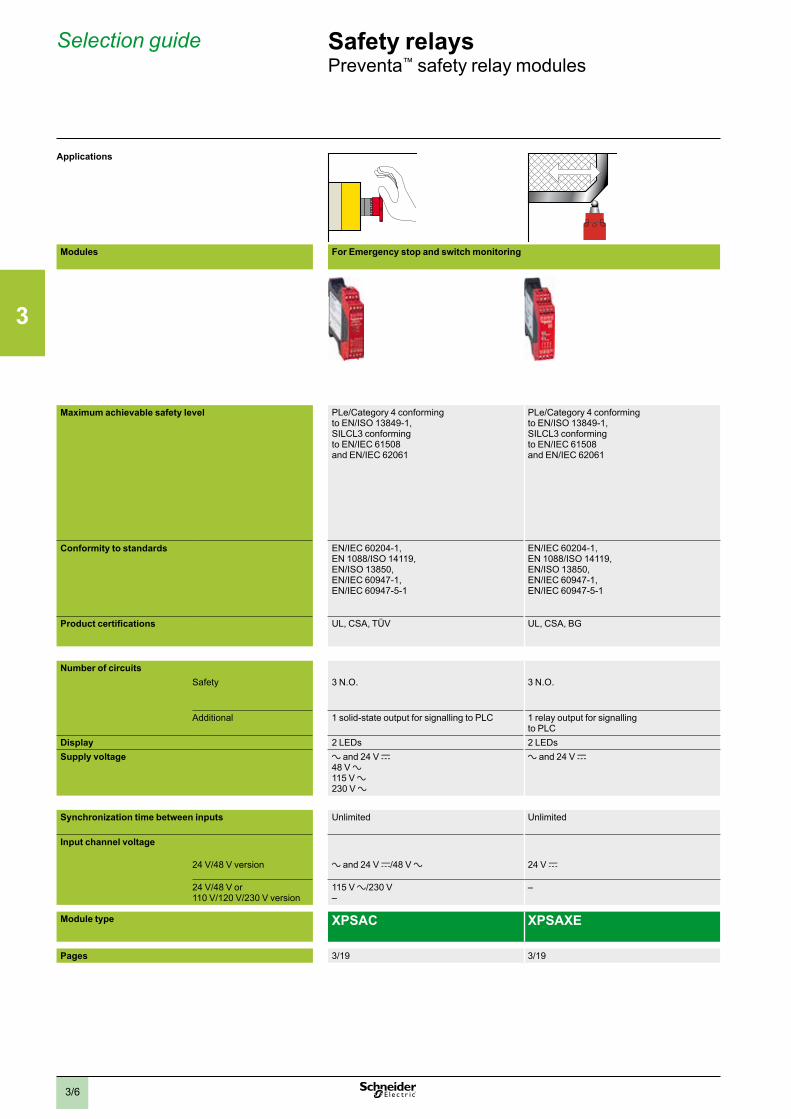
Selection guide Safety relaysPreventa™ safety relay modules
Applications
Modules For Emergency stop and switch monitoring For Emergency stop and switch monitoring
For Emergency stop and protective guard applications
For Emergency stop and switch monitoring
Maximum achievable safety level PLe/Category 4 conforming to EN/ISO 13849-1,SILCL3 conforming to EN/IEC 61508 and EN/IEC 62061
PLe/Category 4 conforming to EN/ISO 13849-1,SILCL3 conforming to EN/IEC 61508 and EN/IEC 62061
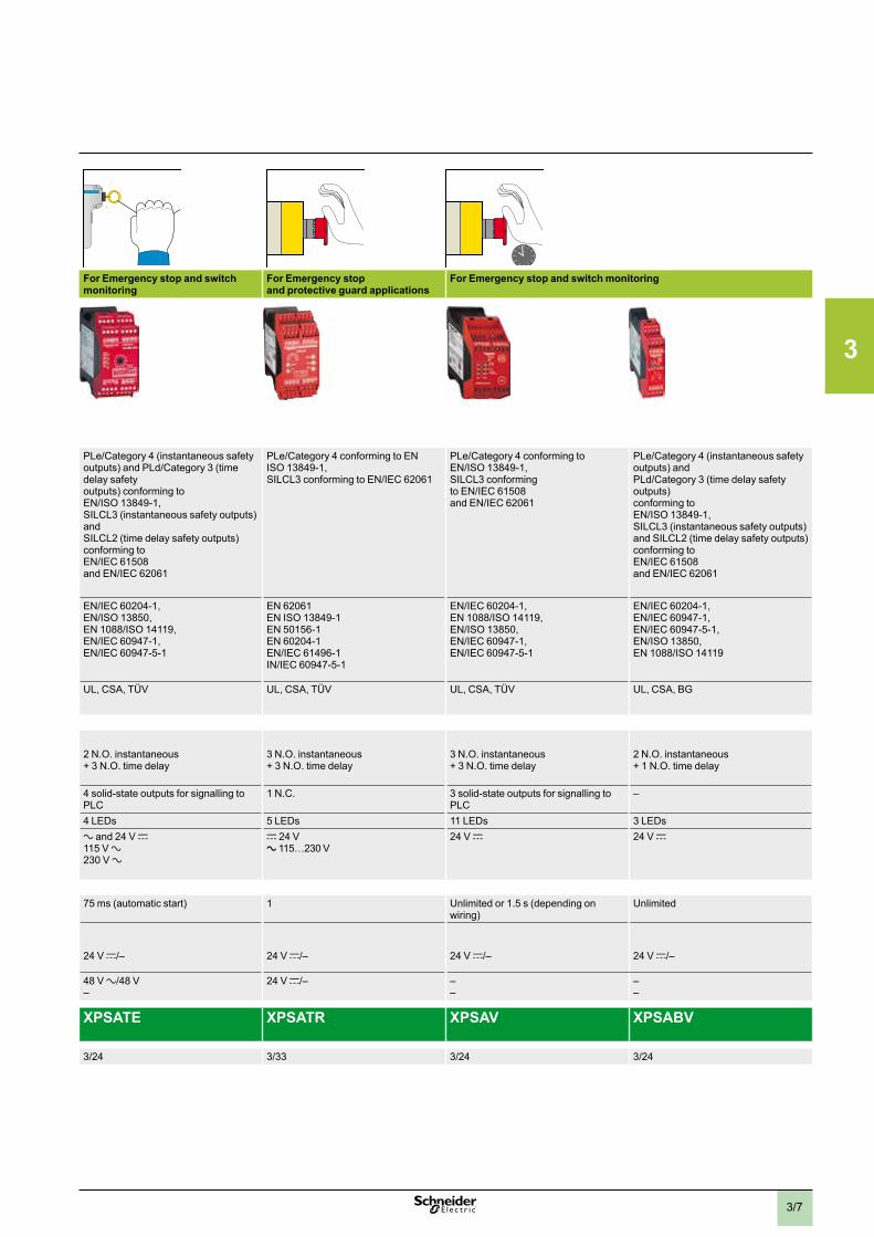
PLe/Category 4 (instantaneous safety outputs) and PLd/Category 3 (time delay safety outputs) conforming to EN/ISO 13849-1,SILCL3 (instantaneous safety outputs) and SILCL2 (time delay safety outputs) conforming to EN/IEC 61508 and EN/IEC 62061
PLe/Category 4 conforming to EN ISO 13849-1,SILCL3 conforming to EN/IEC 62061
PLe/Category 4 conforming to EN/ISO 13849-1, SILCL3 conforming to EN/IEC 61508 and EN/IEC 62061
PLe/Category 4 (instantaneous safety outputs) and PLd/Category 3 (time delay safety outputs) conforming to EN/ISO 13849-1, SILCL3 (instantaneous safety outputs) and SILCL2 (time delay safety outputs) conforming to EN/IEC 61508 and EN/IEC 62061
Conformity to standards EN/IEC 60204-1,EN 1088/ISO 14119,EN/ISO 13850,EN/IEC 60947-1,EN/IEC 60947-5-1
EN/IEC 60204-1,EN 1088/ISO 14119,EN/ISO 13850,EN/IEC 60947-1,EN/IEC 60947-5-1
EN/IEC 60204-1,EN/ISO 13850,EN 1088/ISO 14119,EN/IEC 60947-1,EN/IEC 60947-5-1
EN 62061EN ISO 13849-1EN 50156-1EN 60204-1EN/IEC 61496-1IN/IEC 60947-5-1
EN/IEC 60204-1,EN 1088/ISO 14119,EN/ISO 13850,EN/IEC 60947-1,EN/IEC 60947-5-1
EN/IEC 60204-1,EN/IEC 60947-1,EN/IEC 60947-5-1,EN/ISO 13850,EN 1088/ISO 14119
Product certifications UL, CSA, TÜV UL, CSA, BG UL, CSA, TÜV UL, CSA, TÜV UL, CSA, TÜV UL, CSA, BG
Number of circuitsSafety 3 N.O. 3 N.O. 2 N.O. instantaneous
+ 3 N.O. time delay3 N.O. instantaneous + 3 N.O. time delay
3 N.O. instantaneous + 3 N.O. time delay
2 N.O. instantaneous + 1 N.O. time delay
Additional 1 solid-state output for signalling to PLC 1 relay output for signalling to PLC
4 solid-state outputs for signalling to PLC
1 N.C. 3 solid-state outputs for signalling to PLC
–
Display 2 LEDs 2 LEDs 4 LEDs 5 LEDs 11 LEDs 3 LEDsSupply voltage a and 24 V c
48 V a115 V a230 V a
a and 24 V c a and 24 V c115 V a230 V a
c 24 Va 115…230 V
24 V c 24 V c
Synchronization time between inputs Unlimited Unlimited 75 ms (automatic start) 1 Unlimited or 1.5 s (depending on wiring)
Unlimited
Input channel voltage
24 V/48 V version a and 24 V c/48 V a 24 V c 24 V c/– 24 V c/– 24 V c/– 24 V c/–
24 V/48 V or 110 V/120 V/230 V version
115 V a/230 V–
– 48 V a/48 V–
24 V c/– ––
––
Module type XPSAC XPSAXE XPSATE XPSATR XPSAV XPSABV
Pages 3/19 3/19 3/24 3/33 3/24 3/24
3
3/7
Applications
Modules For Emergency stop and switch monitoring For Emergency stop and switch monitoring
For Emergency stop and protective guard applications
For Emergency stop and switch monitoring
Maximum achievable safety level PLe/Category 4 conforming to EN/ISO 13849-1,SILCL3 conforming to EN/IEC 61508 and EN/IEC 62061
PLe/Category 4 conforming to EN/ISO 13849-1,SILCL3 conforming to EN/IEC 61508 and EN/IEC 62061
PLe/Category 4 (instantaneous safety outputs) and PLd/Category 3 (time delay safety outputs) conforming to EN/ISO 13849-1,SILCL3 (instantaneous safety outputs) and SILCL2 (time delay safety outputs) conforming to EN/IEC 61508 and EN/IEC 62061
PLe/Category 4 conforming to EN ISO 13849-1,SILCL3 conforming to EN/IEC 62061
PLe/Category 4 conforming to EN/ISO 13849-1, SILCL3 conforming to EN/IEC 61508 and EN/IEC 62061
PLe/Category 4 (instantaneous safety outputs) and PLd/Category 3 (time delay safety outputs) conforming to EN/ISO 13849-1, SILCL3 (instantaneous safety outputs) and SILCL2 (time delay safety outputs) conforming to EN/IEC 61508 and EN/IEC 62061
Conformity to standards EN/IEC 60204-1,EN 1088/ISO 14119,EN/ISO 13850,EN/IEC 60947-1,EN/IEC 60947-5-1
EN/IEC 60204-1,EN 1088/ISO 14119,EN/ISO 13850,EN/IEC 60947-1,EN/IEC 60947-5-1
EN/IEC 60204-1,EN/ISO 13850,EN 1088/ISO 14119,EN/IEC 60947-1,EN/IEC 60947-5-1
EN 62061EN ISO 13849-1EN 50156-1EN 60204-1EN/IEC 61496-1IN/IEC 60947-5-1
EN/IEC 60204-1,EN 1088/ISO 14119,EN/ISO 13850,EN/IEC 60947-1,EN/IEC 60947-5-1
EN/IEC 60204-1,EN/IEC 60947-1,EN/IEC 60947-5-1,EN/ISO 13850,EN 1088/ISO 14119
Product certifications UL, CSA, TÜV UL, CSA, BG UL, CSA, TÜV UL, CSA, TÜV UL, CSA, TÜV UL, CSA, BG
Number of circuitsSafety 3 N.O. 3 N.O. 2 N.O. instantaneous
+ 3 N.O. time delay3 N.O. instantaneous + 3 N.O. time delay
3 N.O. instantaneous + 3 N.O. time delay
2 N.O. instantaneous + 1 N.O. time delay
Additional 1 solid-state output for signalling to PLC 1 relay output for signalling to PLC
4 solid-state outputs for signalling to PLC
1 N.C. 3 solid-state outputs for signalling to PLC
–
Display 2 LEDs 2 LEDs 4 LEDs 5 LEDs 11 LEDs 3 LEDsSupply voltage a and 24 V c
48 V a115 V a230 V a
a and 24 V c a and 24 V c115 V a230 V a
c 24 Va 115…230 V
24 V c 24 V c
Synchronization time between inputs Unlimited Unlimited 75 ms (automatic start) 1 Unlimited or 1.5 s (depending on wiring)
Unlimited
Input channel voltage
24 V/48 V version a and 24 V c/48 V a 24 V c 24 V c/– 24 V c/– 24 V c/– 24 V c/–
24 V/48 V or 110 V/120 V/230 V version
115 V a/230 V–
– 48 V a/48 V–
24 V c/– ––
––
Module type XPSAC XPSAXE XPSATE XPSATR XPSAV XPSABV
Pages 3/19 3/19 3/24 3/33 3/24 3/24
3
3/8
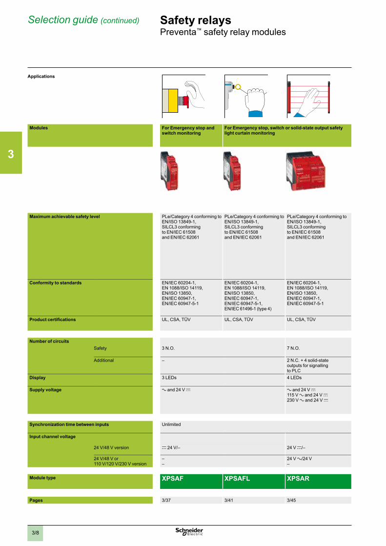
Selection guide (continued) Safety relaysPreventa™ safety relay modules
Applications
Modules For Emergency stop and switch monitoring
For Emergency stop, switch or solid-state output safety light curtain monitoring
For Emergency stop, switch, sensing mat/edges or solid-state output safety light curtain monitoring
For electrical monitoring of two-hand control stations
Maximum achievable safety level PLe/Category 4 conforming to EN/ISO 13849-1,SILCL3 conforming to EN/IEC 61508 and EN/IEC 62061
PLe/Category 4 conforming to EN/ISO 13849-1,SILCL3 conforming to EN/IEC 61508 and EN/IEC 62061
PLe/Category 4 conforming to EN/ISO 13849-1, SILCL3 conforming to EN/IEC 61508 and EN/IEC 62061
PLe/Category 4 conforming to EN/ISO 13849-1, SILCL3 conforming to EN/IEC 61508 and EN/IEC 62061
PLc/Category 1 conforming to EN/ISO 13849-1 SILCL1 conforming to EN/IEC 62061
PLe/Category 4 conforming to EN/ISO 13849-1, SILCL3 conforming to EN/IEC 61508 and EN/IEC 62061
PLe/Category 4 conforming to EN/ISO 13849-1,SILCL3 conforming to EN/IEC 61508 and EN/IEC 62061
Conformity to standards EN/IEC 60204-1,EN 1088/ISO 14119,EN/ISO 13850,EN/IEC 60947-1,EN/IEC 60947-5-1
EN/IEC 60204-1,EN 1088/ISO 14119,EN/ISO 13850,EN/IEC 60947-1,EN/IEC 60947-5-1,EN/IEC 61496-1 (type 4)
EN/IEC 60204-1,EN 1088/ISO 14119,EN/ISO 13850,EN/IEC 60947-1,EN/IEC 60947-5-1
EN/IEC 60204-1,EN 1088/ISO 14119,EN/ISO 13850,EN/IEC 60947-1,EN/IEC 60947-5-1
EN 574 type III A, EN/IEC 60204-1,EN/IEC 60947-5-1,EN 62061
EN/IEC 60204-1,EN/IEC 60947-1,EN/IEC 60947-5-1,EN 574 type III C/ISO 13851
EN/IEC 60204-1,EN/IEC 60947-1,EN/IEC 60947-5-1,EN 574 type III C/ISO 13851
Product certifications UL, CSA, TÜV UL, CSA, TÜV UL, CSA, TÜV UL, CSA, TÜV UL, CSA, TÜV UL, CSA, BG UL, CSA, TÜV
Number of circuitsSafety 3 N.O. 7 N.O. 3 N.O. instantaneous 1 N.O. 2 N.O. 2 N.O.
Additional – 2 N.C. + 4 solid-state outputs for signalling to PLC
1 N.C. + 4 solid-state outputs for signalling to PLC
1 N.C. 1 N.C. 2 solid-state outputs for signalling to PLC
Display 3 LEDs 4 LEDs 4 LEDs 2 LEDs 3 LEDs 3 LEDs
Supply voltage a and 24 V c a and 24 V c115 V a and 24 V c230 V a and 24 V c
a and 24 V c48 V a110 V a and 24 V c120 V a and 24 V c230 V a and 24 V c
a and 24 V c115/230 V a
a and 24 V c115/120 V a230 V a
24 V c
Synchronization time between inputs Unlimited Unlimited or 2 s, 4 s (depending on wiring)
500 ms 500 ms 500 ms
Input channel voltage
24 V/48 V version c 24 V/– 24 V c/– 24 V c/– 24 V c/– 24 V c 24 V c/–
24 V/48 V or 110 V/120 V/230 V version
––
24 V a/24 V–
–24 V c/24 V/24 V
–24 V a/24 V
––
––
Module type XPSAF XPSAFL XPSAR XPSAK XPSBAE XPSBCE XPSBF
Pages 3/37 3/41 3/45 3/51 3/59 3/59 3/59

3
3/9
Applications
Modules For Emergency stop and switch monitoring
For Emergency stop, switch or solid-state output safety light curtain monitoring
For Emergency stop, switch, sensing mat/edges or solid-state output safety light curtain monitoring
For electrical monitoring of two-hand control stations
Maximum achievable safety level PLe/Category 4 conforming to EN/ISO 13849-1,SILCL3 conforming to EN/IEC 61508 and EN/IEC 62061
PLe/Category 4 conforming to EN/ISO 13849-1,SILCL3 conforming to EN/IEC 61508 and EN/IEC 62061
PLe/Category 4 conforming to EN/ISO 13849-1, SILCL3 conforming to EN/IEC 61508 and EN/IEC 62061
PLe/Category 4 conforming to EN/ISO 13849-1, SILCL3 conforming to EN/IEC 61508 and EN/IEC 62061
PLc/Category 1 conforming to EN/ISO 13849-1 SILCL1 conforming to EN/IEC 62061
PLe/Category 4 conforming to EN/ISO 13849-1, SILCL3 conforming to EN/IEC 61508 and EN/IEC 62061
PLe/Category 4 conforming to EN/ISO 13849-1,SILCL3 conforming to EN/IEC 61508 and EN/IEC 62061
Conformity to standards EN/IEC 60204-1,EN 1088/ISO 14119,EN/ISO 13850,EN/IEC 60947-1,EN/IEC 60947-5-1
EN/IEC 60204-1,EN 1088/ISO 14119,EN/ISO 13850,EN/IEC 60947-1,EN/IEC 60947-5-1,EN/IEC 61496-1 (type 4)
EN/IEC 60204-1,EN 1088/ISO 14119,EN/ISO 13850,EN/IEC 60947-1,EN/IEC 60947-5-1
EN/IEC 60204-1,EN 1088/ISO 14119,EN/ISO 13850,EN/IEC 60947-1,EN/IEC 60947-5-1
EN 574 type III A, EN/IEC 60204-1,EN/IEC 60947-5-1,EN 62061
EN/IEC 60204-1,EN/IEC 60947-1,EN/IEC 60947-5-1,EN 574 type III C/ISO 13851
EN/IEC 60204-1,EN/IEC 60947-1,EN/IEC 60947-5-1,EN 574 type III C/ISO 13851
Product certifications UL, CSA, TÜV UL, CSA, TÜV UL, CSA, TÜV UL, CSA, TÜV UL, CSA, TÜV UL, CSA, BG UL, CSA, TÜV
Number of circuitsSafety 3 N.O. 7 N.O. 3 N.O. instantaneous 1 N.O. 2 N.O. 2 N.O.
Additional – 2 N.C. + 4 solid-state outputs for signalling to PLC
1 N.C. + 4 solid-state outputs for signalling to PLC
1 N.C. 1 N.C. 2 solid-state outputs for signalling to PLC
Display 3 LEDs 4 LEDs 4 LEDs 2 LEDs 3 LEDs 3 LEDs
Supply voltage a and 24 V c a and 24 V c115 V a and 24 V c230 V a and 24 V c
a and 24 V c48 V a110 V a and 24 V c120 V a and 24 V c230 V a and 24 V c
a and 24 V c115/230 V a
a and 24 V c115/120 V a230 V a
24 V c
Synchronization time between inputs Unlimited Unlimited or 2 s, 4 s (depending on wiring)
500 ms 500 ms 500 ms
Input channel voltage
24 V/48 V version c 24 V/– 24 V c/– 24 V c/– 24 V c/– 24 V c 24 V c/–
24 V/48 V or 110 V/120 V/230 V version
––
24 V a/24 V–
–24 V c/24 V/24 V
–24 V a/24 V
––
––
Module type XPSAF XPSAFL XPSAR XPSAK XPSBAE XPSBCE XPSBF
Pages 3/37 3/41 3/45 3/51 3/59 3/59 3/59
3
3/10
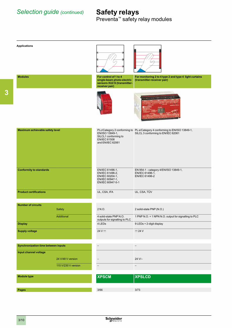
Selection guide (continued) Safety relaysPreventa™ safety relay modules
Applications
Modules For control of 1 to 4 single-beam photo-electric sensors XU2 S (transmitter-receiver pair)
For monitoring 2 to 4 type 2 and type 4 light curtains (transmitter-receiver pair)
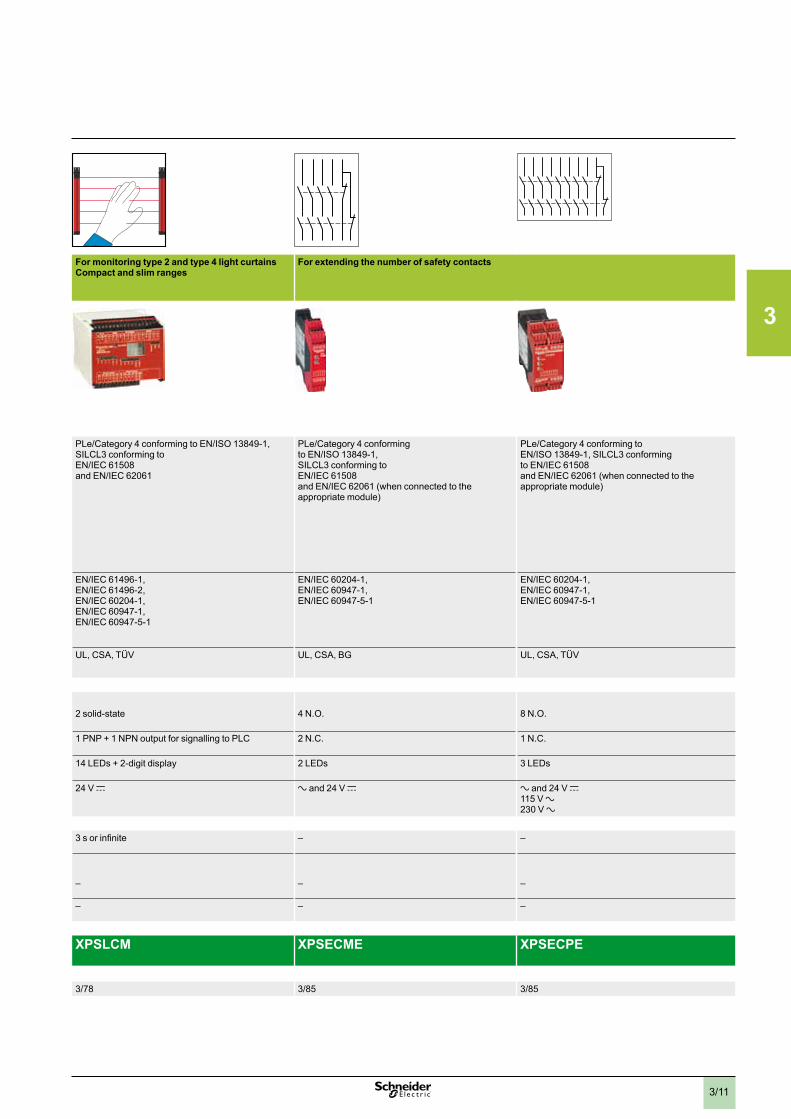
For monitoring type 2 and type 4 light curtainsCompact and slim ranges
For extending the number of safety contacts
Maximum achievable safety level PLc/Category 2 conforming to EN/ISO 13849-1,SILCL1 conforming to EN/IEC 61508 and EN/IEC 62061
PL e/Category 4 conforming to EN/ISO 13849-1, SILCL 3 conforming to EN/IEC 62061
PLe/Category 4 conforming to EN/ISO 13849-1,SILCL3 conforming to EN/IEC 61508 and EN/IEC 62061
PLe/Category 4 conforming to EN/ISO 13849-1,SILCL3 conforming to EN/IEC 61508 and EN/IEC 62061 (when connected to the appropriate module)
PLe/Category 4 conforming to EN/ISO 13849-1, SILCL3 conforming to EN/IEC 61508 and EN/IEC 62061 (when connected to the appropriate module)
Conformity to standards EN/IEC 61496-1,EN/IEC 61496-2,EN/IEC 60204-1,EN/IEC 60947-1,EN/IEC 60947-5-1
EN 954-1 - category 4/EN/ISO 13849-1,EN/IEC 61496-1,EN/IEC 61496-2
EN/IEC 61496-1,EN/IEC 61496-2,EN/IEC 60204-1,EN/IEC 60947-1,EN/IEC 60947-5-1
EN/IEC 60204-1,EN/IEC 60947-1,EN/IEC 60947-5-1
EN/IEC 60204-1,EN/IEC 60947-1,EN/IEC 60947-5-1
Product certifications UL, CSA, IFA UL, CSA, TÜV UL, CSA, TÜV UL, CSA, BG UL, CSA, TÜV
Number of circuitsSafety 2 N.O. 2 solid-state PNP (N.O.) 2 solid-state 4 N.O. 8 N.O.
Additional 4 solid-state PNP N.O. outputs for signalling to PLC
1 PNP N.O. + 1 NPN N.O. output for signalling to PLC 1 PNP + 1 NPN output for signalling to PLC 2 N.C. 1 N.C.
Display 4 LEDs 9 LEDs + 2-digit display 14 LEDs + 2-digit display 2 LEDs 3 LEDs
Supply voltage 24 V c c 24 V 24 V c a and 24 V c a and 24 V c115 V a230 V a
Synchronization time between inputs – – 3 s or infinite – –
Input channel voltage
24 V/48 V version – 24 V/– – – –
115 V/230 V version – – – – –
Module type XPSCM XPSLCD XPSLCM XPSECME XPSECPE
Pages 3/66 3/73 3/78 3/85 3/85
3
3/11
Applications
Modules For control of 1 to 4 single-beam photo-electric sensors XU2 S (transmitter-receiver pair)
For monitoring 2 to 4 type 2 and type 4 light curtains (transmitter-receiver pair)
For monitoring type 2 and type 4 light curtainsCompact and slim ranges
For extending the number of safety contacts
Maximum achievable safety level PLc/Category 2 conforming to EN/ISO 13849-1,SILCL1 conforming to EN/IEC 61508 and EN/IEC 62061
PL e/Category 4 conforming to EN/ISO 13849-1, SILCL 3 conforming to EN/IEC 62061
PLe/Category 4 conforming to EN/ISO 13849-1,SILCL3 conforming to EN/IEC 61508 and EN/IEC 62061
PLe/Category 4 conforming to EN/ISO 13849-1,SILCL3 conforming to EN/IEC 61508 and EN/IEC 62061 (when connected to the appropriate module)
PLe/Category 4 conforming to EN/ISO 13849-1, SILCL3 conforming to EN/IEC 61508 and EN/IEC 62061 (when connected to the appropriate module)
Conformity to standards EN/IEC 61496-1,EN/IEC 61496-2,EN/IEC 60204-1,EN/IEC 60947-1,EN/IEC 60947-5-1
EN 954-1 - category 4/EN/ISO 13849-1,EN/IEC 61496-1,EN/IEC 61496-2
EN/IEC 61496-1,EN/IEC 61496-2,EN/IEC 60204-1,EN/IEC 60947-1,EN/IEC 60947-5-1
EN/IEC 60204-1,EN/IEC 60947-1,EN/IEC 60947-5-1
EN/IEC 60204-1,EN/IEC 60947-1,EN/IEC 60947-5-1
Product certifications UL, CSA, IFA UL, CSA, TÜV UL, CSA, TÜV UL, CSA, BG UL, CSA, TÜV
Number of circuitsSafety 2 N.O. 2 solid-state PNP (N.O.) 2 solid-state 4 N.O. 8 N.O.
Additional 4 solid-state PNP N.O. outputs for signalling to PLC
1 PNP N.O. + 1 NPN N.O. output for signalling to PLC 1 PNP + 1 NPN output for signalling to PLC 2 N.C. 1 N.C.
Display 4 LEDs 9 LEDs + 2-digit display 14 LEDs + 2-digit display 2 LEDs 3 LEDs
Supply voltage 24 V c c 24 V 24 V c a and 24 V c a and 24 V c115 V a230 V a
Synchronization time between inputs – – 3 s or infinite – –
Input channel voltage
24 V/48 V version – 24 V/– – – –
115 V/230 V version – – – – –
Module type XPSCM XPSLCD XPSLCM XPSECME XPSECPE
Pages 3/66 3/73 3/78 3/85 3/85
3
3/12
Selection guide (continued) Safety relaysPreventa™ safety relay modules
Applications
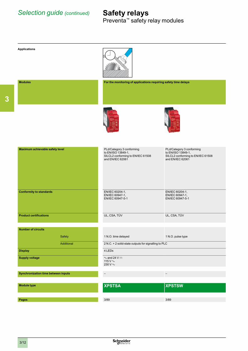
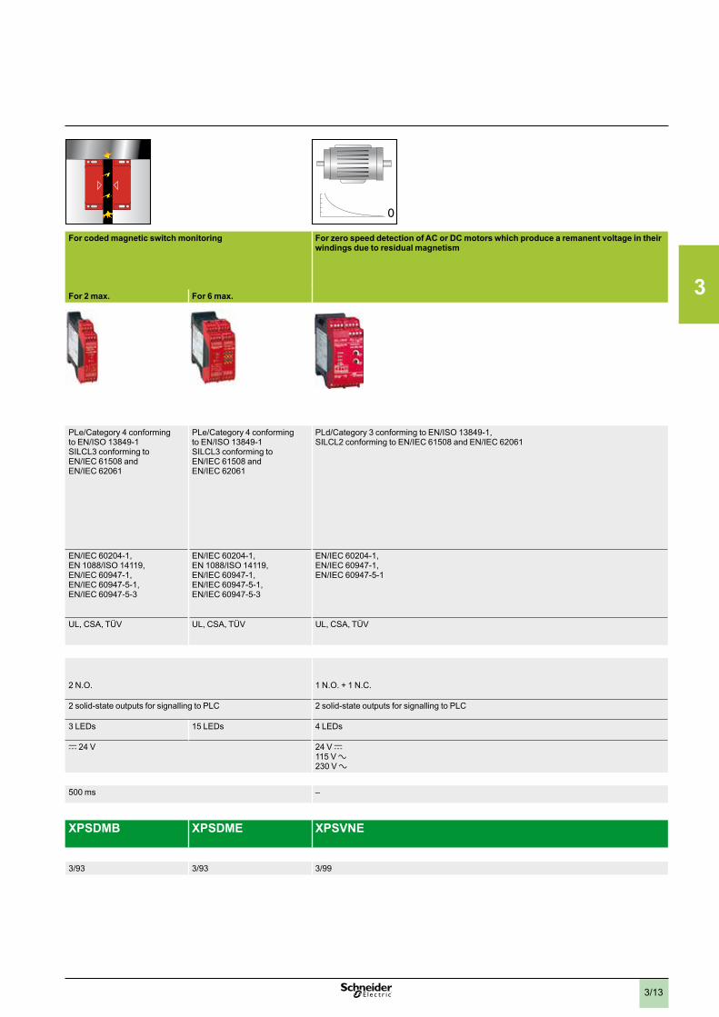
Modules For the monitoring of applications requiring safety time delays For coded magnetic switch monitoring For zero speed detection of AC or DC motors which produce a remanent voltage in their windings due to residual magnetism
For 2 max. For 6 max.
Maximum achievable safety level PLd/Category 3 conforming to EN/ISO 13849-1,SILCL2 conforming to EN/IEC 61508 and EN/IEC 62061
PLd/Category 3 conforming to EN/ISO 13849-1,SILCL2 conforming to EN/IEC 61508 and EN/IEC 62061
PLe/Category 4 conforming to EN/ISO 13849-1 SILCL3 conforming to EN/IEC 61508 and EN/IEC 62061
PLe/Category 4 conforming to EN/ISO 13849-1SILCL3 conforming to EN/IEC 61508 and EN/IEC 62061
PLd/Category 3 conforming to EN/ISO 13849-1, SILCL2 conforming to EN/IEC 61508 and EN/IEC 62061
Conformity to standards EN/IEC 60204-1,EN/IEC 60947-1,EN/IEC 60947-5-1
EN/IEC 60204-1,EN/IEC 60947-1,EN/IEC 60947-5-1
EN/IEC 60204-1,EN 1088/ISO 14119,EN/IEC 60947-1,EN/IEC 60947-5-1,EN/IEC 60947-5-3
EN/IEC 60204-1,EN 1088/ISO 14119,EN/IEC 60947-1,EN/IEC 60947-5-1,EN/IEC 60947-5-3
EN/IEC 60204-1,EN/IEC 60947-1,EN/IEC 60947-5-1
Product certifications UL, CSA, TÜV UL, CSA, TÜV UL, CSA, TÜV UL, CSA, TÜV UL, CSA, TÜV
Number of circuits
Safety 1 N.O. time delayed 1 N.O. pulse type 2 N.O. 1 N.O. + 1 N.C.
Additional 2 N.C. + 2 solid-state outputs for signalling to PLC 2 solid-state outputs for signalling to PLC 2 solid-state outputs for signalling to PLC
Display 4 LEDs 3 LEDs 15 LEDs 4 LEDs
Supply voltage a and 24 V c115 V a230 V a
c 24 V 24 V c115 V a230 V a
Synchronization time between inputs – – 500 ms –
Module type XPSTSA XPSTSW XPSDMB XPSDME XPSVNE
Pages 3/89 3/89 3/93 3/93 3/99
3
3/13
Applications
Modules For the monitoring of applications requiring safety time delays For coded magnetic switch monitoring For zero speed detection of AC or DC motors which produce a remanent voltage in their windings due to residual magnetism
For 2 max. For 6 max.
Maximum achievable safety level PLd/Category 3 conforming to EN/ISO 13849-1,SILCL2 conforming to EN/IEC 61508 and EN/IEC 62061
PLd/Category 3 conforming to EN/ISO 13849-1,SILCL2 conforming to EN/IEC 61508 and EN/IEC 62061
PLe/Category 4 conforming to EN/ISO 13849-1 SILCL3 conforming to EN/IEC 61508 and EN/IEC 62061
PLe/Category 4 conforming to EN/ISO 13849-1SILCL3 conforming to EN/IEC 61508 and EN/IEC 62061
PLd/Category 3 conforming to EN/ISO 13849-1, SILCL2 conforming to EN/IEC 61508 and EN/IEC 62061
Conformity to standards EN/IEC 60204-1,EN/IEC 60947-1,EN/IEC 60947-5-1
EN/IEC 60204-1,EN/IEC 60947-1,EN/IEC 60947-5-1
EN/IEC 60204-1,EN 1088/ISO 14119,EN/IEC 60947-1,EN/IEC 60947-5-1,EN/IEC 60947-5-3
EN/IEC 60204-1,EN 1088/ISO 14119,EN/IEC 60947-1,EN/IEC 60947-5-1,EN/IEC 60947-5-3
EN/IEC 60204-1,EN/IEC 60947-1,EN/IEC 60947-5-1
Product certifications UL, CSA, TÜV UL, CSA, TÜV UL, CSA, TÜV UL, CSA, TÜV UL, CSA, TÜV
Number of circuits
Safety 1 N.O. time delayed 1 N.O. pulse type 2 N.O. 1 N.O. + 1 N.C.
Additional 2 N.C. + 2 solid-state outputs for signalling to PLC 2 solid-state outputs for signalling to PLC 2 solid-state outputs for signalling to PLC
Display 4 LEDs 3 LEDs 15 LEDs 4 LEDs
Supply voltage a and 24 V c115 V a230 V a
c 24 V 24 V c115 V a230 V a
Synchronization time between inputs – – 500 ms –
Module type XPSTSA XPSTSW XPSDMB XPSDME XPSVNE
Pages 3/89 3/89 3/93 3/93 3/99
3
3/14
Selection guide (continued) Safety relaysPreventa™ safety relay modules
Applications
Modules
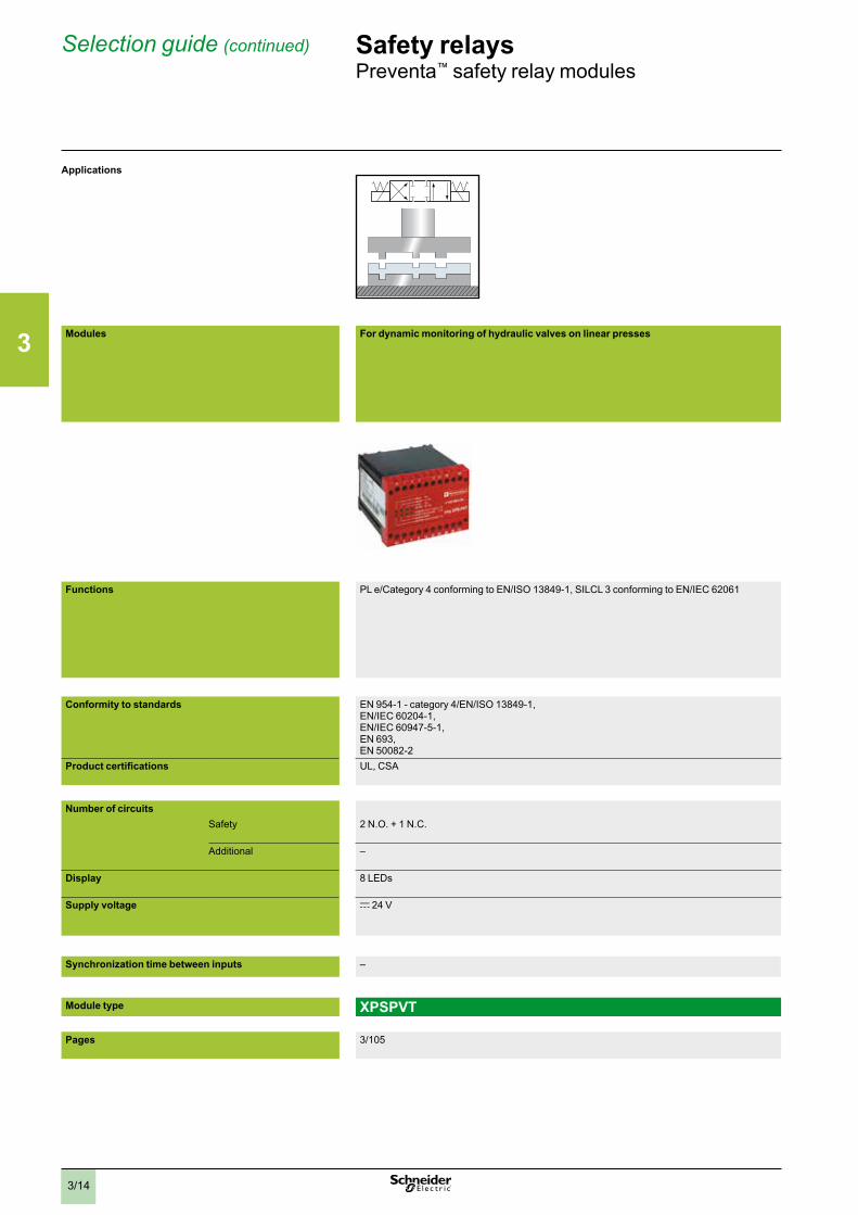
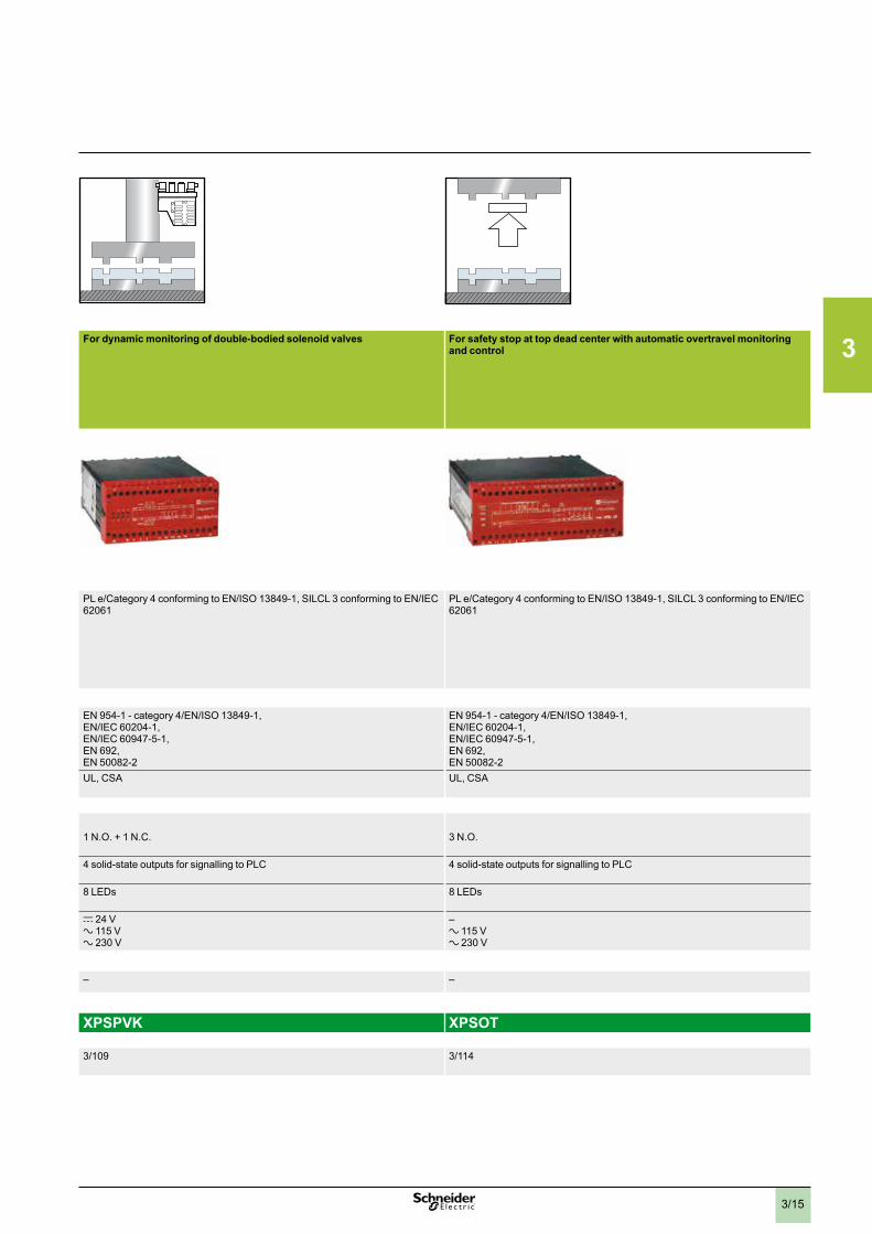
For dynamic monitoring of hydraulic valves on linear presses For dynamic monitoring of double-bodied solenoid valves For safety stop at top dead center with automatic overtravel monitoring and control
Functions PL e/Category 4 conforming to EN/ISO 13849-1, SILCL 3 conforming to EN/IEC 62061 PL e/Category 4 conforming to EN/ISO 13849-1, SILCL 3 conforming to EN/IEC 62061
PL e/Category 4 conforming to EN/ISO 13849-1, SILCL 3 conforming to EN/IEC 62061
Conformity to standards EN 954-1 - category 4/EN/ISO 13849-1,EN/IEC 60204-1,EN/IEC 60947-5-1,EN 693,EN 50082-2
EN 954-1 - category 4/EN/ISO 13849-1,EN/IEC 60204-1,EN/IEC 60947-5-1,EN 692,EN 50082-2
EN 954-1 - category 4/EN/ISO 13849-1,EN/IEC 60204-1,EN/IEC 60947-5-1,EN 692,EN 50082-2
Product certifications UL, CSA UL, CSA UL, CSA
Number of circuitsSafety 2 N.O. + 1 N.C. 1 N.O. + 1 N.C. 3 N.O.
Additional – 4 solid-state outputs for signalling to PLC 4 solid-state outputs for signalling to PLC
Display 8 LEDs 8 LEDs 8 LEDs
Supply voltage c 24 V c 24 Va 115 Va 230 V
–a 115 Va 230 V
Synchronization time between inputs – – –
Module type XPSPVT XPSPVK XPSOT
Pages 3/105 3/109 3/114
3
3/15
Applications
Modules
For dynamic monitoring of hydraulic valves on linear presses For dynamic monitoring of double-bodied solenoid valves For safety stop at top dead center with automatic overtravel monitoring and control
Functions PL e/Category 4 conforming to EN/ISO 13849-1, SILCL 3 conforming to EN/IEC 62061 PL e/Category 4 conforming to EN/ISO 13849-1, SILCL 3 conforming to EN/IEC 62061
PL e/Category 4 conforming to EN/ISO 13849-1, SILCL 3 conforming to EN/IEC 62061
Conformity to standards EN 954-1 - category 4/EN/ISO 13849-1,EN/IEC 60204-1,EN/IEC 60947-5-1,EN 693,EN 50082-2
EN 954-1 - category 4/EN/ISO 13849-1,EN/IEC 60204-1,EN/IEC 60947-5-1,EN 692,EN 50082-2
EN 954-1 - category 4/EN/ISO 13849-1,EN/IEC 60204-1,EN/IEC 60947-5-1,EN 692,EN 50082-2
Product certifications UL, CSA UL, CSA UL, CSA
Number of circuitsSafety 2 N.O. + 1 N.C. 1 N.O. + 1 N.C. 3 N.O.
Additional – 4 solid-state outputs for signalling to PLC 4 solid-state outputs for signalling to PLC
Display 8 LEDs 8 LEDs 8 LEDs
Supply voltage c 24 V c 24 Va 115 Va 230 V
–a 115 Va 230 V
Synchronization time between inputs – – –
Module type XPSPVT XPSPVK XPSOT
Pages 3/105 3/109 3/114
3
3/16
Electrical ratings Safety relaysPreventa™ safety relay modules
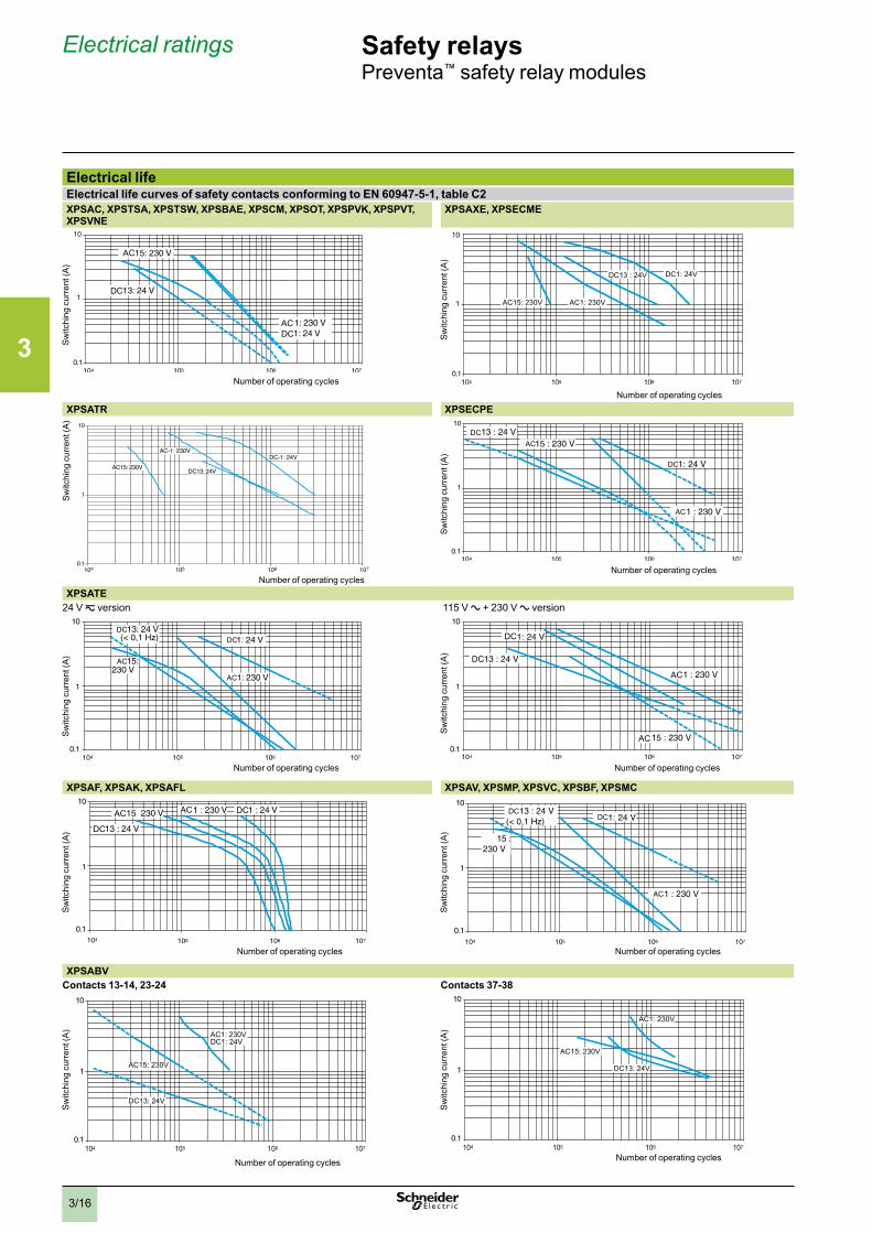
Electrical lifeElectrical life curves of safety contacts conforming to EN 60947-5-1, table C2XPSAC, XPSTSA, XPSTSW, XPSBAE, XPSCM, XPSOT, XPSPVK, XPSPVT, XPSVNE
XPSAXE, XPSECME
Sw
itchi
ng c
urre
nt (A
)
Number of operating cycles
1
10
Sw
itchi
ng c
urre
nt (A
)
Number of operating cycles
XPSATR XPSECPE
Sw
itchi
ng c
urre
nt (A
)
Number of operating cycles
XPSATE24 V z version 115 V a + 230 V a version
DCDC
Sw
itchi
ng c
urre
nt (A
)
Number of operating cycles
AC
DC
Sw
itchi
ng c
urre
nt (A
)
Number of operating cycles
XPSAF, XPSAK, XPSAFL XPSAV, XPSMP, XPSVC, XPSBF, XPSMC
DC
Number of operating cycles
Sw
itchi
ng c
urre
nt (A
)
Number of operating cycles
Sw
itchi
ng c
urre
nt (A
)
XPSABVContacts 13-14, 23-24 Contacts 37-38
Number of operating cycles
Sw
itchi
ng c
urre
nt (A
)
Number of operating cycles
Sw
itchi
ng c
urre
nt (A
)
Number of operating cycles
Sw
itchi
ng c
urre
nt (A
)
3
3/17
Electrical ratings (continued) Safety relaysPreventa™ safety relay modules
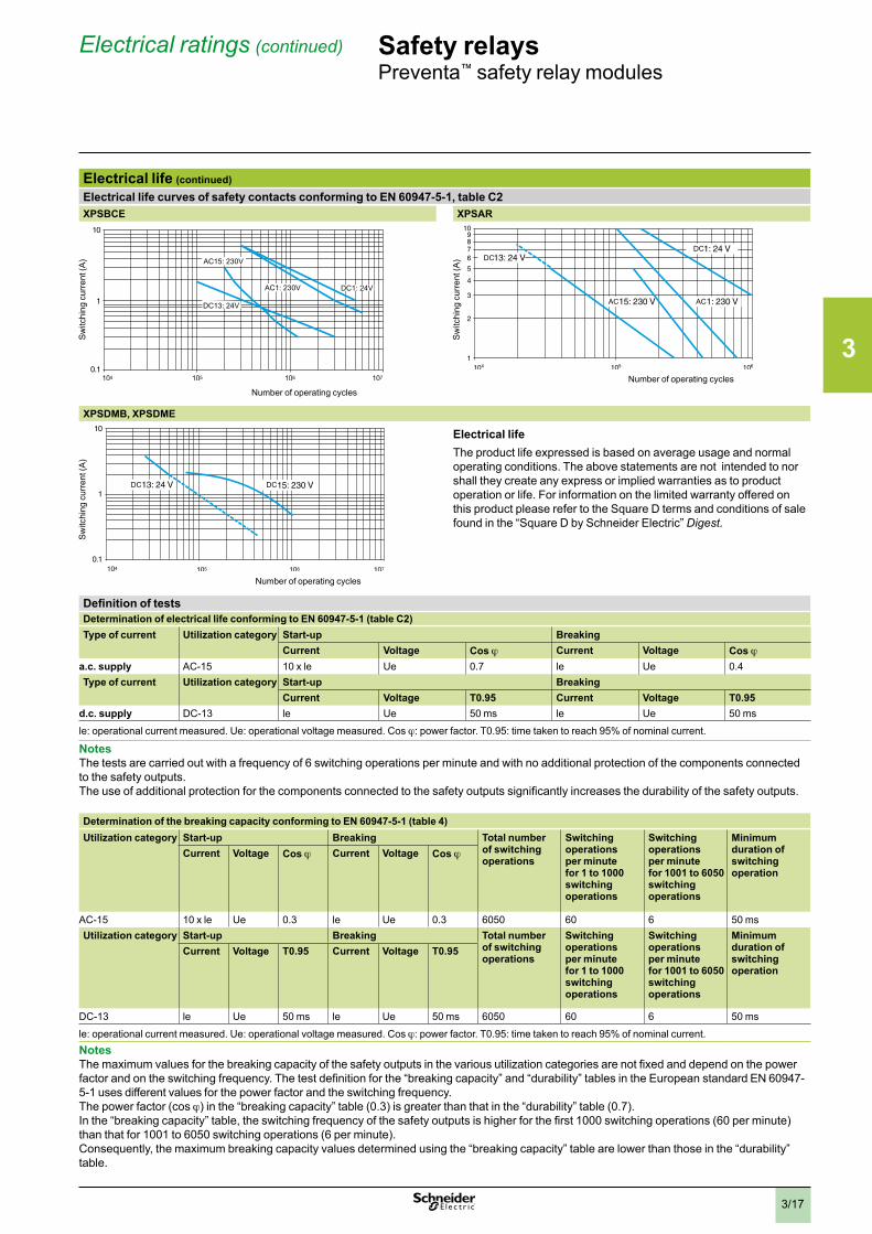
Electrical life (continued)Electrical life curves of safety contacts conforming to EN 60947-5-1, table C2XPSBCE XPSAR
Number of operating cycles
Sw
itchi
ng c
urre
nt (A
) DCDC
Number of operating cycles
Sw
itchi
ng c
urre
nt (A
)
XPSDMB, XPSDME
DC
Sw
itchi
ng c
urre
nt (A
)
Number of operating cycles
Electrical lifeThe product life expressed is based on average usage and normal operating conditions. The above statements are not intended to nor shall they create any express or implied warranties as to product operation or life. For information on the limited warranty offered on this product please refer to the Square D terms and conditions of sale found in the “Square D by Schneider Electric” Digest .
Definition of testsDetermination of electrical life conforming to EN 60947-5-1 (table C2)Type of current Utilization category Start-up Breaking
Current Voltage Cos j Current Voltage Cos ja.c. supply AC-15 10 x le Ue 0.7 le Ue 0.4Type of current Utilization category Start-up Breaking
Current Voltage T0.95 Current Voltage T0.95d.c. supply DC-13 le Ue 50 ms le Ue 50 ms
le: operational current measured. Ue: operational voltage measured. Cos j: power factor. T0.95: time taken to reach 95% of nominal current.
NotesThe tests are carried out with a frequency of 6 switching operations per minute and with no additional protection of the components connected to the safety outputs.The use of additional protection for the components connected to the safety outputs significantly increases the durability of the safety outputs.
Determination of the breaking capacity conforming to EN 60947-5-1 (table 4)Utilization category Start-up Breaking Total number
of switching operations
Switching operations per minute for 1 to 1000 switching operations
Switching operations per minute for 1001 to 6050 switching operations
Minimum duration of switching operation
Current Voltage Cos j Current Voltage Cos j
AC-15 10 x le Ue 0.3 le Ue 0.3 6050 60 6 50 msUtilization category Start-up Breaking Total number
of switching operations
Switching operations per minute for 1 to 1000 switching operations
Switching operations per minute for 1001 to 6050 switching operations
Minimum duration of switching operation
Current Voltage T0.95 Current Voltage T0.95
DC-13 le Ue 50 ms le Ue 50 ms 6050 60 6 50 ms
le: operational current measured. Ue: operational voltage measured. Cos j: power factor. T0.95: time taken to reach 95% of nominal current.NotesThe maximum values for the breaking capacity of the safety outputs in the various utilization categories are not fixed and depend on the power factor and on the switching frequency. The test definition for the “breaking capacity” and “durability” tables in the European standard EN 60947-5-1 uses different values for the power factor and the switching frequency.The power factor (cos j) in the “breaking capacity” table (0.3) is greater than that in the “durability” table (0.7).In the “breaking capacity” table, the switching frequency of the safety outputs is higher for the first 1000 switching operations (60 per minute) than that for 1001 to 6050 switching operations (6 per minute).Consequently, the maximum breaking capacity values determined using the “breaking capacity” table are lower than those in the “durability” table.
3
3/18
Safety relaysPreventa™ safety relay modules types XPSAC, XPSAXEFor Emergency stop and switch monitoring
Operating principle, specifications
Principle:page 3/18
Specifications:page 3/18
References:page 3/19
Wiring diagrams:page 3/20
Dimensions:page 3/116
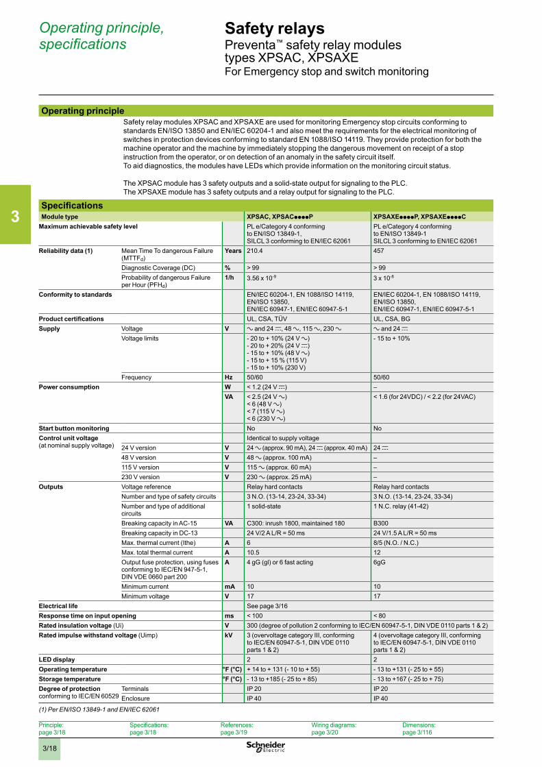
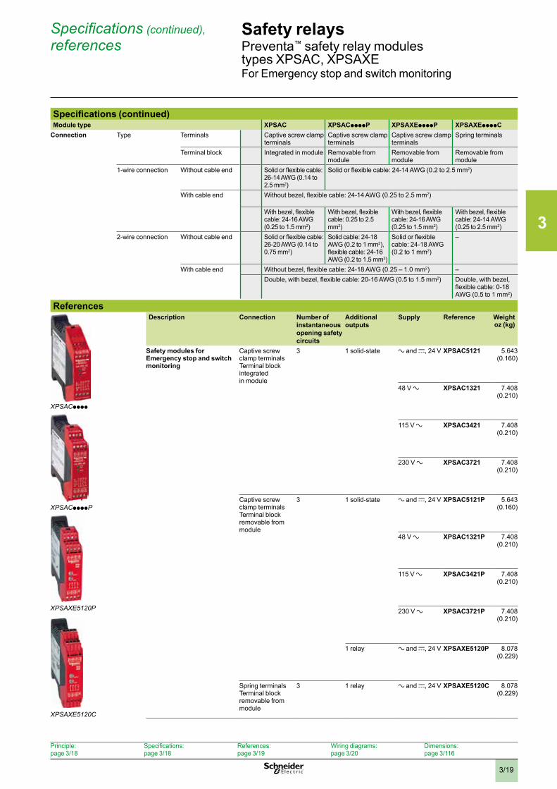
Operating principleSafety relay modules XPSAC and XPSAXE are used for monitoring Emergency stop circuits conforming to standards EN/ISO 13850 and EN/IEC 60204-1 and also meet the requirements for the electrical monitoring of switches in protection devices conforming to standard EN 1088/ISO 14119. They provide protection for both the machine operator and the machine by immediately stopping the dangerous movement on receipt of a stop instruction from the operator, or on detection of an anomaly in the safety circuit itself.To aid diagnostics, the modules have LEDs which provide information on the monitoring circuit status.
The XPSAC module has 3 safety outputs and a solid-state output for signaling to the PLC. The XPSAXE module has 3 safety outputs and a relay output for signaling to the PLC.
SpecificationsModule type XPSAC, XPSACppppP XPSAXEppppP, XPSAXEppppC
Maximum achievable safety level PL e/Category 4 conforming to EN/ISO 13849-1, SILCL 3 conforming to EN/IEC 62061
PL e/Category 4 conforming to EN/ISO 13849-1SILCL 3 conforming to EN/IEC 62061
Reliability data (1) Mean Time To dangerous Failure (MTTFd)
Years 210.4 457
Diagnostic Coverage (DC) % > 99 > 99Probability of dangerous Failure per Hour (PFHd)
1/h 3.56 x 10⁻⁹ 3 x 10⁻⁸
Conformity to standards EN/IEC 60204-1, EN 1088/ISO 14119,EN/ISO 13850, EN/IEC 60947-1, EN/IEC 60947-5-1
EN/IEC 60204-1, EN 1088/ISO 14119,EN/ISO 13850, EN/IEC 60947-1, EN/IEC 60947-5-1
Product certifications UL, CSA, TÜV UL, CSA, BGSupply Voltage V a and 24 c, 48 a, 115 a, 230 a a and 24 c
Voltage limits - 20 to + 10% (24 V a)- 20 to + 20% (24 V c)- 15 to + 10% (48 V a)- 15 to + 15 % (115 V)- 15 to + 10% (230 V)
- 15 to + 10%
Frequency Hz 50/60 50/60Power consumption W < 1.2 (24 V c) –
VA < 2.5 (24 V a)< 6 (48 V a)< 7 (115 V a)< 6 (230 V a)
< 1.6 (for 24VDC) / < 2.2 (for 24VAC)
Start button monitoring No NoControl unit voltage(at nominal supply voltage)
Identical to supply voltage24 V version V 24 a (approx. 90 mA), 24 c (approx. 40 mA) 24 c 48 V version V 48 a (approx. 100 mA) –115 V version V 115 a (approx. 60 mA) –230 V version V 230 a (approx. 25 mA) –
Outputs Voltage reference Relay hard contacts Relay hard contactsNumber and type of safety circuits 3 N.O. (13-14, 23-24, 33-34) 3 N.O. (13-14, 23-24, 33-34)Number and type of additional circuits
1 solid-state 1 N.C. relay (41-42)
Breaking capacity in AC-15 VA C300: inrush 1800, maintained 180 B300Breaking capacity in DC-13 24 V/2 A L/R = 50 ms 24 V/1.5 A L/R = 50 msMax. thermal current (Ithe) A 6 8/5 (N.O. / N.C.)Max. total thermal current A 10.5 12Output fuse protection, using fuses conforming to IEC/EN 947-5-1, DIN VDE 0660 part 200
A 4 gG (gl) or 6 fast acting 6gG
Minimum current mA 10 10Minimum voltage V 17 17
Electrical life See page 3/16Response time on input opening ms < 100 < 80Rated insulation voltage (Ui) V 300 (degree of pollution 2 conforming to IEC/EN 60947-5-1, DIN VDE 0110 parts 1 & 2)Rated impulse withstand voltage (Uimp) kV 3 (overvoltage category III, conforming
to IEC/EN 60947-5-1, DIN VDE 0110 parts 1 & 2)
4 (overvoltage category III, conforming to IEC/EN 60947-5-1, DIN VDE 0110 parts 1 & 2)
LED display 2 2Operating temperature °F (°C) + 14 to + 131 (- 10 to + 55) - 13 to +131 (- 25 to + 55)Storage temperature °F (°C) - 13 to +185 (- 25 to + 85) - 13 to +167 (- 25 to + 75)Degree of protection conforming to IEC/EN 60529
Terminals IP 20 IP 20Enclosure IP 40 IP 40
(1) Per EN/ISO 13849-1 and EN/IEC 62061
3
3/19
Safety relaysPreventa™ safety relay modules types XPSAC, XPSAXEFor Emergency stop and switch monitoring
Specifications (continued), references
Principle:page 3/18
Specifications:page 3/18
References:page 3/19
Wiring diagrams:page 3/20
Dimensions:page 3/116
Specifications (continued)Module type XPSAC XPSACppppP XPSAXEppppP XPSAXEppppC
Connection Type Terminals Captive screw clamp terminals
Captive screw clamp terminals
Captive screw clamp terminals
Spring terminals
Terminal block Integrated in module Removable from module
Removable from module
Removable from module
1-wire connection Without cable end Solid or flexible cable: 26-14 AWG (0.14 to 2.5 mm2)
Solid or flexible cable: 24-14 AWG (0.2 to 2.5 mm2)
With cable end Without bezel, flexible cable: 24-14 AWG (0.25 to 2.5 mm2)
With bezel, flexible cable: 24-16 AWG (0.25 to 1.5 mm2)
With bezel, flexible cable: 0.25 to 2.5 mm2)
With bezel, flexible cable: 24-16 AWG (0.25 to 1.5 mm2)
With bezel, flexible cable: 24-14 AWG (0.25 to 2.5 mm2)
2-wire connection Without cable end Solid or flexible cable: 26-20 AWG (0.14 to 0.75 mm2)
Solid cable: 24-18 AWG (0.2 to 1 mm2), flexible cable: 24-16 AWG (0.2 to 1.5 mm2)
Solid or flexible cable: 24-18 AWG (0.2 to 1 mm2)
–
With cable end Without bezel, flexible cable: 24-18 AWG (0.25 – 1.0 mm2) –Double, with bezel, flexible cable: 20-16 AWG (0.5 to 1.5 mm2) Double, with bezel,
flexible cable: 0-18 AWG (0.5 to 1 mm2)
ReferencesDescription Connection Number of
instantaneous opening safety circuits
Additional outputs
Supply Reference Weight oz (kg)
Safety modules for Emergency stop and switch monitoring
Captive screw clamp terminalsTerminal block integrated in module
3 1 solid-state a and c, 24 V XPSAC5121 5.643(0.160)
48 V a XPSAC1321 7.408 (0.210)
115 V a XPSAC3421 7.408 (0.210)
230 V a XPSAC3721 7.408 (0.210)
Captive screw clamp terminals Terminal block removable from module
3 1 solid-state a and c, 24 V XPSAC5121P 5.643(0.160)
48 V a XPSAC1321P 7.408 (0.210)
115 V a XPSAC3421P 7.408 (0.210)
230 V a XPSAC3721P 7.408 (0.210)
1 relay a and c, 24 V XPSAXE5120P 8.078 (0.229)
Spring terminalsTerminal block removable from module
3 1 relay a and c, 24 V XPSAXE5120C 8.078 (0.229)
XPSAXE5120P
XPSAXE5120C
XPSACppppP
XPSACpppp
3
3/20
Safety relaysPreventa™ safety relay modules type XPSACFor Emergency stop and switch monitoring
Wiring diagrams
Principle:page 3/18
Specifications:page 3/18
References:page 3/19
Wiring diagrams:page 3/20
Dimensions:page 3/116
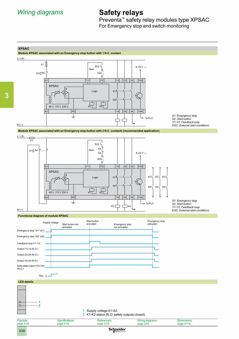
XPSACModule XPSAC associated with an Emergency stop button with 1 N.C. contact
Logic
To PLC
Start
S1: Emergency stopS2: Start buttonY1-Y2: Feedback loop .ESC: External start conditions .
Module XPSAC associated with an Emergency stop button with 2 N.C. contacts (recommended application)
S2
S1K3
K4
K3
K4
K3
K4
K3
K4
A1 23 33Y2 13
A2 PE 14 24 34
Y43
Y44
Y1
F1
K2K148 V, 115 V 230 V
K1
K2T
ESC
K4K3
XPSAC
Logic
To PLC
Start
S1: Emergency stopS2: Start buttonY1-Y2: Feedback loop .ESC: External start conditions .
Functional diagram of module XPSAC
Key
Emergency stop activatedEmergency stop
not activated
Supply voltage
Emergency stop "A2" (02)
Output 23-24 (N.O.)
Emergency stop "A1" (01)
Feedback loop Y1-Y2
Start button not activated
Output 13-14 (N.O.)
Output 33-34 (N.O.)
Solid-state output Y43-Y44 (N.O.)
Start button activated
01
LED details
Constituants pour applications de sécurité
Modules de sécurité PREVENTApour surveillance d'Arrêt d'urgence
XPS-ALSignification des DEL
XPSALDEL-ILL-2-B
12
1 Tension d'alimentation A1-A22 Etat de K1-K2
1 Supply voltage A1-A2.2 K1-K2 status (N.O. safety outputs closed).
3
3/21
Safety relaysPreventa™ safety relay modules type XPSAXEFor Emergency stop and switch monitoring
Wiring diagrams (continued)
Principle:page 3/18
Specifications:page 3/18
References:page 3/19
Wiring diagrams:page 3/20
Dimensions:page 3/116
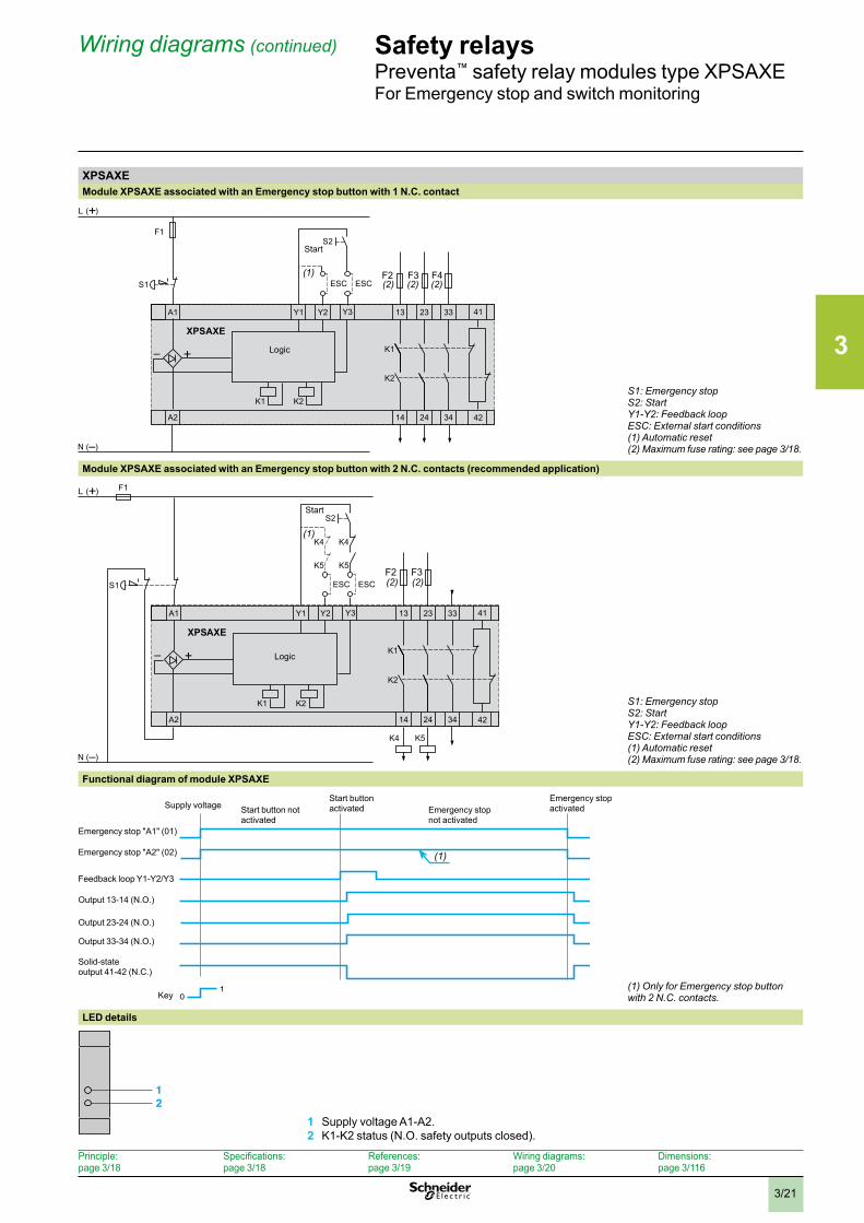
XPSAXEModule XPSAXE associated with an Emergency stop button with 1 N.C. contact
Logic
Start
S1: Emergency stopS2: StartY1-Y2: Feedback loopESC: External start conditions(1) Automatic reset(2) Maximum fuse rating: see page 3/18 .
Module XPSAXE associated with an Emergency stop button with 2 N.C. contacts (recommended application)
Logic
Start
S1: Emergency stopS2: StartY1-Y2: Feedback loopESC: External start conditions(1) Automatic reset(2) Maximum fuse rating: see page 3/18 .
Functional diagram of module XPSAXE
01
Emergency stop activatedEmergency stop
not activated
Supply voltage Start button not activated
Start button activated
Key
Emergency stop "A2" (02)
Output 23-24 (N.O.)
Emergency stop "A1" (01)
Feedback loop Y1-Y2/Y3
Output 13-14 (N.O.)
Output 33-34 (N.O.)
Solid-state output 41-42 (N.C.)
(1)
(1) Only for Emergency stop button with 2 N .C . contacts .
LED details
Constituants pour applications de sécurité
Modules de sécurité PREVENTApour surveillance d'Arrêt d'urgence
XPS-ALSignification des DEL
XPSALDEL-ILL-2-B
12
1 Tension d'alimentation A1-A22 Etat de K1-K2
1 Supply voltage A1-A2.2 K1-K2 status (N.O. safety outputs closed).
3
3/22
Operating principle, specifications
Safety relaysPreventa™ safety relay modules types XPSAV, XPSABV, XPSATEFor Emergency stop and switch monitoring
Principle: page 3/22
Specifications: page 3/22
References: page 3/24
Wiring diagrams: page 3/25
Dimensions:page 3/116
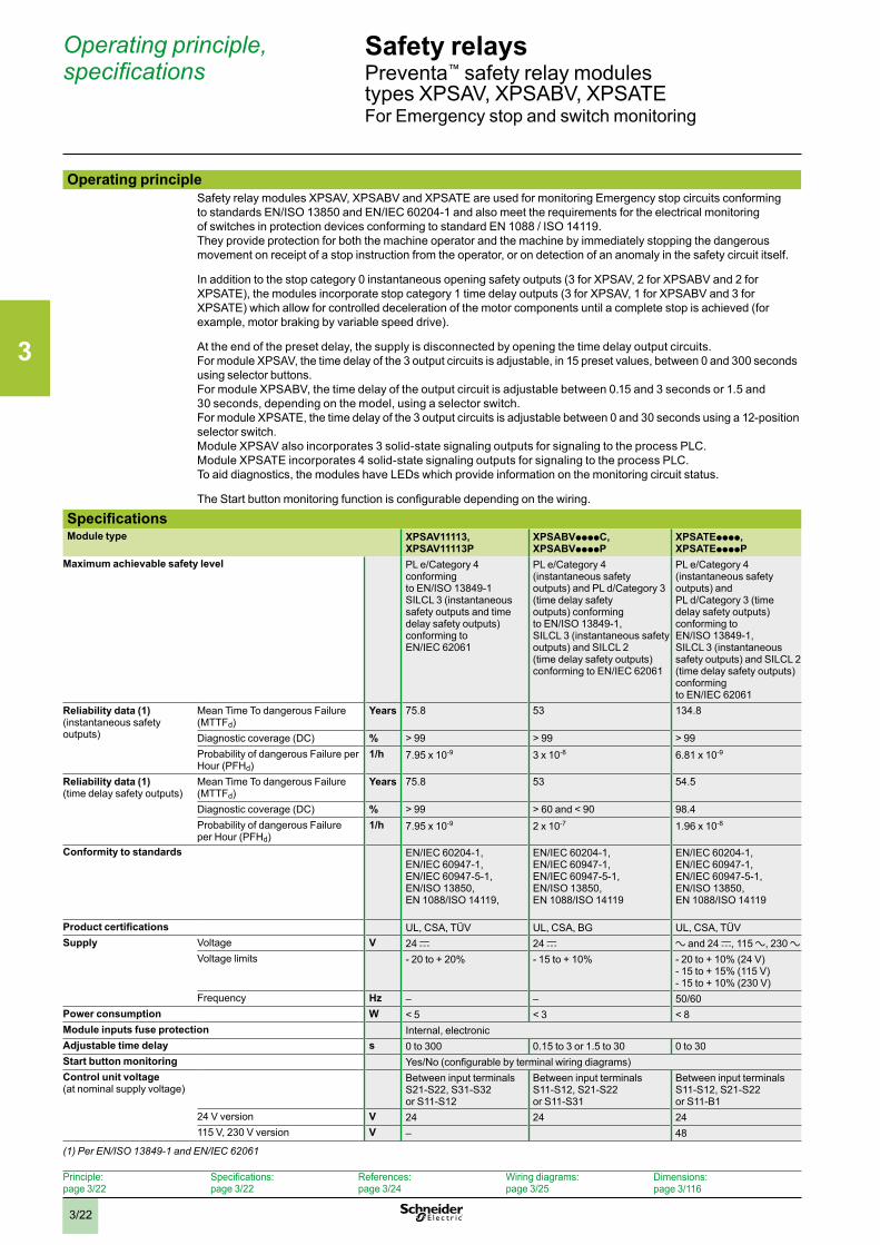
Operating principleSafety relay modules XPSAV, XPSABV and XPSATE are used for monitoring Emergency stop circuits conforming to standards EN/ISO 13850 and EN/IEC 60204-1 and also meet the requirements for the electrical monitoring of switches in protection devices conforming to standard EN 1088 / ISO 14119.They provide protection for both the machine operator and the machine by immediately stopping the dangerous movement on receipt of a stop instruction from the operator, or on detection of an anomaly in the safety circuit itself.
In addition to the stop category 0 instantaneous opening safety outputs (3 for XPSAV, 2 for XPSABV and 2 for XPSATE), the modules incorporate stop category 1 time delay outputs (3 for XPSAV, 1 for XPSABV and 3 for XPSATE) which allow for controlled deceleration of the motor components until a complete stop is achieved (for example, motor braking by variable speed drive).
At the end of the preset delay, the supply is disconnected by opening the time delay output circuits.For module XPSAV, the time delay of the 3 output circuits is adjustable, in 15 preset values, between 0 and 300 seconds using selector buttons.For module XPSABV, the time delay of the output circuit is adjustable between 0.15 and 3 seconds or 1.5 and 30 seconds, depending on the model, using a selector switch.For module XPSATE, the time delay of the 3 output circuits is adjustable between 0 and 30 seconds using a 12-position selector switch. Module XPSAV also incorporates 3 solid-state signaling outputs for signaling to the process PLC. Module XPSATE incorporates 4 solid-state signaling outputs for signaling to the process PLC.To aid diagnostics, the modules have LEDs which provide information on the monitoring circuit status.
The Start button monitoring function is configurable depending on the wiring.
SpecificationsModule type XPSAV11113,
XPSAV11113PXPSABVppppC,XPSABVppppP
XPSATEpppp, XPSATEppppP
Maximum achievable safety level PL e/Category 4 conforming to EN/ISO 13849-1 SILCL 3 (instantaneous safety outputs and time delay safety outputs) conforming to EN/IEC 62061
PL e/Category 4 (instantaneous safety outputs) and PL d/Category 3 (time delay safety outputs) conforming to EN/ISO 13849-1, SILCL 3 (instantaneous safety outputs) and SILCL 2 (time delay safety outputs) conforming to EN/IEC 62061
PL e/Category 4 (instantaneous safety outputs) and PL d/Category 3 (time delay safety outputs) conforming to EN/ISO 13849-1,SILCL 3 (instantaneous safety outputs) and SILCL 2 (time delay safety outputs) conforming to EN/IEC 62061
Reliability data (1)(instantaneous safety outputs)
Mean Time To dangerous Failure (MTTFd)
Years 75.8 53 134.8
Diagnostic coverage (DC) % > 99 > 99 > 99Probability of dangerous Failure per Hour (PFHd)
1/h 7.95 x 10⁻⁹ 3 x 10⁻⁸ 6.81 x 10⁻⁹
Reliability data (1)(time delay safety outputs)
Mean Time To dangerous Failure (MTTFd)
Years 75.8 53 54.5
Diagnostic coverage (DC) % > 99 > 60 and < 90 98.4Probability of dangerous Failure per Hour (PFHd)
1/h 7.95 x 10⁻⁹ 2 x 10⁻⁷ 1.96 x 10⁻⁸
Conformity to standards EN/IEC 60204-1,EN/IEC 60947-1,EN/IEC 60947-5-1,EN/ISO 13850,EN 1088/ISO 14119,
EN/IEC 60204-1,EN/IEC 60947-1, EN/IEC 60947-5-1, EN/ISO 13850,EN 1088/ISO 14119
EN/IEC 60204-1,EN/IEC 60947-1,EN/IEC 60947-5-1,EN/ISO 13850,EN 1088/ISO 14119
Product certifications UL, CSA, TÜV UL, CSA, BG UL, CSA, TÜVSupply Voltage V 24 c 24 c a and 24 c, 115 a, 230 a
Voltage limits - 20 to + 20% - 15 to + 10% - 20 to + 10% (24 V) - 15 to + 15% (115 V) - 15 to + 10% (230 V)
Frequency Hz – – 50/60Power consumption W < 5 < 3 < 8Module inputs fuse protection Internal, electronicAdjustable time delay s 0 to 300 0.15 to 3 or 1.5 to 30 0 to 30Start button monitoring Yes/No (configurable by terminal wiring diagrams)Control unit voltage(at nominal supply voltage)
Between input terminals S21-S22, S31-S32 or S11-S12
Between input terminals S11-S12, S21-S22 or S11-S31
Between input terminals S11-S12, S21-S22 or S11-B1
24 V version V 24 24 24115 V, 230 V version V – 48
(1) Per EN/ISO 13849-1 and EN/IEC 62061
3
3/23
Specifications (continued) Safety relaysPreventa™ safety relay modules types XPSAV, XPSABV, XPSATEFor Emergency stop and switch monitoring
Principle: page 3/22
Specifications: page 3/22
References: page 3/24
Wiring diagrams: page 3/25
Dimensions:page 3/116
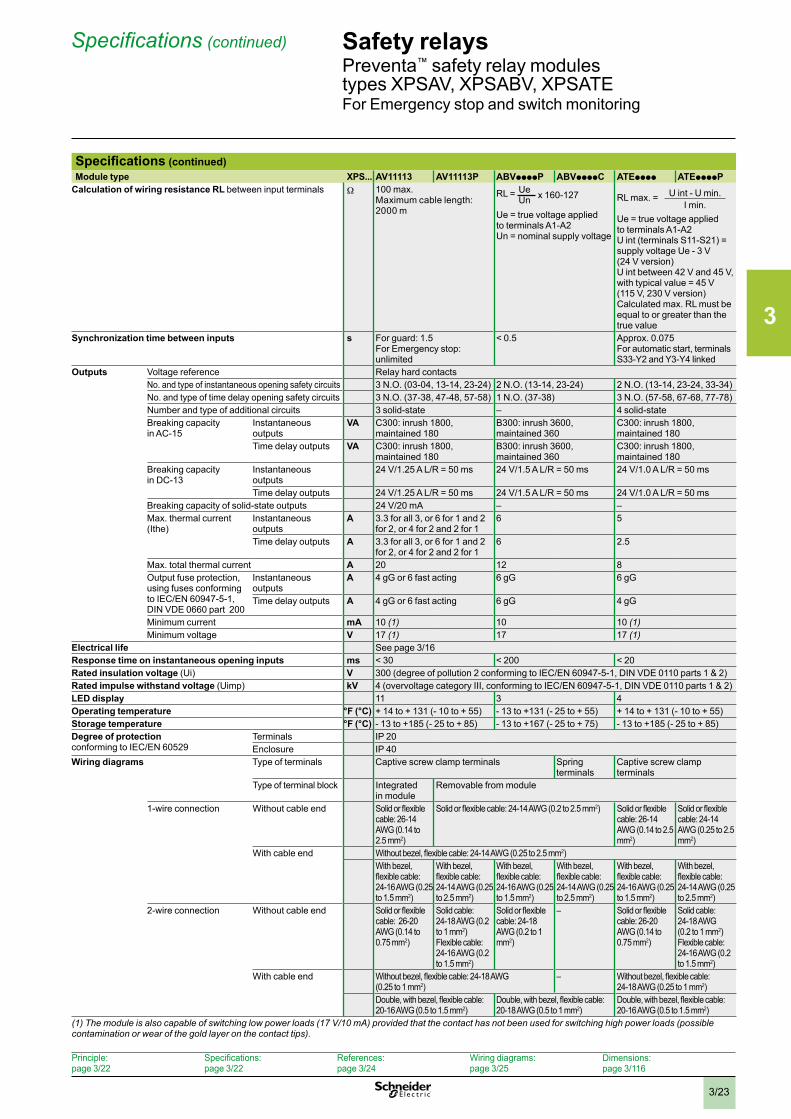
Specifications (continued)Module type XPS... AV11113 AV11113P ABVppppP ABVppppC ATEpppp ATEppppP
Calculation of wiring resistance RL between input terminals W 100 max.Maximum cable length: 2000 m
RL = UeUn x 160-127
Ue = true voltage applied to terminals A1-A2Un = nominal supply voltage
RL max. =
U int - U min.I min.
Ue = true voltage applied to terminals A1-A2 U int (terminals S11-S21) = supply voltage Ue - 3 V (24 V version) U int between 42 V and 45 V, with typical value = 45 V (115 V, 230 V version) Calculated max. RL must be equal to or greater than the true value
Synchronization time between inputs s For guard: 1.5For Emergency stop: unlimited
< 0.5 Approx. 0.075For automatic start, terminals S33-Y2 and Y3-Y4 linked
Outputs Voltage reference Relay hard contactsNo. and type of instantaneous opening safety circuits 3 N.O. (03-04, 13-14, 23-24) 2 N.O. (13-14, 23-24) 2 N.O. (13-14, 23-24, 33-34)No. and type of time delay opening safety circuits 3 N.O. (37-38, 47-48, 57-58) 1 N.O. (37-38) 3 N.O. (57-58, 67-68, 77-78)Number and type of additional circuits 3 solid-state – 4 solid-stateBreaking capacity in AC-15
Instantaneous outputs
VA C300: inrush 1800, maintained 180
B300: inrush 3600, maintained 360
C300: inrush 1800, maintained 180
Time delay outputs VA C300: inrush 1800, maintained 180
B300: inrush 3600, maintained 360
C300: inrush 1800, maintained 180
Breaking capacity in DC-13
Instantaneous outputs
24 V/1.25 A L/R = 50 ms 24 V/1.5 A L/R = 50 ms 24 V/1.0 A L/R = 50 ms
Time delay outputs 24 V/1.25 A L/R = 50 ms 24 V/1.5 A L/R = 50 ms 24 V/1.0 A L/R = 50 msBreaking capacity of solid-state outputs 24 V/20 mA – –Max. thermal current (Ithe)
Instantaneous outputs
A 3.3 for all 3, or 6 for 1 and 2 for 2, or 4 for 2 and 2 for 1
6 5
Time delay outputs A 3.3 for all 3, or 6 for 1 and 2 for 2, or 4 for 2 and 2 for 1
6 2.5
Max. total thermal current A 20 12 8Output fuse protection, using fuses conforming to IEC/EN 60947-5-1, DIN VDE 0660 part 200
Instantaneous outputs
A 4 gG or 6 fast acting 6 gG 6 gG
Time delay outputs A 4 gG or 6 fast acting 6 gG 4 gG
Minimum current mA 10 (1) 10 10 (1)Minimum voltage V 17 (1) 17 17 (1)
Electrical life See page 3/16Response time on instantaneous opening inputs ms < 30 < 200 < 20Rated insulation voltage (Ui) V 300 (degree of pollution 2 conforming to IEC/EN 60947-5-1, DIN VDE 0110 parts 1 & 2)Rated impulse withstand voltage (Uimp) kV 4 (overvoltage category III, conforming to IEC/EN 60947-5-1, DIN VDE 0110 parts 1 & 2)LED display 11 3 4Operating temperature °F (°C) + 14 to + 131 (- 10 to + 55) - 13 to +131 (- 25 to + 55) + 14 to + 131 (- 10 to + 55)Storage temperature °F (°C) - 13 to +185 (- 25 to + 85) - 13 to +167 (- 25 to + 75) - 13 to +185 (- 25 to + 85)Degree of protectionconforming to IEC/EN 60529
Terminals IP 20Enclosure IP 40
Wiring diagrams Type of terminals Captive screw clamp terminals Spring terminals
Captive screw clamp terminals
Type of terminal block Integrated in module
Removable from module
1-wire connection Without cable end Solid or flexible cable: 26-14 AWG (0.14 to 2.5 mm2)
Solid or flexible cable: 24-14 AWG (0.2 to 2.5 mm2) Solid or flexible cable: 26-14 AWG (0.14 to 2.5 mm2)
Solid or flexible cable: 24-14 AWG (0.25 to 2.5 mm2)
With cable end Without bezel, flexible cable: 24-14 AWG (0.25 to 2.5 mm2)With bezel, flexible cable: 24-16 AWG (0.25 to 1.5 mm2)
With bezel, flexible cable: 24-14 AWG (0.25 to 2.5 mm2)
With bezel, flexible cable: 24-16 AWG (0.25 to 1.5 mm2)
With bezel, flexible cable: 24-14 AWG (0.25 to 2.5 mm2)
With bezel, flexible cable: 24-16 AWG (0.25 to 1.5 mm2)
With bezel, flexible cable: 24-14 AWG (0.25 to 2.5 mm2)
2-wire connection Without cable end Solid or flexible cable: 26-20 AWG (0.14 to 0.75 mm2)
Solid cable: 24-18 AWG (0.2 to 1 mm2)Flexible cable: 24-16 AWG (0.2 to 1.5 mm2)
Solid or flexible cable: 24-18 AWG (0.2 to 1 mm2)
– Solid or flexible cable: 26-20 AWG (0.14 to 0.75 mm2)
Solid cable: 24-18 AWG (0.2 to 1 mm2)Flexible cable: 24-16 AWG (0.2 to 1.5 mm2)
With cable end Without bezel, flexible cable: 24-18 AWG (0.25 to 1 mm2)
– Without bezel, flexible cable: 24-18 AWG (0.25 to 1 mm2)
Double, with bezel, flexible cable: 20-16 AWG (0.5 to 1.5 mm2)
Double, with bezel, flexible cable: 20-18 AWG (0.5 to 1 mm2)
Double, with bezel, flexible cable: 20-16 AWG (0.5 to 1.5 mm2)
(1) The module is also capable of switching low power loads (17 V/10 mA) provided that the contact has not been used for switching high power loads (possible contamination or wear of the gold layer on the contact tips) .
3
3/24
References Safety relaysPreventa™ safety relay modules types XPSAV, XPSABV, XPSATEFor Emergency stop and switch monitoring
Principle: page 3/22
Specifications: page 3/22
References: page 3/24
Wiring diagrams: page 3/25
Dimensions:page 3/116
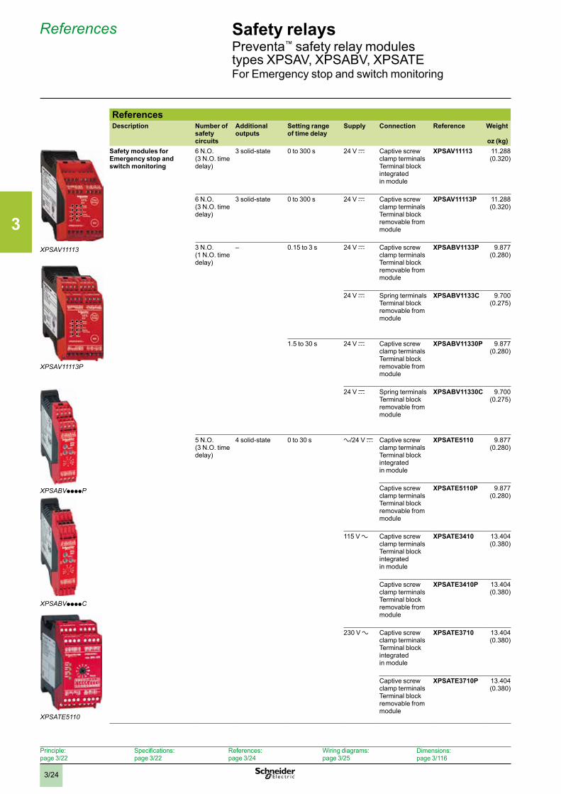
ReferencesDescription Number of
safety circuits
Additional outputs
Setting range of time delay
Supply Connection Reference Weight
oz (kg)Safety modules for Emergency stop and switch monitoring
6 N.O. (3 N.O. time delay)
3 solid-state 0 to 300 s 24 V c Captive screw clamp terminalsTerminal block integrated in module
XPSAV11113 11.288 (0.320)
6 N.O. (3 N.O. time delay)
3 solid-state 0 to 300 s 24 V c Captive screw clamp terminalsTerminal block removable from module
XPSAV11113P 11.288 (0.320)
3 N.O. (1 N.O. time delay)
– 0.15 to 3 s 24 V c Captive screw clamp terminalsTerminal block removable from module
XPSABV1133P 9.877 (0.280)
24 V c Spring terminals Terminal block removable from module
XPSABV1133C 9.700 (0.275)
1.5 to 30 s 24 V c Captive screw clamp terminalsTerminal block removable from module
XPSABV11330P 9.877 (0.280)
24 V c Spring terminals Terminal block removable from module
XPSABV11330C 9.700 (0.275)
5 N.O. (3 N.O. time delay)
4 solid-state 0 to 30 s a/24 V c Captive screw clamp terminalsTerminal block integrated in module
XPSATE5110 9.877 (0.280)
Captive screw clamp terminalsTerminal block removable from module
XPSATE5110P 9.877 (0.280)
115 V a Captive screw clamp terminalsTerminal block integrated in module
XPSATE3410 13.404 (0.380)
Captive screw clamp terminalsTerminal block removable from module
XPSATE3410P 13.404 (0.380)
230 V a Captive screw clamp terminalsTerminal block integrated in module
XPSATE3710 13.404 (0.380)
Captive screw clamp terminalsTerminal block removable from module
XPSATE3710P 13.404 (0.380)
XPSABVppppP
XPSABVppppC
XPSAV11113
XPSAV11113P
XPSATE5110
3
3/25
Wiring diagrams Safety relaysPreventa™ safety relay modules type XPSAVFor Emergency stop and switch monitoring
Principle: page 3/22
Specifications: page 3/22
References: page 3/24
Wiring diagrams: page 3/25
Dimensions:page 3/116
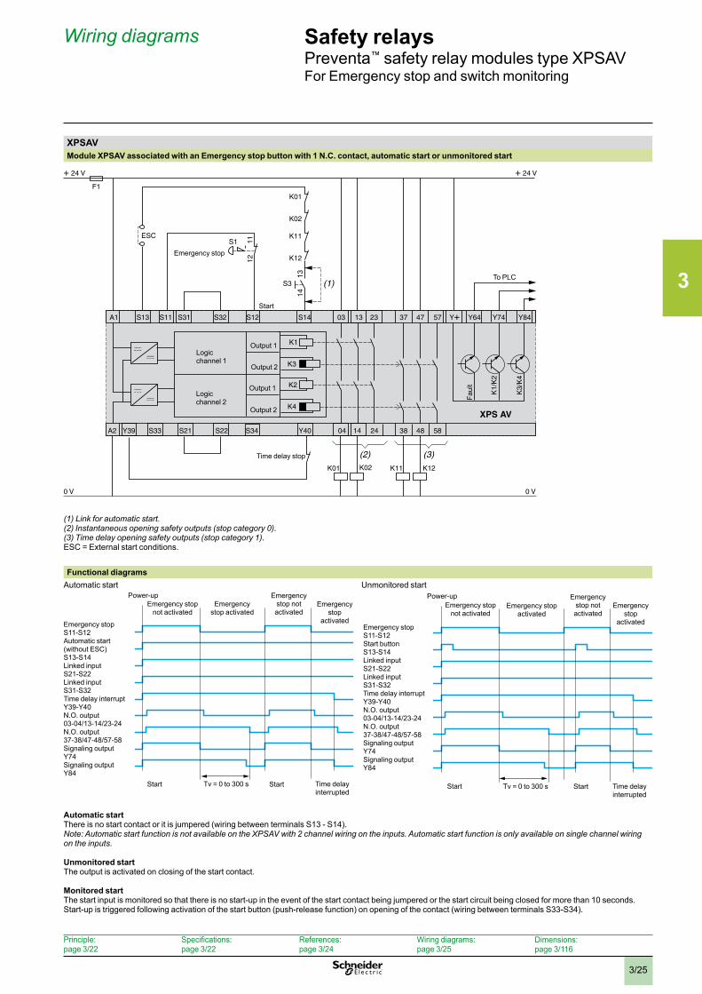
XPSAVModule XPSAV associated with an Emergency stop button with 1 N.C. contact, automatic start or unmonitored start
To PLC
Faul
t
Logicchannel 1
Logicchannel 2
Output 1
Output 2
Output 1
Output 2
Start
Time delay stop
Emergency stop
(1) Link for automatic start .(2) Instantaneous opening safety outputs (stop category 0) .(3) Time delay opening safety outputs (stop category 1) .ESC = External start conditions.
Functional diagramsAutomatic start Unmonitored start
Automatic startThere is no start contact or it is jumpered (wiring between terminals S13 - S14).Note: Automatic start function is not available on the XPSAV with 2 channel wiring on the inputs . Automatic start function is only available on single channel wiring on the inputs .
Unmonitored startThe output is activated on closing of the start contact.
Monitored startThe start input is monitored so that there is no start-up in the event of the start contact being jumpered or the start circuit being closed for more than 10 seconds.Start-up is triggered following activation of the start button (push-release function) on opening of the contact (wiring between terminals S33-S34).
Emergency stop S11-S12Automatic start (without ESC) S13-S14Linked input S21-S22Linked input S31-S32Time delay interrupt Y39-Y40N.O. output 03-04/13-14/23-24N.O. output 37-38/47-48/57-58Signaling output Y74Signaling output Y84
Emergency stop not activated
Power-upEmergency
stop activated
Emergency stop not activated
Emergency stop
activated
Start Start Time delay interrupted
Tv = 0 to 300 s
Emergency stop S11-S12Start button S13-S14Linked input S21-S22Linked input S31-S32Time delay interrupt Y39-Y40N.O. output 03-04/13-14/23-24N.O. output 37-38/47-48/57-58Signaling output Y74Signaling output Y84
Emergency stop not activated
Power-upEmergency stop
activatedEmergency
stop activated
Emergency stop not activated
Tv = 0 to 300 s Start Time delay interrupted
Start
3
3/26
Wiring diagrams (continued) Safety relaysPreventa™ safety relay modules type XPSAVFor Emergency stop and switch monitoring
Principle: page 3/22
Specifications: page 3/22
References: page 3/24
Wiring diagrams: page 3/25
Dimensions:page 3/116
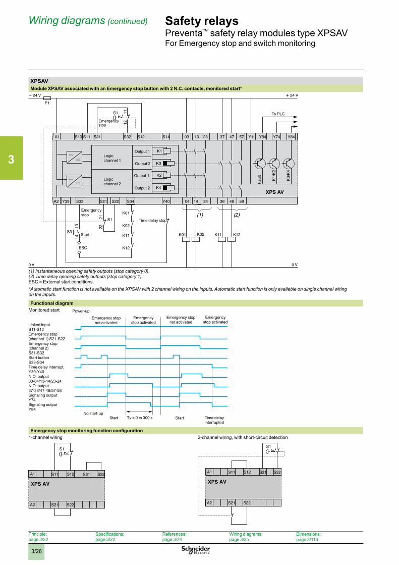
XPSAVModule XPSAV associated with an Emergency stop button with 2 N.C. contacts, monitored start*
(1) Instantaneous opening safety outputs (stop category 0) .(2) Time delay opening safety outputs (stop category 1) .ESC = External start conditions.*Automatic start function is not available on the XPSAV with 2 channel wiring on the inputs . Automatic start function is only available on single channel wiring on the inputs .
Functional diagramMonitored start
Emergency stop monitoring function configuration1-channel wiring 2-channel wiring, with short-circuit detection
XPS AV
S1
A1 S11 S31 S32
A2 S21 S22
S12
XPS AV
S1
A1 S11 S31 S32
A2 S21 S22
S12
To PLC
Faul
t
Logic channel 1
Logic channel 2
Output 1
Output 2
Output 1
Output 2
Time delay stop
Emergency stop
Emergency stop
Start
Emergency stop not activated
Power-up
Emergency stop activated
Emergency stop not activated
Emergency stop activated
Start Start Time delay interrupted
Tv = 0 to 300 sNo start-up
Linked input S11-S12Emergency stop (channel 1) S21-S22Emergency stop (channel 2) S31-S32Start button S33-S34Time delay interrupt Y39-Y40N.O. output 03-04/13-14/23-24N.O. output 37-38/47-48/57-58Signaling output Y74Signaling output Y84
3
3/27
Wiring diagrams (continued) Safety relaysPreventa™ safety relay modules type XPSAVFor Emergency stop and switch monitoring
Principle: page 3/22
Specifications: page 3/22
References: page 3/24
Wiring diagrams: page 3/25
Dimensions:page 3/116
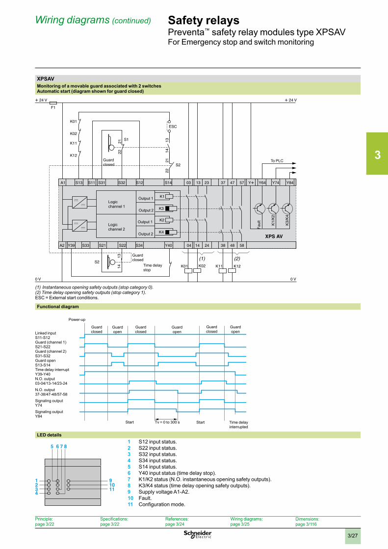
XPSAVMonitoring of a movable guard associated with 2 switches Automatic start (diagram shown for guard closed)
(1) Instantaneous opening safety outputs (stop category 0) .(2) Time delay opening safety outputs (stop category 1) .ESC = External start conditions.
Functional diagram
LED details 1 S12 input status.
2 S22 input status.3 S32 input status.4 S34 input status.5 S14 input status.6 Y40 input status (time delay stop).7 K1/K2 status (N.O. instantaneous opening safety outputs).8 K3/K4 status (time delay opening safety outputs).9 Supply voltage A1-A2.10 Fault.11 Configuration mode.
To PLC
Faul
t
Logicchannel 1
Logicchannel 2
Output 1
Output 2
Output 1
Output 2
Guardclosed
Guardclosed
Time delay stop
1
5 6 7 8
234
91011
Linked input S11-S12Guard (channel 1) S21-S22Guard (channel 2) S31-S32Guard open S13-S14Time delay interrupt Y39-Y40N.O. output 03-04/13-14/23-24N.O. output 37-38/47-48/57-58Signaling output Y74Signaling output Y84
Power-up
Guard closed
Guard open
Guard closed
Guard open
Guard closed
Guard open
Start Time delay interrupted
Start Tv = 0 to 300 s
3
3/28
Wiring diagrams (continued) Safety relaysPreventa™ safety relay modules type XPSABVFor Emergency stop and switch monitoring
Principle: page 3/22
Specifications: page 3/22
References: page 3/24
Wiring diagrams: page 3/25
Dimensions:page 3/116
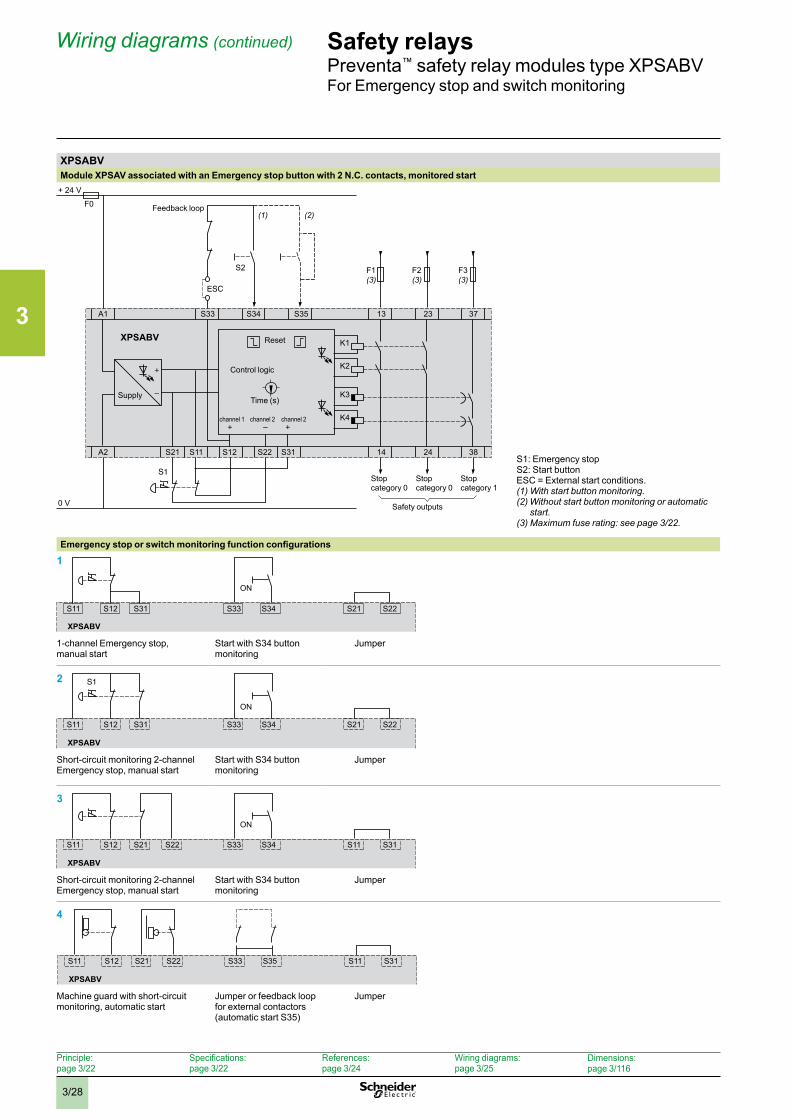
XPSABVModule XPSAV associated with an Emergency stop button with 2 N.C. contacts, monitored start
A1
+ 24 V
F0
F1(3)
(1) (2)
S2 F2(3)
F3(3)
0 V
K1
S33 S34 S35 13 23 37
A2 S21 S11 S12 S31S22 14 24 38
K2
K3
K4
XPSABV
Feedback loop
Stop category 0
Reset
channel 1 channel 2 channel 2
Time (s)
Control logic
Supply
Stop category 0
Stop category 1
Safety outputs
S1: Emergency stopS2: Start buttonESC = External start conditions.(1) With start button monitoring .(2) Without start button monitoring or automatic
start .(3) Maximum fuse rating: see page 3/22 .
Emergency stop or switch monitoring function configurations
S11 S12 S31 S33 S34 S21 S22
1
XPSABV
ON
1-channel Emergency stop, manual start
Start with S34 button monitoring
Jumper
XPSABV
S11 S12 S31 S33 S34 S21 S22
2
ON
Short-circuit monitoring 2-channel Emergency stop, manual start
Start with S34 button monitoring
Jumper
XPSABV
S11 S12 S21 S22 S33 S34 S11 S31
3
ON
Short-circuit monitoring 2-channel Emergency stop, manual start
Start with S34 button monitoring
Jumper
XPSABV
S11 S12 S21 S22 S33 S35 S11 S31
4
Machine guard with short-circuit monitoring, automatic start
Jumper or feedback loop for external contactors (automatic start S35)
Jumper
3
3/29
Wiring diagrams (continued) Safety relaysPreventa™ safety relay modules type XPSABVFor Emergency stop and switch monitoring
Principle: page 3/22
Specifications: page 3/22
References: page 3/24
Wiring diagrams: page 3/25
Dimensions:page 3/116
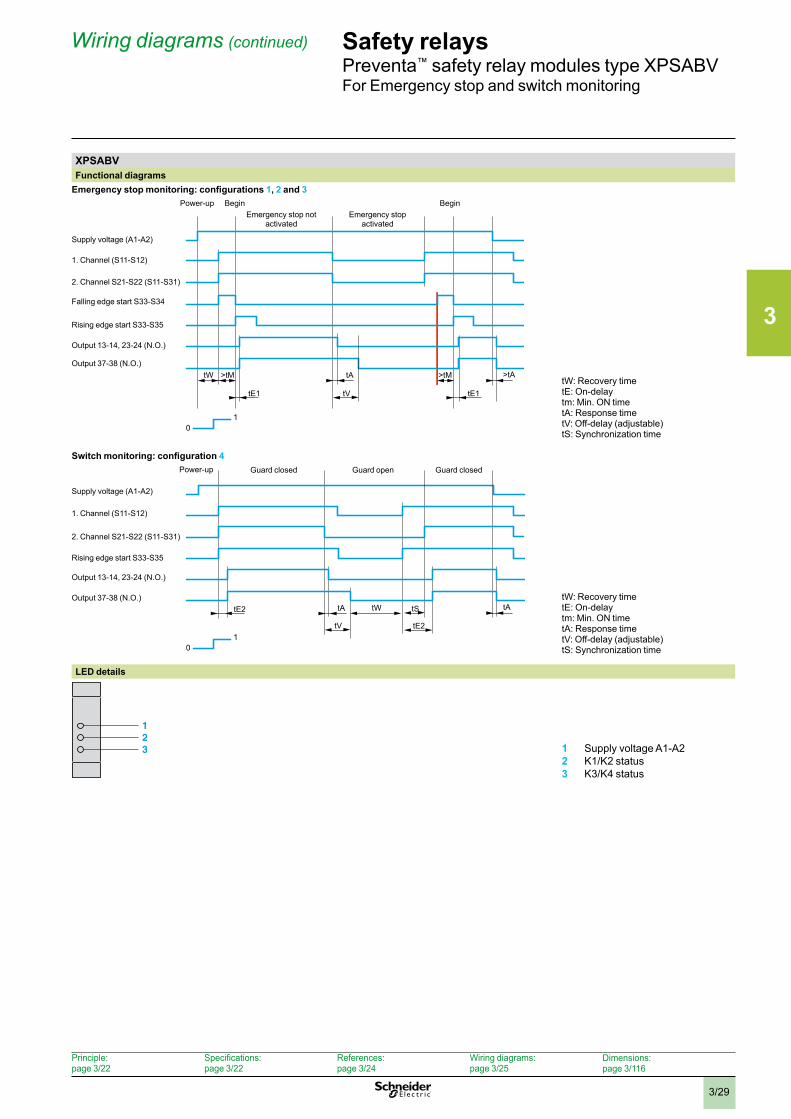
XPSABVFunctional diagrams
Emergency stop monitoring: configurations 1, 2 and 3 Power-up
Supply voltage (A1-A2)
tW
01
>tM >tM
tE1 tE1
tA >tA
tV
BeginEmergency stop not
activatedEmergency stop
activated
Begin
1. Channel (S11-S12)
2. Channel S21-S22 (S11-S31)
Falling edge start S33-S34
Rising edge start S33-S35
Output 13-14, 23-24 (N.O.)
Output 37-38 (N.O.)
tW: Recovery timetE: On-delaytm: Min. ON timetA: Response timetV: Off-delay (adjustable)tS: Synchronization time
Switch monitoring: configuration 4
tWtE2
tE2
tA tA
tV
tS
01
Supply voltage (A1-A2)
1. Channel (S11-S12)
2. Channel S21-S22 (S11-S31)
Rising edge start S33-S35
Output 13-14, 23-24 (N.O.)
Output 37-38 (N.O.)
Power-up Guard closed Guard open Guard closed
tW: Recovery timetE: On-delaytm: Min. ON timetA: Response timetV: Off-delay (adjustable)tS: Synchronization time
LED details
123 1 Supply voltage A1-A2
2 K1/K2 status3 K3/K4 status
3
3/30
Wiring diagrams (continued) Safety relaysPreventa™ safety relay modules type XPSATEFor Emergency stop and switch monitoring
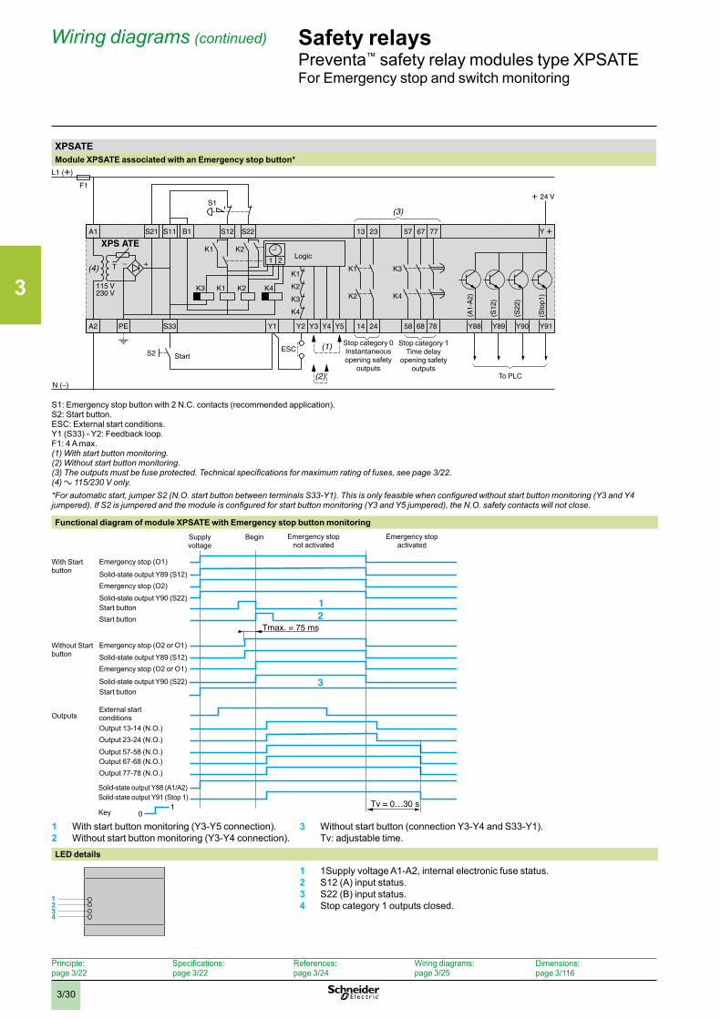
XPSATEModule XPSATE associated with an Emergency stop button*
Start
Logic
Stop category 0Instantaneous opening safety
outputs
Stop category 1Time delay
opening safety outputs
To PLC
S1: Emergency stop button with 2 N.C. contacts (recommended application).S2: Start button.ESC: External start conditions. Y1 (S33) - Y2: Feedback loop.F1: 4 A max.(1) With start button monitoring .(2) Without start button monitoring .(3) The outputs must be fuse protected. Technical specifications for maximum rating of fuses, see page 3/22 .(4) a 115/230 V only .*For automatic start, jumper S2 (N.O. start button between terminals S33-Y1). This is only feasible when configured without start button monitoring (Y3 and Y4 jumpered). If S2 is jumpered and the module is configured for start button monitoring (Y3 and Y5 jumpered), the N.O. safety contacts will not close.
Functional diagram of module XPSATE with Emergency stop button monitoring
1 With start button monitoring (Y3-Y5 connection).2 Without start button monitoring (Y3-Y4 connection).
3 Without start button (connection Y3-Y4 and S33-Y1). Tv: adjustable time.
LED details
1234
2
3
1
01 Tv = 0…30 s
Tmax. = 75 ms
Supply voltage
Begin Emergency stopactivated
Emergency stop not activated
Emergency stop (O1)
Key
With Start button Solid-state output Y89 (S12)
Emergency stop (O2)
Solid-state output Y90 (S22)Start buttonStart button
Emergency stop (O2 or O1)Without Start button Solid-state output Y89 (S12)
Emergency stop (O2 or O1)
Solid-state output Y90 (S22)Start button
External start conditionsOutputs
Output 13-14 (N.O.)Output 23-24 (N.O.)
Output 57-58 (N.O.)Output 67-68 (N.O.)Output 77-78 (N.O.)
Solid-state output Y88 (A1/A2)Solid-state output Y91 (Stop 1)
Principle: page 3/22
Specifications: page 3/22
References: page 3/24
Wiring diagrams: page 3/25
Dimensions:page 3/116
1 1Supply voltage A1-A2, internal electronic fuse status.2 S12 (A) input status.3 S22 (B) input status.4 Stop category 1 outputs closed.
3
3/31
Wiring diagrams (continued) Safety relaysPreventa™ safety relay modules type XPSATEFor Emergency stop and switch monitoring
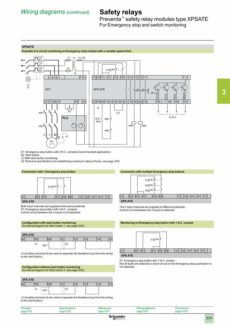
XPSATEExample of a circuit combining an Emergency stop module with a variable speed drive
S1: Emergency stop button with 2 N.C. contacts (recommended application).S2: Start button(1) With start button monitoring .(2) Technical specifications for establishing maximum rating of fuses, see page 3/22 .
Connection with 1 Emergency stop button Connection with multiple Emergency stop buttons
Both input channels are supplied at the same potential.S1: Emergency stop button with 2 N.C. contacts A short-circuit between the 2 inputs is not detected.
The 2 input channels are supplied at different potentials. A short-circuit between the 2 inputs is detected.
Configuration with start button monitoring(functional diagram for Start button 1, see page 3/25)
Monitoring an Emergency stop button with 1 N.C. contact
(1) Auxiliary terminal (to be used to separate the feedback loop from the wiring to the start button) .
S1: Emergency stop button with 1 N.C. contact.Not all faults are detected: a short-circuit on the Emergency stop pushbutton is not detected.Configuration without start button monitoring
(functional diagram for Start button 2, see page 3/25)
(1) Auxiliary terminal (to be used to separate the feedback loop from the wiring to the start button) .
StartPLC To PLC
S11S21A1 13 77S22B1 S12 23 57 67
S1
XPS ATE
S3
S11S21A1 13 77S22B1 S12 23 57 67
S2
S1
XPS ATE
S2
A2 PE S33 Y1 Y2 Y3 Y4 Y5
XPS ATE
(1)
S11S21A1 13 67 77S22B1 S12 23 57
S1
XPS ATE
A2 PE S33 Y1 Y2 Y3 Y4 Y5
XPS ATE
S2 (1)
Principle: page 3/22
Specifications: page 3/22
References: page 3/24
Wiring diagrams: page 3/25
Dimensions:page 3/116
3
3/32
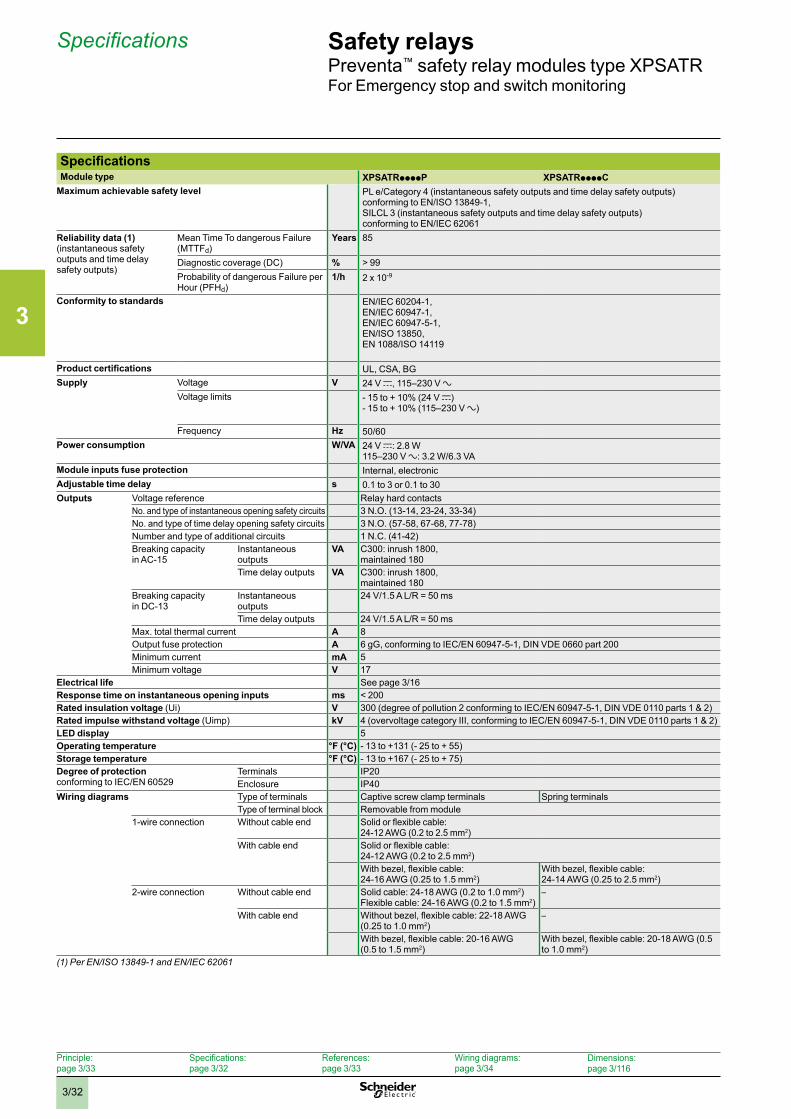
Specifications Safety relaysPreventa™ safety relay modules type XPSATRFor Emergency stop and switch monitoring
Outputs Voltage reference Relay hard contactsNo. and type of instantaneous opening safety circuits 3 N.O. (13-14, 23-24, 33-34)No. and type of time delay opening safety circuits 3 N.O. (57-58, 67-68, 77-78)Number and type of additional circuits 1 N.C. (41-42)Breaking capacity in AC-15
Instantaneous outputs
VA C300: inrush 1800,maintained 180
Time delay outputs VA C300: inrush 1800,maintained 180
Breaking capacity in DC-13
Instantaneous outputs
24 V/1.5 A L/R = 50 ms
Time delay outputs 24 V/1.5 A L/R = 50 msMax. total thermal current A 8Output fuse protection A 6 gG, conforming to IEC/EN 60947-5-1, DIN VDE 0660 part 200Minimum current mA 5Minimum voltage V 17
Electrical life See page 3/16Response time on instantaneous opening inputs ms < 200Rated insulation voltage (Ui) V 300 (degree of pollution 2 conforming to IEC/EN 60947-5-1, DIN VDE 0110 parts 1 & 2)Rated impulse withstand voltage (Uimp) kV 4 (overvoltage category III, conforming to IEC/EN 60947-5-1, DIN VDE 0110 parts 1 & 2)LED display 5Operating temperature °F (°C) - 13 to +131 (- 25 to + 55)Storage temperature °F (°C) - 13 to +167 (- 25 to + 75)Degree of protectionconforming to IEC/EN 60529
Terminals IP20Enclosure IP40
Wiring diagrams Type of terminals Captive screw clamp terminals Spring terminalsType of terminal block Removable from module
1-wire connection Without cable end Solid or flexible cable: 24-12 AWG (0.2 to 2.5 mm2)
With cable end Solid or flexible cable: 24-12 AWG (0.2 to 2.5 mm2)With bezel, flexible cable: 24-16 AWG (0.25 to 1.5 mm2)
With bezel, flexible cable: 24-14 AWG (0.25 to 2.5 mm2)
2-wire connection Without cable end Solid cable: 24-18 AWG (0.2 to 1.0 mm2)Flexible cable: 24-16 AWG (0.2 to 1.5 mm2)
–
With cable end Without bezel, flexible cable: 22-18 AWG (0.25 to 1.0 mm2)
–
With bezel, flexible cable: 20-16 AWG (0.5 to 1.5 mm2)
With bezel, flexible cable: 20-18 AWG (0.5 to 1.0 mm2)
(1) Per EN/ISO 13849-1 and EN/IEC 62061
SpecificationsModule type XPSATRppppP XPSATRppppC
Maximum achievable safety level PL e/Category 4 (instantaneous safety outputs and time delay safety outputs) conforming to EN/ISO 13849-1, SILCL 3 (instantaneous safety outputs and time delay safety outputs) conforming to EN/IEC 62061
Reliability data (1)(instantaneous safety outputs and time delay safety outputs)
Mean Time To dangerous Failure (MTTFd)
Years 85
Diagnostic coverage (DC) % > 99Probability of dangerous Failure per Hour (PFHd)
1/h 2 x 10⁻⁹
Conformity to standards EN/IEC 60204-1,EN/IEC 60947-1, EN/IEC 60947-5-1, EN/ISO 13850,EN 1088/ISO 14119
Product certifications UL, CSA, BGSupply Voltage V 24 V c, 115–230 V a
Voltage limits - 15 to + 10% (24 V c)- 15 to + 10% (115–230 V a)
Frequency Hz 50/60Power consumption W/VA 24 V c: 2.8 W
115–230 V a: 3.2 W/6.3 VAModule inputs fuse protection Internal, electronicAdjustable time delay s 0.1 to 3 or 0.1 to 30
Principle: page 3/33
Specifications: page 3/32
References: page 3/33
Wiring diagrams: page 3/34
Dimensions:page 3/116
3
3/33
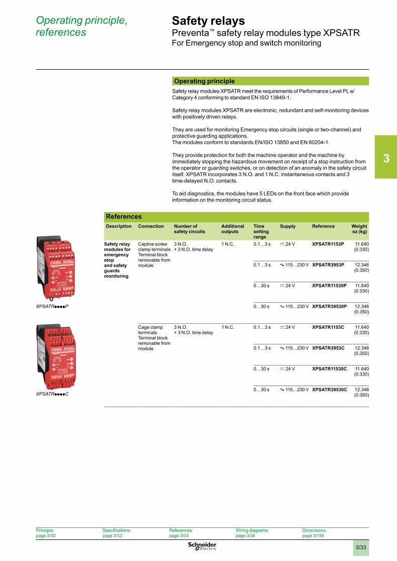
Operating principle, references
Safety relaysPreventa™ safety relay modules type XPSATRFor Emergency stop and switch monitoring
Operating principleSafety relay modules XPSATR meet the requirements of Performance Level PL e/Category 4 conforming to standard EN ISO 13849-1.
Safety relay modules XPSATR are electronic, redundant and self-monitoring devices with positively driven relays.
They are used for monitoring Emergency stop circuits (single or two-channel) and protective guarding applications. The modules conform to standards EN/ISO 13850 and EN 60204-1.
They provide protection for both the machine operator and the machine by immediately stopping the hazardous movement on receipt of a stop instruction from the operator or guarding switches, or on detection of an anomaly in the safety circuit itself. XPSATR incorporates 3 N.O. and 1 N.C. instantaneous contacts and 3 time-delayed N.O. contacts.
To aid diagnostics, the modules have 5 LEDs on the front face which provide information on the monitoring circuit status.
ReferencesDescription Connection Number of
safety circuitsAdditional outputs
Time setting range
Supply Reference Weightoz (kg)
Safety relay modules for emergency stop and safety guards monitoring
Captive screw clamp terminals Terminal block removable from module
3 N.O. + 3 N.O. time delay
1 N.C. 0.1…3 s c 24 V XPSATR1153P 11.640 (0.330)
0.1…3 s a 115…230 V XPSATR3953P 12.346 (0.350)
0…30 s c 24 V XPSATR11530P 11.640 (0.330)
0…30 s a 115…230 V XPSATR39530P 12.346 (0.350)
Cage clamp terminals Terminal block removable from module
3 N.O. + 3 N.O. time delay
1 N.C. 0.1…3 s c 24 V XPSATR1153C 11.640 (0.330)
0.1…3 s a 115…230 V XPSATR3953C 12.346 (0.350)
0…30 s c 24 V XPSATR11530C 11.640 (0.330)
0…30 s a 115…230 V XPSATR39530C 12.346 (0.350)
XPSATRppppP
XPSATRppppC
Principle: page 3/33
Specifications: page 3/32
References: page 3/33
Wiring diagrams: page 3/34
Dimensions:page 3/116
3
3/34
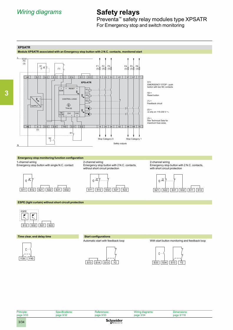
Wiring diagrams Safety relaysPreventa™ safety relay modules type XPSATRFor Emergency stop and switch monitoring
XPSATRModule XPSATR associated with an Emergency stop button with 2 N.C. contacts, monitored start
Emergency stop monitoring function configuration1-channel wiring Emergency stop button with single N.C. contact
2-channel wiring Emergency stop button with 2 N.C. contacts, without short circuit protection
2-channel wiring Emergency stop button with 2 N.C. contacts, with short circuit protection
ESPE (light curtain) without short circuit protection
Time clear, end delay time Start configurationsAutomatic start with feedback loop With start button monitoring and feedback loop
XPS-ATR
A1
SUPPLY
+
–
CONTROL LOGIC
13
14
23
24
33
34
41
42
57
58
67
68
77
78
TIMECLEAR
+
+EDM
+ +RESET
+CH1 CH2
+–
K2
K5
K3
K4
A1
K1
Time [s]
F1(3)
F2(3)
F3(3)
F4(3)
F5(3)
F6(3)
F0L
(3)
N
t
S21 S22 S13 Y2 S14 S11 S12
A2A2 S33 S34 Y40 S31 S32
S1
S1
S2
(1)
(2)
S11 S12 S21 S22 S31 S32
S11 S12 S32 S21 S22
S21 S22 S31 S32 S11 S12
S12 S32 S21 S22
ESPE
S13 S14 S13 Y2
S33 S34 S13 Y2
Y39 Y40
S1=EMERGENCY STOP - push button with two NC contacts
S2 =Reset button
(1) =Feedback circuit
(2) =t only on 115-230 V a
(3) =See Technical Data for maximum fuse sizes.
Stop Category 0 Stop Category 1
Safety outputs
XPS-ATR
A1
SUPPLY
+
–
CONTROL LOGIC
13
14
23
24
33
34
41
42
57
58
67
68
77
78
TIMECLEAR
+
+EDM
+ +RESET
+CH1 CH2
+–
K2
K5
K3
K4
A1
K1
Time [s]
F1(3)
F2(3)
F3(3)
F4(3)
F5(3)
F6(3)
F0L
(3)
N
t
S21 S22 S13 Y2 S14 S11 S12
A2A2 S33 S34 Y40 S31 S32
S1
S1
S2
(1)
(2)
S11 S12 S21 S22 S31 S32
S11 S12 S32 S21 S22
S21 S22 S31 S32 S11 S12
S12 S32 S21 S22
ESPE
S13 S14 S13 Y2
S33 S34 S13 Y2
Y39 Y40
S1=EMERGENCY STOP - push button with two NC contacts
S2 =Reset button
(1) =Feedback circuit
(2) =t only on 115-230 V a
(3) =See Technical Data for maximum fuse sizes.
Stop Category 0 Stop Category 1
Safety outputsXPS-ATR
A1
SUPPLY
+
–
CONTROL LOGIC
13
14
23
24
33
34
41
42
57
58
67
68
77
78
TIMECLEAR
+
+EDM
+ +RESET
+CH1 CH2
+–
K2
K5
K3
K4
A1
K1
Time [s]
F1(3)
F2(3)
F3(3)
F4(3)
F5(3)
F6(3)
F0L
(3)
N
t
S21 S22 S13 Y2 S14 S11 S12
A2A2 S33 S34 Y40 S31 S32
S1
S1
S2
(1)
(2)
S11 S12 S21 S22 S31 S32
S11 S12 S32 S21 S22
S21 S22 S31 S32 S11 S12
S12 S32 S21 S22
ESPE
S13 S14 S13 Y2
S33 S34 S13 Y2
Y39 Y40
S1=EMERGENCY STOP - push button with two NC contacts
S2 =Reset button
(1) =Feedback circuit
(2) =t only on 115-230 V a
(3) =See Technical Data for maximum fuse sizes.
Stop Category 0 Stop Category 1
Safety outputs
XPS-ATR
A1
SUPPLY
+
–
CONTROL LOGIC
13
14
23
24
33
34
41
42
57
58
67
68
77
78
TIMECLEAR
+
+EDM
+ +RESET
+CH1 CH2
+–
K2
K5
K3
K4
A1
K1
Time [s]
F1(3)
F2(3)
F3(3)
F4(3)
F5(3)
F6(3)
F0L
(3)
N
t
S21 S22 S13 Y2 S14 S11 S12
A2A2 S33 S34 Y40 S31 S32
S1
S1
S2
(1)
(2)
S11 S12 S21 S22 S31 S32
S11 S12 S32 S21 S22
S21 S22 S31 S32 S11 S12
S12 S32 S21 S22
ESPE
S13 S14 S13 Y2
S33 S34 S13 Y2
Y39 Y40
S1=EMERGENCY STOP - push button with two NC contacts
S2 =Reset button
(1) =Feedback circuit
(2) =t only on 115-230 V a
(3) =See Technical Data for maximum fuse sizes.
Stop Category 0 Stop Category 1
Safety outputs
Principle: page 3/33
Specifications: page 3/32
References: page 3/33
Wiring diagrams: page 3/34
Dimensions:page 3/116
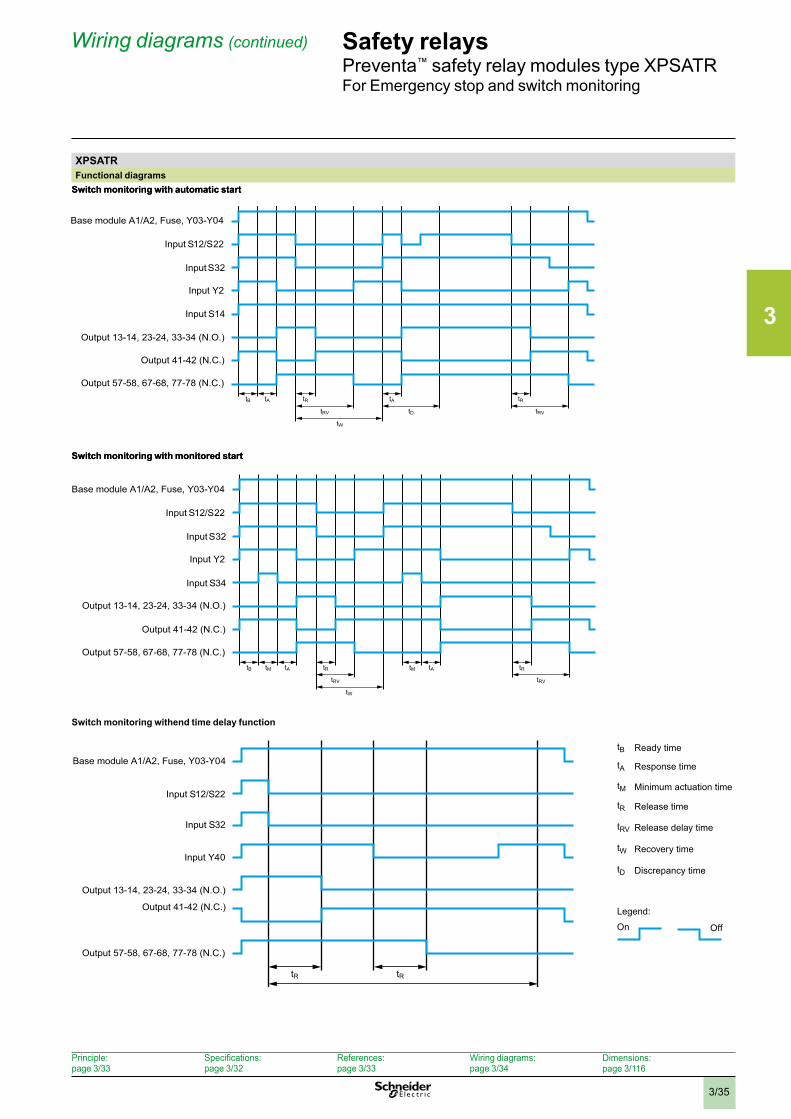
3
3/35
XPSATRFunctional diagrams
Switch monitoring with automatic start
Switch monitoring with monitored start
Wiring diagrams (continued) Safety relaysPreventa™ safety relay modules type XPSATRFor Emergency stop and switch monitoring
XPSATRFunctional diagrams
Switch monitoring with automatic start
Switch monitoring with monitored start
Switch monitoring withend time delay function
tB tA tR
tRV tD tRV
tW
tA tR
tB tM tA tR
tRV tRV
tW
tM tA tR
tR tR
Base module A1/A2, Fuse, Y03-Y04
Input S12/S22
Input S32
Input Y2
Input S14
Output 13-14, 23-24, 33-34 (N.O.)
Output 41-42 (N.C.)
Output 57-58, 67-68, 77-78 (N.C.)
Base module A1/A2, Fuse, Y03-Y04
Input S12/S22
Input S32
Input Y2
Input S34
Output 13-14, 23-24, 33-34 (N.O.)
Output 41-42 (N.C.)
Output 57-58, 67-68, 77-78 (N.C.)
Base module A1/A2, Fuse, Y03-Y04
Input S12/S22
Input S32
Input Y40
Output 13-14, 23-24, 33-34 (N.O.)
Output 41-42 (N.C.)
Output 57-58, 67-68, 77-78 (N.C.)
tB Ready time
tA Response time
tM Minimum actuation time
tR Release time
tRV Release delay time
tW Recovery time
tD Discrepancy time
On Off
Legend:
Principle: page 3/33
Specifications: page 3/32
References: page 3/33
Wiring diagrams: page 3/34
Dimensions:page 3/116
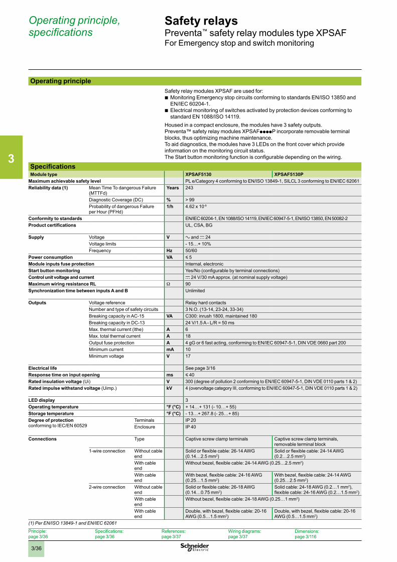
3
3/36
Safety relaysPreventa™ safety relay modules type XPSAFFor Emergency stop and switch monitoring
Operating principleSafety relay modules XPSAF are used for:
b Monitoring Emergency stop circuits conforming to standards EN/ISO 13850 and EN/IEC 60204-1.
b Electrical monitoring of switches activated by protection devices conforming to standard EN 1088/ISO 14119.
Housed in a compact enclosure, the modules have 3 safety outputs.Preventa™ safety relay modules XPSAFppppP incorporate removable terminal blocks, thus optimizing machine maintenance. To aid diagnostics, the modules have 3 LEDs on the front cover which provide information on the monitoring circuit status.The Start button monitoring function is configurable depending on the wiring.
SpecificationsModule type XPSAF5130 XPSAF5130P
Maximum achievable safety level PL e/Category 4 conforming to EN/ISO 13849-1, SILCL 3 conforming to EN/IEC 62061Reliability data (1) Mean Time To dangerous Failure
(MTTFd)Years 243
Diagnostic Coverage (DC) % > 99Probability of dangerous Failure per Hour (PFHd)
1/h 4.62 x 10⁻⁹
Conformity to standards EN/IEC 60204-1, EN 1088/ISO 14119, EN/IEC 60947-5-1, EN/ISO 13850, EN 50082-2Product certifications UL, CSA, BG
Supply Voltage V a and c 24Voltage limits - 15…+ 10%Frequency Hz 50/60
Power consumption VA y 5Module inputs fuse protection Internal, electronicStart button monitoring Yes/No (configurable by terminal connections)Control unit voltage and current c 24 V/30 mA approx. (at nominal supply voltage)Maximum wiring resistance RL W 90Synchronization time between inputs A and B Unlimited
Outputs Voltage reference Relay hard contactsNumber and type of safety circuits 3 N.O. (13-14, 23-24, 33-34)Breaking capacity in AC-15 VA C300: inrush 1800, maintained 180Breaking capacity in DC-13 24 V/1.5 A - L/R = 50 msMax. thermal current (Ithe) A 6Max. total thermal current A 18Output fuse protection A 4 gG or 6 fast acting, conforming to EN/IEC 60947-5-1, DIN VDE 0660 part 200Minimum current mA 10Minimum voltage V 17
Electrical life See page 3/16Response time on input opening ms y 40Rated insulation voltage (Ui) V 300 (degree of pollution 2 conforming to EN/IEC 60947-5-1, DIN VDE 0110 parts 1 & 2)Rated impulse withstand voltage (Uimp.) kV 4 (overvoltage category III, conforming to EN/IEC 60947-5-1, DIN VDE 0110 parts 1 & 2)
LED display 3Operating temperature °F (°C) + 14…+ 131 (- 10…+ 55)Storage temperature °F (°C) - 13…+ 267.8 (- 25…+ 85)Degree of protection conforming to IEC/EN 60529
Terminals IP 20Enclosure IP 40
Connections Type Captive screw clamp terminals Captive screw clamp terminals, removable terminal block
1-wire connection Without cable end
Solid or flexible cable: 26-14 AWG (0.14…2.5 mm2)
Solid or flexible cable: 24-14 AWG (0.2…2.5 mm2)
With cable end
Without bezel, flexible cable: 24-14 AWG (0.25…2.5 mm2)
With cable end
With bezel, flexible cable: 24-16 AWG (0.25…1.5 mm2)
With bezel, flexible cable: 24-14 AWG (0.25…2.5 mm2)
2-wire connection Without cable end
Solid or flexible cable: 26-18 AWG (0.14…0.75 mm2)
Solid cable: 24-18 AWG (0.2…1 mm2), flexible cable: 24-16 AWG (0.2…1.5 mm2)
With cable end
Without bezel, flexible cable: 24-18 AWG (0.25…1 mm2)
With cable end
Double, with bezel, flexible cable: 20-16 AWG (0.5…1.5 mm2)
Double, with bezel, flexible cable: 20-16 AWG (0.5…1.5 mm2)
(1) Per EN/ISO 13849-1 and EN/IEC 62061
Operating principle, specifications
Principle: page 3/36
Specifications: page 3/36
References: page 3/37
Wiring diagrams: page 3/37
Dimensions:page 3/116
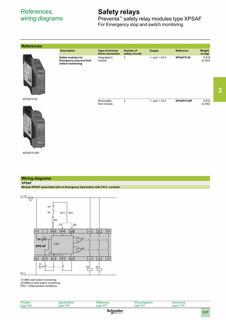
3
3/37
Safety relaysPreventa™ safety relay modules type XPSAFFor Emergency stop and switch monitoring
ReferencesDescription Type of terminal
block connectionNumber of safety circuits
Supply Reference Weightoz (kg)
Safety modules for Emergency stop and limit switch monitoring
Integrated in module
3 a and c 24 V
XPSAF5130 8.818 (0.250)
Removable from module
3 a and c 24 V XPSAF5130P 8.818 (0.250)
Wiring diagramsXPSAFModule XPSAF associated with an Emergency stop button with 2 N.C. contacts
(1) With start button monitoring .(2) Without start button monitoring .ESC = External start conditions.
XPSAF5130
XPSAF5130P
F1
L1 (+)
N (–)
TK1
K2
S1
A1 33
A2
S34S33 S39
XPS AF
S22S21S12 14 24S11 34
2313
S2
K3
K4
ESC
K4K3
(1) (2)
Start
Logic
References, wiring diagrams
Principle: page 3/36
Specifications: page 3/36
References: page 3/37
Wiring diagrams: page 3/37
Dimensions:page 3/116
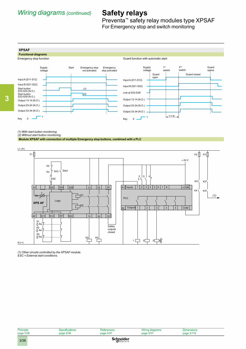
3
3/38
Safety relaysPreventa™ safety relay modules type XPSAFFor Emergency stop and switch monitoring
XPSAFFunctional diagrams
Emergency stop function Guard function with automatic start
(1) With start button monitoring .(2) Without start button monitoring .Module XPSAF with connection of multiple Emergency stop buttons, combined with a PLC
(1) Other circuits controlled by the XPSAF module . ESC = External start conditions .
1
(1)
(2)
Supply voltage
Emergency stop activated
Emergency stop not activated
Start
Input A (S11-S12)
Input B (S21-S22)
Start button S33-S39 (N.O.)
Output 23-24 (N.O.)
Output 13-14 (N.O.)
Output 33-34 (N.O.)
Key 0
Start button S33-S34 (N.O.)
1 t =
Supply voltage
Input A (S11-S12)
Input B (S21-S22)
Link at S33-S39
Output 23-24 (N.O.)
Output 13-14 (N.O.)
Output 33-34 (N.O.)
Key 0
Guard open
1st
switch2nd switch
Guard closed
Guard opens
F1
L1 (+)
N (–)
TK1
K2
A1 33
A2
S34S33 S39
XPS AF
S22S21S12 14 24S11 34
2313
S4
K3
K4
ESC
K4K32 31
1 43 5 +COM
COM321
2
F3
K3
K4
3 42
(1)
S1
S2
S3
F2
+ 24 V
A1
A2
76 8
4 5
K3
K4
Inputs
Outputs
PLCLogic
Safety outputs closed
Start
Wiring diagrams (continued)
Principle: page 3/36
Specifications: page 3/36
References: page 3/37
Wiring diagrams: page 3/37
Dimensions:page 3/116
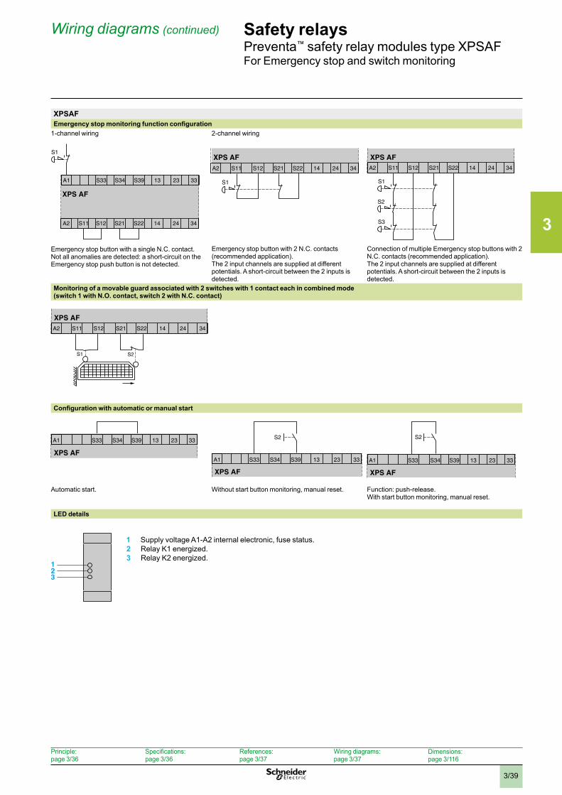
3
3/39
Safety relaysPreventa™ safety relay modules type XPSAFFor Emergency stop and switch monitoring
XPSAFEmergency stop monitoring function configuration
1-channel wiring
Emergency stop button with a single N.C. contact.Not all anomalies are detected: a short-circuit on the Emergency stop push button is not detected.
2-channel wiring
Emergency stop button with 2 N.C. contacts (recommended application).The 2 input channels are supplied at different potentials. A short-circuit between the 2 inputs is detected.
Connection of multiple Emergency stop buttons with 2 N.C. contacts (recommended application).The 2 input channels are supplied at different potentials. A short-circuit between the 2 inputs is detected.
Monitoring of a movable guard associated with 2 switches with 1 contact each in combined mode(switch 1 with N.O. contact, switch 2 with N.C. contact)
Configuration with automatic or manual start
Automatic start. Without start button monitoring, manual reset. Function: push-release.With start button monitoring, manual reset.
LED details 1 Supply voltage A1-A2 internal electronic, fuse status. 2 Relay K1 energized. 3 Relay K2 energized.
XPS AF
S1
A1 S33 S34 S39 13 23 33
A2 S11 S12 S21 S22 14 24 34
XPS AF
S1
A2 S11 S12 S21 S22 14 24 34
S1
S2
S3
XPS AFA2 S11 S12 S21 S22 14 24 34
S1 S2
XPS AFA2 S11 S12 S21 S22 14 24 34
XPS AF
A1 S33 S34 S39 13 23 33
XPS AF
S2
A1 S33 S34 S39 13 23 33
XPS AF
S2
A1 S33 S34 S39 13 23 33
123
Wiring diagrams (continued)
Principle: page 3/36
Specifications: page 3/36
References: page 3/37
Wiring diagrams: page 3/37
Dimensions:page 3/116
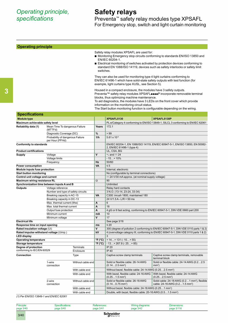
3
3/40
Operating principle, specifications
Safety relaysPreventa™ safety relay modules type XPSAFLFor Emergency stop, switch and light curtain monitoring
Operating principleSafety relay modules XPSAFL are used for:
b Monitoring Emergency stop circuits conforming to standards EN/ISO 13850 and EN/IEC 60204-1.
b Electrical monitoring of switches activated by protection devices conforming to standard EN 1088/ISO 14119, devices such as safety interlocks or safety limit switches.
They can also be used for monitoring type 4 light curtains conforming to EN/IEC 61496-1 which have solid-state safety outputs with test function (for example, light curtains type XUSL, see Section 5).
Housed in a compact enclosure, the modules have 3 safety outputs.Preventa™ safety relay modules XPSAFLppppP incorporate removable terminal blocks, thus optimizing machine maintenance.To aid diagnostics, the modules have 3 LEDs on the front cover which provide information on the monitoring circuit status.The Start button monitoring function is configurable depending on the wiring.
SpecificationsModule type XPSAFL5130 XPSAFL5130P
Maximum achievable safety level PL e/Category 4 conforming to EN/ISO 13849-1, SILCL 3 conforming to EN/IEC 62061Reliability data (1) Mean Time To dangerous Failure
(MTTFd)Years 172.1
Diagnostic Coverage (DC) % > 99Probability of dangerous Failure per Hour (PFHd)
1/h 5.61 x 10⁻⁹
Conformity to standards EN/IEC 60204-1, EN 1088/ISO 14119, EN/IEC 60947-5-1, EN/ISO 13850, EN 50082-2, EN/IEC 61496-1 (type 4)
Product certifications UL, CSA, BGSupply Voltage V a and c 24
Voltage limits - 15…+ 10%Frequency Hz 50/60
Power consumption VA y 5Module inputs fuse protection Internal, electronicStart button monitoring No (configurable by terminal connections)Control unit voltage and current c 24 V/30 mA approx. (at nominal supply voltage)Maximum wiring resistance RL W 90Synchronization time between inputs A and B UnlimitedOutputs Voltage reference Relay hard contacts
Number and type of safety circuits 3 N.O. (13-14, 23-24, 33-34)Breaking capacity in AC-15 VA C300: inrush 1800, maintained 180Breaking capacity in DC-13 24 V/1.5 A - L/R = 50 msMax. thermal current (Ithe) A 6Max. total thermal current A 18Output fuse protection A 4 gG or 6 fast acting, conforming to EN/IEC 60947-5-1, DIN VDE 0660 part 200Minimum current mA 10Minimum voltage V 17
Electrical life See page 3/16Response time on input opening ms y 20Rated insulation voltage (Ui) V 300 (degree of pollution 2 conforming to EN/IEC 60947-5-1, DIN VDE 0110 parts 1 & 2)Rated impulse withstand voltage (Uimp.) kV 4 (overvoltage category III, conforming to EN/IEC 60947-5-1, DIN VDE 0110 parts 1 & 2)LED display 3Operating temperature °F (°C) + 14…+ 131 (- 10…+ 55)Storage temperature °F (°C) - 13…+ 267.8 (- 25…+ 85)Degree of protection conforming to IEC/EN 60529
Terminals IP 20Enclosure IP 40
Connection Type Captive screw clamp terminals Captive screw clamp terminals, removable terminal block
1-wire connection
Without cable end Solid or flexible cable: 26-14 AWG (0.14…2.5 mm2)
Solid or flexible cable: 24-14 AWG (0.2…2.5 mm2)
With cable end Without bezel, flexible cable: 24-14 AWG (0.25…2.5 mm2)With cable end With bezel, flexible cable: 24-16 AWG
(0.25…1.5 mm2)With bezel, flexible cable: 24-14 AWG (0.25…2.5 mm2)
2-wire connection
Without cable end Solid or flexible cable: 26-18 AWG (0.14…0.75 mm2)
Solid cable: 24-18 AWG (0.2…1 mm2), flexible cable: 24-16 AWG (0.2…1.5 mm2)
With cable end Without bezel, flexible cable: 24-18 AWG (0.25…1 mm2)With cable end Double, with bezel, flexible cable: 20-16 AWG (0.5…1.5 mm2)
(1) Per EN/ISO 13849-1 and EN/IEC 62061
Principle: page 3/40
Specifications: page 3/40
References: page 3/41
Wiring diagrams: page 3/42
Dimensions:page 3/116
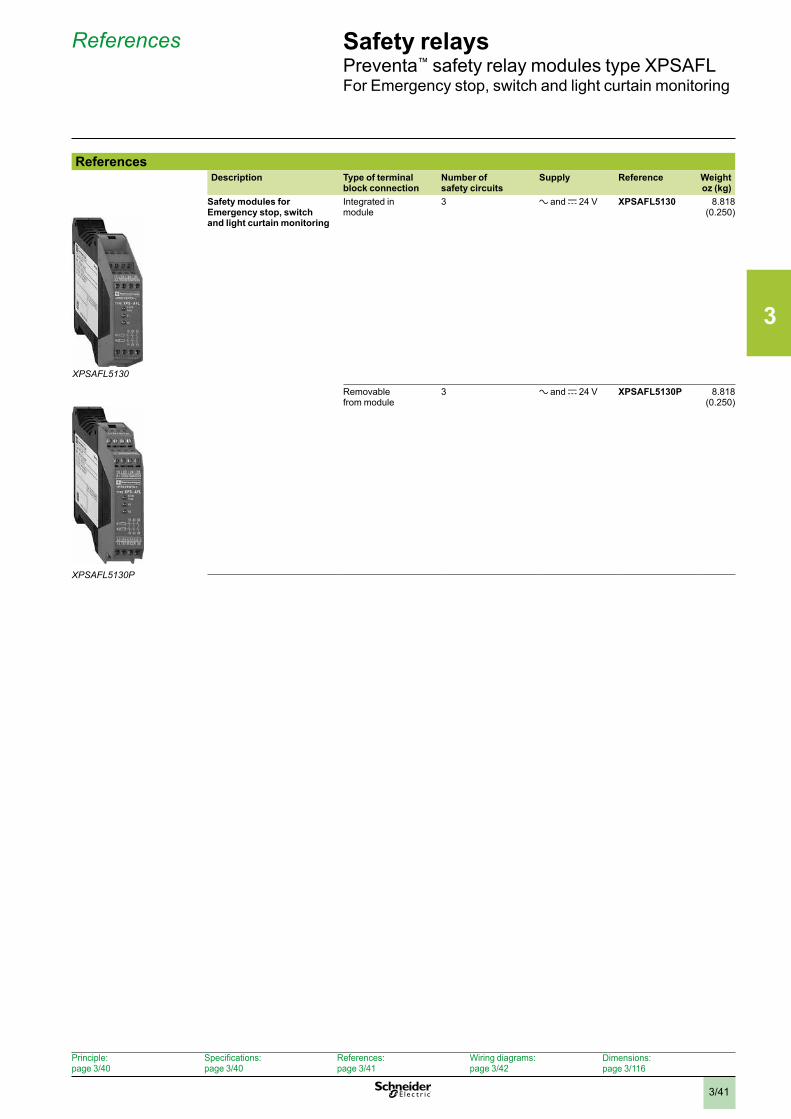
3
3/41
References Safety relaysPreventa™ safety relay modules type XPSAFLFor Emergency stop, switch and light curtain monitoring
ReferencesDescription Type of terminal
block connectionNumber of safety circuits
Supply Reference Weightoz (kg)
Safety modules for Emergency stop, switch and light curtain monitoring
Integrated in module
3 a and c 24 V XPSAFL5130 8.818 (0.250)
Removable from module
3 a and c 24 V XPSAFL5130P 8.818 (0.250)
XPSAFL5130
XPSAFL5130P
Principle: page 3/40
Specifications: page 3/40
References: page 3/41
Wiring diagrams: page 3/42
Dimensions:page 3/116
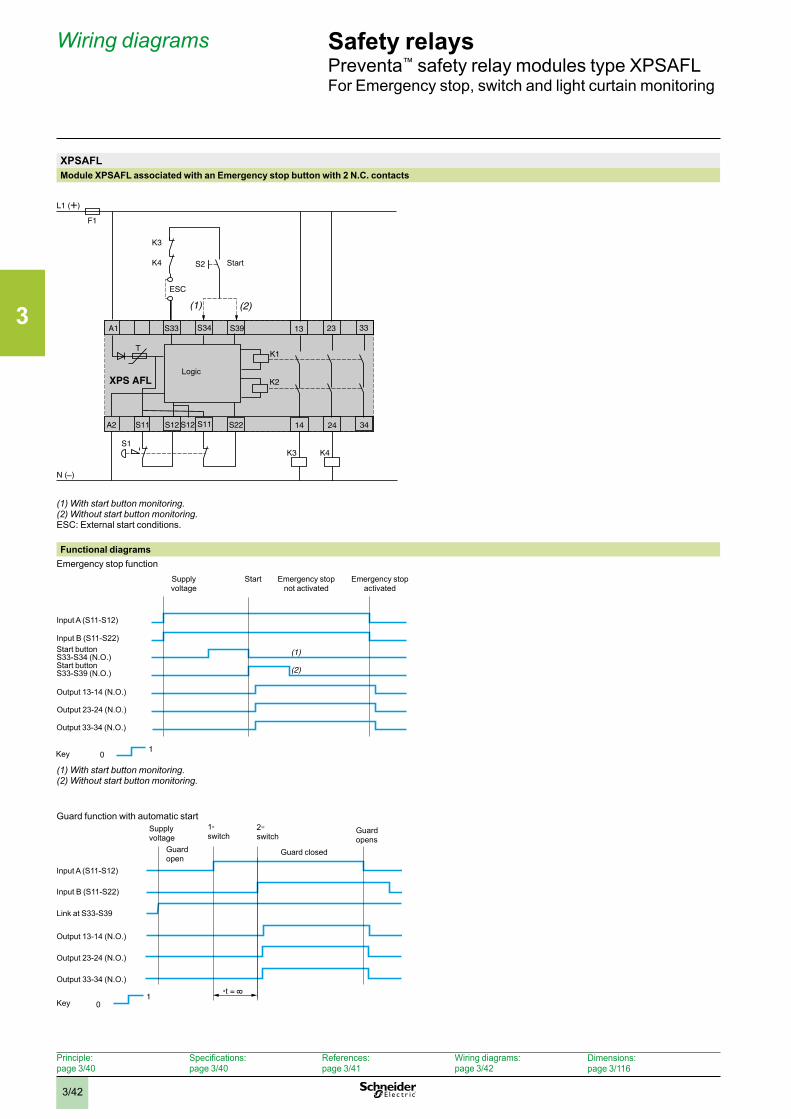
3
3/42
Wiring diagrams Safety relaysPreventa™ safety relay modules type XPSAFLFor Emergency stop, switch and light curtain monitoring
XPSAFLModule XPSAFL associated with an Emergency stop button with 2 N.C. contacts
(1) With start button monitoring .(2) Without start button monitoring .ESC: External start conditions.
Functional diagramsEmergency stop function
(1) With start button monitoring .(2) Without start button monitoring .
Guard function with automatic start
F1
L1 (+)
N ( )
TK1
K2
S1
A1 33
A2
S34S33 S39
XPS AFL
S22S11S12 14 24S11 34
2313
S2
K3
K4
ESC
K4K3
(1) (2)
S12
Start
Logic
1
(1)
(2)
Input A (S11-S12)
Supply voltage
Start Emergency stop not activated
Emergency stop activated
Input B (S11-S22)Start button S33-S34 (N.O.)Start button S33-S39 (N.O.)
Output 13-14 (N.O.)
Output 23-24 (N.O.)
Output 33-34 (N.O.)
Key 0
1t =
Supply voltage
Guard open
1st switch
2nd switch
Guard closed
Guard opens
Input A (S11-S12)
Input B (S11-S22)
Output 13-14 (N.O.)
Output 23-24 (N.O.)
Output 33-34 (N.O.)
Link at S33-S39
Key 0
Principle: page 3/40
Specifications: page 3/40
References: page 3/41
Wiring diagrams: page 3/42
Dimensions:page 3/116
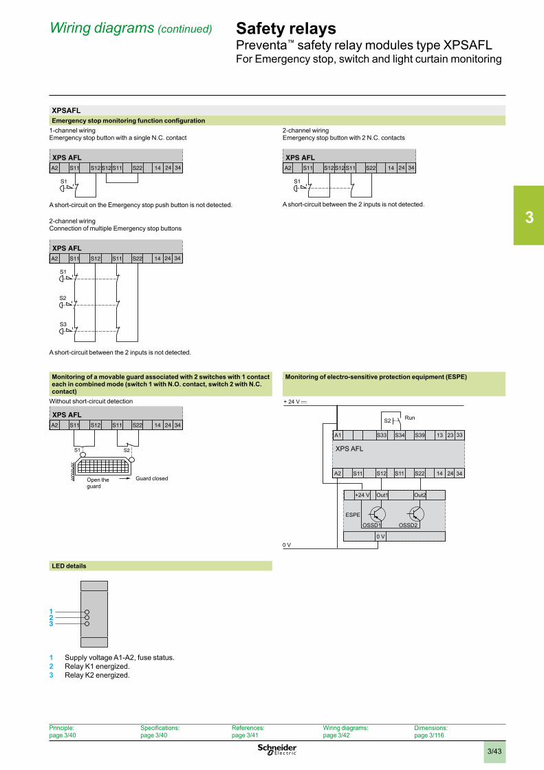
3
3/43
Wiring diagrams (continued) Safety relaysPreventa™ safety relay modules type XPSAFLFor Emergency stop, switch and light curtain monitoring
XPSAFLEmergency stop monitoring function configuration
1-channel wiringEmergency stop button with a single N.C. contact
A short-circuit on the Emergency stop push button is not detected.
2-channel wiringEmergency stop button with 2 N.C. contacts
A short-circuit between the 2 inputs is not detected.
2-channel wiringConnection of multiple Emergency stop buttons
A short-circuit between the 2 inputs is not detected.
Monitoring of a movable guard associated with 2 switches with 1 contact each in combined mode (switch 1 with N.O. contact, switch 2 with N.C. contact)
Monitoring of electro-sensitive protection equipment (ESPE)
Without short-circuit detection
XPS AFL
A1 S33 S34 S39 13 23 33
A2 S11 S12 S11 S22 14 24 34
+ 24 V
+24 V Out1
OSSD1
ESPE
OSSD2
Out2
0 V0 V
S2
LED details
1 Supply voltage A1-A2, fuse status.2 Relay K1 energized.3 Relay K2 energized.
XPS AFL
S1
A2 S11 S12 S11 S22 14 24 34S12
XPS AFL
S1
A2 S11 S12 S11 S22 14 24 34S12
S1
S2
S3
XPS AFLA2 S11 S12 S11 S22 14 24 34
S1 S2
XPS AFLA2 S11 S12 S11 S22 14 24 34
Open the guard
Guard closed
123
Run
Principle: page 3/40
Specifications: page 3/40
References: page 3/41
Wiring diagrams: page 3/42
Dimensions:page 3/116
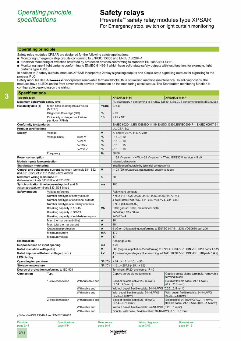
3
3/44
Operating principle, specifications
Safety relaysPreventa™ safety relay modules type XPSARFor Emergency stop, switch or light curtain monitoring
Operating principleSafety relay modules XPSAR are designed for the following safety applications:
b Monitoring Emergency stop circuits conforming to EN/ISO 13850 and EN/IEC 60204-1. b Electrical monitoring of switches activated by protection devices conforming to standard EN 1088/ISO 14119. b Monitoring type 4 light curtains conforming to EN/IEC 61496-1 which have solid-state safety outputs with test function, for example, light curtains type XUSL.
In addition to 7 safety outputs, modules XPSAR incorporate 2 relay signalling outputs and 4 solid-state signalling outputs for signalling to the process PLC.Safety modules XPSARppppppP incorporate removable terminal blocks, thus optimizing machine maintenance. To aid diagnostics, the modules have 4 LEDs on the front cover which provide information on the monitoring circuit status. The Start button monitoring function is configurable depending on the wiring.
SpecificationsModule type XPSAR3p1144 XPSAR3p1144P
Maximum achievable safety level PL e/Category 4 conforming to EN/ISO 13849-1, SILCL 3 conforming to EN/IEC 62061Reliability data (1) Mean Time To dangerous Failure
(MTTFd)Years 277.8
Diagnostic Coverage (DC) % > 99Probability of dangerous Failure per Hour (PFHd)
1/h 2.22 x 10⁻⁹
Conformity to standards EN/IEC 60204-1, EN 1088/ISO 14119, EN/ISO 13850, EN/IEC 60947-1, EN/IEC 60947-5-1Product certifications UL, CSA, BGSupply Voltage V a and c 24, a 115, a 230
Voltage limits c 24 V % - 15…+ 10a 24 V % - 15…+ 10a 115 V % - 15…+ 15a 230 V % - 15…+ 10
Frequency Hz 50/60Power consumption c 24 V version: < 4 W, a24 V version: < 7 VA, 115/230 V version: < 9 VAModule inputs fuse protection Internal, electronicStart button monitoring Yes/No (configurable by terminal connections)Control unit voltage and current (between terminals S11-S52 and S21-S22). 24 V, 115 V and 230 V version
V c 24 (20 mA approx.) (at nominal supply voltage)
Maximum wiring resistance RL (between terminals S11-S52 and S21-S22)
W 50
Synchronization time between inputs A and BAutomatic start, terminals S33, S34 linked
ms 100
Safety outputs Voltage reference Relay hard contactsNumber and type of safety circuits 7 N.O. (13-14/23-24/33-34/43-44/53-54/63-64/73-74)Number and type of additional outputs 4 solid-state (Y31-Y32, Y31-Y64, Y31-Y74, Y31-Y35)Number and type of auxiliary contacts 2 N.C. (81-82/91-92)Breaking capacity in AC-15 VA B300 (inrush: 3600, maintained: 360)Breaking capacity in DC-13 24 V/2 A, L/R = 50 msBreaking capacity of solid-state outputs 24 V/20mA Max. thermal current (Ithe) A 10Max. total thermal current A 40Output fuse protection A 6 gG or 10 fast acting, conforming to EN/IEC 947-5-1, DIN VDE0660 part 200Minimum current mA 170Minimum voltage V 17
Electrical life See page 3/16Response time on input opening ms < 20Rated insulation voltage (Ui) V 300 (degree of pollution 2 conforming to EN/IEC 60947-5-1, DIN VDE 0110 parts 1 & 2)Rated impulse withstand voltage (Uimp.) kV 4 (overvoltage category III, conforming to EN/IEC 60947-5-1, DIN VDE 0110 parts 1 & 2)LED display 4Operating temperature °F (°C) + 14…+ 131 (- 10…+ 55)Storage temperature °F (°C) - 13…+ 267.8 (- 25…+ 85)Degree of protection conforming to IEC 529 Terminals: IP 20, enclosure: IP 40Connection Type Captive screw clamp terminals Captive screw clamp terminals, removable
terminal block1-wire connection Without cable end Solid or flexible cable: 26-14 AWG
(0.14…2.5 mm2)Solid or flexible cable: 24-14 AWG (0.2…2.5 mm2)
With cable end Without bezel, flexible cable: 24-14 AWG (0.25…2.5 mm2)With cable end With bezel, flexible cable: 24-16 AWG
(0.25…1.5 mm2)With bezel, flexible cable: 24-14 AWG (0.25…2.5 mm2)
2-wire connection Without cable end Solid or flexible cable: 26-18 AWG (0.14…0.75 mm2)
Solid cable: 24-18 AWG (0.2…1 mm2), flexible cable: 24-16 AWG (0.2…1.5 mm2)
With cable end Without bezel, flexible cable: 24-18 AWG (0.25…1 mm2)With cable end Double, with bezel, flexible cable: 20-16 AWG (0.5…1.5 mm2)
(1) Per EN/ISO 13849-1 and EN/IEC 62061
Principle: page 3/44
Specifications: page 3/44
References: page 3/45
Wiring diagrams: page 3/46
Dimensions:page 3/116
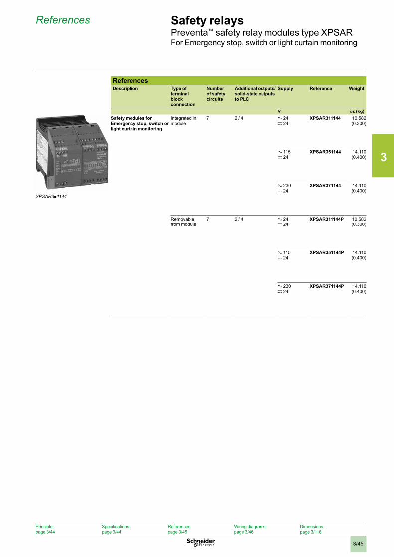
3
3/45
References Safety relaysPreventa™ safety relay modules type XPSARFor Emergency stop, switch or light curtain monitoring
ReferencesDescription Type of
terminal block connection
Number of safety circuits
Additional outputs/solid-state outputs to PLC
Supply Reference Weight
V oz (kg)Safety modules for Emergency stop, switch or light curtain monitoring
Integrated in module
7 2 / 4 a 24 c 24
XPSAR311144 10.582 (0.300)
a 115 c 24
XPSAR351144 14.110 (0.400)
a 230 c 24
XPSAR371144 14.110 (0.400)
Removable from module
7 2 / 4 a 24 c 24
XPSAR311144P 10.582 (0.300)
a 115 c 24
XPSAR351144P 14.110 (0.400)
a 230 c 24
XPSAR371144P 14.110 (0.400)
XPSAR3p1144
Principle: page 3/44
Specifications: page 3/44
References: page 3/45
Wiring diagrams: page 3/46
Dimensions:page 3/116
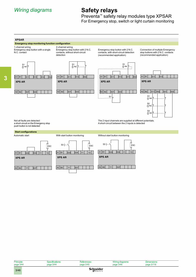
3
3/46
Wiring diagrams Safety relaysPreventa™ safety relay modules type XPSARFor Emergency stop, switch or light curtain monitoring
XPSAREmergency stop monitoring function configuration
1-channel wiringEmergency stop button with a single N.C. contact
2-channel wiringEmergency stop button with 2 N.C. contacts, without short-circuit detection
Emergency stop button with 2 N.C. contacts, with short-circuit detection (recommended application)
Connection of multiple Emergency stop buttons with 2 N.C. contacts (recommended application)
Not all faults are detected: a short-circuit on the Emergency stop push button is not detected
The 2 input channels are supplied at different potentials.A short-circuit between the 2 inputs is detected
Start configurationsAutomatic start With start button monitoring Without start button monitoring
XPS AR
S1
A1 S11 S12 S52
A2 S21 S22
S12B1
B2
XPS AR
S1
A1 S11 S52
A2 S21 S22
S12B1
B2
XPS AR
S1
S1
A1 S11 S11 S52
A2 S21 S22
S12B1
B2
XPS AR
A1 S11
A2 S21 S22S52S11
S12B1
B2
S1
S2
S3
ESC
XPS AR
A1 S33 Y1 Y2
A2 Y1 S37
S34B1
B2
S3 ESC
XPS AR
A1 S33 Y1 Y2
A2 Y1 S37
S34B1
B2
S3 ESC
XPS AR
A1 S33 Y1 Y2
A2 Y1 S37
S34B1
B2
Principle: page 3/44
Specifications: page 3/44
References: page 3/45
Wiring diagrams: page 3/46
Dimensions:page 3/116
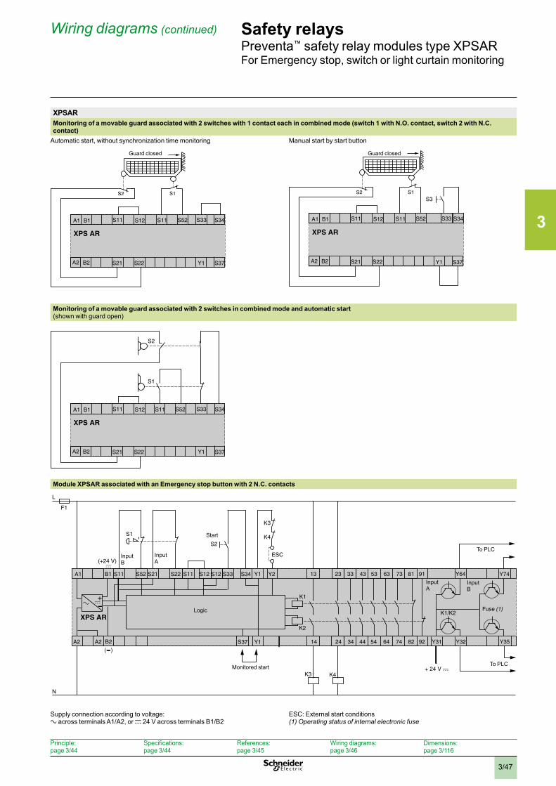
3
3/47
Wiring diagrams (continued) Safety relaysPreventa™ safety relay modules type XPSARFor Emergency stop, switch or light curtain monitoring
XPSARMonitoring of a movable guard associated with 2 switches with 1 contact each in combined mode (switch 1 with N.O. contact, switch 2 with N.C. contact)
Automatic start, without synchronization time monitoring Manual start by start button
Monitoring of a movable guard associated with 2 switches in combined mode and automatic start(shown with guard open)
Module XPSAR associated with an Emergency stop button with 2 N.C. contacts
F1
L
N
K1
K2
S1
A1 23
A2 A2
S52S11 S21
XPS AR
14 24
33
34
13
S2
K3
K4
ESC
K4K3
K1/K2
B1
B2
+
(+24 V)
( )
S12S11 S12 S34S33 Y1
S37 Y1
Y2S22 73
74
63
64
53
54
43
44 9282
9181
Y31 Y32
Y64
Y35
Y74
Logic
Monitored start
To PLC
To PLC
Start
InputA
InputB
InputA
InputB
Fuse (1)
Supply connection according to voltage:a across terminals A1/A2, or c 24 V across terminals B1/B2
ESC: External start conditions(1) Operating status of internal electronic fuse
XPS AR
A1 S11 S12
A2 S21 S22 Y1 S37
B1
B2
S2 S1
S11 S52 S33 S34
Guard closed
XPS AR
A1 S11 S12
A2 S21 S22
B1
B2
S2
S11 S52 S33 S34
Y1 S37
S1S3
Guard closed
XPS AR
A1 S11 S12
A2 S21 S22
B1
B2
S11 S52 S33 S34
S1
S2
Y1 S37
Principle: page 3/44
Specifications: page 3/44
References: page 3/45
Wiring diagrams: page 3/46
Dimensions:page 3/116
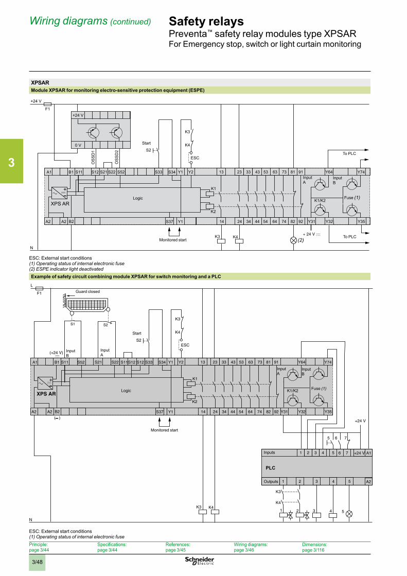
3
3/48
XPSARModule XPSAR for monitoring electro-sensitive protection equipment (ESPE)
+24 V
+24 V
0 V
OS
SD
1
OS
SD
2
(2)
F1
N
K1
K2
A1 23
A2 A2
S12S11 S21
XPS AR
14 24
33
34
13
K4K3
K1/K2
B1
B2
+
S34S33 Y1
S37 Y1
Y2S22 S52 73
74
63
64
53
54
43
44 9282
9181
Y31 Y32
Y64
Y35
Y74
S2K4
K3
ESC
Logic
Monitored start
To PLC
To PLC
Start
InputA
InputB
Fuse (1)
ESC: External start conditions(1) Operating status of internal electronic fuse(2) ESPE indicator light deactivatedExample of safety circuit combining module XPSAR for switch monitoring and a PLC
S1 S2
2 31
1 43 5 +24 V
321
2
6 75
A1
A2
76
4 5
4
K4
K3
5
F1
L
N
K1
K2
A1 23
A2 A2
S52S11 S21
XPS AR
14 24
33
34
13
S2
K3
K4
ESC
K4K3
K1/K2
B1
B2
+
(+24 V)
( )
S12S11 S12 S34S33 Y1
S37 Y1
Y2S22 73
74
63
64
53
54
43
44 9282
9181
Y31 Y32
Y64
+24 V
Y35
Y74
Logic
Monitored start
Start
InputA
InputB
InputA
InputB
Fuse (1)
PLC
Guard closed
Inputs
Outputs
ESC: External start conditions(1) Operating status of internal electronic fuse
Wiring diagrams (continued) Safety relaysPreventa™ safety relay modules type XPSARFor Emergency stop, switch or light curtain monitoring
Principle: page 3/44
Specifications: page 3/44
References: page 3/45
Wiring diagrams: page 3/46
Dimensions:page 3/116
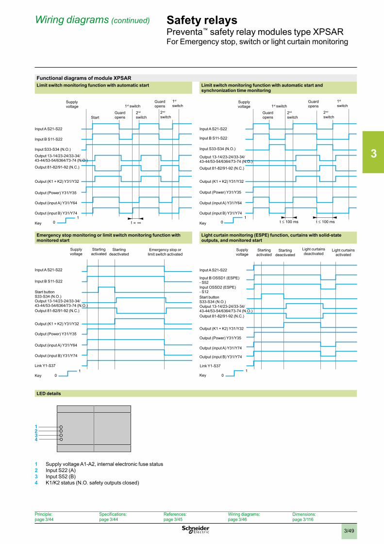
3
3/49
Functional diagrams of module XPSARLimit switch monitoring function with automatic start Limit switch monitoring function with automatic start and
synchronization time monitoring
Emergency stop monitoring or limit switch monitoring function with monitored start
Light curtain monitoring (ESPE) function, curtains with solid-state outputs, and monitored start
1 0 t 100 mst 100 ms
10
Starting deactivated
Supplyvoltage
Key
Input A S21-S22
Input B S11-S22
Start buttonS33-S34 (N.O.)Output 13-14/23-24/33-34/ 43-44/53-54/6364/73-74 (N.O.)Output 81-82/91-92 (N.C.)
Link Y1-S37
Starting activated
Output (input A) Y31/Y64
Output (Power) Y31/Y35
Output (K1 + K2) Y31/Y32
Output (input B) Y31/Y74
Emergency stop or limit switch activated
1 0
Supplyvoltage
Key
Input A S21-S22
Input B OSSD1 (ESPE) - S52Input OSSD2 (ESPE) - S12
Output 13-14/23-24/33-34/ 43-44/53-54/6364/73-74 (N.O.)Output 81-82/91-92 (N.C.)
Output (input B) Y31/Y74
Output (input A) Y31/Y74
Output (Power) Y31/Y35
Output (K1 + K2) Y31/Y32
Link Y1-S37
Start buttonS33-S34 (N.O.)
Starting deactivated
Starting activated
Light curtains activated
Light curtains deactivated
LED details
1 0 t 100 mst 100 ms
1234
1 Supply voltage A1-A2, internal electronic fuse status2 Input S22 (A)3 Input S52 (B)4 K1/K2 status (N.O. safety outputs closed)
t =1
0
Guard opens
Supplyvoltage
Key
Input A S21-S22
Input B S11-S22
Input S33-S34 (N.O.)
Output 13-14/23-24/33-34/ 43-44/53-54/6364/73-74 (N.O.)
Output 81-82/91-92 (N.C.)
Output (input B) Y31/Y74
Start
1st switch
2nd
switch
Guard opens
2nd switch
1st switch
Output (input A) Y31/Y64
Output (Power) Y31/Y35
Output (K1 + K2) Y31/Y32
1 0 t 100 mst 100 ms
1 0 t 100 mst 100 ms
Guard opens
Supply voltage
Key
Input A S21-S22
Input B S11-S22
Input S33-S34 (N.O.)
Output 13-14/23-24/33-34/ 43-44/53-54/6364/73-74 (N.O.)
Output 81-82/91-92 (N.C.)
Output (input B) Y31/Y74
1st switch
2nd switch
Guardopens
2nd switch
1st switch
Output (input A) Y31/Y64
Output (Power) Y31/Y35
Output (K1 + K2) Y31/Y32
Wiring diagrams (continued) Safety relaysPreventa™ safety relay modules type XPSARFor Emergency stop, switch or light curtain monitoring
Principle: page 3/44
Specifications: page 3/44
References: page 3/45
Wiring diagrams: page 3/46
Dimensions:page 3/116
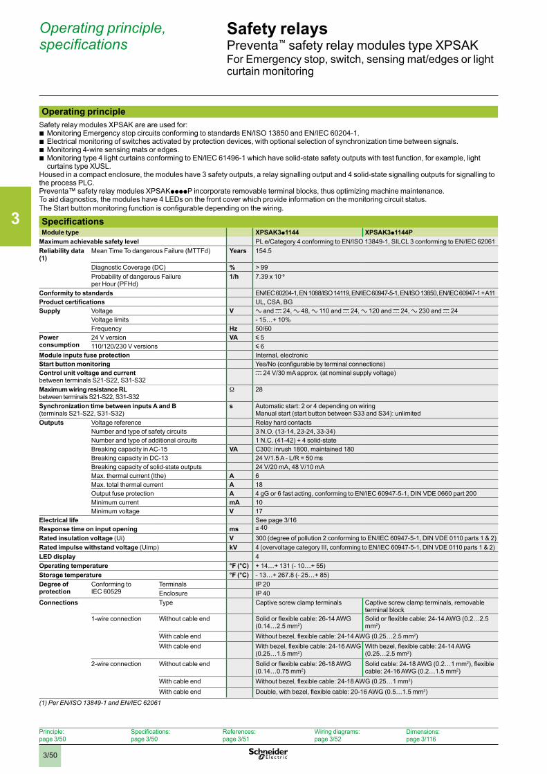
3
3/50
Safety relaysPreventa™ safety relay modules type XPSAKFor Emergency stop, switch, sensing mat/edges or light curtain monitoring
Operating principleSafety relay modules XPSAK are are used for:
b Monitoring Emergency stop circuits conforming to standards EN/ISO 13850 and EN/IEC 60204-1. b Electrical monitoring of switches activated by protection devices, with optional selection of synchronization time between signals. b Monitoring 4-wire sensing mats or edges. b Monitoring type 4 light curtains conforming to EN/IEC 61496-1 which have solid-state safety outputs with test function, for example, light curtains type XUSL.
Housed in a compact enclosure, the modules have 3 safety outputs, a relay signalling output and 4 solid-state signalling outputs for signalling to the process PLC.Preventa™ safety relay modules XPSAKppppP incorporate removable terminal blocks, thus optimizing machine maintenance. To aid diagnostics, the modules have 4 LEDs on the front cover which provide information on the monitoring circuit status.The Start button monitoring function is configurable depending on the wiring.
SpecificationsModule type XPSAK3p1144 XPSAK3p1144P
Maximum achievable safety level PL e/Category 4 conforming to EN/ISO 13849-1, SILCL 3 conforming to EN/IEC 62061Reliability data (1)
Mean Time To dangerous Failure (MTTFd) Years 154.5
Diagnostic Coverage (DC) % > 99Probability of dangerous Failure per Hour (PFHd)
1/h 7.39 x 10⁻⁹
Conformity to standards EN/IEC 60204-1, EN 1088/ISO 14119, EN/IEC 60947-5-1, EN/ISO 13850, EN/IEC 60947-1 + A11Product certifications UL, CSA, BGSupply Voltage V a and c 24, a 48, a 110 and c 24, a 120 and c 24, a 230 and c 24
Voltage limits - 15…+ 10%Frequency Hz 50/60
Power consumption
24 V version VA y 5110/120/230 V versions y 6
Module inputs fuse protection Internal, electronicStart button monitoring Yes/No (configurable by terminal connections)Control unit voltage and current between terminals S21-S22, S31-S32
c 24 V/30 mA approx. (at nominal supply voltage)
Maximum wiring resistance RL between terminals S21-S22, S31-S32
W 28
Synchronization time between inputs A and B(terminals S21-S22, S31-S32)
s Automatic start: 2 or 4 depending on wiring Manual start (start button between S33 and S34): unlimited
Outputs Voltage reference Relay hard contactsNumber and type of safety circuits 3 N.O. (13-14, 23-24, 33-34)Number and type of additional circuits 1 N.C. (41-42) + 4 solid-stateBreaking capacity in AC-15 VA C300: inrush 1800, maintained 180Breaking capacity in DC-13 24 V/1.5 A - L/R = 50 msBreaking capacity of solid-state outputs 24 V/20 mA, 48 V/10 mAMax. thermal current (Ithe) A 6Max. total thermal current A 18Output fuse protection A 4 gG or 6 fast acting, conforming to EN/IEC 60947-5-1, DIN VDE 0660 part 200Minimum current mA 10Minimum voltage V 17
Electrical life See page 3/16Response time on input opening ms ≤ 40Rated insulation voltage (Ui) V 300 (degree of pollution 2 conforming to EN/IEC 60947-5-1, DIN VDE 0110 parts 1 & 2)Rated impulse withstand voltage (Uimp) kV 4 (overvoltage category III, conforming to EN/IEC 60947-5-1, DIN VDE 0110 parts 1 & 2)LED display 4Operating temperature °F (°C) + 14…+ 131 (- 10…+ 55)Storage temperature °F (°C) - 13…+ 267.8 (- 25…+ 85)Degree of protection
Conforming to IEC 60529
Terminals IP 20Enclosure IP 40
Connections Type Captive screw clamp terminals Captive screw clamp terminals, removable terminal block
1-wire connection Without cable end Solid or flexible cable: 26-14 AWG (0.14…2.5 mm2)
Solid or flexible cable: 24-14 AWG (0.2…2.5 mm2)
With cable end Without bezel, flexible cable: 24-14 AWG (0.25…2.5 mm2)With cable end With bezel, flexible cable: 24-16 AWG
(0.25…1.5 mm2)With bezel, flexible cable: 24-14 AWG (0.25…2.5 mm2)
2-wire connection Without cable end Solid or flexible cable: 26-18 AWG (0.14…0.75 mm2)
Solid cable: 24-18 AWG (0.2…1 mm2), flexible cable: 24-16 AWG (0.2…1.5 mm2)
With cable end Without bezel, flexible cable: 24-18 AWG (0.25…1 mm2)With cable end Double, with bezel, flexible cable: 20-16 AWG (0.5…1.5 mm2)
(1) Per EN/ISO 13849-1 and EN/IEC 62061
Operating principle, specifications
Principle: page 3/50
Specifications: page 3/50
References: page 3/51
Wiring diagrams: page 3/52
Dimensions:page 3/116
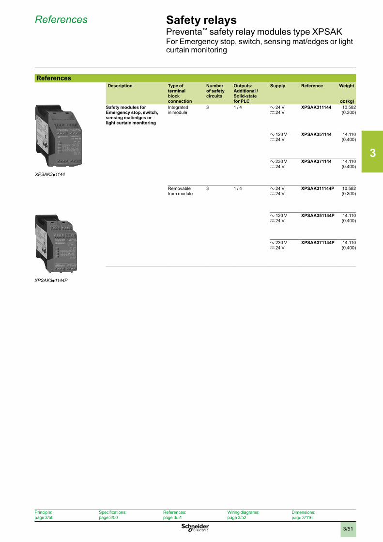
3
3/51
Safety relaysPreventa™ safety relay modules type XPSAKFor Emergency stop, switch, sensing mat/edges or light curtain monitoring
References
ReferencesDescription Type of
terminal block connection
Number of safety circuits
Outputs: Additional / Solid-state for PLC
Supply Reference Weight
oz (kg)Safety modules for Emergency stop, switch, sensing mat/edges or light curtain monitoring
Integrated in module
3 1 / 4 a 24 Vc 24 V
XPSAK311144 10.582 (0.300)
a 120 Vc 24 V
XPSAK351144 14.110 (0.400)
a 230 Vc 24 V
XPSAK371144 14.110 (0.400)
Removable from module
3 1 / 4 a 24 Vc 24 V
XPSAK311144P 10.582 (0.300)
a 120 Vc 24 V
XPSAK351144P 14.110 (0.400)
a 230 Vc 24 V
XPSAK371144P 14.110 (0.400)
XPSAK3p1144P
XPSAK3p1144
Principle: page 3/50
Specifications: page 3/50
References: page 3/51
Wiring diagrams: page 3/52
Dimensions:page 3/116
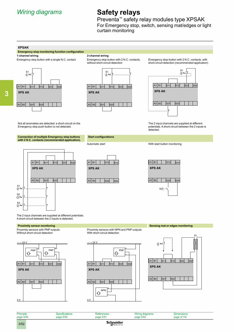
3
3/52
Safety relaysPreventa™ safety relay modules type XPSAKFor Emergency stop, switch, sensing mat/edges or light curtain monitoring
Wiring diagrams
XPSAKEmergency stop monitoring function configuration
1-channel wiring 2-channel wiringEmergency stop button with a single N.C. contact Emergency stop button with 2 N.C. contacts,
without short-circuit detectionEmergency stop button with 2 N.C. contacts, with short-circuit detection (recommended application)
Not all anomalies are detected: a short-circuit on the Emergency stop push button is not detected.
The 2 input channels are supplied at different potentials. A short-circuit between the 2 inputs is detected.
Connection of multiple Emergency stop buttons with 2 N.C. contacts (recommended application).
Start configurations
Automatic start With start button monitoring
The 2 input channels are supplied at different potentials. A short-circuit between the 2 inputs is detected.
Proximity sensor monitoring Sensing mat or edges monitoringProximity sensors with PNP outputsWithout short-circuit detection
Proximity sensors with NPN and PNP outputsWith short-circuit detection
XPS AK
S1
A1 S11 S31 S32
A2 S21 S22
S12B1
B2
XPS AK
S1
A1 S11 S31 S32
A2 S21 S22
S12B1
B2
XPS AK
S1
A1 S11 S31 S32
A2 S21 S22
S12B1
B2
XPS AK
A1 S11 S31 S32
A2 S21 S22
S12B1
B2
S1
S2
S3
XPS AK
A1 S13 S14
A2 S33 S34
B1
B2
XPS AK
A1 S13 S14
A2 S33 S34
B1
B2
S2
XPS AK
S1
A1 S11 S31 S32
A2 S21 S22
S12B1
B2
XPS AK
A1 S11 S31 S32
A2 S21 S22
S12B1
B2
0 V
PNP PNP+ +
- -
XPS AK
A1 S11 S31 S32
A2 S21 S22
S12B1
B2
0 V
NPN
PNP
+
+
–
–
Principle: page 3/50
Specifications: page 3/50
References: page 3/51
Wiring diagrams: page 3/52
Dimensions:page 3/116
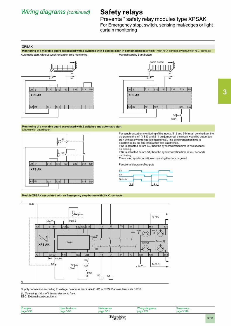
3
3/53
Safety relaysPreventa™ safety relay modules type XPSAKFor Emergency stop, switch, sensing mat/edges or light curtain monitoring
Wiring diagrams (continued)
XPSAKMonitoring of a movable guard associated with 2 switches with 1 contact each in combined mode (switch 1 with N.O. contact, switch 2 with N.C. contact)
Automatic start, without synchronization time monitoring Manual start by Start button
Monitoring of a movable guard associated with 2 switches and automatic start(shown with guard open)
For synchronization monitoring of the inputs, S13 and S14 must be wired per the diagram to the left (if S13 and S14 are jumpered, the result would be automatic start without synchronization monitoring). The synchronization time is determined by the first limit switch that is activated.If S1 is actuated before S2, then the synchronization time is two secondson closing.If S2 is actuated before S1, then the synchronization time is four secondson closing.There is no synchronization on opening the door or guard.
Functional diagram of outputs
Module XPSAK associated with an Emergency stop button with 2 N.C. contacts
Supply connection according to voltage: a across terminals A1/A2, or c 24 V across terminals B1/B2.(1) Operating status of internal electronic fuse .ESC: External start conditions.
XPS AK
A1 S11 S12
A2 S21 S22
B1
B2
S2 S1
S31 S32 S13 S14
XPS AK
A1 S11 S12
A2 S21 S22
B1
B2
S2 S1
S31 S32 S13 S14
S2
S33 S34
Guard closed
Start
XPS AK
A1 S11 S12
A2 S21 S22
B1
B2
S31 S32 S13 S14
S1
S2
S33 S342 s 4 s
S1
S2Outputs
F1L
N
K1
K2
S1
A1 23
A2
S12S11 S31
XPS AK
S22S21 14 24
13S13
S2
K3
K4
ESCK4K3
K1/K2
B1
B2
+
(+24 V)
( )
S32
S33
S14
S34
S1
33
34
41
42 Y31 Y32
Y64
Y54
Y74
To PLC
Fuse (1)
Start
Input A
Logic
To PLC
Input B
InputA
InputB
Principle: page 3/50
Specifications: page 3/50
References: page 3/51
Wiring diagrams: page 3/52
Dimensions:page 3/116
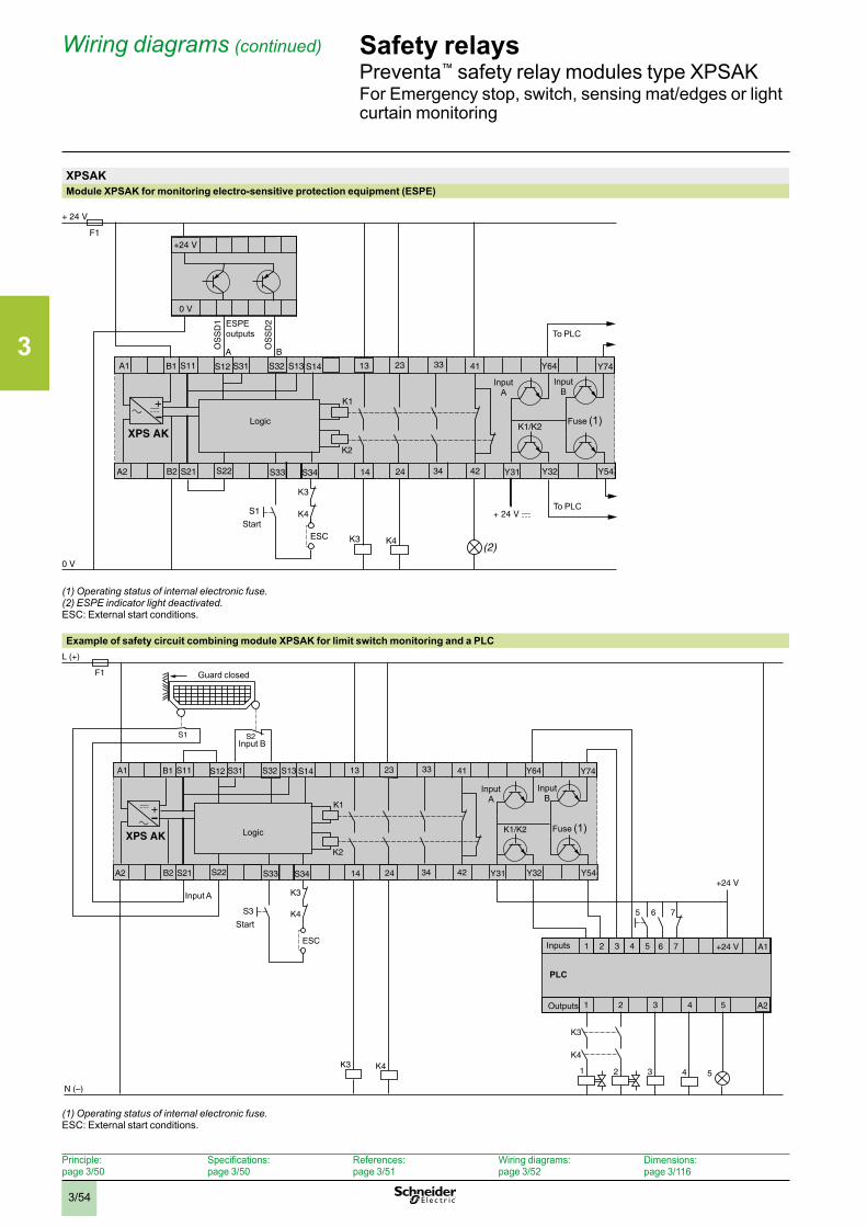
3
3/54
Safety relaysPreventa™ safety relay modules type XPSAKFor Emergency stop, switch, sensing mat/edges or light curtain monitoring
Wiring diagrams (continued)
XPSAKModule XPSAK for monitoring electro-sensitive protection equipment (ESPE)
(1) Operating status of internal electronic fuse .(2) ESPE indicator light deactivated .ESC: External start conditions.
Example of safety circuit combining module XPSAK for limit switch monitoring and a PLC
(1) Operating status of internal electronic fuse .ESC: External start conditions.
F1
+ 24 V
0 V
K1
K2
A1 23
A2
S12S11 S31
XPS AK
S22S21 14 24
13S13
S1
K3
K4
ESC K4K3
K1/K2
B1
B2
+
S32
S33
S14
S34
33
34
41
42 Y31 Y32
Y64
Y54
Y74
+24 V
0 V
A B
OS
SD
1
OS
SD
2
(2)
To PLC
To PLC
Fuse (1)
Start
Logic
ESPE outputs
InputA
InputB
F1
L (+)
N (–)
K1
K2
A1 23
A2
S12S11 S31
XPS AK
S22S21 14 24
13S13
S3
K3
K4
ESC
K4K3
K1/K2
B1
B2
+
S32
S33
S14
S34
33
34
41
42 Y31 Y32
Y64
Y54
Y74
2 31
1 43 5 +24 V
+24 V
321
2
6 75
A1
A2
76
4 5
S1 S2
4
K4
K3
5
Fuse (1)
Start
Input A
Input B
Logic
Guard closed
Inputs
Outputs
PLC
InputA
InputB
Principle: page 3/50
Specifications: page 3/50
References: page 3/51
Wiring diagrams: page 3/52
Dimensions:page 3/116
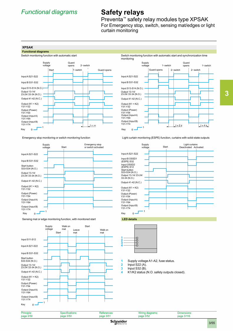
3
3/55
Safety relaysPreventa™ safety relay modules type XPSAKFor Emergency stop, switch, sensing mat/edges or light curtain monitoring
Functional diagrams
XPSAKFunctional diagrams
Switch monitoring function with automatic start Switch monitoring function with automatic start and synchronization time monitoring
Emergency stop monitoring or switch monitoring function Light curtain monitoring (ESPE) function, curtains with solid-state outputs
Sensing mat or edge monitoring function, with monitored start LED details
1 Supply voltage A1-A2, fuse status.2 Input S22 (A).3 Input S32 (B).4 K1/K2 status (N.O. safety outputs closed).
t =0
1Key
Output (K1 + K2)Y31-Y32
Output 41-42 (N.C.)
Input B S31-S32
Input A S21-S22
Input S13-S14 (N.O.)Output 13-14/ 23-24/ 33-34 (N.O.)
Output (Power) Y31-Y54Output (Input A) Y31-Y64Output (Input B) Y31-Y74
Start
Supply voltage
Guard opens
Guard opens
2nd switch
1st switch
t = 2 s t = 4 s
Output (K1 + K2)Y31-Y32
Output 41-42 (N.C.)
Input B S31-S32
Input A S21-S22
Input S13-S14 (N.O.)Output 13-14/ 23-24/ 33-34 (N.O.)
Output (Power) Y31-Y54Output (Input A)Y31-Y64Output (Input B) Y31-Y74
Supply voltage
Guard opens
1st switch
2nd switch
Guardopens
2nd switch
1st switch
01
Key
01
Key
Output (K1 + K2)Y31-Y32
Output 41-42 (N.C.)
Input B S31-S32
Input A S21-S22
Start buttonS33-S34 (N.O.)
Output 13-14/ 23-24/ 33-34 (N.O.)
Output (Power)Y31-Y54Output (Input A) Y31-Y64
Output (Input B) Y31-Y74
Supply voltage Start
Emergency stop or switch activated
Output (K1 + K2)Y31-Y32
Output 41-42 (N.C.)
Input B OSSD1 (ESPE) S32
Input A S21-S22
Output 13-14/ 23-24/ 33-34 (N.O.)
Output (Power) Y31-Y54Output (Input A) Y31-Y64Output (Input B) Y31-Y74
Input OSSD2 (ESPE) S12Start button S33-S34 (N.O.)
Supply voltage Start
Light curtains Deactivated Activated
01
Key
Output (K1 + K2)Y31-Y32
Output 41-42 (N.C.)
Input B S31-S32
Input A S21-S22
Start button S33-S34 (N.O.)
Output 13-14/ 23-24/ 33-34 (N.O.)
Output (Power)Y31-Y54Output (Input A)Y31-Y64
Output (Input B)Y31-Y74
Supply voltage
Start
Input S11-S12
Walk on mat Leave
mat
StartWalk on mat
01
Key
1234
Principle: page 3/50
Specifications: page 3/50
References: page 3/51
Wiring diagrams: page 3/52
Dimensions:page 3/116
3
3/56
Safety relaysPreventa™ safety relay modules types XPSBAE, XPSBCE, XPSBFFor electrical monitoring of two-hand control stations
Operating principle
Principle: page 3/56
Specifications: page 3/57
References: page 3/59
Wiring diagrams: page 3/60
Dimensions:page 3/116
Operating principleTwo-hand control stations are designed to provide protection against hand injury. They require machine operators to keep their hands clear of the hazardous movement zone.
The use of two-hand control is an individual protective measure, which can protect only one operator. Separate two-hand control stations must be provided for each operator in a multiple-worker environment. Safety relay modules XPSBAE, XPSBCE and XPSBF for two-hand control stations comply with the requirements of European standard EN 574/ISO 13851 for two-hand control systems.
The control stations must be designed and installed such that they cannot be activated involuntarily or easily rendered inoperative. Depending on the application, the requirements of type C standards specific to the machinery involved must be met (additional personal protection methods may have to be considered).
To initiate a hazardous movement, both operators (two-hand control pushbuttons) must be activated within an interval y 0.5 s (synchronous activation). If one of the two pushbuttons is released during a hazardous operation, the control sequence is cancelled. Resumption of the hazardous operation is possible only if both pushbuttons are returned to their initial position and reactivated within the required time interval.
The control sequence does not occur if:• Both two-hand control push buttons are pressed during a time period greater than
0.5 seconds,• A short-circuit is present in a push button contact,• The feedback loop is not closed at start-up. The safety distance between the control units and the hazardous zone must be sufficient that when only one operator is released, the hazardous zone cannot be reached before the hazardous movement has been completed or stopped.
XPSBAEThis module is designed for use on lighter duty applications where a two-hand control function is desired, but where the Performance Level required (PLr) is PLa, b, or c and the two-hand control requirements meet Type III A (per EN 574/ISO 13851). This module is not to be used for applications, such as presses, which require a Type III C module or where the application is not PLa, b, or c. For press applications, for applications in PLd or e, or if application calls for a Type III C module, use XPSBCE or XPSBF module.
XPSBCE and XPSBFThese modules can be used on applications, such as presses, which require a Type III C module. The XPSBCE and XPSBF can be used for a two-hand control application, including presses and similar equipment.
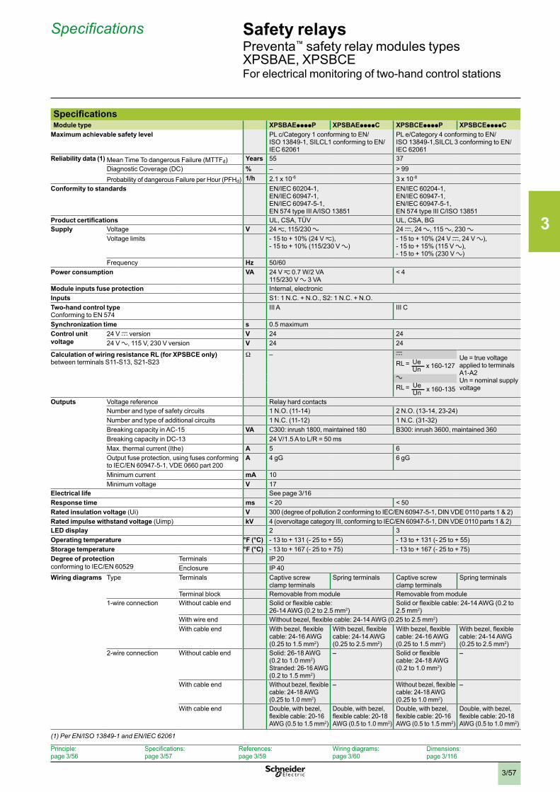
3
3/57
Safety relaysPreventa™ safety relay modules types XPSBAE, XPSBCEFor electrical monitoring of two-hand control stations
Specifications
Principle: page 3/56
Specifications: page 3/57
References: page 3/59
Wiring diagrams: page 3/60
Dimensions:page 3/116
SpecificationsModule type XPSBAEppppP XPSBAEppppC XPSBCEppppP XPSBCEppppC
Maximum achievable safety level PL c/Category 1 conforming to EN/ISO 13849-1, SILCL1 conforming to EN/IEC 62061
PL e/Category 4 conforming to EN/ISO 13849-1,SILCL 3 conforming to EN/IEC 62061
Reliability data (1) Mean Time To dangerous Failure (MTTFd) Years 55 37Diagnostic Coverage (DC) % – > 99Probability of dangerous Failure per Hour (PFHd) 1/h 2.1 x 10⁻⁶ 3 x 10⁻⁸
Conformity to standards EN/IEC 60204-1, EN/IEC 60947-1, EN/IEC 60947-5-1, EN 574 type III A/ISO 13851
EN/IEC 60204-1, EN/IEC 60947-1, EN/IEC 60947-5-1, EN 574 type III C/ISO 13851
Product certifications UL, CSA, TÜV UL, CSA, BGSupply Voltage V 24 z, 115/230 a 24 c, 24 a, 115 a, 230 a
Voltage limits - 15 to + 10% (24 V z), - 15 to + 10% (115/230 V a)
- 15 to + 10% (24 V c, 24 V a),- 15 to + 15% (115 V a),- 15 to + 10% (230 V a)
Frequency Hz 50/60Power consumption VA 24 V z 0.7 W/2 VA
115/230 V a 3 VA< 4
Module inputs fuse protection Internal, electronicInputs S1: 1 N.C. + N.O., S2: 1 N.C. + N.O.Two-hand control typeConforming to EN 574
III A III C
Synchronization time s 0.5 maximumControl unit voltage
24 V c version V 24 2424 V a, 115 V, 230 V version V 24 24
Calculation of wiring resistance RL (for XPSBCE only)between terminals S11-S13, S21-S23
W – cUe = true voltage applied to terminals A1-A2Un = nominal supply voltage
RL =
a
RL =
Outputs Voltage reference Relay hard contactsNumber and type of safety circuits 1 N.O. (11-14) 2 N.O. (13-14, 23-24)Number and type of additional circuits 1 N.C. (11-12) 1 N.C. (31-32)Breaking capacity in AC-15 VA C300: inrush 1800, maintained 180 B300: inrush 3600, maintained 360Breaking capacity in DC-13 24 V/1.5 A to L/R = 50 msMax. thermal current (Ithe) A 5 6Output fuse protection, using fuses conforming to IEC/EN 60947-5-1, VDE 0660 part 200
A 4 gG 6 gG
Minimum current mA 10Minimum voltage V 17
Electrical life See page 3/16Response time ms < 20 < 50Rated insulation voltage (Ui) V 300 (degree of pollution 2 conforming to IEC/EN 60947-5-1, DIN VDE 0110 parts 1 & 2)Rated impulse withstand voltage (Uimp) kV 4 (overvoltage category III, conforming to IEC/EN 60947-5-1, DIN VDE 0110 parts 1 & 2)LED display 2 3Operating temperature °F (°C) - 13 to + 131 (- 25 to + 55) - 13 to + 131 (- 25 to + 55)Storage temperature °F (°C) - 13 to + 167 (- 25 to + 75) - 13 to + 167 (- 25 to + 75)Degree of protection conforming to IEC/EN 60529
Terminals IP 20Enclosure IP 40
Wiring diagrams Type Terminals Captive screw clamp terminals
Spring terminals Captive screw clamp terminals
Spring terminals
Terminal block Removable from module Removable from module1-wire connection Without cable end Solid or flexible cable:
26-14 AWG (0.2 to 2.5 mm2)Solid or flexible cable: 24-14 AWG (0.2 to 2.5 mm2)
With wire end Without bezel, flexible cable: 24-14 AWG (0.25 to 2.5 mm2)With cable end With bezel, flexible
cable: 24-16 AWG (0.25 to 1.5 mm2)
With bezel, flexible cable: 24-14 AWG (0.25 to 2.5 mm2)
With bezel, flexible cable: 24-16 AWG (0.25 to 1.5 mm2)
With bezel, flexible cable: 24-14 AWG (0.25 to 2.5 mm2)
2-wire connection Without cable end Solid: 26-18 AWG (0.2 to 1.0 mm2) Stranded: 26-16 AWG (0.2 to 1.5 mm2)
– Solid or flexible cable: 24-18 AWG (0.2 to 1.0 mm2)
–
With cable end Without bezel, flexible cable: 24-18 AWG (0.25 to 1.0 mm2)
– Without bezel, flexible cable: 24-18 AWG (0.25 to 1.0 mm2)
–
With cable end Double, with bezel, flexible cable: 20-16 AWG (0.5 to 1.5 mm2)
Double, with bezel, flexible cable: 20-18 AWG (0.5 to 1.0 mm2)
Double, with bezel, flexible cable: 20-16 AWG (0.5 to 1.5 mm2)
Double, with bezel, flexible cable: 20-18 AWG (0.5 to 1.0 mm2)
(1) Per EN/ISO 13849-1 and EN/IEC 62061
UeUn x 160-127
UeUn x 160-135
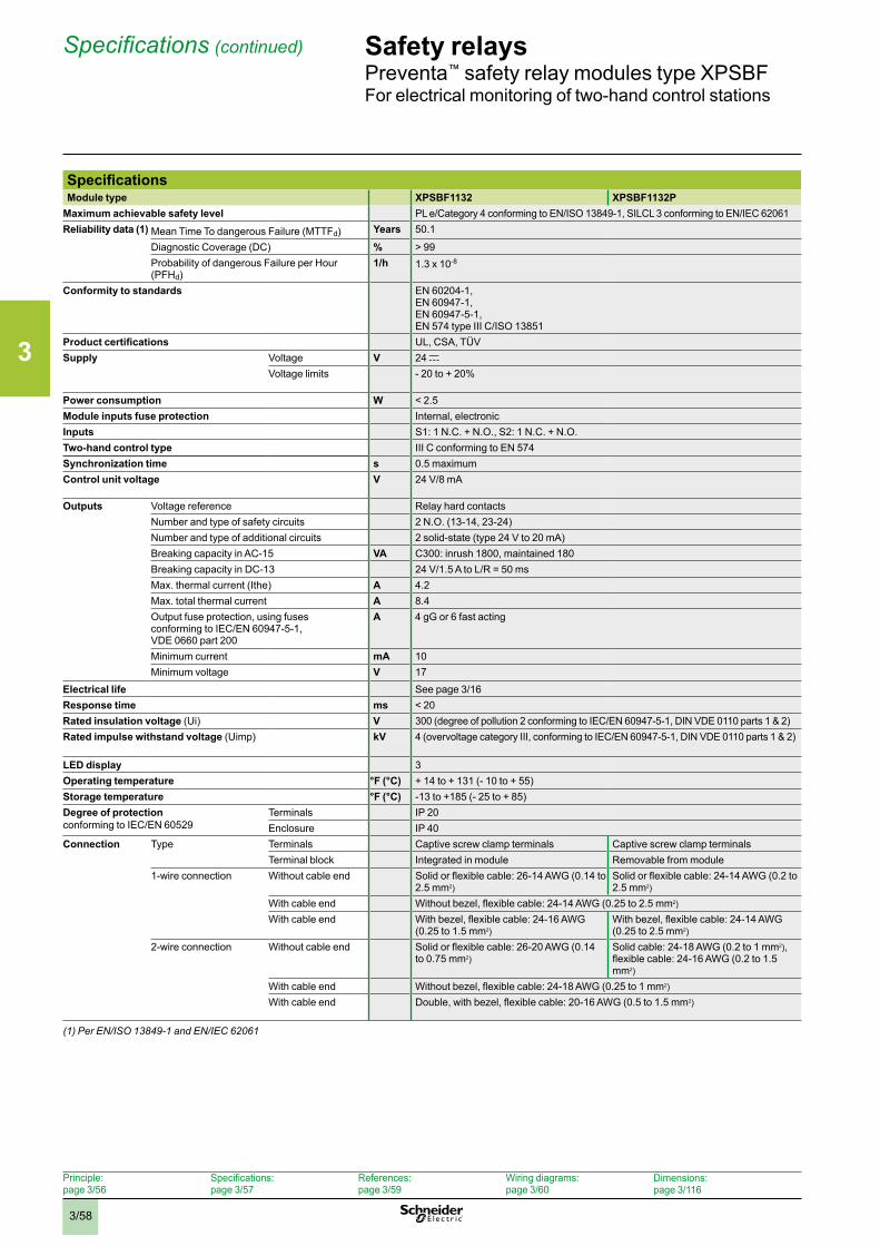
3
3/58
Safety relaysPreventa™ safety relay modules type XPSBFFor electrical monitoring of two-hand control stations
Specifications (continued)
Principle: page 3/56
Specifications: page 3/57
References: page 3/59
Wiring diagrams: page 3/60
Dimensions:page 3/116
SpecificationsModule type XPSBF1132 XPSBF1132P
Maximum achievable safety level PL e/Category 4 conforming to EN/ISO 13849-1, SILCL 3 conforming to EN/IEC 62061 Reliability data (1) Mean Time To dangerous Failure (MTTFd) Years 50.1
Diagnostic Coverage (DC) % > 99Probability of dangerous Failure per Hour (PFHd)
1/h 1.3 x 10⁻⁸
Conformity to standards EN 60204-1, EN 60947-1, EN 60947-5-1, EN 574 type III C/ISO 13851
Product certifications UL, CSA, TÜVSupply Voltage V 24 c
Voltage limits - 20 to + 20%
Power consumption W < 2.5Module inputs fuse protection Internal, electronicInputs S1: 1 N.C. + N.O., S2: 1 N.C. + N.O.Two-hand control type III C conforming to EN 574Synchronization time s 0.5 maximumControl unit voltage V 24 V/8 mA
Outputs Voltage reference Relay hard contactsNumber and type of safety circuits 2 N.O. (13-14, 23-24)Number and type of additional circuits 2 solid-state (type 24 V to 20 mA)Breaking capacity in AC-15 VA C300: inrush 1800, maintained 180Breaking capacity in DC-13 24 V/1.5 A to L/R = 50 msMax. thermal current (Ithe) A 4.2Max. total thermal current A 8.4Output fuse protection, using fuses conforming to IEC/EN 60947-5-1, VDE 0660 part 200
A 4 gG or 6 fast acting
Minimum current mA 10Minimum voltage V 17
Electrical life See page 3/16Response time ms < 20Rated insulation voltage (Ui) V 300 (degree of pollution 2 conforming to IEC/EN 60947-5-1, DIN VDE 0110 parts 1 & 2)Rated impulse withstand voltage (Uimp) kV 4 (overvoltage category III, conforming to IEC/EN 60947-5-1, DIN VDE 0110 parts 1 & 2)
LED display 3Operating temperature °F (°C) + 14 to + 131 (- 10 to + 55)Storage temperature °F (°C) -13 to +185 (- 25 to + 85)Degree of protection conforming to IEC/EN 60529
Terminals IP 20Enclosure IP 40
Connection Type Terminals Captive screw clamp terminals Captive screw clamp terminalsTerminal block Integrated in module Removable from module
1-wire connection Without cable end Solid or flexible cable: 26-14 AWG (0.14 to 2.5 mm2)
Solid or flexible cable: 24-14 AWG (0.2 to 2.5 mm2)
With cable end Without bezel, flexible cable: 24-14 AWG (0.25 to 2.5 mm2)
With cable end With bezel, flexible cable: 24-16 AWG (0.25 to 1.5 mm2)
With bezel, flexible cable: 24-14 AWG (0.25 to 2.5 mm2)
2-wire connection Without cable end Solid or flexible cable: 26-20 AWG (0.14 to 0.75 mm2)
Solid cable: 24-18 AWG (0.2 to 1 mm2), flexible cable: 24-16 AWG (0.2 to 1.5 mm2)
With cable end Without bezel, flexible cable: 24-18 AWG (0.25 to 1 mm2)
With cable end Double, with bezel, flexible cable: 20-16 AWG (0.5 to 1.5 mm2)
(1) Per EN/ISO 13849-1 and EN/IEC 62061
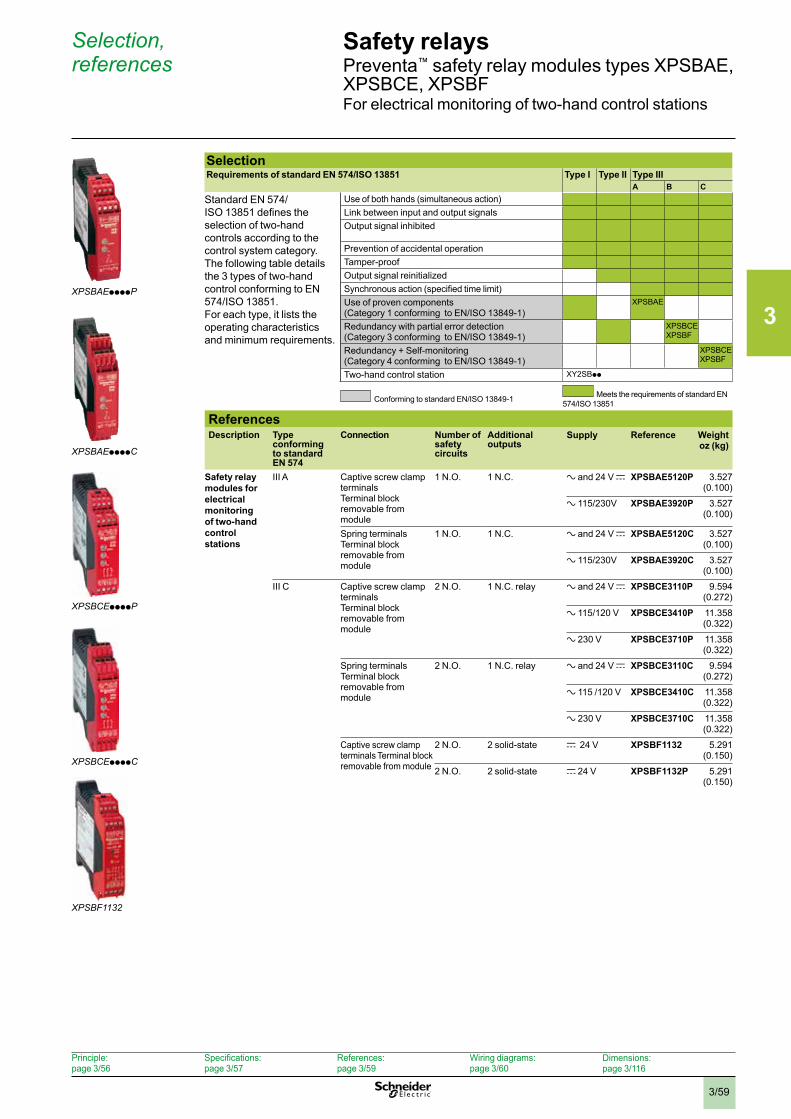
3
3/59
Safety relaysPreventa™ safety relay modules types XPSBAE, XPSBCE, XPSBFFor electrical monitoring of two-hand control stations
Selection, references
Principle: page 3/56
Specifications: page 3/57
References: page 3/59
Wiring diagrams: page 3/60
Dimensions:page 3/116
SelectionRequirements of standard EN 574/ISO 13851 Type I Type II Type III
A B CStandard EN 574/ISO 13851 defines the selection of two-hand controls according to the control system category.The following table details the 3 types of two-hand control conforming to EN 574/ISO 13851.For each type, it lists the operating characteristics and minimum requirements.
Use of both hands (simultaneous action)Link between input and output signalsOutput signal inhibited
Prevention of accidental operationTamper-proofOutput signal reinitializedSynchronous action (specified time limit)Use of proven components(Category 1 conforming to EN/ISO 13849-1)
XPSBAE
Redundancy with partial error detection (Category 3 conforming to EN/ISO 13849-1)
XPSBCEXPSBF
Redundancy + Self-monitoring(Category 4 conforming to EN/ISO 13849-1)
XPSBCEXPSBF
Two-hand control station XY2SBpp
Conforming to standard EN/ISO 13849-1 Meets the requirements of standard EN 574/ISO 13851
ReferencesDescription Type
conforming to standard EN 574
Connection Number of safety circuits
Additional outputs
Supply Reference Weight oz (kg)
Safety relay modules for electrical monitoring of two-hand control stations
III A Captive screw clamp terminals Terminal block removable from module
1 N.O. 1 N.C. a and 24 V c XPSBAE5120P 3.527 (0.100)
a 115/230V XPSBAE3920P 3.527 (0.100)
Spring terminalsTerminal block removable from module
1 N.O. 1 N.C. a and 24 V c XPSBAE5120C 3.527 (0.100)
a 115/230V XPSBAE3920C 3.527 (0.100)
III C Captive screw clamp terminals Terminal block removable from module
2 N.O. 1 N.C. relay a and 24 V c XPSBCE3110P 9.594 (0.272)
a 115/120 V XPSBCE3410P 11.358 (0.322)
a 230 V XPSBCE3710P 11.358 (0.322)
Spring terminalsTerminal block removable from module
2 N.O. 1 N.C. relay a and 24 V c XPSBCE3110C 9.594 (0.272)
a 115 /120 V XPSBCE3410C 11.358 (0.322)
a 230 V XPSBCE3710C 11.358 (0.322)
Captive screw clamp terminals Terminal block removable from module
2 N.O. 2 solid-state c 24 V XPSBF1132 5.291 (0.150)
2 N.O. 2 solid-state c 24 V XPSBF1132P 5.291 (0.150)
XPSBCEppppP
XPSBCEppppC
XPSBF1132
XPSBAEppppP
XPSBAEppppC
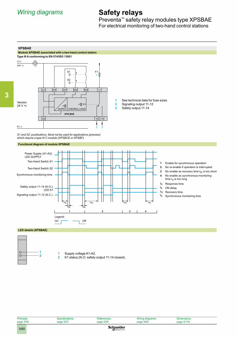
3
3/60
Safety relaysPreventa™ safety relay modules type XPSBAEFor electrical monitoring of two-hand control stations
Wiring diagrams
Principle: page 3/56
Specifications: page 3/57
References: page 3/59
Wiring diagrams: page 3/60
Dimensions:page 3/116
XPSBAEModule XPSBAE associated with a two-hand control station
Type III A conforming to EN 574/ISO 13851
S1 and S2: pushbuttons . Must not be used for applications (presses) which require a type III C module (XPSBCE or XPSBF) .
Functional diagram of module XPSBAE
LED details (XPSBAE)
1 Supply voltage A1-A2.2 K1 status (N.O. safety output 11-14 closed).
12
F0
(1)
N (–)
XPS-BAE
11
12
A1 S11 S11 S12 S13
A2
L(+)
F11
2 3
14
24V z
K1
SUPPLY CONTROL-LOGIC
S2
S1
Version24 V z
1 See technical data for fuse sizes2 Signaling output 11-123 Safety output 11-14
<tS >tW <tW >tS
<tE <tR
4321
Power Supply (A1-A2), LED SUPPLY
Two-Hand Switch S1
Two-Hand Switch S2
Synchronous monitoring time
Safety output 11-14 (N.O.),LED K1
Signaling output 11-12 (N.C.)
1 Enable for synchronous operation2 No re-enable if operation is interrupted3 No enable as recovery time tW is too short4 No enable as synchronous monitoring
time tS is too longtR Response timetE ON delaytW Recovery timetS Synchronous monitoring time
On OffLegend:
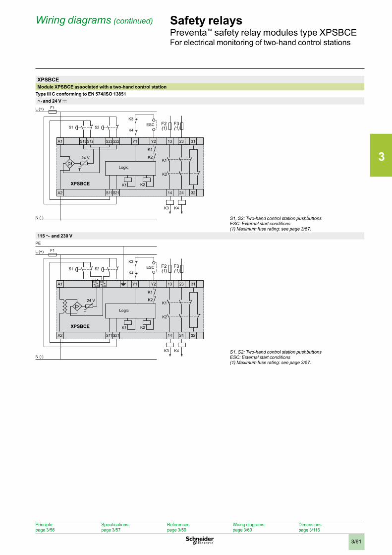
3
3/61
Safety relaysPreventa™ safety relay modules type XPSBCEFor electrical monitoring of two-hand control stations
Wiring diagrams (continued)
Principle: page 3/56
Specifications: page 3/57
References: page 3/59
Wiring diagrams: page 3/60
Dimensions:page 3/116
XPSBCEModule XPSBCE associated with a two-hand control station
Type III C conforming to EN 574/ISO 13851a and 24 V c
Logic
S1, S2: Two-hand control station pushbuttonsESC: External start conditions(1) Maximum fuse rating: see page 3/57 .
115 a and 230 V
A1 S13
S2
23 31Y2 13
A2 S11 S21 14 24 32
S12S22 S23 Y1
F1L (+)
PE
N (-)
T
ESCS1
K4
K4
K3
K3
K2
K2
K1
K2
K1
K1
24 V
XPSBCE
(1) (1)
t
Logic
S1, S2: Two-hand control station pushbuttonsESC: External start conditions(1) Maximum fuse rating: see page 3/57 .
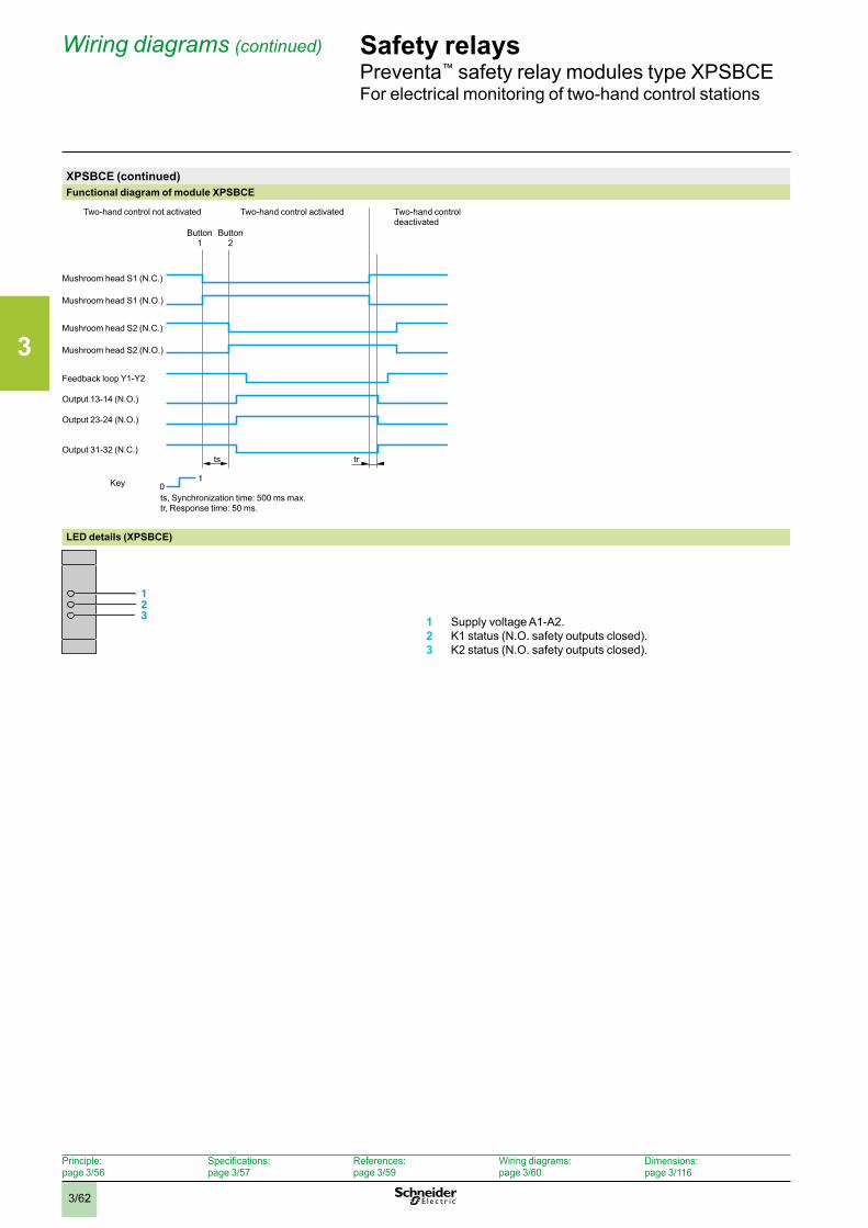
3
3/62
Safety relaysPreventa™ safety relay modules type XPSBCEFor electrical monitoring of two-hand control stations
Wiring diagrams (continued)
Principle: page 3/56
Specifications: page 3/57
References: page 3/59
Wiring diagrams: page 3/60
Dimensions:page 3/116
XPSBCE (continued)Functional diagram of module XPSBCE
10
trts
Key
Button 1
Two-hand control not activated Two-hand control activated Two-hand control deactivated
Button 2
Mushroom head S1 (N.C.)
Mushroom head S1 (N.O.)
Mushroom head S2 (N.C.)
Mushroom head S2 (N.O.)
Feedback loop Y1-Y2
Output 13-14 (N.O.)
Output 23-24 (N.O.)
Output 31-32 (N.C.)
ts, Synchronization time: 500 ms max.tr, Response time: 50 ms.
LED details (XPSBCE)
123 1 Supply voltage A1-A2.
2 K1 status (N.O. safety outputs closed).3 K2 status (N.O. safety outputs closed).
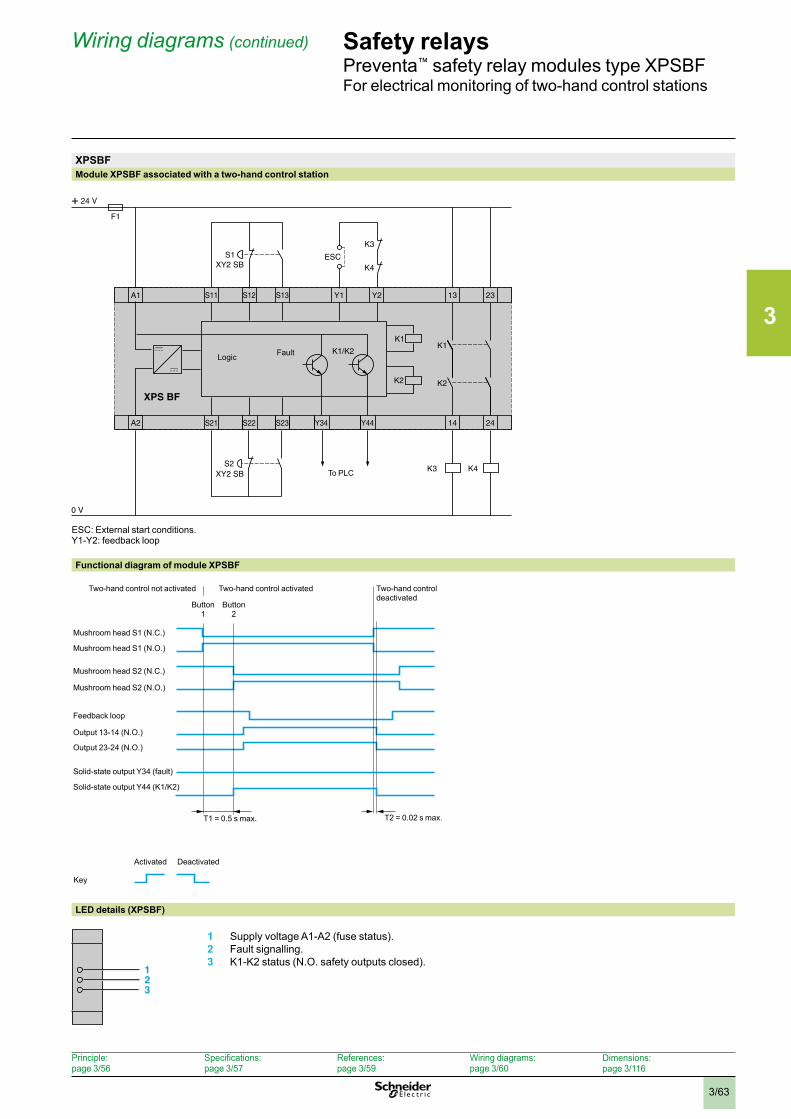
3
3/63
Safety relaysPreventa™ safety relay modules type XPSBFFor electrical monitoring of two-hand control stations
Wiring diagrams (continued)
XPSBFModule XPSBF associated with a two-hand control station
ESC: External start conditions. Y1-Y2: feedback loop
Functional diagram of module XPSBF
LED details (XPSBF)
1 Supply voltage A1-A2 (fuse status).2 Fault signalling.3 K1-K2 status (N.O. safety outputs closed).
Button1
Button2
Two-hand control deactivated
Two-hand control activatedTwo-hand control not activated
Mushroom head S1 (N.O.)
Mushroom head S1 (N.C.)
Mushroom head S2 (N.C.)
Mushroom head S2 (N.O.)
Feedback loop
Output 13-14 (N.O.)
Output 23-24 (N.O.)
Solid-state output Y34 (fault)
Key
T1 = 0.5 s max. T2 = 0.02 s max.
Solid-state output Y44 (K1/K2)
Activated Deactivated
A1 S12 23Y2 13
A2 S22 S23 Y34 Y44S21 14 24
S13S11 Y1
F1
K2
K1
K1/K2K1
K2
K4K3
K1/K2
K3
K4ESCS1
XY2 SB
XY2 SB S2
XPS BF
To PLC
FaultLogic
123
Principle: page 3/56
Specifications: page 3/57
References: page 3/59
Wiring diagrams: page 3/60
Dimensions:page 3/116
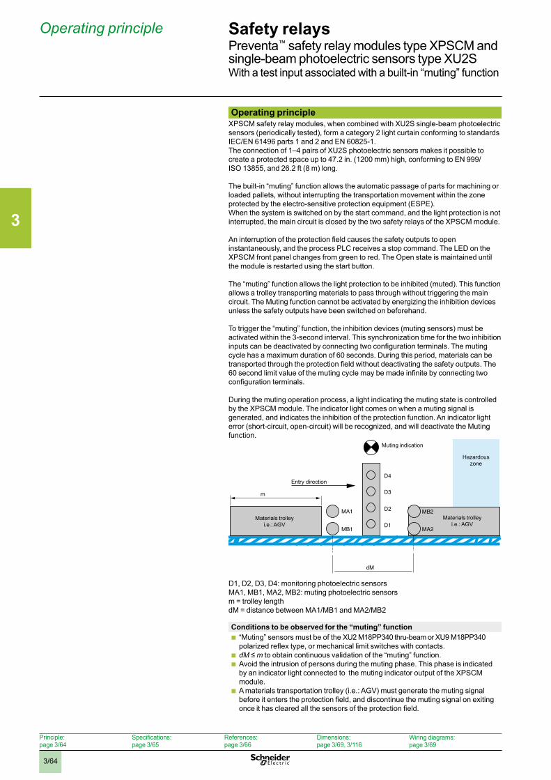
3
3/64
Safety relaysPreventa™ safety relay modules type XPSCM and single-beam photoelectric sensors type XU2SWith a test input associated with a built-in “muting” function
Operating principleXPSCM safety relay modules, when combined with XU2S single-beam photoelectric sensors (periodically tested), form a category 2 light curtain conforming to standards IEC/EN 61496 parts 1 and 2 and EN 60825-1.The connection of 1–4 pairs of XU2S photoelectric sensors makes it possible to create a protected space up to 47.2 in. (1200 mm) high, conforming to EN 999/ISO 13855, and 26.2 ft (8 m) long.
The built-in “muting” function allows the automatic passage of parts for machining or loaded pallets, without interrupting the transportation movement within the zone protected by the electro-sensitive protection equipment (ESPE).When the system is switched on by the start command, and the light protection is not interrupted, the main circuit is closed by the two safety relays of the XPSCM module.
An interruption of the protection field causes the safety outputs to open instantaneously, and the process PLC receives a stop command. The LED on the XPSCM front panel changes from green to red. The Open state is maintained until the module is restarted using the start button.
The “muting” function allows the light protection to be inhibited (muted). This function allows a trolley transporting materials to pass through without triggering the main circuit. The Muting function cannot be activated by energizing the inhibition devices unless the safety outputs have been switched on beforehand.
To trigger the “muting” function, the inhibition devices (muting sensors) must be activated within the 3-second interval. This synchronization time for the two inhibition inputs can be deactivated by connecting two configuration terminals. The muting cycle has a maximum duration of 60 seconds. During this period, materials can be transported through the protection field without deactivating the safety outputs. The 60 second limit value of the muting cycle may be made infinite by connecting two configuration terminals.
During the muting operation process, a light indicating the muting state is controlled by the XPSCM module. The indicator light comes on when a muting signal is generated, and indicates the inhibition of the protection function. An indicator light error (short-circuit, open-circuit) will be recognized, and will deactivate the Muting function.
D1, D2, D3, D4: monitoring photoelectric sensorsMA1, MB1, MA2, MB2: muting photoelectric sensorsm = trolley lengthdM = distance between MA1/MB1 and MA2/MB2
Conditions to be observed for the “muting” function b “Muting” sensors must be of the XU2 M18PP340 thru-beam or XU9 M18PP340 polarized reflex type, or mechanical limit switches with contacts.
b dM ≤ m to obtain continuous validation of the “muting” function. b Avoid the intrusion of persons during the muting phase. This phase is indicated by an indicator light connected to the muting indicator output of the XPSCM module.
b A materials transportation trolley (i.e.: AGV) must generate the muting signal before it enters the protection field, and discontinue the muting signal on exiting once it has cleared all the sensors of the protection field.
Operating principle
m
dM
MB1
MA1
D4
D2
D3
D1MA2
MB2
Entry direction
Muting indication
Hazardous zone
Materials trolleyi.e.: AGV
Materials trolleyi.e.: AGV
Principle: page 3/64
Specifications: page 3/65
References: page 3/66
Dimensions:page 3/69, 3/116
Wiring diagrams:page 3/69
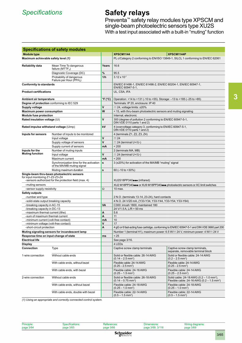
3
3/65
Safety relaysPreventa™ safety relay modules type XPSCM and single-beam photoelectric sensors type XU2SWith a test input associated with a built-in “muting” function
Specifications of safety modulesModule type XPSCM1144 XPSCM1144P
Maximum achievable safety level (1) PL c/Category 2 conforming to EN/ISO 13849-1, SILCL 1 conforming to EN/IEC 62061
Reliability data Mean Time To dangerous failure (MTTFd)
Years 16.6
Diagnostic Coverage (DC) % 95.5Probability of dangerous Failure per Hour (PFHd)
1/h 3.12 x 10⁻⁷
Conformity to standards EN/IEC 61496-1, EN/IEC 61496-2, EN/IEC 60204-1, EN/IEC 60947-1, EN/IEC 60947-5-1,
Product certifications UL, CSA, IFA
Ambient air temperature °F (°C) Operation: +14 to +131 (-10 to +55). Storage: –13 to +185 (–25 to +85)Degree of protection conforming to IEC 529 Terminals: IP 20, enclosure: IP 40Supply voltage V c 24, voltage limits: ±20%Maximum power consumption W < 15, with thru-beam photoelectric sensors and muting signalingModule fuse protection Internal, electronicRated insulation voltage (Ui) V 300 (degree of pollution 2 conforming to EN/IEC 60947-5-1,
DIN VDE 0110 parts 1 and 2)Rated impulse withstand voltage (Uimp) kV 4 (overvoltage category 3, conforming to EN/IEC 60947-5-1,
DIN VDE 0110 parts 1 and 2)Inputs for sensors Number of inputs to be monitored 4 (terminals Z1, Z2, Z3, Z4)
Input voltage V c 24Supply voltage of sensors V c 24 (terminal U+/U-)Supply current of sensors mA < 200
Inputs for the Muting function
Number of muting inputs 2 (terminals MA, MB)Input voltage V c 24 (terminal U+/U-)Maximum current mA < 200Synchronization time for the activation of the MA/MB muting signal
s 3 (±20%) for activation of the MA/MB “muting” signal
Muting maximum duration s 60 (–10 to +30%)Single-beam thru-beam photoelectric sensors for input monitoring Z1-Z2-Z3-Z4
- sensors authorized for the protection field (max. 4) XU2S18PP340ppp (infrared)- muting sensors XU2 M18PP340ppp or XU9 M18PP340ppp photoelectric sensors or XC limit switches- sensor supply resistivity W 10 max.
Safety outputs- number and type 2 N.O. (terminals 13-14, 23-24), hard contacts- solid-state output breaking capacity 4 N.O. 24 V/20 mA, (Y33-Y34, Y33-Y44, Y33-Y54, Y33-Y64)- breaking capacity in AC-15 VA C300: inrush 1800, maintained 180- breaking capacity in DC-13 24 V/1.5 A, L/R = 50 ms- maximum thermal current (Ithe) A 5.6- sum of maximum thermal current A 11- minimum current (volt-free contact) mA 10- minimum voltage (volt-free contact) V 17- short-circuit protection A 4 gG or 6 fast-acting fuse cartridge, conforming to EN/IEC 60947-5-1 and DIN VDE 0660 part 200
Muting signaling sensors for incandescent lamp Number 1 (terminal H1), maximum power: 6.5 W/c 24 V, minimum power: 4 W/c 24 VResponse time on input change of state ms < 25Electrical life See page 3/16.Display 4 LEDsConnection Type Captive screw clamp terminals Captive screw clamp terminals,
separate, removable terminal block1-wire connection Without cable ends Solid or flexible cable: 26-14 AWG
(0.14 – 2.5 mm2)Solid or flexible cable: 24-14 AWG (0.2 – 2.5 mm2)
With cable ends, without bezel Flexible cable: 24-14 AWG (0.25 – 2.5 mm2)
Flexible cable: 24-14 AWG (0.25 – 2.5 mm2)
With cable ends, with bezel Flexible cable: 24-16 AWG (0.25 – 1.5 mm2)
Flexible cable: 24-14 AWG (0.25 – 2.5 mm2)
2-wire connection Without cable ends Solid or flexible cable: 26-18 AWG (0.14 – 0.75 mm2)
Solid cable: 24-18 AWG (0.2 – 1.0 mm2), Flexible cable: 24-16 AWG (0.2 – 1.5 mm2)
With cable ends, without bezel Flexible cable: 24-18 AWG (0.25 – 1.0 mm2)
Flexible cable: 24-18 AWG (0.25 – 1.0 mm2)
With cable ends, double with bezel Flexible cable: 22-14 AWG (0.5 – 1.5 mm2)
Flexible cable: 22-14 AWG (0.5 – 1.5 mm2)
(1) Using an appropriate and correctly connected control system .
Specifications
Principle: page 3/64
Specifications: page 3/65
References: page 3/66
Dimensions:page 3/69, 3/116
Wiring diagrams:page 3/69
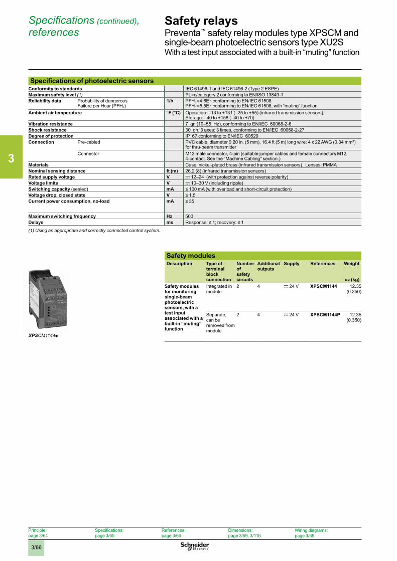
3
3/66
Safety relaysPreventa™ safety relay modules type XPSCM and single-beam photoelectric sensors type XU2SWith a test input associated with a built-in “muting” function
Safety modulesDescription Type of
terminal block connection
Number of safety circuits
Additional outputs
Supply References Weight
oz (kg)Safety modules for monitoring single-beam photoelectric sensors, with a test input associated with a built-in “muting” function
Integrated in module
2 4 c 24 V XPSCM1144 12.35 (0.350)
Separate, can be removed from module
2 4 c 24 V XPSCM1144P 12.35 (0.350)
XPSCM1144p
Specifications (continued), references
Specifications of photoelectric sensorsConformity to standards IEC 61496-1 and IEC 61496-2 (Type 2 ESPE) Maximum safety level (1) PL=c/category 2 conforming to EN/ISO 13849-1Reliability data Probability of dangerous
Failure per Hour (PFHd)1/h PFHd =4.6E-7 conforming to EN/IEC 61508
PFHd =5.5E-7 conforming to EN/IEC 61508, with “muting” functionAmbient air temperature °F (°C) Operation: –13 to +131 (–25 to +55) (infrared transmission sensors),
Storage: –40 to +158 (–40 to +70) Vibration resistance 7 gn (10–55 Hz), conforming to EN/IEC 60068-2-6Shock resistance 30 gn, 3 axes: 3 times, conforming to EN/IEC 60068-2-27Degree of protection IP 67 conforming to EN/IEC 60529 Connection Pre-cabled PVC cable, diameter 0.20 in. (5 mm), 16.4 ft (5 m) long wire: 4 x 22 AWG (0.34 mm²)
for thru-beam transmitterConnector M12 male connector, 4-pin (suitable jumper cables and female connectors M12,
4-contact. See the "Machine Cabling" section.)Materials Case: nickel-plated brass (infrared transmission sensors). Lenses: PMMANominal sensing distance ft (m) 26.2 (8) (infrared transmission sensors)Rated supply voltage V c 12–24 (with protection against reverse polarity)Voltage limits V c 10–30 V (including ripple)Switching capacity (sealed) mA ≤ 100 mA (with overload and short-circuit protection)Voltage drop, closed state V ≤ 1.5 Current power consumption, no-load mA ≤ 35
Maximum switching frequency Hz 500Delays ms Response: ≤ 1; recovery: ≤ 1
(1) Using an appropriate and correctly connected control system .
Principle: page 3/64
Specifications: page 3/65
References: page 3/66
Dimensions:page 3/69, 3/116
Wiring diagrams:page 3/69
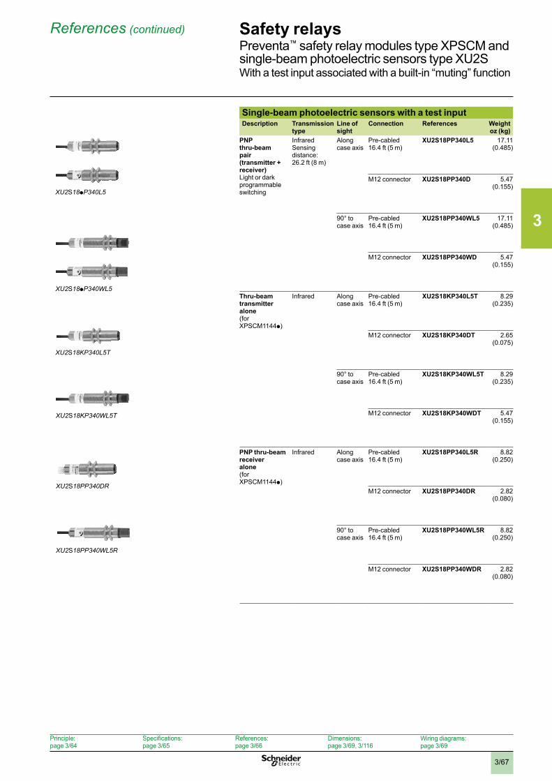
3
3/67
Safety relaysPreventa™ safety relay modules type XPSCM and single-beam photoelectric sensors type XU2SWith a test input associated with a built-in “muting” function
Single-beam photoelectric sensors with a test inputDescription Transmission
typeLine of sight
Connection References Weightoz (kg)
PNP thru-beam pair (transmitter + receiver)Light or dark programmable switching
InfraredSensing distance: 26.2 ft (8 m)
Along case axis
Pre-cabled 16.4 ft (5 m)
XU2S18PP340L5 17.11 (0.485)
M12 connector XU2S18PP340D 5.47 (0.155)
90° to case axis
Pre-cabled 16.4 ft (5 m)
XU2S18PP340WL5 17.11 (0.485)
M12 connector XU2S18PP340WD 5.47 (0.155)
Thru-beam transmitter alone(for XPSCM1144p)
Infrared Along case axis
Pre-cabled 16.4 ft (5 m)
XU2S18KP340L5T 8.29 (0.235)
M12 connector XU2S18KP340DT 2.65 (0.075)
90° to case axis
Pre-cabled 16.4 ft (5 m)
XU2S18KP340WL5T 8.29 (0.235)
M12 connector XU2S18KP340WDT 5.47 (0.155)
PNP thru-beam receiver alone(for XPSCM1144p)
Infrared Along case axis
Pre-cabled 16.4 ft (5 m)
XU2S18PP340L5R 8.82 (0.250)
M12 connector XU2S18PP340DR 2.82 (0.080)
90° to case axis
Pre-cabled 16.4 ft (5 m)
XU2S18PP340WL5R 8.82 (0.250)
M12 connector XU2S18PP340WDR 2.82 (0.080)
XU2S18pP340L5
XU2S18pP340WL5
XU2S18KP340WL5T
XU2S18KP340L5T
XU2S18PP340DR
XU2S18PP340WL5R
References (continued)
Principle: page 3/64
Specifications: page 3/65
References: page 3/66
Dimensions:page 3/69, 3/116
Wiring diagrams:page 3/69
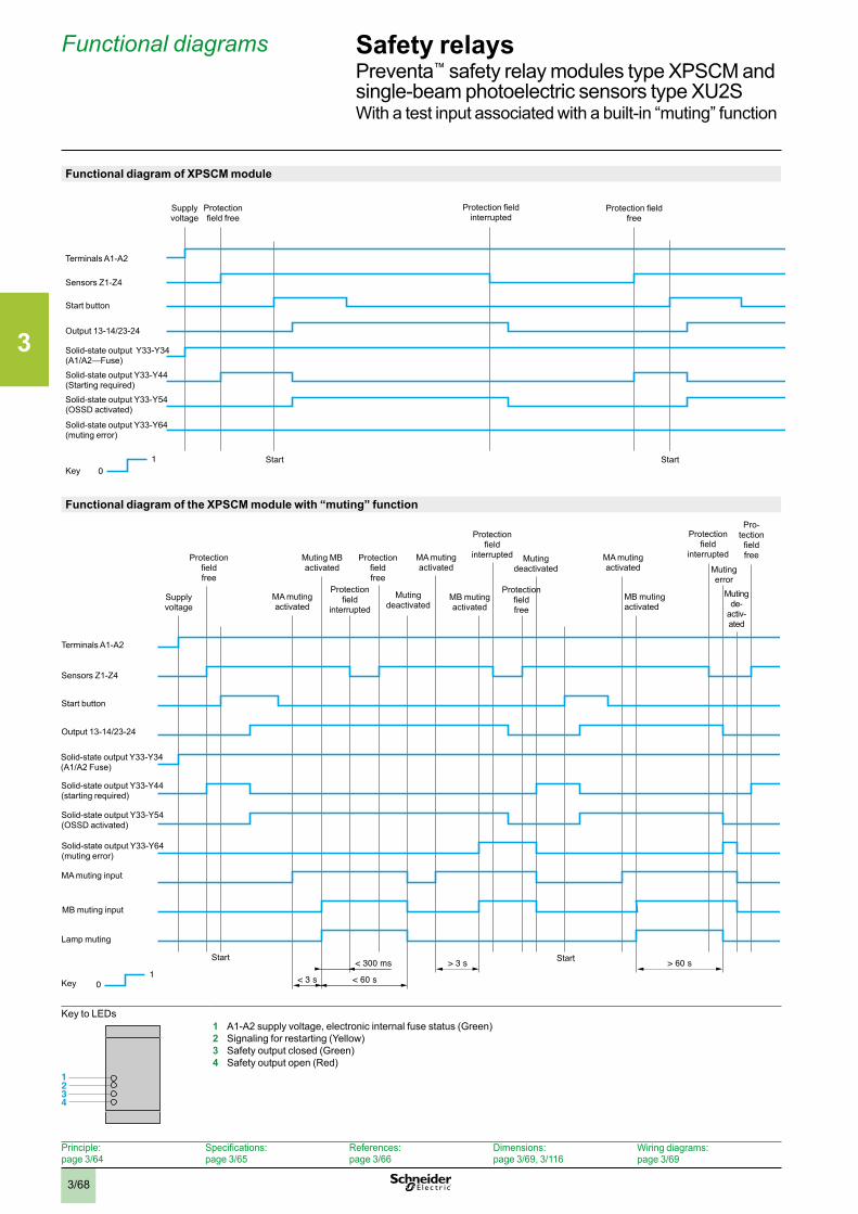
3
3/68
Safety relaysPreventa™ safety relay modules type XPSCM and single-beam photoelectric sensors type XU2SWith a test input associated with a built-in “muting” function
Functional diagram of XPSCM module
Functional diagram of the XPSCM module with “muting” function
Key to LEDs1 A1-A2 supply voltage, electronic internal fuse status (Green)2 Signaling for restarting (Yellow)3 Safety output closed (Green)4 Safety output open (Red)
1 0 < 3 s
> 3 s
< 60 s
> 60 s< 300 ms
Key
Terminals A1-A2
Sensors Z1-Z4
Start button
Output 13-14/23-24
Solid-state output Y33-Y54 (OSSD activated)
Supplyvoltage
Protection field free
MA muting activated
Muting MB activated
Protection field
interrupted
Protection field free
Muting deactivated
MA muting activated
MB muting activated
Protection field free
Muting deactivated
MA muting activated
MB muting activated
Muting error
Muting de-
activ-ated
Start Start
Solid-state output Y33-Y34 (A1/A2 Fuse)
Solid-state output Y33-Y44 (starting required)
Solid-state output Y33-Y64 (muting error)
MA muting input
MB muting input
Lamp muting
1234
Functional diagrams
1 0
Protectionfield free
Supplyvoltage
Key
Terminals A1-A2
Sensors Z1-Z4
Start button
Output 13-14/23-24
Solid-state output Y33-Y34 (A1/A2—Fuse)
Solid-state output Y33-Y64 (muting error)
Protection field interrupted
Protection field free
Solid-state output Y33-Y44 (Starting required)
Solid-state output Y33-Y54 (OSSD activated)
Start Start
Protection field
interrupted
Protection field
interrupted
Pro-tection field free
Principle: page 3/64
Specifications: page 3/65
References: page 3/66
Dimensions:page 3/69, 3/116
Wiring diagrams:page 3/69
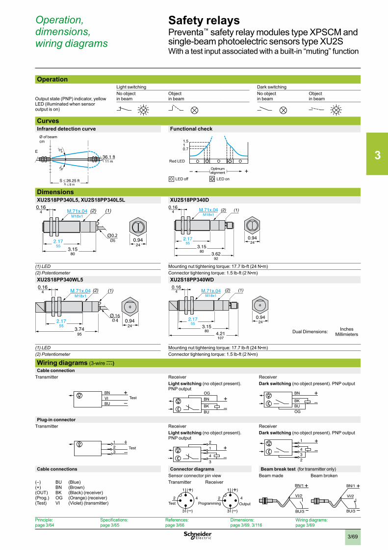
3
3/69
Safety relaysPreventa™ safety relay modules type XPSCM and single-beam photoelectric sensors type XU2SWith a test input associated with a built-in “muting” function
OperationLight switching Dark switching
Output state (PNP) indicator, yellow LED (illuminated when sensor output is on)
No object in beam
Object in beam
No object in beam
Object in beam
CurvesInfrared detection curve Functional check
DimensionsXU2S18PP340L5, XU2S18PP340L5L XU2S18PP340D
(1) LED Mounting nut tightening torque: 17.7 lb-ft (24 N•m)(2) Potentiometer Connector tightening torque: 1.5 lb-ft (2 N•m)XU2S18PP340WL5 XU2S18PP340WD
(1) LED Mounting nut tightening torque: 17.7 lb-ft (24 N•m)(2) Potentiometer Connector tightening torque: 1.5 lb-ft (2 N•m)
Wiring diagrams (3-wire c)Cable connection
Transmitter Receiver ReceiverLight switching (no object present). PNP output
Dark switching (no object present). PNP output
Plug-in connectorTransmitter Receiver Receiver
Light switching (no object present). PNP output
Dark switching (no object present). PNP output
Cable connections Connector diagrams Beam break test (for transmitter only)Sensor connector pin view Beam made Beam broken
(–)(+)(OUT)(Prog.)(Test)
BUBNBKOGVI
(Blue)(Brown)(Black) (receiver)(Orange) (receiver)(Violet) (transmitter)
Transmitter Receiver
36.1 ft11 m
26.25 ft
Ø of beamcm
E 0.711.5
+–
Red LED
Optimum alignment
LED off LED on
0.164 (1)M.71x.04
M18x1(2)
0.2
3.1580
2.1755
0.9424
(1)(2)
0.9424
M.71x.04M18x1
0.164
2.1755
3.6292
3.1580
(1)(2)0.164 M.71x.04
M18x1
.1642.17
550.94
243.74
95
(1)(2)0.164 M.71x.04
M18x1
3.1580 4.21
107
2.1755
0.9424
BN
BU
+
–VI Test
OGBN
BKBU
+–�
BN
BUOG
BK
+–
1
32 Test +
–34
12 +
–234
1
+
–
BN/1
VI/2
BU/3
+
–
BN/1
VI/2
BU/3
1 (+)
3 (–)
42Test
1 (+)
3 (–)
42Output
Operation, dimensions, wiring diagrams
InchesMillimietersDual Dimensions:
Programming
Principle: page 3/64
Specifications: page 3/65
References: page 3/66
Dimensions:page 3/69, 3/116
Wiring diagrams:page 3/69
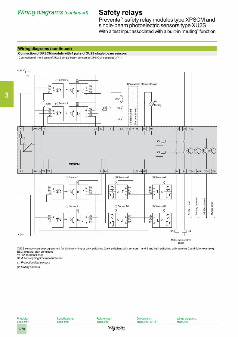
3
3/70
Safety relaysPreventa™ safety relay modules type XPSCM and single-beam photoelectric sensors type XU2SWith a test input associated with a built-in “muting” function
Wiring diagrams (continued)Connection of XPSCM module with 4 pairs of XU2S single-beam sensors
(Connection of 1 to 4 pairs of XU2 S single-beam sensors to XPS CM, see page 3/71)
XU2S sensors can be programmed for light switching or dark switching (dark switching with sensors 1 and 3 and light switching with sensors 2 and 4, for example).ESC: external start conditions Y1-Y2: feedback loop.STM: for stopping time measurement.(1) Protection field sensors(2) Muting sensors
T1A1 U U
T2U U T3A2 Z4 UV MA MBZ2
24 V
N ( )
Y2
Y342414
H1UVZ1 Z3
XPSCM
F1
Y33Y1 Y4 Y5Y3
K1
BNBUBK
BN
OG
OG
BUVI
BNBUVI
BNBUBK
K2
K3 K4
2313
Y64Y54
H1STM
S1 K3
K4
A
A
A
A
BNBUBK
BN
OG
OG
BUVI
BNBUVI
BNBUBK
Y44
ESC
Muting
A
A
BNBUBK
OG
OG
OG
OG
BNBUBK
BNBUBK
BNBUBK
A
A
T
(1) Sensor 3
(1) Sensor 1
Start
Deactivation of time intervals
3 s
deac
tivat
ed
60 s
dea
ctiv
ated
A1/
A2—
Fuse
(1) Sensor 2
(1) Sensor 4
(2) Sensor A1
(2) Sensor B1 (2) Sensor B2
(2) Sensor A2
Sta
rting
requ
ired
Mut
ing
erro
r
OS
SD
act
ivat
ed
Motor main control object
Wiring diagrams (continued)
Principle: page 3/64
Specifications: page 3/65
References: page 3/66
Dimensions:page 3/69, 3/116
Wiring diagrams:page 3/69
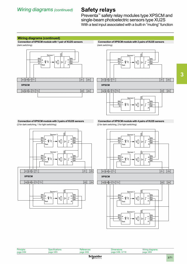
3
3/71
Safety relaysPreventa™ safety relay modules type XPSCM and single-beam photoelectric sensors type XU2SWith a test input associated with a built-in “muting” function
Wiring diagrams (continued)Connection of XPSCM module with 1 pair of XU2S sensors Connection of XPSCM module with 2 pairs of XU2S sensors
(dark switching) (dark switching)
Connection of XPSCM module with 3 pairs of XU2S sensors Connection of XPSCM module with 4 pairs of XU2S sensors(2 for dark switching, 1 for light switching) (2 for dark switching, 2 for light switching)
T1A1 U+ U–
T2U+ U T3A2 Z4Z2
Z1 Z3
XPSCM
BNBUBK
BNO
GBUVI
+–
+–A
–
Sensor 1
Test
T1A1 U+ U–
T2U+ U– T3A2 Z4Z2
Z1 Z3
XPSCM
BNBUBK
BN
OG
BUVI
+–
+–
+–A
BNBUBK
BN
OG
BUVI
+–A
Sensor 1
Test
Sensor 2
T1A1 U+ U–
T2U+ U– T3A2 Z4Z2
Z1 Z3
XPSCM
BNBUBK
BN
OG
OG
BUVI
BNBUVI
BNBUBK
+–
+–
+–
+–
+–
A
A
BNBUBK
BN
OG
BUVI
+–A
Sensor 3
Test
Sensor 2
Test
Sensor 1
Test
T1A1 U+ U–
T2U+ U– T3A2 Z4Z2
Z1 Z3
XPSCM
BNBUBK
BNO
GO
GBUVI
BNBUVI
BNBUBK
+–
+–
+–
+–
A
A
BNBUBK
BN
OG
OG
BUVI
BNBUVI
BNBUBK
+–
+–
+–
A
+–A
Sensor 3
Test
Sensor 2
Test
Sensor 1
Test
Sensor 4
Test
Wiring diagrams (continued)
Principle: page 3/64
Specifications: page 3/65
References: page 3/66
Dimensions:page 3/69, 3/116
Wiring diagrams:page 3/69
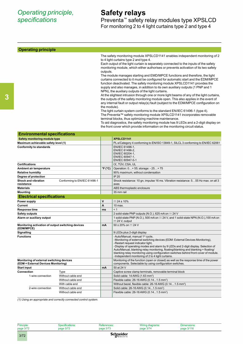
3
3/72
Safety relaysPreventa™ safety relay modules type XPSLCDFor monitoring 2 to 4 light curtains type 2 and type 4
Operating principleThe safety monitoring module XPSLCD1141 enables independent monitoring of 2 to 4 light curtains type 2 and type 4.Each output of the light curtain is separately connected to the inputs of the safety monitoring module, which either authorises or prevents activation of its two safety outputs.The module manages starting and EMD/MPCE functions and therefore, the light curtains connected to it must be configured for automatic start and the EDM/MPCE function deactivated. The safety monitoring module XPSLCD1141 provides the supply and also manages, in addition to its own auxiliary outputs (1 PNP and 1 NPN), the auxiliary outputs of the light curtains.At the slightest intrusion through one or more light beams of any of the light curtains, the outputs of the safety monitoring module open. This also applies in the event of any internal fault or output relay(s) fault (subject to the EDM/MPCE configuration on the module).The light curtain system conforms to the standard EN/IEC 61496-1 (type 4).The Preventa™ safety monitoring module XPSLCD1141 incorporates removable terminal blocks, thus optimizing machine maintenance.To aid diagnostics, the safety monitoring module has 9 LEDs and a 2-digit display on the front cover which provide information on the monitoring circuit status.
Environmental specificationsSafety monitoring module type XPSLCD1141
Maximum achievable safety level (1) PL e/Category 4 conforming to EN/ISO 13849-1, SILCL 3 conforming to EN/IEC 62061Conformity to standards EN/IEC 61496-1,
EN/IEC 61496-2,EN/IEC 60204-1,EN/IEC 60947-1,EN/IEC 60947-5-1
Certifications e, TÜV, CSA, ULAmbient air temperature °F (°C) Operation: 0…+ 55; storage: - 25…+ 75Relative humidity 95% maximum, without condensationDegree of protection IP 20Shock and vibration resistance
Conforming to EN/IEC 61496-1 Shock resistance: 10 gn, impulse 16 ms. Vibration resistance: 5…55 Hz max. on all 3 axes
Materials ABS thermoplastic enclosureMounting 35 mm rail
Electrical specificationsPower supply V c 24 ± 10%Current A 10 max.Response time ms < 1Safety outputs 2 solid-state PNP outputs (N.O.), 625 mA on c 24 VAlarm or auxiliary output 1 solid-state PNP (N.O.), 500 mA on c 24 V, and 1 solid-state NPN (N.O.),100 mA on
c 24 V, outputMonitoring activation of output switching devices (EDM/MPCE)
mA 50 ± 20% on c 24 V
Signalling 9 LEDs plus 2-digit displayFunctions - Auto/Manual, manual 1st cycle,
- Monitoring of external switching devices (EDM: External Devices Monitoring),- Restart request indicator light, - Display of operating modes and alarm by 9 LEDs and 2-digit display. Selection of Auto/Manual, blanking relay monitoring, floating/blanking and blanking + floating/blanking relay monitoring using configuration switches behind front cover of module.- Independent monitoring of 2 to 4 light curtains.
Monitoring of external switching devices(EDM = External Devices Monitoring)
Monitoring of the function (open or closed) as well as the response time of the power components. Selectable by using configuration switches.
Start input mA 50 at 24 VConnection Type Captive screw clamp terminals, removable terminal block
1-wire connection Without cable end Solid cable: 14 AWG (1.63 mm2)Without cable end Flexible cable: 26-16 AWG (0.14...1.5 mm2)With cable end Without bezel, flexible cable: 26-16 AWG (0.14…1.5 mm2)
2-wire connection Without cable end Solid cable: 26-16 AWG (0.14...1.5 mm2)Without cable end Flexible cable: 26-16 AWG (0.14...1.5 mm2)
(1) Using an appropriate and correctly connected control system .
Operating principle, specifications
Principle: page 3/72
Specifications: page 3/72
References: page 3/73
Wiring diagrams: page 3/74
Dimensions:page 3/116
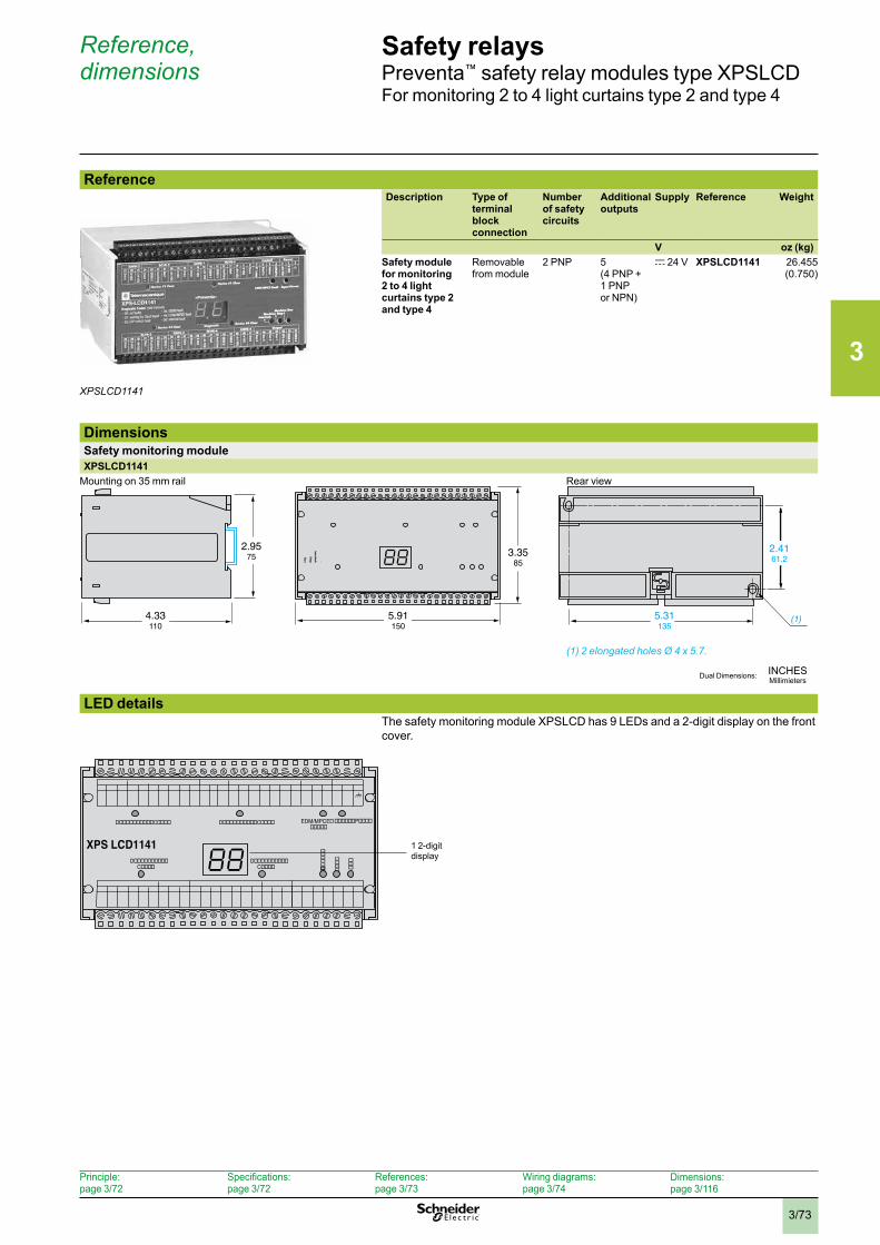
3
3/73
Safety relaysPreventa™ safety relay modules type XPSLCDFor monitoring 2 to 4 light curtains type 2 and type 4
ReferenceDescription Type of
terminal block connection
Number of safety circuits
Additional outputs
Supply Reference Weight
V oz (kg)Safety module for monitoring 2 to 4 light curtains type 2 and type 4
Removable from module
2 PNP 5 (4 PNP + 1 PNP or NPN)
c 24 V XPSLCD1141 26.455(0.750)
DimensionsSafety monitoring moduleXPSLCD1141
Mounting on 35 mm rail Rear view
(1) 2 elongated holes Ø 4 x 5 .7 .
LED detailsThe safety monitoring module XPSLCD has 9 LEDs and a 2-digit display on the front cover.
XPSLCD1141
(1)4.33110
2.9575 3.35
85
5.91150
5.31135
2.4161.2
MPCE/EDM
���
����
���������
EDM/MPCE������
D����������C����D����������C����
D����������C����
D����������C����
������P����
XPS LCD1141 1 2-digit display
Reference, dimensions
Principle: page 3/72
Specifications: page 3/72
References: page 3/73
Wiring diagrams: page 3/74
Dimensions:page 3/116
INCHESMillimietersDual Dimensions:
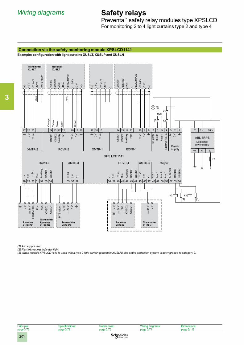
3
3/74
Safety relaysPreventa™ safety relay modules type XPSLCDFor monitoring 2 to 4 light curtains type 2 and type 4
Connection via the safety monitoring module XPSLCD1141Example: configuration with light curtains XUSLT, XUSLP and XUSLN
(1) Arc suppressor .(2) Restart request indicator light .(3) When module XPSLCD1141 is used with a type 2 light curtain (example: XUSLN), the entire protection system is downgraded to category 2 .
Wiring diagrams
Bro
wn
Whi
te
Gre
y
Viol
etYe
llow
Ora
nge
Pin
k
Bla
ck
Blu
e
Receiver XUSLT
Transmitter XUSLT
MTS
retu
rn
Run
27
XMTR-2
XPS LCD1141
0 V
c 2
4
OS
SD
1
OS
SD
2
OS
SD
1
OS
SD
2
OS
SD
1
Aux
.4
Aux
.3
Aux
.2
Aux
.1
XP
S A
ux.
OS
SD
2
OS
SD
B
OS
SD
A
c 2
4
0 V
0 V
c 2
4
OS
SD
1
OS
SD
2
c 2
4
0 V
ED
M/M
PC
E In
c 2
4
0 V
0 V
0 V
0 V
c 2
4
c 2
4
0 V
c 2
4
c 2
4
26 25 24 23 22 21 20 19 18 17 16 15 14 13 12 11 10 9 8 7 6 5 4 3 2 1
28 29 30 31 32 33 34 35 36 37 38 39 40 41 42 43 44 45 46 47 48 49 50 51 52 53 54
RCVR-2
RCVR-3 RCVR-4XMTR-3 XMTR-4
RCVR-1XMTR-1
K2
F1
N
K1
K2
L
K1
OS
SD
1
OS
SD
2
0 V
c 2
4 V
Aux
.
ABL 8RPS
N L
0 V 24 V
EDM
/MPC
E
(1)(1)
(2)
MTS
0 V
c 2
4 V
OS
SD
1
OS
SD
2
0 V
c 2
4 V
Aux
.
EDM
/MPC
E
MTS
0 V
c 2
4 V
OS
SD
2
MTS
OS
SD
1
ED
M/M
PC
E
0 V
0 V
Aux
.
0 V
0 V
OS
SD
2
OS
SD
1
(3)
Transmitter XUSLT
Receiver XUSLT
MTS
retu
rn
Run
Blu
e
Ora
nge
Yello
w
Viol
et
Gre
y
Bro
wn
Pin
k
Run
Aux
iliar
yR
un
Aux
iliar
y
Run
ST
Lam
p
Run
In
Ret
urn
Aux
iliar
yR
un
Aux
iliar
y
Run
Dedicated power supplyPower
supply
Output
Run
Run
Receiver XUSLPZ
Receiver XUSLN
Transmitter XUSLN
Transmitter Receiver XUSLPB
Transmitter XUSLPZ
MTS
retu
rn
Principle: page 3/72
Specifications: page 3/72
References: page 3/73
Wiring diagrams: page 3/74
Dimensions:page 3/116
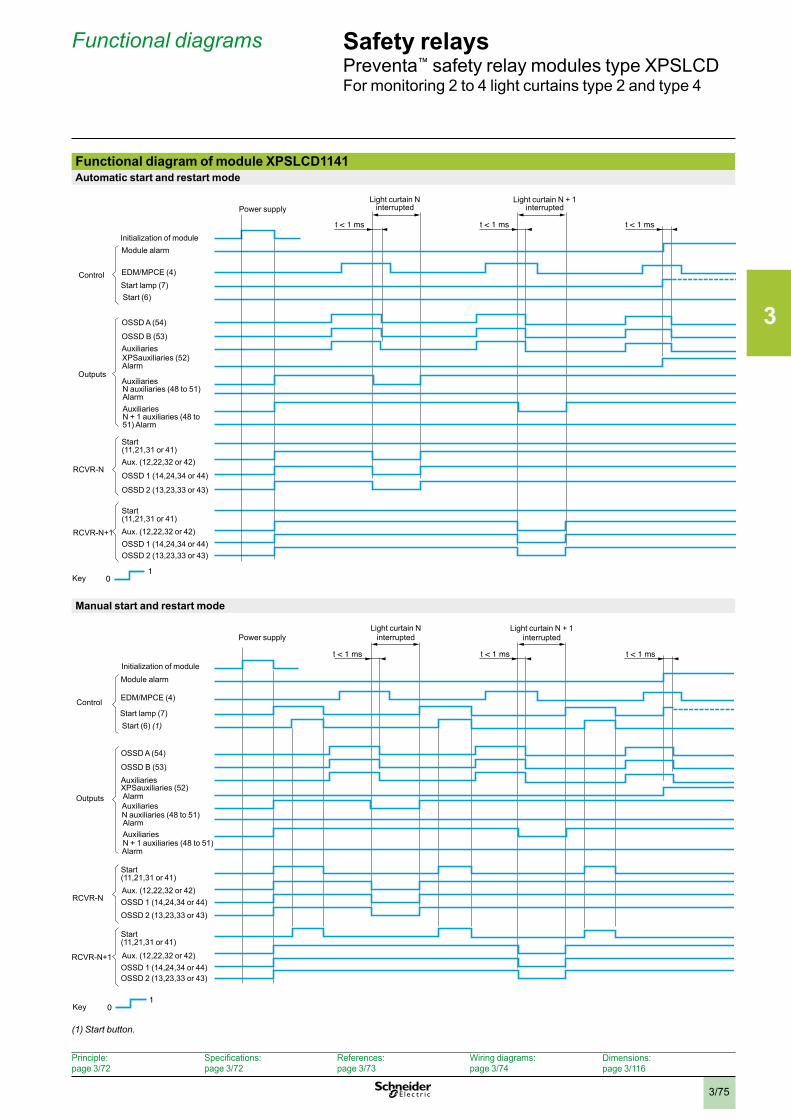
3
3/75
Safety relaysPreventa™ safety relay modules type XPSLCDFor monitoring 2 to 4 light curtains type 2 and type 4
Functional diagram of module XPSLCD1141Automatic start and restart mode
Manual start and restart mode
(1) Start button .
Functional diagrams
t < 1 ms t < 1 ms t < 1 ms
01
Key
Light curtain N interrupted
Light curtain N + 1 interrupted
Initialization of moduleModule alarm
EDM/MPCE (4)
Power supply
Start lamp (7)Start (6)
Control
OSSD A (54)
OSSD B (53)Auxiliaries
Auxiliaries
Auxiliaries
N auxiliaries (48 to 51) Alarm
Outputs
OSSD 2 (13,23,33 or 43)OSSD 1 (14,24,34 or 44)Aux. (12,22,32 or 42)
Start(11,21,31 or 41)
OSSD 2 (13,23,33 or 43)
OSSD 1 (14,24,34 or 44)
Aux. (12,22,32 or 42)
Start(11,21,31 or 41)
RCVR-N
RCVR-N+1
XPSauxiliaries (52)Alarm
N + 1 auxiliaries (48 to 51) Alarm
t < 1 ms t < 1 ms t < 1 ms
01
Key
Light curtain N interrupted
Light curtain N + 1 interrupted
Initialization of moduleModule alarm
EDM/MPCE (4)
Power supply
Start lamp (7)Start (6) (1)
Control
OSSD A (54)
OSSD B (53)AuxiliariesXPSauxiliaries (52)
AuxiliariesN auxiliaries (48 to 51)
N + 1 auxiliaries (48 to 51)
Outputs
Alarm
OSSD 2 (13,23,33 or 43)OSSD 1 (14,24,34 or 44)Aux. (12,22,32 or 42)
Start(11,21,31 or 41)
OSSD 2 (13,23,33 or 43)OSSD 1 (14,24,34 or 44)Aux. (12,22,32 or 42)
Start(11,21,31 or 41)
RCVR-N
RCVR-N+1
Auxiliaries
Alarm
Alarm
Principle: page 3/72
Specifications: page 3/72
References: page 3/73
Wiring diagrams: page 3/74
Dimensions:page 3/116
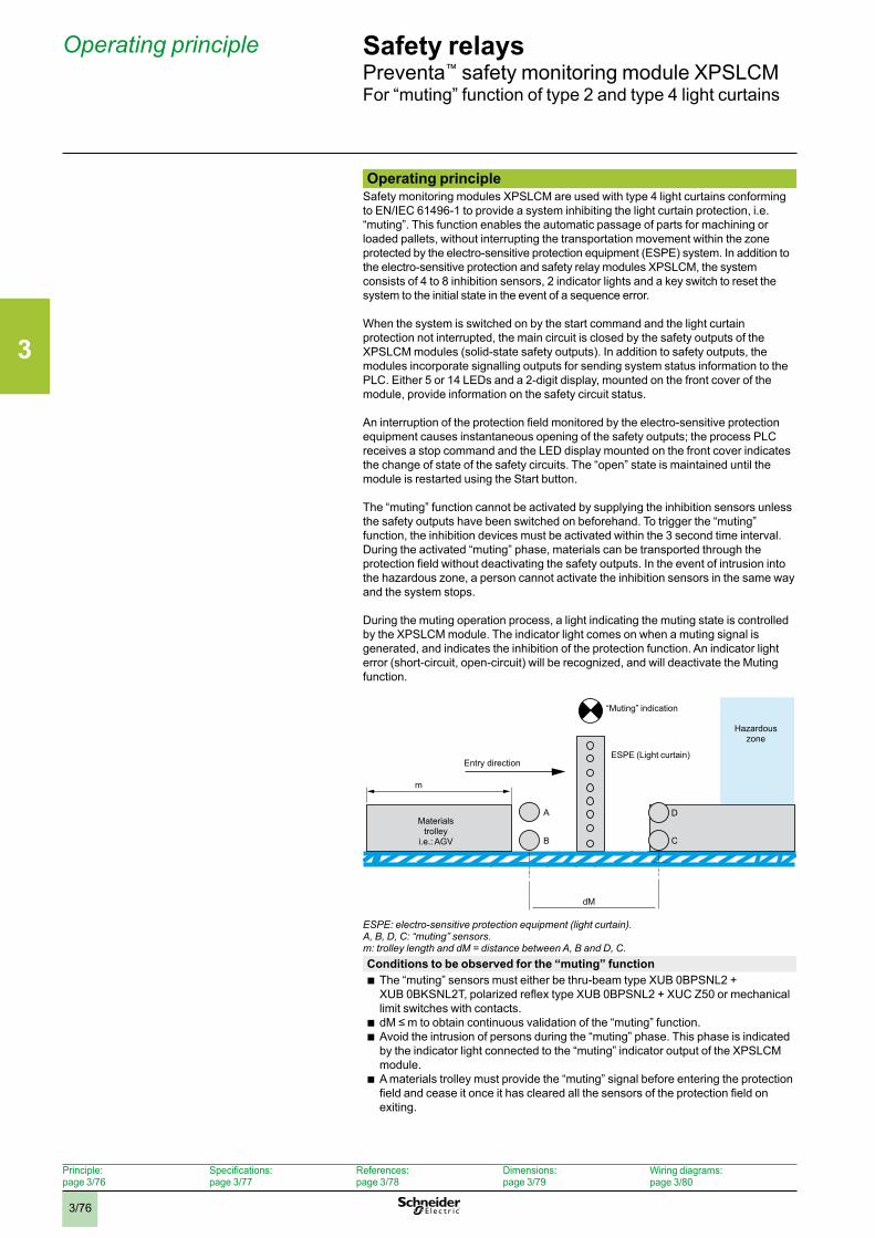
3
3/76
Safety relaysPreventa™ safety monitoring module XPSLCMFor “muting” function of type 2 and type 4 light curtains
Operating principleSafety monitoring modules XPSLCM are used with type 4 light curtains conforming to EN/IEC 61496-1 to provide a system inhibiting the light curtain protection, i.e. “muting”. This function enables the automatic passage of parts for machining or loaded pallets, without interrupting the transportation movement within the zone protected by the electro-sensitive protection equipment (ESPE) system. In addition to the electro-sensitive protection and safety relay modules XPSLCM, the system consists of 4 to 8 inhibition sensors, 2 indicator lights and a key switch to reset the system to the initial state in the event of a sequence error.
When the system is switched on by the start command and the light curtain protection not interrupted, the main circuit is closed by the safety outputs of the XPSLCM modules (solid-state safety outputs). In addition to safety outputs, the modules incorporate signalling outputs for sending system status information to the PLC. Either 5 or 14 LEDs and a 2-digit display, mounted on the front cover of the module, provide information on the safety circuit status.
An interruption of the protection field monitored by the electro-sensitive protection equipment causes instantaneous opening of the safety outputs; the process PLC receives a stop command and the LED display mounted on the front cover indicates the change of state of the safety circuits. The “open” state is maintained until the module is restarted using the Start button. The “muting” function cannot be activated by supplying the inhibition sensors unless the safety outputs have been switched on beforehand. To trigger the “muting” function, the inhibition devices must be activated within the 3 second time interval. During the activated “muting” phase, materials can be transported through the protection field without deactivating the safety outputs. In the event of intrusion into the hazardous zone, a person cannot activate the inhibition sensors in the same way and the system stops.
During the muting operation process, a light indicating the muting state is controlled by the XPSLCM module. The indicator light comes on when a muting signal is generated, and indicates the inhibition of the protection function. An indicator light error (short-circuit, open-circuit) will be recognized, and will deactivate the Muting function.
ESPE: electro-sensitive protection equipment (light curtain) .A, B, D, C: “muting” sensors .m: trolley length and dM = distance between A, B and D, C .Conditions to be observed for the “muting” function
b The “muting” sensors must either be thru-beam type XUB 0BPSNL2 + XUB 0BKSNL2T, polarized reflex type XUB 0BPSNL2 + XUC Z50 or mechanical limit switches with contacts.
b dM ≤ m to obtain continuous validation of the “muting” function. b Avoid the intrusion of persons during the “muting” phase. This phase is indicated by the indicator light connected to the “muting” indicator output of the XPSLCM module.
b A materials trolley must provide the “muting” signal before entering the protection field and cease it once it has cleared all the sensors of the protection field on exiting.
Operating principle
Principle: page 3/76
Specifications: page 3/77
References: page 3/78
Dimensions: page 3/79
Wiring diagrams:page 3/80
m
dM
B
A
C
D
Entry direction
“Muting” indication
Hazardous zone
Materials trolley
i.e.: AGV
ESPE (Light curtain)
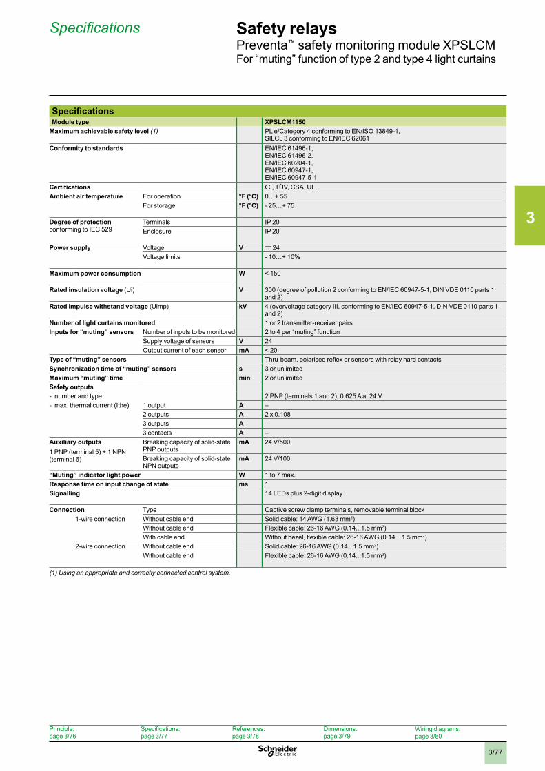
3
3/77
Safety relaysPreventa™ safety monitoring module XPSLCMFor “muting” function of type 2 and type 4 light curtains
Specifications
Principle: page 3/76
Specifications: page 3/77
References: page 3/78
Dimensions: page 3/79
Wiring diagrams:page 3/80
SpecificationsModule type XPSLCM1150
Maximum achievable safety level (1) PL e/Category 4 conforming to EN/ISO 13849-1, SILCL 3 conforming to EN/IEC 62061
Conformity to standards EN/IEC 61496-1, EN/IEC 61496-2, EN/IEC 60204-1, EN/IEC 60947-1, EN/IEC 60947-5-1
Certifications e, TÜV, CSA, ULAmbient air temperature For operation °F (°C) 0…+ 55
For storage °F (°C) - 25…+ 75
Degree of protectionconforming to IEC 529
Terminals IP 20Enclosure IP 20
Power supply Voltage V c 24Voltage limits - 10…+ 10%
Maximum power consumption W < 150
Rated insulation voltage (Ui) V 300 (degree of pollution 2 conforming to EN/IEC 60947-5-1, DIN VDE 0110 parts 1 and 2)
Rated impulse withstand voltage (Uimp) kV 4 (overvoltage category III, conforming to EN/IEC 60947-5-1, DIN VDE 0110 parts 1 and 2)
Number of light curtains monitored 1 or 2 transmitter-receiver pairsInputs for “muting” sensors Number of inputs to be monitored 2 to 4 per “muting” function
Supply voltage of sensors V 24Output current of each sensor mA < 20
Type of “muting” sensors Thru-beam, polarised reflex or sensors with relay hard contactsSynchronization time of “muting” sensors s 3 or unlimitedMaximum “muting” time min 2 or unlimitedSafety outputs- number and type 2 PNP (terminals 1 and 2), 0.625 A at 24 V- max. thermal current (Ithe) 1 output A –
2 outputs A 2 x 0.1083 outputs A –3 contacts A –
Auxiliary outputs1 PNP (terminal 5) + 1 NPN (terminal 6)
Breaking capacity of solid-state PNP outputs
mA 24 V/500
Breaking capacity of solid-state NPN outputs
mA 24 V/100
“Muting” indicator light power W 1 to 7 max.Response time on input change of state ms 1Signalling 14 LEDs plus 2-digit display
Connection Type Captive screw clamp terminals, removable terminal block1-wire connection Without cable end Solid cable: 14 AWG (1.63 mm2)
Without cable end Flexible cable: 26-16 AWG (0.14...1.5 mm2)With cable end Without bezel, flexible cable: 26-16 AWG (0.14…1.5 mm2)
2-wire connection Without cable end Solid cable: 26-16 AWG (0.14...1.5 mm2)Without cable end Flexible cable: 26-16 AWG (0.14...1.5 mm2)
(1) Using an appropriate and correctly connected control system .
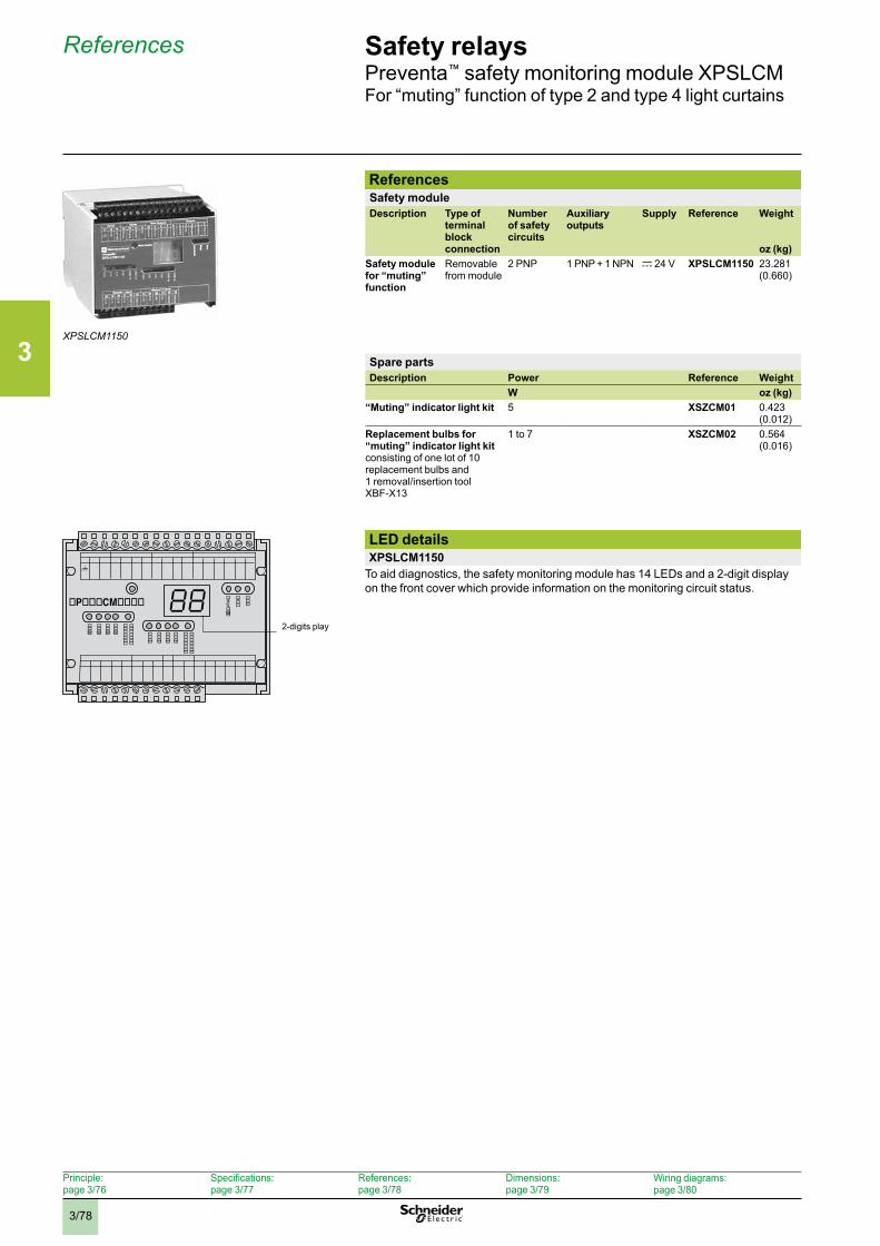
3
3/78
Safety relaysPreventa™ safety monitoring module XPSLCMFor “muting” function of type 2 and type 4 light curtains
ReferencesSafety moduleDescription Type of
terminal block connection
Number of safety circuits
Auxiliary outputs
Supply Reference Weight
oz (kg)Safety module for “muting” function
Removable from module
2 PNP 1 PNP + 1 NPN c 24 V XPSLCM1150 23.281(0.660)
Spare partsDescription Power Reference Weight
W oz (kg)“Muting” indicator light kit 5 XSZCM01 0.423
(0.012)Replacement bulbs for “muting” indicator light kitconsisting of one lot of 10 replacement bulbs and 1 removal/insertion tool XBF-X13
1 to 7 XSZCM02 0.564 (0.016)
LED detailsXPSLCM1150
To aid diagnostics, the safety monitoring module has 14 LEDs and a 2-digit display on the front cover which provide information on the monitoring circuit status.
References
XPSLCM1150
MPCE/EDM
Preventa�t��
��������������
������������
����
��������������
������������
����
���
�nter����
�P���CM����
2-digits play
Principle: page 3/76
Specifications: page 3/77
References: page 3/78
Dimensions: page 3/79
Wiring diagrams:page 3/80
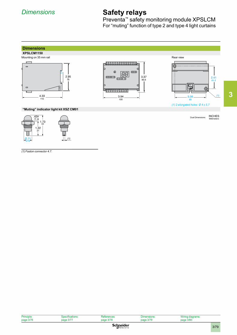
3
3/79
Safety relaysPreventa™ safety monitoring module XPSLCMFor “muting” function of type 2 and type 4 light curtains
DimensionsXPSLCM1150
Mounting on 35 mm rail Rear view
(1) 2 elongated holes Ø 4 x 5 .7
“Muting” indicator light kit XSZ CM01
(1) Faston connector 4 .7 .
Dimensions
(1)4.33110
2.9575
2.4161.2
3.3585
3.94100
3.3785.6
(1)
.4311
1.2231
1.7344
Ø.71Ø18
INCHESMillimietersDual Dimensions:
Principle: page 3/76
Specifications: page 3/77
References: page 3/78
Dimensions: page 3/79
Wiring diagrams:page 3/80
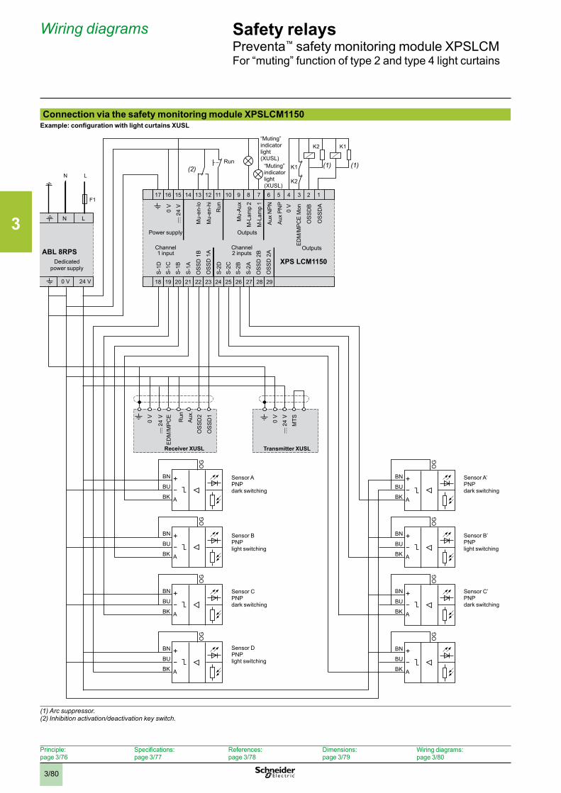
3
3/80
Connection via the safety monitoring module XPSLCM1150Example: configuration with light curtains XUSL
(1) Arc suppressor .(2) Inhibition activation/deactivation key switch .
XPS LCM1150
S-1
D
S-1
C
S-1
B
S-1
A
OS
SD
1B
OS
SD
1A
S-2
D
S-2
C
S-2
B
S-2
A
OS
SD
2B
OS
SD
2A
OS
SD
2
MTS
OS
SD
1
EDM
/MPC
E M
on
OS
SD
B
OS
SD
A
17 16 15 14 13 12 11 10 9 8 7 6 5 4 3 2 1
18 19 20 21 22 23 24 25 26 27 28
BN
OG
BU
BK
+
A
29
K2 K1
F1
N L
ABL 8RPS
N L
0 V 24 V
(1) (1)E
DM
/MP
CE
0 V 0 V
0 V
0 V
K1
K2
–
BN
OG
BU
BK
+
A
–
BN
OG
BU
BK
+
A
–
BN
OG
BU
BK
+
A
–
BN
OG
BU
BK
+
A
–
BN
OG
BU
BK
+
A
–
BN
OG
BU
BK
+
A
–
BN
OG
BU
BK
+
A
–
Transmitter XUSLReceiver XUSL
Run
Dedicated power supply
“Muting” indicator light (XUSL)
Mu-
en-lo
Mu-
en-h
i
Run
Mu-
Aux
M-L
amp
2
M-L
amp
1
Aux
NP
N
Aux
PN
P
Power supply Outputs
Channel 1 input
Channel 2 inputs
Outputs
Run
Aux
.
Sensor A PNPdark switching
Sensor B PNPlight switching
Sensor C PNPdark switching
Sensor D PNPlight switching
Sensor A’PNPdark switching
Sensor B’ PNPlight switching
Sensor C’PNPdark switching
Safety relaysPreventa™ safety monitoring module XPSLCMFor “muting” function of type 2 and type 4 light curtains
Wiring diagrams
(2)
Principle: page 3/76
Specifications: page 3/77
References: page 3/78
Dimensions: page 3/79
Wiring diagrams:page 3/80
“Muting” indicator light (XUSL)
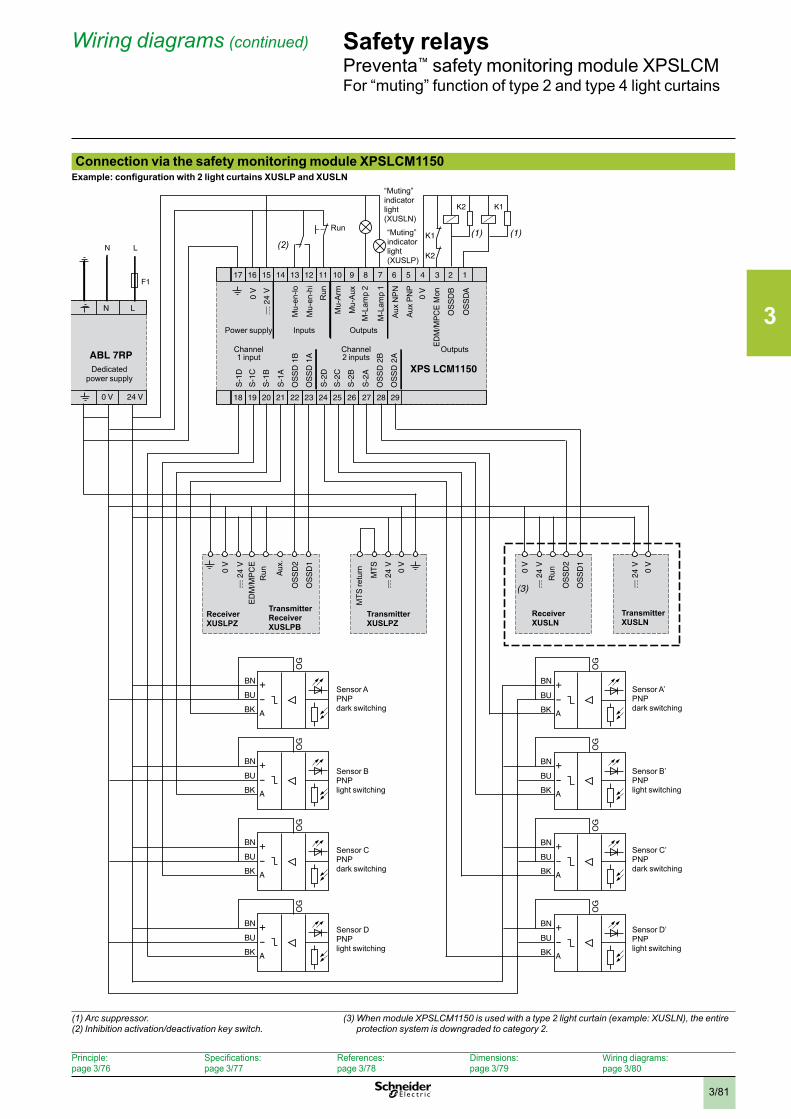
3
3/81
Safety relaysPreventa™ safety monitoring module XPSLCMFor “muting” function of type 2 and type 4 light curtains
Connection via the safety monitoring module XPSLCM1150Example: configuration with 2 light curtains XUSLP and XUSLN
(1) Arc suppressor .(2) Inhibition activation/deactivation key switch .
(3) When module XPSLCM1150 is used with a type 2 light curtain (example: XUSLN), the entire protection system is downgraded to category 2 .
Receiver XUSLPZ
Run
Dedicated power supply
“Muting” indicator light (XUSLP)
Mu-
en-lo
Mu-
en-h
i
Run
Mu-
Arm
Mu-
Aux
M-L
amp
2
M-L
amp
1
Aux
NP
N
Aux
PN
P
Power supply Inputs Outputs
Channel 1 input
Channel 2 inputs
Outputs
Run
Sensor A PNPdark switching
Sensor B PNPlight switching
Sensor C PNPdark switching
Sensor D PNPlight switching
Sensor A’PNPdark switching
Sensor B’ PNPlight switching
Sensor C’PNPdark switching
Sensor D’PNPlight switching
Transmitter Receiver XUSLPB
Transmitter XUSLPZ
Receiver XUSLN
Transmitter XUSLN
MTS
retu
rn
Run
“Muting” indicator light (XUSLN)
Wiring diagrams (continued)
(2)
Principle: page 3/76
Specifications: page 3/77
References: page 3/78
Dimensions: page 3/79
Wiring diagrams:page 3/80
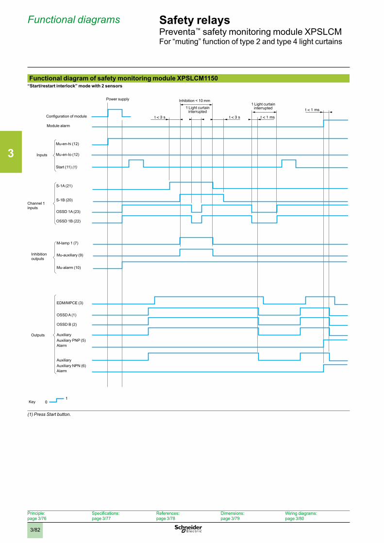
3
3/82
Safety relaysPreventa™ safety monitoring module XPSLCMFor “muting” function of type 2 and type 4 light curtains
Functional diagram of safety monitoring module XPSLCM1150“Start/restart interlock” mode with 2 sensors
(1) Press Start button .
Functional diagrams
t < 3 s t < 3 s t < 1 ms
t < 1 ms
01
Key
Inhibition < 10 mm
1 Light curtain interrupted
Configuration of module
Module alarm
Power supply
Mu-en-hi (12)
Inputs
S-1A (21)
Inhibition outputs
1 Light curtaininterrupted
Mu-en-Io (12)
Start (11) (1)
S-1B (20)
OSSD 1A (23)
OSSD 1B (22)
Channel 1 inputs
M-lamp 1 (7)
Mu-auxiliary (9)
Mu-alarm (10)
Outputs
EDM/MPCE (3)
OSSD A (1)
OSSD B (2)
Auxiliary PNP (5)Auxiliary
Alarm
Auxiliary NPN (6)Auxiliary
Alarm
Principle: page 3/76
Specifications: page 3/77
References: page 3/78
Dimensions: page 3/79
Wiring diagrams:page 3/80
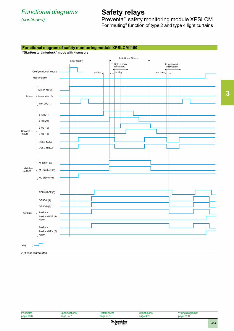
3
3/83
Safety relaysPreventa™ safety monitoring module XPSLCMFor “muting” function of type 2 and type 4 light curtains
Functional diagram of safety monitoring module XPSLCM1150“Start/restart interlock” mode with 4 sensors
(1) Press Start button .
Functional diagrams (continued)
t < 3 st < 3 s t < 1 ms
01
Key
Inhibition < 10 mm
1 Light curtain interrupted
Configuration of module
Module alarm
Power supply
Mu-en-hi (12)
Inputs
S-1A (21)
Inhibition outputs
1 Light curtaininterrupted
Mu-en-Io (12)
Start (11) (1)
S-1B (20)
OSSD 1A (23)
OSSD 1B (22)
Channel 1 inputs
M-lamp 1 (7)
Mu-auxiliary (9)
Mu-alarm (10)
Outputs
EDM/MPCE (3)
OSSD A (1)
OSSD B (2)
Auxiliary PNP (5)
Auxiliary
Alarm
Auxiliary NPN (6)
Auxiliary
Alarm
S-1C (19)
S-1D (18)
Principle: page 3/76
Specifications: page 3/77
References: page 3/78
Dimensions: page 3/79
Wiring diagrams:page 3/80
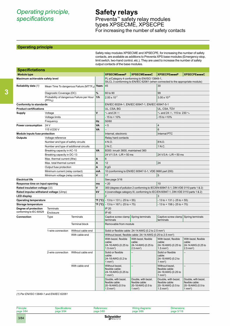
3
3/84
Operating principle, specifications
Principle:page 3/84
Specifications:page 3/84
References:page 3/85
Wiring diagrams:page 3/86
Dimensions:page 3/116
Safety relaysPreventa™ safety relay modules types XPSECME, XPSECPEFor increasing the number of safety contacts
Operating principleSafety relay modules XPSECME and XPSECPE, for increasing the number of safety contacts, are available as additions to Preventa XPS base modules (Emergency stop, limit switch, two-hand control, etc.). They are used to increase the number of safety output contacts of the base modules.
SpecifictationsModule type XPSECMEppppP XPSECMEppppC XPSECPEppppP XPSECPEppppC
Maximum achievable safety level PL e/Category 4 conforming to EN/ISO 13849-1, SILCL 3 conforming to EN/IEC 62061 (when connected to the appropriate module)
Reliability data (1) Mean Time To dangerous Failure (MTTFd) Years 45 30
Diagnostic Coverage (DC) % 60 to 90 99Probability of dangerous Failure per Hour (PFHd)
1/h 2.00 x 10⁻⁷ 3.00 x 10⁻⁹
Conformity to standards EN/IEC 60204-1, EN/IEC 60947-1, EN/IEC 60947-5-1Product certifications UL, CSA, BG UL, CSA, TÜVSupply Voltage V a and 24 c a and 24 c, 115 to 230 a
Voltage limits - 15 to + 10% -15 to +10%Frequency Hz 50/60
Power consumption 24 V VA < 5 4115 V/230 V VA – 6
Module inputs fuse protection Internal, electronic Internal PTCOutputs Voltage reference Relay hard contacts
Number and type of safety circuits 4 N.O. 8 N.O.Number and type of additional circuits 2 N.C. 1 N.C.Breaking capacity in AC-15 VA B300: inrush 3600, maintained 360Breaking capacity in DC-13 24 V/1.5 A - L/R = 50 ms 24 V/3 A - L/R = 50 msMax. thermal current (Ithe) A 6Max. total thermal current A 12 24Output fuse protection A 6 gGMinimum current (relay contact) mA 10 (conforming to EN/IEC 60947-5-1, VDE 0660 part 200)Minimum voltage (relay contact) V 17 5
Electrical life See page 3/16Response time on input opening ms < 20 10Rated insulation voltage (Ui) V 300 (degree of pollution 2 conforming to IEC/EN 60947-5-1, DIN VDE 0110 parts 1 & 2)Rated impulse withstand voltage (Uimp) kV 4 (overvoltage category III, conforming to IEC/EN 60947-1, DIN VDE 0110 parts 1 & 2)LED display 2 3Operating temperature °F (°C) - 13 to + 131 (- 25 to + 55) - 13 to + 131 (- 25 to + 55)Storage temperature °F (°C) - 13 to + 167 (- 25 to + 75) - 13 to + 158 (- 25 to + 70)Degree of protection conforming to IEC 60529
Terminals IP 20Enclosure IP 40
Connection Type Terminals Captive screw clamp terminals
Spring terminals Captive screw clamp terminals
Spring terminals
Terminal block Removable from module
1-wire connection Without cable end Solid or flexible cable: 24-14 AWG (0.2 to 2.5 mm2)With cable end Without bezel, flexible cable: 24-14 AWG (0.25 to 2.5 mm2)
With bezel, flexible cable: 24-16 AWG (0.25 to 1.5 mm2)
With bezel, flexible cable: 24-14 AWG (0.25 to 2.5 mm2)
With bezel, flexible cable: 24-16 AWG (0.25 to 1.5 mm2)
With bezel, flexible cable: 24-14 AWG (0.25 to 2.5 mm2)
2-wire connection Without cable end Solid or flexible cable: 24-18 AWG (0.2 to 1 mm2)
– Solid or flexible cable: 24-18 AWG (0.2 to 1 mm2)
–
With cable end Without bezel, flexible cable: 24-18 AWG (0.25 to 1 mm2)
– Without bezel, flexible cable: 24-18 AWG (0.25 to 1 mm2)
–
Double, with bezel, flexible cable: 20-16 AWG (0.5 to 1.5 mm2)
Double, with bezel, flexible cable: 20-18 AWG (0.5 to 1 mm2)
Double, with bezel, flexible cable: 20-16 AWG (0.5 to 1.5 mm2)
Double, with bezel, flexible cable: 20-18 AWG (0.5 to 1 mm2)
(1) Per EN/ISO 13849-1 and EN/IEC 62061
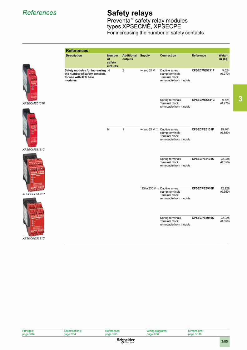
3
3/85
References
Principle:page 3/84
Specifications:page 3/84
References:page 3/85
Wiring diagrams:page 3/86
Dimensions:page 3/116
ReferencesDescription Number
of safety circuits
Additional outputs
Supply Connection Reference Weight oz (kg)
Safety modules for increasing the number of safety contacts, for use with XPS base modules
4 2 a and 24 V c Captive screw clamp terminalsTerminal block removable from module
XPSECME5131P 9.524(0.270)
Spring terminals Terminal block removable from module
XPSECME5131C 9.524(0.270)
8 1 a and 24 V c Captive screw clamp terminalsTerminal block removable from module
XPSECPE5131P 19.401(0.550)
Spring terminals Terminal block removable from module
XPSECPE5131C 22.928(0.650)
115 to 230 V a Captive screw clamp terminalsTerminal block removable from module
XPSECPE3910P 22.928(0.650)
Spring terminals Terminal block removable from module
XPSECPE3910C 22.928(0.650)
Safety relaysPreventa™ safety relay modules types XPSECME, XPSECPEFor increasing the number of safety contacts
XPSECME5131P
XPSECPE5131C
XPSECPE5131P
XPSECME5131C
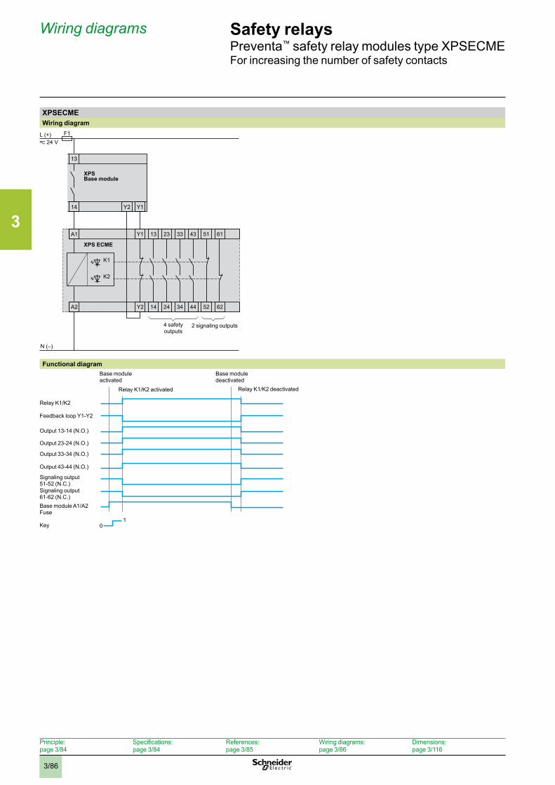
3
3/86
Wiring diagrams
Principle:page 3/84
Specifications:page 3/84
References:page 3/85
Wiring diagrams:page 3/86
Dimensions:page 3/116
Safety relaysPreventa™ safety relay modules type XPSECMEFor increasing the number of safety contacts
XPSECMEWiring diagram
A2
F1L (+)z 24 V
N (–)
A1 Y1 13
Y2 14
13
Y1Y214
K1
K2
23
24
33
34
43
44
51
52
61
62
XPS
XPS ECME
Base module
4 safety outputs
2 signaling outputs
Functional diagram
01
Relay K1/K2 deactivated
Base module deactivated
Relay K1/K2
Key
Feedback loop Y1-Y2
Signaling output51-52 (N.C.)
Output 13-14 (N.O.)
Relay K1/K2 activated
Base module activated
Output 23-24 (N.O.)
Output 33-34 (N.O.)
Output 43-44 (N.O.)
Signaling output61-62 (N.C.)Base module A1/A2Fuse
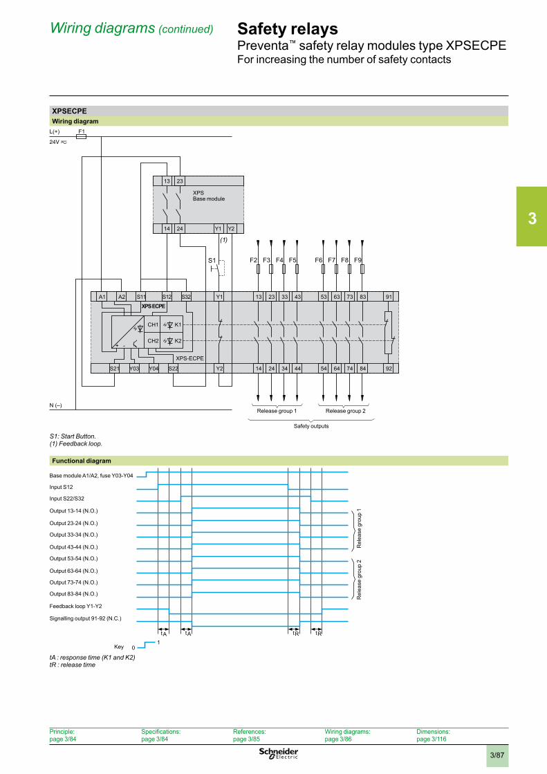
3
3/87
Wiring diagrams (continued)
Principle:page 3/84
Specifications:page 3/84
References:page 3/85
Wiring diagrams:page 3/86
Dimensions:page 3/116
Safety relaysPreventa™ safety relay modules type XPSECPEFor increasing the number of safety contacts
XPSECPEWiring diagram
F1
N (–)
XPS-ECPE
Y1 13
Y2 14
23S11 S12A1 S32
24
33
34Y03 Y04S21 S22
43
44
53
54
63
64
73
74
83
84
91
92
13 23
Y2Y114 24
XPS
K1
K2
CH1
CH2+ -
L(+)
A2
F2 F3 F4 F5 F6
(1)
F7 F8 F9
XPS ECPE
S1
Release group 1
Safety outputs
Release group 2
Base module
S1: Start Button . (1) Feedback loop .
Functional diagram
Key
tR tRtA tA
01
Input S12
Output 23-24 (N.O.)
Output 53-54 (N.O.)
Output 83-84 (N.O.)
Input S22/S32
Output 33-34 (N.O.)
Output 63-64 (N.O.)
Feedback loop Y1-Y2
Base module A1/A2, fuse Y03-Y04
Output 13-14 (N.O.)
Output 43-44 (N.O.)
Output 73-74 (N.O.)
Signalling output 91-92 (N.C.)
Rel
ease
gro
up 1
Rel
ease
gro
up 2
tA : response time (K1 and K2)tR : release time
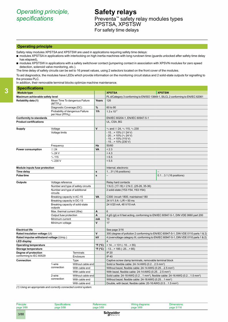
3
3/88
Safety relaysPreventa™ safety relay modules types XPSTSA, XPSTSWFor safety time delays
Operating principle, specifications
Operating principleSafety relay modules XPSTSA and XPSTSW are used in applications requiring safety time delays:
b modules XPSTSA in applications with interlocking on high inertia machines with long rundown time (guards unlocked after safety time delay has elapsed),
b modules XPSTSW in applications with a safety switchover contact (jumpering contact in association with XPSVN modules for zero speed detection, solenoid valve monitoring, etc.).
The time delay of safety circuits can be set to 16 preset values, using 2 selectors located on the front cover of the modules.To aid diagnostics, the modules have LEDs which provide information on the monitoring circuit status and 2 solid-state outputs for signalling to the process PLC.In addition, their removable terminal blocks optimize machine maintenance.
SpecificationsModule type XPSTSA XPSTSW
Maximum achievable safety level PL d/Category 3 conforming to EN/ISO 13849-1, SILCL 2 conforming to EN/IEC 62061 Reliability data (1) Mean Time To dangerous Failure
(MTTFd)Years 126
Diagnostic Coverage (DC) % 60 to 90Probability of dangerous Failure per Hour (PFHd)
1/h 1.3 x 10⁻⁷
Conformity to standards EN/IEC 60204-1, EN/IEC 60947-5-1Product certifications UL, CSA, BG
Supply Voltage V a and c 24, a 115, a 230Voltage limits - 15…+ 15% (c 24 V)
- 20…+ 10% (a 24 V)- 15…+ 15% (115 V)- 15…+ 10% (230 V)
Frequency Hz 50/60Power consumption c 24 VA < 2.3
a 24 V < 4.3a 115 < 6.5a 230 V < 5.5
Module inputs fuse protection Internal, electronicTime delay s 1…31 (16 positions) –Pulse time s – 0.1…3.1 (16 positions)
Outputs Voltage reference Relay hard contactsNumber and type of safety circuits 1 N.O. (17-18) + 2 N.C. (25-26, 35-36)Number and type of additional circuits
2 solid-state (Y53-Y54, Y63-Y64)
Breaking capacity in AC-15 VA C300: inrush 1800, maintained 180Breaking capacity in DC-13 24 V/1.5 A - L/R = 50 msBreaking capacity of solid-state outputs
24 V/20 mA, 48 V/10 mA
Max. thermal current (Ithe) A 6Output fuse protection A 4 gG (gl) or 6 fast acting, conforming to EN/IEC 60947-5-1, DIN VDE 0660 part 200Minimum current mA 10Minimum voltage V 17
Electrical life See page 3/16Rated insulation voltage (Ui) V 300 (degree of pollution 2 conforming to EN/IEC 60947-5-1, DIN VDE 0110 parts 1 & 2)Rated impulse withstand voltage (Uimp.) kV 4 (overvoltage category III, conforming to EN/IEC 60947-5-1, DIN VDE 0110 parts 1 & 2)LED display 4Operating temperature °F (°C) + 14…+ 131 (- 10…+ 55)Storage temperature °F (°C) - 13…+ 185 (- 25…+ 85)Degree of protection conforming to IEC 60529
Terminals IP 20Enclosure IP 40
Connection Type Captive screw clamp terminals, removable terminal block1-wire connection
Without cable end Solid or flexible cable: 24-14 AWG (0.2…2.5 mm2)With cable end Without bezel, flexible cable: 24-14 AWG (0.25…2.5 mm2)With cable end With bezel, flexible cable: 24-14 AWG (0.25…2.5 mm2)
2-wire connection
Without cable end Solid cable: 24-18 AWG (0.2…1 mm2), flexible cable: 24-16 AWG (0.2…1.5 mm2)With cable end Without bezel, flexible cable: 24-18 AWG (0.25…1 mm2)With cable end Double, with bezel, flexible cable: 20-16 AWG (0.5…1.5 mm2)
(1) Using an appropriate and correctly connected control system .
Principle:page 3/88
Specifications:page 3/88
References:page 3/89
Wiring diagrams:page 3/89
Dimensions:page 3/116
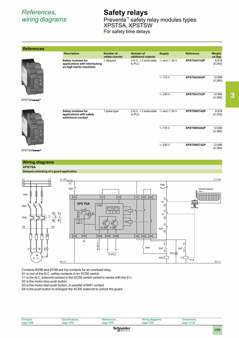
3
3/89
Safety relaysPreventa™ safety relay modules types XPSTSA, XPSTSWFor safety time delays
References, wiring diagrams
ReferencesDescription Number of
safety circuitsNumber of additional outputs
Supply Reference Weightoz (kg)
Safety modules for applications with interlocking on high inertia machines
1 delayed 2 N.C. + 2 solid-state to PLC
a and c 24 V
XPSTSA5142P 8.818 (0.250)
a 115 V
XPSTSA3442P 12.699 (0.360)
a 230 V
XPSTSA3742P 12.699 (0.360)
Safety modules for applications with safety switchover contact
1 pulse type 2 N.C. + 2 solid-state to PLC
a and c 24 V
XPSTSW5142P 8.818 (0.250)
a 115 V
XPSTSW3442P 12.699 (0.360)
a 230 V
XPSTSW3742P 12.699 (0.360)
Wiring diagramsXPSTSADelayed unlocking of a guard application
A1 25 35Y2 17
A2 18PE Y53 Y54 Y64 26 36
Y1
F1
L1 (+) L1 (+)
+
N ( ) N ( )
K1/K2 F OK
K2
K1
S3
1413
KM1
T
KM1
KM1
XPS TSA
1 2
S4
1413
Y1
S2
2221
S1
2221
Y1
5251
FM2
KM1
L1 L1
FM2
PE PE
PEV WU
FM1
U W PEV
M 3
9897
9695
L2 L2L3 L3
H1To PLC
Guard closed
Logic
Contacts 95/96 and 97/98 are trip contacts for an overload relay.S1 is one of the N.C. safety contacts in an XCSE switchY1 is the N.C. solenoid contact in the XCSE switch (wired in series with the S1)S2 is the motor stop push buttonS3 is the motor start push button, in parallel of KM1 contactS4 is the push button to energize the XCSE solenoid to unlock the guard
XPSTSAppppP
XPSTSWppppP
Principle:page 3/88
Specifications:page 3/88
References:page 3/89
Wiring diagrams:page 3/89
Dimensions:page 3/116
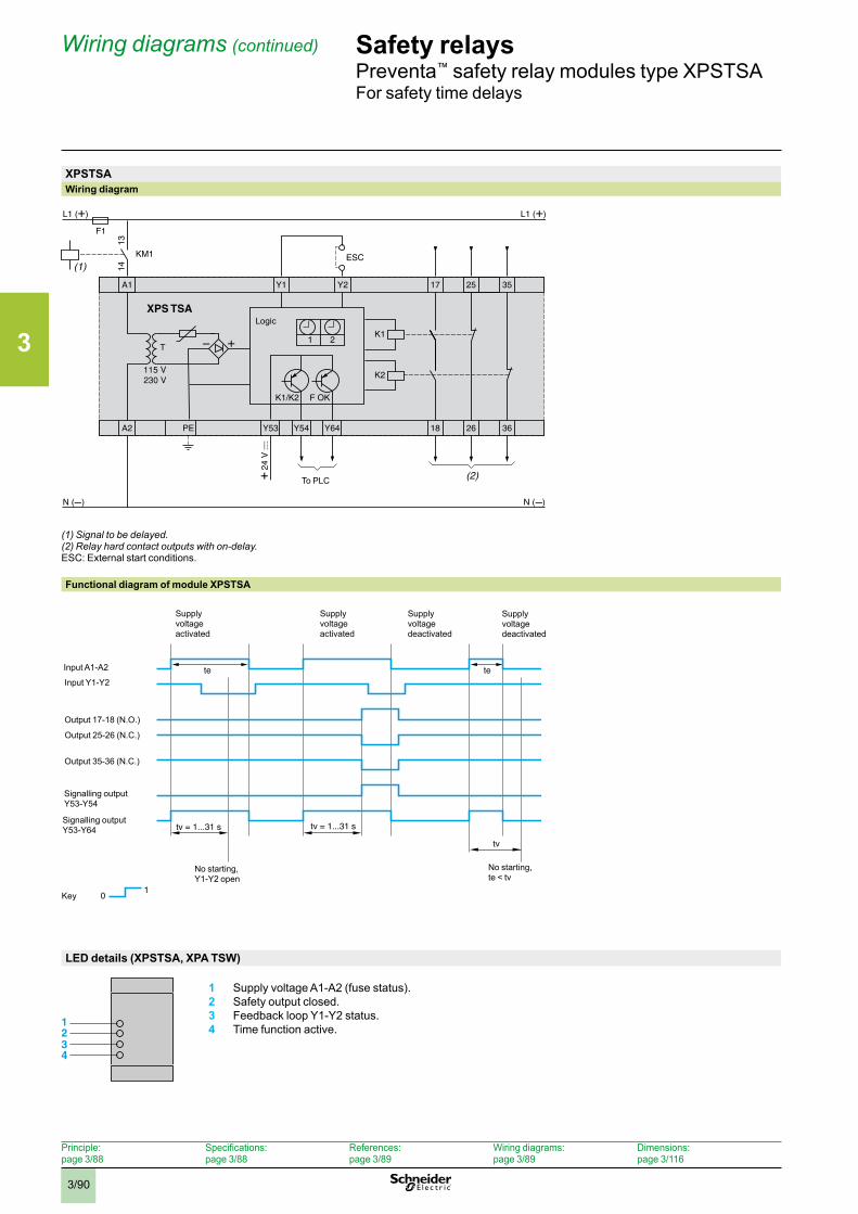
3
3/90
Safety relaysPreventa™ safety relay modules type XPSTSAFor safety time delays
Wiring diagrams (continued)
XPSTSAWiring diagram
(1) Signal to be delayed .(2) Relay hard contact outputs with on-delay .ESC: External start conditions.
Functional diagram of module XPSTSA
LED details (XPSTSA, XPA TSW)
1 Supply voltage A1-A2 (fuse status).2 Safety output closed.3 Feedback loop Y1-Y2 status.4 Time function active.
To PLC
Logic
10
tv = 1...31 s tv = 1...31 s
tete
tv
Key
Supply voltage activated
Input A1-A2
Input Y1-Y2
Output 17-18 (N.O.)
Signalling output Y53-Y54
Supply voltage activated
Supply voltage deactivated
Supply voltage deactivated
Output 25-26 (N.C.)
Output 35-36 (N.C.)
Signalling output Y53-Y64
No starting, Y1-Y2 open
No starting, te < tv
1234
Principle:page 3/88
Specifications:page 3/88
References:page 3/89
Wiring diagrams:page 3/89
Dimensions:page 3/116
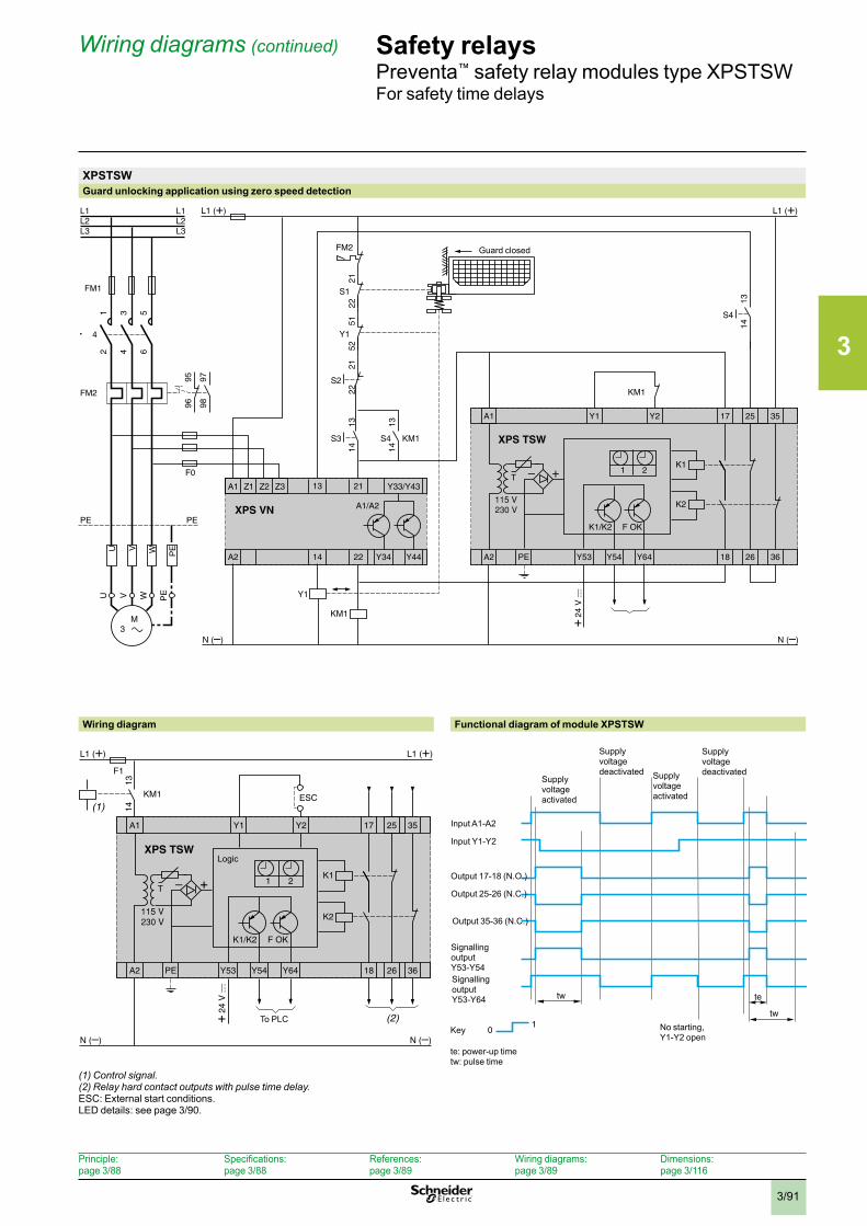
3
3/91
Safety relaysPreventa™ safety relay modules type XPSTSWFor safety time delays
Wiring diagrams (continued)
XPSTSWGuard unlocking application using zero speed detection
Wiring diagram Functional diagram of module XPSTSW
te: power-up timetw: pulse time
(1) Control signal .(2) Relay hard contact outputs with pulse time delay .ESC: External start conditions. LED details: see page 3/90.
A1 25 35Y2 17
A2 18PE Y53 Y54 Y64 26 36
Y1
L1 (+) L1 (+)
+
K1/K2 F OK
K2
K1
S3 KM1
1413
T
KM1
XPS TSW
1 2
A1 Z1 Z2 Z3 Y33/Y43
A2 22 Y34
21
14
13
Y44
A1/A2
F0
XPS VN
S4
1413
Y1
KM1
S2
2221
S1
2221
Y1
5251
FM2
4
L1 L1
FM2
PE PE
PEV WU
FM1
U W PEV
2 64
1 53
M 3
9897
9695
L2 L2L3 L3
S4
1413
Guard closed
14
13
ESC
A1 25 35Y2 17
A2 18PE Y53 Y54 Y64 26 36
Y1
F1
L1 (+) L1 (+)
K1/K2 F OK
K2
K1
T
KM1
XPS TSW
1 2
(1)
(2)To PLC
Logic
tw te
10
tw
Key
Supply voltage deactivated
Supply voltage activated
Input A1-A2
Input Y1-Y2
Output 17-18 (N.O.)
Signalling output Y53-Y64
Supply voltage activated
Supply voltage deactivated
Output 25-26 (N.C.)
Output 35-36 (N.C.)
No starting, Y1-Y2 open
Signalling output Y53-Y54
Principle:page 3/88
Specifications:page 3/88
References:page 3/89
Wiring diagrams:page 3/89
Dimensions:page 3/116
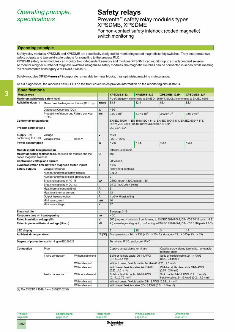
3
3/92
Safety relays Preventa™ safety relay modules types XPSDMB, XPSDMEFor non-contact safety interlock (coded magnetic) switch monitoring
Operating principle, specifications
Operating principleSafety relay modules XPSDMB and XPSDME are specifically designed for monitoring coded magnetic safety switches. They incorporate two safety outputs and two solid-state outputs for signalling to the process PLC. XPSDMB safety relay modules can monitor two independent sensors and modules XPSDME can monitor up to six independent sensors. To monitor a higher number of magnetic switches using these safety modules, the magnetic switches can be connected in series, while meeting the requirements of category 3 of EN/ISO 13849-1.
Safety modules XPSDMpppppP incorporate removable terminal blocks, thus optimizing machine maintenance.
To aid diagnostics, the modules have LEDs on the front cover which provide information on the monitoring circuit status.
SpecificationsModule type XPSDMB1132 XPSDME1132 XPSDMB1132P XPSDME1132P
Maximum achievable safety level PL e/Category 4 conforming to EN/ISO 13849-1, SILCL 3 conforming to EN/IEC 62061 Reliability data (1) Mean Time To dangerous Failure (MTTFd) Years 83.1 82.4 83.1 82.4
Diagnostic Coverage (DC) % > 99Probability of dangerous Failure per Hour (PFHd)
1/h 3.92 x 10⁻⁹ 3.97 x 10⁻⁹ 3.92 x 10⁻⁹ 3.97 x 10⁻⁹
Conformity to standards EN/IEC 60204-1, EN 1088/ISO 14119, EN/IEC 60947-5-1, EN/IEC 60947-5-3, DIN V VDE 0801 (1990), DIN V VDE 0801 A1 (1994)
Product certifications UL, CSA, BIA
Supply (Ue) conforming to IEC 38
Voltage V c 24Voltage limits c 24 V - 20…+ 20%
Power consumption W < 2.5 < 3.5 < 2.5 < 3.5
Module inputs fuse protection Internal, electronicMaximum wiring resistance RL between the module and the coded magnetic switches
W 100
Control unit voltage and current 28 V/8 mASynchronization time between magnetic switch inputs s < 0.5 Safety outputs Voltage reference Relay hard contacts
Number and type of safety circuits 2 N.O.Number and type of solid-state outputs 2Breaking capacity in AC-15 VA C300: inrush 1800, sealed: 180Breaking capacity in DC-13 24 V/1.5 A, L/R = 50 msMax. thermal current (Ithe) A 6Max. total thermal current A 12Output fuse protection A 4 gG or 6 fast actingMinimum current mA 10Minimum voltage V 17
Electrical life See page 3/16Response time on input opening ms < 20Rated insulation voltage (Ui) V 300 (degree of pollution 2 conforming to EN/IEC 60947-5-1, DIN VDE 0110 parts 1 & 2)Rated impulse withstand voltage (Uimp.) kV 4 (overvoltage category III, conforming to EN/IEC 60947-5-1, DIN VDE 0110 parts 1 & 2)
LED display 3 15 3 15Ambient air temperature °F (°C) For operation: + 14…+ 131 (- 10…+ 55), for storage: - 13…+ 185 (- 25…+ 85)
Degree of protection conforming to IEC 60529 Terminals: IP 20, enclosure: IP 40
Connection Type Captive screw clamp terminals Captive screw clamp terminals, removable terminal block
1-wire connection Without cable end Solid or flexible cable: 26-14 AWG (0.14… 2.5 mm2)
Solid or flexible cable: 24-14 AWG (0.2…2.5 mm2)
With cable end Without bezel, flexible cable: 24-14 AWG (0.25…2.5 mm2)With cable end With bezel, flexible cable: 24-16 AWG
(0.25…1.5 mm2)With bezel, flexible cable: 24-14 AWG (0.25…2.5 mm2)
2-wire connection Without cable end Solid or flexible cable: 26-18 AWG(0.14…0.75 mm2)
Solid cable: 24-18 AWG (0.2…1 mm2), flexible cable: 24-16 AWG (0.2…1.5 mm2)
With cable end Without bezel, flexible cable: 24-18 AWG (0.25…1 mm2)With cable end With bezel, flexible cable: 20-16 AWG (0.5… 1.5 mm2)
(1) Per EN/ISO 13849-1 and EN/IEC 62061
Principle:page 3/92
Specifications:page 3/92
References:page 3/93
Wiring diagrams:page 3/94
Dimensions:page 3/116
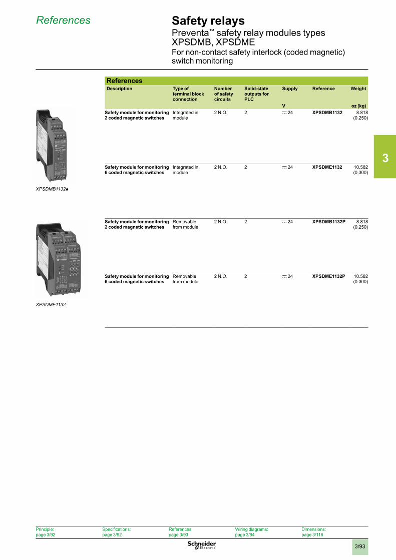
3
3/93
Safety relays Preventa™ safety relay modules types XPSDMB, XPSDMEFor non-contact safety interlock (coded magnetic) switch monitoring
XPSDMB1132p
ReferencesDescription Type of
terminal block connection
Number of safety circuits
Solid-state outputs for PLC
Supply Reference Weight
V oz (kg)Safety module for monitoring 2 coded magnetic switches
Integrated in module
2 N.O. 2 c 24
XPSDMB1132 8.818 (0.250)
Safety module for monitoring 6 coded magnetic switches
Integrated in module
2 N.O. 2 c 24
XPSDME1132 10.582 (0.300)
Safety module for monitoring 2 coded magnetic switches
Removable from module
2 N.O. 2 c 24
XPSDMB1132P 8.818 (0.250)
Safety module for monitoring 6 coded magnetic switches
Removable from module
2 N.O. 2 c 24 XPSDME1132P 10.582 (0.300)
XPSDME1132
References
Principle:page 3/92
Specifications:page 3/92
References:page 3/93
Wiring diagrams:page 3/94
Dimensions:page 3/116
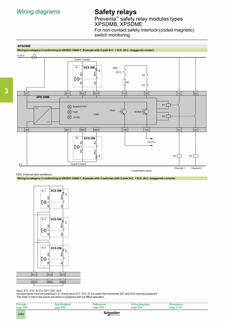
3
3/94
XPSDMBWiring to category 4 conforming to EN/ISO 13849-1. Example with 2-pole N.C. + N.O. (N.C. staggered) contact.
ESC: External start conditions.Wiring to category 3 conforming to EN/ISO 13849-1. Example with 3 switches with 2-pole N.C. + N.O. (N.C. staggered) contacts.
Input: S11, S12, S13 or S21, S22, S23 . Unused inputs must be jumpered: i .e .: if only input S11, S12, S13 is used, then terminals S21 and S23 must be jumpered .The order in which the inputs are wired or jumpered will not affect operation .
A1 Y1 Y2 13S11 S12 S13
S1 XCS DM
K4
K3
K1
K3
K2
K1/K2
BK
WH
K4
BU
BN+
A2 Y34 Y44 14
23
24S21 S22 S23
K1/K2
S2 XCS DM
XPS DMB
WH
BK
BN+
BU
S3
ESC
F1+ 24 V
0 V
Start
Logic
Supply A1/A2
Fault Fault
Channel 1 Channel 2
To PLC
2 solid-state outputs
Guard 2 closed
Guard 1 closed
Safety relays Preventa™ safety relay modules types XPSDMB, XPSDMEFor non-contact safety interlock (coded magnetic) switch monitoring
S11 S12 S13
S1.3 XCS DM
BK
WH
BU
BN+
S1.2 XCS DM
BK
WH
BU
BN+
S1.1 XCS DM
BK
WH
BU
BN+
S21 S22 S23
Wiring diagrams
Principle:page 3/92
Specifications:page 3/92
References:page 3/93
Wiring diagrams:page 3/94
Dimensions:page 3/116
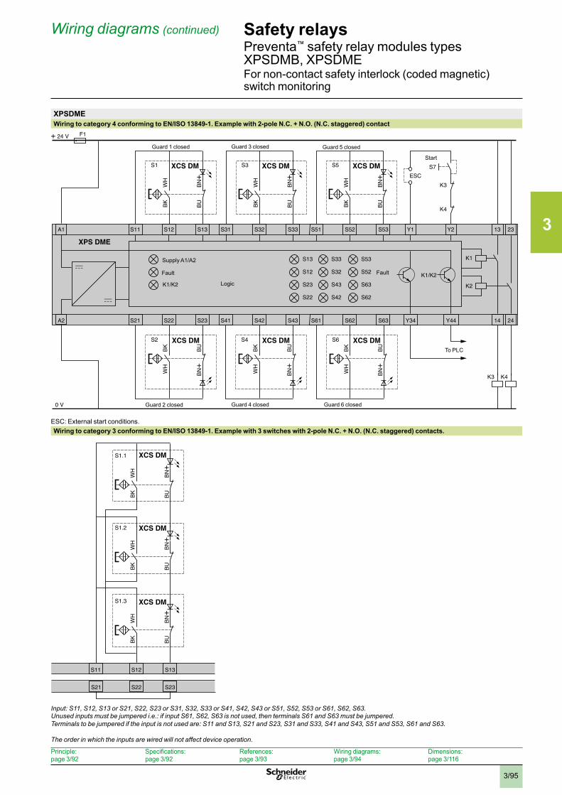
3
3/95
Safety relays Preventa™ safety relay modules types XPSDMB, XPSDMEFor non-contact safety interlock (coded magnetic) switch monitoring
S11 S12 S13
S1.3 XCS DM
BK
WH
BU
BN+
S1.2 XCS DM
BK
WH
BU
BN+
S1.1 XCS DM
BK
WH
BU
BN+
S21 S22 S23
Wiring diagrams (continued)
XPSDMEWiring to category 4 conforming to EN/ISO 13849-1. Example with 2-pole N.C. + N.O. (N.C. staggered) contact
ESC: External start conditions.Wiring to category 3 conforming to EN/ISO 13849-1. Example with 3 switches with 2-pole N.C. + N.O. (N.C. staggered) contacts.
Input: S11, S12, S13 or S21, S22, S23 or S31, S32, S33 or S41, S42, S43 or S51, S52, S53 or S61, S62, S63 . Unused inputs must be jumpered i .e .: if input S61, S62, S63 is not used, then terminals S61 and S63 must be jumpered .Terminals to be jumpered if the input is not used are: S11 and S13, S21 and S23, S31 and S33, S41 and S43, S51 and S53, S61 and S63 .
The order in which the inputs are wired will not affect device operation .
A1 Y1 Y2 13S11 S12 S13
S1 XCS DM XCS DM XCS DM
K4
K3
K1
K3
K2
K1/K2
BK
WH
BU
BN+
S31 S32 S33
S3
BK
WH
BU
BN+
S51 S52 S53
A2 Y34 Y44 14
23
K4
24S21 S22 S23 S41 S42 S43 S61 S62 S63
S13
S12
S23
S22
K1/K2
S53
S52
S63
S62
S33
S32
S43
S42
S5
BK
WH
BU
BN+
S2 XCS DM
XPS DME
WH
BK
BN+
BU
S4 XCS DM
WH
BK
BN+
BU
S6 XCS DMW
HB
K
BN+
BU
S7
ESC
F1+ 24 V
0 V
Start
Logic
Supply A1/A2
Fault Fault
To PLC
Guard 2 closed
Guard 1 closed
Guard 4 closed Guard 6 closed
Guard 3 closed Guard 5 closed
Principle:page 3/92
Specifications:page 3/92
References:page 3/93
Wiring diagrams:page 3/94
Dimensions:page 3/116
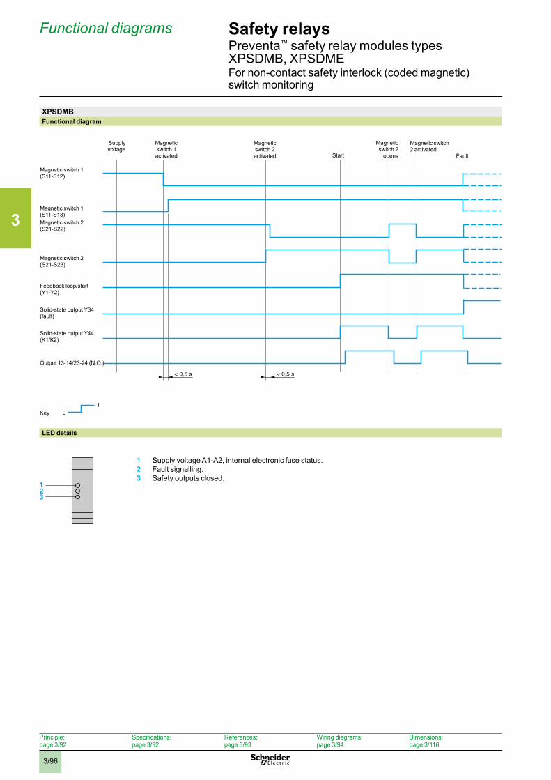
3
3/96
Safety relays Preventa™ safety relay modules types XPSDMB, XPSDMEFor non-contact safety interlock (coded magnetic) switch monitoring
Functional diagrams
XPSDMBFunctional diagram
LED details
1 Supply voltage A1-A2, internal electronic fuse status.2 Fault signalling.3 Safety outputs closed.
123
1 0
< 0,5 s < 0,5 s
Magnetic switch 1 activated
Supplyvoltage
Key
Magnetic switch 1(S11-S12)
Output 13-14/23-24 (N.O.)
Magnetic switch 2 activated Start Fault
Magnetic switch 1(S11-S13)Magnetic switch 2(S21-S22)
Magnetic switch 2(S21-S23)
Solid-state output Y44 (K1/K2)
Solid-state output Y34 (fault)
Feedback loop/start (Y1-Y2)
Magnetic switch 2
opens
Magnetic switch 2 activated
Principle:page 3/92
Specifications:page 3/92
References:page 3/93
Wiring diagrams:page 3/94
Dimensions:page 3/116
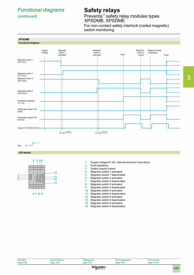
3
3/97
Safety relays Preventa™ safety relay modules types XPSDMB, XPSDMEFor non-contact safety interlock (coded magnetic) switch monitoring
Functional diagrams (continued)
XPSDMEFunctional diagram
LED details
1 Supply voltage A1-A2, internal electronic fuse status.2 Fault signalling.3 Safety outputs closed.4 Magnetic switch 1 activated.5 Magnetic switch 1 deactivated.6 Magnetic switch 2 activated.7 Magnetic switch 2 deactivated.8 Magnetic switch 3 activated.9 Magnetic switch 3 deactivated.10 Magnetic switch 4 activated.11 Magnetic switch 4 deactivated.12 Magnetic switch 5 activated.13 Magnetic switch 5 deactivated.14 Magnetic switch 6 activated.15 Magnetic switch 6 deactivated.
12
45 8 9
76 10 11
12131415
3
1 0
< 0,5 s < 0,5 s
Magnetic switch 1 activated
Supplyvoltage
Key
Magnetic switch 1(S11-S12)
Output 13-14/23-24 (N.O.)
Magnetic switch 2 activated Start Fault
Magnetic switch 1(S11-S13)Magnetic switch 2(S21-S22)
Magnetic switch 2(S21-S23)
Solid-state output Y44 (K1/K2)
Solid-state output Y34 (fault)
Feedback loop/start (Y1-Y2)
Magnetic switch 2
opens
Magnetic switch 2 activated
Principle:page 3/92
Specifications:page 3/92
References:page 3/93
Wiring diagrams:page 3/94
Dimensions:page 3/116
3
3/98
Safety relaysPreventa™ safety relay modules type XPSVNEFor zero speed detection
Operating principlePreventa™ safety relay modules type XPSVNE for zero speed detection are used to detect the stop condition of electric motors. Their most common applications include: providing the unlock signal for electrically interlocked sliding or removable machine guards, controlling rotation direction signals for reversing motors and engaging locking brakes after a motor has come to a standstill.
As electric motors run down, a remanent voltage is produced in the windings of the motor due to residual magnetism. This voltage is proportional to the speed of the motor and, therefore, decreases as the motor comes to a standstill.This remanent voltage is measured in a redundant manner so as to detect the stop condition of the motor. The cabling between the motor windings and the inputs of the XPSVNE module is also monitored to prevent a cabling breakage or anomaly being seen as a stopped motor.A transformer should not be used to connect the motor to terminals Z1, Z2 and Z3 since there is no monitoring of the connection with the motor winding via the resistance monitoring.
Modules XPSVNE are suitable for detecting the stop condition of all types of a.c. or d.c. motor driven machines which, when the motor runs down, produce a remanent voltage in the windings due to residual magnetism. These machines can be controlled by electronic devices, such as variable speed drives or d.c. injection brakes.The input filters for standard XPSVNE modules are designed for a frequency of up to 60 Hz.For motors operating at a frequency higher than 60 Hz, which therefore produce a high frequency remanent voltage, special modules XPSVNEppppHS should be used.
The XPSVNE is not compatible with Wound Rotor Motors. These motors are typically used in high HP (1000+) low speed applications, where the additional windings (required for these types of motors) pay for themselves. If power is removed from stator, but rotor is left energized, then transformer coupling between the two could create a small voltage across the stator. This could make the XPSVNE think the motor is still turning, which means the safety outputs would never energize or change state. These motors do not have residual magnetism in the rotor that can act as a source of flux for generator effect, in which case the XPSVNE may think the motor is at zero speed, and could energize the safety outputs while the motor is still running. Wound Rotor motors are not in common use today, and very rare.
The XPSVNE is not designed for use with single phase motors.
The XPSVNE is not designed to detect locked rotor conditions. Here the motor still has voltage applied to it, but in essence has zero speed. Generally, a locked rotor condition is not a safe state for machinery nor the operators. The XPSVN will sense voltage applied to the windings, and will not indicate the motor’s “apparent” zero speed. The outputs of the XPSVN will not change state, the gates or guards will not be unlocked, and operators will not be allowed access to the unsafe area.
Modules XPSVNE have 2 potentiometers mounted on the front cover of the module which allow independent adjustment of the switching threshold for each input circuit. This allows adjustment for different types of motors and application requirements.
To aid diagnostics, modules XPSVNE have 4 LEDs and 2 solid-state outputs to provide information on the status of the zero speed detection circuit.
Operating principle
Principle:page 3/98
Specifications:page 3/99
References:page 3/99
Wiring diagrams:page 3/100
Dimensions:page 3/116
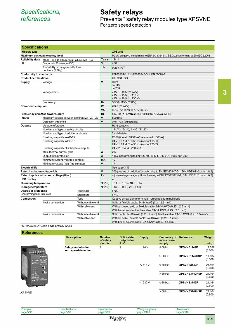
3
3/99
Safety relaysPreventa™ safety relay modules type XPSVNEFor zero speed detection
SpecificationsModule type XPSVNE
Maximum achievable safety level PL d/Category 3 conforming to EN/ISO 13849-1, SILCL 2 conforming to EN/IEC 62061 Reliability data (1)
Mean Time To dangerous Failure (MTTFd) Years 124.1Diagnostic Coverage (DC) % > 99Probability of dangerous Failure per Hour (PFHd)
1/h 9.26 x 10⁻⁹
Conformity to standards EN 60204-1, EN/IEC 60947-5-1, EN 50082-2Product certifications UL, CSA, BGSupply Voltage V c 24
a 115a 230
Voltage limits - 15…+ 10% (c 24 V)- 15…+ 15% (a 115 V)- 15…+ 10% (a 230 V)
Frequency Hz 50/60 (115 V, 230 V)Power consumption W y 3.5 (c 24 V)
VA y 7.5 (a115 V), y 7 (a 230 V)Frequency of motor power supply Hz y 60 Hz (XPSVNpp42), > 60 Hz (XPSVNpp42HS)Inputs Maximum voltage between terminals Z1 - Z2 - Z3 V 500 rms
Detection threshold V 0.01 - 0.1 (adjustable)Outputs Voltage reference Hard contacts
Number and type of safety circuits 1 N.O. (13-14), 1 N.C. (21-22)Number and type of additional circuits 2 solid-stateBreaking capacity in AC-15 C300 (inrush: 1800 VA/maintained: 180 VA)Breaking capacity in DC-13 24 V/1.5 A - L/R = 50 ms (contact 13-14)
24 V/1.2 A - L/R = 50 ms (contact 21-22)Breaking capacity of solid-state outputs 24 V/20 mA, 48 V/10 mAMax. thermal current (Ithe) A 2.5Output fuse protection A 4 gG, conforming to EN/IEC 60947-5-1, DIN VDE 0660 part 200Minimum current (volt-free contact) mA 10Minimum voltage (volt-free contact) V 17
Electrical life See page 3/16Rated insulation voltage (Ui) V 300 (degree of pollution 2 conforming to EN/IEC 60947-5-1, DIN VDE 0110 parts 1 & 2)Rated impulse withstand voltage (Uimp) kV 4 (overvoltage category III, conforming to EN//IEC 60947-5-1, DIN VDE 0110 parts 1 & 2)LED display 4Operating temperature °F (°C) + 14…+ 131 (- 10…+ 55)Storage temperature °F (°C) - 13…+ 185 (- 25…+ 85)Degree of protectionConforming to IEC 60529
Terminals IP 20Enclosure IP 40
Connection Type Captive screw clamp terminals, removable terminal block1-wire connection Without cable end Solid or flexible cable: 24-14 AWG (0.2…2.5 mm2)
With cable end Without bezel, solid or flexible cable: 24-14 AWG (0.25…2.5 mm2)With bezel, solid or flexible cable: 24-14 AWG (0.25…2.5 mm2)
2-wire connection Without cable end Solid cable: 24-18 AWG (0.2…1 mm2), flexible cable: 24-16 AWG (0.2…1.5 mm2)With cable end Without bezel, flexible cable: 24-18 AWG (0.25…1 mm2)
With bezel, flexible cable: 22-14 AWG (0.5…1.5 mm2)(1) Per EN/ISO 13849-1 and EN/IEC 62061
ReferencesDescription Number
of safety circuits
Solid-state outputs for PLC
Supply Frequency of motor power supply
Reference Weight
oz (kg)Safety modules for zero speed detection
2 2 c 24 V y 60 Hz
XPSVNE1142P 17.637 (0.500)
> 60 Hz
XPSVNE1142HSP 17.637 (0.500)
a 115 V y 60 Hz
XPSVNE3442P 21.164 (0.600)
> 60 Hz
XPSVNE3442HSP 21.164 (0.600)
a 230 V y 60 Hz
XPSVNE3742P 21.164 (0.600)
> 60 Hz
XPSVNE3742HSP 21.164 (0.600)
XPSVNE
Specifications, references
Principle:page 3/98
Specifications:page 3/99
References:page 3/99
Wiring diagrams:page 3/100
Dimensions:page 3/116
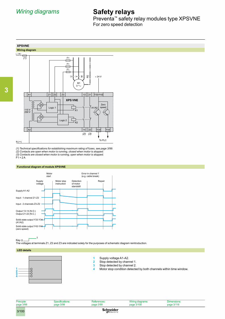
3
3/100
Safety relaysPreventa™ safety relay modules type XPSVNEFor zero speed detection
XPSVNEWiring diagram
Logic 1
Logic 2
To PLC
Zero speed
(1) Technical specifications for establishing maximum rating of fuses, see page 3/99 .(2) Contacts are open when motor is running, closed when motor is stopped .(3) Contacts are closed when motor is running, open when motor is stopped .F1 = 2 A
Functional diagram of module XPSVNE
Key 01
The voltages at terminals Z1, Z2 and Z3 are indicated solely for the purposes of schematic diagram reintroduction.
LED details
1 Supply voltage A1-A2.2 Stop detected by channel 1.3 Stop detected by channel 2.4 Motor stop condition detected by both channels within time window.
Supplyvoltage
Motor stop instruction
Motor start
Error in channel 1 (e.g. cable break)
Detection of motor standstill
Repair
Supply A1-A2
Input - 1 channel Z1-Z2
Output 13-14 (N.O.)Output 21-22 (N.C.)
Solid-state output Y33-Y34(A1/A2)
Solid-state output Y43-Y44(zero speed)
Input - 2 channels Z3-Z2
1234
Wiring diagrams
Principle:page 3/98
Specifications:page 3/99
References:page 3/99
Wiring diagrams:page 3/100
Dimensions:page 3/116
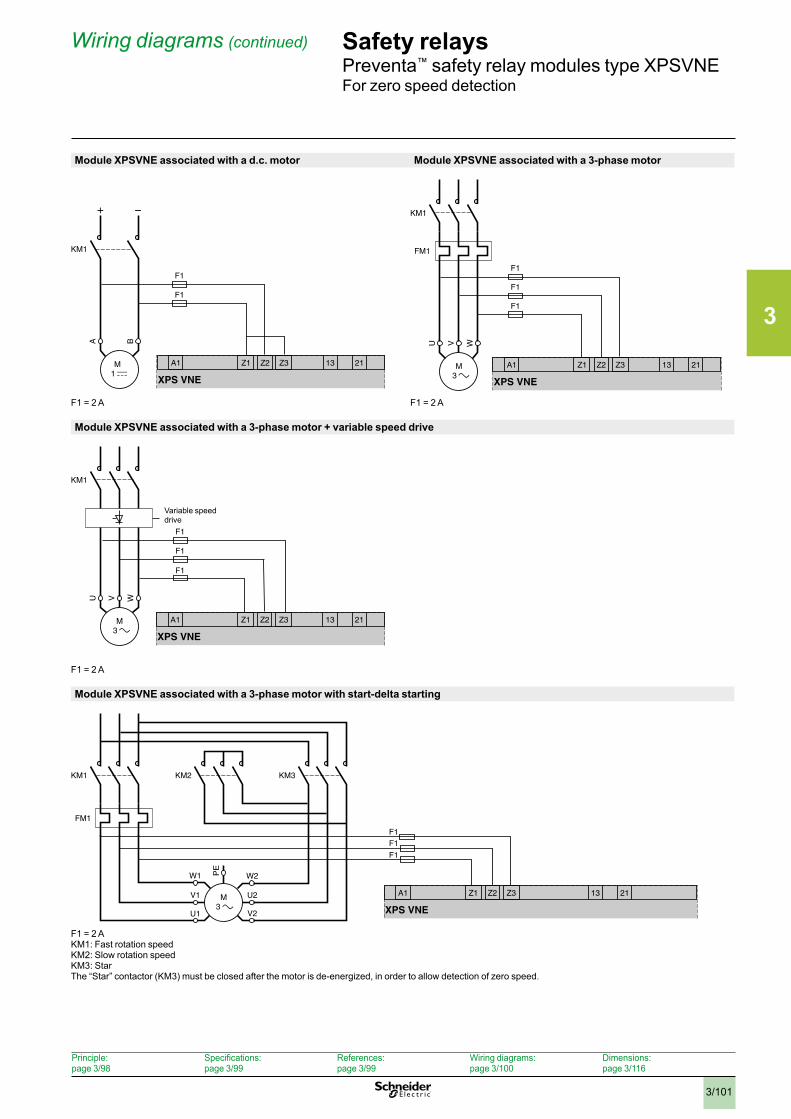
3
3/101
Safety relaysPreventa™ safety relay modules type XPSVNEFor zero speed detection
Module XPSVNE associated with a d.c. motor Module XPSVNE associated with a 3-phase motor
F1 = 2 A F1 = 2 A
Module XPSVNE associated with a 3-phase motor + variable speed drive
F1 = 2 A
Module XPSVNE associated with a 3-phase motor with start-delta starting
F1 = 2 AKM1: Fast rotation speedKM2: Slow rotation speedKM3: StarThe “Star” contactor (KM3) must be closed after the motor is de-energized, in order to allow detection of zero speed.
Z3Z1A1 Z2 21
XPS VNE
13
F1
F1
KM1
A B
M 1
+ –
Z3Z1A1 Z2 21
XPS VNE
13
F1
F1
F1
FM1
KM1
U WV
M 3
Z3Z1A1 Z2 21
XPS VNE
13
KM1
U WV
M 3
F1
F1
F1
Variable speeddrive
Z3Z1A1 Z2 21
XPS VNE
13
PE
F1
F1
M3
W1
U1
V1
W2
V2
U2
KM2
FM1
KM1 KM3
F1
Wiring diagrams (continued)
Principle:page 3/98
Specifications:page 3/99
References:page 3/99
Wiring diagrams:page 3/100
Dimensions:page 3/116
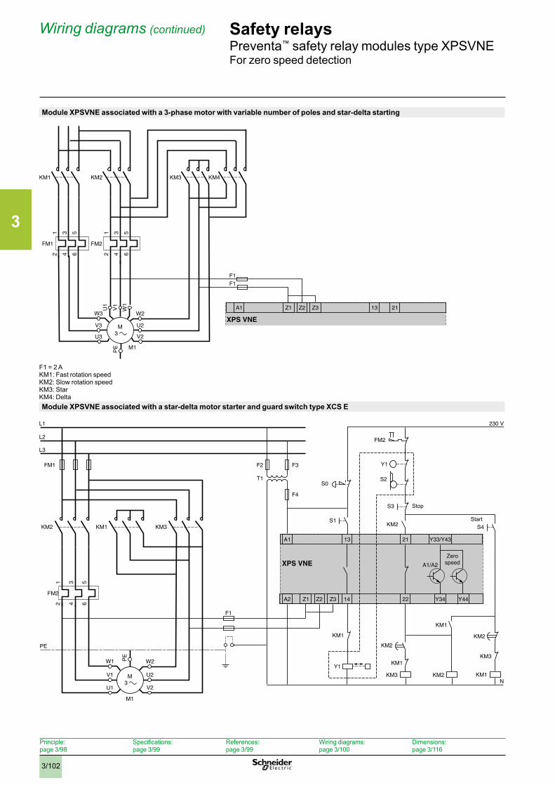
3
3/102
Safety relaysPreventa™ safety relay modules type XPSVNEFor zero speed detection
Module XPSVNE associated with a 3-phase motor with variable number of poles and star-delta starting
F1 = 2 AKM1: Fast rotation speedKM2: Slow rotation speedKM3: StarKM4: DeltaModule XPSVNE associated with a star-delta motor starter and guard switch type XCS E
M3
M1
PE
W3
U3
V3
W2
V2
U2
KM2
1 3 5
2 4 6
FM1
KM1
1 3 5
2 4 6
FM2
KM3
U1
W1
V1
KM4
Z3Z1A1 Z2 21
XPS VNE
13
F1F1
PE
PE
F1
M3
M1
W1
U1
V1
W2
V2
U2
KM1
1 3 5
2 4 6
FM2
FM1 F2 F3
F4
KM2 KM3
Z3Z1
A1
A2 Z2
L1
L2
L3
N
Y33/Y4321
22 Y34 Y44
XPS VNE A1/A2
14
13
S0
KM2 S4S1
230 V
S3
FM2
Y1
S2
KM2
KM1
T1
Y1
KM3
KM1KM3
KM2
KM1
KM1
KM2
Start
Stop
Zero speed
Wiring diagrams (continued)
Principle:page 3/98
Specifications:page 3/99
References:page 3/99
Wiring diagrams:page 3/100
Dimensions:page 3/116
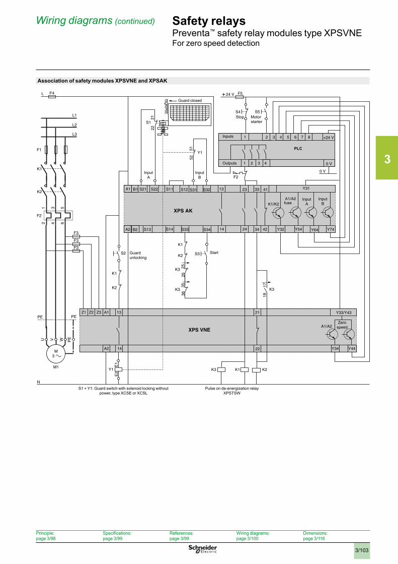
3
3/103
Safety relaysPreventa™ safety relay modules type XPSVNEFor zero speed detection
Association of safety modules XPSVNE and XPSAK
S13
S11
7 8
S33
L F4
1 43 5 6 +24 V
0 V321
2
4
+ 24 V
0 V
F5
S1
PE PE
F3
F3
F3
1 3 5
2 4 6
F2
F1
K2
K1
S14 S34
A1
A2 B2
L1
L2
L3
N
Y54
S31 33
3414 42
13 41B1 S32S21 Y31S12 23
Y64
XPS AKK1/K2
24
S22
S2
Z3Z1 A1
A2
Z2 21
22 Y34 Y44
XPS VNEA1/A2
14
13
Y1
K2
K1
K3
K3
K1
K2 1718
2526
E1
E2
5152
2122
3536
K1 K2K3
U W PEV
M3
M1
F2
S3
S4 S5
A1/A2
Y1
K3
Y32 Y74
Y33/Y43
S11
7 8
S33S13
Stop Motor starter
Guard closed
Inputs
Outputs
fuse
Zero speed
PLC
Guard unlocking
Start
S1 + Y1: Guard switch with solenoid locking without power, type XCSE or XCSL
Pulse on de-energization relayXPSTSW
Input A
Input B
Input A
Input B
Wiring diagrams (continued)
Principle:page 3/98
Specifications:page 3/99
References:page 3/99
Wiring diagrams:page 3/100
Dimensions:page 3/116
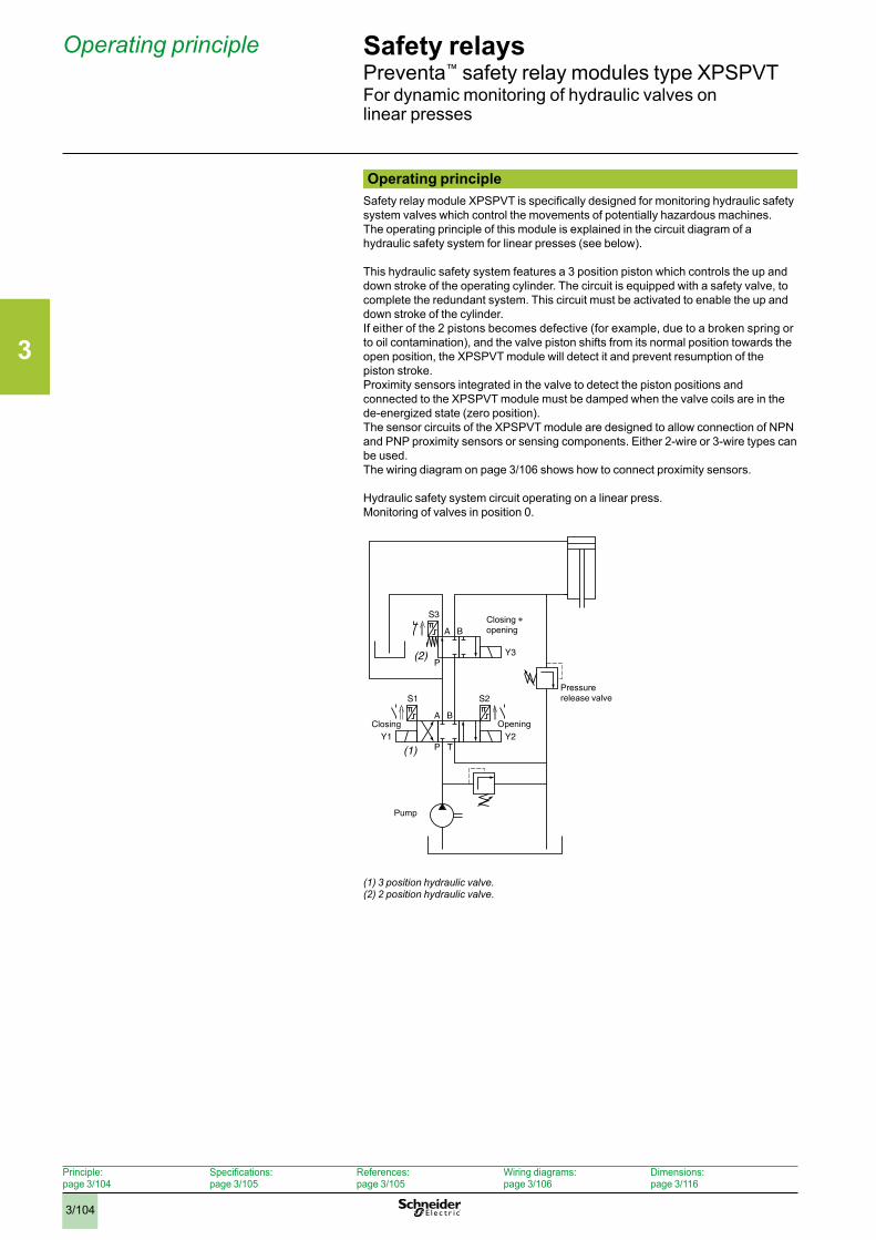
3
3/104
Safety relaysPreventa™ safety relay modules type XPSPVTFor dynamic monitoring of hydraulic valves on linear presses
Operating principleSafety relay module XPSPVT is specifically designed for monitoring hydraulic safety system valves which control the movements of potentially hazardous machines.The operating principle of this module is explained in the circuit diagram of a hydraulic safety system for linear presses (see below).
This hydraulic safety system features a 3 position piston which controls the up and down stroke of the operating cylinder. The circuit is equipped with a safety valve, to complete the redundant system. This circuit must be activated to enable the up and down stroke of the cylinder.If either of the 2 pistons becomes defective (for example, due to a broken spring or to oil contamination), and the valve piston shifts from its normal position towards the open position, the XPSPVT module will detect it and prevent resumption of the piston stroke.Proximity sensors integrated in the valve to detect the piston positions and connected to the XPSPVT module must be damped when the valve coils are in the de-energized state (zero position).The sensor circuits of the XPSPVT module are designed to allow connection of NPN and PNP proximity sensors or sensing components. Either 2-wire or 3-wire types can be used.The wiring diagram on page 3/106 shows how to connect proximity sensors.
Hydraulic safety system circuit operating on a linear press.Monitoring of valves in position 0.
(1) 3 position hydraulic valve .(2) 2 position hydraulic valve .
S3
A B
P(2) Y3
(1)
S2
Y2
S1
Y1
A B
P T
Pressure release valve
Opening
Pump
Closing + opening
Closing
Operating principle
Principle:page 3/104
Specifications:page 3/105
References:page 3/105
Wiring diagrams:page 3/106
Dimensions:page 3/116
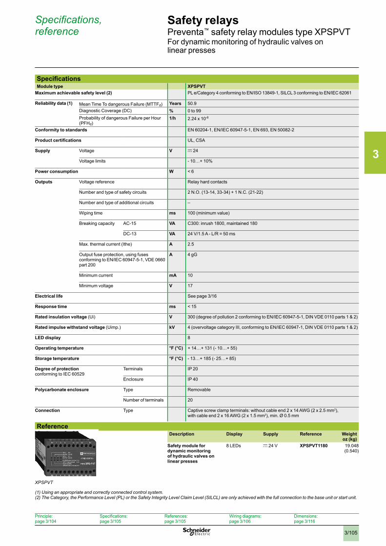
3
3/105
Safety relaysPreventa™ safety relay modules type XPSPVTFor dynamic monitoring of hydraulic valves on linear presses
SpecificationsModule type XPSPVT
Maximum achievable safety level (2) PL e/Category 4 conforming to EN/ISO 13849-1, SILCL 3 conforming to EN/IEC 62061
Reliability data (1) Mean Time To dangerous Failure (MTTFd) Years 50.9Diagnostic Coverage (DC) % 0 to 99Probability of dangerous Failure per Hour (PFHd)
1/h 2.24 x 10⁻⁸
Conformity to standards EN 60204-1, EN/IEC 60947-5-1, EN 693, EN 50082-2
Product certifications UL, CSA
Supply Voltage V c 24
Voltage limits - 10…+ 10%
Power consumption W < 6
Outputs Voltage reference Relay hard contacts
Number and type of safety circuits 2 N.O. (13-14, 33-34) + 1 N.C. (21-22)
Number and type of additional circuits –
Wiping time ms 100 (minimum value)
Breaking capacity AC-15 VA C300: inrush 1800, maintained 180
DC-13 VA 24 V/1.5 A - L/R = 50 ms
Max. thermal current (Ithe) A 2.5
Output fuse protection, using fuses conforming to EN/IEC 60947-5-1, VDE 0660 part 200
A 4 gG
Minimum current mA 10
Minimum voltage V 17
Electrical life See page 3/16
Response time ms < 15
Rated insulation voltage (Ui) V 300 (degree of pollution 2 conforming to EN/IEC 60947-5-1, DIN VDE 0110 parts 1 & 2)
Rated impulse withstand voltage (Uimp.) kV 4 (overvoltage category III, conforming to EN/IEC 60947-1, DIN VDE 0110 parts 1 & 2)
LED display 8
Operating temperature °F (°C) + 14…+ 131 (- 10…+ 55)
Storage temperature °F (°C) - 13…+ 185 (- 25…+ 85)
Degree of protection conforming to IEC 60529
Terminals IP 20
Enclosure IP 40
Polycarbonate enclosure Type Removable
Number of terminals 20
Connection Type Captive screw clamp terminals: without cable end 2 x 14 AWG (2 x 2.5 mm2), with cable end 2 x 16 AWG (2 x 1.5 mm2), min. Ø 0.5 mm
ReferenceDescription Display Supply Reference Weight
oz (kg)Safety module for dynamic monitoring of hydraulic valves on linear presses
8 LEDs c 24 V XPSPVT1180 19.048 (0.540)
Specifications, reference
XPSPVT
Principle:page 3/104
Specifications:page 3/105
References:page 3/105
Wiring diagrams:page 3/106
Dimensions:page 3/116
(1) Using an appropriate and correctly connected control system .(2) The Category, the Performance Level (PL) or the Safety Integrity Level Claim Level (SILCL) are only achieved with the full connection to the base unit or start unit .
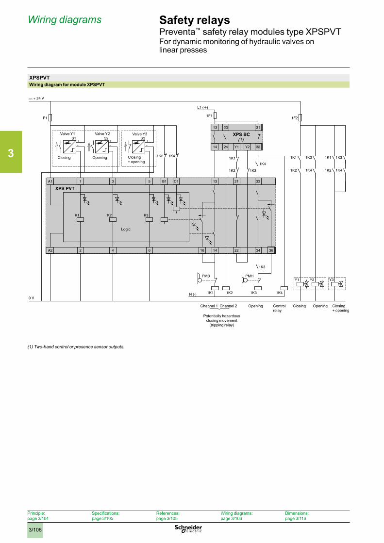
3
3/106
Safety relaysPreventa™ safety relay modules type XPSPVTFor dynamic monitoring of hydraulic valves on linear presses
XPSPVTWiring diagram for module XPSPVT
(1) Two-hand control or presence sensor outputs .
A1 1 3 5 B1 C1 13 21
221416A2 2 34 36
1K1
1K2 1K3
1K2
K1
33
XPS PVT
-+
S1
-+
S2
0 V
F11F1
1F2
-
6
K3
4
K2
+S3
1K4
1K4
1K2
1K1
Y1 Y2
13 23 31
14 24 32
XPS BC(1)
Y1
1K3
1K3
1K41K21K1
1K3
1K4 1K4
1K3
Y2
1K2
1K1
Y3
L1 (+)
N (-)
PMHPMB
Valve Y1 Valve Y2 Valve Y3
Closing Opening Closing + opening
Channel 1 Channel 2 Control relay
Opening Closing + opening
Potentially hazardous closing movement
(tripping relay)
OpeningClosing
Logic
Wiring diagrams
Principle:page 3/104
Specifications:page 3/105
References:page 3/105
Wiring diagrams:page 3/106
Dimensions:page 3/116
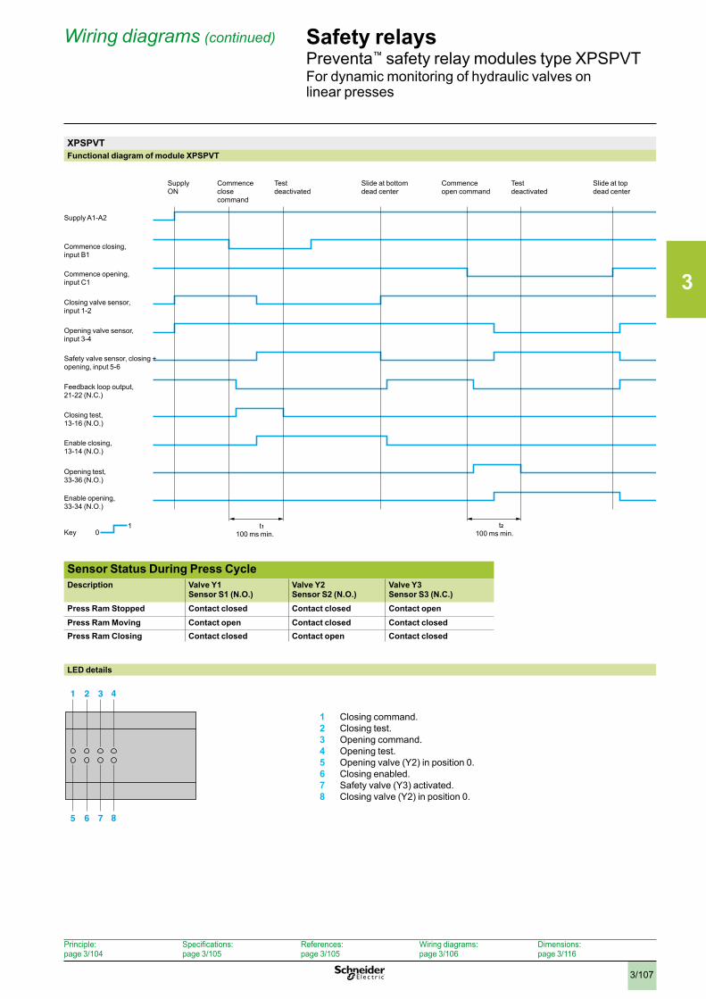
3
3/107
Safety relaysPreventa™ safety relay modules type XPSPVTFor dynamic monitoring of hydraulic valves on linear presses
XPSPVTFunctional diagram of module XPSPVT
LED details
1 Closing command.2 Closing test.3 Opening command.4 Opening test.5 Opening valve (Y2) in position 0.6 Closing enabled.7 Safety valve (Y3) activated.8 Closing valve (Y2) in position 0.
1 2 3 4
5 6 7 8
Sensor Status During Press Cycle Description Valve Y1
Sensor S1 (N.O.) Valve Y2Sensor S2 (N.O.)
Valve Y3 Sensor S3 (N.C.)
Press Ram Stopped Contact closed Contact closed Contact open Press Ram Moving Contact open Contact closed Contact closed Press Ram Closing Contact closed Contact open Contact closed
Wiring diagrams (continued)
Supply ON
Commence close command
Test deactivated
Slide at bottom dead center
Commence open command
Test deactivated
Slide at top dead center
t1100 ms min.
t2
100 ms min.1
Key 0
Supply A1-A2
Commence closing, input B1
Commence opening, input C1
Closing valve sensor,input 1-2
Opening valve sensor, input 3-4
Safety valve sensor, closing +opening, input 5-6
Feedback loop output, 21-22 (N.C.)
Closing test, 13-16 (N.O.)
Enable closing, 13-14 (N.O.)
Opening test, 33-36 (N.O.)
Enable opening,33-34 (N.O.)
Principle:page 3/104
Specifications:page 3/105
References:page 3/105
Wiring diagrams:page 3/106
Dimensions:page 3/116
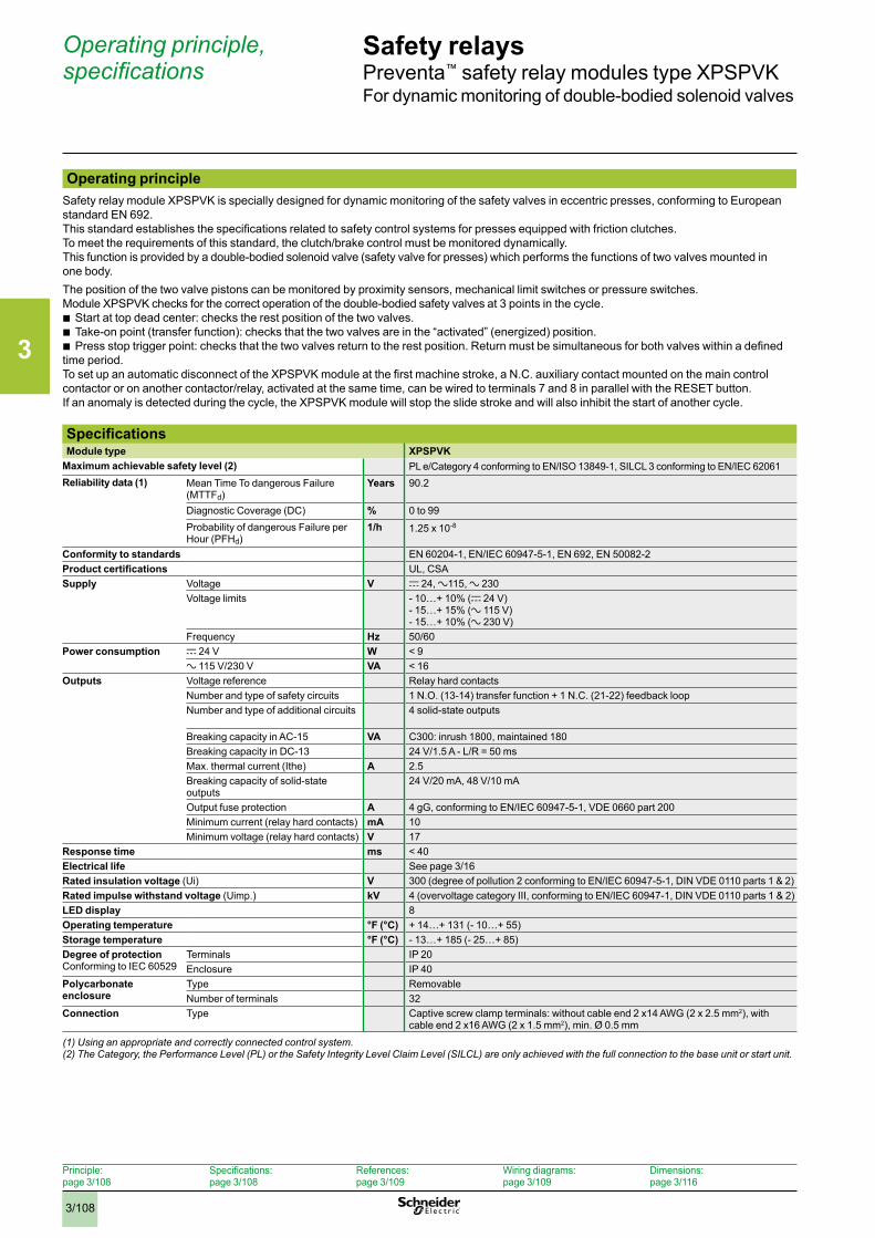
3
3/108
Safety relays Preventa™ safety relay modules type XPSPVKFor dynamic monitoring of double-bodied solenoid valves
Operating principleSafety relay module XPSPVK is specially designed for dynamic monitoring of the safety valves in eccentric presses, conforming to European standard EN 692.This standard establishes the specifications related to safety control systems for presses equipped with friction clutches.To meet the requirements of this standard, the clutch/brake control must be monitored dynamically.This function is provided by a double-bodied solenoid valve (safety valve for presses) which performs the functions of two valves mounted in one body.The position of the two valve pistons can be monitored by proximity sensors, mechanical limit switches or pressure switches.Module XPSPVK checks for the correct operation of the double-bodied safety valves at 3 points in the cycle.
b Start at top dead center: checks the rest position of the two valves. b Take-on point (transfer function): checks that the two valves are in the “activated” (energized) position. b Press stop trigger point: checks that the two valves return to the rest position. Return must be simultaneous for both valves within a defined
time period.To set up an automatic disconnect of the XPSPVK module at the first machine stroke, a N.C. auxiliary contact mounted on the main control contactor or on another contactor/relay, activated at the same time, can be wired to terminals 7 and 8 in parallel with the RESET button.If an anomaly is detected during the cycle, the XPSPVK module will stop the slide stroke and will also inhibit the start of another cycle.
SpecificationsModule type XPSPVK
Maximum achievable safety level (2) PL e/Category 4 conforming to EN/ISO 13849-1, SILCL 3 conforming to EN/IEC 62061 Reliability data (1) Mean Time To dangerous Failure
(MTTFd)Years 90.2
Diagnostic Coverage (DC) % 0 to 99Probability of dangerous Failure per Hour (PFHd)
1/h 1.25 x 10⁻⁸
Conformity to standards EN 60204-1, EN/IEC 60947-5-1, EN 692, EN 50082-2Product certifications UL, CSASupply Voltage V c 24, a115, a 230
Voltage limits - 10…+ 10% (c 24 V)- 15…+ 15% (a 115 V)- 15…+ 10% (a 230 V)
Frequency Hz 50/60Power consumption c 24 V W < 9
a 115 V/230 V VA < 16Outputs Voltage reference Relay hard contacts
Number and type of safety circuits 1 N.O. (13-14) transfer function + 1 N.C. (21-22) feedback loopNumber and type of additional circuits 4 solid-state outputs
Breaking capacity in AC-15 VA C300: inrush 1800, maintained 180Breaking capacity in DC-13 24 V/1.5 A - L/R = 50 msMax. thermal current (Ithe) A 2.5Breaking capacity of solid-state outputs
24 V/20 mA, 48 V/10 mA
Output fuse protection A 4 gG, conforming to EN/IEC 60947-5-1, VDE 0660 part 200Minimum current (relay hard contacts) mA 10Minimum voltage (relay hard contacts) V 17
Response time ms < 40Electrical life See page 3/16Rated insulation voltage (Ui) V 300 (degree of pollution 2 conforming to EN/IEC 60947-5-1, DIN VDE 0110 parts 1 & 2)Rated impulse withstand voltage (Uimp.) kV 4 (overvoltage category III, conforming to EN/IEC 60947-1, DIN VDE 0110 parts 1 & 2)LED display 8Operating temperature °F (°C) + 14…+ 131 (- 10…+ 55)Storage temperature °F (°C) - 13…+ 185 (- 25…+ 85)Degree of protectionConforming to IEC 60529
Terminals IP 20Enclosure IP 40
Polycarbonate enclosure
Type RemovableNumber of terminals 32
Connection Type Captive screw clamp terminals: without cable end 2 x14 AWG (2 x 2.5 mm2), with cable end 2 x16 AWG (2 x 1.5 mm2), min. Ø 0.5 mm
Operating principle, specifications
Principle:page 3/108
Specifications:page 3/108
References:page 3/109
Wiring diagrams:page 3/109
Dimensions:page 3/116
(1) Using an appropriate and correctly connected control system .(2) The Category, the Performance Level (PL) or the Safety Integrity Level Claim Level (SILCL) are only achieved with the full connection to the base unit or start unit .
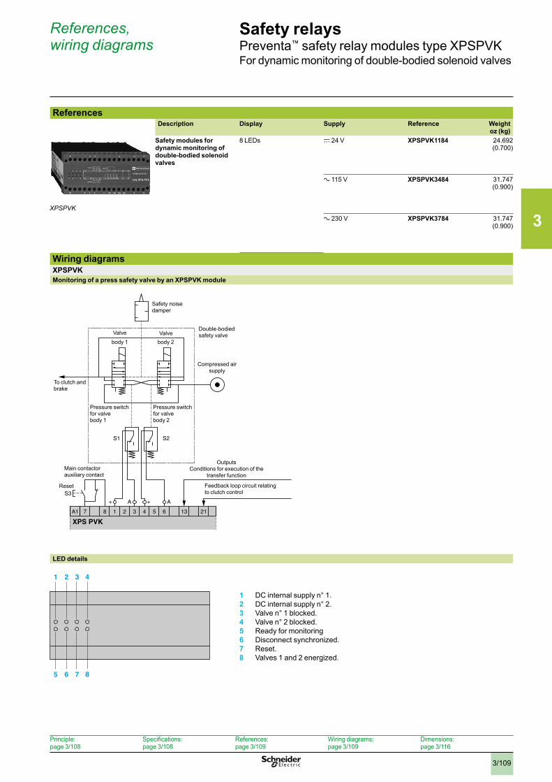
3
3/109
Safety relays Preventa™ safety relay modules type XPSPVKFor dynamic monitoring of double-bodied solenoid valves
ReferencesDescription Display Supply Reference Weight
oz (kg)Safety modules for dynamic monitoring of double-bodied solenoid valves
8 LEDs c 24 V
XPSPVK1184 24.692 (0.700)
a 115 V
XPSPVK3484 31.747 (0.900)
a 230 V
XPSPVK3784 31.747 (0.900)
Wiring diagramsXPSPVKMonitoring of a press safety valve by an XPSPVK module
LED details
1 DC internal supply n° 1.2 DC internal supply n° 2.3 Valve n° 1 blocked.4 Valve n° 2 blocked.5 Ready for monitoring6 Disconnect synchronized.7 Reset.8 Valves 1 and 2 energized.
XPSPVK
13 21A1 1 2 37 4 5 6
S3
S1 S2
A+ A+
8
XPS PVK
Safety noise damper
OutputsConditions for execution of the
transfer function
Double-bodied safety valve
Compressed air supply
To clutch and brake
Valve Valvebody 1 body 2
Pressure switch for valve body 1
Pressure switch for valve body 2
Feedback loop circuit relating to clutch control
Reset
Main contactor auxiliary contact
1 2 3 4
5 6 7 8
References, wiring diagrams
Principle:page 3/108
Specifications:page 3/108
References:page 3/109
Wiring diagrams:page 3/109
Dimensions:page 3/116
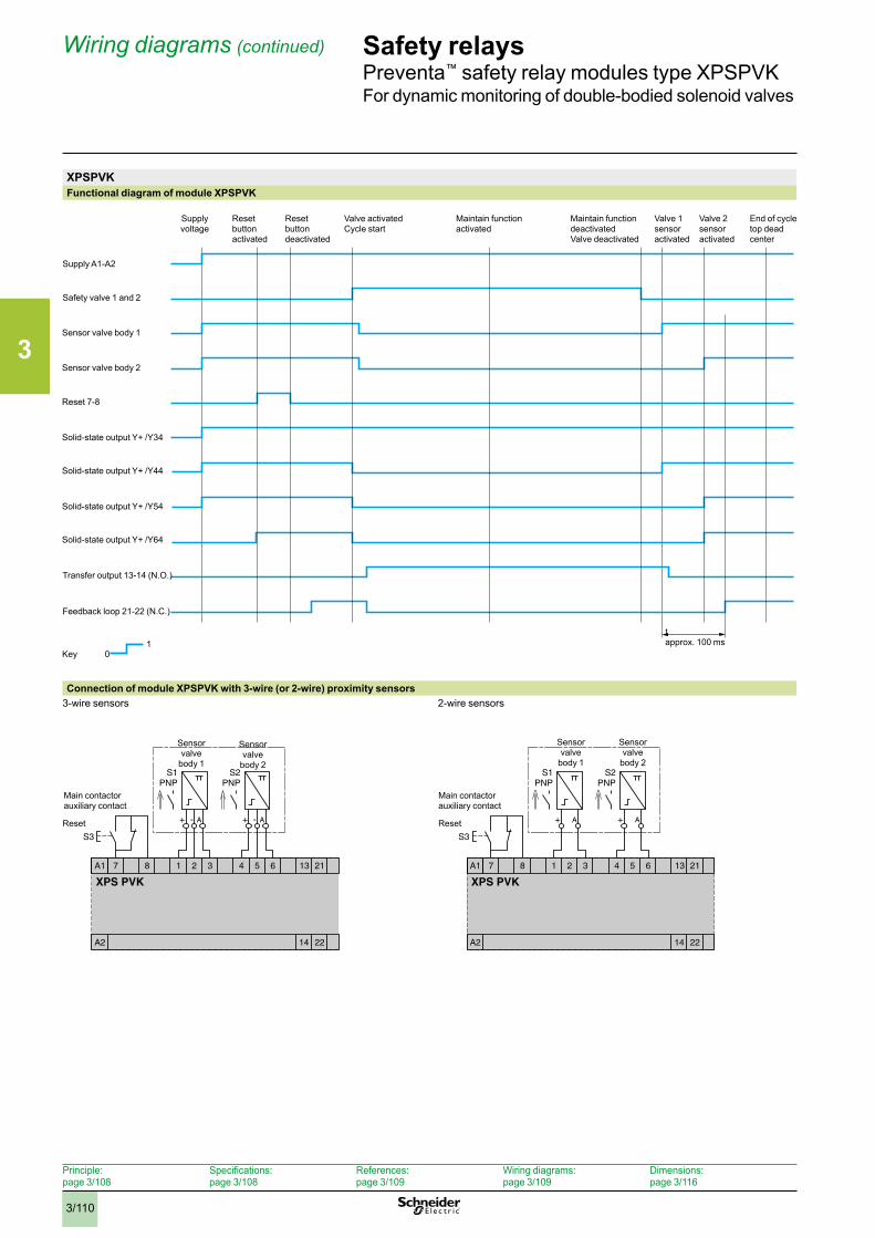
3
3/110
Safety relays Preventa™ safety relay modules type XPSPVKFor dynamic monitoring of double-bodied solenoid valves
XPSPVKFunctional diagram of module XPSPVK
Connection of module XPSPVK with 3-wire (or 2-wire) proximity sensors3-wire sensors 2-wire sensors
Supply A1-A2
Safety valve 1 and 2
Sensor valve body 1
Sensor valve body 2
Reset 7-8
Solid-state output Y+ /Y34
Solid-state output Y+ /Y44
Solid-state output Y+ /Y54
Solid-state output Y+ /Y64
Transfer output 13-14 (N.O.)
Feedback loop 21-22 (N.C.)
Key 01
tapprox. 100 ms
Supply voltage
Resetbuttonactivated
Reset button deactivated
Valve activatedCycle start
Maintain function activated
Maintain function deactivatedValve deactivated
Valve 1 sensor activated
Valve 2 sensor activated
End of cycle top dead center
A2
XPS PVK
13 21
14 22
A1 1 2 37 8 4 5 6
S3
PNPS1
- A+
PNPS2
- A+
Main contactor auxiliary contact
Reset
Sensor valve
body 2
Sensor valve
body 1
S3
PNPS1
PNPS2
A2
XPS PVK
13 21
14 22
A1 1 2 37 8 4 5 6
A+ A+
Main contactor auxiliary contact
Sensor valve
body 2
Sensor valve
body 1
Reset
Wiring diagrams (continued)
Principle:page 3/108
Specifications:page 3/108
References:page 3/109
Wiring diagrams:page 3/109
Dimensions:page 3/116
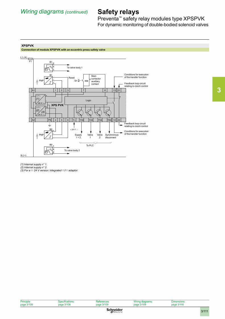
3
3/111
Safety relays Preventa™ safety relay modules type XPSPVKFor dynamic monitoring of double-bodied solenoid valves
XPSPVKConnection of module XPSPVK with an eccentric press safety valve
(1) Internal supply n° 1 .(2) Internal supply n° 2 .(3) For a c 24 V version: integrated c/c adaptor .
Y34 Y44 Y64Y54
A1 1 3 7 1382 21
A2 PE
-
-
-
+
41
2
P
+
+
B1
B1
PNP
/
24 V XPS PVK
/
24 V
4 5 Y+6 14 22
-+B2
PNP
S1 KM
B2
4
(1)
2
1
P
L1 (+)
N (–)
F1
(2)(3)
To valve body 1
ResetMain contactor auxiliary contact
Feedback loop circuit relating to clutch control
Conditions for execution of the transfer function
Feedback loop circuit relating to clutch control
Conditions for execution of the transfer function
Supply1 + 2
Valve 1
Valve 2
Synchronous disconnect
To PLC
To valve body 2
Logic
Wiring diagrams (continued)
Principle:page 3/108
Specifications:page 3/108
References:page 3/109
Wiring diagrams:page 3/109
Dimensions:page 3/116
3
3/112
Safety relaysPreventa™ safety relay modules type XPSOTFor safety stop with automatic overtravel monitoring and control
Operating principleSafety relay module XPSOT is used on eccentric presses to monitor overtravel and ensure that the press slide stops in a non-hazardous position, that is, top dead center (TDC) during normal (non-emergency) operation. Use of this module, designed in accordance with standard EN 692 relating to mechanical press safety, makes it possible to create a redundant, self-monitoring control system. The two essential functions of this safety module are to:
b Trigger the end of cycle stop sequences slightly before top dead center (at point A) so as to come to complete stop at TDC. After TDC, the permissible overtravel is approximately 10°. The safety module immediately detects any overtravel. Overtravel is indicative of braking device deterioration and, in this case, jog mode must be used to move the slide back to TDC. The next cycle will be inhibited to allow maintenance to be performed on the braking device (cam 1).
b Take over control monitoring during the dangerous part of the cycle (slide downstroke). Any stop instruction issued between TDC (0°) and point C (approximately 150° after TDC) causes an immediate stop of the press. This approximate value of 150° corresponds to the 0.315” (8mm) tool closure dimension (safety point). When a stop instruction is issued after this safety point, the press completes the cycle and comes to a complete stop at TDC (cam 2).
Control of the hazardous part of the cycle (generally the slide downstroke) is usually activated from a two-hand control station associated with a safety module (type XPSBC) monitoring this station to qualify as a category 4 control system according to standard EN 954-1/ISO 13849-1.
Overtravel monitoring is performed on each cycle by safety module XPSOT.
Operating principle
Principle:page 3/112
Specifications:page 3/114
References:page 3/114
Wiring diagrams:page 3/115
Dimensions:page 3/116
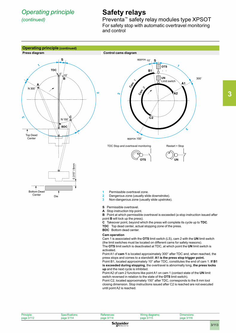
3
3/113
Safety relaysPreventa™ safety relay modules type XPSOTFor safety stop with automatic overtravel monitoring and control
Operating principle (continued)Press diagram Control cams diagram
1 Permissible overtravel zone.2 Dangerous zone (usually slide downstroke).3 Non-dangerous zone (usually slide upstroke).
S Permissible overtravel.A Stop instruction trip point.B Point at which permissible overtravel is exceeded (a stop instruction issued after point B will lock up the press).C Takeover point, beyond which the press will complete its cycle up to TDC.TDC Top dead center, actual stopping zone of the press.BDC Bottom dead center.Cam operationCam 1 is associated with the OTS limit switch (LS), cam 2 with the UN limit switch (the limit switches must be located on different cams for safety reasons).The OTS limit switch is deactivated at TDC, at which point the UN limit switch is activated.Point A1 of cam 1 is located approximately 300° after TDC and, when reached, the press stops and comes to a standstill: A1 is the press stop trigger point.Point B1, located approximately 10° after TDC, constitutes the end of cam 1: If B1 is exceeded during stopping, the overtravel is abnormally long, the press locks up and the next cycle is inhibited.Point A2 of cam 2 functions like point A1 on cam 1 (contact state of the UN limit switch reversed in relation to the state of the OTS limit switch).Point C2, located approximately 150° after TDC, corresponds to the 8 mm tool closing dimension. Stop instructions issued after C2 is reached are not executed until point A2 is reached.
Operating principle (continued)
Top Dead Center
Bottom Dead Center Die
0.31
5” /
8mm
TDC
BDC
TDC Stop and overtravel monitoring Restart + Stop
approx.
approx.
Cam
Cam
OTS
UNLimit switch
Principle:page 3/112
Specifications:page 3/114
References:page 3/114
Wiring diagrams:page 3/115
Dimensions:page 3/116
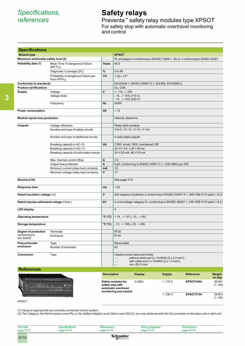
3
3/114
Safety relaysPreventa™ safety relay modules type XPSOTFor safety stop with automatic overtravel monitoring and control
SpecificationsModule type XPSOT
Maximum achievable safety level (2) PL e/Category 4 conforming to EN/ISO 13849-1, SILCL 3 conforming to EN/IEC 62061 Reliability data (1) Mean Time To dangerous Failure
(MTTFd)Years 60.9
Diagnostic Coverage (DC) % 0 to 99Probability of dangerous Failure per Hour (PFHd)
1/h 1.33 x 10⁻⁸
Conformity to standards EN 60204-1, EN/IEC 60947-5-1, EN 692, EN 50082-2Product certifications UL, CSASupply Voltage V a 115, a 230
Voltage limits - 15…+ 15% (115 V)- 15…+ 10% (230 V)
Frequency Hz 50/60
Power consumption VA < 12
Module inputs fuse protection Internal, electronic
Outputs Voltage reference Relay hard contactsNumber and type of safety circuits 3 N.O. (11-12, 11-13, 11-14)
Number and type of additional circuits 4 solid-state outputs
Breaking capacity in AC-15 VA C300: inrush 1800, maintained 180Breaking capacity in DC-13 24 V/1.5 A - L/R = 50 msBreaking capacity of solid-state outputs 24 V/20 mA, 48 V/10 mA
Max. thermal current (Ithe) A 2.5Output fuse protection A 4 gG, conforming to EN/IEC 60947-5-1, VDE 0660 part 200Minimum current (relay hard contacts) mA 10Minimum voltage (relay hard contacts) V 17
Electrical life See page 3/16
Response time ms < 20
Rated insulation voltage (Ui) V 300 (degree of pollution 2 conforming to EN/IEC 60947-5-1, DIN VDE 0110 parts 1 & 2)
Rated impulse withstand voltage (Uimp.) kV 4 (overvoltage category III, conforming to EN/IEC 60947-1, DIN VDE 0110 parts 1 & 2)
LED display 4
Operating temperature °F (°C) + 14…+ 131 (- 10…+ 55)
Storage temperature °F (°C) - 13…+ 185 (- 25…+ 85)
Degree of protectionconforming to IEC 60529
Terminals IP 20Enclosure IP 40
Polycarbonate enclosure
Type RemovableNumber of terminals 42
Connection Type
Captive screw clamp terminals: - - without cable end 2 x 14 AWG (2 x 2.5 mm2), - - with cable end 2 x 16 AWG (2 x 1.5 mm2), - - min. Ø 0.5 mm
ReferencesDescription Display Supply Reference Weight
oz (kg)Safety modules for safety stop with automatic overtravel monitoring and control
4 LEDs a 115 V XPSOT3444 38.801 (1.100)
a 230 V XPSOT3744 38.801 (1.100)
Specifications, references
XPSOT
Principle:page 3/112
Specifications:page 3/114
References:page 3/114
Wiring diagrams:page 3/115
Dimensions:page 3/116
(1) Using an appropriate and correctly connected control system .(2) The Category, the Performance Level (PL) or the Safety Integrity Level Claim Level (SILCL) are only achieved with the full connection to the base unit or start unit .
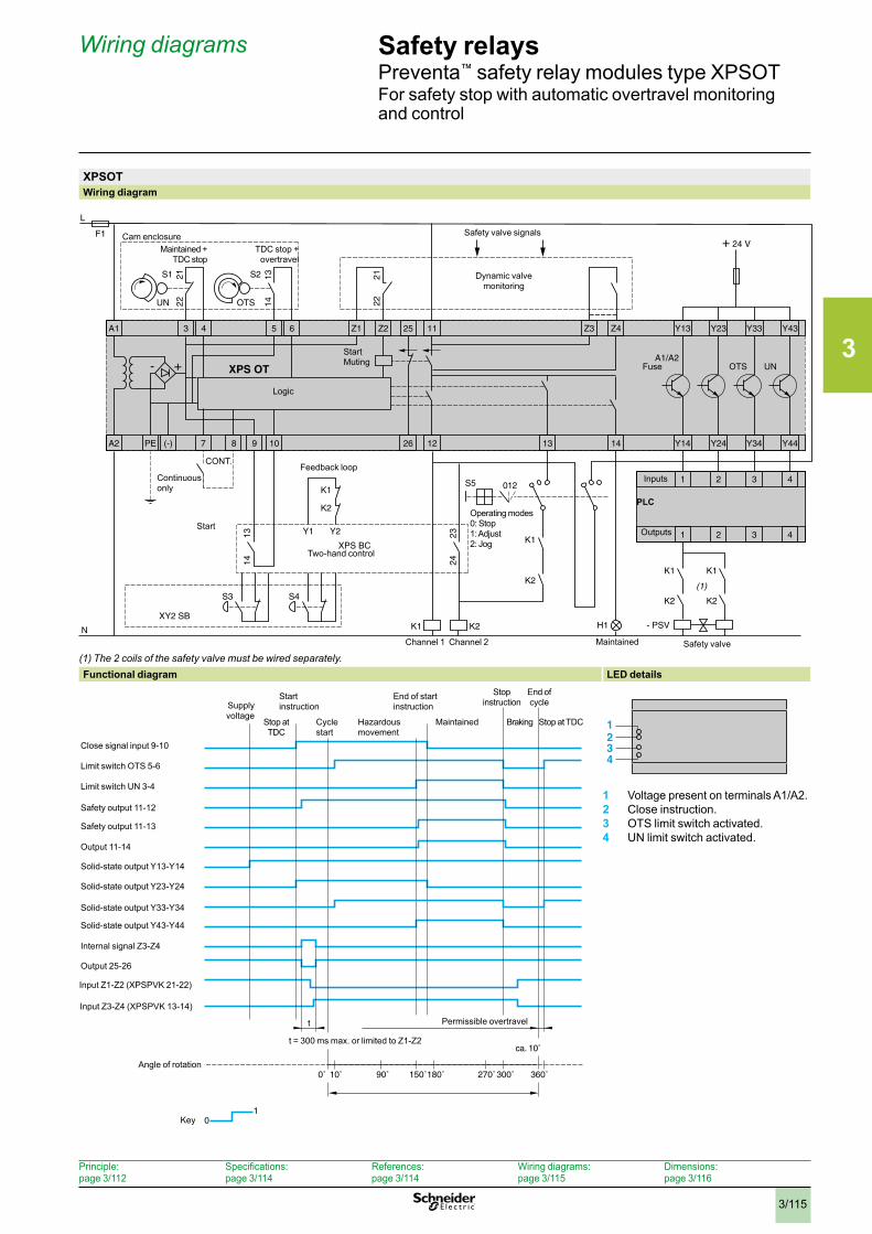
3
3/115
Safety relaysPreventa™ safety relay modules type XPSOTFor safety stop with automatic overtravel monitoring and control
XPSOTWiring diagram
(1) The 2 coils of the safety valve must be wired separately .Functional diagram LED details
1 Voltage present on terminals A1/A2.2 Close instruction.3 OTS limit switch activated.4 UN limit switch activated.
A2 PE
F1
L
+ 24 V
N
- +
K2
S1
H1
XPS OT
A1 3 4 5 6 25Z1 Z2 Z3 Z411
122610987(-) 13 14
Y43
Y44
Y23
Y24
Y13
Y14
Y33
Y34
A1/A2
1 432
1 432
UN OTS
S2
Y2Y1
S3 S4
012S5
K1
K2
XY2 SB
XPS BC
K1
K1
K2
2221 13
14 2221
1314
2324
- PSV
K1
K2
K1
K2
(1)
Maintained + TDC stop
Cam enclosureTDC stop +
overtravel
Continuous only
Safety valve signals
Dynamic valvemonitoring
Logic
StartMuting Fuse OTS UN
Inputs
Outputs
Operating modes0: Stop1: Adjust2: Jog
Feedback loop
Two-hand control
Start
Maintained Safety valve Channel 1 Channel 2
PLC
CONT.
1234
Input Z1-Z2 (XPSPVK 21-22)
Input Z3-Z4 (XPSPVK 13-14)
Key
Output 25-26
Output 11-14
Solid-state output Y13-Y14
Solid-state output Y23-Y24
Solid-state output Y33-Y34
Solid-state output Y43-Y44
Internal signal Z3-Z4
Limit switch OTS 5-6
Limit switch UN 3-4
Safety output 11-12
Safety output 11-13
Close signal input 9-10
Start instruction
End of start instruction
End of cycleSupply
voltageMaintainedHazardous
movementCycle start
Braking
Stop instruction
Angle of rotation
Stop at TDC
t = 300 ms max. or limited to Z1-Z2
Permissible overtravel
Stop atTDC
Wiring diagrams
Principle:page 3/112
Specifications:page 3/114
References:page 3/114
Wiring diagrams:page 3/115
Dimensions:page 3/116

3
3/116
Dimensions Safety relaysPreventa™ safety relay modulesAM1 DP200 rail mounting
DimensionsXPSACpppp, XPSAFpppp, XPSAFLpppp, XPSDMBpppp, XPSVCpppp, XPSEDA
XPSACppppP, XPSABVppppP, XPSAXEppppP, XPSAFpppP, XPSAFLppppP, XPSBCEppppP, XPSBFppppP, XPSECMEppppP, XPSDMBppppP, XPSVCppppP
22,5
99
114 22,5114
99
XPSABVppppC, XPSAXEppppC, XPSBCEppppC, XPSECMEppppC XPSAKpppp, XPSAVpppp, XPSCMpppp, XPSDMEpppp, XPSATEpppp, XPSECPEppppP
4.49114
1.7745
3.9099
XPSAKppppP, XPSAVppppP, XPSCMppppP, XPSTSAppppP, XPSTSWppppP, XPSDMEppppP, XPSATEppppP, XPSVNEppppP
XPSAKppppC, XPSAVppppC, XPSCMppppC, XPSTSAppppC, XPSTSWppppC, XPSDMEppppC, XPSATEppppC, XPSVNEppppC
4.49114
1.7745
3.9099
INCHESMillimietersDual Dimensions:
0.8922.5
4.49114
3.9099
0.8922.5
4.49114
3.9099
0.8922.5
4.49114
4.37111
4.49114
1.7745
3.9099
4.49114
1.7745
3.9099
1.3835
1.7745
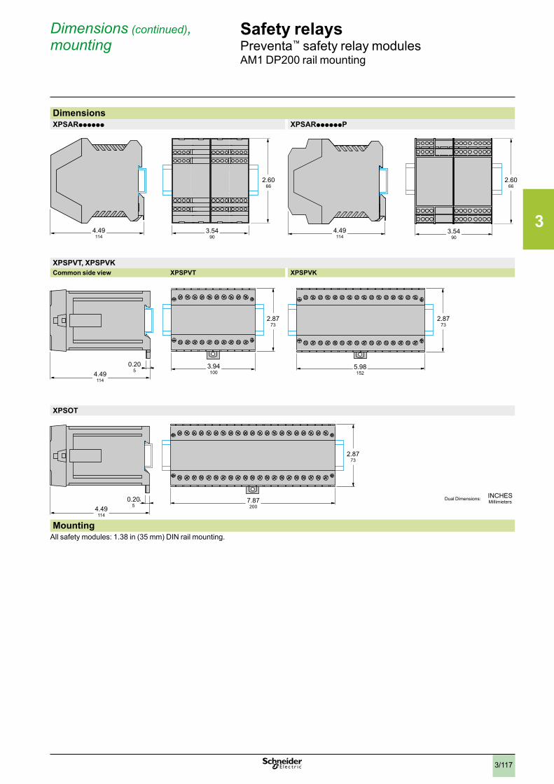
3
3/117
152
73
118200
73
5
100
73
1185
114 90
99
114 90
99
Dimensions (continued), mounting
Safety relaysPreventa™ safety relay modulesAM1 DP200 rail mounting
DimensionsXPSARpppppp XPSARppppppP
XPSPVT, XPSPVKCommon side view XPSPVT XPSPVK
XPSOT
MountingAll safety modules: 1.38 in (35 mm) DIN rail mounting.
4.49114
4.49114
4.49114
3.5490
3.94100
7.87200
0.205
0.205
2.8773
2.8773
2.8773
5.98152
2.6066
2.6066
4.49114
3.5490
INCHESMillimietersDual Dimensions:
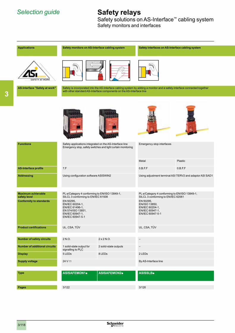
3
3/118
Safety relaysSafety solutions on AS-Interface™ cabling systemSafety monitors and interfaces
Selection guide
Applications
Safety monitors on AS-Interface cabling system Safety interfaces on AS-Interface cabling system
AS-Interface "Safety at work"
Safety is incorporated into the AS-Interface cabling system by adding a monitor and a safety interface connected together with other standard AS-Interface components on the AS-Interface line
Functions Safety applications integrated on the AS-Interface lineEmergency stop, safety switches and light curtain monitoring
Emergency stop interfaces
Interfaces for safety products Interfaces premounted in Emergency stop mushroom head pushbutton stations XAL K
Interfaces for mounting in enclosure for Harmony® Ø 22 mm Emergency stop mushroom head pushbuttons
Metal Plastic 1 x M12 entry 2 x M12 entries 1 x ISO M16 entry 1 x M12 entry Connector
AS-Interface profile 7.F 0.B.F.F 0.B.F.F 0.B.F.F 0.B.F.F 0.B.F.F 0.B.F.F
Addressing Using configuration software ASISWIN2 Using adjustment terminal ASI TERV2 and adaptor ASI SAD1
Using adjustment terminal ASI TERV2 and adaptor ASI SAD1 Using adjustment terminal ASI TERV2
Maximum achievable safety level
PL e/Category 4 conforming to EN/ISO 13849-1, SILCL 3 conforming to EN/IEC 61508
PL e/Category 4 conforming to EN/ISO 13849-1, SILCL 3 conforming to EN/IEC 62061
PL e/Category 4 conforming to EN/ISO 13849-1, SILCL 3 conforming to EN/IEC 62061
PL e/Category 4 conforming to EN/ISO 13849-1, SILCL 3 conforming to EN/IEC 62061
Conformity to standards EN 50295,EN/IEC 60204-1,EN/IEC 61496-1,EN 574/ISO 13851,EN/IEC 60947-1,EN/IEC 60947-5-1
EN 50295,EN/ISO 13850,EN/IEC 60204-1,EN/IEC 60947-1,EN/IEC 60947-5-1
EN 50295,EN/IEC 60204-1,EN 1088/ISO 14119,EN 574/ISO 13851,EN/IEC 61496-1,EN/IEC 60947-5-3,EN/IEC 60947-1,EN/IEC 60947-5-1
EN 50295,EN/ISO 13850,EN/IEC 60204-1,EN/IEC 60947-1,EN/IEC 60947-5-1
Product certifications UL, CSA, TÜV UL, CSA, TÜV UL, CSA, TÜV UL, CSA, TÜV
Number of safety circuits 2 N.O. 2 x 2 N.O. – – –
Number of additional circuits 1 solid-state output for signalling to PLC
2 solid-state outputs – – –
Display 5 LEDs 8 LEDs 2 LEDs 2 LEDs –
Supply voltage 24 V c By AS-Interface line By AS-Interface line By AS-Interface line
Type ASISAFEMON1p ASISAFEMON2p ASISSLBp ASISSLCp ASISSLLS ASISEp1C ASISSLEp
Pages 3/122 3/126 3/126 3/126
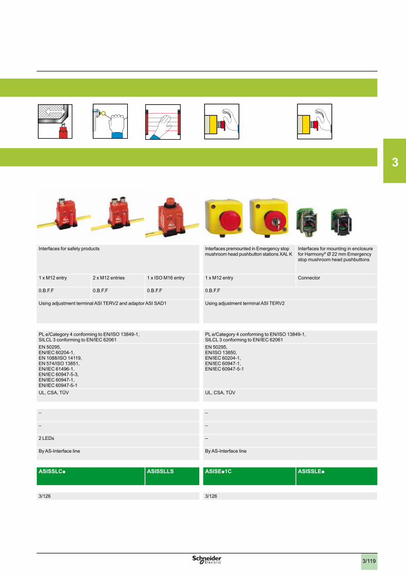
3
3/119
Applications
Safety monitors on AS-Interface cabling system Safety interfaces on AS-Interface cabling system
AS-Interface "Safety at work"
Safety is incorporated into the AS-Interface cabling system by adding a monitor and a safety interface connected together with other standard AS-Interface components on the AS-Interface line
Functions Safety applications integrated on the AS-Interface lineEmergency stop, safety switches and light curtain monitoring
Emergency stop interfaces
Interfaces for safety products Interfaces premounted in Emergency stop mushroom head pushbutton stations XAL K
Interfaces for mounting in enclosure for Harmony® Ø 22 mm Emergency stop mushroom head pushbuttons
Metal Plastic 1 x M12 entry 2 x M12 entries 1 x ISO M16 entry 1 x M12 entry Connector
AS-Interface profile 7.F 0.B.F.F 0.B.F.F 0.B.F.F 0.B.F.F 0.B.F.F 0.B.F.F
Addressing Using configuration software ASISWIN2 Using adjustment terminal ASI TERV2 and adaptor ASI SAD1
Using adjustment terminal ASI TERV2 and adaptor ASI SAD1 Using adjustment terminal ASI TERV2
Maximum achievable safety level
PL e/Category 4 conforming to EN/ISO 13849-1, SILCL 3 conforming to EN/IEC 61508
PL e/Category 4 conforming to EN/ISO 13849-1, SILCL 3 conforming to EN/IEC 62061
PL e/Category 4 conforming to EN/ISO 13849-1, SILCL 3 conforming to EN/IEC 62061
PL e/Category 4 conforming to EN/ISO 13849-1, SILCL 3 conforming to EN/IEC 62061
Conformity to standards EN 50295,EN/IEC 60204-1,EN/IEC 61496-1,EN 574/ISO 13851,EN/IEC 60947-1,EN/IEC 60947-5-1
EN 50295,EN/ISO 13850,EN/IEC 60204-1,EN/IEC 60947-1,EN/IEC 60947-5-1
EN 50295,EN/IEC 60204-1,EN 1088/ISO 14119,EN 574/ISO 13851,EN/IEC 61496-1,EN/IEC 60947-5-3,EN/IEC 60947-1,EN/IEC 60947-5-1
EN 50295,EN/ISO 13850,EN/IEC 60204-1,EN/IEC 60947-1,EN/IEC 60947-5-1
Product certifications UL, CSA, TÜV UL, CSA, TÜV UL, CSA, TÜV UL, CSA, TÜV
Number of safety circuits 2 N.O. 2 x 2 N.O. – – –
Number of additional circuits 1 solid-state output for signalling to PLC
2 solid-state outputs – – –
Display 5 LEDs 8 LEDs 2 LEDs 2 LEDs –
Supply voltage 24 V c By AS-Interface line By AS-Interface line By AS-Interface line
Type ASISAFEMON1p ASISAFEMON2p ASISSLBp ASISSLCp ASISSLLS ASISEp1C ASISSLEp
Pages 3/122 3/126 3/126 3/126
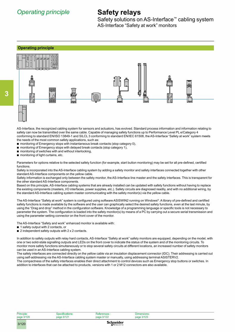
3
3/120
Safety relaysSafety solutions on AS-Interface™ cabling systemAS-Interface “Safety at work” monitors
Operating principle
AS-Interface, the recognized cabling system for sensors and actuators, has evolved. Standard process information and information relating to safety can now be transmitted over the same cable. Capable of managing safety functions up to Performance Level PL e/Category 4 conforming to standard EN/ISO 13849-1 and SILCL 3 conforming to standard EN/IEC 61508, the AS-Interface “Safety at work” system meets the needs of the most common safety applications, such as:
b monitoring of Emergency stops with instantaneous break contacts (stop category 0), b monitoring of Emergency stops with delayed break contacts (stop category 1), b monitoring of switches with and without interlocking, b monitoring of light curtains, etc.
Parameters for options relative to the selected safety function (for example, start button monitoring) may be set for all pre-defined, certified functions. Safety is incorporated into the AS-Interface cabling system by adding a safety monitor and safety interfaces connected together with other standard AS-Interface components on the yellow cable. Safety information is exchanged only between the safety monitor, the AS-Interface line master and the safety interfaces. This is transparent for the other standard AS-Interface components. Based on this principle, AS-Interface cabling systems that are already installed can be updated with safety functions without having to replace the existing components (masters, I/O interfaces, power supplies, etc.). Safety circuits are diagnosed readily, and with no additional wiring, by the standard AS-Interface cabling system master communicating with the safety monitor(s) via the yellow cable.
The AS-Interface “Safety at work” system is configured using software ASISWIN2 running on Windows®. A library of pre-defined and certified safety functions is made available by the software and the user can graphically select the desired safety functions, even at the last minute, by using the “Drag and drop” method in the configuration software. Knowledge of a programming language or specific tools is not necessary to parameter the system. The configuration is loaded into the safety monitor(s) by means of a PC by carrying out a secure serial transmission and using the parameter setting connector on the front cover of the monitor.
The AS-Interface “Safety and work” enhanced monitor is available with: b 1 safety output with 2 contacts, or b 2 independent safety outputs with 2 x 2 contacts.
In addition to safety outputs with relay hard contacts, AS-Interface “Safety at work” safety monitors are equipped, depending on the model, with one or two solid-state signalling outputs and LEDs on the front cover to indicate the status of the system and of the monitoring circuits. To monitor more safety functions simultaneously or to stop several safety circuits at different locations, an increased number of safety monitors can be used in an AS-Interface cabling system.The safety interfaces are connected directly on the yellow cable via an insulation displacement connector (IDC). Their addressing is carried out using self-addressing via the AS-Interface cabling system master or manually, using addressing terminal ASISTERV2. The compactness of the safety interfaces enables their direct attachment to control devices such as Emergency stop buttons or switches. In addition to interfaces that can be attached to products, versions with 1 or 2 M12 connectors are also available.
Operating principle
Principle: page 3/120
Specifications: page 3/121
References : page 3/122
Dimensions: page 3/123
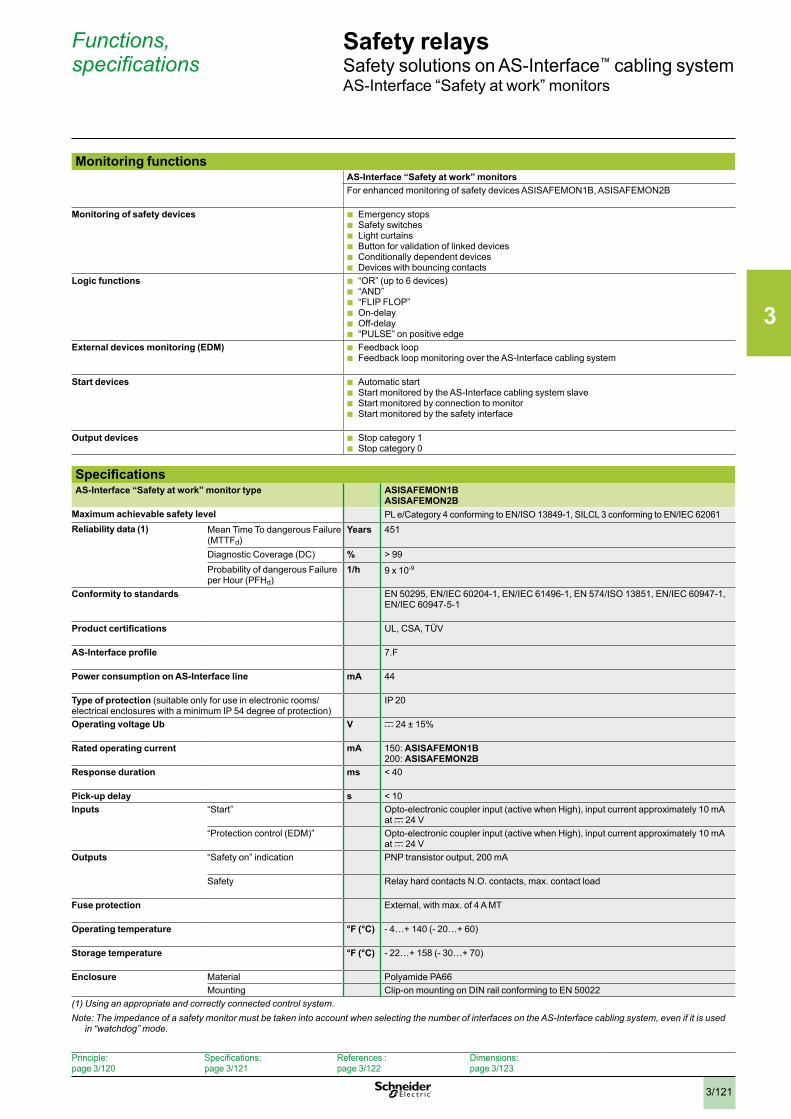
3
3/121
Safety relaysSafety solutions on AS-Interface™ cabling systemAS-Interface “Safety at work” monitors
Monitoring functionsAS-Interface “Safety at work” monitorsFor enhanced monitoring of safety devices ASISAFEMON1B, ASISAFEMON2B
Monitoring of safety devices b Emergency stops b Safety switches b Light curtains b Button for validation of linked devices b Conditionally dependent devices b Devices with bouncing contacts
Logic functions b “OR” (up to 6 devices) b “AND” b “FLIP FLOP” b On-delay b Off-delay b “PULSE” on positive edge
External devices monitoring (EDM) b Feedback loop b Feedback loop monitoring over the AS-Interface cabling system
Start devices b Automatic start b Start monitored by the AS-Interface cabling system slave b Start monitored by connection to monitor b Start monitored by the safety interface
Output devices b Stop category 1 b Stop category 0
SpecificationsAS-Interface “Safety at work” monitor type ASISAFEMON1B
ASISAFEMON2BMaximum achievable safety level PL e/Category 4 conforming to EN/ISO 13849-1, SILCL 3 conforming to EN/IEC 62061 Reliability data (1) Mean Time To dangerous Failure
(MTTFd)Years 451
Diagnostic Coverage (DC) % > 99Probability of dangerous Failure per Hour (PFHd)
1/h 9 x 10⁻⁹
Conformity to standards
EN 50295, EN/IEC 60204-1, EN/IEC 61496-1, EN 574/ISO 13851, EN/IEC 60947-1, EN/IEC 60947-5-1
Product certifications UL, CSA, TÜV
AS-Interface profile 7.F
Power consumption on AS-Interface line mA 44
Type of protection (suitable only for use in electronic rooms/ electrical enclosures with a minimum IP 54 degree of protection)
IP 20
Operating voltage Ub V c 24 ± 15%
Rated operating current mA 150: ASISAFEMON1B200: ASISAFEMON2B
Response duration ms < 40
Pick-up delay s < 10Inputs “Start” Opto-electronic coupler input (active when High), input current approximately 10 mA
at c 24 V“Protection control (EDM)” Opto-electronic coupler input (active when High), input current approximately 10 mA
at c 24 VOutputs “Safety on” indication PNP transistor output, 200 mA
Safety Relay hard contacts N.O. contacts, max. contact load
Fuse protection External, with max. of 4 A MT
Operating temperature °F (°C) - 4…+ 140 (- 20…+ 60)
Storage temperature °F (°C) - 22…+ 158 (- 30…+ 70)
Enclosure Material Polyamide PA66Mounting Clip-on mounting on DIN rail conforming to EN 50022
(1) Using an appropriate and correctly connected control system .Note: The impedance of a safety monitor must be taken into account when selecting the number of interfaces on the AS-Interface cabling system, even if it is used
in “watchdog” mode .
Functions, specifications
Principle: page 3/120
Specifications: page 3/121
References : page 3/122
Dimensions: page 3/123
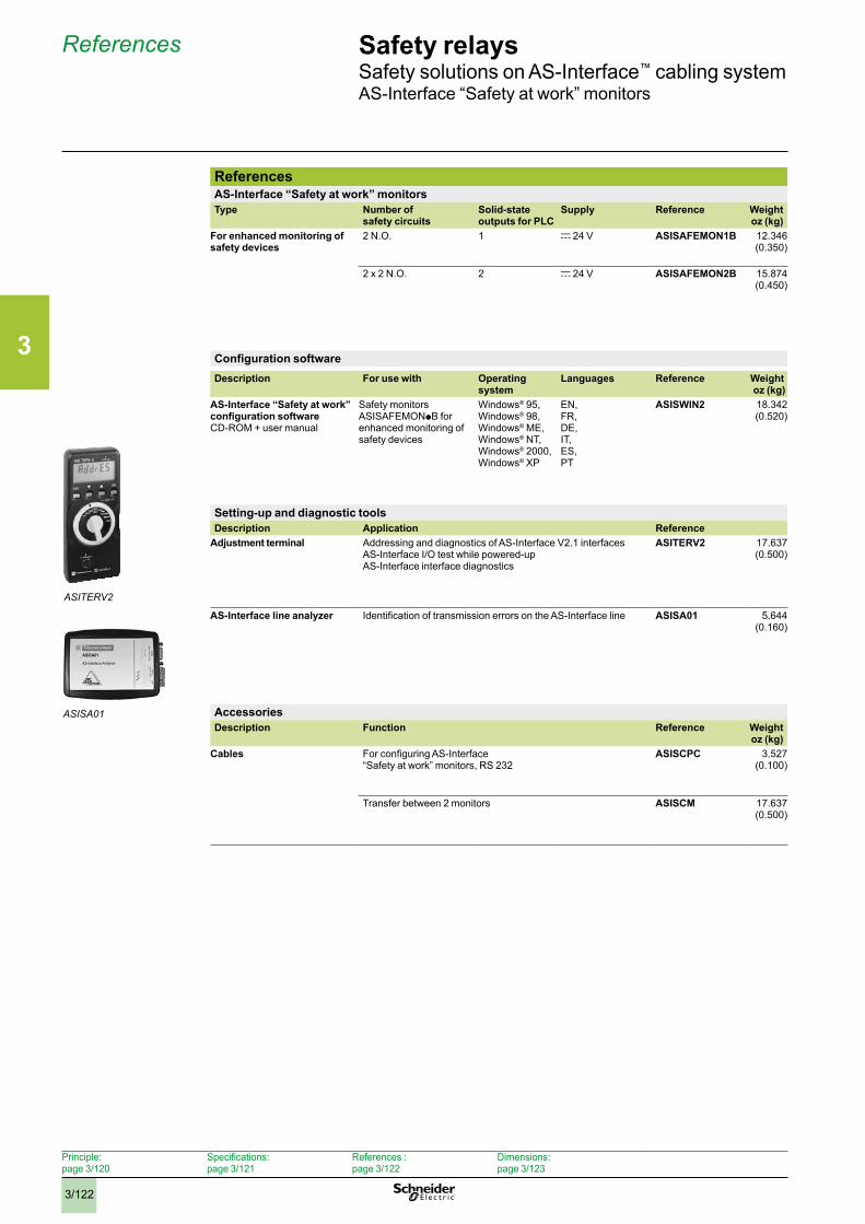
3
3/122
Safety relaysSafety solutions on AS-Interface™ cabling systemAS-Interface “Safety at work” monitors
ReferencesAS-Interface “Safety at work” monitorsType Number of
safety circuitsSolid-state outputs for PLC
Supply Reference Weightoz (kg)
For enhanced monitoring of safety devices
2 N.O. 1
c 24 V ASISAFEMON1B 12.346 (0.350)
2 x 2 N.O. 2
c 24 V ASISAFEMON2B 15.874 (0.450)
Configuration softwareDescription For use with Operating
systemLanguages Reference Weight
oz (kg)AS-Interface “Safety at work”configuration software CD-ROM + user manual
Safety monitors ASISAFEMONpB for enhanced monitoring of safety devices
Windows® 95, Windows® 98, Windows® ME, Windows® NT, Windows® 2000, Windows® XP
EN, FR, DE, IT, ES, PT
ASISWIN2 18.342 (0.520)
Setting-up and diagnostic toolsDescription Application Reference
Adjustment terminal Addressing and diagnostics of AS-Interface V2.1 interfacesAS-Interface I/O test while powered-upAS-Interface interface diagnostics
ASITERV2 17.637 (0.500)
AS-Interface line analyzer Identification of transmission errors on the AS-Interface line
ASISA01 5.644 (0.160)
AccessoriesDescription Function Reference Weight
oz (kg)Cables For configuring AS-Interface
“Safety at work” monitors, RS 232
ASISCPC 3.527 (0.100)
Transfer between 2 monitors
ASISCM 17.637 (0.500)
References
ASITERV2
ASISA01
Principle: page 3/120
Specifications: page 3/121
References : page 3/122
Dimensions: page 3/123
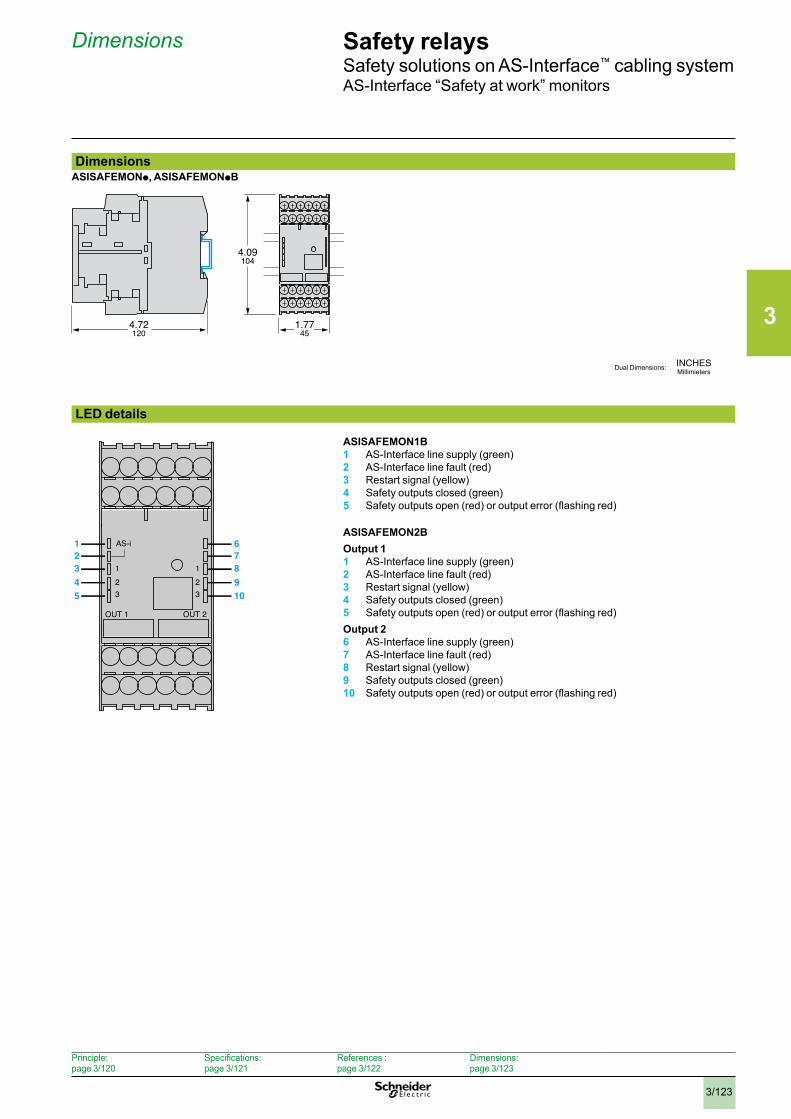
3
3/123
Safety relaysSafety solutions on AS-Interface™ cabling systemAS-Interface “Safety at work” monitors
DimensionsASISAFEMONp, ASISAFEMONpB
LED details
ASISAFEMON2BOutput 11 AS-Interface line supply (green)2 AS-Interface line fault (red)3 Restart signal (yellow)4 Safety outputs closed (green)5 Safety outputs open (red) or output error (flashing red)Output 26 AS-Interface line supply (green)7 AS-Interface line fault (red)8 Restart signal (yellow)9 Safety outputs closed (green)10 Safety outputs open (red) or output error (flashing red)
Dimensions
INCHESMillimietersDual Dimensions:
AS-i
123
OUT 1 OUT 2
123
12345
678910
4.72120
1.7745
4.09104
ASISAFEMON1B1 AS-Interface line supply (green)2 AS-Interface line fault (red)3 Restart signal (yellow)4 Safety outputs closed (green)5 Safety outputs open (red) or output error (flashing red)
Principle: page 3/120
Specifications: page 3/121
References : page 3/122
Dimensions: page 3/123
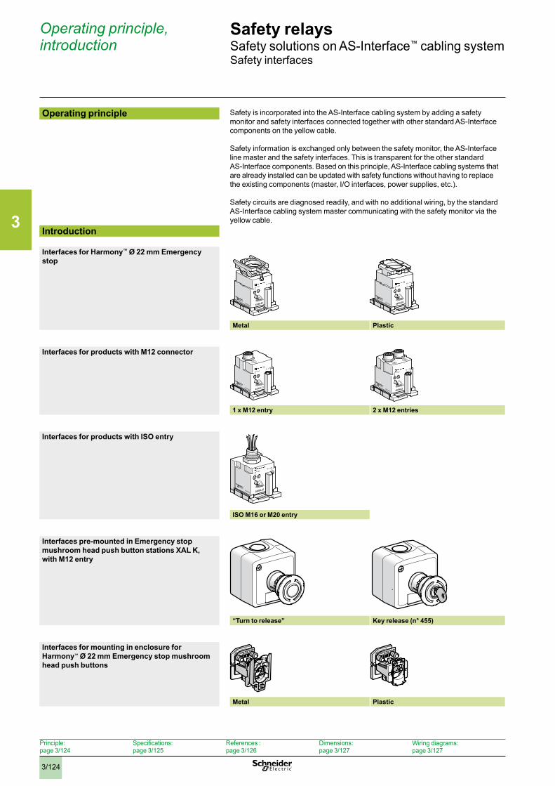
3
3/124
Safety relaysSafety solutions on AS-Interface™ cabling systemSafety interfaces
Operating principle, introduction
Operating principle Safety is incorporated into the AS-Interface cabling system by adding a safety monitor and safety interfaces connected together with other standard AS-Interface components on the yellow cable.
Safety information is exchanged only between the safety monitor, the AS-Interface line master and the safety interfaces. This is transparent for the other standard AS-Interface components. Based on this principle, AS-Interface cabling systems that are already installed can be updated with safety functions without having to replace the existing components (master, I/O interfaces, power supplies, etc.).
Safety circuits are diagnosed readily, and with no additional wiring, by the standard AS-Interface cabling system master communicating with the safety monitor via the yellow cable.
Introduction
Interfaces for Harmony™ Ø 22 mm Emergency stop
Metal Plastic
Interfaces for products with M12 connector
1 x M12 entry 2 x M12 entries
Interfaces for products with ISO entry
ISO M16 or M20 entry
Interfaces pre-mounted in Emergency stop mushroom head push button stations XAL K, with M12 entry
“Turn to release” Key release (n° 455)
Interfaces for mounting in enclosure for Harmony™ Ø 22 mm Emergency stop mushroom head push buttons
Metal Plastic
Principle: page 3/124
Specifications: page 3/125
References : page 3/126
Dimensions: page 3/127
Wiring diagrams:page 3/127
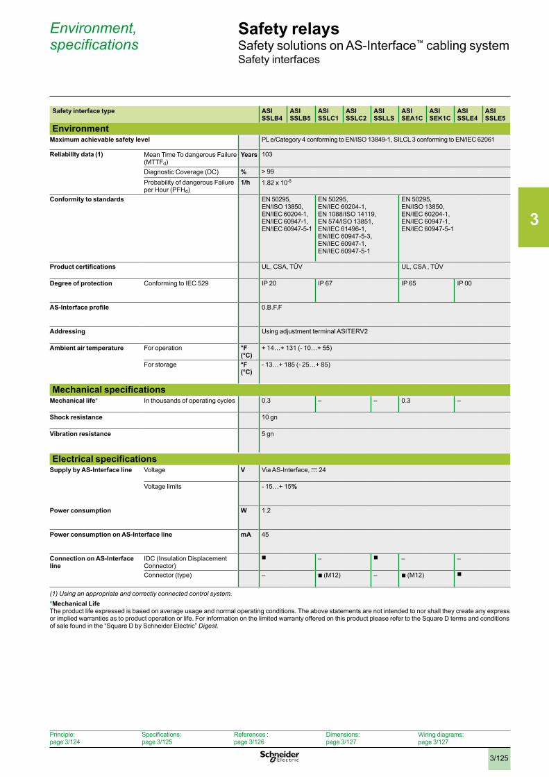
3
3/125
Safety relaysSafety solutions on AS-Interface™ cabling systemSafety interfaces
Environment, specifications
Safety interface type ASISSLB4
ASISSLB5
ASISSLC1
ASISSLC2
ASISSLLS
ASISEA1C
ASISEK1C
ASISSLE4
ASISSLE5
EnvironmentMaximum achievable safety level PL e/Category 4 conforming to EN/ISO 13849-1, SILCL 3 conforming to EN/IEC 62061
Reliability data (1) Mean Time To dangerous Failure (MTTFd)
Years 103
Diagnostic Coverage (DC) % > 99
Probability of dangerous Failure per Hour (PFHd)
1/h 1.82 x 10⁻⁸
Conformity to standards
EN 50295,EN/ISO 13850,EN/IEC 60204-1,EN/IEC 60947-1,EN/IEC 60947-5-1
EN 50295,EN/IEC 60204-1,EN 1088/ISO 14119,EN 574/ISO 13851,EN/IEC 61496-1,EN/IEC 60947-5-3,EN/IEC 60947-1,EN/IEC 60947-5-1
EN 50295,EN/ISO 13850,EN/IEC 60204-1,EN/IEC 60947-1,EN/IEC 60947-5-1
Product certifications UL, CSA, TÜV UL, CSA , TÜV
Degree of protection Conforming to IEC 529
IP 20 IP 67 IP 65 IP 00
AS-Interface profile
0.B.F.F
Addressing Using adjustment terminal ASITERV2
Ambient air temperature For operation °F (°C)
+ 14…+ 131 (- 10…+ 55)
For storage °F (°C)
- 13…+ 185 (- 25…+ 85)
Mechanical specificationsMechanical life* In thousands of operating cycles 0.3 – – 0.3 –
Shock resistance 10 gn
Vibration resistance
5 gn
Electrical specificationsSupply by AS-Interface line Voltage V Via AS-Interface, c 24
Voltage limits
- 15…+ 15%
Power consumption W
1.2
Power consumption on AS-Interface line mA
45
Connection on AS-Interface line
IDC (Insulation Displacement Connector)
b – b – –
Connector (type) – b (M12) – b (M12) b
(1) Using an appropriate and correctly connected control system .*Mechanical LifeThe product life expressed is based on average usage and normal operating conditions. The above statements are not intended to nor shall they create any express or implied warranties as to product operation or life. For information on the limited warranty offered on this product please refer to the Square D terms and conditions of sale found in the “Square D by Schneider Electric” Digest.
Principle: page 3/124
Specifications: page 3/125
References : page 3/126
Dimensions: page 3/127
Wiring diagrams:page 3/127
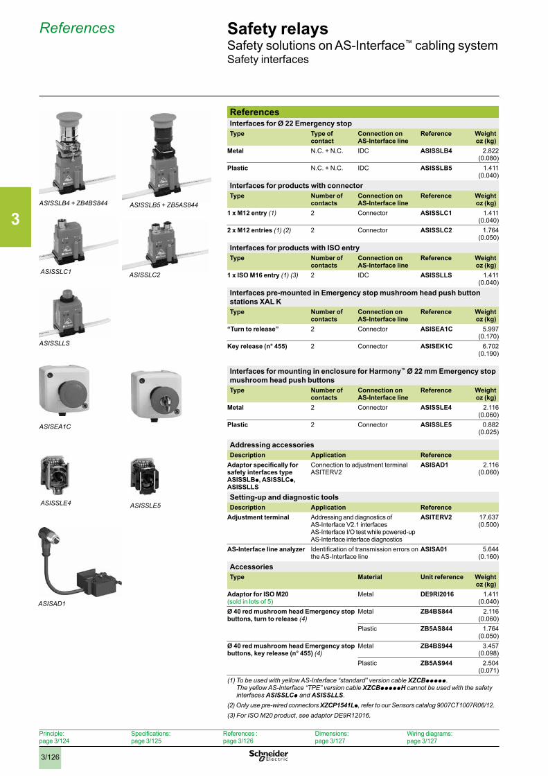
3
3/126
Safety relaysSafety solutions on AS-Interface™ cabling systemSafety interfaces
References
ReferencesInterfaces for Ø 22 Emergency stopType Type of
contactConnection on AS-Interface line
Reference Weightoz (kg)
Metal N.C. + N.C. IDC ASISSLB4 2.822 (0.080)
Plastic N.C. + N.C. IDC ASISSLB5 1.411 (0.040)
Interfaces for products with connectorType Number of
contactsConnection on AS-Interface line
Reference Weightoz (kg)
1 x M12 entry (1) 2 Connector ASISSLC1 1.411 (0.040)
2 x M12 entries (1) (2) 2 Connector ASISSLC2 1.764 (0.050)
Interfaces for products with ISO entryType Number of
contactsConnection on AS-Interface line
Reference Weightoz (kg)
1 x ISO M16 entry (1) (3) 2 IDC ASISSLLS 1.411 (0.040)
Interfaces pre-mounted in Emergency stop mushroom head push button stations XAL KType Number of
contactsConnection on AS-Interface line
Reference Weightoz (kg)
“Turn to release” 2 Connector ASISEA1C 5.997 (0.170)
Key release (n° 455) 2 Connector ASISEK1C 6.702(0.190)
Interfaces for mounting in enclosure for Harmony™ Ø 22 mm Emergency stop mushroom head push buttonsType Number of
contactsConnection on AS-Interface line
Reference Weightoz (kg)
Metal 2 Connector ASISSLE4 2.116 (0.060)
Plastic 2 Connector ASISSLE5 0.882 (0.025)
Addressing accessoriesDescription Application Reference
Adaptor specifically for safety interfaces type ASISSLBp, ASISSLCp, ASISSLLS
Connection to adjustment terminal ASITERV2
ASISAD1 2.116 (0.060)
Setting-up and diagnostic toolsDescription Application Reference
Adjustment terminal Addressing and diagnostics of AS-Interface V2.1 interfacesAS-Interface I/O test while powered-upAS-Interface interface diagnostics
ASITERV2 17.637(0.500)
AS-Interface line analyzer Identification of transmission errors on the AS-Interface line
ASISA01 5.644(0.160)
AccessoriesType Material Unit reference Weight
oz (kg)Adaptor for ISO M20 (sold in lots of 5)
Metal DE9RI2016 1.411 (0.040)
Ø 40 red mushroom head Emergency stop buttons, turn to release (4)
Metal ZB4BS844 2.116 (0.060)
Plastic ZB5AS844 1.764 (0.050)
Ø 40 red mushroom head Emergency stop buttons, key release (n° 455) (4)
Metal ZB4BS944 3.457(0.098)
Plastic ZB5AS944 2.504(0.071)
(1) To be used with yellow AS-Interface “standard” version cable XZCBppppp . The yellow AS-Interface “TPE” version cable XZCBpppppH cannot be used with the safety interfaces ASISSLCp and ASISSLLS .
(2) Only use pre-wired connectors XZCP1541Lp, refer to our Sensors catalog 9007CT1007R06/12 .(3) For ISO M20 product, see adaptor DE9R12016 .
ASISSLB5 + ZB5AS844ASISSLB4 + ZB4BS844
ASISSLC1 ASISSLC2
ASISSLLS
ASISEA1C
ASISSLE5ASISSLE4
ASISAD1
Principle: page 3/124
Specifications: page 3/125
References : page 3/126
Dimensions: page 3/127
Wiring diagrams:page 3/127
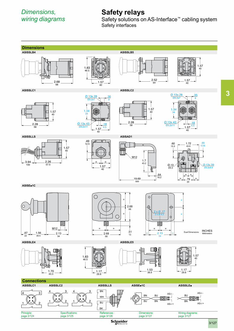
3
3/127
Safety relaysSafety solutions on AS-Interface™ cabling systemSafety interfaces
Dimensions, wiring diagrams
DimensionsASISSLB4 ASISSLB5
ASISSLC1 ASISSLC2
ASISSLLS ASISAD1
ASISEp1C
ASISSLE4 ASISSLE5
ConnectionsASISSLC1 ASISSLC2 ASISSLLS ASISEp1C ASISSLEp
INCHESMillimietersDual Dimensions:
2.6868
1.5740
1.8346.5
2.5264
1.5740
1.5740
.359
Ø.13x.28Ø3.2x7
Ø.13x.43Ø3.2x11
.184.5
1.5740
1.5740
2.2858
1.3434
.4912.5
= =
1.5740
1.5740
3.94100
2.2657.5
.6416.2
M12
= =
.6015.3
= =
Ø.13x.39Ø3.3x9.9
Ø.13Ø3.3
.5513.95
1.743.2
19.69500
.7920
1.7243.6
1.5740
1.5740
1.3434
2.2858
.359
Ø.13x.28Ø3.2x7
Ø.13x.43Ø3,2x11
.184.5
1.7043.3
1.8346.5
1.1729.8
1.5338.9
1.1729.8
1.5740
4 3
1 2
4 3
1 2
4 3
1 2
BN
WH
BU
BK
BU
BN
BN
BU2 4
1
3
AS-i -
AS-i +
BU
BN
AS-i -
AS-i +
Principle: page 3/124
Specifications: page 3/125
References : page 3/126
Dimensions: page 3/127
Wiring diagrams:page 3/127
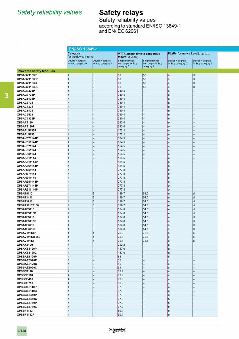
3
3/128
Safety relaysSafety reliability valuesaccording to standard EN/ISO 13849-1 and EN/IEC 62061
Safety reliability values
EN/ISO 13849-1 EN/IEC 62061 (EN/IEC 61508) Category for the device internal
MTTFd (mean time to dangerous failure. in years)
PL (Performance Level): up to... DC (diagnostic capability) for the device internal
PFHd (Dangerous Failure per Hour) SILCL (Safety Integrity Level Claim Level) HFT (Hardware Fault Tolerance)
Device + outputs in Stop category 0
Device + outputs in Stop category 1
Single channel with output in Stop category 0
Single channel with output in Stop category 1
Device + outputs in Stop category 0
Device + outputs in Stop category 1
Device + outputs in Stop category 0
Device + outputs in Stop category 1
Device + outputs in Stop category 0
Device + outputs in Stop category 1
Device + outputs in Stop category 0
Device + outputs in Stop category 1
Preventa safety ModulesXPSABV1133P 4 3 53 53 e d > 99 % 60…90 % 3.00 x 10⁻⁸ 2.00 x 10⁻⁷ 3 2 1XPSABV11330P 4 3 53 53 e d > 99 % 60…90 % 3.00 x 10⁻⁸ 2.00 x 10⁻⁷ 3 2 1XPSABV1133C 4 3 53 53 e d > 99 % 60…90 % 3.00 x 10⁻⁸ 2.00 x 10⁻⁷ 3 2 1XPSABV11330C 4 3 53 53 e d > 99 % 60…90 % 3.00 x 10⁻⁸ 2.00 x 10⁻⁷ 3 2 1XPSAC3421P 4 – 210.4 – e – > 99 % – 3.56 x 10⁻⁹ – 3 – 1 XPSAC3721P 4 – 210.4 – e – > 99 % – 3.56 x 10⁻⁹ – 3 – 1 XPSAC5121P 4 – 210.4 – e – > 99 % – 3.56 x 10⁻⁹ – 3 – 1 XPSAC3721 4 – 210.4 – e – > 99 % – 3.56 x 10⁻⁹ – 3 – 1 XPSAC1321 4 – 210.4 – e – > 99 % – 3.56 x 10⁻⁹ – 3 – 1 XPSAC5121 4 – 210.4 – e – > 99 % – 3.56 x 10⁻⁹ – 3 – 1 XPSAC3421 4 – 210.4 – e – > 99 % – 3.56 x 10⁻⁹ – 3 – 1 XPSAC1321P 4 – 210.4 – e – > 99 % – 3.56 x 10⁻⁹ – 3 – 1 XPSAF5130 4 – 243.0 – e – > 99 % – 4.62 x 10⁻⁹ – 3 – 1 XPSAF5130P 4 – 243.0 – e – > 99 % – 4.62 x 10⁻⁹ – 3 – 1 XPSAFL5130P 4 – 172.1 – e – > 99 % – 5.61 x 10⁻⁹ – 3 – 1 XPSAFL5130 4 – 172.1 – e – > 99 % – 5.61 x 10⁻⁹ – 3 – 1 XPSAK371144P 4 – 154.5 – e – > 99 % – 7.39 x 10⁻⁹ – 3 – 1 XPSAK351144P 4 – 154.5 – e – > 99 % – 7.39 x 10⁻⁹ – 3 – 1 XPSAK371144 4 – 154.5 – e – > 99 % – 7.39 x 10⁻⁹ – 3 – 1 XPSAK351144 4 – 154.5 – e – > 99 % – 7.39 x 10⁻⁹ – 3 – 1 XPSAK361144 4 – 154.5 – e – > 99 % – 7.39 x 10⁻⁹ – 3 – 1 XPSAK311144 4 – 154.5 – e – > 99 % – 7.39 x 10⁻⁹ – 3 – 1 XPSAK311144P 4 – 154.5 – e – > 99 % – 7.39 x 10⁻⁹ – 3 – 1 XPSAK361144P 4 – 154.5 – e – > 99 % – 7.39 x 10⁻⁹ – 3 – 1 XPSAR351144 4 – 277.8 – e – > 99 % – 2.22 x 10⁻⁹ – 3 – 1 XPSAR371144 4 – 277.8 – e – > 99 % – 2.22 x 10⁻⁹ – 3 – 1 XPSAR311144 4 – 277.8 – e – > 99 % – 2.22 x 10⁻⁹ – 3 – 1 XPSAR351144P 4 – 277.8 – e – > 99 % – 2.22 x 10⁻⁹ – 3 – 1 XPSAR371144P 4 – 277.8 – e – > 99 % – 2.22 x 10⁻⁹ – 3 – 1 XPSAR311144P 4 – 277.8 – e – > 99 % – 2.22 x 10⁻⁹ – 3 – 1 XPSAT5110 4 3 139.7 54.0 e d > 99 % 96.9 % 6.84 x 10⁻⁹ 2.05 x 10⁻⁸ 3 2 1 XPSAT3410 4 3 139.7 54.0 e d > 99 % 96.9 % 6.84 x 10⁻⁹ 2.05 x 10⁻⁸ 3 2 1 XPSAT3710 4 3 139.7 54.0 e d > 99 % 96.9 % 6.84 x 10⁻⁹ 2.05 x 10⁻⁸ 3 2 1 XPSAT5110T100 4 3 139.7 54.0 e d > 99 % 96.9 % 6.84 x 10⁻⁹ 2.05 x 10⁻⁸ 3 2 1 XPSATE5110 4 3 134.8 54.5 e d > 99 % 98.4 % 6.81 x 10⁻⁹ 1.96 x 10⁻⁸ 3 2 1 XPSATE5110P 4 3 134.8 54.5 e d > 99 % 98.4 % 6.81 x 10⁻⁹ 1.96 x 10⁻⁸ 3 2 1 XPSATE3410 4 3 134.8 54.5 e d > 99 % 98.4 % 6.81 x 10⁻⁹ 1.96 x 10⁻⁸ 3 2 1 XPSATE3410P 4 3 134.8 54.5 e d > 99 % 98.4 % 6.81 x 10⁻⁹ 1.96 x 10⁻⁸ 3 2 1 XPSATE3710 4 3 134.8 54.5 e d > 99 % 98.4 % 6.81 x 10⁻⁹ 1.96 x 10⁻⁸ 3 2 1 XPSATE3710P 4 3 134.8 54.5 e d > 99 % 98.4 % 6.81 x 10⁻⁹ 1.96 x 10⁻⁸ 3 2 1 XPSAV11113P 4 4 75.8 75.8 e e > 99 % > 99 % 7.95 x 10⁻⁹ 7.95 x 10⁻⁹ 3 3 1 XPSAV11113T050 4 4 75.8 75.8 e e > 99 % > 99 % 7.95 x 10⁻⁹ 7.95 x 10⁻⁹ 3 3 1 XPSAV11113 4 4 75.8 75.8 e e > 99 % > 99 % 7.95 x 10⁻⁹ 7.95 x 10⁻⁹ 3 3 1 XPSAX5120 4 – 222.2 – e – > 99 % – 1.90 x 10⁻⁹ – 3 – 1 XPSAXE5120P 4 – 457.0 – e – > 99 % – 3.00 x 10⁻⁸ – 3 – 1 XPSAXE5120C 4 – 457.0 – e – > 99 % – 3.00 x 10⁻⁸ – 3 – 1 XPSBAE5120P 1 – 55 – c – – – 2.1 x 10⁻⁶ – 1 – 0 XPSBAE3920P 1 – 55 – c – – – 2.1 x 10⁻⁶ – 1 – 0 XPSBAE5120C 1 – 55 – c – – – 2.1 x 10⁻⁶ – 1 – 0 XPSBAE3920C 1 – 55 – c – – – 2.1 x 10⁻⁶ – 1 – 0 XPSBC1110 4 – 63.9 – e – > 99 % – 1.75 x 10⁻⁸ – 3 – 1 XPSBC3110 4 – 63.9 – e – > 99 % – 1.75 x 10⁻⁸ – 3 – 1 XPSBC3410 4 – 63.9 – e – > 99 % – 1.75 x 10⁻⁸ – 3 – 1 XPSBC3710 4 – 63.9 – e – > 99 % – 1.75 x 10⁻⁸ – 3 – 1 XPSBCE3110P 4 – 37.0 – e – > 99 % – 3.00 x 10⁻⁸ – 3 – 1 XPSBCE3110C 4 – 37.0 – e – > 99 % – 3.00 x 10⁻⁸ – 3 – 1 XPSBCE3410P 4 – 37.0 – e – > 99 % – 3.00 x 10⁻⁸ – 3 – 1 XPSBCE3410C 4 – 37.0 – e – > 99 % – 3.00 x 10⁻⁸ – 3 – 1 XPSBCE3710P 4 – 37.0 – e – > 99 % – 3.00 x 10⁻⁸ – 3 – 1 XPSBCE3710C 4 – 37.0 – e – > 99 % – 3.00 x 10⁻⁸ – 3 – 1 XPSBF1132 4 – 50.1 – e – > 99 % – 1.30 x 10⁻⁸ – 3 – 1 XPSBF1132P 4 – 50.1 – e – > 99 % – 1.30 x 10⁻⁸ – 3 – 1
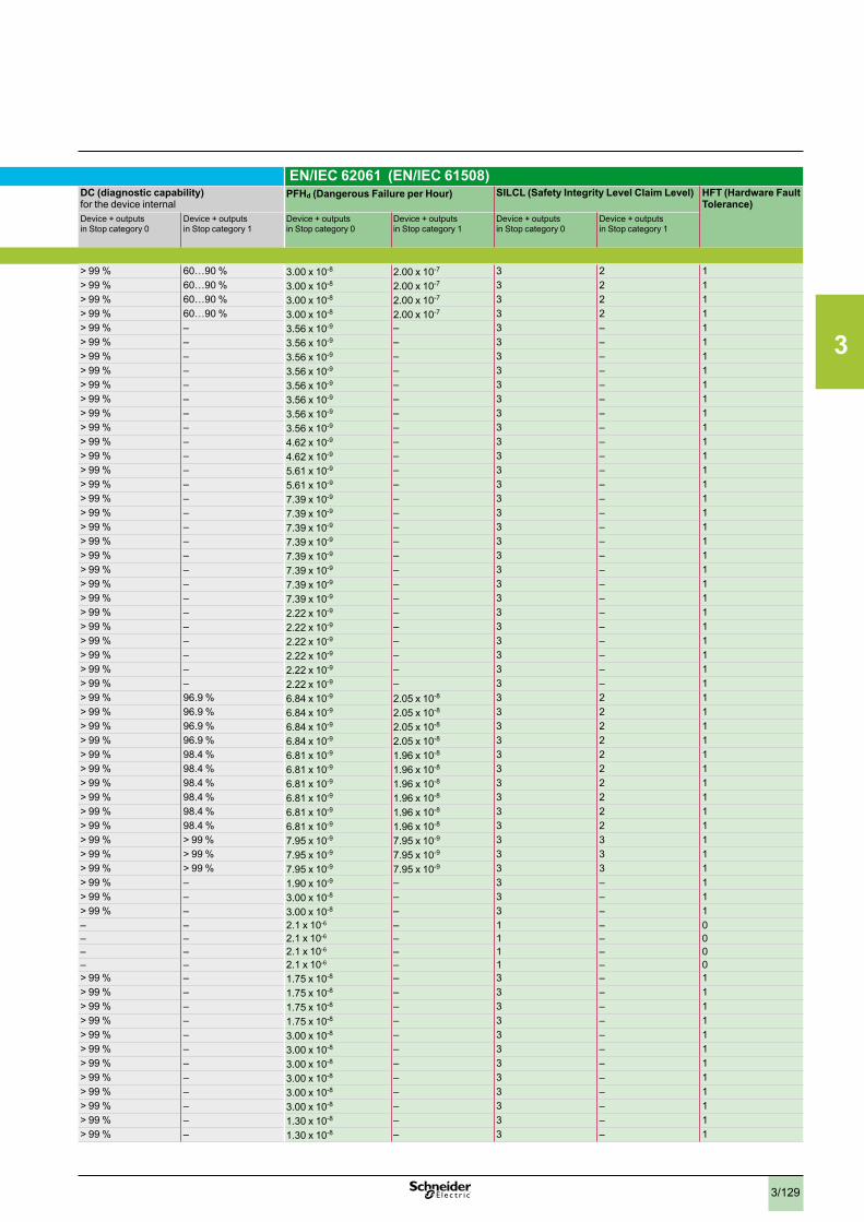
3
3/129
EN/ISO 13849-1 EN/IEC 62061 (EN/IEC 61508) Category for the device internal
MTTFd (mean time to dangerous failure. in years)
PL (Performance Level): up to... DC (diagnostic capability) for the device internal
PFHd (Dangerous Failure per Hour) SILCL (Safety Integrity Level Claim Level) HFT (Hardware Fault Tolerance)
Device + outputs in Stop category 0
Device + outputs in Stop category 1
Single channel with output in Stop category 0
Single channel with output in Stop category 1
Device + outputs in Stop category 0
Device + outputs in Stop category 1
Device + outputs in Stop category 0
Device + outputs in Stop category 1
Device + outputs in Stop category 0
Device + outputs in Stop category 1
Device + outputs in Stop category 0
Device + outputs in Stop category 1
Preventa safety ModulesXPSABV1133P 4 3 53 53 e d > 99 % 60…90 % 3.00 x 10⁻⁸ 2.00 x 10⁻⁷ 3 2 1XPSABV11330P 4 3 53 53 e d > 99 % 60…90 % 3.00 x 10⁻⁸ 2.00 x 10⁻⁷ 3 2 1XPSABV1133C 4 3 53 53 e d > 99 % 60…90 % 3.00 x 10⁻⁸ 2.00 x 10⁻⁷ 3 2 1XPSABV11330C 4 3 53 53 e d > 99 % 60…90 % 3.00 x 10⁻⁸ 2.00 x 10⁻⁷ 3 2 1XPSAC3421P 4 – 210.4 – e – > 99 % – 3.56 x 10⁻⁹ – 3 – 1 XPSAC3721P 4 – 210.4 – e – > 99 % – 3.56 x 10⁻⁹ – 3 – 1 XPSAC5121P 4 – 210.4 – e – > 99 % – 3.56 x 10⁻⁹ – 3 – 1 XPSAC3721 4 – 210.4 – e – > 99 % – 3.56 x 10⁻⁹ – 3 – 1 XPSAC1321 4 – 210.4 – e – > 99 % – 3.56 x 10⁻⁹ – 3 – 1 XPSAC5121 4 – 210.4 – e – > 99 % – 3.56 x 10⁻⁹ – 3 – 1 XPSAC3421 4 – 210.4 – e – > 99 % – 3.56 x 10⁻⁹ – 3 – 1 XPSAC1321P 4 – 210.4 – e – > 99 % – 3.56 x 10⁻⁹ – 3 – 1 XPSAF5130 4 – 243.0 – e – > 99 % – 4.62 x 10⁻⁹ – 3 – 1 XPSAF5130P 4 – 243.0 – e – > 99 % – 4.62 x 10⁻⁹ – 3 – 1 XPSAFL5130P 4 – 172.1 – e – > 99 % – 5.61 x 10⁻⁹ – 3 – 1 XPSAFL5130 4 – 172.1 – e – > 99 % – 5.61 x 10⁻⁹ – 3 – 1 XPSAK371144P 4 – 154.5 – e – > 99 % – 7.39 x 10⁻⁹ – 3 – 1 XPSAK351144P 4 – 154.5 – e – > 99 % – 7.39 x 10⁻⁹ – 3 – 1 XPSAK371144 4 – 154.5 – e – > 99 % – 7.39 x 10⁻⁹ – 3 – 1 XPSAK351144 4 – 154.5 – e – > 99 % – 7.39 x 10⁻⁹ – 3 – 1 XPSAK361144 4 – 154.5 – e – > 99 % – 7.39 x 10⁻⁹ – 3 – 1 XPSAK311144 4 – 154.5 – e – > 99 % – 7.39 x 10⁻⁹ – 3 – 1 XPSAK311144P 4 – 154.5 – e – > 99 % – 7.39 x 10⁻⁹ – 3 – 1 XPSAK361144P 4 – 154.5 – e – > 99 % – 7.39 x 10⁻⁹ – 3 – 1 XPSAR351144 4 – 277.8 – e – > 99 % – 2.22 x 10⁻⁹ – 3 – 1 XPSAR371144 4 – 277.8 – e – > 99 % – 2.22 x 10⁻⁹ – 3 – 1 XPSAR311144 4 – 277.8 – e – > 99 % – 2.22 x 10⁻⁹ – 3 – 1 XPSAR351144P 4 – 277.8 – e – > 99 % – 2.22 x 10⁻⁹ – 3 – 1 XPSAR371144P 4 – 277.8 – e – > 99 % – 2.22 x 10⁻⁹ – 3 – 1 XPSAR311144P 4 – 277.8 – e – > 99 % – 2.22 x 10⁻⁹ – 3 – 1 XPSAT5110 4 3 139.7 54.0 e d > 99 % 96.9 % 6.84 x 10⁻⁹ 2.05 x 10⁻⁸ 3 2 1 XPSAT3410 4 3 139.7 54.0 e d > 99 % 96.9 % 6.84 x 10⁻⁹ 2.05 x 10⁻⁸ 3 2 1 XPSAT3710 4 3 139.7 54.0 e d > 99 % 96.9 % 6.84 x 10⁻⁹ 2.05 x 10⁻⁸ 3 2 1 XPSAT5110T100 4 3 139.7 54.0 e d > 99 % 96.9 % 6.84 x 10⁻⁹ 2.05 x 10⁻⁸ 3 2 1 XPSATE5110 4 3 134.8 54.5 e d > 99 % 98.4 % 6.81 x 10⁻⁹ 1.96 x 10⁻⁸ 3 2 1 XPSATE5110P 4 3 134.8 54.5 e d > 99 % 98.4 % 6.81 x 10⁻⁹ 1.96 x 10⁻⁸ 3 2 1 XPSATE3410 4 3 134.8 54.5 e d > 99 % 98.4 % 6.81 x 10⁻⁹ 1.96 x 10⁻⁸ 3 2 1 XPSATE3410P 4 3 134.8 54.5 e d > 99 % 98.4 % 6.81 x 10⁻⁹ 1.96 x 10⁻⁸ 3 2 1 XPSATE3710 4 3 134.8 54.5 e d > 99 % 98.4 % 6.81 x 10⁻⁹ 1.96 x 10⁻⁸ 3 2 1 XPSATE3710P 4 3 134.8 54.5 e d > 99 % 98.4 % 6.81 x 10⁻⁹ 1.96 x 10⁻⁸ 3 2 1 XPSAV11113P 4 4 75.8 75.8 e e > 99 % > 99 % 7.95 x 10⁻⁹ 7.95 x 10⁻⁹ 3 3 1 XPSAV11113T050 4 4 75.8 75.8 e e > 99 % > 99 % 7.95 x 10⁻⁹ 7.95 x 10⁻⁹ 3 3 1 XPSAV11113 4 4 75.8 75.8 e e > 99 % > 99 % 7.95 x 10⁻⁹ 7.95 x 10⁻⁹ 3 3 1 XPSAX5120 4 – 222.2 – e – > 99 % – 1.90 x 10⁻⁹ – 3 – 1 XPSAXE5120P 4 – 457.0 – e – > 99 % – 3.00 x 10⁻⁸ – 3 – 1 XPSAXE5120C 4 – 457.0 – e – > 99 % – 3.00 x 10⁻⁸ – 3 – 1 XPSBAE5120P 1 – 55 – c – – – 2.1 x 10⁻⁶ – 1 – 0 XPSBAE3920P 1 – 55 – c – – – 2.1 x 10⁻⁶ – 1 – 0 XPSBAE5120C 1 – 55 – c – – – 2.1 x 10⁻⁶ – 1 – 0 XPSBAE3920C 1 – 55 – c – – – 2.1 x 10⁻⁶ – 1 – 0 XPSBC1110 4 – 63.9 – e – > 99 % – 1.75 x 10⁻⁸ – 3 – 1 XPSBC3110 4 – 63.9 – e – > 99 % – 1.75 x 10⁻⁸ – 3 – 1 XPSBC3410 4 – 63.9 – e – > 99 % – 1.75 x 10⁻⁸ – 3 – 1 XPSBC3710 4 – 63.9 – e – > 99 % – 1.75 x 10⁻⁸ – 3 – 1 XPSBCE3110P 4 – 37.0 – e – > 99 % – 3.00 x 10⁻⁸ – 3 – 1 XPSBCE3110C 4 – 37.0 – e – > 99 % – 3.00 x 10⁻⁸ – 3 – 1 XPSBCE3410P 4 – 37.0 – e – > 99 % – 3.00 x 10⁻⁸ – 3 – 1 XPSBCE3410C 4 – 37.0 – e – > 99 % – 3.00 x 10⁻⁸ – 3 – 1 XPSBCE3710P 4 – 37.0 – e – > 99 % – 3.00 x 10⁻⁸ – 3 – 1 XPSBCE3710C 4 – 37.0 – e – > 99 % – 3.00 x 10⁻⁸ – 3 – 1 XPSBF1132 4 – 50.1 – e – > 99 % – 1.30 x 10⁻⁸ – 3 – 1 XPSBF1132P 4 – 50.1 – e – > 99 % – 1.30 x 10⁻⁸ – 3 – 1
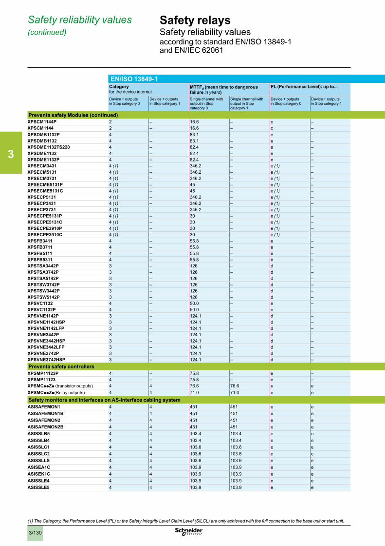
3
3/130
(1) The Category, the Performance Level (PL) or the Safety Integrity Level Claim Level (SILCL) are only achieved with the full connection to the base unit or start unit .
EN/ISO 13849-1 EN/IEC 62061 (EN/IEC 61508) Category for the device internal
MTTFd (mean time to dangerous failure in years)
PL (Performance Level): up to... DC (diagnostic capability) for the device internal
PFHd (Dangerous Failure per Hour) SILCL (Safety Integrity Level Claim Level) HFT (Hardware Fault Tolerance)
Device + outputs in Stop category 0
Device + outputs in Stop category 1
Single channel with output in Stop category 0
Single channel with output in Stop category 1
Device + outputs in Stop category 0
Device + outputs in Stop category 1
Device + outputs in Stop category 0
Device + outputs in Stop category 1
Device + outputs in Stop category 0
Device + outputs in Stop category 1
Device + outputs in Stop category 0
Device + outputs in Stop category 1
Preventa safety Modules (continued)XPSCM1144P 2 – 16.6 – c – 95.5 % – 3.12 x 10⁻⁷ – 1 – 1XPSCM1144 2 – 16.6 – c – 95.5 % – 3.12 x 10⁻⁷ – 1 – 1XPSDMB1132P 4 – 83.1 – e – > 99 % – 3.92 x 10⁻⁹ – 3 – 1 XPSDMB1132 4 – 83.1 – e – > 99 % – 3.92 x 10⁻⁹ – 3 – 1 XPSDME1132TS220 4 – 82.4 – e – > 99 % – 3.97 x 10⁻⁹ – 3 – 1 XPSDME1132 4 – 82.4 – e – > 99 % – 3.97 x 10⁻⁹ – 3 – 1 XPSDME1132P 4 – 82.4 – e – > 99 % – 3.97 x 10⁻⁹ – 3 – 1 XPSECM3431 4 (1) – 346.2 – e (1) – 0…99 % (1) – 7.51 x 10⁻⁹ – 3 (1) – 1 XPSECM5131 4 (1) – 346.2 – e (1) – 0…99 % (1) – 7.51 x 10⁻⁹ – 3 (1) – 1 XPSECM3731 4 (1) – 346.2 – e (1) – 0…99 % (1) – 7.51 x 10⁻⁹ – 3 (1) – 1 XPSECME5131P 4 (1) – 45 – e (1) – 60…90 % – 2.00 x 10⁻⁷ – 3 (1) – 1XPSECME5131C 4 (1) – 45 – e (1) – 60…90 % – 2.00 x 10⁻⁷ – 3 (1) – 1XPSECP5131 4 (1) – 346.2 – e (1) – 0…99 % (1) – 7.51 x 10⁻⁹ – 3 (1) – 1 XPSECP3431 4 (1) – 346.2 – e (1) – 0…99 % (1) – 7.51 x 10⁻⁹ – 3 (1) – 1 XPSECP3731 4 (1) – 346.2 – e (1) – 0…99 % (1) – 7.51 x 10⁻⁹ – 3 (1) – 1 XPSECPE5131P 4 (1) – 30 – e (1) – 0…99 % (1) – 3.00 x 10⁻⁹ – 3 (1) – 1XPSECPE5131C 4 (1) – 30 – e (1) – 0…99 % (1) – 3.00 x 10⁻⁹ – 3 (1) – 1 XPSECPE3910P 4 (1) – 30 – e (1) – 0…99 % (1) – 3.00 x 10⁻⁹ – 3 (1) – 1 XPSECPE3910C 4 (1) – 30 – e (1) – 0…99 % (1) – 3.00 x 10⁻⁹ – 3 (1) – 1 XPSFB3411 4 – 55.8 – e – > 99 % – 1.13 x 10⁻⁸ – 3 – 1 XPSFB3711 4 – 55.8 – e – > 99 % – 1.13 x 10⁻⁸ – 3 – 1 XPSFB5111 4 – 55.8 – e – > 99 % – 1.13 x 10⁻⁸ – 3 – 1 XPSFB5311 4 – 55.8 – e – > 99 % – 1.13 x 10⁻⁸ – 3 – 1 XPSTSA3442P 3 – 126 – d – 60…90 % – 1.30 x 10⁻⁷ – 2 – 1 XPSTSA3742P 3 – 126 – d – 60…90 % – 1.30 x 10⁻⁷ – 2 – 1 XPSTSA5142P 3 – 126 – d – 60…90 % – 1.30 x 10⁻⁷ – 2 – 1 XPSTSW3742P 3 – 126 – d – 60…90 % – 1.30 x 10⁻⁷ – 2 – 1 XPSTSW3442P 3 – 126 – d – 60…90 % – 1.30 x 10⁻⁷ – 2 – 1 XPSTSW5142P 3 – 126 – d – 60…90 % – 1.30 x 10⁻⁷ – 2 – 1 XPSVC1132 4 – 50.0 – e – > 99 % – 1.30 x 10⁻⁸ – 3 – 1 XPSVC1132P 4 – 50.0 – e – > 99 % – 1.30 x 10⁻⁸ – 3 – 1 XPSVNE1142P 3 – 124.1 – d – > 99 % – 9.26 x 10⁻⁹ – 2 – 1 XPSVNE1142HSP 3 – 124.1 – d – > 99 % – 9.26 x 10⁻⁹ – 2 – 1 XPSVNE1142LFP 3 – 124.1 – d – > 99 % – 9.26 x 10⁻⁹ – 2 – 1 XPSVNE3442P 3 – 124.1 – d – > 99 % – 9.26 x 10⁻⁹ – 2 – 1 XPSVNE3442HSP 3 – 124.1 – d – > 99 % – 9.26 x 10⁻⁹ – 2 – 1 XPSVNE3442LFP 3 – 124.1 – d – > 99 % – 9.26 x 10⁻⁹ – 2 – 1 XPSVNE3742P 3 – 124.1 – d – > 99 % – 9.26 x 10⁻⁹ – 2 – 1 XPSVNE3742HSP 3 – 124.1 – d – > 99 % – 9.26 x 10⁻⁹ – 2 – 1 Preventa safety controllersXPSMP11123P 4 – 75.8 – e – > 99 % – 7.95 x 10⁻⁹ – 3 – 1 XPSMP11123 4 – 75.8 – e – > 99 % – 7.95 x 10⁻⁹ – 3 – 1 XPSMCppZp (transistor outputs) 4 4 76.6 76.6 e e > 99 % > 99 % 1.29 x 10⁻⁸ 1.29 x 10⁻⁸ 3 3 1 XPSMCppZp(Relay outputs) 4 4 71.0 71.0 e e > 99 % > 99 % 1.40 x 10⁻⁸ 1.40 x 10⁻⁸ 3 3 1
Safety monitors and interfaces on AS-Interface cabling systemASISAFEMON1 4 4 451 451 e e > 99 % > 99 % 9.00 x 10⁻⁹ 9.00 x 10⁻⁹ 3 3 1 ASISAFEMON1B 4 4 451 451 e e > 99 % > 99 % 9.00 x 10⁻⁹ 9.00 x 10⁻⁹ 3 3 1 ASISAFEMON2 4 4 451 451 e e > 99 % > 99 % 9.00 x 10⁻⁹ 9.00 x 10⁻⁹ 3 3 1 ASISAFEMON2B 4 4 451 451 e e > 99 % > 99 % 9.00 x 10⁻⁹ 9.00 x 10⁻⁹ 3 3 1 ASISSLB5 4 4 103.4 103.4 e e > 99 % > 99 % 1.82 x 10⁻⁸ 1.82 x 10⁻⁸ 3 3 1ASISSLB4 4 4 103.4 103.4 e e > 99 % > 99 % 1.82 x 10⁻⁸ 1.82 x 10⁻⁸ 3 3 1ASISSLC1 4 4 103.6 103.6 e e > 99 % > 99 % 1.82 x 10⁻⁸ 1.82 x 10⁻⁸ 3 3 1ASISSLC2 4 4 103.6 103.6 e e > 99 % > 99 % 1.82 x 10⁻⁸ 1.82 x 10⁻⁸ 3 3 1ASISSLLS 4 4 103.6 103.6 e e > 99 % > 99 % 1.82 x 10⁻⁸ 1.82 x 10⁻⁸ 3 3 1ASISEA1C 4 4 103.9 103.9 e e > 99 % > 99 % 1.82 x 10⁻⁸ 1.82 x 10⁻⁸ 3 3 1ASISEK1C 4 4 103.9 103.9 e e > 99 % > 99 % 1.82 x 10⁻⁸ 1.82 x 10⁻⁸ 3 3 1ASISSLE4 4 4 103.9 103.9 e e > 99 % > 99 % 1.82 x 10⁻⁸ 1.82 x 10⁻⁸ 3 3 1ASISSLE5 4 4 103.9 103.9 e e > 99 % > 99 % 1.82 x 10⁻⁸ 1.82 x 10⁻⁸ 3 3 1
Safety relaysSafety reliability valuesaccording to standard EN/ISO 13849-1 and EN/IEC 62061
Safety reliability values (continued)
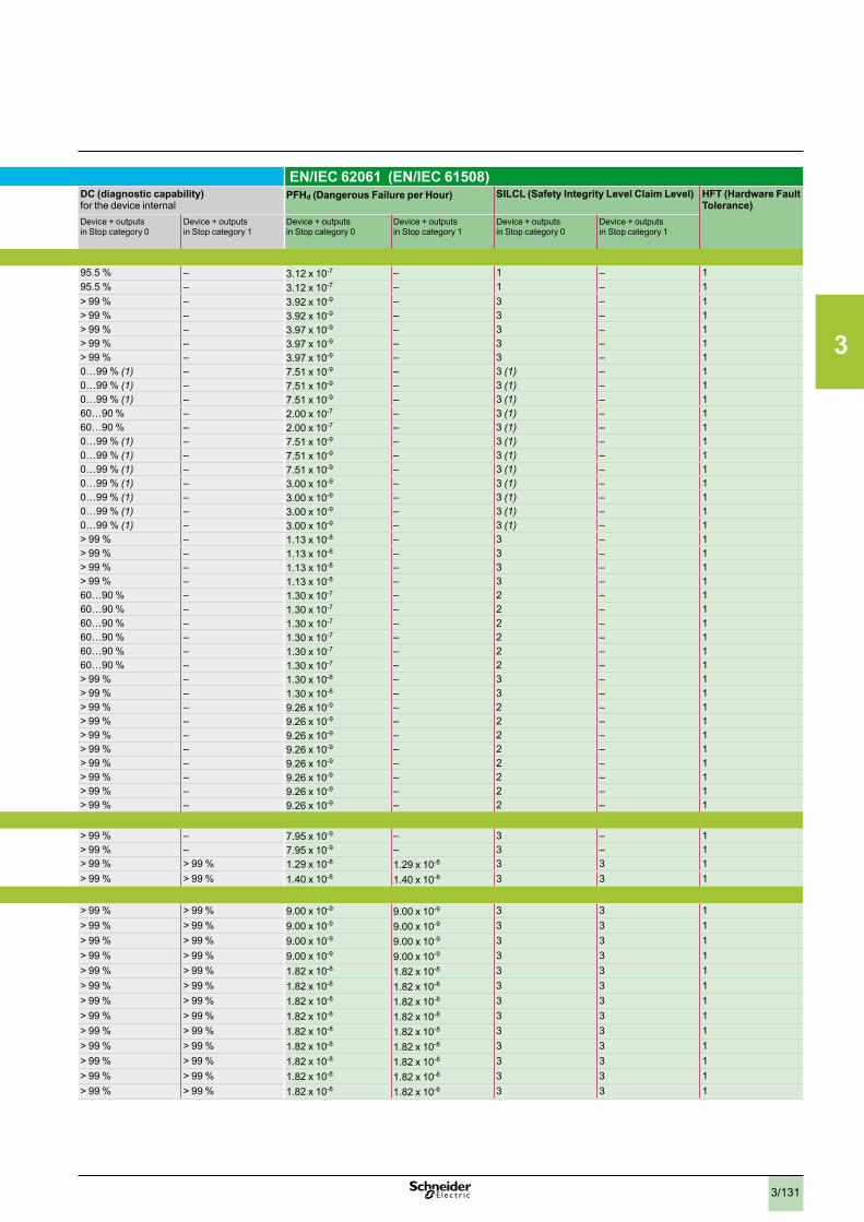
3
3/131
EN/ISO 13849-1 EN/IEC 62061 (EN/IEC 61508) Category for the device internal
MTTFd (mean time to dangerous failure in years)
PL (Performance Level): up to... DC (diagnostic capability) for the device internal
PFHd (Dangerous Failure per Hour) SILCL (Safety Integrity Level Claim Level) HFT (Hardware Fault Tolerance)
Device + outputs in Stop category 0
Device + outputs in Stop category 1
Single channel with output in Stop category 0
Single channel with output in Stop category 1
Device + outputs in Stop category 0
Device + outputs in Stop category 1
Device + outputs in Stop category 0
Device + outputs in Stop category 1
Device + outputs in Stop category 0
Device + outputs in Stop category 1
Device + outputs in Stop category 0
Device + outputs in Stop category 1
Preventa safety Modules (continued)XPSCM1144P 2 – 16.6 – c – 95.5 % – 3.12 x 10⁻⁷ – 1 – 1XPSCM1144 2 – 16.6 – c – 95.5 % – 3.12 x 10⁻⁷ – 1 – 1XPSDMB1132P 4 – 83.1 – e – > 99 % – 3.92 x 10⁻⁹ – 3 – 1 XPSDMB1132 4 – 83.1 – e – > 99 % – 3.92 x 10⁻⁹ – 3 – 1 XPSDME1132TS220 4 – 82.4 – e – > 99 % – 3.97 x 10⁻⁹ – 3 – 1 XPSDME1132 4 – 82.4 – e – > 99 % – 3.97 x 10⁻⁹ – 3 – 1 XPSDME1132P 4 – 82.4 – e – > 99 % – 3.97 x 10⁻⁹ – 3 – 1 XPSECM3431 4 (1) – 346.2 – e (1) – 0…99 % (1) – 7.51 x 10⁻⁹ – 3 (1) – 1 XPSECM5131 4 (1) – 346.2 – e (1) – 0…99 % (1) – 7.51 x 10⁻⁹ – 3 (1) – 1 XPSECM3731 4 (1) – 346.2 – e (1) – 0…99 % (1) – 7.51 x 10⁻⁹ – 3 (1) – 1 XPSECME5131P 4 (1) – 45 – e (1) – 60…90 % – 2.00 x 10⁻⁷ – 3 (1) – 1XPSECME5131C 4 (1) – 45 – e (1) – 60…90 % – 2.00 x 10⁻⁷ – 3 (1) – 1XPSECP5131 4 (1) – 346.2 – e (1) – 0…99 % (1) – 7.51 x 10⁻⁹ – 3 (1) – 1 XPSECP3431 4 (1) – 346.2 – e (1) – 0…99 % (1) – 7.51 x 10⁻⁹ – 3 (1) – 1 XPSECP3731 4 (1) – 346.2 – e (1) – 0…99 % (1) – 7.51 x 10⁻⁹ – 3 (1) – 1 XPSECPE5131P 4 (1) – 30 – e (1) – 0…99 % (1) – 3.00 x 10⁻⁹ – 3 (1) – 1XPSECPE5131C 4 (1) – 30 – e (1) – 0…99 % (1) – 3.00 x 10⁻⁹ – 3 (1) – 1 XPSECPE3910P 4 (1) – 30 – e (1) – 0…99 % (1) – 3.00 x 10⁻⁹ – 3 (1) – 1 XPSECPE3910C 4 (1) – 30 – e (1) – 0…99 % (1) – 3.00 x 10⁻⁹ – 3 (1) – 1 XPSFB3411 4 – 55.8 – e – > 99 % – 1.13 x 10⁻⁸ – 3 – 1 XPSFB3711 4 – 55.8 – e – > 99 % – 1.13 x 10⁻⁸ – 3 – 1 XPSFB5111 4 – 55.8 – e – > 99 % – 1.13 x 10⁻⁸ – 3 – 1 XPSFB5311 4 – 55.8 – e – > 99 % – 1.13 x 10⁻⁸ – 3 – 1 XPSTSA3442P 3 – 126 – d – 60…90 % – 1.30 x 10⁻⁷ – 2 – 1 XPSTSA3742P 3 – 126 – d – 60…90 % – 1.30 x 10⁻⁷ – 2 – 1 XPSTSA5142P 3 – 126 – d – 60…90 % – 1.30 x 10⁻⁷ – 2 – 1 XPSTSW3742P 3 – 126 – d – 60…90 % – 1.30 x 10⁻⁷ – 2 – 1 XPSTSW3442P 3 – 126 – d – 60…90 % – 1.30 x 10⁻⁷ – 2 – 1 XPSTSW5142P 3 – 126 – d – 60…90 % – 1.30 x 10⁻⁷ – 2 – 1 XPSVC1132 4 – 50.0 – e – > 99 % – 1.30 x 10⁻⁸ – 3 – 1 XPSVC1132P 4 – 50.0 – e – > 99 % – 1.30 x 10⁻⁸ – 3 – 1 XPSVNE1142P 3 – 124.1 – d – > 99 % – 9.26 x 10⁻⁹ – 2 – 1 XPSVNE1142HSP 3 – 124.1 – d – > 99 % – 9.26 x 10⁻⁹ – 2 – 1 XPSVNE1142LFP 3 – 124.1 – d – > 99 % – 9.26 x 10⁻⁹ – 2 – 1 XPSVNE3442P 3 – 124.1 – d – > 99 % – 9.26 x 10⁻⁹ – 2 – 1 XPSVNE3442HSP 3 – 124.1 – d – > 99 % – 9.26 x 10⁻⁹ – 2 – 1 XPSVNE3442LFP 3 – 124.1 – d – > 99 % – 9.26 x 10⁻⁹ – 2 – 1 XPSVNE3742P 3 – 124.1 – d – > 99 % – 9.26 x 10⁻⁹ – 2 – 1 XPSVNE3742HSP 3 – 124.1 – d – > 99 % – 9.26 x 10⁻⁹ – 2 – 1 Preventa safety controllersXPSMP11123P 4 – 75.8 – e – > 99 % – 7.95 x 10⁻⁹ – 3 – 1 XPSMP11123 4 – 75.8 – e – > 99 % – 7.95 x 10⁻⁹ – 3 – 1 XPSMCppZp (transistor outputs) 4 4 76.6 76.6 e e > 99 % > 99 % 1.29 x 10⁻⁸ 1.29 x 10⁻⁸ 3 3 1 XPSMCppZp(Relay outputs) 4 4 71.0 71.0 e e > 99 % > 99 % 1.40 x 10⁻⁸ 1.40 x 10⁻⁸ 3 3 1
Safety monitors and interfaces on AS-Interface cabling systemASISAFEMON1 4 4 451 451 e e > 99 % > 99 % 9.00 x 10⁻⁹ 9.00 x 10⁻⁹ 3 3 1 ASISAFEMON1B 4 4 451 451 e e > 99 % > 99 % 9.00 x 10⁻⁹ 9.00 x 10⁻⁹ 3 3 1 ASISAFEMON2 4 4 451 451 e e > 99 % > 99 % 9.00 x 10⁻⁹ 9.00 x 10⁻⁹ 3 3 1 ASISAFEMON2B 4 4 451 451 e e > 99 % > 99 % 9.00 x 10⁻⁹ 9.00 x 10⁻⁹ 3 3 1 ASISSLB5 4 4 103.4 103.4 e e > 99 % > 99 % 1.82 x 10⁻⁸ 1.82 x 10⁻⁸ 3 3 1ASISSLB4 4 4 103.4 103.4 e e > 99 % > 99 % 1.82 x 10⁻⁸ 1.82 x 10⁻⁸ 3 3 1ASISSLC1 4 4 103.6 103.6 e e > 99 % > 99 % 1.82 x 10⁻⁸ 1.82 x 10⁻⁸ 3 3 1ASISSLC2 4 4 103.6 103.6 e e > 99 % > 99 % 1.82 x 10⁻⁸ 1.82 x 10⁻⁸ 3 3 1ASISSLLS 4 4 103.6 103.6 e e > 99 % > 99 % 1.82 x 10⁻⁸ 1.82 x 10⁻⁸ 3 3 1ASISEA1C 4 4 103.9 103.9 e e > 99 % > 99 % 1.82 x 10⁻⁸ 1.82 x 10⁻⁸ 3 3 1ASISEK1C 4 4 103.9 103.9 e e > 99 % > 99 % 1.82 x 10⁻⁸ 1.82 x 10⁻⁸ 3 3 1ASISSLE4 4 4 103.9 103.9 e e > 99 % > 99 % 1.82 x 10⁻⁸ 1.82 x 10⁻⁸ 3 3 1ASISSLE5 4 4 103.9 103.9 e e > 99 % > 99 % 1.82 x 10⁻⁸ 1.82 x 10⁻⁸ 3 3 1
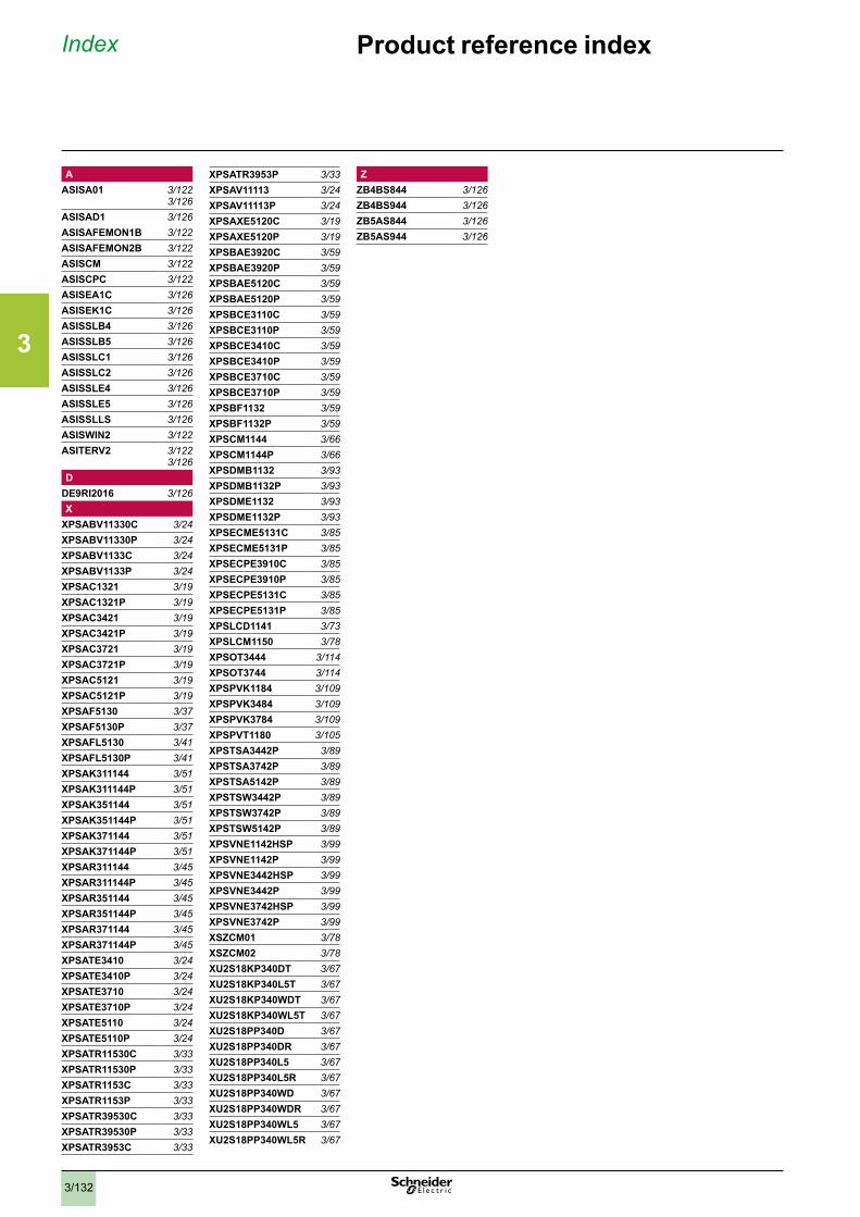
3
3/132
Index Product reference index
AASISA01 3/122
3/126ASISAD1 3/126ASISAFEMON1B 3/122ASISAFEMON2B 3/122ASISCM 3/122ASISCPC 3/122ASISEA1C 3/126ASISEK1C 3/126ASISSLB4 3/126ASISSLB5 3/126ASISSLC1 3/126ASISSLC2 3/126ASISSLE4 3/126ASISSLE5 3/126ASISSLLS 3/126ASISWIN2 3/122ASITERV2 3/122
3/126D
DE9RI2016 3/126X
XPSABV11330C 3/24XPSABV11330P 3/24XPSABV1133C 3/24XPSABV1133P 3/24XPSAC1321 3/19XPSAC1321P 3/19XPSAC3421 3/19XPSAC3421P 3/19XPSAC3721 3/19XPSAC3721P 3/19XPSAC5121 3/19XPSAC5121P 3/19XPSAF5130 3/37XPSAF5130P 3/37XPSAFL5130 3/41XPSAFL5130P 3/41XPSAK311144 3/51XPSAK311144P 3/51XPSAK351144 3/51XPSAK351144P 3/51XPSAK371144 3/51XPSAK371144P 3/51XPSAR311144 3/45XPSAR311144P 3/45XPSAR351144 3/45XPSAR351144P 3/45XPSAR371144 3/45XPSAR371144P 3/45XPSATE3410 3/24XPSATE3410P 3/24XPSATE3710 3/24XPSATE3710P 3/24XPSATE5110 3/24XPSATE5110P 3/24XPSATR11530C 3/33XPSATR11530P 3/33XPSATR1153C 3/33XPSATR1153P 3/33XPSATR39530C 3/33XPSATR39530P 3/33XPSATR3953C 3/33
XPSATR3953P 3/33XPSAV11113 3/24XPSAV11113P 3/24XPSAXE5120C 3/19XPSAXE5120P 3/19XPSBAE3920C 3/59XPSBAE3920P 3/59XPSBAE5120C 3/59XPSBAE5120P 3/59XPSBCE3110C 3/59XPSBCE3110P 3/59XPSBCE3410C 3/59XPSBCE3410P 3/59XPSBCE3710C 3/59XPSBCE3710P 3/59XPSBF1132 3/59XPSBF1132P 3/59XPSCM1144 3/66XPSCM1144P 3/66XPSDMB1132 3/93XPSDMB1132P 3/93XPSDME1132 3/93XPSDME1132P 3/93XPSECME5131C 3/85XPSECME5131P 3/85XPSECPE3910C 3/85XPSECPE3910P 3/85XPSECPE5131C 3/85XPSECPE5131P 3/85XPSLCD1141 3/73XPSLCM1150 3/78XPSOT3444 3/114XPSOT3744 3/114XPSPVK1184 3/109XPSPVK3484 3/109XPSPVK3784 3/109XPSPVT1180 3/105XPSTSA3442P 3/89XPSTSA3742P 3/89XPSTSA5142P 3/89XPSTSW3442P 3/89XPSTSW3742P 3/89XPSTSW5142P 3/89XPSVNE1142HSP 3/99XPSVNE1142P 3/99XPSVNE3442HSP 3/99XPSVNE3442P 3/99XPSVNE3742HSP 3/99XPSVNE3742P 3/99XSZCM01 3/78XSZCM02 3/78XU2S18KP340DT 3/67XU2S18KP340L5T 3/67XU2S18KP340WDT 3/67XU2S18KP340WL5T 3/67XU2S18PP340D 3/67XU2S18PP340DR 3/67XU2S18PP340L5 3/67XU2S18PP340L5R 3/67XU2S18PP340WD 3/67XU2S18PP340WDR 3/67XU2S18PP340WL5 3/67XU2S18PP340WL5R 3/67
ZZB4BS844 3/126ZB4BS944 3/126ZB5AS844 3/126ZB5AS944 3/126


Schneider Electric USA, Inc.8001 Knightdale Blvd. Knightdale, NC 27545
USA Customer Care CenterTel: 888-778-2733
Schneider Electric Canada5985 McLaughlin Rd.Missassauga, Ontario, Canada L5R 1B8
Canada Customer Care CenterTel: 800-565-6699
© 2009–2013 Schneider Electric. All rights reserved. Schneider Electric, Advantys, AS-Interface, Harmony, Magelis, Modbus, Momentum, Phaseo, Premium, Preventa, Transparent Ready, and “Make the most of your energy” are trademarks owned by Schneider Electric Industries SAS or its affiliated companies. All other trademarks are property of their respective owners.
Design: Schneider ElectricPhotos: Schneider Electric
MKTED208051EN-US Rev. 01, Chapter 312/2013
www.schneider-electric.com