Embed Size (px)
Citation preview

International Journal of Electrical and Computer Engineering (IJECE)
Vol. 10, No. 6, December 2020, pp. 6139~6152
ISSN: 2088-8708, DOI: 10.11591/ijece.v10i6.pp6139-6152 6139
Journal homepage: http://ijece.iaescore.com/index.php/IJECE
Sliding mode performance control applied to a DFIG system for
a wind energy production
Mansouri Fatima Zohra, Bendjebbar Mokhtar, Mazari Benyounes Laboratory of Development of Electrical Drives (LDEE),
University of Sciences and Technology Mohamed Boudiaf, Algeria
Article Info ABSTRACT
Article history:
Received Jun 29, 2019
Revised May 28, 2020
Accepted Jun 9, 2020
This project presents a strategy of field control then sliding mode control put
in to the conversion process of wind energy containing an asynchronous
generator with double fed (DFAG; DFIG). A model was developed for each
component of the wind turbine (turbine, DFAG and cascade rectifier-
inverter). MPPT device must be introduced in order to obtain maximum
energy efficiency so that PI-MPPT method is made. The objective is to apply
this command to control independently the active and reactive powers
generated by the asynchronous generator uncoupled by orientation from
the flow. The results of digital simulations obtained show the improvement of
the performances of the sliding control compared to the field control, also it
has provided information on the commands available techniques as reference
tracking and robustness.
Keywords:
Doubly fed induction generator
MPPT
PI controller
Sliding mode control
Wind energy conversion system
Copyright © 2020 Institute of Advanced Engineering and Science.
All rights reserved.
Corresponding Author:
Mansouri Fatima Zohra,
Department of Electrical Engineering, Laboratory of Development of Electrical Drives (LDEE),
University of Science and Technology of Oran Mohamed Boudiaf El Mnaouar,
BP 1505, Bir El Djir 3100, Oran, Algeria.
Email: [email protected]
1. INTRODUCTION
Wind energy is one of the rapid growth renewable energy in the world. This energy is inexhaustible,
clean and do not create greenhouse gases [1, 2]. Conventional techniques were used to adjust the wind,
but assuming the wind operation in balanced conditions [3]. Advances in technology of wind led to
the design of a more powerful drive to improve their behaviors and make it more robust and reliable [4].
The generation of electrical energy by means of double-fed asynchronous machine is one of the current areas
of research, using driving means such as wind power incorporated into a wind energy system, the function
can DFIG on wide range of wind speed and get the maximum possible power for each wind speed [5].
In this article we demonstrate the modeling, the simulation and the comparison of the wind turbine
driven doubly-fed induction generator performances of using at the same time the command of the PI control
and sliding mode control [6, 7]. A strategy for controlling the sliding mode has been put in place to control
two powers and also achieve maximum wind energy [8, 9]. The results of simulation show that this strategy
has rapid dynamic response also a good robustness and low dependence parameters on the model [10].
2. MODELING AND CONTROL OF THE WIND TURBINE
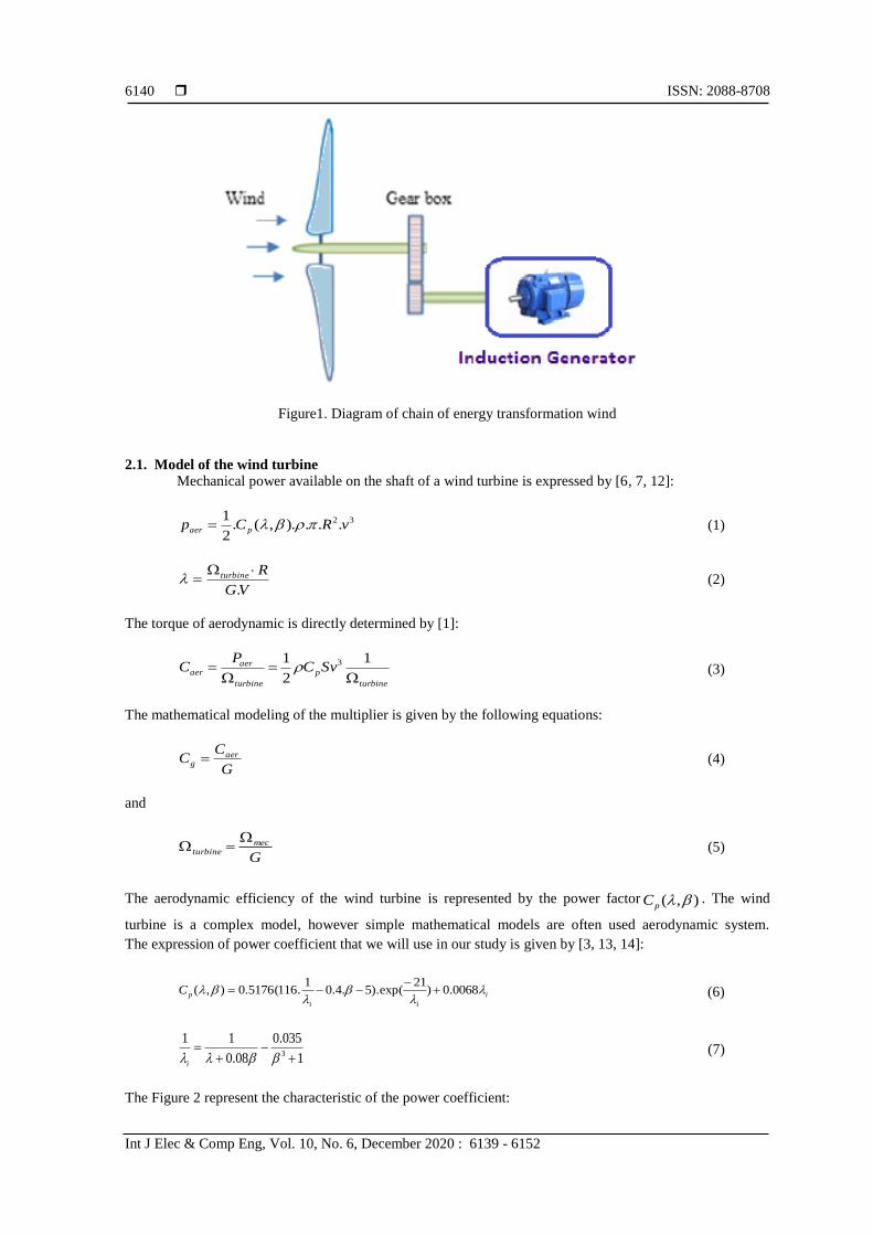
The device, which is studied here, consists of a wind turbine including of the blades length R
actuating a generator through a speed-increasing gear of profit G. Figure 1 describes a chain of conversion of
wind energy [5, 11].
ISSN: 2088-8708
Int J Elec & Comp Eng, Vol. 10, No. 6, December 2020 : 6139 - 6152
6140
Figure1. Diagram of chain of energy transformation wind
2.1. Model of the wind turbine
Mechanical power available on the shaft of a wind turbine is expressed by [6, 7, 12]:
32...).,(.2
1vRCp paer (1)
VG
Rturbine
.
(2)
The torque of aerodynamic is directly determined by [1]:
turbine
p
turbine
aeraer SvC
PC
1
2
1 3 (3)
The mathematical modeling of the multiplier is given by the following equations:
G
CC aer
g (4)
and
G
mecturbine
(5)
The aerodynamic efficiency of the wind turbine is represented by the power factor ),( pC . The wind
turbine is a complex model, however simple mathematical models are often used aerodynamic system.
The expression of power coefficient that we will use in our study is given by [3, 13, 14]:
i
ii
pC
0068.0)21
exp().5.4.01
.116(5176.0),(
(6)
1
035.0
08.0
113
i
(7)
The Figure 2 represent the characteristic of the power coefficient:

Int J Elec & Comp Eng ISSN: 2088-8708
Sliding mode performance control applied to… (Mansouri Fatima Zohra)
6141
Figure 2. The characteristic of the power coefficient
We determine the evolution of the mechanical speed by the fundamental equation of dynamics [6]:
dt
dJC mec
mec
(8)
visemgmec CCCC (9)
mecvis fC . (10)
gturbine JG
JJ
2 (11)
gturbine fG
ff
2 (12)
The diagram block related to this modeling of the turbine is represented on Figure 3.
Figure 3. Block diagram of the model turbine
ISSN: 2088-8708
Int J Elec & Comp Eng, Vol. 10, No. 6, December 2020 : 6139 - 6152
6142
2.2. Control of the wind turbine
An electromagnetic torque control strategy adjusting to the mechanical speed to be presented in this part
in order to maximize the electrical power generated [15-18]. This principle is known as terminology (MPPT).
We are interested in controlling the electromagnetic torque servo mechanical speed using a conventional PI
controller [19]. For this study, we assume that the electric machine and its drive are ideal and therefore,
the electromagnetic torque develops at all times equal to its reference value, regardless of the power
generated. For this study, we assume that the electric machine and its drive are ideal and therefore,
the electromagnetic torque develops at all times equal to its reference value, regardless of the power
generated. The maximum power extraction techniques include determining the speed of the turbine, which
provides maximum power generated [17, 18].
)..(1
mecemgmec fCC
Jdt
d
(13)
The structure of control consists in regulating the couple appearing on the turbine shaft so as to fix its speed
at a reference. Therefore, we obtain the following relation [5]:
)()/( mecrefemref pKiKpC (14)
)( refturbineref G (15)
R
VCp
refturbine
.. max
(16)
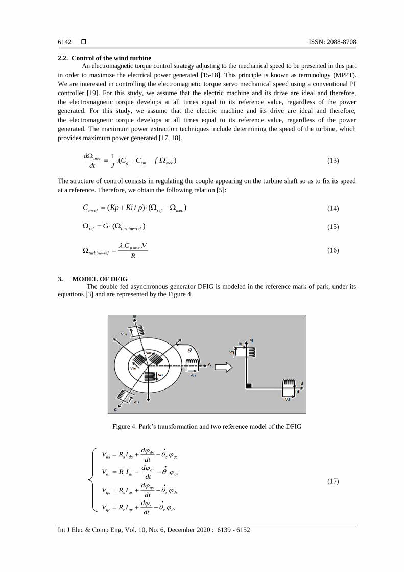
3. MODEL OF DFIG
The double fed asynchronous generator DFIG is modeled in the reference mark of park, under its
equations [3] and are represented by the Figure 4.
Figure 4. Park’s transformation and two reference model of the DFIG
qssds
dssdsdt
dIRV
qrrdr
drrdrdt
dIRV
dss
qs
qssqsdt
dIRV
drrr
qrrqrdt
dIRV
(17)

Int J Elec & Comp Eng ISSN: 2088-8708
Sliding mode performance control applied to… (Mansouri Fatima Zohra)
6143
drdssds MIIL
qrqssqs MIIL
dsqrrdr MIIL
qsqrrqr MIIL
(18)
dt
djfCC rem
(19)
Electromagnetic torque is expressed in terms of currents and flux:
)( drqsqrds
s
em IIL
MPC
(20)
3.1. Power control
By putting the equations which connect the values, we can easily control the production of the wind
and also realize an independent control of the active and reactive power [20]. A referential d-q; related to
the rotating field and a stator flow aligned on the axis were adopted, For obvious reasons of simplification.
Therefore:
sds ,
0qs (21)
The flow equations (19) are becoming:
drdssds MIIL (22)
qrqss MIIL 0 (23)
Based on a few considerations, we obtain:
0dsV ,sqs VV et
s
ss
V
(24)
s
sdr
s
dsL
IL
MI
(25)
qr
s
qs IL
MI (26)
In the biphasic landmark, statoric powers of DFIG are written:
qsqsdsdss IVIVP (27)
qsdsdsqss IVIVQ (28)
The adaptation of these equations gives simplifying assumptions:
qr
s
ss IL
MVP (29)
ss
sdr
s
ssL
VI
L
MVQ
2
(30)

ISSN: 2088-8708
Int J Elec & Comp Eng, Vol. 10, No. 6, December 2020 : 6139 - 6152
6144
For controlling the generator, expressions are set, showing the relationship between current and
rotor voltages which will apply to it.
qrs
s
rdr
s
rdrrdr IL
MLg
dt
dI
L
MLIRV )()(
22
(31)
s
sdrs
s
r
qr
s
rqrrqrL
MVgI
L
MLg
dt
dI
L
MLIRV )()(
22
(32)
)1(2
rs
m
LL
L (33)
It should be noted that the powers and tensions are linked by a transfer function of the first order.
Due to the low value of the slip, it is possible to establish vector control because the influences of
the couplings remain weak and the d and q axes can be ordered separately with their own regulators.
The method used in the power control is to neglect the coupling terms and to set up an independent regulator
in each axis to control the active and reactive power independently. This method is called the direct method
because the power controllers directly control the rotor tensions [2]. The block diagram representation is
shown on the Figure 5.
Figure 5. Control scheme of the system
4. CONTROL ACTIVE AND REACTIVE POWERS
This section as objective to introduce control algorithms based on two regulators PI and Sliding
mode controllers to regulate a statoric powers to a DFIG system for a wind energy production [21-23].
4.1. PI controller design
The Figure 6 shows a closed loop system corrected by a PI regulator with a transfer function.
The gains of the controllers are voluntarily chosen to be symmetrical, in order to preserve the property of
symmetry of the open-loop:
iipiq
PPPpq
KKK
KKK (34)

Int J Elec & Comp Eng ISSN: 2088-8708
Sliding mode performance control applied to… (Mansouri Fatima Zohra)
6145
And the values of A and B are obtained from:
VLB
LLLPRLA
m
msrrs
.
)(2
(35)
The transfer function of the open loop including the regulator is:
)(
)(
.
.)(
2
2
msr
rs
msr
sm
p
p
i
LLL
RLP
LLL
VL
K
P
K
KP
PG
(36)
To cancel the pole, we added a zero at the same location as the pole, (40) gives a pole value.
)( 2
msr
rs
p
i
LLL
RL
K
K
(37)
The transfer function of the open loop becomes:
)(
)(
.
.)(
2
2
msr
rs
msr
sm
p
p
i
LLL
RLP
LLL
VL
K
P
K
KP
PG
(38)
The closed loop is expressed by this function transfer:
PPH
r
1
1)( (39)
sm
mrs
p
rVL
LRL
K
)(.
1 2 (40)
For a response time τr (5%) = 10-3 s the Kp
and Ki expressions were given by (42).
sm
rsipiqi
sm
mrsPPpqp
VL
RLKKK
VL
LRLKKK
..
10
1
.
)(.
10
1
3
2
3
(41)
Figure 6. Equivalent PI control block

ISSN: 2088-8708
Int J Elec & Comp Eng, Vol. 10, No. 6, December 2020 : 6139 - 6152
6146
4.2. Sliding mode control
The sliding Mode Control, is well known for its robustness against internal uncertainties (variations
in machine parameters), and external (disturbance due to load), and phenomena having been omitted in
the modeling, while having a very good response dynamic [24, 25]. In summary, a sliding mode control is
divided into three parts.
4.3. Control active power
The surface of the control of the active power is given by:
sref PPPS )( (42)
The derivative of surface is:
ssref PPPS )( (43)
We replace the expression of the power becomes:
qr
s
ssref IL
MVPPS )( (44)
We draw the expression from the current of the equation of the Vqr tension:
)()( qrrqr
rs
ssref IRVLL
MVPPS
(45)
By replacing the expression of Vqr by Vqreq+Vqr n the command appears clearly in the following equation:
))(()( qrrqrnqreq
rs
ssref IRVVLL
MVPPS
(46)
During the sliding mode and in permanent mode, we have
0qrnV (47)
We extract from the preceding equation the equivalent manipulated variable Vqreq that is written:
qrr
s
rssref
qreq IRMV
LLSPV
)()( (48)
During the mode of convergence, so that the condition 0)()( PSPS that is to say checked one poses:
qrn
rs
s VLL
MVPS
)( (49)
Consequently, the term of commutation is given by:
)(. ssignKVqrn (50)
To check the stability condition of the system, the parameter K must be positive.
4.4. Control of the reactive power
The surface of control of reactive power is:
sref QQQS )( (51)
0)( PS 0)(
PS
Int J Elec & Comp Eng ISSN: 2088-8708
Sliding mode performance control applied to… (Mansouri Fatima Zohra)
6147
The derivative of surface is:
ssref QQQS )( (52)
We replace the expression of the power becomes:
dr
s
ssref IL
MVQQS )( (53)
We draw the expression from the current of the equation of the Vqr tension:
)()( drrdr
rs
ssref IRVLL
MVQQS
(54)
By replacing the expression of Vdr by Vdreq+Vdr n:
))(()( qrrdrndreq
rs
ssref IRVVLL
MVQQS
(55)
In permanent mode, we have:
0)( QS 0)(
QS 0qrnV (56)
We extract from the preceding equation the equivalent manipulated variable Vqreq that is written:
drr
s
rssref
dreq IRMV
LLSQV
)()( (57)
During the mode of convergence, so that the condition 0)()( QSQS that is to say checked one poses:
drn
rs
s VLL
MVQS
)( (58)
Consequently, the term of commutation is given by:
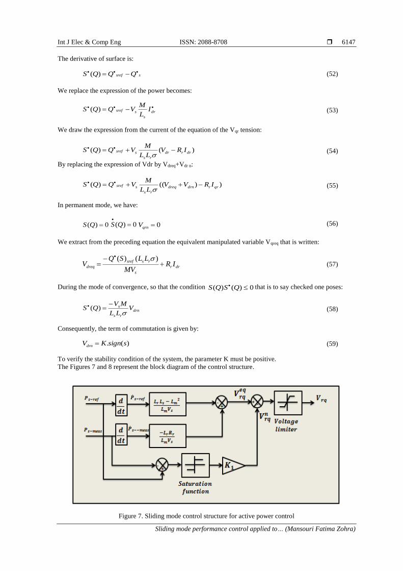
)(. ssignKVdrn (59)
To verify the stability condition of the system, the parameter K must be positive.
The Figures 7 and 8 represent the block diagram of the control structure.
Figure 7. Sliding mode control structure for active power control
ISSN: 2088-8708
Int J Elec & Comp Eng, Vol. 10, No. 6, December 2020 : 6139 - 6152
6148
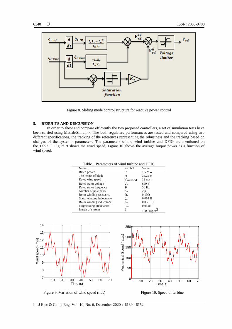
Figure 8. Sliding mode control structure for reactive power control
5. RESULTS AND DISCUSSION
In order to show and compare efficiently the two proposed controllers, a set of simulation tests have
been carried using Matlab/Simulink. The both regulaters performances are tested and compared using two
different specifications, the tracking of the references representing the robustness and the tracking based on
changes of the system’s parameters. The parameters of the wind turbine and DFIG are mentioned on
the Table 1. Figure 9 shows the wind speed, Figure 10 shows the average output power as a function of
wind speed.
Table1. Parameters of wind turbine and DFIG Name Symbol Value
Rated power P 1.5 MW
The length of blade R 35.25 m
Rated wind speed Vwrated 12 m/s
Rated stator voltage Vs 690 V
Rated stator frequency F 50 Hz
Number of pole pairs pn 2 p.u
Rotor winding resistance Rr 0.19Ω
Stator winding inductance Ls 0.084 H
Rotor winding inductance Lr 0.0 213H
Magnetizing inductance Lm 0.051H
Inertia of system J 1000 Kg.m2
Figure 9. Variation of wind speed (m/s)
Figure 10. Speed of turbine
10 20 30 40 50 60 707
8
9
10
11
12
13
14
Time (s)
Win
d s
peed (
m/s
)
0 10 20 30 40 50 60 700
50
100
150
200
250
Time(s)
Mechanic
al S
peed (
rad/s
)

Int J Elec & Comp Eng ISSN: 2088-8708
Sliding mode performance control applied to… (Mansouri Fatima Zohra)
6149
5.1. Reference tracking
Different step inputs for an active and a reactive power were applied and we observed the response
obtained with both PI control and Sliding mode control. Results are presented in the following Figures 11 and 12.
5.2. Robustness
In order to test the robustness of the two controllers, the nominal value of Rr is doubled value, and
the value of mutual inductance Lm is decreased by 10% of its nominal value. Figures 13-16 shows the effect
of parameters variation on the active and reactive power response for the two controllers.
Figure 11. Dynamic responses of PI controller for a step change of active and reactive power
Figure 12. Dynamic responses of sliding mode control for a step change of active and reactive power
Figure 13. Active and reactive power behavior using PI controller with 50% variation of Rr
0 0.5 1 1.5-12000
-10000
-8000
-6000
-4000
-2000
0
Times(s)
Active p
ow
er(
w)
0 0.5 1 1.5-15000
-10000
-5000
0
5000
Times(s)R
eactive p
ow
er(
VA
r)
0 0.5 1 1.5-12000
-10000
-8000
-6000
-4000
-2000
0
Times (s)
Act
ive P
ow
er
(w)
0 0.5 1 1.5-15000
-10000
-5000
0
5000
Times (s)
Reactv
e P
ow
er
(VA
r)
0 0.5 1 1.5-12000
-10000
-8000
-6000
-4000
-2000
0
Times (s)
Active P
ow
er
(w)
0 0.5 1 1.5-15000
-10000
-5000
0
5000
Times(s)
Reactive P
ow
er
(VA
r)

ISSN: 2088-8708
Int J Elec & Comp Eng, Vol. 10, No. 6, December 2020 : 6139 - 6152
6150
Figure 14. Active and reactive power behavior using Sliding Mode control with 50% variation of Rr
Figure 15. Active and reactive power behavior with Lm variation Using PI Controller
Figure 16. Active and reactive power behavior with Lm variation using sliding mode control
5.3. Discussion
With the sliding mode control the results show that the response time is considerably reduced,
a small overshoot and the oscillations are damped more quickly compared to the PI controller. The system in
transient state with the sliding mode is better than the PI control.
0 0.5 1 1.5-12000
-10000
-8000
-6000
-4000
-2000
0
Times (s)
Active P
ow
er
(w)
0 0.5 1 1.5-15000
-10000
-5000
0
5000
Times (s)
Reactv
e P
ow
er
(VA
r)
0 0.5 1 1.5-12000
-10000
-8000
-6000
-4000
-2000
0
Times (s)
Active P
ow
er
(w)
0 0.5 1 1.5-15000
-10000
-5000
0
5000
Times(s)
Reactive P
ow
er
(VA
r)

Int J Elec & Comp Eng ISSN: 2088-8708
Sliding mode performance control applied to… (Mansouri Fatima Zohra)
6151
6. CONCLUSION
This article presented a wind energy conversion system based on the wound rotor induction
generator. Direct vector control of the active and reactive power of the stator was performed using
Matlab/Simulink. The results shown illustrate that mathematical modeling based on knowledge of voltages
and currents can be used to control powers. The comparative study of active and reactive power control
reveals that the PI and Sliding Mode controllers work fairly well under ideal conditions when there is no
disturbance or variation of parameters.
REFERENCES [1] T. Ackermann and L. Soder, “An Overview of Wind Energy-Status 2002,” Renewable and Sustainable Energy
Reviews, vol. 6, no. (1-2), pp. 67-127, 2002.
[2] M. Allam, B. Dehiba, M. Abid, Y. Djeriri, and Redouane Adjoudj, "Etude comparative entre la commande
vectorielle directe et indirecte de la Machine Asynchrone à Double Alimentation (MADA) dédiée à une application
éolienne," Journal of Advanced Research in Science and Technology, vol. 1, no. 2, pp. 88-100, 2014.
[3] B. Wu, Y. Lang, N. Zargari, and S. Kouro, “Power conversion and control of wind energy systems,” John Wiley &
Sons, Inc., United States of America, 2011.
[4] BM. Rapin, J-M. Noël, “Énergie Éolienne,” Dunod, Paris, 2010
[5] F. Poitiers, T. Bouaouiche, M. Machmoum, “Advanced control of a doubly-fed induction generator for wind energy
conversion,” Electric Power Systems Research, vol. 79, no. 7, pp. 1085–1096, 2009.
[6] A. Boyette, “Contrôle-commande d’une GADA avec système de stockage pour la production éolienne,” Thèse de
Doctorat, Université Henry Poincaré, Nancy I, France, 2006.
[7] H-S. Ko, G-G. Yoon, N-H. Kyung, W-P. Hong, “Modeling and control of DFIG-based variable-speed wind-
turbine,” Electric Power Systems Research, vol. 78, no. 11, pp. 1841-1849, 2008.
[8] M. Taoussi, et al., “Comparative study between Backstepping adaptive and Field-oriented control of the DFIG
applied to wind turbines,” International Conference on Advanced Technologies for Signal and Image Processing,
pp. 1-6, 2017.
[9] S-El-M. Ardjoun, M. Abid, A-G. Aissaoui, and A.Naceri, “A robust fuzzy sliding mode control applied to the double fed
induction machine,” International Journal Of Circuits, Systems and signals, vol. 5, no. 4, pp. 315-321, 2011
[10] P. Lopez and A. S. Nouri, “Théorie Elémentaire Et Pratique De La Commande Par Les Régimes Glissants,”
Springer Science & Business Media, vol. 55, 2006.
[11] S. Mensou, A. Essadki, I. Minka, T. Nasser and B. Idrissi, “Backstepping Controller for a Variable Wind Speed
Energy Conversion System Based on a DFIG,” IEEE International Renewable and Sustainable Energy Conference
(IRSEC), pp. 1-6, 2017.
[12] H. Alami, E. Ziani, B. Bossoufi, “Speed control of the doubly fed induction generator applied to a wind system,”
Journal of Theoretical and Applied Information Technology, vol. 83 no. 3, pp. 426-433, 2016.
[13] Hamane, B., Doumbia, M. L., Cheriti, A., Belmokhtar, K., “Comparative Study of PI, RST, Sliding Mode and
Fuzzy Supervisory Controllers for DFIG based Wind Energy Conversion System,” International journal of
renewable energy, vol. 5, no. 4, pp. 1174-1185, 2015
[14] F. Kendouli, K. Nabti, K. Abed, and H. Benalla, “Modélisation, simulation et contrôle d’une turbine éolienne à
vitesse variable basée sur la génératrice asynchrone à double alimentation,” Revue des Energies Renouvelables,
vol. 14, no. 1, pp. 109-120, 2011.
[15] F. Qiang, and T. Nan “A Strategy research on MPPT technique in photovoltaic power generation system,”
TELKOMNIKA Indonesian Journal of Electrical Engineering, vol. 11, no.12, pp. 7627-7633, 2013.
[16] M. Yuhendri, M. Ashari, and MH. Purnomo, “Maximum Output Power Tracking of Wind Turbine Using
Intelligent Control,” TELKOMNIKA Indonesian Journal of Electrical Engineering, vol. 9, no. 2, pp. 217-226, 2011.
[17] D. C. Phan DC and S. Yamamoto, “Maximum Energy Output of a DFIG Wind Turbine Using an Improved MPPT-
Curve Method,” Energies, vol. 8, no. 10, pp. 11718-11736, 2015.
[18] D. Chung Phan and T. Hieu Trinh, “Maximum Power Extraction Method for Doubly-fed Induction Generator Wind
Turbine,” International Journal of Electrical and Computer Engineering (IJECE), vol. 8, no. 2, pp. 711-722, 2018.
[19] M. Nadour, A. Essadki, and T. Nasser, “Comparative Analysis between PI & Backstepping Control Strategies
of DFIG Driven by Wind Turbine,” International Journal of Renewable Energy Research, vol. 7, no 3,
pp. 1307-1316, 2017.
[20] Y. Ihedrane, C. El Bekkali, and B. Bossoufi, “Power Control of DFIG Generators for Wind Turbines Variable
Speed,” International Journal of Power Electronics and Drive Systems, vol. 8, no. 1, pp. 444-453, 2017.
[21] S. Mensou, A. Essadki, T. Nasser, B. B. Idrissi, “An Efficient Nonlinear Backstepping Controller Approach of a
Wind Power Generation System Based on a DFIG,” International Journal of Renewable Energy Research, vol. 7,
no. 4, pp. 1520-1528, 2017.
[22] I. Minka, A. Essadki, S. Mensou, and T. Nasser, “Power Control of a DFIG Driving by Wind Turbine: Comparison
Study Between ADRC and PI Controller,” International Renewable and Sustainable Energy Conference (IRSEC),
pp. 1-8, 2017.
[23] J. J. Slotine, “Adaptive Sliding controller synthesis for nonlinear systems,” International Journal of Control,
vol. 43, no. 6, pp 1631-1651, 1986.

ISSN: 2088-8708
Int J Elec & Comp Eng, Vol. 10, No. 6, December 2020 : 6139 - 6152
6152
[24] Ardjoun S, Abid M, Aissaoui A, and Tahour A., "A Robust Sliding Mode Control Applied To The Double Fed
Induction Machine," Istanbul University-Journal of Electrical & Electronics Engineering, vol. 12, no. 1,
pp. 1445-1451, 2012.
[25] G. Zoubir, B. Cheikh, A. Tayeb and B. belkacem, “Speed-Sensorless DFIG Wind Turbine for Power Optimization
Using Fuzzy Sliding Mode Observer,” International journal of renewable energy research, vol. 7, no. 2,
pp. 613-621, 2017.
BIOGRAPHIES OF AUTHORS
Mansouri Fatima Zohra was born in Oran, Algeria on March 09, 1989. She received
the Engineer degree in Industriel Automated Systems from the University of Sciences and
Technology of Oran M.B in 2011. She is member of laboratory development electrical drive
(LDEE). Her research interests Renewable Energy, Sliding and Fuzzy Control.
Mokhtar Bendjebbar was born on August, 16, 1965 in Relizane Algeria. He received received
the B.S degree in electrical engineering and the M.S. and PhD degrees in electrical and control
systems from the University of Sciences and Technology of Oran M.B., Algeria, in 1989, 1993,
and 2007, respectively. He is currently Professor of Electrical Engineering at the University of
Sciences and Technology of Oran. His research interests include Electrical machines and Drives
Control, Power Electronics, as well as Intelligent Control and Diagnosis.
Mazari Benyounes (1953) received the state engineer degree in Electrical Engineering in 1978
from the University of Sciences and Technology of Oran (USTO) Algeria, the M.S. degree from
the University of Colorado Boulder U.S.A. in 1981 and the doctorat degree from the Institut
National Polytechnique de Lorraine (INPL) Nancy France in 1992. Since 1982, he was at
the USTO-Oran and from 1987-1992 he was on leave as a researcher at INPL (France). Since
1992 he was a Professor of Electrical Sciences at the same university. His area of research
includes power electronics, traction drives, and harmonics in power systems.