Embed Size (px)
Citation preview
CHALMERS Chalmers University of Technology
Applied Mechanics
Very Large Eddy Simulation of Draft TubeFlow
Walter Gyllenram and Hakan Nilsson
Division of Fluid DynamicsDepartment of Applied MechanicsChalmers University of Technology
Goteborg, Sweden
CHALMERS Chalmers University of Technology
Applied Mechanics
Project
Walter Gyllenram
Part of Ph.D project- Numerical Investigations of Unsteady Flow in
Draft Tubes
Supervisor- Dr. Håkan Nilsson, Chalmers
Examiner- Prof. Lars Davidson, Chalmers
CHALMERS Chalmers University of Technology
Applied Mechanics
Background and motivation
Walter Gyllenram
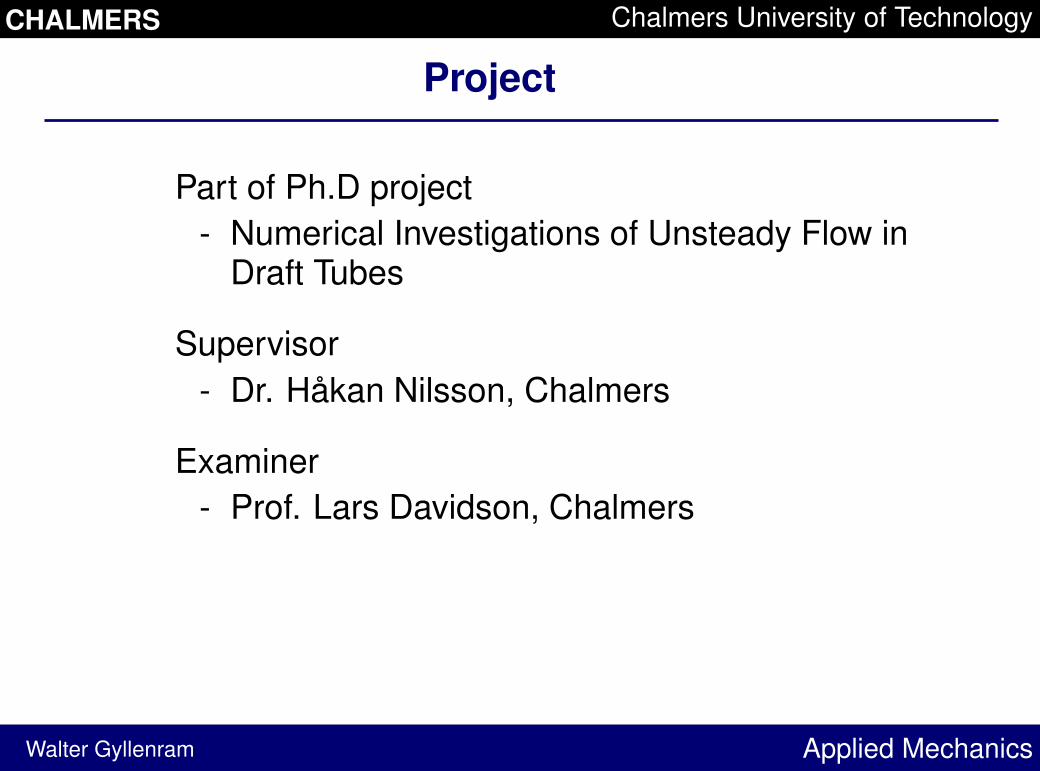
When a turbine is operating at part load a swirlingflow will exit the runner. This gives rise to anoscillating vortex core that cause vibrations and adecrease in efficiency.
CHALMERS Chalmers University of Technology
Applied Mechanics
Goals
Walter Gyllenram
of the present work:- To analyse how sensitive the flow is to modeled
turbulent length and time scales.
of future work:- To improve numerical simulations of unsteady
swirling flow in draft tubes.
CHALMERS Chalmers University of Technology
Applied Mechanics
Unsteady modeling methods - overview
Walter Gyllenram
LES An LES is obviously very good for predicting themost important unsteady motions of swirling flow. InLES, the energy containing eddies of the left handside of the turbulent kinetic energy spectrum mustbe resolved everywhere. As the modeled turbulentlength scales is assumed to be proportional to thelocal grid spacing, LES is not an option for the realapplication, because the Reynolds number of a realwater turbine flow (
��� � �� �) is too high.
URANS The (U)RANS turbulence models are tuned tosteady flow, i.e. to predict the effect of all unsteadymotions. This often results in steady solutions.
CHALMERS Chalmers University of Technology
Applied Mechanics
Unsteady methods
Walter Gyllenram
VLES In VLES, RANS models are used. However, awayfrom walls, where is easy (cheap) to resolve largescale structures, a filter is introduced. The modeledlength and time scales are compared to whatpotentially can be resolved in the simulation, and, iflarger, they are filtered. Contrary to LES, thenon-resolved (modeled) parts of the turbulent flowmay have length scales smaller than the local gridspacing. As compared to an LES, coarser grids canbe used. In this study, we generalize the filteringprocedure of Willems to a LRN
� � turbulencemodel.
CHALMERS Chalmers University of Technology
Applied Mechanics
Filtering the turbulent quantities
Walter Gyllenram
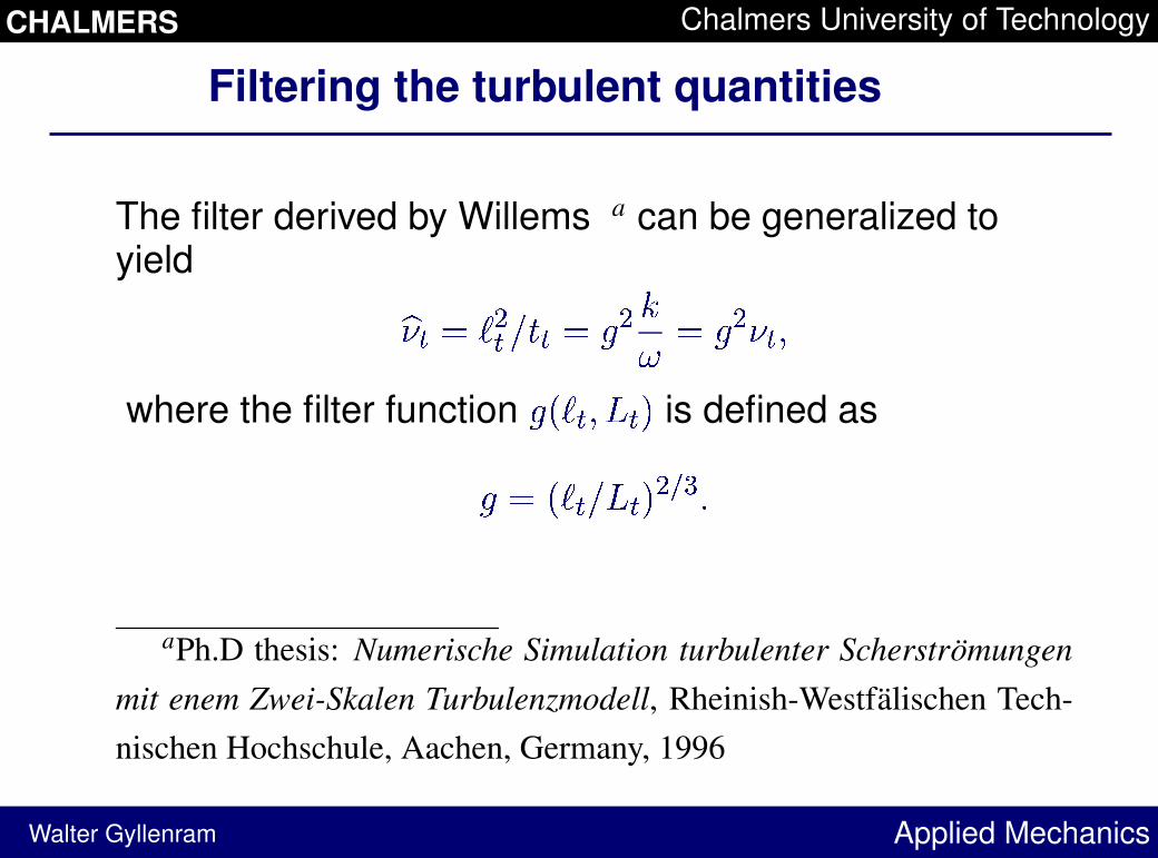
The filter derived by Willems a can be generalized toyield
��� � � � ��� � � � �� � � � �� ��
where the filter function � � � � � �
is defined as
� � � � � � � � ���
aPh.D thesis: Numerische Simulation turbulenter Scherstromungenmit enem Zwei-Skalen Turbulenzmodell, Rheinish-Westfalischen Tech-nischen Hochschule, Aachen, Germany, 1996
CHALMERS Chalmers University of Technology
Applied Mechanics
Upper limit of the turbulent length scale
Walter Gyllenram
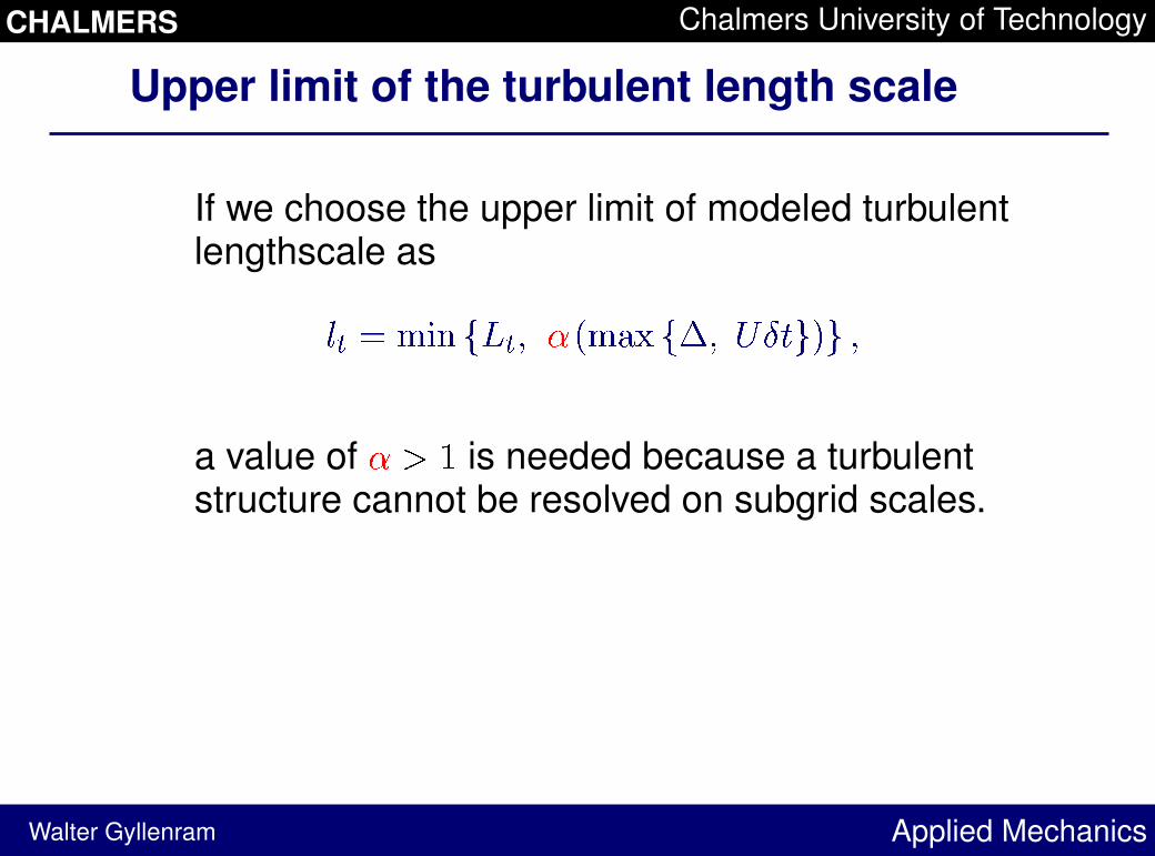
If we choose the upper limit of modeled turbulentlengthscale as
"! # $ %�& '( !�) * + $ ,- '. ) / 01 23 2)
a value of * 4 5
is needed because a turbulentstructure cannot be resolved on subgrid scales.
CHALMERS Chalmers University of Technology
Applied Mechanics
Upper limit of the turbulent length scale
Walter Gyllenram
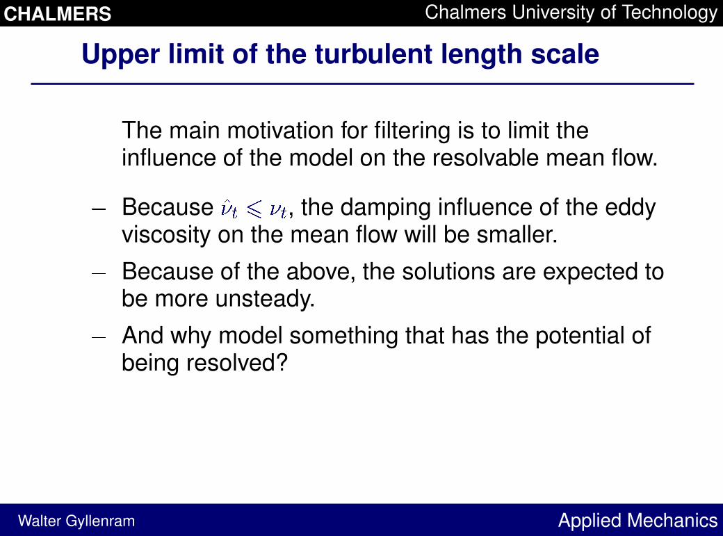
The main motivation for filtering is to limit theinfluence of the model on the resolvable mean flow.
6 Because
798�: ; 8�: , the damping influence of the eddyviscosity on the mean flow will be smaller.
6 Because of the above, the solutions are expected tobe more unsteady.
6 And why model something that has the potential ofbeing resolved?
CHALMERS Chalmers University of Technology
Applied Mechanics
Testcase
Walter Gyllenram
s
nPSfrag replacements <=>
?> > @> > A @>
BC D
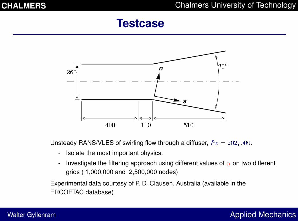
Unsteady RANS/VLES of swirling flow through a diffuser,
EGF H B C BJI C C C .
- Isolate the most important physics.
- Investigate the filtering approach using different values of K on two differentgrids ( 1,000,000 and 2,500,000 nodes)
Experimental data courtesy of P. D. Clausen, Australia (available in theERCOFTAC database)
CHALMERS Chalmers University of Technology
Applied Mechanics
Iime-averaged streamwise velocity
Walter Gyllenram
0 0.192 0.461 0.769 1.346
0
0.2
0.4
0.6
0.8
1
1.2
1.4
1.6
PSfrag replacements
L MN
O PQ 1.923 2.538 3.115
0
0.2
0.4
0.6
0.8
1
1.2
1.4
1.6
PSfrag replacements
L MN
O PQ
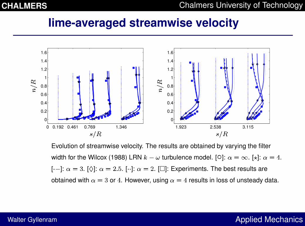
Evolution of streamwise velocity. The results are obtained by varying the filter
width for the Wilcox (1988) LRNRTS U turbulence model. [
V
]: WX Y. [ Z]: W X [
.
[ \S ]: W X ]
. [
^
]: WX _J` a. [ \ \ ]: W X _
. [
b
]: Experiments. The best results are
obtained with W X ]or
[. However, using W X [
results in loss of unsteady data.
CHALMERS Chalmers University of Technology
Applied Mechanics
Filter function c d
and eddy-viscosity
Walter Gyllenram
0.5 0.6 0.7 0.8 0.9 1
100
101
102
103
PSfrag replacements
ef
gihj k hj 0 50 100 150 200 250 300
100
101
102
103
PSfrag replacements
ef
gih lj
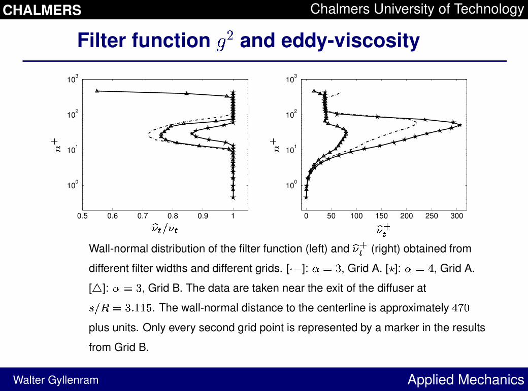
Wall-normal distribution of the filter function (left) and
g h lj (right) obtained from
different filter widths and different grids. [ mn ]: op q
, Grid A. [ r]: o p s
, Grid A.
[
t
]: op q
, Grid B. The data are taken near the exit of the diffuser at
u kv p qJw x xy
. The wall-normal distance to the centerline is approximately
sz{
plus units. Only every second grid point is represented by a marker in the results
from Grid B.
CHALMERS Chalmers University of Technology
Applied Mechanics
Frequencies of wall pressure
Walter Gyllenram
00.511.522.53
0
0.01
0.02
0.03
0.04
PSfrag replacements
|}~
��
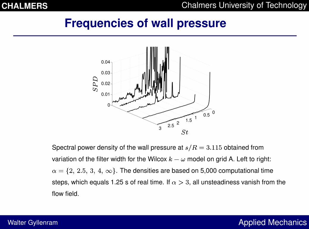
Spectral power density of the wall pressure at � �� � �J� � ��
obtained from
variation of the filter width for the Wilcox
�T� � model on grid A. Left to right:
� � ��J� � � � � �� �� � � . The densities are based on 5,000 computational time
steps, which equals 1.25 s of real time. If � � �
, all unsteadiness vanish from the
flow field.
CHALMERS Chalmers University of Technology
Applied Mechanics
Frequencies of wall pressure near the outlet
Walter Gyllenram
0 0.5 1 1.5 2 2.5 30
0.1
0.2
0.3
0.4
0.5
PSfrag replacements ���
�� 0 0.5 1 1.5 2 2.5 30
0.1
0.2
0.3
0.4
0.5
PSfrag replacements ���
��
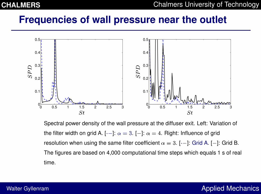
Spectral power density of the wall pressure at the diffuser exit. Left: Variation of
the filter width on grid A. [ �� ]: �� �. [� ]: � � �
. Right: Influence of grid
resolution when using the same filter coefficient � � �
. [ � � ]: Grid A. [� ]: Grid B.
The figures are based on 4,000 computational time steps which equals 1 s of real
time.
CHALMERS Chalmers University of Technology
Applied Mechanics
Resolved vortices
Walter Gyllenram
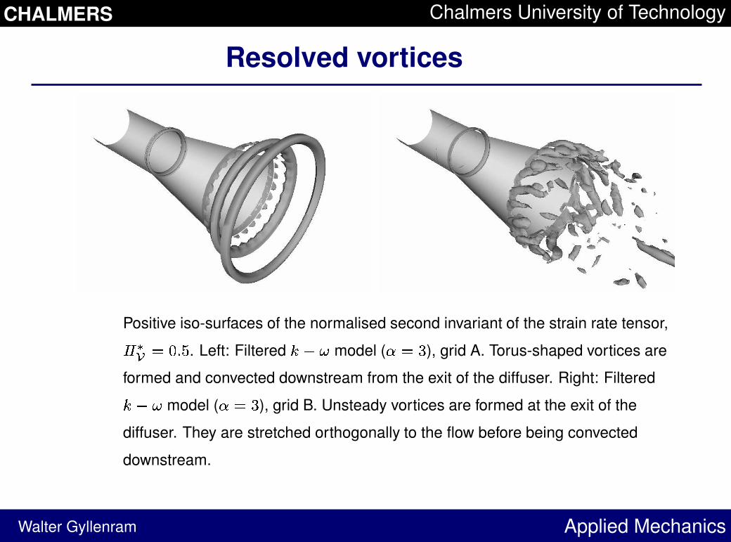
Positive iso-surfaces of the normalised second invariant of the strain rate tensor,� � ¢¡ £ ¤J¥ ¦
. Left: Filtered
§T¨ © model ( ª £ «
), grid A. Torus-shaped vortices are
formed and convected downstream from the exit of the diffuser. Right: Filtered§ ¨ © model ( ª £ «
), grid B. Unsteady vortices are formed at the exit of the
diffuser. They are stretched orthogonally to the flow before being convected
downstream.
CHALMERS Chalmers University of Technology
Applied Mechanics
Resolved vortices
Walter Gyllenram
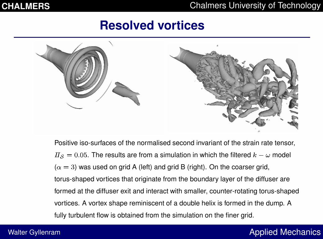
Positive iso-surfaces of the normalised second invariant of the strain rate tensor,¬ ¬® ¯ °J± °²
. The results are from a simulation in which the filtered
³T´ µ model
( ¶ ¯ ·
) was used on grid A (left) and grid B (right). On the coarser grid,
torus-shaped vortices that originate from the boundary layer of the diffuser are
formed at the diffuser exit and interact with smaller, counter-rotating torus-shaped
vortices. A vortex shape reminiscent of a double helix is formed in the dump. A
fully turbulent flow is obtained from the simulation on the finer grid.
CHALMERS Chalmers University of Technology
Applied Mechanics
Conclusions
Walter Gyllenram
- Filtering is in some cases necessary in order toobtain unsteady solutions.
- The filtering procedure improves the time-averagedresults as long as it is applied with some caution, i.e.it should not be active in the near wall region.Additional testcases using wall functions on acoarser grid showed that, for these cases, thesolutions were not as sensitive to the value of alpha.
- The main frequency of the flow is not sensitive to ofthe choice of the filter width.
- A grid refinement introduces overtones, but also ahigh density of a lower frequency.
CHALMERS Chalmers University of Technology
Applied Mechanics
Acknowledgements
Walter Gyllenram
This project is financed by SVC (www.svc.nu):
Swedish Energy Agency, ELFORSK, SvenskaKraftnät a
Chalmers, LTU, KTH, UU
We would also like to thank Dr. Albert Ruprecht atIHS, Stuttgart, for his support during this work.
aCompanies involved: CarlBro, E.ON Vattenkraft Sverige, FortumGeneration, Jamtkraft, Jonkoping Energi, Malarenergi, Skelleftea Kraft,Sollefteaforsens, Statoil Lubricants, Sweco VBB, Sweco Energuide,SweMin, Tekniska Verken i Linkoping, Vattenfall Research and Devel-opment, Vattenfall Vattenkraft, Waplans, VG Power and Oresundskraft