Embed Size (px)
Citation preview
2
21
•
•
SLEWING RING SELECTION
SLEWING RINGS FUNCTIONS
OTHER FEATURES
22
SLEWING RING FUNCTIONSL O A D S S E L E C T I O N
The slewing ring, being the link between a mobile element and a fixed base, must have the capacity to transmit the stresses of the mobile part towards the base. It is necessary to accurately define all the actual stresses applied so that a suitable slewing ring with adequate capacity can be selected. This should include the effects due to masses and inertias of the payloads and structures.
It is necessary to distinguish the fixed loads and the variable loads as well as the effects due to dynamic loads, the latter constituting "fatigue" stresses.The direction of forces affecting the slewing ring must be well defined so that the active tilting moment can be established.
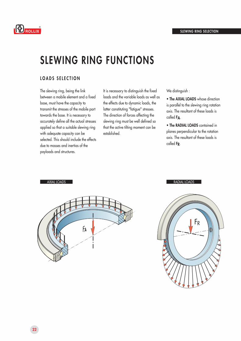
We distinguish :
• The AXIAL LOADS whose directionis parallel to the slewing ring rotationaxis. The resultant of these loads iscalled FA.
• The RADIAL LOADS contained inplanes perpendicular to the rotationaxis. The resultant of these loads iscalled FR.
SLEWING RING SELECTION
AXIAL LOADS RADIAL LOADS
23
2
SLEWING RING FUNCTIONSL O A D S S E L E C T I O N
CALCULATION OF THE EQUIVALENT LOADFor the calculation, the resultant of the radial loads FR is transposed into an equivalent axial load using a factor KR as follows :
For standard slewing ring :if :FR < 0,25FA
if :
0,25 < FR < 1FA
if :FR > 1FA
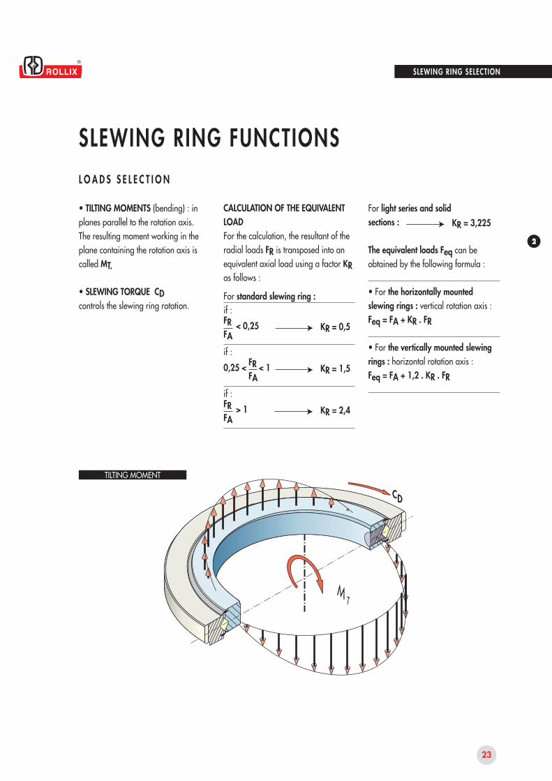
• TILTING MOMENTS (bending) : inplanes parallel to the rotation axis.The resulting moment working in theplane containing the rotation axis iscalled MT.
• SLEWING TORQUE CDcontrols the slewing ring rotation.
SLEWING RING SELECTION
KR = 0,5
KR = 1,5
KR = 2,4
For light series and solidsections :
The equivalent loads Feq can be obtained by the following formula :
• For the horizontally mountedslewing rings : vertical rotation axis :Feq = FA + KR . FR
• For the vertically mounted slewingrings : horizontal rotation axis :Feq = FA + 1,2 . KR . FR
KR = 3,225
TILTING MOMENT
3, Rue Louis Renault B.P. 329
F - 44803 ST HERBLAIN Cedex
Tel. 33 (0)2 40 67 89 89
Fax 33 (0)2 40 67 89 03
E-mail : [email protected]
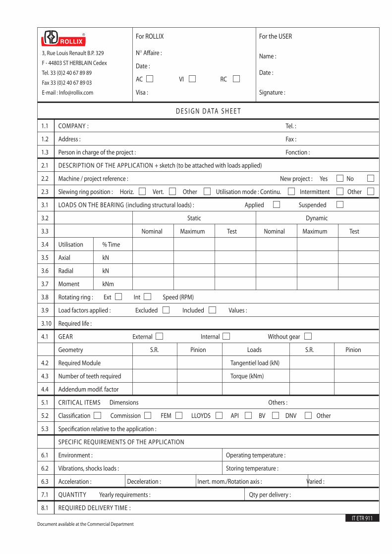
D E S I G N D ATA S H E E T
1.1
1.2
1.3
2.1
2.2
2.3
3.1
3.2
3.3
3.4
3.5
3.6
3.7
3.8
3.9
3.10
4.1
4.2
4.3
4.4
5.1
5.2
5.3
6.1
6.2
6.3
7.1
8.1
COMPANY :
Address :
Person in charge of the project :
DESCRIPTION OF THE APPLICATION + sketch (to be attached with loads applied)
Machine / project reference :
Slewing ring position : Horiz. Vert. Other Utilisation mode : Continu. Intermittent Other
LOADS ON THE BEARING (including structural loads) : Applied Suspended
Utilisation
Axial
Radial
Moment
Rotating ring : Ext Int Speed (RPM)
Load factors applied : Excluded Included Values :
Required life :
GEAR
Geometry
Required Module
Number of teeth required
Addendum modif. factor
CRITICAL ITEMS
Classification Commission FEM LLOYDS API BV DNV Other
Specification relative to the application :
SPECIFIC REQUIREMENTS OF THE APPLICATION
Environment :
Vibrations, shocks loads :
Acceleration :
QUANTITY Yearly requirements :
REQUIRED DELIVERY TIME :
Tel. :
Fax :
Fonction :
New project : Yes No
% Time
kN
kN
kNm
Nominal Maximum Test Nominal Maximum Test
External Internal Without gear
S.R. Pinion Loads S.R. Pinion
Tangentiel load (kN)
Torque (kNm)
Dimensions Others :
Operating temperature :
Storing temperature :
Deceleration : Inert. mom./Rotation axis : Varied :
Qty per delivery :
For ROLLIX
N° Affaire :
Date :
AC VI RC
Visa :
For the USER
Name :
Date :
Signature :
Static Dynamic
IT ETR 911Document available at the Commercial Department
25
2
SLE WING RING SELEC TION
SKE TCH OF YOUR APPLICATIONSHOWING THE LOAD POSITIONS
26
SLEWING RING SELECTION
SLEWING RING FUNCTIONSB E A R I N G F U N C T I O N
The knowledge of loads and working conditions is necessary to allow us to design and dimension the "BEARING" function of the slewing ring i.e : movement type, speed, accelerations, temperatures, environment, etc.
The transmission of loads from one raceway to another varies according to the nature of applied loads.In order to calculate the ideal dimensions of the raceway, we define the load equivalent to all external efforts in the most stressed areas.These loads are corrected by factors according to the application, the usage, etc.We distinguish between :- the application factor- the usage factor- the safety factor
THE APPLICATION FACTOR KAis a coefficient taking into account the application specificity in relation to the slewing ring element.This factor is established from ROLLIX experience. It is defined in the table "APPLICATION FACTORS".
KAKUKS
THE USAGE FACTOR KUis defined according to the particular operating conditions : vibrations, shocks, occasional or accidental overloading, etc. If no other value is specified, then the nominal value is taken as 1.
THE SAFETY FACTOR KSis defined from standardized criteria for applications which must meet specific regulations such as : FEM, LLOYDS, API... This generally has the value 1,as the designer of the machine must include the regulation factors in the calculation of the loads applied on the bearing.
27
2
SLEWING RING SELECTION
SLEWING RING FUNCTIONSB E A R I N G F U N C T I O N
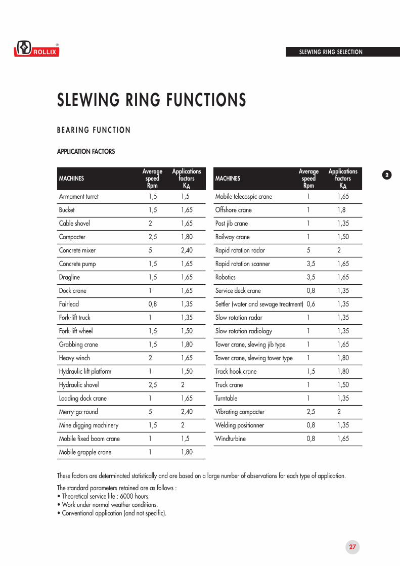
APPLICATION FACTORS
Armament turret
Bucket
Cable shovel
Compacter
Concrete mixer
Concrete pump
Dragline
Dock crane
Fairlead
Fork-lift truck
Fork-lift wheel
Grabbing crane
Heavy winch
Hydraulic lift platform
Hydraulic shovel
Loading dock crane
Merry-go-round
Mine digging machinery
Mobile fixed boom crane
Mobile grapple crane
1,5
1,5
2
2,5
5
1,5
1,5
1
0,8
1
1,5
1,5
2
1
2,5
1
5
1,5
1
1
1,5
1,65
1,65
1,80
2,40
1,65
1,65
1,65
1,35
1,35
1,50
1,80
1,65
1,50
2
1,65
2,40
2
1,5
1,80
Mobile telecospic crane
Offshore crane
Post jib crane
Railway crane
Rapid rotation radar
Rapid rotation scanner
Robotics
Service deck crane
Settler (water and sewage treatment)
Slow rotation radar
Slow rotation radiology
Tower crane, slewing jib type
Tower crane, slewing tower type
Track hook crane
Truck crane
Turntable
Vibrating compacter
Welding positionner
Windturbine
1
1
1
1
5
3,5
3,5
0,8
0,6
1
1
1
1
1,5
1
1
2,5
0,8
0,8
1,65
1,8
1,35
1,50
2
1,65
1,65
1,35
1,35
1,35
1,35
1,65
1,80
1,80
1,50
1,35
2
1,35
1,65
MACHINESAveragespeedRpm
Applicationsfactors
KAMACHINES
AveragespeedRpm
Applicationsfactors
KA
These factors are determinated statistically and are based on a large number of observations for each type of application.
The standard parameters retained are as follows :• Theoretical service life : 6000 hours.• Work under normal weather conditions.• Conventional application (and not specific).
28
Px
Py
O
Px
Py
O
MT
MT
SLEWING RING SELECTION
SLEWING RING FUNCTIONSB E A R I N G F U N C T I O N
Selection of the ring according to capacity
The load capacity of the slewing ring iscalculated according to its performance in function of :• its geometric envelope,• the nature of the ring materials, • the heat treatment carried out,• the nature, the number and the dimension of the rolling elements, • the contact parameters of the rolling elements.
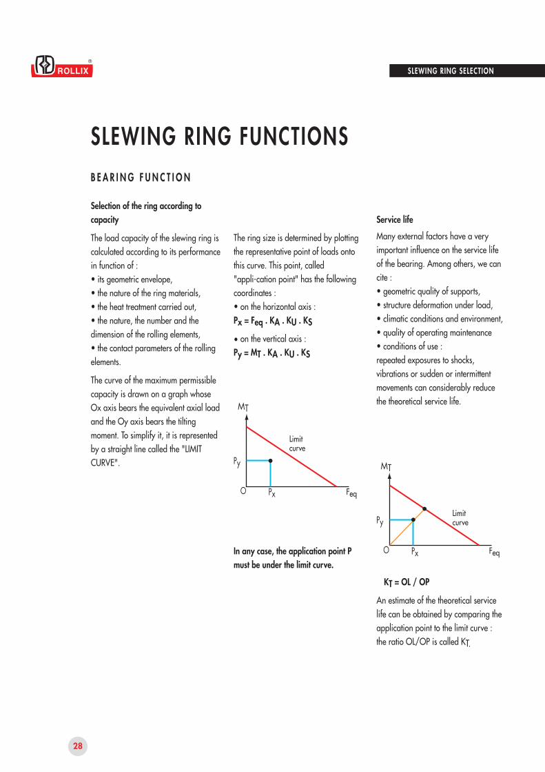
The curve of the maximum permissiblecapacity is drawn on a graph whose Ox axis bears the equivalent axial load and the Oy axis bears the tilting moment. To simplify it, it is represented by a straight line called the "LIMIT CURVE".
Limitcurve
Feq
Feq
Service life
Many external factors have a very important influence on the service life of the bearing. Among others, we can cite :• geometric quality of supports,• structure deformation under load,• climatic conditions and environment,• quality of operating maintenance• conditions of use :repeated exposures to shocks, vibrations or sudden or intermittent movements can considerably reduce the theoretical service life.
KT = OL / OP
An estimate of the theoretical service life can be obtained by comparing the application point to the limit curve :the ratio OL/OP is called KT.
The ring size is determined by plotting the representative point of loads onto this curve. This point, called "appli-cation point" has the following coordinates :• on the horizontal axis :Px = Feq . KA . KU . KS
• on the vertical axis :Py = MT . KA . KU . KS
In any case, the application point P must be under the limit curve.
Limitcurve
29
275 00050 000
25 000
10 0007 5005 000
2 500
1 0001 1,5 2 2,5 3
2 4 6 8 10 12 14
1,2
1,0
0,8
0,6
0,4
0,2
D
KV
SLEWING RING SELECTION
SLEWING RING FUNCTIONSB E A R I N G F U N C T I O N
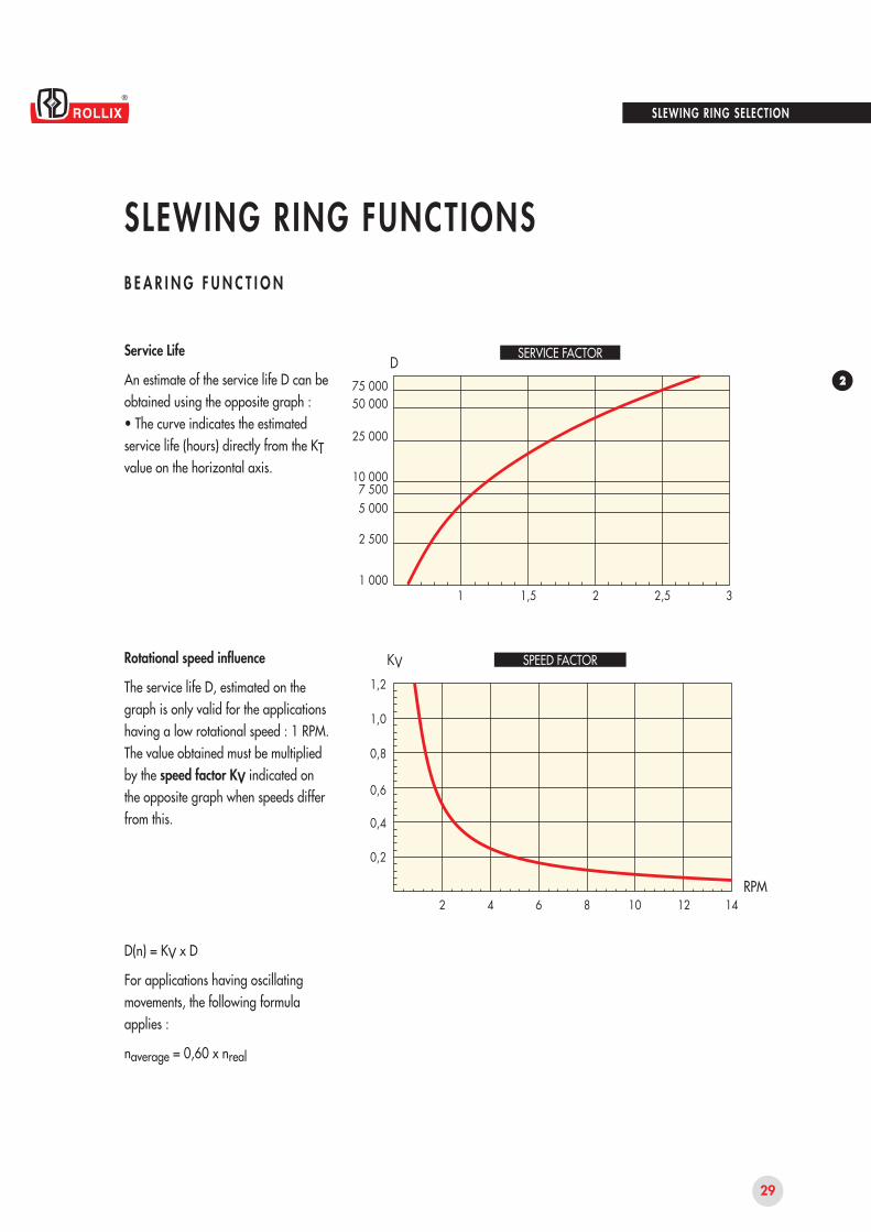
Service Life
An estimate of the service life D can be obtained using the opposite graph :• The curve indicates the estimatedservice life (hours) directly from the KT value on the horizontal axis.
Rotational speed influence
The service life D, estimated on the graph is only valid for the applications having a low rotational speed : 1 RPM.The value obtained must be multiplied by the speed factor KV indicated on the opposite graph when speeds differ from this.
D(n) = KV x D
For applications having oscillating movements, the following formula applies :
naverage = 0,60 x nreal
RPM
SERVICE FACTOR
SPEED FACTOR
30
8.8
10.9
12.9
800
1040
1220
640
940
1100
40
40
40
SLEWING RING SELECTION
SLEWING RING FUNCTIONSFA S T E N I N G F U N C T I O N
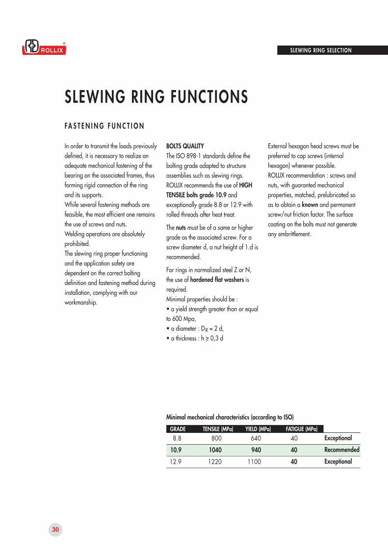
Minimal mechanical characteristics (according to ISO)
In order to transmit the loads previously defined, it is necessary to realize an adequate mechanical fastening of the bearing on the associated frames, thus forming rigid connection of the ring and its supports.While several fastening methods are feasible, the most efficient one remains the use of screws and nuts.Welding operations are absolutely prohibited.The slewing ring proper functioning and the application safety are dependent on the correct bolting definition and fastening method during installation, complying with our workmanship.
External hexagon head screws must be preferred to cap screws (internal hexagon) whenever possible.ROLLIX recommendation : screws and nuts, with guaranted mechanical properties, matched, prelubricated so as to obtain a known and permanent screw/nut friction factor. The surface coating on the bolts must not generate any embrittlement.
GRADE TENSILE (MPa) YIELD (MPa) FATIGUE (MPa)
BOLTS QUALITYThe ISO 898-1 standards define the bolting grade adapted to structure assemblies such as slewing rings.ROLLIX recommends the use of HIGH TENSILE bolts grade 10.9 and exceptionally grade 8.8 or 12.9 with rolled threads after heat treat.
The nuts must be of a same or highergrade as the associated screw. For a screw diameter d, a nut height of 1.d is recommended.
For rings in normalized steel Z or N,the use of hardened flat washers is required.Minimal properties should be :• a yield strength greater than or equal to 600 Mpa,• a diameter : DR = 2 d,• a thickness : h > 0,3 d
Exceptional
Recommended
Exceptional
31
2
d
L K
L K
FA
FA
SLEWING RING SELECTION
SLEWING RING FUNCTIONSFA S T E N I N G F U N C T I O N
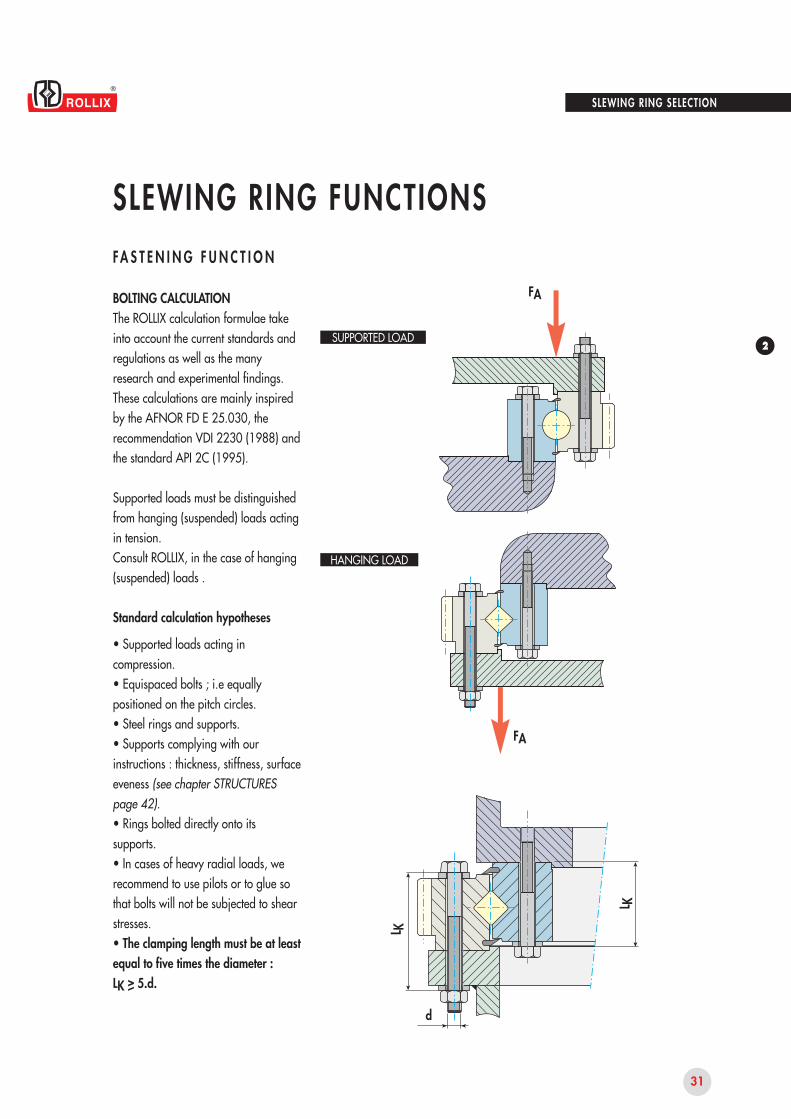
BOLTING CALCULATIONThe ROLLIX calculation formulae take into account the current standards and regulations as well as the many research and experimental findings.These calculations are mainly inspired by the AFNOR FD E 25.030, the recommendation VDI 2230 (1988) and the standard API 2C (1995).
Supported loads must be distinguished from hanging (suspended) loads acting in tension.Consult ROLLIX, in the case of hanging (suspended) loads .
Standard calculation hypotheses
• Supported loads acting incompression.• Equispaced bolts ; i.e equallypositioned on the pitch circles.• Steel rings and supports.• Supports complying with ourinstructions : thickness, stiffness, surfaceeveness (see chapter STRUCTURESpage 42).• Rings bolted directly onto itssupports.• In cases of heavy radial loads, werecommend to use pilots or to glue sothat bolts will not be subjected to shearstresses.• The clamping length must be at leastequal to five times the diameter :LK > 5.d.
HANGING LOAD
SUPPORTED LOAD
2 3 4 5 6 7 8
2,75
2,50
2,25
2,00
1,75
1,50
1,25
1,00
33
d
30
27242220161412
32
Fk
Lk/d
SLEWING RING SELECTION
SLEWING RING FUNCTIONSFA S T E N I N G F U N C T I O N S
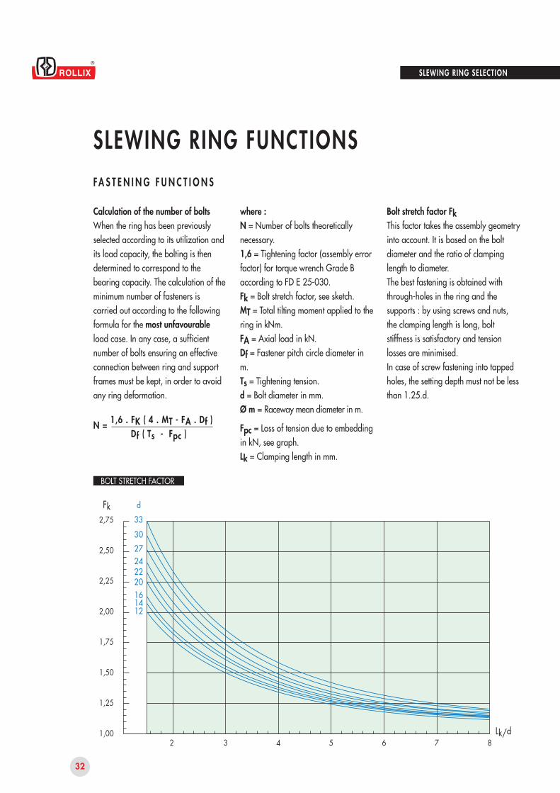
Calculation of the number of boltsWhen the ring has been previously selected according to its utilization and its load capacity, the bolting is then determined to correspond to the bearing capacity. The calculation of the minimum number of fasteners is carried out according to the following formula for the most unfavourable load case. In any case, a sufficient number of bolts ensuring an effective connection between ring and support frames must be kept, in order to avoid any ring deformation.
N = 1,6 . FK ( 4 . MT - FA . Df )Df ( Ts - Fpc )
where :N = Number of bolts theoretically necessary.1,6 = Tightening factor (assembly error factor) for torque wrench Grade B according to FD E 25-030.Fk = Bolt stretch factor, see sketch.MT = Total tilting moment applied to the ring in kNm.FA = Axial load in kN.Df = Fastener pitch circle diameter in m.Ts = Tightening tension.d = Bolt diameter in mm.Ø m = Raceway mean diameter in m.
Fpc = Loss of tension due to embedding in kN, see graph.Lk = Clamping length in mm.
Bolt stretch factor FkThis factor takes the assembly geometry into account. It is based on the bolt diameter and the ratio of clamping length to diameter.The best fastening is obtained with through-holes in the ring and the supports : by using screws and nuts, the clamping length is long, bolt stiffness is satisfactory and tension losses are minimised.In case of screw fastening into tapped holes, the setting depth must not be less than 1.25.d.
BOLT STRETCH FACTOR
2
8
7
6
5
4
3
2
1
333027242220161412
2 4 6 8 10
33
Fpc
Di
Db
dw
d
Lk/d
d
SLEWING RING SELECTION
SLEWING RING FUNCTIONSFA S T E N I N G F U N C T I O N S
Tightening tension : TsTightening tension of fastening bolts must be sufficient to warrant theabsence of looseness which is essential to ensure the resistance of the assembly fatigue.
Calculation of the minimum fastenerpreload :It is useful to check that the standar-dized preload of the chosen bolt
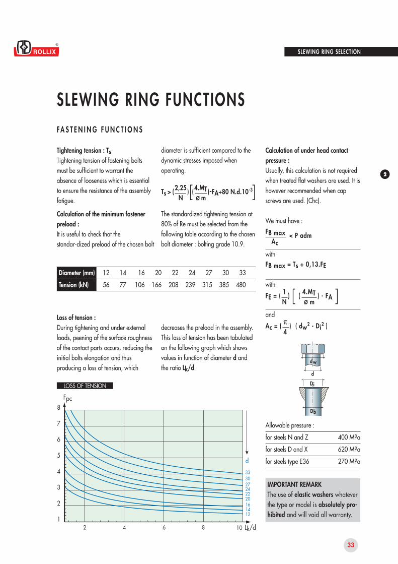
Loss of tension :During tightening and under external loads, peening of the surface roughness of the contact parts occurs, reducing the initial bolts elongation and thus producing a loss of tension, which
12
56
14
77
16
106
22
208
24
239
27
315
30
385
33
480
20
166
Diameter (mm)
Tension (kN)
diameter is sufficient compared to the dynamic stresses imposed when operating.
Ts > ( 2,25 )[( 4.MT )-FA+80 N.d.10-3]N Ø m
The standardized tightening tension at80% of Re must be selected from the following table according to the chosen bolt diameter : bolting grade 10.9.
decreases the preload in the assembly.This loss of tension has been tabulated on the following graph which shows values in function of diameter d and the ratio Lk/d.
Calculation of under head contact pressure :Usually, this calculation is not required when treated flat washers are used. It is however recommended when cap screws are used. (Chc).
We must have :
FB max < P admAc
withFB max = Ts + 0,13.FE
with
FE = ( 1 ) [ ( 4.MT ) - FA ]N Ø m
and
Ac = ( π ) ( dw2 - Di2 )4
400 MPa
620 MPa
270 MPa
Allowable pressure :
for steels N and Z
for steels D and X
for steels type E36
IMPORTANT REMARKThe use of elastic washers whateverthe type or model is absolutely pro-hibited and will void all warranty.
LOSS OF TENSION
34
20 40 60 80 100 120 140 160 180
2,0
1,8
1,6
1,4
1,2
1,0
0,8
0,6
0,4
0,2
0
0,2
0,4
0,6
0,8
Z1+Z2
SLEWING RING FUNCTIONSS L E W I N G F U N C T I O N
RESISTANCEOur rating graphs indicate the values of allowable maximum tangential force in fatigue T.The continuous operating capacity is obtained by the application of a suitable load moderating factor.
T = 2 CD DrefCd = Torque on gearDref = Reference diameterUnless otherwise stated, the indicated values are valid for geared rings made of normalized steel XC45 : code Z. When these values are not sufficient, ROLLIX can proceed with contour hardening which considerably improves the resistance to tooth root bending and the resistance to contact pressure. For very heavy loading conditions, ROLLIX carries out complete hardening of the tooth and of its root in the wheel rim. When only a better wear resistance is required, surface hardening of tooth flanks only is possible.
ROLLIX slewing rings generally incorporate a SLEWING mechanism to control rotation of the mobile part. This function can be achieved by various means :
gear drive (the most frequent case)
belt drive
chain drive
direct drive
GEAR DRIVEInvolute teeth, spur or helical are directly cut into the outer or inner ring (spur gear only).
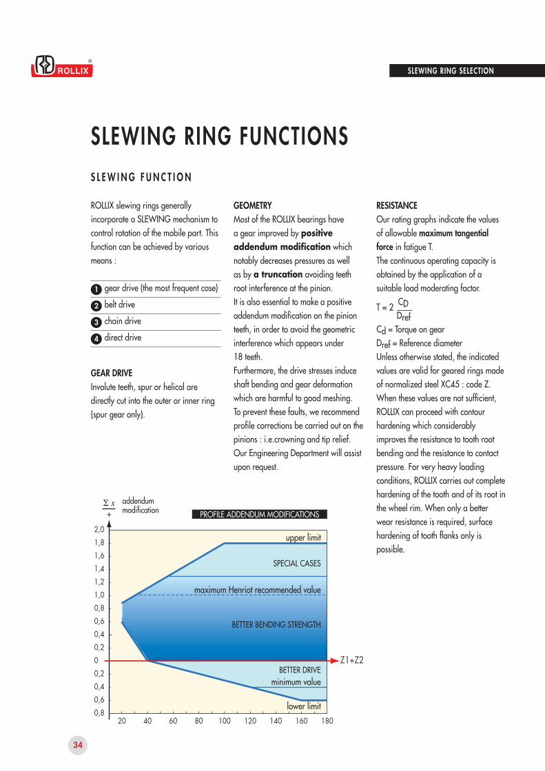
GEOMETRYMost of the ROLLIX bearings have a gear improved by positive addendum modification which notably decreases pressures as well as by a truncation avoiding teeth root interference at the pinion.It is also essential to make a positive addendum modification on the pinion teeth, in order to avoid the geometric interference which appears under18 teeth.Furthermore, the drive stresses induce shaft bending and gear deformation which are harmful to good meshing.To prevent these faults, we recommend profile corrections be carried out on the pinions : i.e.crowning and tip relief. Our Engineering Department will assist upon request.
1
2
3
4
upper limit
maximum Henriot recommended value
minimum value
SPECIAL CASES
BETTER BENDING STRENGTH
BETTER DRIVE
lower limit
addendummodification
SLEWING RING SELECTION
PROFILE ADDENDUM MODIFICATIONS
35
2
SLEWING RING FUNCTIONSS L E W I N G F U N C T I O N
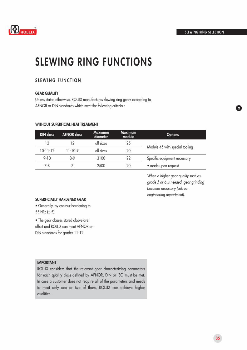
Maximumdiameter
MaximummoduleDIN class AFNOR class Options
12
10-11-12
9-10
7-8
12
11-10-9
8-9
7
all sizes
all sizes
3100
2500
25
20
22
20
SUPERFICIALLY HARDENED GEAR• Generally, by contour hardening to 55 HRc (± 5).
• The gear classes stated above are offset and ROLLIX can meet AFNOR or DIN standards for grades 11-12.
When a higher gear quality such as grade 5 or 6 is needed, gear grinding becomes necessary (ask our Engineering department).
WITHOUT SUPERFICIAL HEAT TREATMENT
IMPORTANTROLLIX considers that the relevant gear characterizing parameters for each quality class defined by AFNOR, DIN or ISO must be met. In case a customer does not require all of the parameters and needs to meet only one or two of them, ROLLIX can achieve higher qualities.
Module 45 with special tooling
Specific equipment necessary
• made upon request
SLEWING RING SELECTION
GEAR QUALITYUnless stated otherwise, ROLLIX manufactures slewing ring gears according to AFNOR or DIN standards which meet the following criteria :
36
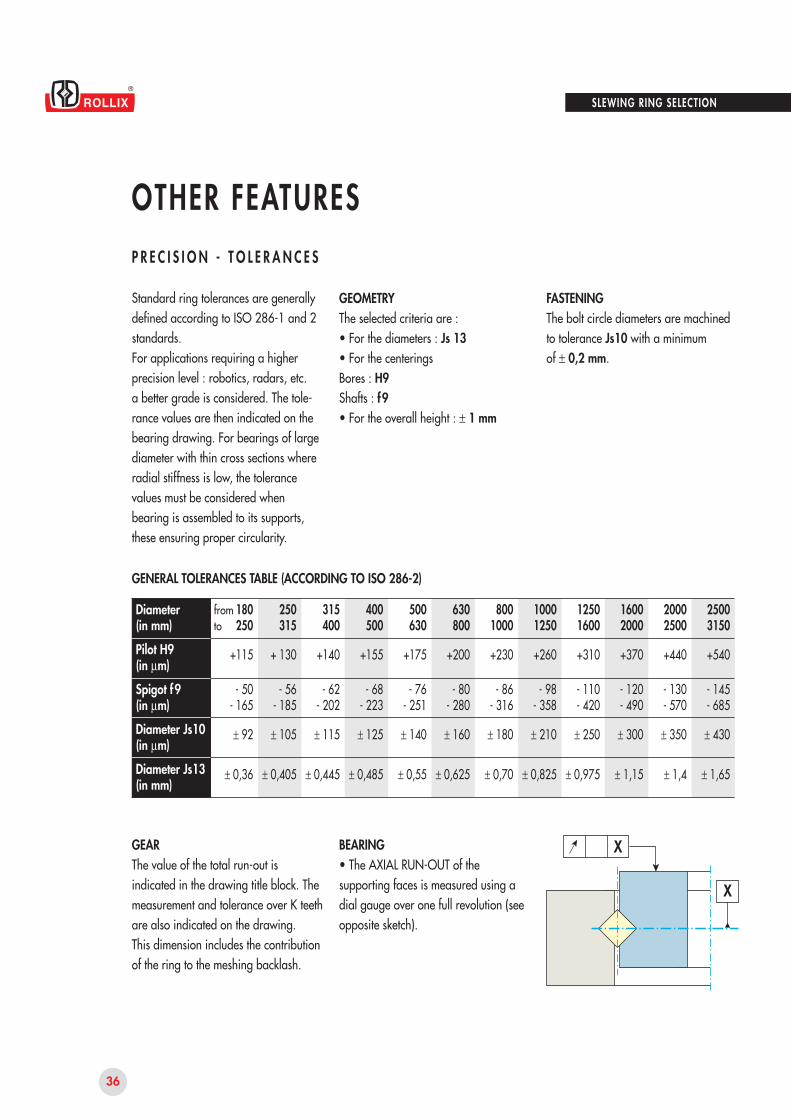
X
X
SLEWING RING SELECTION
OTHER FEATURESP R E C I S I O N - T O L E R A N C E S
Standard ring tolerances are generally defined according to ISO 286-1 and 2 standards.For applications requiring a higher precision level : robotics, radars, etc.a better grade is considered. The tole- rance values are then indicated on the bearing drawing. For bearings of large diameter with thin cross sections where radial stiffness is low, the tolerance values must be considered when bearing is assembled to its supports, these ensuring proper circularity.
GEOMETRYThe selected criteria are : • For the diameters : Js 13• For the centeringsBores : H9Shafts : f9• For the overall height : ± 1 mm
FASTENINGThe bolt circle diameters are machined to tolerance Js10 with a minimumof ± 0,2 mm.
GENERAL TOLERANCES TABLE (ACCORDING TO ISO 286-2)
GEARThe value of the total run-out is indicated in the drawing title block. The measurement and tolerance over K teeth are also indicated on the drawing.This dimension includes the contribution of the ring to the meshing backlash.
BEARING• The AXIAL RUN-OUT of the supporting faces is measured using a dial gauge over one full revolution (see opposite sketch).
fromto
180250
+115
- 50- 165
± 92
± 0,36
250315
+ 130
- 56- 185
± 105
± 0,405
315400
+140
- 62- 202
± 115
± 0,445
400500
+155
- 68- 223
± 125
± 0,485
500630
+175
- 76- 251
± 140
± 0,55
630800
+200
- 80- 280
± 160
± 0,625
8001000
+230
- 86- 316
± 180
± 0,70
10001250
+260
- 98- 358
± 210
± 0,825
12501600
+310
- 110- 420
± 250
± 0,975
16002000
+370
- 120- 490
± 300
± 1,15
20002500
+440
- 130- 570
± 350
± 1,4
25003150
+540
- 145- 685
± 430
± 1,65
Diameter(in mm)
Pilot H9(in μm)
Spigot f9(in μm)
Diameter Js10(in μm)
Diameter Js13(in mm)
37
2
0,80
0,70
0,60
0,50
0,40
0,30
0,20
0,10
500 1000 1500 2000 2500 3000
YY
mm
F
SLEWING RING SELECTION
OTHER FEATURESP R E C I S I O N - T O L E R A N C E S
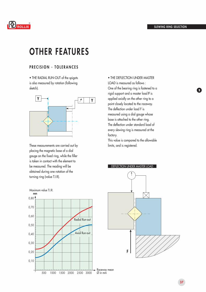
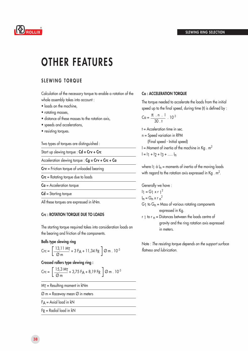
• THE RADIAL RUN-OUT of the spigots is also measured by rotation (following sketch).
These measurements are carried out by placing the magnetic base of a dial gauge on the fixed ring, while the filler is taken in contact with the element to be measured. The reading will be obtained during one rotation of the turning ring (value T.I.R).
• THE DEFLECTION UNDER MASTER LOAD is measured as follows :One of the bearing ring is fastened to a rigid support and a master load F is applied axially on the other ring to a point closely located to the raceway.The deflection under load F is measured using a dial gauge whose base is attached to the other ring.The deflection under standard load of every slewing ring is measured at the factory.This value is compared to the allowable limits, and is registered.
Raceway meanØ in mm
Maximum value T.I.R.
Radial Run-out
Axial Run-out
mm
DEFLECTION UNDER MASTER LOAD
38
SLEWING RING SELECTION
OTHER FEATURESS L E W I N G T O R Q U E
Calculation of the necessary torque to enable a rotation of the whole assembly takes into account :• loads on the machine,• rotating masses,• distance of these masses to the rotation axis,• speeds and accelerations,• resisting torques.
Two types of torques are distinguished :
Start up slewing torque : Cd = Crv + Crc
Acceleration slewing torque : Cg = Crv + Crc + Ca
Crv = Friction torque of unloaded bearing
Crc = Rotating torque due to loads
Ca = Acceleration torque
Cd = Starting torque
All these torques are expressed in kNm.
Crc : ROTATION TORQUE DUE TO LOADS
The starting torque required takes into consideration loads on the bearing and friction of the components.
Balls type slewing ring
Crc = [ 13,11 MT + 3 FA + 11,34 FR ] Ø m . 10-3
Ø m
Crossed rollers type slewing ring :
Crc = [ 15,3 MT + 3,75 FA + 8,19 FR ] Ø m . 10-3
Ø m
MT = Resulting moment in kNm
Ø m = Raceway mean Ø in meters
FA = Axial load in kN
FR = Radial load in kN
Ca : ACCELERATION TORQUE
The torque needed to accelerate the loads from the initialspeed up to the final speed, during time (t) is defined by :
Ca = π . n . I . 10-3
30 . t
t = Acceleration time in sec.n = Speed variation in RPM
(Final speed - Initial speed)I = Moment of inertia of the machine in Kg . m2
I = I1 + I2 + I3 + ..... In
where I1 à In = moments of inertia of the moving loads with regard to the rotation axis expressed in Kg . m2.
Generally we have :I1 = G1 x r 12
In = Gn x r n2
G1 to Gn = Mass of various rotating componentsexpressed in Kg.
r 1 to r n = Distances between the loads centre ofgravity and the ring rotation axis expressedin meters.
Note : The resisting torque depends on the support surfaceflatness and lubrication.
39
2
1,5
1
0,5
0,5 1 1,5 2 2,5 3
2
1,5 m
6800 kg500 kg
SLEWING RING SELECTION
OTHER FEATURESS L E W I N G T O R Q U E
LOADS APPLIED ON THE RING
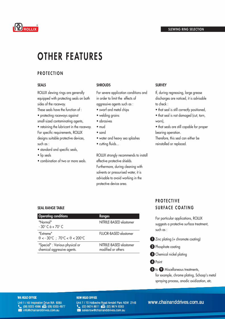
Axial FA : 68 kN + 5 kN = 73 kNRadial FR : 0,29 kN, negligibleMoment MT : 5 kN x 1,5 m = 7,5 kNm
SLEWING TORQUE : Raceway mean Ø = 2 metersCrv : according to the graph : 1 kNm
Crc = [ 13,11 x 7,5 + (73 x 3) + (11,34 x 0)] 2.10-3
2
Crc = 0,536 kNm
Slewing torque at start upCd = 1 + 0,536 = 1,536 kNm
Platform moment of inertia :
MR2 = 6800 x 22 = 13600 Kg m2
2 2
Cube moment of inertia :Mr2 = 500 x 1,52 = 1125 Kg m2
Total moment of inertia :13600 + 1125 = 14725 Kg m2
Acceleration torque :n = 6 - 2 = 4 RPM
Acceleration time : 20 sec
Ca = 14725 x π x 4 10-3 = 0,3084 kNm30 x 20
Slewing torque during accelerationCg = 1 + 0,536 + 0,3084 = 1,845 kNm
APPLICATION EXAMPLE
Platform diameter : 4 m.Platform mass : 6800 kgCube mass : 500 kgBall type slewing ringraceway mean Ø : 2 m.Distance from the cube to the rotation axis : 1,5 m.Initial speed : 2 RPMFinal speed : 6 RPMAcceleration time : 20 sec.
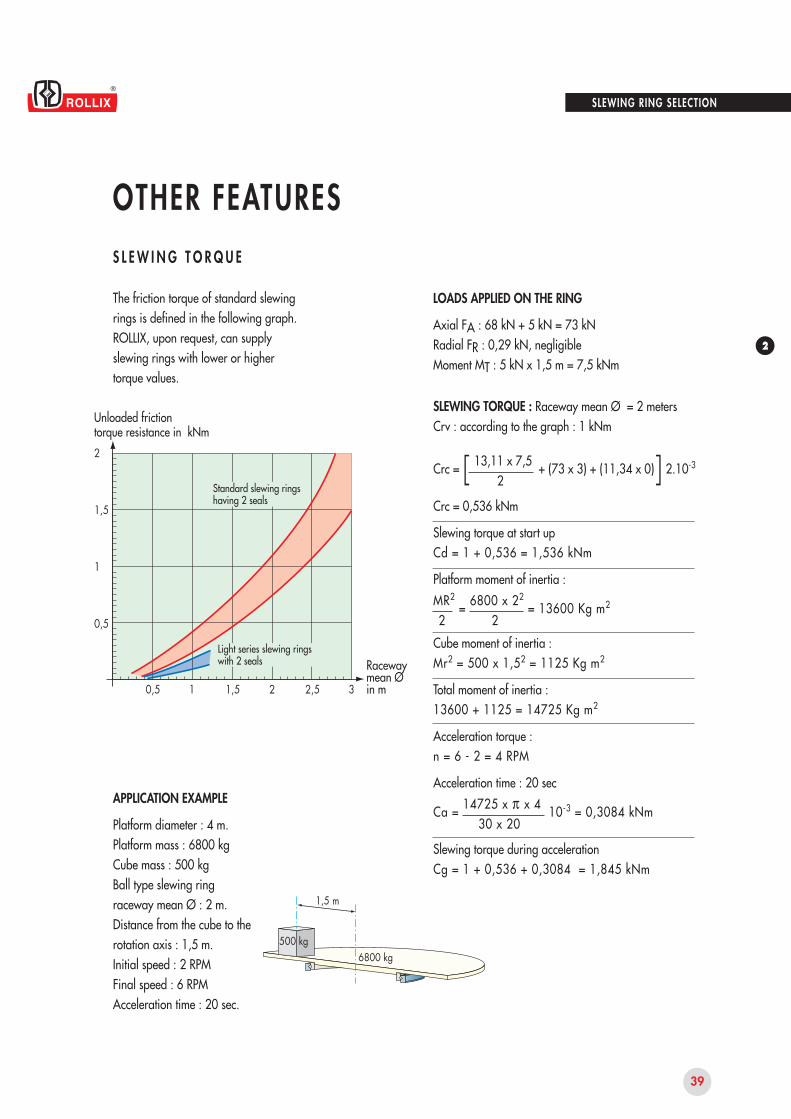
Unloaded frictiontorque resistance in kNm
Standard slewing rings having 2 seals
Light series slewing ringswith 2 seals Raceway
mean Ø in m
The friction torque of standard slewing rings is defined in the following graph.ROLLIX, upon request, can supply slewing rings with lower or higher torque values.
40
SLEWING RING SELECTION
OTHER FEATURESP R O T E C T I O N
SEAL RANGE TABLE
Operating conditions Ranges
SEALS
ROLLIX slewing rings are generallyequipped with protecting seals on both sides of the raceway.These seals have the function of : • protecting raceways againstsmall-sized contaminating agents,• retaining the lubricant in the raceway.For specific requirements, ROLLIXdesigns suitable protective devices,such as :• standard and specific seals,• lip seals• combination of two or more seals.
SHROUDS
For severe application conditions andin order to limit the effects of aggressive agents such as :• swarf and metal chips• welding grains• abrasives• mud• sand• water and heavy sea splashes• cutting fluids...
ROLLIX strongly recommends to install effective protective shields.Furthermore, during cleaning with solvents or pressurised water, it is advisable to avoid working in the protective device area.
SURVEY
If, during regreasing, large grease discharges are noticed, it is advisable to check :• that seal is still correctly positioned,• that seal is not damaged (cut, torn,worn),• that seals are still capable for properbearing operation.Therefore, this seal can either bereinstalled or replaced.
For particular applications, ROLLIX suggests a protective surface treatment, such as :
P R O T E C T I V ES U R FA C E C O AT I N G
1
2
3
4
5
Zinc plating (+ chromate coating)
Phosphate coating
Chemical nickel plating
Paint
to 9 Miscellaneous treatments,for example, chrome plating, Schoop's metal spraying process, anodic oxidization, etc.
Consult us.


![Pillar and wall-mounted slewing jib cranes · Max. load capacity [kg] Electric slewing Pillar-mounted slewing jib cranes Wall-mounted slewing jib cranes Jib type/design Max. outreach](https://img.pdfslide.us/doc/110x75/5b535fa87f8b9ae30b8be93d/pillar-and-wall-mounted-slewing-jib-cranes-max-load-capacity-kg-electric.jpg)


![Slewing Ring - goimo.com · 6 Product Line Overview / Comparison [inch] DL [lbs x 1000] Roller / Ball Combination Slewing Rings fz max from 69 to 92 from 91 to 111 from 66 to 66 from](https://img.pdfslide.us/doc/110x75/5b1424757f8b9a437c8b8366/slewing-ring-goimo-6-product-line-overview-comparison-inch-dl-lbs-x.jpg)