Embed Size (px)
Citation preview

FACULTY OF ENGINEERING
DEPT. OF CIVIL ENGINEERING
REINFORCED CONCRETE (2)
SECOND SEMESTER 2015-2016
ANALYSIS OF BUILDING FRAMES, SIMPLIFICATIONS, AND IDEALIZATION
LECTURER Dr. SA'AD A. AL-TA'AN
1
PHILADELPHIA UNIVERSITY
ANALYSIS OF BUILDING FRAMES, SIMPLIFICATIONS, AND IDEALIZATION
CONTINUITY
The individual members of steel or timber structures are fabricated or cut separately and joined together by rivets, bolts, welds, or nails.
In reinforced concrete structures, as much concrete as possible is placed in each pour. For instance, the concrete for a whole floor or for a large part of it, including the supporting beams and girders and parts of the columns may be placed at the same time. The reinforcing bars extend from member to member, as from one span of a beam into the next. When there are construction joints, the reinforcing bars are left protruding from the older concrete, so they may be lapped or spliced to the bars in the newer concrete. In addition, the old concrete is cleaned so that the newer concrete will bond to it as well as possible. The result of all these facts is that reinforced concrete structures are generally monolithic or continuous and, thus, statically indeterminate.
A load placed in one span of a continuous structure will cause shears, moments, and deflections in the other spans of that structure. Not only are the beams of a reinforced concrete structure continuous, but the entire structure is also continuous. In other words, loads applied to a column affect the beams, slabs, and other columns, and vice versa.
The result is that more economical structures are obtained because the bending moments are smaller, and thus member sizes are smaller. Although the analyses and designs of continuous structures are more complicated than they are for statically determinate structures, this fact has become less important because of the constantly increasing availability of good software.
LOADINGThe individual members of a structural frame must be designed for the worst combination of loads that can reasonably be expected to occur during its useful life. Internal moments, shears, and thrusts are brought about by the combined effect of dead and live loads, plus other loads, such as wind and earthquake. While dead loads are constant, live loads such floor loads from human occupancy can be placed in various ways, some of which will result in larger
2
effects than others. In addition, the various load combinations of factored loads specified must be used to determine the load cases that govern member design.
3
S.A.AL-TAAN

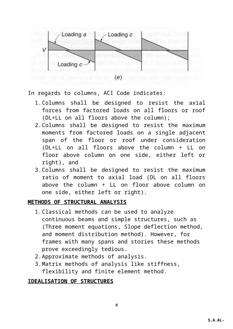
In the Figure below only span CD is loaded by live load. The distortions of the various frame members are seen to be largest in, and immediately adjacent to, the loaded span and to decrease rapidly with increasing distance from the load.
4
S.A.AL-TAAN

(b) LOAD COMBINATIONSThe ACI Code requires that structures be designed for a number of load combinations. For example, factored load combinations might include:
(i) DL+LL;(ii) DL+LL+FL+TL+WL;(iii) Three possible combinations that include, DL, LL, and WL, and(iv) Two combinations that include DL+LL, and EL with some of the
combinations that include SL+RL+HL Once the forces have been calculated for each load combination, the combination of loads that governs for each member can usually be identified by inspection.
SIMPLIFICATIONS IN FRAME ANALYSISSimplifications can be done by means of certain approximations that allow the determination of moments with reasonable accuracy while substantially reducing the amount of computation. Building frames not involving unusual asymmetry of loading or shape, the influence of sidesway caused by vertical loads are determined with sufficient accuracy by dividing the entire frame into simpler subframes. Each of these consists of one continuous beam, plus the top and bottom columns framing into that particular beam. For this partial structure, the far ends of the columns are considered fixed, except for such first-floor or
5
S.A.AL-TAAN

basement columns where soil and foundation conditions dictate the assumption of hinged ends. ACI Code, specifies the following load combinations for floor and roof members:
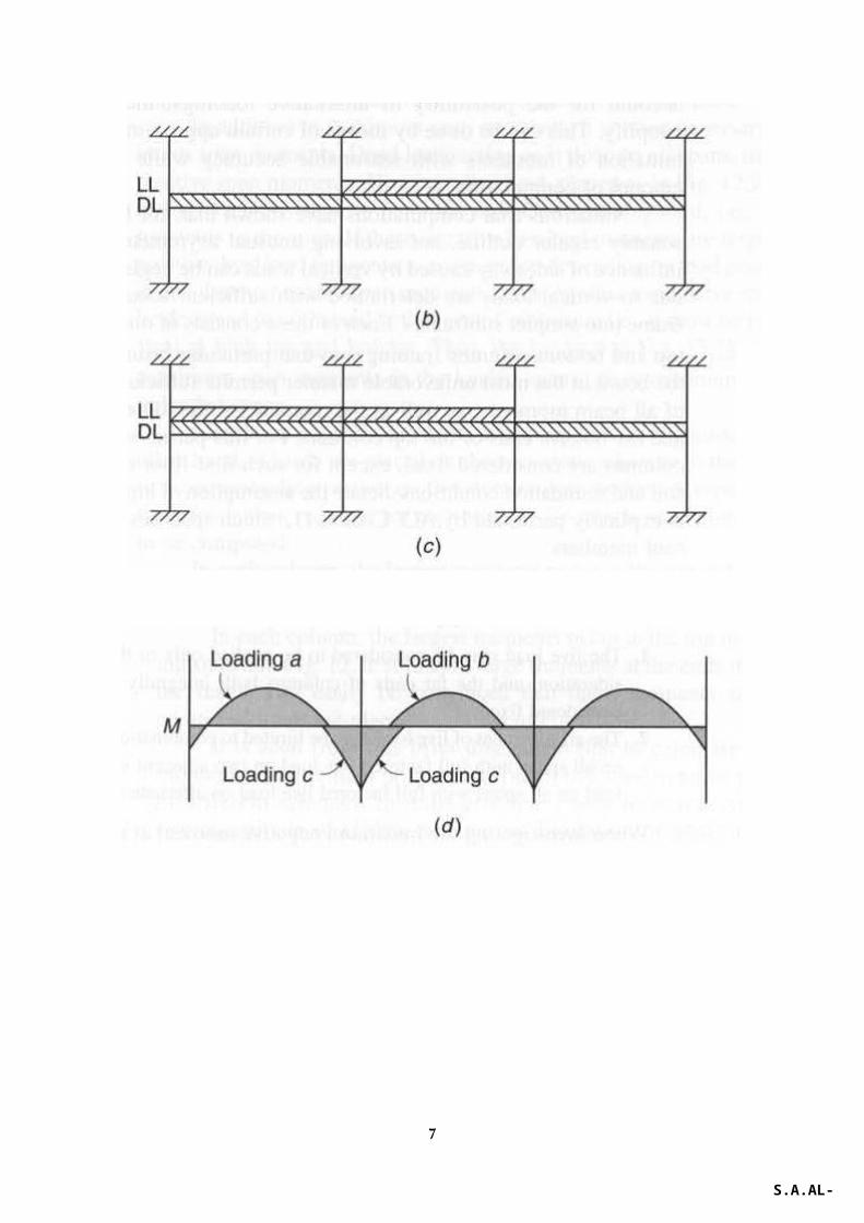
1. The live load may be considered to be applied only to floor or roof under consideration.
2. The arrangement of live load may be limited to combinations of:(a) Factored DL on all spans with full factored live load on two
adjacent spans, and(b) Factored DL on all spans with full factored live load on alternate
spans.
6
S.A.AL-TAAN
In regards to columns, ACI Code indicates:1. Columns shall be designed to resist the axial forces from factored loads
on all floors or roof (DL+LL on all floors above the column);2. Columns shall be designed to resist the maximum moments from factored
loads on a single adjacent span of the floor or roof under consideration (DL+LL on all floors above the column + LL on floor above column on one side, either left or right), and
3. Columns shall be designed to resist the maximum ratio of moment to axial load (DL on all floors above the column + LL on floor above column on one side, either left or right).
METHODS OF STRUCTURAL ANALYSIS1. Classical methods can be used to analyze continuous beams and simple
structures, such as (Three moment equations, Slope deflection method, and moment distribution method). However, for frames with many spans and stories these methods prove exceedingly tedious.
2. Approximate methods of analysis.3. Matrix methods of analysis like stiffness, flexibility and finite element
method.IDEALISATION OF STRUCTURES
7
S.A.AL-TAAN
It is seldom possible for the engineer to analyze an actual complex redundant structure without making certain idealizations.
1. Members are represented by straight lines, generally coincident with the actual centroidal axis.
2. Supports are idealized as rollers, hinges, or rigid joints.3. Loads distributed over a finite area are assumed to be point loads.
In the idealization of R. C. frames, certain questions require special comment. The most important of these pertain to effective span lengths, effective moment of inertia, and conditions of support.
(a)EFFECTIVE SPAN LENGTH A structure is usually represented by simple line diagram, based dimensionally on the centerline distances between columns and beams. The depth of beams and width of columns amount to sizable fraction of their respective spans. The assumption that the members are prismatic with constant moment of inertia, is not correct. A beam intersecting a column may be prismatic up to the column face. From the column face to the column centerline, it has a greatly increased depth , with a moment of inertia that could be considered infinite compared with that of the remainder of the span. A similar variation in width and moment of inertia is obtained for the column.This would increase the support (negative) moment and decrease the span (positive) moment. In addition, the critical section for the negative moment is at the column face and not the column centerline. There are two approaches to deal with this issue. First, decrease the negative moment by (V.a.L/2) and the positive moment by (V.a.L/6).
8

Second, represent the portion of the beam within the column and the portion of the column within the beam as a rigid link (with very large stiffness).
Moment of InertiaThe moment of inertia depends on the extent of cracking, and the cracking itself depends on the moment variation across the span. Regions near the midspan section have moment of inertia of a T-section which is about twice that for rectangular section. At or near the supports where negative moments are dominant, the moment of inertia is that for cracked rectangular section.The ACI Code gives two alternatives for estimating the moment of inertia of beams and columns,
9
S.A.AL-TAANS.A.AL-TAAN
Iv
Iv
Iv Iv
Icol.
Icol.
Icol.
Icol.c/c of columns – column widthhc/2
hb/2
hb/2
S.A.AL-TAAN
hc/2
Iv
Iv Ibeam.
Iv = very large number

i. Use moment of inertia of gross concrete section of the columns and 50% moment of inertia of the gross concrete section of the beams.
ii. Use 70% of the moment of inertia of gross concrete section of the columns and 35% moment of inertia of the gross concrete section of the beams.
© Conditions at SupportsConditions at supports depend on the moment of inertia of the member relative to the moment of inertia of the member upon which it is supported. For example, i. A column supported on relatively small footings, a hinged end may be
assumed. ii. A column supported on continuous footing may be considered fixed.iii. A slab or beam supported on masonry wall, may be considered hinged.
PRELIMINARY DESIGN AND GUIDELINES FOR PROPORTIONING MEMBERSIn making elastic analysis it is necessary to know the dimensions of members.
i. Slabs design are usually controlled by deflections or the negative moments at the supports.
ii. Beams design are controlled by the negative moments and shear at the support where the section is considered rectangular. An approximate depth of (1/16) of the span may be assumed with a width ≈ depth. A value of the reinforcement ratio of ≈ 0.01-0.015 is reasonable.
iii. Columns sizes are controlled by axial loads estimated from the loads on (tributary areas) increased 10% for interior columns and 50% for edge columns due to the moments.
APPROXIMATE ANALYSISi. For vertical loads and continuous members, a point of inflection at
0.211L from the support can be assumed to occur.
10
S.A.AL-TAAN

For frames subjected to wind loads, the portal method may be used to analyze the frame.
11
S.A.AL-TAAN

ACI MOMENTS COEFFICIENTS
i. There are two or more spans.ii. Spans are approximately equal, with the longer of two adjacent spans
not greater than the shorter by more than 20%.iii. Loads are uniformly distributed.iv. The working LL ≤ 3×working DL.v. Members are prismatic.
Shear in end members at first interior support 1.15wu.Ɩn / 2Shear at all other supports wu.Ɩn / 2Wu = total factored uniformly distributed load per unit length of beam or unit area for slabs.
12
S.A.AL-TAAN

Ɩn = clear span for positive moment and shear and the average of two adjacent spans for negative moment.
Beams with more two spans
Beams with two spans only
Slabs with spans not exceeding 3.0 m
Beams in which the sum of the column stiffnesses exceed 8 times the sum of the beam stiffnesses at each end of the span
13
S.A.AL-TAAN

EXAMPLE
For the floor system shown below, design the slab and beams. fc' = 30 MPa and
fy =400 MPa. The slab is loaded with a working LL =12 kPa and a finishing DL = 1.5 kPa. Max. For (ϵt = 0.005, kn = 6.75 MPa, ρmax. =0.02), (ϵt = 0.004, kn = 7.5 MPa, ρmax. =0.0228).
SOLUTION
DESIGN OF SLAB
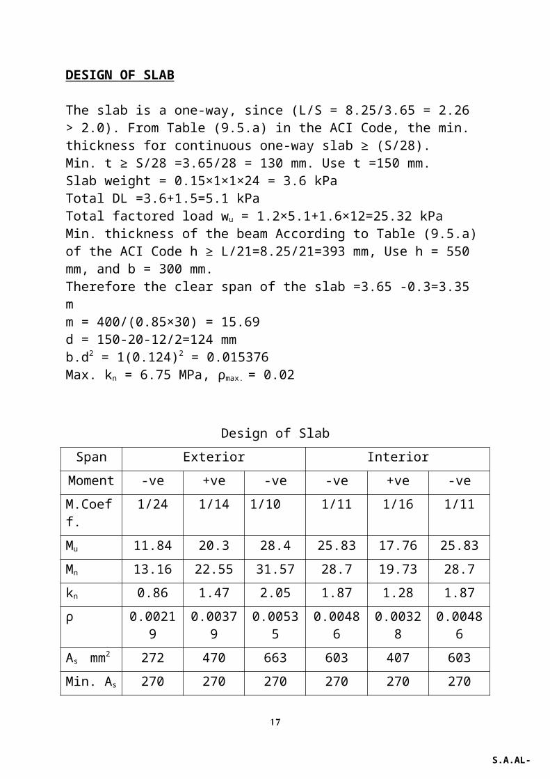
The slab is a one-way, since (L/S = 8.25/3.65 = 2.26 > 2.0). From Table (9.5.a) in the ACI Code, the min. thickness for continuous one-way slab ≥ (S/28).Min. t ≥ S/28 =3.65/28 = 130 mm. Use t =150 mm.Slab weight = 0.15×1×1×24 = 3.6 kPaTotal DL =3.6+1.5=5.1 kPaTotal factored load wu = 1.2×5.1+1.6×12=25.32 kPaMin. thickness of the beam According to Table (9.5.a) of the ACI Code h ≥ L/21=8.25/21=393 mm, Use h = 550 mm, and b = 300 mm. Therefore the clear span of the slab =3.65 -0.3=3.35 m m = 400/(0.85×30) = 15.69d = 150-20-12/2=124 mmb.d2 = 1(0.124)2 = 0.015376Max. kn = 6.75 MPa, ρmax. = 0.02
14
3 @ 3,65 m
4 @ 10.95 m = 43.80 m
3 @
8.25
m =
24
.75
m
S.A.AL-TAAN
=10.95 m

Design of Slab
Span Exterior Interior
Moment -ve +ve -ve -ve +ve -ve
M.Coeff. 1/24 1/14 1/10 1/11 1/16 1/11
Mu 11.84 20.3 28.4 25.83 17.76 25.83
Mn 13.16 22.55 31.57 28.7 19.73 28.7
kn 0.86 1.47 2.05 1.87 1.28 1.87
ρ 0.00219 0.00379 0.00535 0.00486 0.00328 0.00486
As mm2 272 470 663 603 407 603
Min. As 270 270 270 270 270 270Bars size & spacing
10@150 mm c/c
10@150 mm c/c
DESIGN OF THE BEAMSd = 550-60 = 490 mmBeam weight = 0.3×0.4×1×24=2.88 kN/mTotal factored load = 25.32×3.65+1.2×2.88 = 95.87 kN/mMin. As = (1.4/fy)b.d=(1.4/400)300×490 = 515 mm2
Min. As = √fc’/(4fy)= (√30/4/400)300×490 = 503 mm2
Max. kn = 6.75 MPa and ρmax. = 0.002 (for εt = 0.005)Therefore Min. As = 515 mm2
Assume the girder width = 400 mmThe clear span of the beam = 8.25 – 0.4 = 7.85 mWu.Ln
2=95.87(7.85)2 = 5907.75
Design of the positive bending moment region (T-section) .
B ≤ span/4=8.25/4=2.0625 mB ≤ bw + 16 hf =300+16×150 = 2700 mmc/c of beams = 3.65 mtherefore b = 2063 mm.Mu = 421.98 kN.mMn = 468.87 kN.m a = hf =150z = 490 -150/2 = 415 mmAs = 0.468.87/(400×0.415) = 2825 mm2
a = 21 mm
15
S.A.AL-TAAN

z = 490 -21/2 = 479 mmAs = 0.468.87/ (400×0.479) = 2447 mm2 (ρw = 0.0166)Mu = 369.23 kN.mMn = 410.26 kN.m a = 20 mmz = 490 -20/2 = 480 mmAs = 0.41026/(400×0.480) = 2137 mm2
a = 16 mmz = 490 -16/2 = 482 mmAs = 0.41026/(400×0.482) = 2128mm2 (ρw = 0.0145)Design of the double reinforced beams Mn = 656.42 kN.m (Exterior support)Max Mn1= 6.75b.d2 = 6.75×0.3×0.492 = 486.2 kN.mAs1 = 0.02×300×490 = 2940 mm2
Mn2= 656.42 - 486.2 = 170.22 kN.m (-ve M at exterior support)Nc2 = Nt2 = Mn2/(d-d’) = 0.17022/(0.49-0.06) = 0.396 MNAs2 = 0.396/400 = 990 mm2
As = 2940+990 = 3930 mm2
c =0.375d =0.375×490 =184 mm, fs’ = 600(c-d’)/c=600(184-63)/184= 394.6
MPa,As
’= Nc2/(fs’-0.85fc
’) = 0.396/(394.6-0.85×30) = 1073 mm2 Mn = 596.74 kN.m (First Interior support)Mn2= 596.74 - 486.2 = 110.54kN.m (-ve M at interior support)Nc2 = Nt2 = Mn2/(d-d’) = 0.11054/(0.49-0.06) = 0.257 MNAs2 = 0.257/400 = 643 mm2
As = 2940+643 = 3583 mm2
c =0.375d =0.375×490 =184 mm, fs’ = 600(c-d’)/c=600(184-63)/184= 394.6
MPa,As
’= Nc2/(fs’-0.85fc
’) = 0.257/(394.6-0.85×30) = 696 mm2
Design of the Beam
Span Exterior Interior
Moment -ve +ve -ve -ve +ve -ve
M.Coeff. 1/24 1/14 1/10 1/11 1/16 1/11
Mu 246.16 421.98 590.78 537.07 369.23 537.07
Mn 273.51 468.87 656.42 596.74 410.26 596.74kn=Mn/b.d2 3.80 T 9.11 > 6.75 8.28 > 6.75 T 8.28 > 6.75
ρ 0.01034 0.0166 0.0145
As mm2 1520 2447 3913 3583 2128 3583
16
S.A.AL-TAAN
Min. As 515 515 515 515 515 515
As’ mm2 ----- ---- 1073 696 ---- 696
As bars 4 # 22 7 # 22 8 # 25 8 # 25 6 # 22 8 # 25
As' bars 3#22 2#22 2#22
Design of the Girders .
Girder width = 400 mm (assumed before).Assume girder depth = 650 mm.Self-weight of the girder = 0.4×0.5×1×24 = 4.8 kN/m.Factored dead load on the girder = 1.2×4.8 = 5.76 kN/m.Total factored load on the beam = 95.87 kN/mTotal factored live load on the beam = 1.6×12×3.65 = 70.08 kN/mFactored live load on the girder (from the beams) = 1.6×12×3.65×8.25/2=289.02 kN (concentrated load on the exterior girder)Factored live load on the girder (from the beams) = 2×289.02 = 578.04kN (concentrated load on the interior girder)Factored dead load on the beams = 95.87 – 70.08 = 25.79 kN/m Factored dead load on the girder (from the beams) = 25.79×8.25/2 = 106.38 kN (concentrated load on the exterior girder)Factored dead load on the girder (from the beams) = 2×106.38 = 212.76kN (concentrated load on the interior girder)
Loads on Exterior girders
Loads on Interior girders
17
wud = 5.76 kN/m
Pud = 106.38kN, Pul =289.02 kNPud = 106.38kN, Pul =289.02 kN
wud = 5.76 kN/m
Pud =212.76kN, Pul =578.04 kNPud = 212.76kN, Pul =578.04 kN